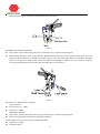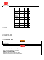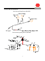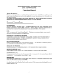
1
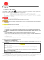
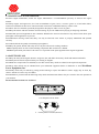
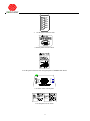
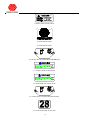
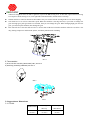
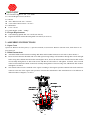
Operator’s Manual R WY28T Lawn Mower ● Safety Information ● Adjustments & Repairs ● Accessory Worldlawn Power Equipment, Inc. Industrial Park 2415 Ashland Ave. Beatrice, NE 68310 Toll Free Number: 1-800-267-4255 OPERATOR’S MANUAL This manual contains assembly, operating, maintenance, adjustment, and safety instructions for your WY28T lawnmower. Before operating your mower, read this manual in its entirety carefully. By following the operating, maintenance, adjustment, and safety instructions, you will prolong the life of your mower, maintain its maximum efficiency, and promote safe operation. Keep this mower Owner’s Manual when lent or transferred. If this mower Operator’s Manual becomes lost, damaged, or illegible, replace it immediately; replacements may be downloaded from our website (www.worldlawnpowerequipment.com) or ordered from our sales department. If additional information is needed, contact our sales department or a dealer. Always be ready to provide the model number and serial number. POTENTIAL HAZARD · This product is a piece of power equipment. WHAT CAN HAPPEN · Failure to follow safe operating practices can result in serious operator injury or even death. HOW TO AVOID THE HAZARD · Keep all shields, guards, and safety devices (especially the grass discharge system) in place and in proper working condition. · Stop machine and wait for all moving parts to stop, remove spark plug wires or remove key before adjusting, servicing, or performing maintenance. · If mower deck becomes clogged, stop machine and wait for all moving parts to stop. Remove spark plug wire or remove key before cleaning blockage. · Keep hands, feet, and clothing away from power driven parts. · Keep others off mower. POTENTIAL HAZARD · Gasoline is harmful or fatal if swallowed. Long-term exposure of vapor causes cancer in laboratory animals. WHAT CAN HAPPEN · Failure to use caution may cause serious injury or illness. HOW TO AVOID THE HAZARD · Avoid prolonged breathing of vapor. · Keep face away from nozzle and gas tank opening. · Keep away from eyes and skin. · Never siphon by mouth. TABLE OF CONTENTS 1. SAFETY…………………………………………………………………………………... 5 1.1 Safety Alert Symbol ……………………………………………………………………….. 5 1.2 Training ………………………………………………………………………………….. 5 1.3 Preparation ……………………………………………………………………………….. 5 1.4 Operation ……………………………………………………………………………….... 7 1.5 Maintenance & Storage …………………………………………………………………..... 10 1.6 Safety Decals …………………………………………………………………………. . . . 10 2. SPECIFICATIONS……………..………………………………………………………….. 13 2.1 Model Number ……………………………………………………………………………. 13 2.2 Engine ………………………………………………………………………………….... 13 2.3 Frame Assembly…………………………………………………………………………… 13 2.4 Drive System ……………………………………………………………………………... 13 2.5 Cutting Deck……………………………………………………………………………… 13 2.6 Operator Controls…………………………………………………………………………. 13 2.7 Accessories ……………………………………………………………………………..... 14 2.8 Approximate Dimensions ………………………………………………………………….. 14 2.9 Torque Requirements ……………………………………………………………………… 15 3. ASSEMBLY INSTRUCTIONS …………………………………………………………….. 15 3.1 Open Crate ……………………………………………………………………………….. 15 3.2 Initial Instructions ………………………………………………………………………… 15 3.3 Service Engine ……………………………………………………………………………. 15 4. OPERATION INSTRUCTIONS…………………………………………………………………….. 16 4.1 Pre-start ………………………………………………………………………………….. 16 4.2 Starting Engine ………………………………………………………………………….... 17 4.3 Mowing ………………………………………………………………………………….. 17 4.4 Moving Operation ………………………………………………………………………… 17 4.5 Stopping Engine …………………………………………………………………………... 17 5. MAINTENANCE & ADJUSTMENTS……………………………………………………………... 18 5.1 Periodic Maintenance ……………………………………………………………………… 18 5.1.1 Check the Engine Oil Level ……………………………………………………………… 18 5.1.2 Clean Engine Air Cooling System…………………………………………………………. 18 5.1.3 Clean Grass Build-up from Under Deck…………………………………………………… 5.1.4 Check Mower Blades…………………………………………………………………….. 19 19 5.1.5 Check Safety Interlock System …………………………………………………………… 20 3 5.1.6 Check for Loose Hardware ……………………………………………………………… 20 5.1.7 Service Air Cleaner………………………………………………………………………. 20 5.1.8 Change Engine Oil……………………………………………………………………….. 20 5.1.9 Check Tire Pressure……………………………………………………………………… 21 5.1.10 Check Condition of Belts ……………………………………………………………….. 21 5.1.11 Lubricate Grease Fittings ……………………………………………………………….. 21 5.2 Adjustments ………………………………………………………………………………. 22 6. TROUBLESHOOTING……………………………………………………………………. 26 7. SERVICE BATTERY ……………………………………………………………………... 27 7.1 Check Battery…………………………………………………………………………... 28 7.2 Connecting the Negative Battery Cables………………………………………………….. 28 7.3 Maintenance Period …………………………………………………………………….. 29 8. ELECTRICAL DIAGRAM …………………………………………………………………………. 30 9. LIMITED WARRANTY……………………………………………………………………………... 31 4 1. SAFETY 1.1 SAFETY ALERT SYMBOL This SAFETY ALERT SYMBOL is used both in this manual and on the machine to identify important safety messages which must be followed to avoid accidents. This symbol means: ATTENTION! BECOME ALERT! YOUR SAFETY IS INVOLVED! The safety alert symbol above alerts you to unsafe actions or situations by the word DANGER, WARNING, or CAUTION. White letters on red background. Failure to observe the safety instructions could result in death or serious injury. Black letters on orange background. Failure to observe the safety instructions could result in death or serious injury. Black letters on yellow background. Failure to observe the safety instructions may result in slight or serious injury. 1.2 TRAINING 1.2.1 Regard the mower as a piece of power equipment. The operator needs to be trained before operating this unit. 1.2.2 Read the instructions carefully. Be thoroughly familiar with controls and the proper use of the equipment. 1.2.3 Never allow children, teenagers, or adults to operate the equipment without proper instruction. 1.2.4 Keep everyone, especially children and pets, away from the area of operation. Remember that the operator or user is responsible for accidents or hazards occurring to other people or their property. 1.3 PREPARATION 1.3.1 Evaluate the terrain to determine what accessories and attachments are needed to properly and safely perform the job. Only use accessories and attachments approved by Worldlawn Power Equipment, Inc. 1.3.2 The use of personal protective equipment, such as (but not limited to) protection for the eyes, ears, feet, and head is recommended. POTENTIAL HAZARD · This machine produces sound levels in excess of 85dBA at the operator’s ear when in operation. WHAT CAN HAPPEN · Exposure to sound levels of 85dBA or above for extended periods of time can cause hearing loss. HOW TO AVOID THE HAZARD · Wear hearing protection when operating this machine. 1.3.3 While mowing, always wear ample footwear and long trousers. Do not operate equipment when barefoot or when wearing open sandals. 1.3.4 Thoroughly inspect the area where the equipment is to be used and remove all stones, sticks, wires, bones, and other foreign objects which may damage the equipment or cause personal injury to operator or bystanders. 5 POTENTIAL HAZARD · Engine exhaust contains carbon monoxide, which is an odorless deadly poison. WHAT CAN HAPPEN · Carbon monoxide can kill you. HOW TO AVOID THE HAZARD · Do not run engine indoors or in a small confined area where dangerous carbon monoxide fumes can collect. POTENTIAL HAZARD · In certain conditions gasoline is extremely flammable and highly explosive. WHAT CAN HAPPEN · A fire or explosion from gasoline can burn you, others, and cause property damage. HOW TO AVOID THE HAZARD · Do not smoke while refueling, and stay away from an open flame or where gasoline fumes may be ignited by a spark. · Refuel only outdoors. · Store gasoline in an approved container and keep it out of the reach of children. · Add fuel before starting the engine. Never remove the cap of the fuel tank or add fuel when engine is running or when the engine is hot. · Never fill the fuel tank so that gasoline level rises above a level that is 3/8"(10mm) below the bottom of the filler neck to allow for gasoline expansion and prevent fuel spillage. · If fuel is spilled, DO NOT attempt to start the engine. Move away from the area of the spill and avoid creating any source of ignition of the fuel until vapors have dissipated. · Do not operate without entire exhaust system in place and in proper working condition. 6 POTENTIAL HAZARD · In certain conditions gasoline is extremely flammable and highly explosive. WHAT CAN HAPPEN · A static charge can ignite gasoline vapors. A fire or explosion from gasoline can burn you, others, and cause property damage. HOW TO AVOID THE HAZARD · Purchase and store gasoline only in an approved container. · Always place gasoline containers on the ground away from your vehicle while filling. · Do not fill gasoline containers inside a vehicle or on a truck or trailer bed, because interior carpets or plastic truck bed liners may insulate the container and slow the loss of any static charge. · When practical, remove gas-powered equipment from the truck or trailer and refuel the equipment with its wheels on the ground. · If this is not possible, then refuel such equipment on a truck or trailer from a portable container, rather than from a gasoline dispenser nozzle. · If a gasoline dispenser nozzle must be used, keep the nozzle in contact with rim of the fuel tank or container opening at all times until fueling is complete. POTENTIAL HAZARD · Gasoline vapor can collect inside enclosed trailers and may be ignited by electrical sparks or hot engine/exhaust components. WHAT CAN HAPPEN · Explosion and fire may occur, resulting in property damage, personal injury, and/or death. HOW TO AVOID THE HAZARD · Provide adequate ventilation of any enclosed trailer to prevent build up of gasoline vapors, especially at floor level. · Refuel only outdoors, never inside an enclosed trailer. · Be sure all fuel tanks and gasoline storage containers have proper caps installed to prevent spillage and minimize vapor escaping into the trailer. · Do not place any equipment that is leaking gasoline into an enclosed trailer. 1.4 OPERATION Although hazard control and accident prevention partially are dependent upon the design and configuration of the equipment, these factors are also dependent upon the awareness, concern, prudence, and proper training of the personnel involved in the operation, transport, maintenance, and the storage of the equipment. It is essential that all Operator Safety Mechanisms be connected and in operating condition prior to use for mowing. 7 POTENTAL HAZARD · Operating engine parts, especially the muffler, become extremely hot. WHAT CAN HAPPEN · Severe burns can occur on contact. · Debris, such as leaves, grass, brush, etc. can catch fire. HOW TO AVOID THE HAZARD · Allow engine parts, especially the muffler, to cool before touching. · Remove accumulated debris from muffler and engine area. · Install and maintain a spark arrester in working order before using equipment on forest-covered, grass-covered, or brush-covered unimproved land. POTENTIAL HAZARD · Hands, feet, hair, clothing, or accessories can become entangled in rotating parts. WHAT CAN HAPPEN · Contact with rotating parts can cause traumatic amputation or severe lacerations. HOW TO AVOID THE HAZARD · Do not operate the machine without guards, shields, and safety devices in place and working properly. · Keep hands, feet, hair, jewelry, or clothing away from rotating parts. 1.4.1 Give complete, undivided attention to the job at hand. 1.4.2 Mow only in daylight or good artificial light; keep away from holes and hidden hazards. NEVER carry passengers. DO NOT operate the mower when children or others are in the area! 1.4.3 When feasible, avoid operating the equipment in wet grass. 1.4.4 Use extreme caution when mowing and/or turning on slopes as loss of traction and/or tip-over could occur. The operator is responsible for safe operation on slopes. POTENTIAL HAZARD · Mowing on wet grass or steep slopes can cause sliding and loss of control. WHAT CAN HAPPEN · Wheels dropping over edges, ditches, steep banks, or water can cause rollovers, which may result in serious injury, death, or drowning. HOW TO AVOID THE HAZARD · Do not mow on slopes when grass is wet. · Do not mow near drop-offs or near water. · Do not mow on slopes greater than 15 degrees. · Reduce speed and use extreme caution on slopes. · Avoid sudden turns or rapid speed changes. 8 Use a hand trimmer only near drop-offs, ditches, steep banks, or water. This area can be dangerous, see Figure 1. Progressively greater care is needed as the slope increases. Always avoid sudden starting or stopping on a slope. If tires lose traction, disengage the blades and proceed slowly off the slope. Avoid sudden starts when mowing uphill. Mower may tip backwards. Be aware that loss of traction may occur going downhill. Weight transfer to the front wheels may cause drive wheels to slip and cause loss of braking and steering. Watch for ditches, holes, rocks, dips, and rises that change the operating angle, as rough terrain could overturn the machine. Use extreme care with grass catchers or attachments. These can change the stability of the machine and cause loss of control. 1.4.5 Stop the blades when transporting the mower to and from the area to be mowed. 1.4.6 Never operate the mower with defective guards, shields, or covers. Always have safety shields, guards, switches, and other devices in place and in proper working condition. 1.4.7 DO NOT change the engine governor setting or overspend the engine. Operating an engine at excessive speed may increase the hazard of personal injury. 1.4.8 Disengage PTO before starting engine. 1.4.9 Start the engine carefully with feet well away from the blades. 1.4.10 Keep hands, feet, and clothing away from rotating parts while the mower is being operated. 1.4.11 Stop engine, wait for all mowing parts to stop, and remove key: Before checking, cleaning, or working on the mower. After striking a foreign object (inspect mower for damage and make repairs before restarting and operating the mower). Before clearing blockages. Whenever you leave the mower. Stop the engine and wait for all moving parts to stop: Before refueling. Before dumping the grass catcher. 1.4.12 The fuel system is provided with a shut-off valve. CLOSE VALVE: When the machine will not be used for a few days. During transport to and from the job. When parked inside a building. 1.4.13 This mower was designed for one operator only. Keep all others away from mower during operation. 1.4.14 DO NOT mow with the discharge deflector raised, removed, or altered unless there is a grass collection system or mulch kit in place and working properly. 1.4.15 Be aware of the mower discharge and direct discharge away from others. 1.4.16 DO NOT operate the mower under the influence of alcohol and/or drugs. 1.4.17 Use extra care when approaching blind corners, shrubs, trees, or other objects that may obscure vision. 9 1.5 MAINTENANCE AND STORAGE 1.5.1 For engine maintenance, follow the engine manufacturer’s recommendations precisely as stated in the engine manual. 1.5.2 Keep engine and engine-area, free from accumulation of grass, leaves, excessive grease or oil and other debris, which can accumulate in these areas. These materials can become combustible and may result in a fire. 1.5.3 Store fuel in a container specifically designed for this purpose and in a cool, dry place. 1.5.4 Keep the mower and fuel container in locked storage to prevent children from playing or tampering with them. 1.5.5 Gasoline powered equipment or fuel containers should not be stored in a basement or any enclosed area where open pilot lights or heat appliances are present. 1.5.6 Maximum mowing results and safety can only be achieved if the mower is properly maintained and operated correctly. 1.5.7 Check all bolts frequently to maintain proper tightness. 1.5.8 Keep all guards, shields, and safety devices in place and in safe working condition. 1.5.9 Frequently check for worn or deteriorating components that could create a hazard. 1.5.10 All replacement parts must be the same as or equivalent to the parts supplied on the original equipment. 1.6 SAFETY DECALS 1.6.1 Keep all safety decals legible. Remove all grease, dirt, and debris from safety decals and instructional labels. 1.6.2 Safety decals must be replaced if they are missing or illegible. 1.6.3 When new components are installed, be sure that current safety decals are affixed to the replaced components. 1.6.4 New safety decals may be obtained from your authorized equipment dealer or distributor or from Worldlawn Power Equipment, Inc. 1.6.5 Safety decals may be affixed by peeling off the backing to expose the adhesive surface. Apply only to clean, dry surface. Smooth to remove any air bubbles. 1.6.6 Familiarize yourself with the following safety decals and instruction labels. They are critical to the safe operation of your machine. Decals and their locations are as follows: 1. On the panel of rear frame 2. On the panel of console (Electric) 10 3. On the panel of mower deck 4. On the panel of mower deck 5. On the panel of mower deck and guard plate of LH&RH belt shield 6. In front of the console plate 7. On the panel of rear frame 11 8. On the panel of mower deck 9. On the Mower Deck 9. On the Mower Deck 10. On the panel of console (Recoil BS&Honda) 11. On the left side of front frame 12. On the right side of front frame 13. On the panel of console (Recoil Kawasaki) 14. On the front of the mower deck 12 2. SPECIFICATIONS 2.1 Model Number: WY28T11BS、WY28T11BSE、WY28T11HD、WY28T11HDE 2.2 Engine: MODEL ENGINE STARTER WY28T11BS B&S10.5HP Intek I\C Recoil WY28T11BSE B&S11.5HP Intek I\C Electric WY28T11HD HONDA 11HP Recoil WY28T11HDE HONDA 11HP Electric 2.3 Frame Assembly Front Frame: Rectangle tube 1.6"×1.18"×0.12" Thickness (Steel plate of engine frame): 0.12" Fuel Tank: 2 gallon (7.6 liter) seamless polyethylene Drive Wheel: 13×4" two-ply pneumatic tubeless. Caster Wheel: 8×3", smooth, needle bearing pneumatic tubeless. 2.4 Drive System Type: Belt drive with twin power belts for increased friction to pulley surface. Transmissions: Peerless 3-speed transmission Steering/Travel Control: Clutch/brake fingertip steering, key lock switch. Brakes: band brake, one on each wheel. Safety Group: Hand actuated operator presence system with blade clutch and transmission interlock to engine kills. Forward Speed Range: 0-4.38mph(0-7km/h) 2.5 Cutting Deck Type: Floating deck True Cutting Width: 28"(71.1cm) Blade engagement: Manual control Cutting Height Adjustment: Manual adjustment 1.5″ (3.8cm) to 4.0″ (10.16cm) in 0.5″ (1.27cm) increments. Cutting Blades: 0.2"(5mm) thick, two 14.5″(36.8cm) blades. Cutting Deck Belts: A-section. Synchronous Belt: 1200-8M 2.6 Operator Controls (See FIG 1) Key switch: Located on the control panel (some recoil starter models are not equipped with key switch). Recoil starter has two positions. Turning to "on" starts the engine; turning to "off" stops the engine. Electronic ignition model has three positions. When starting, turn to "start" position; then remove your hand. Throttle Control: Located on the control panel. Throttle is used to control engine speed. Moving throttle lever forward will increase engine speed and moving throttle lever to the rear will decrease engine speed. Some recoil starter models are not equipped with key switch. Move the throttle lever to the rearmost position, then the engine will be switched off. Blade Drive Lever: Push the mower blade drive lever forward to the engage position. Pull the mower blade drive lever backward to the disengage position to stop the blades. Hand actuated operator presence lever: When in normal operation, compress the operator presence lever. When released, engine will kill. Steering Brake Levers: While squeezing the steering lever handles with both hands, release right and left neutral latches; then release right and left steering levers to move forward. When the steering levers are released, the mower 13 will travel straight forward. To make a right turn, squeeze the RH steering lever. To turn left, squeeze the LH steering lever. Squeeze both steering levers, lock right and left neutral latches, and the mower will stop. Neutral Latches: Located on bottom of the handles. They are used to lock the steering brake levers when stopping. Gear shift lever: It is used to control the speed. When the machine is moving forward, if you’d like to change low gear into high gear, push gear shift lever forward, then you can change the gear. When changing high gear into low gear, you must stop the machine, then change the gear. Fuel shut-off valve: The fuel shut-off valve is used to shut off the fuel when the machine will not be used for a few days, during transport to and from the jobsite, and when parked inside a building. FIG 1 2.7 Accessories: a) Grass catcher assembly (WY32-NGC): 80L, see FIG 2 b) Mulching Assembly (2832010): See FIG 3 FIG 2 FIG 3 2.8 Approximate Dimensions: 2.8.1 Width: Without Deck Discharge chute up Discharge chute down 27.8in (70.5cm) 28.8in (73.2cm) 37.8 in (96 cm) 14 2.8.2 Overall Length: 67.3in(171.0cm) 2.8.3 Overall Height: 42.9in (109.0cm) 2.8.4 Tread: Drive Wheel Tread: 23in(58.6cm) Caster Wheel Tread: 20.6in(52.3cm) 2.8.5 Wheelbase: 31.9in(81cm) 2.8.6 Curb Weight: 338lbs(154Kg) 2.9 Torque Requirements Cutter Housing Spindle Nut: 66± 13ft-lb (90±18N-m) Engine Deck/Front Frame Mounting Bolts: 40-52ft-lb (55-70 N-m) 3. ASSEMBLY INSTRUCTIONS 3.1 Open Crate Open crate. Remove the loose parts (i.e., operator’s manual, etc) from crate. Remove unit from crate; check there are no loose parts left. 3.2 Initial Instructions Attach the handle with four M10×25 Flange Hd. Bolts and four M10 locknuts on each side as shown in FIG 4. Insert rod end connector threaded stud of left and right steering linkage rod assemblies through hole of left and right brake swing arms; add M6 nut and washer 8 and tighten. Next, insert rod end connector threaded stud of shift control rod assembly through hole of shift control arm; add M6 nut and washer 6 and tighten. To finish, insert rod end connector threaded stud of blade control rod assembly through hole of tension swing arm; add M6 nut and washer 6 and tighten. See FIG 4 The Throttle Cable must be attached to the engine according to the Engine Operator's Manual. The Fuel Tank Line connects to the line of the engine. (The positions of Fuel Filter and Throttle Cable Attachment are a bit different on different models of Engines.) See FIG 5 15 FIG 4 FIG 5 3.3 Service Engine Engine is shipped without oil. Fill to the appropriate level with SAE10W-30 or 10W-40. 4. OPERATION INSTRUCTIONS Read these instructions carefully before operating the mower. 4.1 PRE-START Fill fuel tanks. For best results use only clean, fresh, regular grade, unleaded gasoline with an octane rating of 87 or higher. Regular grade leaded gasoline may also be used; however, combustion chamber and cylinder head will require more frequent service. See Engine Owner’s Manual. Do not add oil to gasoline. Do not overfill fuel tank. Open the fuel tank shut-off valve. Make sure you understand the controls, their locations, their functions, their safety requirements, and how to stop quickly. POTENTIAL HAZARD · The rotating blades under the mower deck are dangerous. WHAT CAN HAPPEN · Blade contact can cause serious injury or kill you. HOW TO AVOID THE HAZARD · DO NOT put hands or feet under the mower or mower deck when the blades are engaged. Refer to Maintenance, Section 5, and perform all necessary inspection and maintenance steps. Check tire pressure in drive wheels. Proper inflation pressure for tires is 30psi (210kpa). Check tire pressure in caster wheels. Proper inflation pressure for tires is 30psi (210kpa). 16 4.2 Starting Engine Turn the key switch to the “ON” position. The transmission must be in neutral, the blade drive lever must be disengaged. 1)For recoil with key, turn the key switch to the “ON” position, pull the cable to start the engine. 2)For recoil without key, intermittently pull the cable to start the engine. 3)For electric start, turn the key switch to the “Start” position to start the engine. On a cold engine, place the throttle midway between the “SLOW″ and “FAST″ positions and push choke lever forward to the “ON″ position. Turn ignition switch to the “start″ position. Release the switch as soon as the engine starts. 4.3 MOWER OPERATION Push blade drive lever forward to engage blades. Pull blade drive lever back to disengage blades. Be sure that all persons are clear of mower deck and discharge area before engaging PTO. IMPORTANT: Set the throttle to “midway″ position. Push blade drive lever to the “ROTATE″ position. Speed up the throttle, begin to mow. Stopping the blades: Set the throttle to the “midway″ position, pull the mower blade drive lever backward to the “disengage” position to stop the blades. POTENTIAL HAZARD · An uncovered discharge opening will allow objects to be thrown in an operator’s or bystander’s direction. Also, contact with the blade could occur. WHAT CAN HAPPEN ·Thrown objects or blade contact can cause serious injury or death. HOW TO AVOID THE HAZARD ·Never operate the mower with the discharge deflector raised, removed, or altered unless there is a grass collection system or mulch kit in place and working properly. 4.4 Moving Operation Squeeze the right and left steering lever handle bars and move neutral latches into the lock position. Release handle bars and select speed by moving the gear shift lever from the neutral position to the desired speed. Squeeze the right and left steering levers, release the locks, and then release the steering levers to move forward slowly. Squeeze the right steering lever to turn right and the left steering lever to turn left. 4.5 Stopping engine: Pull the blade drive lever backward to the disengage position to stop the blades. Squeeze the right and left steering lever handle bars and move neutral latches into the lock position. Rotate key switch to the “OFF″ position. Remove the key to prevent children or other unauthorized persons from starting the engine. Close fuel shut-off valve when the machine will not be used for a few days, transporting, and when the unit is parked inside a building. 17 5.MAINTENANCE&ADJUSTMENTS POTENTIAL HAZARD · While maintenance or adjustments are being made, someone could start the engine. WHAT CAN HAPPEN · Accidental starting of the engine could seriously injure you or other bystanders. HOW TO AVOID THE HAZARD · Remove the key from the ignition switch and pull the wire off the spark plug before you do any maintenance. Also push the wire aside so it does not accidentally contact the spark plug. POTENTIAL HAZARD · The engine can become very hot. WHAT CAN HAPPEN · Touching a hot engine can cause severe burns. HOW TO AVOID THE HAZARD · Allow the engine to cool completely before servicing or making repairs around the engine area. 5.1 PERIODIC MAINTENANCE 5.1.1 Check the engine oil level. Service Interval: Daily Make sure unit is on a level surface. Stop engine, wait for all moving parts to stop, remove key or pull out spark plug lead. Check when engine is cold. Clean area around dipstick. Remove dipstick and wipe oil off. Reinsert the dipstick. Do not screw into place. Remove the dipstick and read the oil level. If the oil level is low, add oil to bring the oil level up to the "FULL" mark on the dipstick. Use oil as specified in the Engine Owner’s Manual. IMPORTANT: DO NOT operate the engine with the oil level below the "LOW" or "ADD" mark on the dipstick or over the "FULL" mark. 5.1.2 Clean Engine Air Cooling System. Service Interval: Daily or more often in dry conditions Stop engine, wait for all moving parts to stop, and remove the key. Clean all debris from rotating engine air intake screen and from around engine shrouding. 18 POTENTIAL HAZARD · Excessive debris can cause the engine and hydraulic system to overheat. WHAT CAN HAPPEN · Excessive debris around the engine cooling air intake and inside of the pump compartment can create a fire hazard. HOW TO AVOID THE HAZARD · Clean all debris from around the engine and hydraulic pumps daily. a) Stop engine, wait for all moving parts to stop, and remove the key. b) Clean all debris from rotating engine air intake screen and from around engine shrouding. 5.1.3 Clean grass build-up from under deck. Service Interval: Daily Stop engine, wait for all moving parts to stop, and remove key. Clean out any grass build-up from the underside of deck and in discharge chute. 5.1.4 Check mower blades. Service Interval: Daily Stop engine, wait for all moving parts to stop, and remove key or pull out spark plug lead. Lift deck. Inspect blades and sharpen or replace as required. Re-install the blades (if they were removed) by placing a block of wood between the front or rear baffles and the blade; then torque the blade bolts to 66±13ft-lb (90±18N-M). Be sure the spring disk washer cone is installed toward the bolt head.(See FIG 6) FIG 6 19 POTENTIAL HAZARD ·Operating a mower deck with loose or weakened blade bolts can be dangerous. WHAT CAN HAPPEN · A loose or weakened blade bolt could allow a blade rotating at a high speed to come out from under the deck, causing serious injury or property damage. HOW TO AVOID THE HAZARD ·DO NOT lubricate the threads of the bolt or spindle before assembly. ·Torque the blade bolt to 66±13ft-lb (90±18N-M). ·Stop engine, wait for all moving parts to stop, and remove key or pull out spark plug lead before removing blades. 5.1.5 Check safety interlock system. Service Interval: Daily Check starting circuit: - Ignition switch must be in the “ON” or “START” position. - Transmission must be in neutral. - Blade drive lever must be disengaged to start engine with recoil starter. Check engine "kill" (flameout) circuit: Remove your hands from the Operator Presence Control Lever when the engine is running and the engine should stop running within 3 seconds. NOTE: If machine does not pass any of these tests, do not operate. Contact your authorized WORLDLAWN POWER EQUIPMENT SERVICE DEALER. It is essential that operator safety mechanisms be connected and in proper operating condition prior to use for mowing. 5.1.6 Check for loose hardware. Service Interval: Daily Stop engine, wait for all moving parts to stop, and remove key. Visually inspect machine for any loose hardware or any other possible problem. Tighten hardware or correct the problem before operating. 5.1.7 Service air cleaner. Service Interval: 50 hrs Check more often under severe conditions. See engine manual for additional information. Stop engine, wait for all moving parts to stop, and remove the key. Loosen retaining clips and remove air cleaner compartment cover. Remove paper element. Check the condition of the paper element. Replace if dirty, bent or damaged. Do NOT wash or use pressurized air to clean paper element or inner element. 5.1.8 Change engine oil. Service Interval: 100 hrs NOTE: Change oil and filter after first five (5) hrs. of operation. Stop engine, wait for all moving parts to stop, and remove key. 20 Drain oil while engine is warm from operation. Replace the oil filter every other oil change. Clean around oil filter and unscrew filter to remove. Before reinstalling new filter, apply a thin coating of oil on the surface of the rubber seal. Turn filter clockwise until rubber seal contacts the filter adapter; then tighten filter an additional 2/3 to 3/4 turn. Clean around oil fill cap and remove cap. Fill to specified capacity and replace cap. Use oil recommended in engine owner’s manual. DO NOT overfill. Start the engine and check for leaks. Stop engine and recheck oil level. 5.1.9 Check tire pressure: Service Interval: 40hrs Stop engine, wait for all moving parts to stop, and remove key. Check tire pressure in drive tires. Inflate drive tires to 30psi (210kPa). Check tire pressure in caster tires. Inflate caster tires to 30PSI(210kPa). 5.1.10 Check condition of belts: Service Interval: 40hrs Stop engine, wait for all moving parts to stop, and remove key. Check all the belts. Remove the left and right belt shields of deck and lay them aside to inspect belts. See Sections 5.2.2, 5.2.2.1, and 5.2.3 for belt adjustment. 5.1.11 Lubricate grease fittings: Service Interval: Refer to chart Stop engine, wait for all moving parts to stop, and remove key. See the FIG 7. LUBRICATION CHART FITTING LOCATIONS FITTING TIMES SERVICE INTERVAL 1 1 50hrs 2 1 50hrs FIG 7 21 5.2 ADJUSTMENTS IMPORTANT: Disengage PTO, shut off engine, wait for all moving parts to stop, and remove key before servicing, cleaning, or making adjustments to the unit. 5.2.1 Cutting Height Adjustment. Stop engine, wait for all moving parts to stop, and remove key or pull out spark plug lead. Disengage Blade. NOTE: When changing cutting height positions, always come to a complete stop and disengage the blade. Insert height adjustment pin into the hole corresponding to desired cutting height. See decal on deck lift plate. Move lever out of transport position and down onto height adjustment pin to mow at selected height. See FIG 8. FIG 8 5.2.2 Blade Drive Belt Adjustment and Replacement. Stop engine, wait for all moving parts to stop, and remove key or pull out spark plug lead. Remove the belt cover. Adjust the mower deck belt using a belt tension gauge. Engage the blade drive lever, tension the mower belt, and adjust the belt so that the belt moves 1/4″ with 10 pounds of pressure. Adjust the tension by tightening or loosening the nut M10. (See FIG 9). Engage the blade drive lever,loosen the nut, tension the slot forward. Make sure the belt tightening is suitable. (Give the belt tension side the force of 1-2KG, the belt deflection is 7-9mm/10 lbs pull with ½” deflection.) (See FIG 9) 5.2.2.1 Synchronous Belt Adjustment & Replacement Stop engine, wait for all moving parts to stop, and remove key or pull out spark plug lead. Remove blade transmission belt according to reference method 5.2.2, then loosen nut in the idler pulley, take the synchronous belt from the axis pin, then install the new synchronous belt in reverse order. (See FIG9) 5.2.2.2 Blade Brake Pad Replacement Stop engine, wait for all moving parts to stop, and remove key or pull out spark plug lead. Remove the belt cover, turn the shift arm, move shift arm away from pulley, remove bolts and nuts, replace with new brake pad, install bolts and nuts, and make blade brake pad aim at the belt pulley groove center, then screw down the nut. Test blade brake system; blade brake pad can make rapid rotary blades stop running in 3 seconds. (See FIG 9) 22 FIG 9 5.2.3 Transmission Drive Belt Adjustment. Stop engine, wait for all moving parts to stop, and remove key or pull out spark plug lead. Transmission drive belt is on the underside of the engine frame weldment. Adjust the belt so that the belt moves 1/4″ with 10 pounds of pressure; adjust the tension by moving transmission drive idler pulley, then tighten all the nuts.(See FIG 10) Loosen the nut on the tension pulley of the transmission drive belt. Remove the tension pulley and the belt you need to replace. Install the new belt, then install the transmission drive pulley in reverse order. Adjust the belt according to the method of belt adjustment, then tighten the nut. (See FIG 11) FIG 10 5.2.4 Drive Control Adjustments Stop engine, wait for all moving parts to stop, and remove key or pull out spark plug lead. The drive control is a system of interconnected machine elements made up of steering and braking functions, that is to say, one steering lever applies to neutral latch lock position or neutral latch unlock position. When two steering levers are in neutral lock position, the power is disengaged. To brake, adjust brake lever and control rod beside the mower of the same strength. Adjusting control rod: Remove hair pin on the top of control rod, pull out the control rod from steering lever, turn the control rod so that the length of two control rods is the same and reinstall all parts in proper order. (See FIG 12) Adjusting the brake force: Lift the left / right shift rod and lock it by the buckle. Rotate nut 1 and nut 2 of the brake lever, so as to compress the spring to get enough brake force. Then rotate nut 1 again, ensure that 1mm gap is maintained between nut 1 and the rod end connector. (See FIG 11) FIG 11 5.2.5 Drive belt adjustment and replacement Stop engine, wait for all moving parts to stop, and remove key or pull out spark plug lead. 23 When the mower pulls left or right or is not driving in line in normal conditions, the steering linkage on left, right or both sides needs to be adjusted. Check tire pressure. See FIG 12. Remove bolt of the belt guard of drive belt. Remove belt guard. Lift brake control rod to loosen idler pulley. Remove the belt from the large belt pulley and tire. Replace with new belt. Reinstall all parts in reverse order. FIG 12 5.2.6 Transmission case replacement Stop engine, wait for all moving parts to stop, and remove key or pull out spark plug lead. When replacing transmission case, remove the M6x16 bolts which link left and right connecting pads to output axis; then loosen inner shaft hex bolts. Remove lower hex bolts (3300106), which link transmission case and consol frame. Remove bolt which connects shift arm weldment on top of transmission case to shift rod arm assembly. Remove the bolt (3300198) of transmission input pulley. Remove pulley and then remove the belt. Install new transmission case back into position. Reinstall bolts of left and right connecting pads of transmission case to drive output axis; leave bolts loose. Install and tighten bolts (3300106) which link transmission case and console frame. Install and tighten shift arm weldment bolt. Reinstall transmission belt and pulley and tighten pulley bolt (3300198). Finally, tighten left and right connecting pad M6×16 bolts and inner shaft hex bolts. (See FIG 13) FIG 13 5.2.7 Shift Control Rod Adjustment Stop engine, wait for all moving parts to stop, and remove key or pull out spark plug lead. Move Shift Control Rod into neutral position. Handle should compress pressure switch button down 5mm, if not, rod length should be adjusted. To change rod length, remove cotter pin from upper Shift Control Rod Assembly. Remove rod from lever bracket hole. Rotate rod until desired length is achieved to cause switch to compress correctly. 24 Reinstall rod into lever bracket hole and add cotter pin. (See FIG 14) FIG 14 5.2.8 Blade Control Rod Adjustment Stop engine, wait for all moving parts to stop, and remove key or pull out spark plug lead. Blade handle should be in the engage position. Handle should compress pressure switch at least 5mm, if not rod length should be adjusted. To change rod length, remove cotter pin from upper Blade Control Rod Assembly. Remove rod from lever bracket hole. Rotate rod until desired length is achieved to cause switch to compress correctly. Reinstall rod into lever bracket hole and add cotter pin. (See FIG 15) FIG 15 5.2.9 Gear Case Maintenance (oil change) Service Interval: First time service:80hrs. Thereafter:300hrs. Maintenance Method: Stop engine, wait for all moving parts to stop, and remove key or pull out spark plug lead. Remove oil plug and let oil drain into appropriate container. NOTE: Engine oil in gear case must be completely drained. Tighten the oil plug. Tighten the filter. 25 Use 18# (80-90 gear lube) gear oil 0.26quart (0.25liter) in gear case; use funnel to fill. Install filter in gear case; tighten. Clean gear case surface thoroughly. (See FIG 16) FIG 16 6. TROUBLESHOOTING 6. TROUBLESHOOTING 6.1 MOWER PULLS LEFT OR RIGHT Check air pressure in tires, 30PSI(210kPa). 6.2 MOWER CUTS UNEVENLY Check air pressure in tires; 30PSI(210kPa). Check deck leveling. Check blades tip to tip for straightness. Note: The front of the mower deck will be approximately 1/8’’- 1/4’’ lower than the back of the mower deck; this is the “rake” of the deck. 6.3 ENGINE WILL NOT START Make sure there is fuel in the fuel tank and that the fuel valve is open. Check that the blade drive is disengaged and the ignition switch is in the “ON” position. Check that the spark plug wire is properly connected. Make sure the transmission is in neutral. Check for loose or faulty wiring connections. Check for corrosion at all wiring connections. Even minor corrosion may cause a faulty connection. Clean connector terminals thoroughly with electrical contact cleaner, apply dielectric grease and reconnect. NOTE: After carefully checking the above steps, attempt to start the engine. If it does not start, contact your authorized service dealer. IMPORTANT: It is essential that all operator safety mechanisms be connected and in proper operating condition prior to mower use. When a problem occurs, do not overlook the simple causes. For example, starting problems could be caused by an empty fuel tank. The following table lists some of the common causes of trouble. 26 ENGINE TROUBLESHOOTING TABLE Will not start 1 Hard starting 1 Stops suddenly 1 2 3 4 5 6 7 3 4 5 6 7 3 4 6 7 8 8 Lacks power 2 3 4 5 6 7 Operates erratically 2 3 4 5 6 7 Knocks or pings 2 Skin or misfires 2 6 3 4 5 Backfires 3 4 5 Overheats 3 4 High fuel consumption 4 6 6 5 8 6 1→NO FUEL 2→IMPROPER FUEL 3→DIRT IN FUEL LINE 4→DIRTY AIR FILTER 5→FAULTY SPARK PLUG 6→ENGINE OVERLOADED 7→BLOCKED FUEL FILTER 8→INCORRECT OIL LEVEL 7. SERVICE BATTERY Battery posts, terminals, and related accessories contain lead compounds, chemicals known to cause cancer and reproductive harm. The machine is shipped with a filled lead acid battery without protection. POTENTIAL HAZARD ·Charging the battery may produce explosive gasses. WHAT CAN HAPPEN ·Battery gasses can explode causing serious injury. HOW TO AVOID THE HAZARD ·Keep sparks, flames, or cigarettes away from battery. ·Ventilate when charging or using battery in an enclosed space. 27 7.1 CHECK BATTERY Check the voltage of the battery with a digital voltmeter. Locate the voltage of the battery in the table below and charge the battery for the recommended time interval to bring the charge up to a full charge of 12.6Volts or greater. IMPORTANT: Make sure the negative & positive battery cables are connected properly and the battery charger used for charging the battery has an output of 16 volts and 7 amps or less to avoid damaging the battery. Chart 7.1.1 Voltage Reading Percent Charge Maximum Charger Settings Charging Interval 12.6 or greater 100% 16Volts/7 amps No Charging Required 12.4-12.6 75%-100% 16Volts/7 amps 30 Minutes 12.2-12.4 50%-75% 16Volts/7 amps 1 Hour 12.0-12.2 25%-50% 14.4Volts/4 amps 2 Hours 11.7-12.0 0-25% 14.4Volts/4 amps 3 Hours 11.7 or less 0% 14.4Volts/2 amps 6 Hours or more POTENTIAL HAZARD ·If the ignition is in the “ON” position, there is a potential for sparks and engagement of components. WHAT CAN HAPPEN ·Sparks could cause an explosion or moving parts could accidently engage causing personal injury. HOW TO AVOID THE HAZARD · Be sure ignition switch is in the “OFF” position before charging the battery. 7.2 CONNECTING THE BATTERY CABLES: Note: If the positive cable is also disconnected, connect the positive (red) cable to the positive battery terminal first, then the negative (black) cable to the negative battery terminal. Slip insulator boot over the positive terminal. Note: If time does not permit charging the battery, or if charging equipment is not available, connect the negative battery cables and run the mower continuously for 20 to 30 minutes to sufficiently charge the battery. 28 · Battery contains sulfuric acid. Avoid contact and always shield eyes, face, skin, and clothing from battery. Cigarettes, flames, or sparks could cause battery to explode ·Do not charge or use booster cables or adjust post connection without proper training. ·If battery acid comes in contact with skin or eyes, flush with water and call a physician immediately. · Keep out of reach of children. 7.3 MAINTENANCE PERIOD Service Interval: Monthly Allowing batteries to stand for an extended period without recharging them will result in reduced performance and service life. To preserve optimum battery performance and life, recharge them in storage when the open circuit voltage drops to 12 Volts. Note: To prevent damage due to freezing, battery should be fully charged before putting away for winter storage. a) Check the voltage of the battery with a digital voltmeter. Locate the voltage reading of the battery in the table (See chart 7.1.1) and charge the battery for the recommended time interval to bring the charge up to a full charge of 12.6 Volts or greater. IMPORTANT: Make sure the negative & positive battery cables are connected properly and the battery charger used for charging the battery has an output of 16 volts and 7 amps or less to avoid damaging the battery. 29 8. ELECTRICAL DIAGRAM Recoil Start-up Wiring Harness (B&S11HP) Electrical Start-up Wiring Harness (B&S11HP) 30 LIMITED WARRANTY Worldlawn Power Equipment, Inc, (“Worldlawn”) warrants that the Worldlawn 28” mower (“Mower”), purchased from an Authorized Worldlawn Dealer, will be free from defects in material and workmanship for a period of two years commercial/residential from the original date of purchase (see details below). During the limited warranty period, Worldlawn will repair or replace, at its discretion, any Mower or part thereof which is found to be defective in material and workmanship. This limited warranty specifically excludes wear items, included but not limited to belts, blades, and tires. This limited warranty also specifically excludes parts covered by another manufacturer’s warranty, which parts are covered only by that manufacturer’s warranty. This limited warranty extends only to the original retail purchaser (“Owner”) of a Mower. This limited warranty may not be assigned or transferred without prior express written consent of Worldlawn Power Equipment, Inc. This limited warranty extends only to those Mowers purchased for private residential and commercial use. A Mower purchased for any other reason, for example as a rental unit, shall have a (90) day limited warranty under the same terms and conditions as set forth herein. Proof of purchase will be required to substantiate all warranty claims. All warranty work must be performed by an Authorized Worldlawn Dealer. Any work done on or to the Mower by anyone other than an Authorized Worldlawn Dealer, including the original purchaser, voids all provisions of the warranty except those provisions which limit Worldlawn’s liability (as set forth below). Any Mower or part thereof which, in Worldlawn’s sole discretion, is deemed defective shall be repaired or replaced, at Worldlawn’s option, without charge for parts or labor up to two years of the original date of purchase. To take advantage of this limited warranty, the Mower must be returned to an Authorized Worldlawn Dealer within the warranty period. The cost of delivering the Mower to the Authorized Dealer and return delivery shall be the responsibility of the Owner. Worldlawn’s sole responsibility with any claim made under this warranty is limited only to repairing or replacing the Mower or a defective part thereof, and no claim of breach of warranty shall be cause for rescission, cancellation, or voiding the contract of sale of the Mower. This limited warranty does not extend to any Mower or part thereof which has been misused, neglected, damaged, abused, not properly installed or maintained, altered or which has been operated in any way contrary to the operating instructions as specified in the Owner/Operator Manual. This limited warranty does not extend to any repair or replacement made necessary by normal use. This limited warranty does not extend to the engine which is warranted separately by the engine manufacturer. The warranty expressed herein is in lieu of other warranties, expressed or implied, including, without limitation, any implied warranty or merchantibility or fitness for a particular use, and is in lieu of any and all other obligations or liability on worldlawn’s part. Under any and all circumstances, worldlawn’s total liability to owner for any and all claims, losses or damages, including loss of profits, arising out of any cause whatsoever, whether based in contract, negligence or other tort, strictliability, breach of warranty or otherwise, shall in no event exceed the purchase price of the mower. In no event shall worldlawn be responsible for special, incidental, consequential or exemplary damages. 31 R Worldlawn Power Equipment, Inc. Industrial Park 2415 Ashland Ave. Beatrice, NE 68310 Phone: (402) 228-4255 Fax: (402) 223-4103 www.worldlawnpowerequipment.com 32 Form No. 28112-201212