1
LightJockey II
LightJockey Help file - (C) Martin Professional 2010
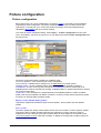
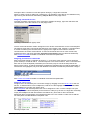
Table of Contents
Overview
......................................................................................1
Contents
...................................................................................................................................
of help file
1
Using
...................................................................................................................................
this help file
2
Quick start and concepts
......................................................................................4
Quickstart
................................................................................................................................... 4
Basic
...................................................................................................................................
programming terms and elements
11
DMX
...................................................................................................................................
addresses and links
14
Cross
...................................................................................................................................
fixture-type compatible effects
15
Scene
...................................................................................................................................
and fade times
15
Hardware configuration
and setup
......................................................................................16
Hardware
...................................................................................................................................
setup
16
Lightjockey
...................................................................................................................................
Software License
17
USB
...................................................................................................................................
DMX Interfaces
17
Configuration
.......................................................................................................................................................... 18
XLR
...................................................................................................................................
cable connnections
18
Updating
...................................................................................................................................
the driver for the USB DMX interface
19
Audio
................................................................................................................................... 19
Audio setup
.......................................................................................................................................................... 19
Audio CD..........................................................................................................................................................
control
20
Audio CD-ROM
..........................................................................................................................................................
trouble shooing
21
MIDI
................................................................................................................................... 22
External
...................................................................................................................................
control devices
22
The LightJockey
desktop
......................................................................................24
Main
...................................................................................................................................
desktop window
24
Configuring
...................................................................................................................................
the desktop
25
Desktop
...................................................................................................................................
main menu
27
Main system
..........................................................................................................................................................
m enu
27
Deleting
.........................................................................................................................................................
multiple data files
27
Using .........................................................................................................................................................
the data restore option
28
Main setup
..........................................................................................................................................................
m enu
29
System
.........................................................................................................................................................
preferences
30
Startup
.........................................................................................................................................................
options
32
Default
.........................................................................................................................................................
DMX output
33
Main view..........................................................................................................................................................
m enu
33
The unassigned
.........................................................................................................................................................
fixtures list
34
Tool...................................................................................................................................
and status-bars
34
Sequence/cue
..........................................................................................................................................................
tool bar
34
Cue list tool
..........................................................................................................................................................
bar
35
LightJockey
..........................................................................................................................................................
Offline Visualizer tool bar
36
Fixture tool
..........................................................................................................................................................
bar
36
Status bar.......................................................................................................................................................... 37
Fixture
...................................................................................................................................
icon popup
38
LightJockey Help
I
LightJockey Help file - (C) Martin Professional 2010
DMX
...................................................................................................................................
output monitor
39
User libraries ......................................................................................42
User
...................................................................................................................................
libraries
42
Backup
...................................................................................................................................
& restore
44
Fixture configuration
......................................................................................46
Fixture
...................................................................................................................................
configuration
46
Configuration
...................................................................................................................................
warnings
50
Copy
...................................................................................................................................
from fixture
51
Clear
...................................................................................................................................
fixture data
52
Applying
...................................................................................................................................
default DMX to new fixtures
53
Customizing
...................................................................................................................................
built-in fixture profiles
53
The select
..........................................................................................................................................................
bitm ap dialog
56
Controlling and......................................................................................58
programming fixtures
Selecting
...................................................................................................................................
fixtures for control and programming
58
Selecting..........................................................................................................................................................
fixtures on the desktop
58
Next/previous
..........................................................................................................................................................
fixture selection
59
Fixture groups
.......................................................................................................................................................... 60
Using
...................................................................................................................................
generic DMX profiles
62
Generic DMX
..........................................................................................................................................................
profiles
62
The generic
..........................................................................................................................................................
DMX control
64
The RGB pack
..........................................................................................................................................................
color control
67
Fixture
...................................................................................................................................
controls
69
Fade state
..........................................................................................................................................................
buttons
70
Fixture control
..........................................................................................................................................................
elem ents
71
User palettes
.......................................................................................................................................................... 73
Intensity ..........................................................................................................................................................
control
74
Intensity
.........................................................................................................................................................
controls for built in profiles
74
Intensity
.........................................................................................................................................................
controls for user defined profiles
74
Movem ent
..........................................................................................................................................................
and position control
75
Position
.........................................................................................................................................................
control
75
Position
.........................................................................................................................................................
fan out
78
Movement
.........................................................................................................................................................
macros
79
Movement macro
.........................................................................................................................................
engine
79
Bézier shapes
......................................................................................................................................... 80
Auto delay control
......................................................................................................................................... 81
Position
.........................................................................................................................................................
presets
83
Non pan/tilt
.........................................................................................................................................................
movement controls
84
Color control
.......................................................................................................................................................... 85
Color controls
.........................................................................................................................................................
for built in profiles
85
Color controls
.........................................................................................................................................................
for user defined profiles
87
Gobo control
.......................................................................................................................................................... 88
Gobo .........................................................................................................................................................
controls for built in profiles
88
Gobo .........................................................................................................................................................
controls for user defined profiles
90
Beam control
.......................................................................................................................................................... 90
Beam.........................................................................................................................................................
controls for built in fixtures
90
Beam.........................................................................................................................................................
controls for user defined profiles
91
Effect control
.......................................................................................................................................................... 91
Effect.........................................................................................................................................................
controls for built in profiles
91
Effect.........................................................................................................................................................
controls for user defined profiles
93
Extended..........................................................................................................................................................
controls
94
LightJockey Help
II
LightJockey Help file - (C) Martin Professional 2010
Extended
.........................................................................................................................................................
controls for built in profiles
94
Extended
.........................................................................................................................................................
controls for user defined profiles
95
Lam p controls
.......................................................................................................................................................... 95
Lamp .........................................................................................................................................................
controls for built in fixtures
95
Lamp .........................................................................................................................................................
controls for user defined profiles
96
Reset control
.......................................................................................................................................................... 97
Resetting
.........................................................................................................................................................
fixtures, built in profiles
97
Resetting
.........................................................................................................................................................
fixtures, user defined profiles
97
Smoke machines
and hazers
......................................................................................99
Controlling
...................................................................................................................................
DMX smoke machines and hazers
99
The
...................................................................................................................................
smoke control
100
The sequence......................................................................................102
control
The
...................................................................................................................................
sequence control
102
Save
...................................................................................................................................
sequence dialog
103
List
...................................................................................................................................
of sequences
105
Inserting
...................................................................................................................................
scenes
106
Deleting
...................................................................................................................................
scenes
106
Sequence
...................................................................................................................................
blind mode
107
Snapshot
...................................................................................................................................
and recording from DMX output
107
Sequence
...................................................................................................................................
fades
109
The cue control
......................................................................................111
The
...................................................................................................................................
cue control
111
Save
...................................................................................................................................
cue dialog
114
List
...................................................................................................................................
of cues
115
Cue pages
.......................................................................................................................................................... 118
Cue
...................................................................................................................................
control columns and slot colors
120
Modifying
...................................................................................................................................
sequence slot labels
121
Trigging
...................................................................................................................................
sequences in the cue
122
Sequence
...................................................................................................................................
slot loop options
123
Cue
...................................................................................................................................
time control
124
Cue
...................................................................................................................................
macro control
125
Transparent
...................................................................................................................................
cues
127
Sequence
...................................................................................................................................
intensities
127
The
...................................................................................................................................
cue builder
128
The generic DMX
macro
......................................................................................131
Generic
...................................................................................................................................
DMX macros
131
The
...................................................................................................................................
Generic DMX macro editor
134
The
...................................................................................................................................
macro shapes lists
136
Macro
...................................................................................................................................
visualization and tracking panel
137
The
...................................................................................................................................
fixture channel list
138
Generic
...................................................................................................................................
macro parameters
139
Generic
...................................................................................................................................
macro delays
140
LightJockey Help
III
LightJockey Help file - (C) Martin Professional 2010
Save
...................................................................................................................................
macro dialog
142
Select
...................................................................................................................................
macro list
143
The background
cue
......................................................................................145
Using
...................................................................................................................................
the background cue
145
List
...................................................................................................................................
of background cues
147
The cue list control
......................................................................................148
The
...................................................................................................................................
cue list control
148
Save
...................................................................................................................................
cue list dialog
154
List
...................................................................................................................................
of cue lists
154
Cue
...................................................................................................................................
list commands
155
Using
...................................................................................................................................
time code in cue lists
157
MIDI/SMPTE
...................................................................................................................................
time code
159
Launching
...................................................................................................................................
external programs from the cue list
161
Using
...................................................................................................................................
the LightJockey MediaPlayer
161
Playing
...................................................................................................................................
multiple, simultaneous media files from the cue list
163
Using
...................................................................................................................................
Winamp for digital audio playback
164
Winamp
...................................................................................................................................
time code issues
165
The statics control
......................................................................................167
Static
...................................................................................................................................
merge and replace modes
168
Using audio input
......................................................................................170
Global functions
......................................................................................173
Global
...................................................................................................................................
intensity control
173
Blackout/restore
.......................................................................................................................................................... 173
Master intensity
..........................................................................................................................................................
control
173
Freeze
...................................................................................................................................
output
176
Offline
...................................................................................................................................
/ Online switch
176
Follow
...................................................................................................................................
spot function
176
Fixture
...................................................................................................................................
solo function
178
Global
...................................................................................................................................
patching
178
Global patch
..........................................................................................................................................................
dialog
178
HTP groups
......................................................................................................................................................... 181
Hotkeys
......................................................................................182
Using
...................................................................................................................................
hotkeys
182
Hotkey
...................................................................................................................................
functions
183
External control
......................................................................................189
Fingers
...................................................................................................................................
for LightJockey
189
Introduction
..........................................................................................................................................................
to Fingers
189
Fingers ..........................................................................................................................................................
setup
189
Fingers ..........................................................................................................................................................
controls overview
191
Fingers ..........................................................................................................................................................
status panel
194
LightJockey Help
IV
LightJockey Help file - (C) Martin Professional 2010
Configuring
..........................................................................................................................................................
and using the function buttons
194
Configuring
..........................................................................................................................................................
and using the scroll buttons
196
Configuring
..........................................................................................................................................................
and using the cue slot button functions
197
Configuring
..........................................................................................................................................................
and using fader and bum p functions
198
Configuring
..........................................................................................................................................................
and using jog-w heel functions
201
Fingers ..........................................................................................................................................................
m ulti select m ode
201
Virtual Fingers
.......................................................................................................................................................... 202
Using
...................................................................................................................................
the 2532 direct access controller
203
2532 direct
..........................................................................................................................................................
access
203
The 2532..........................................................................................................................................................
layout
203
Configuring
..........................................................................................................................................................
the 2532 controller
204
Printing ..........................................................................................................................................................
the 2532 configuration
208
Em ulating
..........................................................................................................................................................
the 2532
208
Using
...................................................................................................................................
DMX in
209
DMX in translation
.......................................................................................................................................................... 214
Editing
.........................................................................................................................................................
translation tables
216
Using
...................................................................................................................................
MIDI in
217
Using
...................................................................................................................................
the 2518 controller via RS-232
219
2518 controller
..........................................................................................................................................................
via RS-232
219
2518 controller
..........................................................................................................................................................
via RS-232, m ode 2
220
2518 controller
..........................................................................................................................................................
via RS-232, m ode 1
221
MC-X
...................................................................................................................................
remote control
222
RS-232
...................................................................................................................................
remote control
223
User definable......................................................................................225
fixture profiles
The
...................................................................................................................................
user definable fixtures profiles
225
Scanner
...................................................................................................................................
1 profile
225
Configuring
..........................................................................................................................................................
the Scanner 1 profile
225
Defining..........................................................................................................................................................
the Scanner 1 profile
226
Defining..........................................................................................................................................................
Scanner 1 intensity control
226
Defining..........................................................................................................................................................
Scanner 1 pan & tilt control
228
Defining..........................................................................................................................................................
Scanner 1 color control
229
Defining..........................................................................................................................................................
Scanner 1 gobo control
230
Defining..........................................................................................................................................................
Scanner 1 level control
231
Color
...................................................................................................................................
Scroller 1
232
User Definable
..........................................................................................................................................................
Fixtures - Color Scroller 1
232
Defining..........................................................................................................................................................
the Color Scroller Profile
232
Generic
...................................................................................................................................
fixture type 2 profile
233
Defining..........................................................................................................................................................
the generic fixture 2 profile
233
Applying..........................................................................................................................................................
profile data to m ultiple fixtures
235
User definable
..........................................................................................................................................................
dynam ic functions
235
User definable
..........................................................................................................................................................
static functions
236
User definable
..........................................................................................................................................................
palettes
237
The fixture
..........................................................................................................................................................
info tab
240
The intensity
..........................................................................................................................................................
& lam p tab
242
The pan..........................................................................................................................................................
& tilt tab
244
The fixed
..........................................................................................................................................................
color tab
247
The CMY..........................................................................................................................................................
& RGB tab
247
The gobo
..........................................................................................................................................................
tab
249
The beam
..........................................................................................................................................................
tab
250
The effects
..........................................................................................................................................................
tab
251
The special
..........................................................................................................................................................
tab
251
The levels
..........................................................................................................................................................
tab
253
The Offline
..........................................................................................................................................................
Visualizer tab
254
LightJockey Help
V
LightJockey Help file - (C) Martin Professional 2010
Creating..........................................................................................................................................................
custom bitm aps for palette controls
255
Creating..........................................................................................................................................................
custom bitm aps for fixture icons
256
Importing
...................................................................................................................................
and exporting profiles
256
Im porting
..........................................................................................................................................................
user defined fixture profiles
256
Exporting
..........................................................................................................................................................
user defined fixture profiles
257
External
...................................................................................................................................
application/device profile plug in
258
Real time visualizing
......................................................................................260
Martin
...................................................................................................................................
Showdesigner MC Edition
260
Interfacing
...................................................................................................................................
with Capture
260
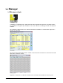
LJ Manager
......................................................................................263
LJ
...................................................................................................................................
Manager plugin
263
The 2510 playback
controller
......................................................................................265
Using
...................................................................................................................................
the 2510 playback controller with LightJockey
265
Creating
...................................................................................................................................
a sequence list for the 2510 controller
266
Generating
...................................................................................................................................
the 2510 download file
269
Downloading
...................................................................................................................................
the 2510 download file
270
Using
...................................................................................................................................
the 2510 for playback
270
2510
...................................................................................................................................
memory test
271
Binary
...................................................................................................................................
2510 files
272
Creating download files for the 2518
controller
......................................................................................273
Release notes......................................................................................275
Version
...................................................................................................................................
2.100
275
Version
...................................................................................................................................
2.95
275
Version
...................................................................................................................................
2.9
275
Version
...................................................................................................................................
2.8
276
Version
...................................................................................................................................
2.7
276
Version
...................................................................................................................................
2.6
278
Version
...................................................................................................................................
2.5
283
Version
...................................................................................................................................
2.3
286
Version
...................................................................................................................................
2.2
287
Version
...................................................................................................................................
2.1
289
Version
...................................................................................................................................
2.0
291
LightJockey Help
VI
LightJockey Help file - (C) Martin Professional 2010
Overview
Contents of help file
See Release notes
See Using this help file
Contents - overview
Basic programming terms and elements
Programming quick start
Hardware setup
Fixture configuration
User definable fixtures and creating new profiles
DMX smoke machines and hazers
DMX addresses and links
Main desktop window
Configuring the desktop
Desktop main menu
Selecting fixtures
Tool and status bars
Fixture controls
The generic DMX control
The sequence control
The cue control
The cue list control
The background cue
The statics control
Generic DMX macros
Follow spot functions
Global patch
Default DMX output
HTP groups
Startup options
Using audio-in
Using time code in cue lists
Using the LightJockey MediaPlayer
LightJockey Help
1
LightJockey Help file - (C) Martin Professional 2010
Backup and restore
Using the data restore option
Hotkeys
Fingers for LightJockey
2532 direct access
DMX In remote control
MIDI In remote control
Martin MC-X remote control
Martin 2518 Controller via RS-232
Using the 2510 playback controller.
RS232 remote control
External devices and applications
Controlling RGB fixtures
Martin Showdesigner MC Edition
LJ manager (plug-in)
Interfacing with Capture
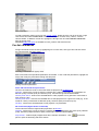
Using this help file
Changing the help file
the LightJockey help file may be available in different languages. To select between different help files
use Select Help file from the main help menu.
Please note that any non-English help-files may not document the latest changes and updates (see
LightJockey Help
2
LightJockey Help file - (C) Martin Professional 2010
Release Notes for the helpfile in question).
While an updated version of the English help file is always shipped with LightJockey it may be
necessary to update the non-English help files when they become available.
The latest releases are available from the Martin Website at http://www.martin.com/service/default.
asp?product=lightjockey and the latest beta release usually via the LightJockey forum at www.martin.
com/forum/
Topic help from within LightJockey
Most windows and controls in LightJockey has a Help entry in the local menu. If present, clicking
Help opens the help file on a help topic that relates to the function(s) of the window/control itself.
The help file as PDF
The help file is also supplied in PDF format on the CD. The latest PDF version may be downloaded via
the LightJockey end-user forum at www.martin.com/forum/.
Adobe Acrobat reader or another PDF reader application is required to read PDF documents - at the
time of writing this a free version of the Acrobat reader can be downloaded from www.Adobe.com.
A print out of the entire help file should be made via the PDF file.
LightJockey Help
3
LightJockey Help file - (C) Martin Professional 2010
Quick start and concepts
Quickstart
Programming LightJockey
Introduction to programming
This short introduction will help you get started using the Martin LightJockey quickly. It assumes that
you have some basic experience programming moving lights and are familiar with Windows. Additional
information is available in this on-line "Help" documentation.
If you are a Martin 3032 programmer
Programming with the LightJockey is similar in many ways to programming with the 3032 Controller.
Fade times and the Off/Snap/Fade control, however, will be new features to 3032 programmers.
The best way to learn your way around the LightJockey is to experiment. As you try the controls, be
aware that clicking with the left and right mouse buttons often do different things. Note: depending on
software version, screens and button names may differ from those shown here.
LightJockey Desktop
Configuring fixtures
The first step after configuring the hardware is to select and address your lighting fixtures in the
Fixture Configuration window. In the following example, the LightJockey is set up to control 2 MAC
600s.
1.
2.
3.
4.
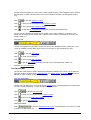
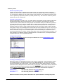
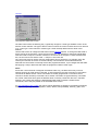
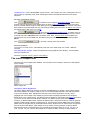
Choose Setup > Fixture Configuration from the main menu.
Select "MAC 600 (mode 2/4)" from the list of Available Fixture Types (found under the Martin
Manufacturer heading). Drag and drop it on line 1. Add another MAC 600 to line 2. (Multiple
fixtures can also be added using the Add (fixture name) button.)
If the addresses are already set on the fixtures, click the fixture, select the DMX link it's on, and
enter its address in the DMX Address field.
If you want the controller to automatically assign addresses, click Auto Address. Click Find
LightJockey Help
4
LightJockey Help file - (C) Martin Professional 2010
5.
6.
7.
Addresses and then click Ok. Remember to set the addresses on the fixtures to match the
LightJockey's fixture configuration.
Click the first MAC 600. Type "Left" in the Fixture Username field.
Click the second MAC 600 and name it "Right."
Save the configuration and close the window.
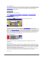
Configuring the desktop
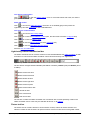
Lighting fixtures are represented by icons on the desktop. To create and place icons you drag fixtures
from the Unassigned Fixtures list to the desktop. Icons can be organized any way you like on multiple
pages or "tabs."
1. The list of unassigned fixtures is displayed on the desktop automatically. It can also be opened
by selecting View > Unassigned Fixtures from the main menu.
2. Drag the MAC 600s to the desktop.
3. Right-click on the desktop. Select Icons > Auto Arrange. Click OK. Additional menus pop up
when you right-click on the icons but we are not concerned with these now.
Key LightJockey concepts
Understanding these concepts is critical for successful programming with the Light-Jockey. Don't
LightJockey Help
5
LightJockey Help file - (C) Martin Professional 2010
worry if they are new to you, the programming example that follows is designed to illustrate them and
they will make more sense once you have been through it.
Cues, sequences, and scenes
A light show is typically divided into cues that you program and then play back from the list of
available cues. The LightJockey also supports cue playback several external units such as the Martin
2532 Direct Access Controller.
A cue 'points' to up to 12 sequences that run together in parallel. In addition to these pointers, cues
have some additional sequence timing and loop options.
A sequence is a set of scenes that run one after the other. A sequence can have from 1 to
999 scenes.
A scene is a set of instructions for selected fixtures. These instructions are made up of a static
command, a fade time, and a scene time. A static command is one or more instructions such as
"insert the red filter" or "rotate the triangle gobo counterclockwise." Fade time is the time it takes, for
example, for the color to change from blue to red. Scene time is simply how long the scene lasts
before the next scene in the sequence is executed. If scene time is greater than fade time, the fixture
fades to the position and stops.
Current cues and current sequences
To program cues and sequences you either create new ones or load existing ones using standard
Windows techniques such as dragging and dropping. Once loaded or created from new they become
the current cue or current sequence.
The current cue is displayed differently from the current sequence. The action of the current cue is
shown by changes in the relevant control windows. The pan/tilt cursor in the movement window, for
instance, slides back and forth to show a pan movement. This feature lets you see the program
without actual fixtures.
The controls for effects programmed in the current sequence, however, stand still so you don't have to
catch a moving target as you work. The pan/tilt cursor, to take the previous example, stops moving
when you load the movement sequence onto the desktop. To see the sequence run again you have to
clear it from the desktop by loading another sequence or clicking New/Clear Sequence on the
Sequence toolbar.
Bottom to top execution
Understanding the order of execution in the cue is vital for successful programming. The Light-Jockey
executes the current sequence first and then executes the current cue from bottom (sequence 12) to
top (sequence 1). When two sequences contain instructions for the same effect, the sequence
closest to the bottom has priority; instructions in the sequence closest to the top are not executed.
Off/Snap/Fade control
Most effect controls have an Off/Snap/Fade (O/S/F) button. In the default setting, the button is red and
displays "Off." Clicking the red Off button once turns it into a yellow "Snap" button. Clicking again
turns it into a green "Fade" button. Some controls, such as
the Lamp Control, have Off and Snap only.
When an effect's O/S/F button is Off, the control sends no instructions. This allows a lower-priority
sequence to control that effect. It does not turn off the effect itself. The dimmer O/S/F button must be
Off in sequence 10, for example, if you want to program a
dimmer command in sequence 9 or below.
When you set an effect's O/S/F button to Snap, the effect moves at maximum speed.
When you set an effect's O/S/F button to Fade, the effect's speed is determined by the fade time. To
program a scene with a 10-second pan movement, you would first define the movement with the
cursor, then set the Pan O/S/F button to Fade, and finally set the scene and fade times to 10
seconds.
Setting an effect's O/S/F button to Snap or Fade overrides all programming for that effect in higher
sequences in the cue. Leave the button on Off (the default) unless you are programming a command.
Striking lamps
Most Martin fixtures with discharge lamps, also known as arc lamps, must be struck (turned on) from
LightJockey Help
6
LightJockey Help file - (C) Martin Professional 2010
the controller. There are three ways to do this:
Use the LightJockey's automatic lamp-strike feature. This is recommended and is described in the
following example.
Program a "lamp on" cue. This is not recommended because Martin fixtures use the same DMX
channel for lamp and shutter control. Therefore, the lamp-on command will be overridden by any
higher-priority sequence with a shutter command. If you choose to program a "lamp on" cue, turn
on the lamps one at a time with 3 - 5 second intervals to avoid excessive voltage drop and current
draw.
Strike a lamp manually by selecting it, clicking the Lamp button on the fixture tool-bar, and clicking
Power On in the Lamp Control dialog. Depending on the fixture, the Lamp Control may also allow
you to turn off the lamp.
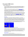
Example: Programming a cue
The following example, in which you program a simple cue for 2 MAC 600s, demonstrates the basic
steps and concepts involved in programming. To keep you focus on the screen, it is suggested that
you program the first cue without fixtures attached.
The screens shots show how your screen will look if you follow the steps correctly.
Step I: Strike lamps
This step only applies if you have actual fixtures connected to the controller.
1. Configure 2 MAC 600s and place them on the desktop.
2. Turn on the MAC 600s, set them to mode 4, and set their addresses to match the LightJockey
fixture configuration.
3. Choose System > Auto Strike Lamps from the main menu. Click Stop when the lamps have
struck.
Step II: Program shutter/dimmer sequence
In this step you program a sequence to open the shutters and set the dimmers to 20%.
1. Configure 2 MAC 600s and place them on the desktop if you have not done so.
2. Click New/Clear Sequence on the Sequence toolbar. The new (blank) sequence is indicated by a
gray Sequence name field.
3. Click both MAC 600s to select them. The fixture icon caption is blue when the fixture is not
selected and red when it is selected.
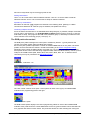
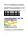
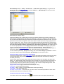
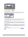
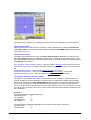
4. Click Show Fixture Controls on the Fixture toolbar (see page 1). Arrange the control windows any
way like by dragging them on the desktop. Since you will not be using the Beam control in this
example, you can close it to make more room on the desktop. Individual controls can be opened
and closed as needed by clicking buttons on the Fixture toolbar.
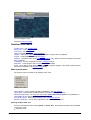
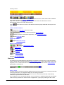
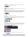
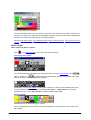
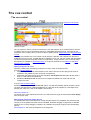
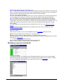
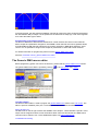
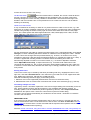
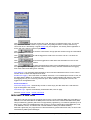
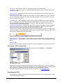
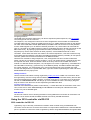
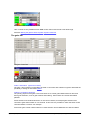
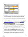
5. Find the Intensity dialog (see below). Click the shutter control. Three things happen: "Shutter
Closed" changes to "Shutter Open," the shutter O/S/F button automatically changes to Snap,
and the Sequence Name field in the Sequence toolbar changes from gray to yellow, indicating
that the new (blank) sequence has been changed.
6. Drag the dimmer level to 20%. Click the dimmer O/S/F button twice to Snap.
7. Verify that your Intensity control looks like the one above and that the O/S/F buttons
in all other controls are off.
8. Click Save Sequence in the Sequence toolbar. Type "20% dimmer" in the dialog's
Sequence Name field. Click Save as New Sequence or press Enter.
LightJockey Help
7
LightJockey Help file - (C) Martin Professional 2010
Step III: Add sequence to Cue
Checking "Add Sequence to Current Cue" in the Save Sequence dialog would have automatically
added the sequence to the current cue when saving. Windows techniques such as drag and drop can
also be used to add, delete, and rearrange items in lists.
1. Click List of Sequences on the Sequence toolbar.
2. Click View Cue Control on the Cue toolbar.
3. Drag the "20% dimmer" sequence to position 1 in the cue. (If drag mode is not enabled, choose
Preferences > Drag mode from the Select Sequence dialog menu.)
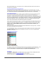
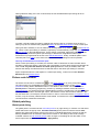
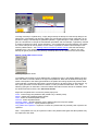
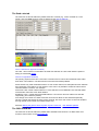
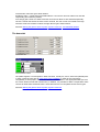
Step IV: Program CMY sequence
The next sequence is a CMY (cyan, magenta, yellow) color chase with 3 scenes. In the first scene,
cyan fades in and yellow, which comes in scene 3, fades out. In the second scene, cyan fades out
and magenta fades in. Finally, magenta fades out and yellow fades in. The scene and fade times for
each scene is set to three seconds for a smooth continuous effect.
1. Close the cue editing and sequence list windows.
2. Click New/Clear Sequence on the Sequence toolbar.
3. Make sure both MAC 600s are selected: a fixture is selected when the icon caption is red. Drag
and drop sequences to cues.
4. Place the cursor over the cyan fader and drag it to 100%. The O/S/F button automatically
changes to Fade.
5.
6.
7.
Click View Sequence Control in the Sequence toolbar.
Click the "Synchronize Scene and Fade Times" box. Set the scene (and fade) time to 3
seconds.
Click Add Scene in the Sequence dialog.
LightJockey Help
8
LightJockey Help file - (C) Martin Professional 2010
8.
Drag the Cyan fader to 0%. Drag the Magenta fader to 100%.
9. Click Add Scene in the Sequence dialog.
10. Drag the Magenta fader to 0% and the Yellow fader to 100%.
11. Now you need to change scene 1 to fade out yellow. Scroll to scene 1 of 3 by clicking Next
Scene (not Add Scene) in the dialog.
12. Yellow is already at 0% so you only need to click its O/S/F button to Fade.
13. Click Save Sequence in the Sequence dialog or toolbar.
14. Click the "Clear after Save" and "Add Sequence to Current Cue" boxes in the Save Sequence
dialog.
15. Type "CMY chase" in the name field.
16. Click Save as New Sequence or press Enter. Notice how the CMY faders move once the
sequence has been saved, cleared, and added to the current cue.
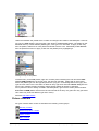
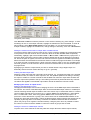
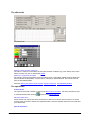
Step V: Program movement sequence
The LightJockey features a sophisticated engine for generating pan/tilt movements. The effects engine
is not described here but detailed information is available in the on-line help. In the first two
sequences, both fixtures were programmed together to do the same thing. In this sequence you
program each fixture individually to move in opposite directions.
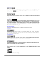
1.
2.
3.
To program "Left" MAC 600, select it and deselect the "Right" MAC 600.
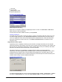
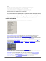
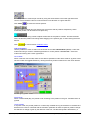
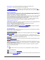
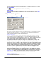
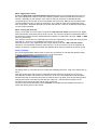
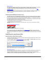
If the pan/tilt control window, shown below, is not open, click Movement on the Fixture toolbar.
Drag the movement cursor to the middle of the top-right quadrant. Click the Pan and the Tilt O/S/
LightJockey Help
9
LightJockey Help file - (C) Martin Professional 2010
F buttons twice to Snap.
Click the "Left" MAC 600 to deselect it; select the "Right" MAC 600.
Drag the movement cursor to the middle of the top-right quadrant.
Click the Pan O/S/F button and the Tilt O/S/F button to Snap.
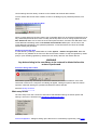
Open the Sequence Control if it is closed by clicking View Sequence Control. Set the scene time
to 2 seconds.
8. Click Add Scene in the Sequence dialog. Click Synchronize Scene and Fade Times. Set the
scene (and fade) time to 15 seconds.
9. Drag the movement cursor to the middle of the top-right quadrant. Click the Pan O/S/F button to
Fade.
10. Click the "Right" MAC 600 to deselect. Select the "Left" one.
11. Drag the movement cursor to the top-left quadrant and click the Pan O/S/F button to Fade.
12. Click Save Sequence on the Sequence toolbar. Type "Pan" in the Sequence Name field. Click the
"Clear after Save" and "Add Sequence to Current Cue" boxes. Click Save as New Sequence or
press Enter.
4.
5.
6.
7.
If you programmed the sequence as described, the movement cursor will move slowly from left to right
if when you select the "Left" MAC 600 and from right to left when you select the "Right" one.
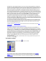
Step VI: Edit movement sequence
This step demonstrates how to edit a programmed sequence. Here you edit the pan sequence to
black out both fixtures in the first scene.
1. Click List of Sequences on the Sequence toolbar.
2. Drag the "Pan" sequence to the desktop. Close the sequence list. Notice that the cursor in the
Movement control stopped moving.
3. Open the Sequence Control if it is closed. Click Next Scene to advance to scene 1 of 2.
4. Select both MAC 600s.
5. Click the shutter control in the Intensity dialog. It changes from "Shutter Open" to "Shutter
Closed." Click, if necessary, to set the shutter O/S/F button to Snap.
6. Click Save Sequence on the Sequence toolbar or in the Sequence dialog. To save the changes to
the sequence, click Save Sequence or press Enter. Click OK to confirm.
Step VI: Save the cue
Cues are handed much like sequences.
1. Click Save Cue on the Cue toolbar.
2. Type "M600 CMY pan" in the Cue Name field.
3. Click Save New or press Enter.
Step VII: Edit the cue
This step demonstrates how sequence order effects cue playback. Look at the Intensity control: the
shutter closes for 2 seconds because of the command in the pan sequence. This sequence has the
highest priority because it is closest to the bottom. When you put the 20% dimmer sequence
underneath the pan sequence, the 20% dimmer sequence takes priority and keeps the shutter open
all the time. With a little planning, you can create different looks using the same sequences just by
changing their order.
1. Click New/Clear Cue on the Cue toolbar to clear the cue from the desktop. (This is not required; it
just helps demonstrate how to load cues.)
2. Click List of Cues on the Cue toolbar.
3. Drag the "M600 CMY pan" cue to the desktop. Its name appears in the Cue name field and the
cue begins to run. Close the list of cues to make room on the desktop.
4. Click View Cue Control on the Cue toolbar.
5. Drag the "20% dimmer" sequence from position 1 to position 4. Select Move Sequence from the
popup dialog.
6. Click Save Cue in the Edit Cue window or on the Cue toolbar.
7. Click Save. Click OK in the confirmation dialog.
8. Look at the Intensity control: the shutter now stays open all the time.
LightJockey Help
10
LightJockey Help file - (C) Martin Professional 2010
Additional cue operations
When editing cues, remember that the current sequence has highest priority. Normal cue execution
resumes when the current sequence is cleared. Note too that to synchronize the sequences in the
current cue, you must clear the cue and reload it onto the desktop.
To create a new cue and/or clear the current one, click New/Clear Cue.
To load a cue, click List of Cues and drag it from the List of Cues to the desktop. Click View Cue
Control to open the Edit Cue window. Here, sequences can be added, removed, rearranged,
loaded, etc.
To adjust cue timing, open the Cue Edit window and click Cue Times at the bottom. The cue
master fader adjusts times (as a percent) for all sequences set to "CUE" time. Setting a
sequence fader to another value overrides the master cue fader.
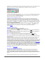
Basic programming terms and elements
Fixtures
This term is used throughout the LightJockey to describe the 'equipment' that the LightJockey can
control. The term may not only be confined to lighting fixtures, but everything that might be controlled
from LightJockey via DMX protocol, such as smoke machines or motor control.
Fixture profiles and protocols
Controlling fixtures via DMX is actually not a very 'intelligent' method of control. There are (for various
reasons, some of them good reasons) no industry standards for commands like "go to red" or "move
to home position". This means that each type of fixture has it's own set of command values - the
fixture DMX protocol. On generics DMX consoles, usually equipped with faders to set values, it is
necessary for the programmer to know the correct command values to send and also which channel
or address to send these value to. Most modern control systems implement more or less
sophisticated fixture 'personalities' to hide the protocols from the end-user. LightJockey implements
graphical 'personalities' or profiles for most DMX capable fixtures, this means that the user does not
need to know anything about DMX values or addresses to program fixtures. While not essential, a
good understanding of how the DMX protocol works is definitely an advantage when trying to get the
most out of LightJockey programming.
See also DMX addresses and links, Generic DMX fixtures, User definable fixture profiles
Scene
A scene is the most basic programming element in LightJockey. In other types of consoles and
controllers this is also known as a memory. Unlike most other consoles, LightJockey does not refer
to individual memories, scenes only exists as part of sequences (see later).
Each scene in LightJockey contains information for all fixtures and all their effects.
Usually, only a small number of the fixtures/effects will be programmed in a scene as LightJockey
offers methods to combine and layer several 'scenes' to create a final output (e.g. in a cue). So most
of the time an effect will probably be "unused" or "off" in a given scene (see off/snap/fade).
A good analogy to a scene in LightJockey is a single picture frame on a roll of film. As the picture
frame, a scene only contains static information, so a scene cannot contain both red and blue color
commands for the same color wheel on the same fixture. Like the film, the 'animation' or changes
happen when the film progresses through the individual picture frames to form a movie. This is what
happens when one scene is replaced by another scene, as in a sequence or when replacing one cue
with another cue.
As mentioned, the scene only contains static commands, note however that not all static commands
to fixtures result in a static 'expression'.
For example a command to a fixture to strobe or rotate it's color wheel will result in a 'dynamic'
expression - in this case the static command specifies a strobe-frequency or rotation speed but the
fixture performs the actual dynamic.
LightJockey Help
11
LightJockey Help file - (C) Martin Professional 2010
Another notable exception which is dynamic in expression are the movement macros that moves the
light around in geometric patterns. Although the information to move the light in a circle has a
dynamic expression (the movement in a circle) - the parameters that determine the 'dynamics' are still
static within the scene.
Sequence
A sequence is the cornerstone of programming in LightJockey. A sequence consists of one or more
scenes chained together in a sequential order. If the sequence contains more than one scene, the
sequence can 'animate' the fixtures by executing scenes with different contents, like the film strip with
different picture frames. The default behavior for a sequence when it reaches the last scene, is to loop
back to the first scene to get a continuous execution of the sequence.
A very simplified example is a sequence containing 3 scenes:
Scene 1 instructs a fixture equipped with a color wheel to go to red, scene 2 instructs the fixture to go
to yellow and in scene 3 the fixture is instructed to go to green. When this sequence is played back
in the default loop mode, the sequence will 'animate' the color of the fixture through the 3 colors, and
after scene 3 it will loop back and start with scene 1 and the red color again.
Scene and Fade times
The sequence also contains parameters that dictate how the animation is supposed to take place.
First of all there is the scene time. In the previous example, a scene time of 1 second for all scenes
would have LightJockey advancing through the sequence, with each scene being replaced by the next
scene after 1 second of 'on time'. Scene times can be set individually for each scene in the sequence
with the sequence control, e.g. scene 1 may have a scene time of 1 second, while scenes 2 and 3
may have a scene time of 0.5 and 2 seconds respectively.
The sequence also contains a fade time for each scene. The fade time dictates how long time the
physical transition will take from the position (e.g. color wheel position) programmed in the previous
scene, to the position programmed in the current scene.
Here the film analogy might be used again. A film shot showing a person walking from one side of the
scene to the other side requires 'a lot' of individual pictures in between the two positions to get
'smooth' movement. The way to make making slow, smooth movements like this with LightJockey is
to program the two end points (colors in the example) in two scenes, and then let LightJockey
calculate all the positions (pictures in the analogy) in between the two end points. This is exactly
what using fade time and fading an effects does.
With the previous color example, setting a fade time of 3 second for each scene, would mean that
each color change takes 3 seconds. The way this works is that LightJockey calculates all the
possible positions between the two colors, and outputs these values at a calculated rate so that the
fixture moves the color wheel from one position to the next in one smooth movement taking exactly 3
seconds (note, some fixtures will not allow slow transitions between colors or other types of effects this is a restriction of the fixture's DMX protocol, not LightJockey).
Note that in order for an effect to fade from one position to the next, the fade state of that effect must
be set to fade. See off/snap/fade
A sequence does not have to contain more than one scene - in this case, the sequence is called
static sequence. While the scene time no longer is relevant since there will be no progression in the
sequence, the fade time still controls the transition time from the previous effect position (whatever
that was) to the one programmed into the scene.
See also Scene and fade times, Sequence control
Cues
A cue is a construction that contains up to 12 sequences to be executed run in parallel. Although
LightJockey allows playback of single sequences, the cue offers much more flexibility in terms of
dynamic and combination options.
LightJockey Help
12
LightJockey Help file - (C) Martin Professional 2010
It is important to understand that the cue only contains references to the sequence, not the actual
sequences themselves. This means that if a sequence is edited to a new contents, this change will
take effect in ALL cues that contains a reference to this sequence. It also means that it is not
necessary to re-save cues just because the sequence has been changed, the changes will implement
automatically.
It is normally not desirable to program every fixture and effect into the same scene, even to obtain the
'complete look'. The reason for this, is that by combining a number of sequences each with elements
that together forms the complete look, it is much easier to re-use some of these elements to obtain
other looks. It is also the only way of obtaining simultaneous different fade times on different effects in
the same fixture, as the sequence only allows one fade time pr scene, e.g when combining a slow
color change with a fast speed intensity chase.
An example is a very simple cue consisting of 3 sequences:
- Sequence 1 contains instructions to all fixtures output light with full intensity (static sequence)
- Sequence 2 contains information to all fixtures to fade between red, green and blue colors (nonstatic sequence)
- Sequence 3 contains information that moves the fixtures beams around in a pattern (non-static
sequence)
The combined result has the fixtures moving around in the complex pattern, all changing between the
colors and all with full intensity.
By replacing sequence 1 with another static sequence that orders the fixtures to strobe on full
intensity, a different expression has been created. Still the same colors changes, still the same
movements, but now the fixtures are strobing rather than having full intensity. To obtain the same
result in a single sequence, all scenes would have to be edited so that they contain a strobe
command and not full intensity for all fixtures.
Another example would be to have the original cue running, but two of the fixtures should point to a
specific location in open white at 50% intensity, while all the other fixtures still moves the beam
around in the pattern and changing colors.
Without the cue construction, the only way to do this would be to edit the two fixtures in every scene
of the sequence, creating a new sequence with this look particular look.
However, by using the cue and its rules of priority (see below), it is possible to write just a single
static sequence instructing just these two fixtures to go to the position in open white with the right
amount of intensity. This static sequence is then added at a priority position within the cue and takes
control over only the programmed fixtures - the rest still runs the original cue since they are not at all
affected by the new sequence.
The way the priority works within the cue is not related to fixtures, rater to individual fixtures/effects
(DMX control channels to be precise). How to program the sequences and use the cue is very much
up to individual tastes, and most likely also fixture types and fixture count.
Some programmers programs complete fixtures, or groups of fixtures into sequences including all
desired effects for these fixtures. They then use the cue to combine different groups of fixtures, each
group of fixtures contained in it's 'own' sequence. Other programmers swear to modularity and only
programs single effects into sequences. E.g. color information in one sequence, gobo information in
another, movement information in a third sequence and so on. By combining these sequences in the
cue they create complete looks.
Most programmers however, tends to use some from both methods. There are no rules governing how
to use the cue - in the end it is up to personal preferences.
See cue control for more details.
LightJockey Help
13
LightJockey Help file - (C) Martin Professional 2010
Cue list
The cue list offers a way to playback cues in a pre-determined order. The cue list may be
synchronized to internal PC clock for elapsed time between cues or to time code from a CD-ROM
drive or Windows Media files. It can also be executed manually using a 'go-button', if for example used
in a theatrical type of show where everything is planned and pre-programmed.
See cue list control for more details
The current sequence
It is important to understand that the LightJockey always contains a 'current sequence'. Think of the
current sequence as a 'holder' for sequences when editing a sequence. When saving a sequence, it is
always the current sequence that is being saved, and when loading an already saved sequence, the
sequence is being loaded 'into' the current sequence for editing.
In principle the current sequence always contributes to the final DMX output of the LightJockey however if the current sequence does not contain any 'instructions' (for example after a New Sequence
command has been executed) there will be no visible effect of the current sequences contribution to
the overall output.
The current cue
In the same way as the current sequence the LightJockey always have a current cue. The current cue
acts as a 'holder' for cues when editing, and when playing back cues, it is always done by loading
cues into the current cue. As with the current sequence, the current cue always contributes to the
final DMX output, but if the current cue contains no 'instructions' (no sequences or other elements) there will be no visible effect.
DMX addresses and links
DMX Addresses
To enable communication between the LightJockey and the fixtures, an address must be assigned to
each fixture. This address must also be set on the fixture itself - Martin fixtures has DIP-switches or
LED display panels for address settings.
When assigning DMX addresses keep in mind that fixtures usually uses several continuous
addresses, for example the Roboscan 918 uses 16 addresses. The first address is usually referred to
as the start-address. This is important to remember since it is not possible to 'share' addresses
between individual fixtures, so if the Roboscan 918 was given the start-address of 1, the next available
address would be 17 (1+16).
The DMX protocol defines a maximum of 512 addresses (or channels) so all fixtures must fit within
this address space.
There are two ways to assign an address to a fixture in LightJockey.
Set the address manually.
Use the address field in the upper right hand corner of the fixture configuration dialog. Use this method
to match addresses on fixtures that has already been given an address (on the fixture).
Use the "Auto Address" function.
This will prompt LightJockey to calculate addresses based on the fixtures selected and fixtures that
has already been assigned an address. Use this approach when fixtures have not yet been addressed
(on the fixture). There are a few exceptions where the auto address will not work - see details in the
Fixture Configuration help topic.
Link
Link is a term that describes the physical connection from the controller to the fixtures (and between
the fixtures). Since the DMX protocol allows only 512 channels on one link, the only way to add more
channels to a system is to increase the number of links (physical connections). Depending on what
DMX transmitter hardware is in use in the installation, one or more links may be available for
connecting fixtures. Links are numbered 1-4 and when addressing the fixtures, make sure to specify
LightJockey Help
14
LightJockey Help file - (C) Martin Professional 2010
which link the fixture is connected to.
Cross fixture-type compatible effects
Some fixture effects are cross-fixture type compatible. This means that changes to a cross type
compatible effect on the master fixture will also change the effects on the selected slave fixtures, even
if they are not of the same type as the master fixture but still support the same type of effect. For
example, applying 50% intensity to the master fixture will also set 50% intensity on the slave fixtures.
The following effects are usully cross-fixture type compatible although exceptions may exist:
Intensity, strobe, shutter (intensity), pan and tilt positions and movement macros, CMY and RGB, iris,
focus, (variable) zoom, lamp on/off commands, fixture reset, levels (for generic DMX fixture profiles)
Other effects such as gobo or fixed colors are not cross fixture-type compatible.
Scene and fade times
Each scene in a sequence has its own scene time and fade time, both can be set in the Sequence
control. The scene time defines how long each scene is active before the sequence advances to the
next scene within the sequence. If the sequence contains only one scene, the scene time doesn't
have any real effect since the sequence never advances to a new scene. The scene time defaults to a
value of 1.00 seconds.
Fade time dictates the way a scene changes effects from its previous position (DMX value) to the
position(DMX value) stored within the scene.
In order for an effect transition to be controlled by the fade time, the effect must be programmed with
the fade state set to fade. If the effect is programmed with the fade state to snap, the effect will simply
snap to the new position regardless of the fade time set in the scene. The fade time defaults to a
value of 0.05 seconds.
It is possible to set a fade time that is higher than the scene time. In this case the transition to the
new value in the scene is never finished.
LightJockey Help
15
LightJockey Help file - (C) Martin Professional 2010
Hardware configuration and setup
Hardware setup
In order for LightJockey to recognize PC or external hardware such as transmitter interfaces or direct
access controllers, they must first be configured using the hardware setup dialog. The dialog is
accessed through the main Setup menu (Setup/Hardware Setup).
The hardware setup dialog
The dialog locates different types of hardware and associated settings on different tabs:
DMX Hardware - configure and setup DMX transmitter and receiver hardware - see Configuring USB
DMX Interface
XLR Cable connections - connecting the serial links to the interfaces. Converting 3 pin XLR to 5 pin
XLR and phase reversing XLR cables - see XLR cable connnections
Audio - configure and setup Audio related hardware and software - see Audio setup
MIDI - configure and setup MIDI related hardware and software - see MIDI
External control devices - configure and setup peripheral hardware that connects via RS-232 or DMX-in
- see External control devices
LightJockey Help
16
LightJockey Help file - (C) Martin Professional 2010
Lightjockey Software License
The bottom of the DMX Hardware Setup indicates the current license level of LightJockey.
Protection device:
Indicates if the Martin OneKey with the LightJockey license is connected to the PC.
The key always needs to be plugged in before starting LightJockey. Inserting the key when
LightJockey is running requires to close and restart the application.
LightJockey license:
Full license allows 4 DMX Universes Out, 1x DMX In, 2048Ch., maximum of 3 USB devices can
be used by LightJockey
Limited license (Martin OneKey found but no license present): Interfaces can be configured, but
only Universe 1, Channels 1-128 and DMX IN are active.
No License (no Martin OneKey found): Unable to configure devices and no DMX Output
USB DMX Interfaces
DMX transmitter hardware is configured using the DMX hardware tab in the hardware setup dialog.
LightJockey supports the following types of DMX transmitter/receiver hardware:
Martin Universal USB DMX interface
Martin USB Duo DMX Interface
Both devices support 1024 DMX channels out or 512 DMX channels out + 512 DMX channels in.
Up to 3 interfaces may be connected (4x Out, 1x In)
LightJockey Help
17
LightJockey Help file - (C) Martin Professional 2010
Configuration
Once installation of Windows USB driver(s) is completed and the interface(s) is plugged in, start up
LightJockey and go to the hardware setup Main Menu ->Setup
Configured DMX hardware list
Identifying and naming the Universal USB/DMX interfaces
If you click on an ID button in the list, the interface will respond by blinking green/orange on the right
LED.
Assigning Universe to Ports
Each USB Interface needs to have its ports assigned to the desired DMX Universe or to DMX In.
Port A is the left port when looking at the front of the interface, Port B the right port.
The configuration is stored inside the USB interface.
See also XLR cable connections
XLR cable connnections
Connecting the DMX link(s)
All LightJockey DMX transmitter hardware is configured as pin 1 to shield, pin 2 to cold and pin 3 to
hot. See below for notes on 3 to 5 pin XLR converters and phase-reversing cables (used with older
Martin fixtures and possibly fixtures from other manufacturers).
Always remember to terminate the end of the DMX links with a 120-ohm terminating plug.
3 Pin to 5 pin XLR converters and phase reversing cables.
LightJockey Help
18
LightJockey Help file - (C) Martin Professional 2010
Updating the driver for the USB DMX interface
When updating the driver for the USB DMX interface as prompted by an in-program notification or
release notes please follow the following procedure:
1. Shut down LightJockey.
2. Unplug all USB DMX interfaces.
3. To update the driver run the driver installation program located in the <LightJockey Installation
Path>\HardwareDrivers\ and follow any onscreen prompts. If updating from a downloaded driver
update, please follow the instructions given for the download.
4. Once the driver setup application has finished, attach each individual USB DMX interface one at a
time wait for 10 seconds and allow Windows Found New Hardware Wizard to complete for each
interface if required (the wizard may not appear in all circumstances).
5. Restart LightJockey and check that the interfaces are recognized by selecting Setup/Hardware
Setup from the main menu.
Please note that updating drivers will most likely require a user account with administrator access
(depending on Windows version)
Audio
Audio setup
Use the Audio tab to configure and select audio options for LightJockey.
Audio options
The Audio Analyzer
The Audio analyzer program enables LightJockey to use audio input via a sound card to trig
sequences in the cue. See using audio in and trigging sequences in the cue for more information.
LightJockey Help
19
LightJockey Help file - (C) Martin Professional 2010
CD-Audio
Enabling CD-Audio allows LightJockey to control a CD-ROM drive for audio CD play back. It also
allows LightJockey to take time code from the audio CD to synchronize the cue list to audio CD time
code. See Audio CD Control and Using time code in cue lists for more information. Note that in newer
Windows versions application control of CD-ROM drives has become... errhhh.. troublesome. If
possible, copy the CD tracks to hard disk (use any 'CD ripping' application - for example Windows
Media Player to copy the track to hard disk) and use the LightJockey MediaPlayer to playback the
digital audio file rather than using the CD directly.
Digital Audio Playback
While not strictly a piece of hardware, LightJockey is able to connect to Winamp for playback of
digital audio (MP3, Wav, etc..). The time code from the digital audio may be used to synchronize
sound and light in the cue list. Note that LightJockey connects with Winamp 2 (version 2.74) only.
See uising Winamp for digital audio and using time code in cue lists for more information. In order for
LightJockey to automatically start Winamp when required (through in the cue list), the complete path
to the Winamp executable must be entered in the 'Path to Winamp' field. Click
the Winamp.exe file.
and navigate to
LightJockey MediaPlayer
The LightJockey MediaPlayer is a separate module distributed with LightJockey that encapsulates
core functions of Windows Media Player. LJ MediaPlayer may be used to playback different media file
formats, including digital audio and video files. The MediaPlayer requires Windows Media Player
version 6.0+ installed on the PC. The LJ MediaPlayer is exclusively used in cue list context and
requires no initial configuration. For more details see LightJockey MediaPlayer
Audio CD control
In order to get access to the audio functions from the CD-ROM drive, the drive must be configured in
the hardware setup dialog.
After configuration and a restart of LightJockey, the CD audio control is available via
list tool bar
on the cue
Audio CD control
The CD control functions like any domestic CD player, play, forward, next track etc. The drag bars
may also be used to set the playing position. When the CD time-code is used to drive a cue list
elapsed disc time is always used.
Analogue vs. digital playback in Windows 2000 and XP
Windows 2000 and XP offer the option to playback CD audio mode - which may be a great option if
there is no analogue connection from the CD/DVD drive to the sound card. The response time from
the digital mode driver seems to be much faster than the analogue driver.
However, experience shows that in digital mode the 'true' time code update rate may actually be much
slower than in analogue mode - the digital audio driver simply just returns the same time code for
sequential time code requests.
The best way to check for the 'real' time code update rate is to open an empty cue list. Then open the
LightJockey Help
20
LightJockey Help file - (C) Martin Professional 2010
time code log panel in CD time code mode, and hold down the [Ctrl] key for about 2-3 seconds to
continuously log time codes from the CD drive (*). Then add the time codes to the cue list and check
the time between individual time codes.
(*) It may be necessary to set keyboard repetition rate to max to log as many time codes as possible.
Preferences menu
View Track Info - Expand the control to show individual track time information.
CD Device Settings, Status Timer Interval - Set a rate between 50ms to 1000 ms or select minimum
(fastest) - default value is 100 ms.
Minimum depends on system, but is usually around 5 to 7 ms. The lower the value the more often the
time code is read from the CD-ROM, allowing for a more precise time code triggering of the cue list.
However some Windows versions/CD-ROM drive combinations take a very long time (25-100+ ms) to
return time code for the CD-ROM. Setting a low value on a 'slow' system may slow down the PC a
low, even to the point of choking the PC. The caption of the CD control continuously displays the time
taken for the last status polling - setting a time polling time at about or lower than the average polling
time will cause the system to slow down a lot.
Tests have shown that the way Windows 2000 and XP drives the CD-ROM drive seems much more
effective than Windows 9X (although this may not apply to all systems) - if CD audio is a crucial
element of a Windows 9X system and response time from the drive is high (50ms+), it may be a good
idea to upgrade the PC to Windows 2000 or XP.
Commands
Even though Microsoft has published a command interface for use of CD-ROM, not all Windows
versions/drive combinations seem to work according to the command set - if the drive doesn't work as
expected try set or clear the following options (by default all options are on).
Use Stop as Pause Command - The control issues a stop rather than a pause command (some drives
does not seem to recognize the pause command).
Pause before cuing position - Some drives ignores a position command if they are already playing.
Check this option to issue a pause command before re-positioning.
Invalidate Timecode when stopped - some drives return invalid or wrong time code when stopped
(which may cause the cue list to behave strangely). Check this option to automatically invalidate time
(set to 0) code when the drive is stopped or paused.
See also audio CD-ROM trouble-shooting
Audio CD-ROM trouble shooing
No Disc or Drive Not Ready
No disc is inserted into the CD-ROM Drive or system is still initializing
Cannot open drive tray
Some CD-ROM drives will return a tray-open status even when the tray is closed if there is no CD
present in the drive. On "Eject" LightJockey will try to "Close the tray that is already closed. Shift
click on the eject button to force the tray open if necessary.
Message: CDROM drive already in use. The drive cannot be shared between applications
Another application is already using the CD-ROM drive. Most likely it is used by the Windows CD Player (check in the Windows taskbar). Often this will happen when "CD insert notification" is enabled
on the CD-ROM drive, auto-starting the Windows CD Player application whenever a new Audio CD is
inserted.
There are two ways of fixing this problem. The first fix is to disable the auto insert notification. This
may be done by right-clicking on the "my computer" icon on the desktop. Select "properties" and
"device manager". Select "properties" for the particular CD-ROM Drive, and disable "auto insert
notification" on the "settings" tab. Please note that this will disable the auto-start feature for any CDROM.
LightJockey Help
21
LightJockey Help file - (C) Martin Professional 2010
The second is to remove the file-type association of the audio CD. The exact method may depend
somewhat on what version of windows is installed, and what type of desktop manager is used. In
general, open any folder and select the "File type" tab. Find the "AudioCD" entries in the "registered
file types" and remove the entry.
Message CD-ROM drive not found
LightJockey cannot detect the presence of a CD-ROM drive - please check Windows installation.
See also audio CD control
MIDI
Select MIDI options from the MIDI tab.
MIDI tab
MIDI Note Commands
A number of functions including latching cues or flashing sequences may be remotely controlled via a
MIDI interface. To enable MIDI remote control of LightJockey via MIDI, enable the MIDI In function on
the MIDI In tab. For more details on the MIDI note implementation see MIDI In.
MIDI Timecode
MIDI time code (MTC) may be used as a time source for cue lists. To enable a MIDI time code
interface, select it from the MIDI device list via the lower right-hand corner (Select from list then click
Select Device). Note that in order for LightJockey to recognize the MIDI device it must be installed
with working Windows drivers.
The MTC Timeout Value determines the time it takes before an MTC driven cuelist times out after
MTC transmission has stopped. Normally, the default value of 0.5 sec is fine, but special
circumstances may make it necessary to increase the timeout value.
External control devices
2532 Direct Access keyboard
Before the 2532 Direct Access keyboard may be used with LightJockey it needs to be configured.
Enable the 2532 Direct Access and then select the appropriate serial port (COM1-COM4). It is not
necessary (or recommended) to enable to enable the 2532 and select a serial port in order to use the
2532 control in virtual mode (using the control without a 2532 physically connected).
NOTE: The 2532 must have at least version 3.0 software in order to work with LightJockey.
Martin 2518 (via RS-232)
Connects the Martin 2518 controller via RS-232. Since the connection is via RS-232 it is possible to
connect the 2518 without additional hardware (except an available RS-232 port and suitable cable).
MC-X Controller
As the MC-X controller uses DMX to communicate with LightJockey, it is only useable with an
LightJockey Help
22
LightJockey Help file - (C) Martin Professional 2010
appropriate hardware interface that supports DMX in.
Note that if the MC-X interface is enabled, normal DMX in functionality is suspended.
See MC-X Remote Controller for details on setup and use.
Fingers for LightJockey
Fingers connection is enabled and configured from the main menu (Fingers)
See also RS-232 remote interface for controlling LightJockey through a RS-232 connection.
LightJockey Help
23
LightJockey Help file - (C) Martin Professional 2010
The LightJockey desktop
Main desktop window
The LightJock ey desk top
The LightJockey Desktop is devided into 3 separate areas. At the top (below the main desktop menu)
is a tool bar area, in the middle is the fixture area where configured fixtures are illustrated by Icons,
and at the bottom is the status bar.
The desktop window it self is an ordinary Windows-style window that may be minimized, maximized
or resized at will. On multiple monitor systems the Desktop window can reside on any monitor.
Besides the desktop window LightJockey has a number of different dialogs, lists and other types of
controls. All these are launched in separate, independent windows (as the fixture controls in the
screenshot above) - these windows may be moved freely on the whole Windows desktop, even
outside the regular LightJockey desktop, and LightJockey remembers the position where the window
was placed the last time and uses this position when the window is opened again (it is possible to set
a restriction on where the windows are located when re-opened).
On multi-monitor systems, use the extra desktop space to keep the LightJockey desktop on one
monitor, or even a par of one monitor, while using some or the rest of the Windows desktop area for
the individual control windows.
Desktop tabs
Fixtures are represented on the desktop by icons that may be placed anywhere on multiple pages or
"tabs" This allows fixtures to be organized according to personal preferences. To create or edit tabs,
select tabs from the popup menu. Create a new tab by clicking add. Edit or delete the tab by
selecting the tab from the list, and then click the appropriate button.
Placing fixture icons on the desktop
When a new fixture has been configured it's icon is not yet assigned to any tab on the desktop. A
fixture is not programmable until it has been placed on the desktop - to place the fixture, drag it from
the unassigned fixtures list that opens automatically when new fixtures are configured, and drop it on
a suitable place on the desktop. Alternatively click place all in the menu to place all unassigned
fixtures on the current tab.
Moving fixture icons
Select Icons -> Move all from the desktop popup menu. This will switch all icons into move mode. It
LightJockey Help
24
LightJockey Help file - (C) Martin Professional 2010
is now possible to move the icons around on the current tab by dragging the icon to the new position.
Icons in move mode cannot be selected for programming, so once the icons are placed deselect
move all again on the desktop menu.
To place a fixture icon on a specific tab
If the fixture is still in the unassigned fixures list, activate the tab, and drag the fixture onto the
desktop. To move a fixture from one tab to the other, right-click the fixture icon to unassign the icon.
The unassigned window will automatically open up. Activate the relevant tab and drag the fixture to the
desktop.
See also configuring the desktop, desktop main menu, selecting fixtures, tool and status bars, fixture
icon popup
Configuring the desktop
Right-click on an empty spot the desktop to access the desktop popup menu.
Desktop popup menu
Desk top popup menu
Select All Programmed - selects all fixtures programmed in the current sequence/scene. Requires
Show programmed fixtures option enabled (see below).
Deselect Odd Fixtures - deselects all fixtures with odd fixture number
Deselect Even Fixtures - deselects all fixtures with even fixture number
Fixture Groups - opens the fixture groups dialog.
See also selecting fixtures
Icons Menu
Icons menu
Style - this option selects between two different styles of fixture icons:
Fixed Size : All Icons have the same base size.
Image Size : Icons are sized according to the size of the image assigned to the fixture icon and icon
caption (fixture user name).
Move all - toggles all fixture icons between move mode (gray caption) and normal mode. For arranging
the icons on the desktop, see below. When in move mode the icons cannot be used for fixture
selection.
Auto-arrange Icons- this will auto arrange all the fixture icons on the current tab, according to fixture
type or fixture number.
Show Programmed Fixtures - with this option enabled each fixture icon will show a colored rectangle
when the fixture is programmed (scene/sequence contains data) in the current sequence. Green if the
fixture is programmed in the current scene, and cyan if the fixture as been programmed in any other
scene in the current sequence. The function is off by default. Note that checking the sequence for
programmed status runs in a separate low priority process, so especially for larger sequences or very
busy systems, the status may take a few seconds to update.
LightJockey Help
25
LightJockey Help file - (C) Martin Professional 2010
Fixture programmed in current scene
Fixture programmed in current sequence
Unassign Icons - unassign all icons on the current tab, or just the selected icons.
Desktop
Desk top menu
Tabs - use this dialog to create, rename or delete desktop tabs.
Grid - use a grid to assist in positioning fixture icons on the desktop.
Desk top grid dialog
Image - It is possible to use bitmaps (pictures) as wallpaper on the desktop. Click Image, locate the
required bitmap then click Ok. Note that only standard Windows bitmap files (.bmp files) may be
used. Also note that large images may requires a lot of CPU time when re-drawing and may slow
down the GUI of LightJockey considerably. Use the image dialog to clear an earlier assigned image
and to set the following image options:
Stretch Image - sizes the image so that it fills up the desktop.
Center Image - centers the image on the desktop. Does not resize image.
Note: It is not possible to show wallpaper image and the grid at the same time.
LightJockey Help
26
LightJockey Help file - (C) Martin Professional 2010
Custom wallpaper image
See also fixture icon popup
Desktop main menu
System menu - see system menu
Setup menu - see setup menu
View menu - see view menu
Offline-Visualizer menu - see Offline Visualizer
Capture - settings for Capture link - only visible when a Capture link is configured.
Fingers - configuration and settings for Fingers
Generics - provides access to the generic DMX control - only visible if at least one Generic fixture has
been configured
LJ-Manager - access configuration for the LJ Manager plug in.
Download - create program data for 2510 and 2518 controllers
Audio - use to launch Audio Analyzer or Digital Audio playback program. Only visible if either function
have been configured in the hardware setup dialog.
Main system menu
The System menu is located on the desktop main menu.
Main system menu
User Libraries - used to create and select userlibraries. See user libraries
Delete Files- used to delete multiple data files. See deleting multiple data files
Restore Program Data - see using the data restore option. Note that this option is only available if a
restore data set has previously been created.
Auto Strike Lamps - start auto-strike lamp cycle - see startup options
Restart LightJockey - closes down LightJockey and restarts a new session.
Deleting multiple data files
From the main desktop menu select System -> delete files. The following file types may be deleted
(select from menu):
Sequence Files
LightJockey Help
27
LightJockey Help file - (C) Martin Professional 2010
Cue Files
cue list Files
Background cue files
Generic DMX Macros
Selecting and deleting files
Delete sequence files dialog
Select one or more files to delete by highlighting the files in the list. Use Select All or Clear All to
select all files or clear all selections.
Once the files are marked, delete the files by clicking Delete.
Checking Sequences
The Delete Sequences dialog contains an option to check if the sequence files are used in any cues.
To check through sequences, click Check Used Sequences. Used sequences are marked with a
'Yes' in the rightmost column and unused sequences are marked with a 'No'. When the sequences
have been checked (may take a little time), click Mark Unused Sequences to highlight unused
sequences only.
Using the data restore option
LightJockey has the capability of backing up the contents of a single users library and on demand
restore the backed up users library to the exact same contents as when the backup was created. The
backup data may be password protected so that the backup data can only be created by authorized
personnel. The backup data is stored locally on the PC hard disk.
This backup function is not intended as a general method to backup and restore data from
LightJockey, but rather targeted towards installation types such as fixed installations in clubs where
inexperienced users have access to various settings and programming. The option offers a quick
method for the inexperienced user to restore LightJockey to the exact point at where the backup was
created without having to locate individual backup files.
Creating the backup data
Create restore data dialog
To create the backup data set, open the system preferences dialog, setup -> preferences -> system
and select the Data Restore tab. Then click Create Restore Data. A complete snapshot of the
LightJockey Help
28
LightJockey Help file - (C) Martin Professional 2010
current settings and user library contents is now created and stored for later retrieval.
Once a restore data set has been created, access to the dialog may be password protected, see
below.
Password Protecting the Backup Data
Password dialog
When a backup data set has been created, the create data dialog may be password protected so that
only authorized personnel has access to modify the backup data. To set or change a password click
New Password. Make sure to enter the exact same password twice, and then click Ok. Back in the
Create Restore Data dialog check the Password Protect Restore File option. The access to the
Create Restore Data dialog is now password protected. A new restore data set cannot be created
without entering the password.
Restoring the backup data
In order restore a previously created data set, select System -> Restore Program Data. Note that
the option is only available in the menu if a data set has been created. Accept the LightJockey restart
prompt. Upon restarting LightJockey restores the user library data from the restore data set.
WARNING
Any data existing in the user library to be restored is deleted before the
restore is performed.
File Error during data restore
After restart LightJockey will attempt to restore the data found in the restore data file. If the data
restore file is found to be corrupt this error dialog will appear, offering an option to abort the restore
operation. Note that aborting the operation will delete the restore data file.
See also backup & restore
Main setup menu
The main setup menu has a number of sub-menus that facilitates settings of various options and
settings. The menu is located in the LightJockey desktop main menu.
Main setup menu
Fixture Configuration - dialog for setting up the fixtures to be controlled by LightJockey. See fixture
LightJockey Help
29
LightJockey Help file - (C) Martin Professional 2010
configuration
Hardware Setup - dialog for selecting and configuring hardware options. See hardware setup
Global Patch - dialog for modifying the default source of DMX output data. See global patch
Preferences - dialog for setting system preferences. See preferences -> system, preferences -> start
up and preferences -> default DMX output
Hotkeys - dialog for modifying hotkey setup and global enable/disable of hotkeys. See hotkeys
System preferences
The system preferences dialog allow settings of various user library or system wide options. The
access is through the main menu, select Setup -> Preferences -> System.
System Preferences dialog
System Settings tab
Enable bitmap cache - enabling this function will give an increased performance when drawing
controls, but it also uses Windows system resources which may be limited on some systems;
especially Windows 9X or ME. If only one instance of the LightJockey application is running, this will
not be a problem, but if Windows throws up a warning that system resources are getting low, make
sure to deselect this option.
Allow freeze output - enables or disables the users access to the freeze output function.
Allow sequence blind mode - enables or disables the sequence blind mode
Allow offline switch - enables or disables the On/Offline switch
Allow fixture solo selection - enables or disables the fixture solo selection function
Open controls on Windows desktop - normally most controls retain their last position when re-opened.
When this option is enabled, all controls are forced to open within the boundaries of the Windows
desktop. Checking this option ensures that if controls have been placed outside the visible area of the
Windows desktop (e.g. when lowering the video resolution) they will become visible when re-opening.
Note for multi-monitor systems: Windows desktop is defined as the upper left corner of the primary
display to the lower right corner of the last display. However, if monitors are driven in different screen
resolutions, the desktop height (or width if displays are vertically configured) is defined as the height
(or width) of the primary display. This may cause problems if secondary displays are driven at a
resolution different from the primary displays - in this case it is probably the best to disable the option.
Open controls on LightJockey desktop - when this option is enabled, all controls open within the
boundaries of the LightJockey desktop. Use this option if controls have been placed outside the visible
area of the Windows desktop (e.g. when lowering the video resolution).
Start LightJockey on Secondary Monitor - check this option to force LightJockey to start up on the
secondary monitor in a multi monitor system. Setting is ignored if only one monitor is detected.
Restore LightJockey desktop on startup (Size/Position) - when checked, the LightJockey desktop will
default to the same size and position and size it had when LightJockey was previously closed down. If
not enabled LJ will maximize on the designated monitor.
LightJockey Help
30
LightJockey Help file - (C) Martin Professional 2010
Warnings tab
Sequence/Cue Modified - enable to prompt a confirmation box every time before a modified sequence
or cue is overwritten by a clear or load command. Note that the cue modified warning will not be
shown if the cue was loaded as a transparent cue.
Overwrite Sequence/Cue - enable to prompt a confirmation box each time before a saving on top of an
already saved sequence or cue.
Show Blackout Warning - enable this to show a warning when blackout or fade-in or fade-out is active.
Click Cancel on the warning dialog to restore from blackout or fade modes.
Show Freeze Warning - when enabled, a warning is shown when DMX output is frozen.
Show Offline Warning - when enabled, a warning is shown when DMX output is offline.
Confirm Close Program - enable this to show a confirmation dialog when LightJockey is closed.
Quick Save/Load tab - enable sequence/cue/cue list quick save/load.
When quick save/load is enabled, right-clicking
will re-save the current sequence, cue or cuelist
without using the save dialog (it requires that the sequence, cue or cuelist has previously been saved if not, the case the save dialog will appear as usual).
Likewise right-clicking on any
will re-load the current sequence, cue or cuelist (only if a
previously saved sequence or cue or cuelist is currently loaded)
External Links tab
External links - external links allows LightJockey to talk to other Martin Windows applications.
Normally, if not instructed otherwise, leave these options off.
The external links will only be enabled if transmitter hardware is detected.
Enable Offline Visualizer - enables communication to Offline Visualizer - there is normally no reason
to disable this setting other than for trouble shooting purposes. If the option is grayed out it means
that LightJockey cannot locate the Offline Visualizer installation.
Enable link to Sandnet - enables routing of DMX data through Sandnet (tm). Note that this option
requires that LightJockey DMX hardware is installed and configured as well as appropriate Sandnet
hardware and/or software. More information about Sandnet can (at the time of writing this) be found at
http://www.sandsys.com
LightJockey Help
31
LightJockey Help file - (C) Martin Professional 2010
Enable link to Capture - enables communication with the Capture Visualization application running on
the same or another networked PC - see interfacing with Capture for more information
Data Restore tab - see using the data restore option
Startup options
To access the startup dialog, select Setup/Preferences/Startup from the desktop main menu.
Startup options dialog
Auto Lamp-On - enabling this option will configure LightJockey to startup with a lamp-on cycle,
sending lamp-on commands to all fixtures that support a lamp-on command. Lamp-on commands are
sent to one fixture at a time with a delay of approx. 1 second to avoid a surge on the power line. Set
the duration of the power-on cycle to 1 to 5 minutes. If none of the configured fixtures support lampon, the cycle will be aborted. The power-on cycle will run before any auto-start programs are
executed. During the lamp on cycle a window will appear on the desktop, displaying the lamp-on
cycle progress. The cycle may be aborted at any point by clicking Stop. The auto-lamp on command
is also available under the desktop main system menu. When started from here cycle will continue
until canceled.
Auto lamp-on cycle
Load On Startup (programs auto-start) - these options enables LightJockey to automatically launch a
specific sequence, cue, cue list or background cue (BG cue) on startup. Click the relevant Select
button to select the sequence, cue, cue list or background cue to auto-start. Sequences and cue lists
requires a check mark in the Run check box to execute after load, else they will remain static.
Run Minimized - check to automatically to minimize LightJockey after start up as soon as all
initializations are done. This setting is useful if LightJockey has to run silently in the background with
LightJockey Help
32
LightJockey Help file - (C) Martin Professional 2010
other applications.
Show notes on startup - when enabled the built-in note pad will (Main Menu -> View -> Notes)
automatically be displayed when LightJockey starts up.
Auto Launch Programs - use this option to automatically launch external support programs as
LightJockey starts up. Click Browse to specify which programs to be launched. An example of a
support program that must be launched this way is the RS-232 remote program.
To clear a program from the list, highlight it, right click and select delete entry from the popup menu.
During startup LightJockey will make no attempt to check if the program is already running, neither
will the program automatically be shut down when LightJockey shuts down. If the file launched is not
an executable, eg. *.exe - it is up to the user to make sure that the data file is properly associated
with an executable. For example to launch an MP3 file, the .MP3 extension must be properly
associated with a program to playback MP3 files. If, for some reason, an automatically launched
program causes LightJockey to crash or lockup before the entry can be removed from the list, the
program entries may be manually removed from the startup.ini file located in the LightJockey
installation folder.
Default DMX output
By default LightJockey defaults to a value of 0 for all DMX output channels when they are not
programmed - some fixture profiles may cause other default values to be used. By customizing the
default values, it is often easier to create a good basis for programming. The new defaults may contain
values causes a fixtures to home (center) on pan and tilt, or opens the shutter on fixtures equipped
with separate shutter and dimmer, so it won't be necessary both to open shutters and set intensity
values when programming. It may also be used to set a pre-heat value for fixtures running via dimmer
packs.
Use Current Scene - this option will record the output from the current scene. If values have already
been recorded for default output they will be included in the new default output, unless overwritten by
the contents of scene. This makes it possible to modify the default output just by programming the
modifications into the scene and then select 'use current scene'. Note : The default output cannot
contain presets or pan/tilt macros, if presets are present an error message will be displayed and the
new values will not be recorded.
Clear Default Output - this will reset the default output to all 0 values.
Main view menu
The menu is located under the desktop main menu.
Main view menu
Toolbars - use this submenu to toggle visibility of the various tool bars and the status bar.
Controls - use this submenu to display specific controls if the corresponding tool bar is not visible.
Unassigned Fixtures - use this to show the list of unassigned fixtures if the list was previously closed
(unassigned fixtures are fixtures which icons have not yet been placed on the desktop)
Notes - this will show a handy little notepad - the notes are saved in the current user library and can
be recalled at any time by selecting this menu item or by hotkey.
DMX Output - See DMX output monitor
Windows System Memory - displays information regarding Windows system memory. Used for
trouble shooting.
LightJockey Help
33
LightJockey Help file - (C) Martin Professional 2010
The unassigned fixtures list
When new fixtures have been configured using the fixture configuration dialog, a fixture icon
representing the individual fixture must be placed on the LightJockey desktop. Until the icon has been
placed, the fixture cannot be accessed from the desktop. When closing the fixture configuration
dialog, new fixtures are placed in a unassigned fixtures list. A dialog containing the list is
automatically displayed after configuration. The dialog may also be opened via View -> Unassigned
Fixtures.
Unassigned fixtures list
To place individual fixture icons on the desktop, drag the fixture from the list and drop it on the
desktop. Move Icons will automatically switch fixture icons in and out of icon move mode. Click
Unassign All to move remove all fixture icons from the desktop to unassigned list. Click Autoplace
All to place all icons on the current desktop tab ordered either by fixture type or fixture number.
Tool- and status-bars
The LightJockey desktop contains up to 4 tool bars with buttons for quick access to various functions.
There is also a statusbar with status information.
The sequence/cue tool bar has functions relating to the current sequence and the current cue.
The cue list tool bar has functions relating to the cue list, background cue and external control options
such as DMX in, MIDI, Audio CD and the 2532 Direct Access controller.
The fixture tool bar contains functions related to individual fixtures or groups of fixtures.
Finally the status bar contains various status information.
Any of the tool bars and status bar may be hidden to save desktop space, see main view menu
Sequence/cue tool bar
The left part of the tool bar contains buttons and information related to the current sequence, while the
right half contains buttons and information relating to the current cue.
Sequence tool bar
LightJockey Help
34
LightJockey Help file - (C) Martin Professional 2010
Current sequence displays the name of the current sequence (if any). The background turns yellow if
the sequence is 'active' (contains data). If the current sequence is empty, the background color is
gray.
Click
to view the sequence control.
Click
to clear the current sequence (see sequence control).
Click
to bring up the save sequence dialog.
Click
to open the list of sequences (to access previously saved sequences)
The tool bar also displays the current scene number in the current sequence, in the form of X:Y,
where X is the current scene number and Y the last scene number. If the sequence is empty, the
display shows '1:1'.
Cue tool bar
Current cue displays the name of the current cue (if any). The background turns yellow if the cue is
'active' or modified (contains data). If the current cue is empty, a gray background is used.
Click
to view the cue control.
Click
to clear the current cue.
Click
to bring up the save cue dialog.
Click
to get the list of cues (to browse existing cues or load a previously saved cue)
See also tool- and status-bars
Cue list tool bar
The left part of the tool bar contains buttons and information related to the current cue list while the
right part contains a button for the background cue, the statics control, audio CD control as well as
buttons for other, external control options.
The cue list tool bar
Current Cue List displays the name of the current cue list (if any). The background turns yellow if the
cue list is 'active' (executing) - if a gray background color is used.
Click
to view the cue list ontrol.
Click
to clear the current cue list (see cue list control).
Click
to bring up the save cue list dialog.
Click
to get the list of cue lists.
The bcue button
Click
to open the background cue control. If a background cue is active, the 'LED'
is green, if not the 'LED' is red
LightJockey Help
35
LightJockey Help file - (C) Martin Professional 2010
The statics control button
Click
to open the statics control. If one or more static entries are active, the 'LED' is
green, if not the LED is red.
Audio CD control
Click
to access the audio CD control. The button is not enabled (grayed out) unless the
LightJockey has been configured to use a CD-ROM Drive.
The external control buttons
Click
to access the MC-X setup dialog
Click
to access the 2518/RS232 control (note, the 2518 must have been configured first)
Click
to access the DMX in setup
Click
to view the MIDI in control (must be configured first)
Click
to view the 2532 direct access control
See also tool- and status-bars
LightJockey Offline Visualizer tool bar
The Offline Visualizer tool bar contains a button to launch/enable/disable the Offline Visualizer as well
as buttons to control various Offline Visualizer camera functions directly from LightJockey.
LightJock ey Offline Visualizer tool bar
The first button changes between Launch (start Offline Visualizer), Disable (hide) and Enable (show
if hidden).
default camera front view
default camera back view
default camera left view
default camera right view
default camera top view
default camera bottom view
camera full view
undo camera view
redo camera view
The last box contains the Offline Visualizer user camera list with cameras previously saved in the
Offline Visualizer scene. Views may be selected via this list or via hotkeys.
Fixture tool bar
The fixture tool bar contains buttons to access fixture controls, buttons for fixture selection and
selection modes as well as buttons for special controls such as smoke control or the global master
LightJockey Help
36
LightJockey Help file - (C) Martin Professional 2010
intensity control.
Fixture control selection
Click icons to access the individual fixture controls. Note that none of these buttons will be enabled
until at least one fixture is selected.
Right-click a button to open the corresponding control and close the other fixture controls
automatically (useful on a smaller desktop setup).
Click
click.
as a shortcut to show or hide all fixture controls (except extended controls) with one
Fixture selection buttons
Displays the fixture group selection window.
These buttons effects the desktop fixture selection.
Selects previous or next fixture respectively - see next/previous fixture
Selects fixture solo Mode
Follow spot button
toggles follow spot settings
Special controls buttons
/
see OffLine/OnLine switch
see freeze output
see smoke control
see blackout
see master intensity
See also tool- and status-bars
Status bar
The status bar is located below the main desktop. It displays the current time, system and system
memory status and the current level of the master intensity control. The bar also shows if the current
sequence, cue or cue list have been modified. Finally the trig information from the Audio Analyzer is
duplicated on the status bar.
Status bar
Memory status
Windows utilizes both physical memory (RAM) and virtual memory (hard disk). Accessing information
in the physical memory is magnitudes faster than accessing information
The indicator shows the percentage of used memory out of the total physical and virtual memory
available as reported back from Windows.
The % indication is not an absolute indicator; as more memory is needed Windows will automatically
reduce memory allocation for other functions or applications, typically by reducing the disk cache
LightJockey Help
37
LightJockey Help file - (C) Martin Professional 2010
size.
The color of the memory 'bar' indicates the amount of free physical memory left.
Green indicates more than 3 Megabytes physical memory free.
Yellow indicates between 2 and 3 Megabytes free physical memory free.
Orange indicates between 1 and 2 Megabytes free physical memory free.
Red indicates less than 1 Megabyte physical memory free.
As long as the indicator stays in green everything is fine. When the indicator goes through yellow and
orange, it indicates that there might be a slight loss of performance as there is little physical memory
left. A red indicator means very little or no physical memory free, probably causing a pretty poor
performance. it is still perfectly possible to run LightJockey even if the bar is red, as long as Windows
supplies enough virtual memory (and it usually does) - just expect for slower performance.
Fixture icon popup
To access this menu right-click on any of the fixture icons on the desktop.
Fixture icon popup
Select All programmed of this type - selects all fixtures of this type that are programmed in the
current scene. This function requires that the Show programmed fixtures option is enabled.
Select All of this Type - Deselect All of this Type - selects or de-selects all fixtures of the same type
as the 'clicked' fixture. The 'clicked' fixture automatically becomes master fixture when this function is
used.
Clear This Fixture - Clear Selected Fixtures - when clicked all fixture parameters are set to off in the
current scene in the current sequence.
Output generated by default DMX output, statics, the current cue or background cue is not affected.
Fixture Info - opens the fixture info panel
The info panel shows the fixtures DMX address and intensity group. If the profile contains DIPswitch
information the dipswitch shows the settings according to DMX address.
Fixture Notes - shows the fixture profile notes (same notes as shown in the fixture configuration)
DMX Output - opens the DMX output monitor aligned with the fixtures DMX address.
Fixture Configuration - opens the fixture configuration dialog with the fixture already selected.
Global Patch - opens the global patch dialog aligned on the fixtures DMX address.
LightJockey Help
38
LightJockey Help file - (C) Martin Professional 2010
Define Fixture Profile - opens the fixture profile dialog. This option is only available for user definable
fixtures.
Customize Fixture - opens the customize fixture palette dialog. This option is only available for
selected built-in fixture profiles.
Fixture Icon Menu
Unassign Icon - select to de-assign the icon from the current tab. The fixture will go back into the
unassigned fixtures list and can be re-placed on another tab. See configuring the desktop.
Move Icon - toggles the Icons 'movement' mode on and off. See configuring the desktop.
Align Icon - select the align command from the sub menu. The command will align the icons of all
selected fixtures to the current icon, e.g. selecting Icon Right will align the right side of all selected
icons to the current icon. Note, alignment will not work on icons that are in 'move' mode.
DMX output monitor
Open the monitor from desktop main menu -> view -> DMX Output
This window shows the actual DMX values output from LightJockey. To align the view with a particular
fixture, right click the fixture icon and select "DMX Output" from the popup menu.
DMX output monitor
Preferences menu
Highlight value changes - channels with changing values display values in red
Highlight used channels - channels that are in use by at least one fixture shows with gray background
Highlight selected Master fixture - channels in use by the master fixture is displayed with a green
background
Autoscroll to master fixture channels - the DMX monitor automatically scrolls to bring the channels of
the master fixture into view
Enable value overwrite - see below
Color scheme (background)
Gray background: DMX channel is used by at least one configured fixture
White background: DMX channel not used by any configured fixture
Green background: DMX channel used by selected master fixture
Color scheme (text)
LightJockey Help
39
LightJockey Help file - (C) Martin Professional 2010
Black text: unchanged DMX value (since the dialog was opened)
Red text: DMX value changed (since the dialog was opened)
Green text: DMX value overwritten
Control channel function
Highlight a specific output channel (click it's value) to see it's control function which is displayed in the
status bar at the bottom of the dialog.
Overwriting the DMX output values
Value overwrite enabled
The DMX output monitor allows DMX output values to be overwritten directly, without the need to
configure a fixture first. The output value is written directly to the DMX channel without regards to any
patches made with the global patch dialog. DMX output value overwriting must be enabled from the
Preferences menu. To overwrite DMX output values, select (highlight) the relevant DMX channel(s) and
use either the virtual fader or value field to enter/modify the DMX value. Click CLR to remove value
overwrite on the selected channels. DMX output channels that has their value overwritten displays the
value in green text.
Note: The DMX output can only be overwritten this way as long as the DMX output monitor is open
and DMX value overwriting is enabled. As soon as the monitor dialog is closed, the DMX values will
revert to non-overwritten values.
Searching DMX output channels
The DMX output monitor contains a tool that can be used to search for a specific DMX channel by
sending specific DMX values to specific channels in a search pattern. The tool is handy when trying to
locate DMX equipment that is connected and addressed but not yet configured and the address has
not been noted down. The tool uses a binary search algorithm that is capable of locating a specific
channel out of 2048 channels in a maximum of 11 'tries'. Click Tools in the menu to open the search
channel dialog and setup a channel search pattern.
LightJockey Help
40
LightJockey Help file - (C) Martin Professional 2010
Search channel dialog
During the search 'DMX on' and 'DMX off' values are sent to the channels in the search pattern. Modify
the DMX off and DMX on values value if necessary.
Setting up the search pattern
Un-check include link 1-4 to exclude fixtures on any specific link from the search. Un-check exclude
configured channels to include channels that are already in use by configured fixtures.Default options
will search on all 4 output links but exclude channels already used by configured channels.
Click Start to start the search
The search algorithm first applies the on value to all channels in the search pattern to check that the
device is included in the pattern at all. Subsequent searches will apply the on value to half the
channels in the search pattern and for each search iteration the number of channels in the search
pattern is halved according to the answer in the search prompt.
Search channel prompt
Click yes if the channel is on - no if the channel is off.
LightJockey Help
41
LightJockey Help file - (C) Martin Professional 2010
User libraries
User libraries
A user library contain all data that may be modified by the user, except for a few installation wide data
files such as hardware setup parameters. Using different libraries means that individual setups and
programs may be kept totally separate. Changing to a different user library requires a restart of
LightJockey.
After start up, LightJockey displays the current user library in the caption of the main window.
Main window caption. Current user library is "Default".
It is not possible to share or import data from different libraries. It is not advisable to manually copy or
move files from Windows explorer. The different data structures of LightJockey are often very
dependent on each other, and may not function if copied from different libraries. In any case don't ever
copy or move files while LightJockey is running - if, in special cases, it is necessary to copy or move
files, make sure that LightJockey is closed down first.
The User Library dialog is accessed from the main system menu (System -> User libraries..).
The user library dialog
The leftmost column of the list shows the (user-selectable) name of the library. The middle column
shows the Windows folder path while the rightmost column shows the creation date of the library.
The Default Library
The default user library is a special user library. It cannot be renamed or deleted. If the default library
is not present at startup, LightJockey will automatically create a new default library. Upon starting up
after initial installation LightJockey will always use the default library - further libraries must be created
by the user.
Creating a new user library
To create a new library, click Create New Library - this will prompt a new dialog.
New user library dialog
Type the new name of the new library. Check copy files to automaticallyl copy all data files from the
current to the new library, esentially creating a copy of the current library.
LightJockey Help
42
LightJockey Help file - (C) Martin Professional 2010
Switching to a different user library.
Highlight the library in the list and click Select User Library. In order to load the information from the
newly selected library, LightJockey needs to restart. Answer yes at the prompt to change the library,
or no to cancel.
Deleting a user library.
To delete a user library, highlight the library in the list and click Delete Library. Note that it is not
possible to delete the current library.
Renaming a library.
Highlight the library in the list and click Rename Library.
Moving user libraries between PCs
To move an entire library from one PC to another use the built in backup/restore function.
Starting LightJockey in a specific user library
LightJockey may be started up in a specific user library by adding a parameter to the startup
command (Windows shortcut). The syntax is <LightJockey> <U:[userlib_name]> where userlib_name
is the name of the folder where the specific user library is located. Use the information displayed in
the user library dialog to see the path where the individual user libraries are located.
When specifying the name only the 'last folder name' should be used, examples:
LightJockey U:user0001 - will start LightJockey in the user library located in
<LJinstallation>\user\user0001
LightJockey U:Default
- will start LightJockey in the default user library located in
<LJinstallation>\user\default
Note that some Windows versions may require the path a and name of the LightJockey executable to
be enclosed in quotes, eg:
Target: "C:\Program Files\Martin Professional\Martin LightJockey\LightJockey.exe" U:user002
LightJockey Help
43
LightJockey Help file - (C) Martin Professional 2010
Modifying a Windows shortcut to LightJock ey
See also backup & restore, using the data restore option
Backup & restore
LightJockey implements a function to backup and restore data from individual user libraries - it does
not implement functions to backup or restore the entire installation. To backup a complete installation
it is a good idea to use an application such as Winzip www.winzip.com to compress the backup into
one file or use the backup/restore function built into some versions of Windows. Note that restoring
from a backup completely replaces the existing contents of the user library.
Creating a backup
Select (highlight) the user library to backup from the list in the user libraries dialog. When creating a
backup of the current library make sure to close all LightJockey dialogs before backup - a number of
data files may not be properly updated until the corresponding dialogs are closed. Alternatively close
down LightJockey and re-start to make sure all relevant data has been saved.
Selecting a user library for back up (User library dialog)
LightJockey Help
44
LightJockey Help file - (C) Martin Professional 2010
Back up dialog
The backup dialog includes a small note pad to add notes to the backup file - the notes are embedded
into the backup file and can be used as reference when later searching through backup files. Click
Create Backup File to start creation of the backup file. The backup procedure will collect and
compress the entire contents and structure of the selected user library into one backup file. Once the
file has been created save it using the standard Windows file dialog.
Using floppy disks for backup files
The backup file is saved as one large file, and it is the users responsibility that the media to which the
backup file is saved has sufficiently space to hold the file. However since the backup file is
compressed (often exceeding an 1:30 compression) most backup files will easily fit on a single floppy
disk. As floppy diskettes are not really known for their reliability, at least make sure that the diskette
is properly formatted before using it. If the backup is important or is to be stored for later, make
several identical backups to several diskettes rather than just relying on one diskette backup.
Restoring to a user library
A backup file can only be restored into an existing user library - to restore a backup to a new user
library, create a new, empty library first. Note: restoring a backup file to a library, will completely
replace the existing contents of the library. To restore from a backup file, select (highlight) the user
library to restore to in the user library dialog - then click Restore Library.
Restore user library dialog
Use drive and folder selectors to navigate to the drive and folder where the backup file is placed.
Select the backup file from the backup file list (the list will show all backup files in the selected folder).
When a backup file is selected, the embedded notes (if any) are displayed in notes field. Click
Restore Library to start restoring data to the user library. Note, if data is restored to the current,
active user library LightJockey will automatically restart after files have been restored.
Using backup files in different installations
Backup files may be used to transfer the contents of user libraries from one LightJockey installation to
the other - just make sure that the target installation is of the same or newer version as the one used
to generate the backup. Restoring a data file to an older LightJockey version may not work correctly.
See also using the data restore option, user libraries
LightJockey Help
45
LightJockey Help file - (C) Martin Professional 2010
Fixture configuration
Fixture configuration
Before LightJockey can control a DMX fixture, the fixture's profile or 'personality' must be added to
LightJockey's fixture configuration. The fixture configuration contains a list of all the fixtures that
LightJockey is currently set up to control and contains information about the individual fixtures
capabilities, DMX address and other optional settings.
To access the fixture configuration dialog, select Setup -> Fixture configuration from the main
menu. Alternatively, right click any fixture icon on the desktop and select Fixture Configuration from
the popup menu.
Fixture configuration dialog
The fixture configuration dialog is divided into 4 different areas:
Fixture Configuration - a list containing the current configuration.
Fixture settings - individual fixture settings such as DMX address or pan/tilt options.
Available profiles - the list of available fixture profiles. The profiles are arranged according to
manufacturer, click the 'cross' symbol to the left of the manufacturer name to expand the list of
available fixtures under the manufacturer heading. Available profiles for unlisted manufacturer's fixtures
can be found under 'other'.
Profile notes - notes included in the profile selected in the available profiles list. Offline Visualizer
profile notes are only available if the Offline Visualizer is currently running and the LightJockey profile
is linked to an existing Offline Visualizer profile.
Built-in vs. user defined fixture profiles
LightJockey implements two different types of fixture profiles - built-in profiles and user defined
profiles.
Built-in profiles
The built-in profiles are usually used for Martin fixtures but also includes a number of generic profiles
(see below). Built-in profiles are hard-coded into the LightJockey program code and cannot be
modified by the user, although some built-in profiles allows for some degree of customization (see
customizing palette controls). New built-in profiles, or updates to existing built-in profiles requires an
update of LightJockey itself.
LightJockey Help
46
LightJockey Help file - (C) Martin Professional 2010
User defined profiles
User defined profiles are based on a profile framework where attributes and capabilities of the fixture
are described in external data files. Using the generic fixture profile editor, it is possible for the enduser to modify existing profiles or write custom fixture profiles. The profiles may be exported for use in
other LightJockey installations - indeed many of the user defined profiles supplied with LightJockey is
created by end-users. Most non-Martin fixture profiles are supplied as user defined profiles. Unlike the
built-in profiles, user defined profiles may be updated without updating LightJockey itself. The latest
collection of user defined profiles can be found and downloaded from the Internet at http://www.martin.
com/service/Software/controller/LJ/list.asp
Special Profiles
While most profiles are listed under specific fixture manufacturers, a number of profiles are listed as
'Generic' profiles.
Generic DMX control profiles
Generic DMX profiles are profiles that do not relate to specific fixture models. Use these profiles to
control 'generic' fixtures such as dimmer or switch packs. There are also generic profiles for
controlling DMX smoke machines or hazers as well as packs of RGB fixtures (e.g. LED banks). See
also generic DMX profiles
User defined profiles
The profiles listed under User Definable manufacturer are 'empty' profiles that can be used as a
starting point for creating a new profile (see user definable fixtures).
Other Profiles
Profiles with an unlisted manufacturer (or no manufacturer information) or for a specialized purpose are
listed under the Other heading.
Find profile
Find profile dialog
Use the find profile dialog (click Find below the list of available profiles) to search the available profiles
for a specific name or part of name. Enter the phrase to search for then click Find. The find dialog
searches both on manufacturer and fixture name and is not case sensitive.
No suitable profile found - what to do?
LightJockey does not ship with a profile for every fixture type in the world - there is a chance that there
is no matching LightJockey profile for a fixture amongst the available profiles.
Check if the profile has been added after the release of the LightJockey version running was made look for profile updates at http://www.martin.com/service/Software/controller/LJ/list.asp
Ask at the LightJockey end-user forum on the Internet (www.martin.com/forum) - maybe someone
have already made a suitable profile or will help making one. Make sure to post as much
information as possible, manufacturer, model, preferred DMX mode, relevant web site information
etc.
LightJockey Help
47
LightJockey Help file - (C) Martin Professional 2010
In case of a new Martin fixture, odds are that it will first be included in a LightJockey beta release see LightJockey end-user forum for latest beta release notes.
Create new profile - see defining the generic fixture 2 profile
As a last resort, use a Generic DMX profile to control the fixture.
Not: user defined profiles exported from other installations must be imported to the current installation
before they can be used. See importing user defined fixture profiles for more details.
Adding profiles to the configuration
Selecting the right profile
As many new fixtures have several DMX modes available which may be selected on the fixture itself
(e.g. 8 or 16 bit pan/tilt modes), make sure to read the individual fixture profile notes (LJ profile notes
tab). The profile author has usually included notes that says which mode the profile is designed to
operate with. It may be necessary to change the mode on the fixture itself if a suitable profile is not
available but a profile for another mode is.
To add a profile to the configuration, first locate the it in the available profiles list, then drag it to an
empty slot in the fixture configuration list (or to an already occupied slot to replace the current profile).
To add multiple profiles at once, highlight the profile then click Add Fixture(s) and use the add
fixtures dialog to add one or more profiles.
Add fixtures dialog
Removing fixtures from the configuration
To remove one or more fixtures from the configuration, highlight the profile(s) in the Fixture
configuration list and click Remove Selected Fixture(s).
Setting individual fixture information
Each of the configured fixtures has a number of individual options. Select one or more fixtures in the
configuration list to set the individual options.
Individual fixture settings
Fixture DMX address
As a minimum the fixture's DMX start address must be set. The DMX address range of individual
fixtures should be unique and not overlapping/overlapped by other fixtures. Depending on DMX
transmitter hardware, one or more links may be available for addressing. Make sure to specify which
link the fixture is connected to. The DIP switch setting is only shown for fixtures where the associated
LightJockey Help
48
LightJockey Help file - (C) Martin Professional 2010
profile specifies addressing through a DIP switch. Please refer to the fixtures documentation on how
to set the DMX start address on the fixture itself.
IMPORTANT!
When programming fixtures in LightJockey, the 'programs' and settings such as preset position data
are stored in data files according to the fixtures DMX address. If the DMX address is changed for an
already programmed fixture it will invalidate the programs - changing the DMX address for a fixture will
prompt a warning if the configuration was previously been saved. To change the DMX address for an
already configured/programmed fixture use the copy from fixture function (see below).
When new fixtures are configured re-using a fixture number previously used by another fixture, by
default, the program 'data space' for the new fixture will be cleared and re-initialized when saving the
configuration. To retain data, for example when replacing one fixture with another very similar fixture,
make sure to enable Prompt for clear data for new fixtures in the preferences menu (see clear
fixture data below). If not enabled, programmed data will be cleared without warning when the
configuration is saved.
Calculating addresses
Clicking Calculate address will open a dialog to calculate possible start addresses for the fixtures
selected in the configuration list. The calculation is based on addresses already in use by other
fixtures as well as the number of addresses used by the fixture profiles with the following exceptions:
Patches created with the global patch tool will not be taken into account.
user definable colors scrollers that needs a separate address for the scroller unit The address for
the color scroller is not taken into account, and might be overwritten.
Scanner 1 profiles. If the actual fixture profile takes up less than the 8 of channels used by the
scanner 1 profile, the free channels are not re-used when calculating addressing.
Calculate address dialog
Pan/Tilt options
Only available for fixtures with pan/tilt control. Check to invert control of pan or tilt or swap pan and tilt.
The pan and tilt inverting and swapping is performed by LightJockey just before pan and tilt DMX
values are transmitted to the fixture - setting any of these switches does not affect the contents of
programmed positions.
Intensity control options
Not all options are available for all profiles.
Ignore Blackout - Fixture ignores blackout commands
Ignore Grand Master - Fixture ignores Grand Master settings
Link Strobe/Grand Master - Fixture stops strobing when grand master or group sub master is at 0
Fixture User name
Use for an individual description of the fixture - the user name is used as caption on the fixture icon on
the desktop.
Saving the configuration
Any changes made to the configuration are temporary and will not take effect until the configuration is
saved (click save). Upon saving the modified configuration, LightJockey will check the new
LightJockey Help
49
LightJockey Help file - (C) Martin Professional 2010
configuration for potential problems (such as overlapping DMX addresses or a missing DMX start
address). If a potential problem is found a warning list will be shown - to save the configuration
regardless of warnings click Save Anyway.
Advanced Options
DMX address range limit
By default, it is only possible to set a fixtures DMX address within the range supported by the
installed and configured DMX transmitter hardware, e.g. a single USB/DMX interface allows fixture
addressing on link 1 only. If no hardware is configured all 4 links are available for addressing. In some
instances it may be useful to address fixtures outside the address space supported by installed DMX
hardware - the Preferences -> Disable Hardware address range check will temporarily disable
the hardware range check and allow addressing on all 4 links regardless of configured transmitter
hardware.
Copy from fixture
Use the copy from fixture function to copy all programmed data from one fixture to another fixture of
identical type (profile). The copy from fixture function only works if the configuration has been saved
first and only for identical fixture profiles that has been assigned a valid DMX address. The copy from
fixture function should also be used to change the DMX address of an already programmed fixture.
See copy from fixture for more details
Clear fixture data
By default, when a configuration including new fixtures is saved, LightJockey will prompt for "Clear
data for new fixtures" before saving. Clearing the data space for newly configured fixtures will ensure
that no 'garbage data' is present in data files from the previous configuration. Normally data for a new
should be cleared (re-initialized), but in some circumstances, such as when reconfiguring a fixture
with a very similar profile using the same DMX address space it may make sense not to clear data for
the new fixtures - in this case click cancel when the prompt appears. Data may be cleared for
individual fixtures after the configuration has been saved by highlighting the fixture in the configuration
list, right-click and then select Clear Fixture Data from the popup menu. See clear fixture data for
more details.
The import menu - see importing user defined fixture profiles
The preferences menu
The entries in the preferences/warnings menu can be used to enable or disable different warnings
when saving a modified configuration.
Warnings - enable or disable warnings
Prompt for clear new fixtures - when checked the user will always be prompted to clear data for newly
configured fixtures.
Always apply default DMX values - when checked, default DMX values for new/modified fixtures will be
applied automatically. If unchecked, the user will be prompted to apply default DMX data (see
applying default DMX values to new fixtures).
Disable hardware address range check - enable to be able to address a fixture on any of the 4 links
regardless of DMX hardware. This setting is temporary.
The print menu
The configuration may be sent either directly to a printer or exported to a text file for import and
beautification in any type of word processing application.
Configuration warnings
Before saving the configuration LightJockey will check for the following potential errors in the
configurations:
Fixtures # XX has no DMX address - while not a critical error, LightJockey will not attempt to control
LightJockey Help
50
LightJockey Help file - (C) Martin Professional 2010
fixtures without a valid DMX address. Furthermore it is not really possible define fixture profiles unless
the configured fixture has a valid DMX address.
Fixture #XX has invalid DMX address - the DMX address given to the fixture is invalid. Usually it is
because there is not enough DMX addresses left to contain all the fixtures control channels.
DMX address L:AAA is used by more than one fixture - two or more fixtures are using the same DMX
control channel - while this may be intentional it usually an error. Note that overlapping addresses
may lead to errors in internal control channel patching.
configuration warnings
To save the configuration regardless of the warnings click Save Anyway
Copy from fixture
From the fixture configuration dialog it is possible to copy the entire programmed contents from
another fixture if the two fixtures are of an identical type (profile). The configuration must be saved
before a copy from fixture can be performed. To copy contents from one fixture to another, select the
target fixture (the fixture to copy to), right-click and select Copy From Fixture from the popup menu.
Copy from source fixtures list
A list of possible source fixtures will be displayed in a list. Select the source fixture and click Ok.
Copy filter
LightJockey Help
51
LightJockey Help file - (C) Martin Professional 2010
Now select what to copy from the source fixture (normally all options should be checked)
Copy Sequence Data - copies all data in all sequences from the source fixture.
Copy Presets - copies all preset data from the source fixture.
Copy Setup - copies all setup specific data (except DMX address) from source fixture.
Copy Generic Macros - copies contents of generic DMX macros from source to target fixture.
Copy Misc Data - copies what doesn't fit in the previous categories (e.g. default DMX output)
It is not possible to copy to multiple target fixtures in one operation, fixtures must be copied
individually. Also note that for user definable color scrollers only the intensity information will be
copied, the color information will not be copied.
Notes/Hints
Changing a fixtures DMX address
The copy from fixture function may also be useful to move an already programmed fixture's DMX
address. To move a fixtures DMX address do the following:
Configure a new fixture of identical type and apply an unused DMX address (range) to the new fixture.
Save the configuration. Copy the contents from the 'old' fixture to the new fixture. Change the old
fixture's DMX address. Copy the contents from the new fixture to the old fixture and then remove the
new fixture.
The copy function may also be used to build an entire library of sequences for various fixture
configurations. Build a sequence library by programming sequences for one of each (or more) of the
relevant fixture types. In the actual installation, copy sequence and preset data to each of the fixtures
configured for the rental job. Although all the fixtures will contain the exact same data as their
respective source fixture it may give a quicker starting point for the end-users than starting from
scratch.
Clear fixture data
The clear data dialog will be shown automatically to clear data for new configured fixtures (unless it
has been disabled in the preferences menu in the fixture configuration dialog)
Clear data prompt
When configuring a new fixture and re-using a DMX address range that has been used by a previously
configured fixture, sequences and presets and other programming elements will contain data that will
most likely appear as garbage for the newly configured fixture. To clear all sequences, presets, and
other programmable data so that the new fixture receives default data only, activate Clear Fixture
Data.
To manually clear one or more fixtures, select the fixture from list of configured fixtures. Right-click
the line and select Clear Fixture Data from the popup menu. Note that it is not possible to select
this option for a newly configured fixture before a valid DMX address has been assigned to the fixture
and the configuration has been saved. It is possible to clear data for multiple fixtures by selecting all
the relevant fixtures before right-clicking.
LightJockey Help
52
LightJockey Help file - (C) Martin Professional 2010
Clear fixture data dialog.
Clear Sequence Data Clears all data in all programmed sequences.
Clear Presets
Clears all preset data.
Clear Macro Data
Clears contents of generic DMX macros
Clear Misc Data
Clears data that does not fit in the 2 previous categories (e.g. default DMX
values or contents of static entries)
Note that the clear data operation is irreversible - once cleared it is not possible to restore the cleared
data.
Also note that for user definable color crollers only the intensity information will be cleared, the color
information will not be affected.
See also copy from fixture
Applying default DMX to new fixtures
Normally LightJockey assumes a default value of 0 for all DMX control channels. However a some
fixtures may implement DMX protocols where 0 values may have unwanted side effects, such as
switching off discharge lamps, also some profiles includes defaults such as default pan/tilt in 'home'
position.
LightJockey will automatically apply default DMX values to new fixtures when saving the configuration,
unless disabled in the preferences menu of the fixture configuration dialog - when automatic apply is
disabled the following dialog will appear when saving a configuration that contains new fixtures.
Apply Default DMX prompt
Click Yes to the "Apply Default DMX values to new/modified fixtures" dialog when saving the new
configuration to automatically apply default DMX values to newly configured fixtures.
See also the user definable fixtures profiles, special tab, default DMX output
Customizing built-in fixture profiles
Profile types
LightJockey contains 2 different types of fixture profiles; user defined profiles and built-in profiles.
Built-in profiles are mainly used for Martin fixtures. The palettes and functions of user defined profiles
are defined through a special configuration dialog (see user definable fixtures profiles). The functions of
a built in profile can not be modified, for several profiles however it is possible to customize the
palettes (e.g. after replacing gobos in the fixture) as well as the default link to an Offline Visualizer
profile (see below).
LightJockey Help
53
LightJockey Help file - (C) Martin Professional 2010
Customizing palette for built-in profiles
Note: Any changes to the default fixture palette will NOT be reproduced in the Offline Visualizer. The
changes only occurs in the fixture controls in LightJock ey. See below for how to link a different
Offline Visualizer profile to the built in fixture profile.
Most of the built-in fixture profiles uses palettes for easy selection of effects like colors or gobos.
MAC 500 color control with default palette
To customize color, gobo and effect palettes for a built-in profile, right click the fixture icon on the
desktop and select Customize Fixture from the popup menu to open the Palette Configuration
dialog. Note that not all built-in profiles support the customize Option.
Palette configuration dialog
The palette configuration dialog lists each of the possible fixture palettes on an individual tab, e.g.
color (wheel) 1 or gobo (wheel) 2. Each line in the list corresponds to one 'effect', e.g. first color on
color wheel 1. Each effect may be represented either by a 'pure color' or by a bitmap but not both.
When a color is assigned to an effect the color is shown in the RGB column, while a bitmap is shown
as a filename in the Bitmap column. If a bitmap file is assigned but does exist the filename is
displayed in red to indicate that the file is missing.
LightJockey already supplies a number of bitmaps for colors, gobos and effects - it is also possible
(and fairly simple) to design new bitmaps. See creating custom palette bitmaps.
Assigning a Color to an effect
To assign a color value to an effect, highlight the effect corresponding line and click Color RGB
Values. Use the standard Windows color dialog to select a color for the effect.
Assigning a bitmap to an effect
To assign a bitmap to an effect, click either Gobo/Effects Bitmaps or Color Bitmaps.
LightJockey Help
54
LightJockey Help file - (C) Martin Professional 2010
Select Bitmaps dialog
From the select bitmap dialog, drag the bitmap to the line representing the effect. Alternatively
highlight the line corresponding to the effect, then double click the bitmap in the select bitmap dialog.
Default Palettes
All built-in fixtures have default palettes assigned to them when the fixture is configured. To restore all
the palettes to default values select Default all Palettes from the options menu. To default single
palettes (the one on the 'active' tab) select Default Palette from the options menu.
Copying Palettes from other fixtures
To copy one or more palettes from another fixture, click Copy from Source Fixture.
Copy palette dialog
Use the Copy Palette dialog to select the source fixtures and copy one or more palettes from the
source fixture. Finally, to assign the new palettes to the fixture click Apply.
To define palettes for user defined fixture profiles see user definable fixture profiles
Modifying the Offline Visualizer profile link
LightJockey Help
55
LightJockey Help file - (C) Martin Professional 2010
Note: The Offline Visualizer must me running to
Built in fixture profiles with Offline Visualizer support contains a link to a specific Offline Visualizer
fixture profile. Miost built in fixtures has the option of modifying the default link. To modify, e.g. to a
profile with a different set of gobos, open the customize dialog and select the Offline Visualizer tab.
Modifying the Offline Visualizer link
Note that the Offline Visualizer itself must be running to extract the list of available profiles. Select the
new Offline Visualizer profile to link to from the list of available profiles.
To modify the Offline Visualizer link for user defined fixture profiles see user definable fixture profiles
The select bitmap dialog
The select bitmap dialog
The select bitmaps dialog is used to assign bitmaps to palette controls when creating fixture palettes
for user defined profiles, or customizing palettes for built-in fixture profiles. Bitmaps are organized into
two groups, Gobo/Effect bitmaps and Color Bitmaps. Click the corresponding button to change the
view between gobo/effect bitmaps and color bitmaps. LightJockey organizes the bitmaps into different
libraries. Libraries are listed below the bitmaps. To see bitmaps in a particular library only, click on
the library name in the list. To see all available bitmaps click All.
LightJockey Help
56
LightJockey Help file - (C) Martin Professional 2010
To assign a bitmap to a Palette Value, drag the bitmap directly to the line in the list representing the
palette value. Alternatively, highlight the line in the list, then double click the bitmap to associate.
Note: when assigning a bitmap by double clicking, the list automatically advances to the next item
until the last item is reached.
LightJockey Help
57
LightJockey Help file - (C) Martin Professional 2010
Controlling and programming fixtures
Selecting fixtures for control and programming
Selecting fixtures on the desktop
Fixtures configured for control are represented on the LightJockey desktop by fixture icons
Fixture icons on desk top
Fixture selection
There several different ways to select fixtures from desktop in order to activate them for programming.
Select by clicking icons - click with the left mouse button on the fixture icon on the desktop. This
fixture now becomes the "Master fixture". By subsequently clicking on other fixture icons, these will
be selected as well.
Rubber band selection - another method is "rubber banding" a number of fixtures in one go. Do this by
holding the left mouse button down and drag a dotted square to include the fixtures to be selected.
Fixture de-selection - to de-select the fixtures either left click on individual icons or "rubber band" an
empty piece of desktop to deselect all fixtures.
Fixtures may also be selected through the fixture groups dialog.
Selection modes and filters
/
This button, located on the fixture tool bar and duplicated in the fixture groups dialog, is used to
switch between selecting single (solo select) or multiple fixtures. Clicking the button toggles between
inclusive and exclusive modes. When in Inclusive mode, selecting new fixtures will add the fixture to
the current selection. When in Exclusive mode, selecting a fixture (or group of fixtures) will deselect
all other fixtures. This allows selection of one fixture at a time, just by clicking the fixture icon. This
function may also be assigned to a keyboard hotkey function.
These buttons, also located on the fixture tool bar, selects and de-selects all fixtures respectively.
See also next/previous fixture, fixture solo
Master and slave fixtures Fixture
A fixture selection may be in one of 3 different states:
Unselected fixture - blue icon caption.
Master fixture (bright red icon caption)
When in master mode all fixture controls will relate to that particular fixture type. The fixture controls
displays the functions that are currently relevant for the selected fixture type and the values
programmed for the particular fixture. Although it is possible to select different types of fixtures it is
not possible to access functions that are not supported by the current master fixture. For example, it
LightJockey Help
58
LightJockey Help file - (C) Martin Professional 2010
is not possible to select the gobo control while a RoboColor II (which has no gobos) is selected as
master. Only one fixture can be master fixture at any time.
Slave fixture (dark red icon caption)
Selected fixtures which are not selected as master are slave fixtures. Slave fixture means that it
follows the master fixtures values when these are changed on the fixture controls. e.g. when 4
Roboscan 918 fixtures are selected, 1 as master, the other 3 as slaves, setting the master to red on
color wheel 1 will automatically set the color to red for all 4 fixtures.
Programming selected fixtures
Once fixtures are selected, they can be controlled and programmed via their respective fixture controls
. Certain programmable effects are cross-fixture type compatible, this means that changes to the
master will also change the slave fixtures even if they are not of the same type as the master fixture.
See also configuring the desktop, fixture icon popup
Next/previous fixture selection
The Next and Previous buttons
on the fixture tool bar may be used to select the previous or
next fixture respectively. Selecting fixtures this way is mainly useful during sequence programming
where there is a need to adjust fixtures one at a time. The next/previous functions may also be
assigned to keyboard hotkeys.
Default selection
By default the buttons select the previous or next fixture based on the icon's fixture number. The new
fixture is selected as master while all other fixtures are de-selected. The new fixture selected will
always be next or previous fixture in relation to the current master fixture. If no fixtures are selected,
next fixture will select the fixture with the lowest fixture number, while previous fixture will select
the fixture with the highest fixture number.
Custom order selection
The order of selection may be customized. To open the custom selection dialog, right-click either of
the two buttons, or select the dialog via the Setup -> Preferences -> Previous/Next Fixture
Selection.
Previous/Next fixture custom selection
Enable next/previous buttons - use this switch to show or hide the buttons on the tool bar.
Only select same type as Master Fixture - When enabled, only fixtures of the same type as the
Master fixture will be selected as next fixture.
Selection Tabs
LightJockey Help
59
LightJockey Help file - (C) Martin Professional 2010
Any Tab - selects the fixture from any tab.
Same as Master - selects the fixture only if placed on the same tab as the Master fixture.
Current tab - selects the fixture if it is placed on the current tab only.
Selection Order
Fixture Number - uses the fixtures number as base for selection
Custom Order - uses a custom selection order (see below)
Previous/next custom order dialog
Open the selection order list by selecting Custom Order, or by selecting Set Custom Order from the
menu. The Custom Order allows precise control over the fixture selection order. When selecting
Custom order, the Only select same type as Master Fixture and any tab restriction will be disabled.
To add fixtures to the order of selection, enable the Auto-add Master Fixture button, and select the
fixtures to add to the list by clicking the fixture icons one by one. Alternatively, select the required
fixture as Master fixture, and right-click the list to insert or add the fixture to the list. Fixtures may be
removed from the list by highlighting the line(s) and selecting remove fixture or remove lines from
the right-click popup menu. Use the Clear All function in the preferences menu to clear all entries
into the list.
Selection breaks may be inserted or added to the list by selecting a line and right-clicking. Inserting
or adding a Selection Break creates a 'break' in the next/previous selections. In the example above,
the break after fixture number 8, means that when fixture 8 is selected as master, clicking next
fixture the selection will loop back to fixture number 5 since this is the first fixture in the block
contained by the two breaks. Likewise when fixture number 5 is selected, clicking previous fixture
will loop the selection to fixture number 9 as this is the last fixture in the block.
Fixture groups
Click the fixture groups
LightJockey Help
icon on the fixture tool bar to access the fixture group dialog.
60
LightJockey Help file - (C) Martin Professional 2010
7
Fixture group dialog
Select or de-select a group of fixtures or individual fixtures by clicking on the corresponding line in the
group view. LightJockey will automatically build fixture groups by placing all the fixtures of the same
type into groups. Disable Preferences -> Show system groups in the menu to hide system groups
Fixtures in the list may be listed by profile name or user name. By default profile names are used;
select Preferences -> Show user names to switch to user name display. User names for individual
fixtures are changed via the fixture configuration dialog.
Custom fixture groups
To create custom fixture groups select "Add Group" from the menu. Name the group then click "Ok".
The new group will now appear in the group window. To assign fixtures to the group, first select the
fixtures, then right-click on the line with the newly created group and select Add selected fixtures to
group from the popup menu. The maximum number of user defined groups is limited to 99.
Custom fixture group right-click popup
The fixture groups can be expanded to show individual fixtures by clicking on the double arrows to the
left in the list. Collapse the list by clicking on the arrows again.
Select All and De-select All selects and de-selects all fixtures respectively.
Selection Mode: Inclusive/Exclusive - the lower, leftmost button in the window toggles between
inclusive and exclusive selection mode. Inclusive mode means that more than one group or fixture
may be selected at a time. In Exclusive mode, fixtures already selected are automatically de selected
before the new selection is applied. the function of this button may be assigned to a keyboard hotkey.
The selection mode is also available from the fixture tool bar.
LightJockey Help
61
LightJockey Help file - (C) Martin Professional 2010
Selection Filter: All/Odd/Even - use the selection filter (click button to change) to set a filter for fixture
selection/de-selection via the group window. All selects/deselects all relevant fixtures - Odd selects/
deselects fixtures with odd fixture number and Even selects/deselects fixtures with even fixture
number.
Fixture group hotkeys
It is possible to assign selection of the first 10 user-defined fixture groups to keyboard hotkeys.
Using generic DMX profiles
Generic DMX profiles
The Generic DMX fixture profile allows control and programming of DMX effects that does not have a
suitable LightJockey profile. Although a generic profile is not really that usable for programming
intelligent fixtures it may be used as a last resort control if no suitable profile is available. The profiles
are mainly used for controlling 'channel devices' such as dimmer or switch packs or DMX controllable
smoke machines or stroboscopes.
The Generic fixture profile comes in 3 flavors: Level and Switch controls and specialized controls. All
generic controls implement 8 bit control channels.
The specialized profiles contains controls for RGB Packs which are profiles for controlling devices
consisting of multiple RGB elements (typically LED fixtures); other specialized profiles are for
controlling strobes, smoke machines or hazers.
The control is accessed from the levels/extended icon
controlled through the RGB pack color control
on the fixture tool bar. RGB Packs are
Generic dimmer control
Use the generic dimmer profile to control 'level devices' such as dimmer packs. These profiles can be
found under the Generic heading in the fixture configuration dialog. A number of profiles with different
capacities (from 1 to 32 channels) are supplied - select a profile that matches or has a higher channel
count than the device to control. Note that to control devices of more than 32 channels, several
profiles may be configured and addressed in continuously in the DMX address space.
Level control (8 channel profile)
To program the control drag click the virtual faders to the desired values. Use the Preferences menu
to change the value format displayed on the fader between % (0-FF) values or digital values (0-255).
To set the value for all channels simultaneously (8+ channel controls only) - right-click any fader and
check All on the popup menu. Disable All to control channels individually. The control may be
customized to display a user defined label for each of the control channels (see below). Use the the
generic DMX control to control some or all of the channels allocated to level controls without going
LightJockey Help
62
LightJockey Help file - (C) Martin Professional 2010
through individual fixture profiles.
See also fade state buttons
Generic switch pack control
Switch control (8 channel profile)
The switch is a specialized version of the level control and has only two states: on and off. Click the
on/off button to change the state - off is represented with DMX value 0 and on is represented with DMX
value 255. Also, the switch control doesn't allow the fade state to be set to fade. Channels controlled
by a switch control will not scale under control of the grand master or sub-master - programmed on
values will remain unaffected until the Grand Master or relevant sub-master reaches a value of 0 where
the output of programmed channels will modified to off (value = 0).
Customizing the generic DMX control
Channel configuration dialog
To customize the channel labels for each of the control channels, right-click the fixture icon on the
desktop, then from the popup menu select Define Fixture Profile. From the channel configuration
dialog it is also possible to disable Grand Master control for individual channels. By default, all generic
DMX channels are affected by the Grand Master. Use the dialog to disable the Grand Master for
individual channels.
See also fade state buttons
LightJockey Help
63
LightJockey Help file - (C) Martin Professional 2010
The generic DMX control
The generic DMX control
The Generic DMX Control may be used to program Generic DMX channels across multiple generic
DMX fixture profiles. This control is very useful when programming a large number of generic channels
where specific values has to be programmed into specific channels. The control contains a map of all
DMX channels controlled by generic DMX profiles and also features a keyboard command interface for
fast programming of DMX values. The control adds data into the current scene in the current sequence
like any other fixture control except that it is not related to a master fixture or other selected fixture
icons. To make the Generic DMX control available, at least one generic DMX profile must have been
configured first.
When available, the control is accessed from the desktop main menu (Generics) or by assigning a
hotkey to toggle the control on and off.
Programming the DMX channels with the mouse
To program channels with the mouse, select (highlight) relevant channels in the map grid and use the
level fader and off/snap/fade buttons to program the channels. The level fader will act on all selected
channels, and the fade state of each channel will default to fade (unless already programmed as
snap). The number of selected channels is displayed in the top right corner above the group list - use
the clear button to deselect all channels.
The fade state of each of the channel in the map is shown in the grid in color codes: red for 'off'
channels, yellow for 'snap' channels and green for 'fade' channels. Note that these are default colors
which may be modified (see later below).
Absolute vs. relative mode
When in absolute mode, all selected channels are set to the exact value of the level fader. In relative
movement the values of the selected channels are increased or decreased with the same amount as
the level fader is changed; e.g. if the level fader is increased with 10%, all selected channel have their
value increased by 10%. Values for all channels are capped at 0 and 255. Use the absolute and
relative buttons to change the mode.
Keyboard shortcuts
By default a number of keyboard keys are mapped as shortcuts to the level fader - note that the keys
will only work if they are not used as hotkeys.
LightJockey Help
64
LightJockey Help file - (C) Martin Professional 2010
[Cursor Up]: Increases level by 1 unit (% or 8-bit value)
[Cursor Dn]: decreases level by 1 unit (% or 8-bit value)
[Page Up]: Increases level by 10 units (% or 8-bit value)
[Page Dn]: decreases level by 1 unit (% or 8-bit value)
[Home]: sets level to full (100% or 255)
[End]: sets level to 0
Grouping Channels
Creating and modifying groups
It is possible to group channels for faster selection. A maximum of 32 groups may be created and
each channel may be assigned to any group.
To create a group, right-click the Group list then select Create New Group from the popup menu. To
rename or delete an already existing group, right click the group name, and select Rename or
Delete as appropriate from the popup menu.
Assigning Channels to Groups
To assign channels to a group, select the channels, then [Shift]-Right click the Group in the group
list, and select Set Group to Selected or Add Selected to Group from the popup menu. To remove
channels from a group, select the channels, then select Remove Selected from Group from the
popup menu.
Customizing the Generic DMX Control
The control can be resized by dragging any of its corners, the channel grid will automatically resize to
fit the available space. Use the preferences menu to show or hide the group list and level fader
respectively. If neither is visible, the channel grid resizes itself to fill out the whole control (the
keyboard command interface is still available even if the level fader is hidden).
Customizing the Grid
From the Preferences menu use the Grid Preferences menu to customize the grid cell-size, color
scheme and the font used in the grid.
Grid customization dialogs
Hiding Channels
By default all Generic DMX fixture channels are mapped in the Generic DMX control. Channels may
be removed from the map (hidden) by highlighting the relevant channels and then selecting Hide
Selected Channels from the options menu to remove the selected channels from the map. The
number of hidden channels will be noted in the window caption of the Generic Control. Click Show All
Channels to make all channels visible again.
Options Menu
Delete All Groups - deletes all groups
Clear All Groups - clears all groups without deleting the groups
Hide Selected Channels - hide selected channels.
Show All Channels - show all channels.
Preferences Menu
View Group List - toggles visibility of the group list
View Level Fader - toggles visibility of the level fader
Use % Values - when enabled all level values are displayed and programmed as % values (0-100%),
LightJockey Help
65
LightJockey Help file - (C) Martin Professional 2010
when disabled all level values are displayed and programmed as 8 bit values (0-255)
Grid Preferences
Auto Set Matrix Size - When disabled the channel matrix does not automatically resize when the
control is resized
Mouse Select Rectangles - When enabled the mouse selects cells in the grid in spread-sheet style
(rectangles), when disabled the mouse selects by 'painting' cells.
Auto-Scroll to first selected channel - when selected, the grid will always automatically scroll to first
selected channel whenever selections are changed.
Grid Size, Grid Font, Grid Colors - see Customizing the Grid above.
Keyboard Preferences
Show Command Line - toggles the visibility of the command line (see below)
Lock Cursor keys to grid - locks the keyboard cursor keys to selecting cells in the grid (should not be
used together with the command line interface).
Empty Command Clears Selection - When enabled, an empty command line followed by [Return]
clears the channel selection.
The keyboard command interface
In addition to the mouse programming interface, the generic DMX control also implements a keyboardoriented command interface. The keyboard interfaces uses the command line below the channel map.
The command interface may be enabled or disabled using the show command-line option in the
preferences -> keyboard preferences menu. The command interface implements a quick way to
access and program channels, and to minimize the number of keystrokes it uses different symbols for
various functions:
Note that in order to be able to accept keyboard commands the generic control must have the
Windows focus (must be the active window) and the keys must not already be assigned as standard
hotkey functions. When the [Enter] key is pressed, the command line is automatically cleared. Use
the Recall button to recall the last command non-empty command line (if any).
Selecting or de selecting channels
To select a (highlight) channel simply type in the cannel number followed by [Return]. To select
multiple channels, use a + between channels, e.g.; 1+3+5 selects channels 1,3 and 5. To add
channels to the current selection, precede the first channel with the + operator, e.g.: +1+3+5 adds
channels 1,3 and 5 to the current selection. If there is no + operator, the current selection will be
cleared before selecting the new channels.
To deselect channels, precede the channel with a -, e.g.: -1-3-5 will deselect channels 1,3 and 5
from the current selection.
To select a channel range use / between low and high channel number, e.g. 45/77 selects channels
45 through to 77.
The select (+), deselect (-) and through (/) operators may be combined, e.g. the command: 1/10-4/6
+12 selects channels 1,2,3,7,8,9,10 and 12.
Selecting groups
To select groups rather than single channels use the #[group no] symbol, e.g.: #1 selects all
channels in group 1. The +, -, and / operators may be used the same way as when used with single
channels. When using the / operator, do not add a second # to the second group number, e.g.: #1/5
selects groups 1 through 5 while #1/#5 is considered an input error. Note that the '.' or ',' keys present
on the numerical keypad of most full-size PC keyboards may be used for the # symbol as well.
Setting levels
To set the value of the selected channels, use the @ operator. For example, the command @10 sets
the value of all selected channels to 10 (% or 8-bit value, see later). Use the + or - operators to set the
values relatively, e.g.: @+10 will increase the level value for all selected channels, @-25 will decrease
the value for all selected channels with 25. Note that the * key present on most numerical keypads on
LightJockey Help
66
LightJockey Help file - (C) Martin Professional 2010
full-size PC keyboards may be for the @ symbol as well.
Setting Fade States
Use o or O to set the state to Off for selected channels. Use f or F to set the state to Fade for
selected channels. Use s or S to set the state to Snap for selected channels.
Special key combinations
## selects all channels. @@ programs all channels to the following value. [Return] on a blank
command line deselects all channels (may be disabled, see preferences menu)
Combining multiple commands
Since the whole command line is not evaluated before the [Enter] key is pressed, multiple commands
may be given in the same line, e.g: #1/3F@50-#2@+10 [Enter] selects groups 1 through 3, sets the
fade states to Snap, then programs the level to 50, deselects group 2, and finally increases the level
of the channels in the remaining groups (1 and 3) by 10.
The RGB pack color control
The RGB pack profile is designed to control packs of RGB only devices - typically devices that
consist of a number of Red, Green and Blue LED modules.
Each of the 'pack' profiles implements a number of individual RGB devices in one profile. The fixture
profiles can be found under the Generic manufacturer heading in the fixture configuration dialog.
Depending of the number of RGB modules, the profile may use up to 30 contiguous DMX channels
and expects device control channels being mapped as Red, Green and Blue intensity controls (in that
order) for each RGB module (Red, Green, Blue, Red, Green, Blue, Red...etc - a different control
channel layout may be patched via the global patch dialog).
Fixture Icon - RGB Pack x10
The RGB pack color control
The color control consists of two parts - status panels for each of the (up to) 10 individual RGB
modules and a programming panel to the right.
RGB fixture status panel
The RGB module panels displays the current programming status for each of the individual RGB
modules. Each panel shows the current DMX values for the red, green and blue control channels both
as a graphical bar and as numeric values. The panel also shows the color resulting from mixing the
LightJockey Help
67
LightJockey Help file - (C) Martin Professional 2010
Red, Green and Blue colors - note that the color is a theoretical estimate and the actual color from
the device may look different.
Selecting the RGB fixtures for programming
Enable programming of individual RGB fixtures by enabling one or more status panels - click the
individual fixtures status panels to toggle enabled/disabled state, [Ctrl]-click to enable a single fixture
only. Enable fixtures have their caption highlighted in red just as fixture icons on the desktop.
The programming panel
When at least one status panel is enabled, program the RGB fixtures using the programming panel.
By default the programming panel remains hidden as long as no panels are enabled (check
preferences -> Always show programming panel to keep visible all the time). The programming panel
interacts with enabled panels only. The programming panel has controls for individual programming of
each of the 3 red green and blue control channels, as well as a controls for hue, saturation and value
(HSV) which affects two or more control channels at a time. Hint: to program pure white using the
HSV controls, push saturation to full white and use value to set intensity.
When using the control panel to program - ALL fixtures represented by the enabled status panels are
programmed. Click All to select all status panels - click None to deselect all status panels. Right
click a on panel and select Update to transfer contents of the control panel to the panel ; click the
Update button to update all selected panels with the values and fade states contained in the
programming panel.
Double click a panel (or right click the panel and select Get color from the popup menu) to transfer
the contents of the panel to the control panel.
Click Color Dialog to select a color value using the built-in Windows color picker to select an RGB
value directly (there is no feedback from the dialog to the fixtures - the color is not applied before
approved by clicking Ok).
Customizing panel captions
RGB pack configuration dialog
The captions of each of the individual fixture panels may be customized for better identification. To do
so, right click the fixture icon on the desktop and select Define Fixture Profile from the popup
menu. Use the RGB pack configuration dialog to set captions of the individual panels.
RGB Palette
Click Palette -> RGB Palette on the RGB control menu to access the built in RGB palette (select
Userpalette to access the standard user palette for color controls).
Note that RGB palette may not be available for all types of RGB controlled fixtures.
LightJockey Help
68
LightJockey Help file - (C) Martin Professional 2010
The RGB palette
Unlike the standard user palette which contains and assigns color values to the RGB pack control as
one unit, the RGB palette is used to assign color values to individual RGB panels. The palette is user
definable and may contain different palette types, each type in its own folder. To apply a color entry
from the palette, enable one or more panels and double click the color. Alternatively enable browse
from the preferences menu to apply a color from the palette just by highlighting it.
Adding an entry to the palette
To add an entry to the RGB palette, right click a status panel containing the color and select Add
color to RGB palette from the popup menu; this will open the RGB palette with an extra panel.
Select the palette type from the Type drop down box (or type in a new designation for the type), and
type the color name in the name field. To delete an entry right click and select Delete entry from the
popup menu. Deleting a folder containing multiple entries deletes all entries in that folder.
To if a particular color is already included in the RGB palette, right click the status panel and select
Find color in RGB palette. Note that the function will find he fist entry of a given color only (the same
color value may exist with different type and or name).
See also fade state buttons
Fixture controls
All types of fixture effect control are included in the following control groups:
Intensity controls
Movement/position controls
Colors controls
Gobo controls
LightJockey Help
69
LightJockey Help file - (C) Martin Professional 2010
Beam controls
Effects controls
Extended Controls
Lamp controls
Generic DMX level controls, Extended controls for built in profiles or Extended controls for user
defined profiles
Fixture reset
Each fixture control consist of one or more control elements
Fade state buttons
The fade state buttons together with scene and fade times to control the dynamic transitions of the
programmable effects. Each DMX channel programmable by the control, has an associated fade state
button.
Different effects will default to either snap or fade, however the fade state can be changed by clicking
on the fade state button; note that left and right-clicking on the button cycles the off, snap and fade
states differently. It may not be possible to set the state to fade for certain effects.
Off
This effect will not be included in the scene.
Snap
The value will snap, effectively move as fast as physically possible from its current
position to this programmed position (unless the effect is slowed down by a separate speed control
value)
Fade
The effect will be moved from its current position to the new position in a timed fade. A
timed fade means that DMX values will be calculated in a way moves the effect at a certain speed to
reach the target. The time, and thus the speed, is determined by the current scene and fade time.
Note that the default scene fade time is 0.05 seconds - this value is interpreted as a snap by the DMX
output engine, so in order to have effects fading,
the scene fade time must be changed from 0.05 seconds to something higher using the sequence
control. Note that all effects programmed to fade in the same scene will use the same scene fade
time, the fade time is not individual from effect to effect.
To understand how snap and fade works, it is probably easiest to look at the DMX output monitor.
Select a single fixture, and default all values for the fixture (clear the current sequence and cue). Open
LightJockey Help
70
LightJockey Help file - (C) Martin Professional 2010
the DMX output monitor by right-clicking on the fixture icon and select DMX Output. Select a simple
effect such as intensity or color and write two scenes that moves this effect from one position to
another. Try experimenting with snap and fade settings and different scene and fade times.
Multiple function buttons
Mac 500 Gobo Control - multiple functions to one fade state button.
One fade state button may control more than just one effect - actually, a normally fade state button
controls the transition of one DMX channel, for certain multi channel functions it may control the fade
state of more than one channel.
A fixture may also have more than one function on the same DMX control channel. This means that
the same fade state button determines the transition for all of the effects on that channel. e.g. the
MAC 500-S fixed gobo has 3 functions allocated to the same channel: gobo selection, wheel scroll
and gobo shake. Since these are all controlled via the same control channel, It is not possible to
program transitions for these effects individually.
Multiple fade buttons for the same channel
Roboscan 518 - link ed fade buttons
Sometimes when fixtures contain different types of functions on the same DMX channel, the functions
are split on to different fixture controls - however the corresponding fade state buttons on each of the
controls are linked (in fact programming the same DMX channel transition). In this case it is not
possible to use individual fade state on the different effects. Also, usually the functions themselves are
exclusive, for example on the Roboscan 518 it is not possible to program a strobe AND a lamp
command into the same scene, as they use the same DMX channel for the commands.
Fixture control elements
Drag bar controls
Drag bar control
The drag control is used to select one out of a range of values (for example to select intensity value).
To set a value left-click anywhere on the bar, and hold the mouse button to drag the value left and
right in the control. Left-click on either the two arrow buttons to modify the values in small steps, or
right-click the buttons to set min or max values respectively. Usually the control is organized so that
values that result in lower or slower effect are to the left (low values) and higher or faster values to the
right. Note that even though the bar may display the selected the value in percentages, it does not
necessarily mean that these values have the same physical effect across fixture types. For example
50% gobo rotation speed on a MAC 500 is NOT the same speed as 50% on a Roboscan 1220.
LightJockey Help
71
LightJockey Help file - (C) Martin Professional 2010
Scroll Controls
Scroll controls are used to select effects with an 'image' effects such as colours, gobos and prisms.
Scroll controls are often combined with palette controls.
Gobo scroll control
These buttons operates much like buttons a CD player, click on this button to shift the effect
one complete 'effect' (e.g. one complete gobo).
Clicking these buttons decrements or increments the corresponding DMX control channel by
one. For example. when programming a color wheel it will only move a small amount compared to a
complete color using the 'complete effect' buttons. Use these buttons to achieve split effects for
fixtures that includes this option in the DMX protocol (not all fixtures support split effects).
Programming split colors
Scroll controls are only available for built-in fixture profiles.
Palette controls
Palette controls are used to select effects such as colors, gobos or prisms directly, to select the
effect left-click on the icon. Note that palette controls may be hidden via the local control preferences
menu to reduce the overall size of the fixture control.
Color palette
Effect palette
Special controls
Some fixture controls include special function controls. The special functions calls up predefined
functions that are built into in the fixture. These functions are usually dynamic effects such as pulse
effects, or relies on the fixture to call up random values such as a random CMY value. Special
controls are only available for built-in fixture profiles.
Mac 500 intensity control - special controls section
The special control section may be shown or hidden from the local control preferences menu.
See also fade state buttons
LightJockey Help
72
LightJockey Help file - (C) Martin Professional 2010
User palettes
The user palettes are accessible from the menu of most of the fixture controls (except lamp control,
and pan/tilt controls) and offer a quick way of assigning predetermined values to the fixture controls.
Note that the user palettes may not be available for fixture types.
User color palette
When using palettes please observe the following:
1. When assigning a user palette entry to a fixture the actual values are assigned, not a reference.
This means that if a palette entry is changed - this change will not affect scenes and sequences
already programmed with the old values.
2. The fade state of each of the effects is saved together with the actual values. When applying the
palette values, only entries with a fade state of fade or snap will be applied. This way it is possible to
create palettes covering a sub-set of the palette functions, making it possible to create combinations
of palette entries of same type; for example separate entries for iris and for focus even though they
both are beam controls.
3. Palettes must be manually updated when new fixtures are added or modified in the fixture
configuration.
Fixture selection filter
Use the fixture selection buttons in the lower left to decide which fixtures to include when creating,
modifying or applying palette entries:
Master fixture - applies values to the entry for the master fixture only
Selected fixtures - applies values for all selected fixtures
All Fixtures - applies values for all fixtures
Creating and modifying user palette entries
Program the contents of a user palette entry in the current scene and click Save. To modify an
existing entry, highlight it first before saving. In the save dialog, click Save as New to save as a new
entry, or Save to modify an existing entry.
Using palette entries
To apply a palette entry to one or more fixtures, first select the fixtures then either highlight the entry
and click Assign, or simply double click the entry. Note that the fixture selection filter is also applied
when assigning palette entries.
Clear
Clicking the Clear button will clear values from selected fixtures if the values are identical with the
values contained in the palette entry.
LightJockey Help
73
LightJockey Help file - (C) Martin Professional 2010
Intensity control
Intensity controls for built in profiles
Click the Intensity icon
on the Fixture tool bar to access the fixture intensity control.
Example MAC500/Roboscan 918 intensity control displaying special functions
An intensity control usually contains a shutter button, a strobe and an intensity drag bar. The shutter
button controls the fixture shutter (light on/off), while the intensity bar controls the actual intensity of
the light output. Note that not all fixtures have separate shutter and intensity controls, and some
fixtures do not have any intensity controls at all (e.g. Roboscan 812 that uses color and gobo wheels
to obtain a blackout). However with fixtures implementing both a shutter and an intensity control, the
shutter must be opened in addition to the intensity setting to enable any light output (hint: the default
DMX output may be modified so the shutter by default is open). The strobe drag bar controls the
strobe frequency.
Note that shutter, intensity and strobe controls are compatible across fixture types.
Intensity control with lamp on/off
Some intensity controls may implement lamp controls to control power to a fixture equipped with a
halogen lamp. Do NOT confuse this with the lamp control that is for discharge lamps only.
The special functions controls seen in the above example may be shown or hidden from the local
preferences menu.
See also fade state buttons, fixture control elements, Intensity controls for user defined profiles
Intensity controls for user defined profiles
Click the Intensity icon
on the Fixture tool bar to open to the fixture Intensity control.
Intensity control
An intensity control may contain a shutter button and drag bars for strobe and intensity drag. The
actual controls depends on the user defined profile. Some profiles may not have intensity functions at
all, while other fixtures may combine controls on the same channel making it impossible to program
effects individually. Use the shutter button to open and close the fixtures shutter (light on / off) - note
that some fixtures may not have separate shutter and emulates shutter with the gobo or color wheel.
Use the strobe drag bar to program the strobe speed from minimum to maximum frequency - some
fixtures may not implement a separate mechanical strobe but use the gobo or color wheel to strobe.
Use the intensity drag bar to program the intensity level for the fixture.
LightJockey Help
74
LightJockey Help file - (C) Martin Professional 2010
See also fade state buttons, fixture control elements and intensity controls for built in fixtures
Movement and position control
Position control
Pan/tilt control
Important note: Mouse vs. touch devices for position control: In order to obtain the maximum
resolution for fixture pan/tilt positions, the pan/tilt grid implements a special interpretation of normal
mouse commands so the virtual size of the grid may be extended to a maximum size of 65536 x
65536 (representing full 16 bit pan/tilt resolution). The special interpretation involves a
programmatically reset of the mouse cursor position each time the mouse is moved. This approach
does not t work very well with touch devices where the cursor position (e.g. the users finger) cannot
be reset by LJ.
To make the position grid work with touch devices, select Preferences -> Left-Click Mode -> Touch
from the position control menu. To switch back to normal mouse mode, select Preferences -> LeftClick Mode -> Mouse. Note that touch mode, can also be used with a mouse device - a touch device
is not a requirement for using touch mode. For more details on touch control, see below.
Typical pan/tilt position control
The picture shows a typical position control with pan/tilt control for fixtures such as scanners with a
mirror, or moving yoke fixtures. The primary control is the position grid. The dot represents the
absolute pan and tilt position of the mirror or yoke.
Mspeed control
Some fixture profiles implement an extra 'speed' control on the position control. The exact function of
the speed parameter depends entirely on the fixture itself, different fixtures may use the parameter in
different ways (e.g. slow or fast at low values).
Adjusting the position of one or more fixtures
To adjust the position of one or more fixtures, select the fixtures, then in the grid left-click and drag
the white dot to the desired position.
LightJockey Help
75
LightJockey Help file - (C) Martin Professional 2010
It is also possible to move the pan and tilt by using the arrow buttons in the lower right side of the
control. Click and hold a button to move the fixture in one direction to a given direction.
Click home
. to center the fixtures position.
The two buttons marked pan lock and tilt lock will lock the and tilt positions respectively. When
locked the position can be moved in one plane only.
Use the "Resolution" drag control to adjust the fineness of the position controls. The less the delta
value, the less the position will change when dragging in the position grid, or when clicking the arrow
buttons.
Click
to clear an active movement macro.
Left-click options
Use the preferences menu to select one of two left-click modes: Mouse Mode (default) - select this
mode when using a mouse or trackball type device to control position. Touch mode - select this
mode when working with a touch type device.
Touch Mode
When in left-click touch mode, there are two distinct operation modes. Direct mode or 'joystick' mode.
The two modes are toggled between by clicking the Dir/Joy button located next to the 'arrow' buttons.
Position grid, joystick mode
Direct Mode
When in Direct Mode (Dir), the pan/tilt is set according to the position in the grid - resolution factor is
ignored.
Joystick Mode
In Joystick mode, the pan/tilt position is continuously modified as long as the device is 'activated' The
distance from center is combined with the resolution parameter to define a 'speed' of position change the direction of change is given by the direction of the 'line'. The direction/speed is illustrated by a
LightJockey Help
76
LightJockey Help file - (C) Martin Professional 2010
'joystick' superimposed on the pan/tilt grid.
Note: Joystick mode has nothing to do with a physical joystick. The position grid cannot use an
attached Joystick to control position.
Right-click options
Use the preferences menu to select one of two right-click modes. Goto Position (default mode) - the
'dot' jumps to the position where the cursor is located. Note that relative movement (see below) does
not work with goto position. Lock Cursor in Grid - the mouse cursor locks to the 'dot' until the next
mouse click (handy option when using the follow spot option).Note: that if Left-click Touch mode is
selected, all right-clicks will be Goto Position regardless of setting.
Position presets
Apply or clear presets
Click Apply to the currently selected preset, clear to clear any assigned preset - see position presets
Absolute positioning vs. Relative movement
Use the absolute/relative button to toggle between 'Absolute Position' and 'Relative Movement' mode.
When in absolute position mode all selected fixtures are programmed with the same position
information (e.g. pan, tilt = -1234,1234). In relative movement mode all selected fixtures are
programmed with the same relative movement distance. This means that if the pan position of the
master fixture is moved 50 positions to the left, all selected fixtures are programmed to move the
position 50 positions to the left. The relative mode may be used to keep beams together, or held in a
specific pattern, when moving multiple fixtures around, although the usefulness depends on the
fixtures position and where the pan and tilt is pointed. See also follow spot function. Right-clicking on
the position grid or clicking the home button always uses absolute position mode.
Notes on relative movement
Since fixtures with 8-bit pan/tilt has much less resolution on pan and tilt positions than 16-bit fixtures,
moving both 8- and 16-bit fixtures in relative mode in a 16-bit position control (16-bit fixture as master
fixture) does not work properly. Small movement values are simply rounded off and possibly ignored
when sent to 8-bit fixtures. To move 8- and 16-bit fixtures together in relative mode, make sure an 8-bit
fixture is selected as master fixture.
The Options Menu
Position Options
The position options control
Mirror Pan - the pan position is mirrored over the vertical centerline (pan = 0) on the position grid.
Mirror Tilt - the tilt position is mirrored over the horizontal centerline (tilt = 0) on the position grid.
Swap Pan / Tilt - the fixture's pan and tilt coordinates are swapped.
Pan 360 - may be used to program fixtures with more than a 360º pan range (moving yoke fixtures) clicking the button will, if possible move pan a full 360 degree rotation.
Fan Out - see position fan out
LightJockey Help
77
LightJockey Help file - (C) Martin Professional 2010
See also movement macro engine, position fan out and non pan/tilt movement controls
Position fan out
Fan out dialog
Select Options -> Fan Out from the position control's menu to open the fan out dialog.
The fan out dialog is used to set various fan-out patterns quickly in installations where fixtures are
hanging symmetrically. The fan out tool works by modifying pan and tilt values on all selected fixtures
in the current scene by symmetrical amounts. To create a fan out pattern, select two or more fixtures
and drag the delta pan and delta tilt bars to set the range of the fan out. If an odd fixture number is
selected, the 'middle' fixture will act as a center for the pan and tilt fan-outs respectively. If an even
number of fixtures is selected, the pattern will form around a 'virtual' center fixture.
Enable Center Delta on Home to default the middle fixture's pan and tilt to the home position.
The spread functions are used to spread the pan and tilt over a 'physical' range. It works by
distributing the pan and tilt delta from the actual position of the first and last fixture in the selection
order. The effectively of the spread function depends very much on the actual physical locations of the
fixtures.
Custom order
The order of which the pan and tilt delta values are applied to the fixtures may be changed in the apply
values by selections. Using the custom options opens up a list where the fixture order may be
customized. To add a fixture to the list, select the fixture icon. To remove a fixture from the list,
deselect the fixture icon. The selection order may be changed further, by dragging the lines around in
the list. Custom selections may be saved for later use.
click to open the save selection dialog.
Click save to re-save an existing selection or save new to save the current selection as a new
custom selection. Previously saved selection are available from the selection box in the lower right
hand corner of the control.
Click to clear the current selection.
Click to delete the selection.
LightJockey Help
78
LightJockey Help file - (C) Martin Professional 2010
Movement macros
LightJockey features a built-in engine for automatic generation of pan and tilt movements. To access
the movement macro control, select Macros in the pan/tilt position control menu.
Movement macro control
The major difference between the movement macros and normal position programming using the pan
and tilt position control is that the a movement macro is a continuous dynamic movement on pan and
tilt contained in one static scene, for example continuous movement in a circle or a figure eight. A
movement macro overlays the programmed pan and tilt, so it is possible to move the macro figure
around by modifying the regular pan and tilt positions.
To stop a macro from executing in the current scene, set the fade state of the macro type to off,
select No Macro from the drop down or click Clr Macro on the position control to clear the macro
settings from the current scene.
Macro display window.
The the left side of the control displays a real time representation of the progression of the macro by
tracing the fixtures pan and tilt coordinates. The display tracks the macro of current master fixture
only. To show the position for all selected fixtures, enable preferences -> Show all selected
fixtures - non master fixtures positions are displayed as red dots.
Macro - traces the pan/tilt values generated by the macro.
Fixture - traces the pan/tilt position of the fixture(s) with the macro overlaying current pan/tilt position
Clear Image - Clears and restarts the tracing.
Macro Type
This list contains the possible macro types. There are 6 different system macros built into
LightJockey. System macros are all based on variations of continuously repeating variations of sine
and cosine curves. To create a new, user defined macro shape, select Bézier Shapes from the
menu.
Macro parameters
Pan Amplitude - this parameter controls the amount of amplitude applied to the pan parameter. The
higher the value, the further the pan will be moved by the macro.
Pan Cycle (time) - this parameter controls the 'speed' at which macro executes for pan control. The
value displayed is the time taken for one cycles of the macro. Pan and tilt cycle times are combined
into one common cycle time control for ellipse and stepped ellipse macros.
Tilt Amplitude - this parameter controls the amount of amplitude applied to the tilt parameter. The
higher the value, the further the tilt will be moved by the macro.
LightJockey Help
79
LightJockey Help file - (C) Martin Professional 2010
Tilt Cycle (time) - this parameter controls the 'speed' at macro executes for tilt control. The value
displayed is the time taken for one cycle of the macro.
Macro Step size (Stepped Ellipse Macro only) - the Macro Step size parameter regulates the
'coarseness' of the macro by reducing the number of positions contained in the macro. Altering the
macro step size does not change the macro cycle time. The higher the step value the coarser the
macro appears - at step size 512 the ellipse only contains 8 pan and tilt positions. Reducing the
number of points may cause slower moving fixtures to 'perform better' on faster ellipse macros. The
actual 'look' of the macro depends on the fixture used as well as the combination of cycle time,
amplitude and step size - some fixtures may not show any improvement at all. Since a high step size
combined with a low speed (high cycle time) produces a very pronounced stepped movement, the
stepped ellipse macro may also be used to produce 'special effects'.
Delay - this will 'delay' the fixtures position in the macro cycle. Assign individual delays to fixtures
performing the same macro for a more varied look. See below for a detailed explanation, also see
auto-delay.
Tweak - this will tweak the macro a little (by tweaking the phase of one axis) - the result depends on
the actual macro and the other parameter settings.
Auto Delay - click the auto-delay dialog (in the menu) to systematically apply delays to several
fixtures.
See also generic DMX macros
Select Bézier Shapes from the menu on the movement macro dialog to extend the dialog with the
Bézier shape editor (the editor will also automatically be displayed if a Bézier shape is selected from
the macro types drop down).
Bézier shape editor
A Bézier shape macro is a kind of macro where the shape is defined by generating a number of
positions from lines between points. Bézier shape macros can be created, modified, saved and
retrieved by the user. To create a new shape, click Bézier Shape in the menu and select New
Shape - the movement macro control is now displaying the Bézier shapes editor (on the right) with
the default diamond shape in it. The shape has a number of 'points' - the square points are called
nodes, the round ones are handles, there are two handles for each node. It is very easy to re-define
the shape simply by dragging the nodes or handles around, manipulating it into another shape. Rightclicking either of the nodes (the square ones) or somewhere on the grid gives several further
manipulation methods. It is possible to add or remove nodes, rotate and zoom the shape, etc. It is
also possible to straighten elements between nodes by making them into lines, or re-convert them
into curves again.
When the Bézier macro is modified the system re-calculates the array values on the fly. Note that the
values are calculated with a fixed amount of points between nodes - this means that the time taken for
the macro to move between nodes are the same, regardless of the distance involved. This means that
a fixture will move slower between nodes that have a short path between them, and faster if the path is
longer.
To the macro engine, there is really no difference between the system macros and the Bézier macros,
both are still represented as two sets of values, one for pan and one for tilt and the cycle time and
LightJockey Help
80
LightJockey Help file - (C) Martin Professional 2010
amplitude parameters applie to the Bézier shape macros as well as the regular system macros.
Saving a new shape
Save the current shape by selecting Save shape or Save as new shape from the Bézier Shapes
menu.
Using an existing shape
To use an already existing shape simply select it from the Macro type drop down list.
Deleting shapes
Delete Shapes from the Bézier Shapes menu. Select Delete Shape to delete the current shape
and Delete Shapes to delete multiple shapes at once.
The auto delay function is accessible from the menu of the movement macro control.
Auto delay dialog
The auto delay works by automatically and systematically applying a delay value for the movement
macro to each selected fixture. To apply a delay to a range of fixtures, simply select the fixtures on
the desktop. While the delays will normally be a part of the same sequence that contains the other
macro parameters, they don't have to be - they can part of another sequence in the cue. When
applying the delays, use the Macro Control to visualize the result - check Track All Selected
Fixtures in the preferences menu.
Max Delay
The delays applied to the fixtures are normally spread over a range of 0% to almost 100% (100% is
identical to 0%). Use the Max Delay parameter to limit the maximum delay applied. The Max delay
values ranges from 1 to 256, 256 represents the maximum delay, 128 represents a maximum 50%
delay, etc. Lower the Max Delay value to generate Follow the Leader type of effects.
System Ellipse, Max Delay = 256 (100%)
LightJockey Help
81
LightJockey Help file - (C) Martin Professional 2010
System Ellipse, Max Delay = 128(50%)
System Ellipse, Max Delay = 64(25%)
Delay Style
Linear delay is applied to the fixtures in a linear fashion, ranging from 0% to 100%. For example if a
linear delay (max = 255) is applied to 4 fixtures the following delays are applied:
Fixture 1: delay 0% - of Max Delay.
Fixture 2: delay 25% - of Max Delay
Fixture 3: delay 50% - of Max Delay
Fixture 4: delay 75% - of Max Delay
The linear delay ensures that two fixtures will never get the same delay value.
Circular delay means that the fixtures are applied a linear delay in a circular (repeating) pattern. Use
the circular fixture count value to indicate how many fixtures in the pattern. For example if a circular
delay is applied to 6 fixtures with a fixture count of 3 the following delays are applied :
Fixture 1: delay 0% - of Max Delay
Fixture 2: delay 33% - of Max Delay
Fixture 3: delay 66% - of Max Delay
Fixture 4: delay 0% - of Max Delay (repeating the pattern)
Fixture 5: delay 33% - of Max Delay
Fixture 6: delay 66% - of Max Delay
Segments applies the delay to the fixtures in segments. This usually means that two more fixtures in
the delay order (see later) will get the same delay. The function will divide the fixtures into the number
of segments indicated in the segments value, so if 6 fixtures are applied a segmented delay with a
segment count of 3, the following delays are applied to the fixtures:
Fixture 1: delay 0% - of Max Delay
Fixture 2: delay 0% - of Max Delay
Fixture 3: delay 33% - of Max Delay
Fixture 4: delay 33% - of Max Delay
Fixture 5: delay 66% - of Max Delay
Fixture 6: delay 66% - of Max Delay
Random delay is applied to the fixtures randomly (taking the Max Delay value into account).
Delay Order
Use delay order to in which order the delay values are applied to the fixtures. The order can be either
by fixture number or fixture icon horizontal or vertical position.
LightJockey Help
82
LightJockey Help file - (C) Martin Professional 2010
Position presets
What is a position preset
Presets, are also known as 'preset focus' (position focus, not optical focus). Scenes containing
presets for effects contain references rather than an absolute 'physical' values. The result generated
by the sequences depends on the actual contents of the reference, not the absolute contents of the
scene. LightJockey implements presets for pan/tilt positions only. The maximum number of position
presets that can be created is 99.
Example of using presets:
When programming for a band on tour, it is often useful to use presets for beam positions rather than
absolute pan/tilt values via the pan/tilt position control. For example, when lighting the drummer,
create and use a preset rather than moving the pan and tilt values directly to the drummer position in
every relevant scene. Later, when in another venue, or when the drummer position or the fixtures are
physically moved, simply change the values that are contained in the preset; now all every scene
where the 'drummer' preset is used will automatically use the new physical values. Without presets
every fixture in every scene that lights the drummer will have to be modified one by one. Also, since it
is possible to name a preset, it is often much faster to apply named positions to fixtures, rather than
have to move them one by one to the desired position. It is not necessary to move fixtures to the
same physical position in a preset, a preset could easily contain a for example beam fan pattern. It is
also possible to use different presets for different fixtures on the same scene, for example 2 fixtures
on preset 'drummer', and 2 on preset 'lead vocal.
Using position presets
The position preset dialog is accessed through the Preset menu on the pan/tilt position control.
Position preset dialog
Creating and editing presets
Before any presets can be applied to fixtures, they must be created first. Create a preset by moving
the individual fixtures to the desired position and click Save Preset (hint : give the preset a good
name that identifies that position clearly - this will save time later when editing presets). The saved
preset will now be displayed in the list. When saving a new preset, a value will be saved for all fixtures
- fixtures excluded by the fixture selection (see below) will save the default top/left pan/tilt position.
When editing an existing preset the fixture selection will decide for which fixtures the preset is
modified.
Master fixture
This will modify values for the master fixture only
Selected Fixtures
This will modify values for all selected fixtures.
All Fixtures
This will modify values for all fixtures.
Make sure that the correct preset is selected in the preset list before re-saving the preset.
LightJockey Help
83
LightJockey Help file - (C) Martin Professional 2010
Applying presets to fixtures
There are two methods to apply existing presets to fixtures.
Applying presets from the pan/tilt control
The first method is to open the preset dialog, and high-light a preset in the list, and then use the apply
button on the pan/tilt control. This will apply the preset to all selected fixtures. The second method is
to select highlight the preset line in the preset list, and then click Apply. Or simply double-click the
preset line. When using the dialog the local selection filter is used:
Master fixture
This will apply the preset to the master fixture only.
Selected Fixtures
This will apply the preset to the selected fixtures.
All Fixtures
This will apply the preset to all fixtures
Once a preset has been to a fixture applied, the pan/tilt coordinates in the bottom of the position
control will be replaced by the preset name.
Clearing presets
There are several ways to clear an applied preset. The easiest is to select Clear on the position
control, this will 'dissolve' the preset into the pan and tilt values contained in the preset. Alternatively
click Clear on the preset list, and set the fixture selection accordingly. Finally, any changes in pan
and tilt values in the position control, will clear automatically clear the preset and replace the preset
with the physical pan and tilt values.
Deleting presets
To delete a preset, right-click the preset in the list and select Delete preset. Note that it is possible
to delete a preset that is all ready in use in sequences.
Auto Apply Preset
The preferences menu contains an option to automatically apply the preset to the fixtures when saving
the preset. Saving with this option enabled is identical to first saving the preset, and then clicking
Apply on the preset list.
Non pan/tilt movement controls
A number of built in fixture profiles implements movement controls that aren't really traditional pan tilt
controls. Examples are Martin Wizard, SynchroZap or Centerpiece. Although accessed the same way
as the pan/tilt position control, they do not include options such as position presets or movement
macros. Often the controls are used to set continuous movement such as rotation of the mirror drum
of the Martin Wizard as well as a static position such as the swivel position of the Wizard's mirror
drum.
Wizard movement control
LightJockey Help
84
LightJockey Help file - (C) Martin Professional 2010
Centerpiece movement control
Color control
Color controls for built in profiles
Click the color icon
on the fixture tool bar to access the fixture color control.
Color control for Roboscan 1220 CMYR with two color wheels, wheel scroll and CMY color mixing
The control implements two methods for selecting a color. Use the scroll control to select a color.
Click
to select next or previous colors on the wheel. Click
to position the color wheel
between colors for a split color effect use the split buttons (not all fixtures allow selection of split
colors)
Alternatively, use the color palette to select colors directly by clicking on the color icons.
Color palette
To make a control take up less desktop space, the color palette may be hidden by de-selecting
Preferences -> Show palette on the main control.
Color controls for multi-head fixtures
LightJockey Help
85
LightJockey Help file - (C) Martin Professional 2010
RoboColor multi-head mode
RoboColor single-head mode
Controls for fixtures with multiple heads such as the Martin RoboColors may be switched between
single and multi head mode by setting Preferences -> Show all heads. When in single head mode
only one control/palette appears and all heads are automatically synchronized during programming.
CMY Color Mixing
CMY controls
Use the drag bars to set cyan, magenta, and yellow saturation.
CMY Mixing Palette
The mixing palette consists of 3 primary mix buttons, a color picker and a resulting mix color
indicator. Use the three buttons to right of the CMY drag to select the primary color mix to work in
cyan/magenta, yellow/magenta or cyan/yellow. Use the color picker to select a mix by dragging the
mouse around the picker while holding down the left mouse button. Example: to select an orange
color, select the Yellow/Magenta button and drag the mouse in the color picker to the right hand side
of the box until the required orange color is found.
Other Color Controls
Some profiles implements other color options as well as selecting colors - the options depend on the
actual capabilities of the fixture.
Color wheel scroll
Continuous rotation of the color wheel (scroll)
Use the control to set the scroll direction and speed. Not all fixtures may allow the wheel to scroll
both ways.
Special Color Functions
MAC 2000 special color functions
Fixtures may implement special commands such as random color selection or random CMY. When
used, LightJockey instructs the fixture to use build in effects. The special commands section may be
shown or hidden by checking or un-checking preferences -> Show Special the menu.
LightJockey Help
86
LightJockey Help file - (C) Martin Professional 2010
Fixture trigged colors
The command sets the fixture to control the color wheel in either auto or sound trigged mode, other
control attributes (movement, gobos) are not affected. The actual mode is usually programmed via the
extended controls. If neither auto or music trig has been programmed, the button displays a ?
indicating an unselected trig mode.
Fixture trigged: auto, sound, unselected
See also color controls for user defined profiles, fade state buttons, fixture control elements,
customizing palettes
Color controls for user defined profiles
Click the color icon
on the fixture tool bar to access the fixture color control.
Color control for user defined profile
The actual contents of a color control depends on the user defined profile. The control usually
implements both drag bars for programming of DMX values directly and palette buttons for direct color
selection (see fixture control elements). The drag controls and palette buttons may affect one or more
DMX control channels. Some controls may also implement palette buttons for color related functions
such as color wheel scroll. ; functions like these may often be tweaked (e.g. the speed of the cobo
wheel scroll) by adjusting the value using the corresponding drag bar. Note that the control may
implement control of more than one color wheel.
CMY and RGB Controls
CMY control with CMY color pick er
Use the drag bars to program cyan/magenta/yellow saturation or red/green/blue saturation
respectively.
CMY color picker
Profiles for fixtures with CMY color mixing may also implement a CMY mixing palette. The mixing
palette consists of 3 primary mix buttons, a color picker and a resulting mix color indicator. Use the
three buttons to right of the CMY drag bars to select the primary color mix to work in cyan/magenta,
yellow/magenta or cyan/yellow. Use the color picker to select a mix by dragging the mouse around
the picker while holding down the left mouse button.
Example: to select an orange color, select the Yellow/Magenta button and drag the mouse in the
color picker to the right hand side of the box until the required orange color is obtained.
HSV controls
LightJockey Help
87
LightJockey Help file - (C) Martin Professional 2010
RGB control with HSV control bars
Fixtures with RGB control may color selection implement Hue, Saturation and Value control bars (or
just the Hue control bar for fixtures with independent intensity control). Note that setting RGB values
through HSV controls sets fade state for all 3 RGB channels.
See also fade state buttons, user definable fixtures, fixture control elements, color controls for built-in
fixtures
Gobo control
Gobo controls for built in profiles
Click
on the fixture tool bar to access the fixture gobo controls.
Controlling static gobos
MX-4 with one static gobo wheel
The control implements two methods for selecting a Gobo. Using the scroll control : Click
to
select a full gobo or
to position the gobo wheel between gobos for a split gobo effect. Note
that not all fixtures may allow split gobo positions.
Alternatively, use the gobo palette to select gobos directly by clicking on the individual gobo icons.
The gobo palette may be hidden by un-checking preferences -> show palette in the controls
preferences menu - check show palette to make the palette visible again.
Rotating Gobos
MAC500/Roboscan 918 Rotating gobo controls
Select rotating gobos the same way as selecting fixed gobos, using either the scroll control or the
gobo palette.
LightJockey Help
88
LightJockey Help file - (C) Martin Professional 2010
Gobo Indexing
If the fixture is capable of indexing the gobo use the index drag bar to set the actual gobo index. For
profiles with 16-bit gobo index, hold down [Shift] and [Ctrl] keys to increase the changes in index
when clicking the
buttons.
Gobo Rotation
Use the rotation control to set rotation direction using the CW and CCW buttons and speed using the
drag bar.
Rotating gobo mode
Profiles may often use the same control channel for rotation and indexing parameters. In this case it
is not possible to program individual rotation and indexing parameters in the same scene (it would
also not make much sense) - setting a rotation value effects the index value and changing the index
value effects the rotation values. The actual response from the fixture (rotation or index) is determined
by the rotation mode setting. Use the rotation mode buttons to select mode - note that it is usually
not possible to rotate the first open gobo.
Other Gobo Controls
Some fixtures offer other gobo options as well as selecting or rotating gobos.
Gobo Shake
Gobo shake, the fixture 'shakes' the gobo wheel around the selected gobo. Use the "gobo shake"
control to enable and adjust the speed of the gobo shake. Note that the fixture may not implement
gobo shake on all selectable gobos.
Gobo Wheel Scroll
Continuous rotation of the gobo wheel. Use the control to set the scroll direction and speed. Not all
fixtures with gobo wheel scroll may allow the wheel to scroll both ways.
Gobo Swing
Gobo swing instructs the fixture to 'swing' the selected gobo (rotate the gobo wheel back and forth).
Use the control to set the swing speed and amplitude.
Special Gobo functions
Some fixtures may implement uncommon special functions. Check Show Special in the gobo
controls preferences menu to see any special functions. Un-check Show Special to hide any special
functions.
MiniMac profile random gobo settings
LightJockey Help
89
LightJockey Help file - (C) Martin Professional 2010
Fixture Trigged Gobos
Available on the Martin MX/CX series. The command sets the fixture to control the gobo wheel in
either auto or sound trigged mode, other control attributes (movement, colors) are not affected. The
actual mode is programmed via extended controls. If neither auto or music trig has been programmed,
the button displays a ? indicating an unselected trig mode.
Fixture trigged: auto, sound, unselected
See also gobo controls for user defined profiles, fade state buttons, fixture control elements,
customizing palettes
Gobo controls for user defined profiles
Click
on the fixture tool bar to access the fixture gobo control.
The actual contents of the gobo control depends entirely on the user defined profile. The control
usually implements both drag bars for programming of DMX values directly and palette buttons for
direct gobo selection. The drag controls and palette buttons may affect one or more DMX control
channels. Drag controls are also often used to control functions such as gobo rotation or indexing, or
gobo wheel scroll. Some controls may also implement palette buttons for gobo related functions such
as gobo wheel scroll; functions like these may often be tweaked (e.g. the speed of the gobo wheel
scroll) by adjusting the value using the corresponding drag bar. Note that the control may implement
control of more than one gobo wheel.
See also gobo controls for built in profiles, fade state buttons, fixture control elements, customizing
palettes
Beam control
Beam controls for built in fixtures
Click
on the fixture tool bar to open the beam control. The beam control is used to control beamrelated effects such as focus, zoom, iris, beam shapers and frost effects.
MAC500 beam Control
LightJockey Help
90
LightJockey Help file - (C) Martin Professional 2010
MAC 2000 beam control with iris pulse control
Use the drag bars to set the effect values. The profile may implement special functions controls to
access effects such as automated iris pulse.
See also fade state buttons, fixture control elements, beam controls for user defined profiles
Beam controls for user defined profiles
Click
on the fixture tool bar to open the beam control.
Beam control
The beam control is used to control beam effects such as focus, zoom, iris, beam shapers and frost
effects; The actual contents of the control depends on the user defined profile. Use the drag bars to
set values for the individual effects.
See also fade state buttons, user definable fixtures, fixture control elements, beam controls for built in
profiles
Effect control
Effect controls for built in profiles
Click
on the fixture tool bar to access the effects control. Effect controls typically controls effects
such as prisms in scanners or moving heads or various rotating effects in intelligent club/DJ effects.
Static effects
Roboscan 518 with one static effect wheel
Use the scroll control to select an effect: click
to select a full effect, and
to position
the effect wheel between effects for a split effect. Not all fixtures may allow split effect positions.
Alternatively, use the palette to select effects directly by clicking on the individual effect icons. The
effect palette may be hidden by un-checking show palette in the control preferences menu - check
show palette to make the palette visible.
LightJockey Help
91
LightJockey Help file - (C) Martin Professional 2010
Controls for a single effect
Mac 500 Effect Control (single prism)
Some fixtures such as the MAC 500 implement a single effect only. In this case click the 'effect
button' to enable or disable the effect.
Rotating effects
MAC 2000 rotating effects control
Select rotating effects the same way as selecting fixed effects, using either the scroll control or the
effect palette.
Effect indexing
If the fixture is capable of indexing the effect use the index drag bar to set the actual index. On
fixtures with 16-bit effect index, hold down [Shift] and [Ctrl] keys to increase the changes in index
when clicking the
buttons.
Effect rotation
Use the rotation control to set rotation direction using the CW and CCW buttons and speed using the
drag bar.
Rotation mode
Fixtures may often use the same control channel for rotation and indexing parameters. In this case it
is not possible to program individual rotation and indexing parameters in the same scene (it would
also not make much sense) - setting a rotation value effects the index value and changing the index
value effects the rotation values. The actual response from the fixture (rotation or index) is determined
by the rotation mode setting. Use the rotation mode buttons to select mode - note that it is usually
not possible to rotate the first open effect.
Other effect types
LightJockey Help
92
LightJockey Help file - (C) Martin Professional 2010
Punisher effect control
Some effect controls may control other types of effects as well. In the above example the effect
control is used to set the rotation direction and speed, as well as the shaking effect of the Punisher
mirror parabola.
Special effect functions
Some fixtures may implement special controls, such as macros or random functions. Check Show
Special in the effect controls preferences menu to see any special functions. Un-check Show
Special to hide any special functions.
See also fade state buttons, fixture control elements, customizing palettes, effect controls for user
defined profiles
Effect controls for user defined profiles
Click
on the fixture tool bar to open to the Effects control. Effect controls typically controls
effects such as prisms in scanners or moving heads and various rotating effects in intelligent club/DJ
effects.
The actual contents of the effect control depends entirely on the user defined profile.The control
usually implements both drag bars for programming of DMX values directly and palette buttons for
direct effect selection. The drag controls and palette buttons may affect one or more DMX control
channels. Drag controls are also often used to control functions such as prism rotation or indexing, or
effect wheel scroll. Some controls may also implement palette buttons for effect related functions
such as effect wheel scroll. Note that the control may implement control of more than one effect wheel
or type of effect.
See also fade state buttons, fixture control elements, customizing palettes, effect controls for built in
profiles
LightJockey Help
93
LightJockey Help file - (C) Martin Professional 2010
Extended controls
Extended controls for built in profiles
Click extended controls
from on fixture tool bar to access extended controls (Note: for generic
DMX fixture profiles and user definable profiles this will access the extended level controls).
Besides a programmable fixture reset, the extended controls may include functions that takes
influences several types of programmable effects. Not all fixtures implements extended controls.
Programmable reset
Programmable reset control
This function is almost identical to the reset function on the fixture tool bar - however, when used, the
reset command becomes part of the current scene. This may be useful when the fixtures are running
unattended but within reach of an audience which may be touching mirrors etc. Take care not to
program resets into sequences by mistake - use the fixture tool bar icon for regular resets. See also
resetting fixtures, built in profiles
Fixture Stand Alone
Fixture stand alone control
Some fixtures may support activation of stand-alone mode via DMX. In stand alone mode it is the
fixture that performs via internal firmware programming and while in stand alone mode any other
commands sent from the controller are ignored. Stand alone mode offers no possibility of
synchronization from the controller. Sound stand-alone will use the internal microphone of the fixture
as source. Note that activating stand-alone commands oftens overwrite other commands such as
lamp and reset commands since the commands may use the same control channel.
Speed controls
Roboscan 918-S speed controls
The extended speed controls are split into two types:
Pan/tilt settings
These settings only have an effect on pan and tilt.
Tracking - with this setting the fixture will calculate a movement speed according to the DMX signal
received from the LightJockey. This means that a 5 second movement fade will move the pan and tilt
to the new position in 5 seconds.
Speed - this assigns a specific speed to the fixture. The fixture will move pan and tilt with that
constant speed regardless of the fades rates calculated in LightJockey. Use the fader on the right to
assign the speed value.
LightJockey Help
94
LightJockey Help file - (C) Martin Professional 2010
Normal mode - this will override the fast setting in the fixture and force normal mode.
Fast mode - this will override the normal setting in the fixture and force fast mode.
B/O while moving - this will prompt the fixture to shut off the light while the pan and tilt is moving to a
new position. This should not be used when moving pan and tilt in slow fading scenes.
Effect Settings
These settings will usually have effect on any other effect (color, gobo , intensity etc).
Tracking - the fixture will calculate effect speeds according to the DMX signals received from
LightJockey. This means that for example that a color change programmed as a 5 second fade will
take 5 seconds.
Speed - this will assign a specific fixed speed to all effects. They will no longer move according to any
fades programmed into scenes. Use the fader on the right to assign the speed value. In certain
instances this is the only way to control speeds on some effects (e.g. gobo shake speed on the
RoboScan 918-S or MAC 500-S).
Shortcuts Disabled - this will override the shortcut enabled setting in the fixture.
Shortcuts Enabled - this will override the shortcut disabled setting in the fixture.
B/O When Moving - when enabled the fixture will cut off the light output while effects are moving, for
example to hide a shift from one gobo to another.
Shortcuts
Some fixtures implement a shortcut feature. Shortcut means that the fixture will use the shortest/
fastest route to the new effect position. For example on a color wheel, when shortcut is disabled, the
fixture will go the 'long way' from the first to the last color. If shortcut is enabled, the fixture will move
the 'shortest' distance (the other way around).
See also fade state buttons, fixture control elements, extended controls for user defined profiles
Extended controls for user defined profiles
Click extended controls
from on fixture tool bar to access extended controls. The extended
controls are used for controlling functions that does not fit well into the predefined fixture functions
such as color or gobo palettes. The control mimics a standard 8-bit DMX fader layout (DMX channel
based, values from 0 to 255). Since the control doesn't really reflect the effect it is often necessary to
refer to the fixture DMX protocol when using the extended controls (note: some profiles have DMX
values documented in profile notes).
Example of extended control for user defined profile (barn door control)
See also fade state buttons, extended controls for built in profiles
Lamp controls
Lamp controls for built in fixtures
The lamp control is accessed by clicking
LightJockey Help
on the fixture tool bar. The control is only available for
95
LightJockey Help file - (C) Martin Professional 2010
fixtures with discharge lamps. Use the intensity control to control lamp power to fixtures with halogen
lamps. Since discharge lamps often take several minutes to re-strike and frequent re-striking wears
out the lamp faster, it is not advisable to power off the lamps just to re-strike a few minutes later.
Lamp control for built-in profile
Click to program a lamp strike command. Note: some Martin fixtures are capable of
measuring the time between when the lamp was powered off and the strike command. If this time is
less than the lamp cool down time (typically 3-6 minutes) the fixture will refuse to strike the lamp. In
this case the fixture may display a display message such as "HOT" in the display.
Click to program a lamp off command. Many fixtures require that the lamp-off command is
left 'active' for at least 5 seconds or more before actually powering off the lamp.
The lamp commands often use the same control address as shutter and strobe commands so when
programming a lamp commands sequences into a cue, make sure that no other sequence with higher
priority overwrites the commands.
Lamp off Warning
Both lamp strike and lamp off commands are programmed into the scene, so be careful not to
unintentionally include a lamp off into the current sequence.
When lamp off command is selected a warning dialog is shown - click yes to confirm the command.
Lamp off warning
Many newer fixtures that are equipped with a display have the capability of disabling lamp off
commands via DMX. This is to avoid sending a lamp off by mistake, when using a conventional DMX
console without fixture profiles. Refer to the fixture documentation for how to enable the lamp on and
off commands.
See also fade state buttons, fixture control elements, lamp controls for user defined profiles
Lamp controls for user defined profiles
The lamp control is accessed by clicking the lamp icon
on the fixture tool bar. The control is
only available for fixtures that support either lamp on or off commands or both. The command is stored
as part of the current scene, this means that if the sequence is saved and later used, this command
will power off the lamp. Powering off discharge lamps usually means that they will have to cool down
before being able to re-strike. Typically this will take 3 to 8 minutes.
Striking the lamps often will cause a significantly lower lamp life-time, so only power off lamps when
necessary.
LightJockey Help
96
LightJockey Help file - (C) Martin Professional 2010
Lamp control for user defined profiles
See also fade state buttons, lamp controls for built in profiles
Reset control
Resetting fixtures, built in profiles
A reset command instructs the fixture to re-align their mechanical parts to the default position and
possibly also it's internal 'logic'. While resetting, fixtures will not respond to any commands.
Immediate reset command
For most built in profiles there are two ways to send a reset command to the fixture. Send an
immediate reset command by selecting the relevant fixtures, then click
on the fixture tool bar.
Programmable reset command
Programmable reset control
To include a reset command in a scene see extended controls for built in profiles. Note that when a
reset command is programmed the following warning will appear - click yes to include the reset
command.
Programmable reset warning
See also resetting fixtures, user defined profiles
Resetting fixtures, user defined profiles
A reset command instructs the fixture to re-align their mechanical parts to the default position and
possibly also it's internal 'logic'. While resetting, fixtures will not respond to any commands. Note that
not all fixtures and profiles support reset commands through DMX (please refer to fixtures
documentation).
Immediate reset command
Send an immediate reset command by selecting the relevant fixtures, then click
tool bar. The immediate reset command does not get stored in any sequence.
on the fixture
Programmable reset command
To include a reset command in a scene, use one of the control channels usually exposed in extended
controls for user defined profiles - please refer to fixture protocol documentation for exact control
channel and DMX value for reset command.
LightJockey Help
97
LightJockey Help file - (C) Martin Professional 2010
See also resetting fixtures, built in profiles
LightJockey Help
98
LightJockey Help file - (C) Martin Professional 2010
Smoke machines and hazers
Controlling DMX smoke machines and hazers
DMX smoke machines and hazers may be controlled from LightJockey either via generic smoke
machine/hazer profiles or via built-in profiles for specific products. These profiles are automatically
linked to the smoke control - to control smoke machines or hazers without linking to the smoke
control, use a suitable generic DMX profile. Note that output (smoke for smoke machine profiles, haze
and fan levels higher than 0 for hazer profiles) generated by the smoke control always overrides values
programmed into scenes. If the smoke control is generating output the profiles smoke machine /
hazer control will automatically flash a Smoke control active! or Haze control active! warning to
indicate that the current output is generated by the smoke control rather than the individual profile
control.
Note that some smoke machines/hazers may have special functions allocated to control channels
which may cause unwanted side effects when using the smoke/hazer control - please refer to specific
product documentation.
Generic profiles
Generic DMX Smoke machine profile
The profile can be found under the Generic heading in the fixture configuration dialog.
Generic smok e machine icon and control
The profile implements control for single channel DMX smoke machines. In order to work with this
profile the smoke machine must have zero output at DMX value 0 and full output at DMX value 255.
Note that the level of smoke on some smoke machines may not correspond to the level indicated on
the 'smoke level' bar. Also, some smoke machines may switch off the heater when DMX value 0 is
received, to keep the heater on at all times a default DMX value may be set via default DMX output.
Generic DMX Hazer profile
This profile implements control for DMX controlled hazers. The profile can be found under the Generic
heading in the fixture configuration dialog
Generic hazer icon and control
The profile uses two DMX channels - the first channel is assigned to control the haze output level
(values 0-255), the second to control the speed of the fan (values 0-255). Hazers may be controlled
with this profile if they have a compatible protocol (output level on first DMX channel, fan on second
channel and no more than 2 DMX channels total) or by patching control channels using the global
patch dialog.
Build in profiles
Built in profiles, such as the profile for Jem ZR 24/7 Hazer allows more precise control over special
functions such as auto fan selection. The control values generated by the smoke control are
automatically converted/scaled to match the products valid control value ranges to avoid unwanted
side effects by calling up special functions.
LightJockey Help
99
LightJockey Help file - (C) Martin Professional 2010
Control for Jem ZR 24/7 hazer
The smoke control
The smoke control is accessible via
on the fixture tool bar. The smoke control allows
immediate control of DMX compatible smoke machines and hazers independently of programming. To
utilize the smoke control the smoke machine(s) or hazer(s) must be configured using the DMX smoke
machine or DMX hazer profiles. The smoke control takes control of all DMX smoke machines or
hazers that are configured using these profiles. Once configured, the smoke machine or hazer can be
programmed as any other fixture, or it may be controlled independently via the smoke control
overriding any programs.
Note that with some built-in profiles such as Jem Roadie X-treme, smoke level and output is controlled
via the smoke control, while fan level is controlled by the hazer control - please refer to fixture notes.
The smok e control
Smoke machine control
The Smoke control has two parts - the left part controls smoke machines by emulating a smoke
machine remote control - the right side is used to set a continuous level of haze on a DMX hazer
without the need to program the smoke level into scenes or the default DMX output.
Smoke Button - clicking and holding Smoke will instruct the smoke machines to smoke for as long
as it is held down.
Using the timer
Timer - enables and disables smoke controls automatic cycle function.
Cycle - the cycle time is represented by the cycle fader and has 32 different levels, ranging from 5
seconds to 60 minutes. When the timer is enabled, the control will repeat the cycle continuously.
Duration - the duration fader sets the length of time in which the smoke machine is instructed to
smoke once every cycle, at the end of the cycle.
Level - the level fader represents the output level at which the smoke machine is instructed to smoke.
Reset- Clicking Reset resets the cycle time, and restart the cycle.
The small vertical bar in the right hand side of the smoke control illustrates the cycle time (total
height), the duration (white part of the bar) and the elapsed cycle time (red line). During activation of
smoke output, either via the smoke button or via the timer function, any smoke levels programmed
LightJockey Help
100
LightJockey Help file - (C) Martin Professional 2010
into scenes will be overridden.
Haze Control
The haze control may be used to set an output and fan level on a DMX hazer without the need to
program the level into scenes. The hazer controls does not use the timer function, the output and fan
levels set are always active and are sent continuously to the hazer. The level and fan values will
override any levels programmed into scenes as soon as the output level or fan level is set above 0.
Preferences menu
View haze control - view or hide the haze controls (hiding does not disable the haze controls).
Enable timer on startup - the smoke timer will be activated as soon as LightJockey starts up.
Reset cycle on smoke- clicking Smoke will automatically reset the cycle time.
Smoke button use level - the output generated by clicking smoke is identical to the level set with the
level fader. If this option is disabled the smoke machine will be instructed to smoke with max output
(DMX value 255) when the smoke button is pressed.
Smoke button toggle X seconds -- these options makes it possible to output smoke for a longer time
using the Smoke button without holding down the mouse button. For example if the 'Smoke button
toggle 4-5 seconds' option is selected the button will stay pressed for another 4-5 seconds after the
mouse button is released. This option only works when clicking the smoke button directly, not when
the smoke button is activated through hotkey or via the 2532 or DMX-in.
LightJockey Help
101
LightJockey Help file - (C) Martin Professional 2010
The sequence control
The sequence control
The sequence control is used to program and execute the current sequence. To open the sequence
control, click
on the sequence/cue tool bar.
The sequence control
Saving and loading sequences
Click
to open the save sequence dialog.
Click
to open the List of sequences. Use this list to select an already existing sequence to load
into the current sequence.
New sequence
Click
to clear the current sequence and create a new, empty sequence. If the current sequence
is not saved before a new sequence is created, it will be lost.
Deleting sequence files
To an delete an existing sequence file, see list of sequences or deleting multiple data files. Note:
Save,load and new icons are all duplicated on the sequence/cue tool bar.
Adding, inserting and deleting scenes
Click
to add another scene to the end of the sequence. The content of the current scene is
copied to the new scene. The maximum number of scenes in a sequence is 999.
Click
to open up the insert scene dialog
Click
to open up the delete scenes dialog
Previous and next scene
Previous and next scene are only enabled if the sequence has more than one scene. Click
to go to the previous or next scene in the current sequence. Upon reaching the first or last scene the
sequence will loop to 'the other end'. Alternatively, right-click the button to go directly to the first or
last scene of the sequence.
Sequence playback
These buttons will execute (playback) the sequence either in reverse or forward. The
playback will use the programmed scene and fade times (see below). It is possible to disable the use
if fade time when using the playback function (see below). During playback the elapsed scene and
fade times are illustrated by these lines
time, the red line illustrates the elapsed fade time.
. The blue line illustrates the elapsed scene
Scene and Fade Times
LightJockey Help
102
LightJockey Help file - (C) Martin Professional 2010
Use these controls to change the scene and fade time for the current scene. Use the up/down buttons
to change the times, or type the time directly (click the field to activate, then type the new value). It is
possible to assign an individual scene and fade time to each scene. For new sequences, the default
scene and fade times defaults to 1.00 seconds and 0.05 seconds respectively.
Use the following options when setting scene and sequence times:
Synchronize scene and fade time - this will synchronize the scene and fade time so they are
identical.
Global Scene Time - this will cause all scenes to use the same scene time.
Global Fade Time - this will cause all scenes to use the same fade time.
Fade mode
This menu option will toggle between 'enable fade' and 'disable fade'.
When fade is enabled ,using playback or previous/next buttons, the sequence will execute using the
programmed fade time. When fade is disabled, all effects will snap to the new position, regardless of
fade time and fade state. This option often makes it faster to browse through a sequence with long
fade times since it is not necessary to wait for the fade to complete before evaluating the scene
contents. Note that the fade disable is only effective the sequence control while editing. As soon as
the sequence becomes part of a cue, it will use the programmed fade time and effect fades.
Click
to switch the sequence control into blind mode - see sequence blind mode for details.
Add To current cue
This button will add the sequence to the current cue, provided there is enough free slots left in the cue
control. As the cue relates to sequence numbers, this button will only be enabled if the sequence has
been previously saved (saving the sequence assigns a number to new sequences).
Snapshot
Select Snapshot from the menu to record current DMX output values to the current scene or sequence
- see Snapshot and recording from DMX output for details.
See also basic programming terms and elements
Save sequence dialog
The save sequence dialog is accessed by clicking
the sequence control.
LightJockey Help
103
located on the sequence/cue tool bar and on
LightJockey Help file - (C) Martin Professional 2010
Save sequence dialog
Seq # - a number that is used to uniquely identify the sequence. The number is applied to the
sequence when saving the sequence for the first time, so for a new sequence this field will be blank
until the sequence is saved. It is not possible for users to modify the sequence number.
Sequence name - this is the sequence name that is used through out LightJockey. The name can be
changed at any point, providing that the sequence is re-saved after the name has been changed.
Since the sequence number uniquely identifies the sequence, the name has no other function than
identifying the sequence to the user.
Sequence Type - it is possible to assign a pre-defined sequence type to the sequence. Currently the
sequence type is reserved for future use and has no effect, other than being able to act as a sort key
in the list of available sequences.
Click
to save the current sequence to a new sequence file (and assign a
new sequence number). Both new sequences and sequences that has previously been saved may be
saved as new a sequence. If an already existing sequence is saved as a new sequence, the old,
original sequence is left intact (much like saving a document with a new filename in a word
processor).
Click
to re-save a sequence that has previously been saved. Saving the
sequence will overwrite the contents of the original sequence.
Save options
Clear after Save - enabling this option to automatically clear the contents of the current sequence
after it has been saved. This is the same as selecting new sequence after the sequence is saved.
Add Sequence to Current Cue - this option will add the sequence to the current cue after the
sequence has been saved. The sequence is only added once so if it already is part of the current cue,
it will not be added a second time. Check Show Add to Cue Slot in the preference menu to force the
sequence to be added to a specific slot in the cue control. When enabled the sequence will be added
to the cue in the selected slot number, unless it is already part of the current cue. Select the slot from
the drop down list to the right. The list contains a default option for the default sequence slot, and
entries for the 12 individual slots in the cue control. Note that the cue slot names are user definable. If
the option is disabled the sequence will always be added in the default slot.
Adding the sequence to the cue in a specific slot
Create New Cue - this will automatically create a new cue when the sequence is saved and add the
sequence to the cue. The cue will be given the name of the sequence. Use this option (and auto save
current cue) as a time saver when writing sequences that are the basis of a cue, or when writing cues
that only consists of one sequence.
Autosave Current Cue - this will automatically save the current cue after the sequence is saved.
Preferences Menu
Auto Close - When enabled the dialog closes automatically when the sequence is saved.
Save on [Enter] - When checked the [Enter] key on the keyboard acts as hotkey for the Save and
Save New buttons.
Quicksave use Save Options - when checked, quick-saving the sequence uses the various save
LightJockey Help
104
LightJockey Help file - (C) Martin Professional 2010
options (clear, add etc.). If not checked, save options are ignored.
Show 'Add to Cue Slot' - shows the add to cue in slot list (see above)
See also sequence control, system preferences (quick save options).
List of sequences
The list of sequences contains all previously saved sequences. The list is opened by clicking
located on the left hand side of the sequence/cue tool bar or the sequence control. Use the list to
select sequences for various purposes including loading into the current sequence and adding a
sequence to a cue.
List of sequences
Preferences menu
There are several ways select sequences from the list. Sequences in the list may also be selected
directly to various targets depending on options set in the preferences menu.
Drag Mode
This is the default mode for the sequence list. When in this mode it is possible to load the sequence
into the current sequence in the following ways:
1.
2.
3.
4.
Drag the sequence from the list to an empty spot on the desktop.
Right-click the sequence line and select "Edit Sequence" from the popup menu.
Double-click the sequence line
Highlight the sequence line and press [Enter] on the keyboard.
In general, when in drag mode, sequences can be dragged from this list to their intended targets,
possible targets includes the cue control, where sequences may be placed in cue slots by dragging
them from the list to the cue control.
For certain purposes (for example when selecting a sequence for auto startup), the list contains an
Ok button. To select the sequence, highlight it and click Ok.
Browse to Edit - This will load the highlighted sequence into the current sequence without double click
or [Enter]. Use the mouse or keyboard to highlight the sequence lines. When using the keyboard, the
window must have focus for the keys to work.
Browse to Cue - This will move the highlighted sequence into the cue, provided there is enough free
slots. To move the sequence into a specific slot in the cue, highlight the slot in the cue and then
browse the sequences.
Columns
By default, the displays the following information about each sequence:
Seq No
The unique number that identifies the sequence.
Sequence Name
The name given to the sequence by the user.
Types
The sequence type assigned to the sequence. See save sequence dialog.
Scenes
The number of scenes in the sequence.
LightJockey Help
105
LightJockey Help file - (C) Martin Professional 2010
Modified
The time of the last modification to the sequence.
The Preferences menu contains options to hide or show any of these columns. If the user does not
need all information, hiding some of the columns may free space on the desktop (Preferences ->
Columns)
Default visible columns - sets visible columns to default width
Default view - sets default columns and default width
Sorting Sequences
It is possible to sort the list by the contents in each the columns. Click on the column header to sort
the list in ascending order according to the column contents.
Sequence popup menu.
Right-click on any line containing a sequence to bring up the menu:
Edit sequence - load the sequence file into the current sequence.
Add Sequence To Cue - adds the sequence to the current cue.
Add to BG Cue - add the sequence to the current background cue. If all slots are filled in the
background cue the sequence will overwrite the sequence in the last slot.
Add to 2510 list - This option is only available if the 2510 list control is open.
Delete the sequence file - deletes the sequence file. To delete multiple sequences at once, select
System -> Delete Files -> Sequences from the main desktop menu.
Inserting scenes
Click
on the sequence control to open the insert scene dialog.
Insert scene(s) dialog
The insert scene implements the following options for inserting new scenes (before the current
scenes) into the sequence:
Copy current scene - this will insert one or more new scenes before the current scene, and copy the
content of the current scene to the new scene(s). Use Number of Scenes to specify the number of
scenes to insert.
Insert from current sequence from scene - this will copy and insert a number of existing scenes from
the current sequence and insert them before the current scene. Use from and to to specify which
scenes to copy. An example: a sequence consisting of 10 scenes and the current scene is 6.
Inserting scene 1 to 3 from the current sequence, will insert a copy of scene 1 to 3 before scene 6
extending the sequence to 13 scenes in total.
Copy from Sequence, copies scenes from another sequence. Click Select seq to select which
sequence to copy scenes from and specify the scene numbers to copy using from and to.
Preferences Menu
Ok on [Enter] - this option lets the [Enter] key on the keyboard act as a hot-key for the Ok-button.
Deleting scenes
Click
LightJockey Help
on the sequence control to open the delete scenes dialog.
106
LightJockey Help file - (C) Martin Professional 2010
Delete scenes dialog
Use the fields to determine which scenes to delete (from - to) from the sequence. Since the current
sequence always contains at least one scene, deleting all scenes, resets the current sequence to
one scene with default (all off) output.
Preferences Menu
Ok on [Enter] - This option lets the [Enter] key on the keyboard act as a hot-key for the Ok-button.
Sequence blind mode
The sequence blind mode is activated via
on the sequence control. By default the access to
Sequence Blind mode is disabled, but may be enabled by checking Allow Sequence Blind Mode
option in the System preferences dialog.
Back ground color indicating blind mode
When sequence blind mode is enabled the field containing the sequence name in the sequence/cue
tool bar turns orange as a reminder. With the sequence is in blind mode, the output generated by the
current sequence will not be part of the final output. Cues and background cues will continue to
generate output. When the blind mode is disabled, the current sequence will again contribute to the
final output.Sequence blind mode has several purposes. It is possible to program and edit sequences
without changing the output (useful for rehearsals). It also is possible to change several parameters on
several fixtures and enable the changes only when disabling blind mode; sort of a Go command.
When entering blind mode the current contents (if any) of the current scene will be copied to a special
buffer that will be made part of the output. This allows the user to enter and exit blind mode without
the entire contents of the scene being removed whenever entering blind mode. The buffer is cleared
when exiting blind mode. If a sequence that is part of the current cue is loaded to the editor while in
blind mode, the contents buffer will automatically change to reflect the contents of the sequence being
loaded so that the current cue will remain 'intact'.
This buffering may be disabled by deselecting the Keep Contents When Entering Blind Mode
switch in the preferences menu on the sequence control.
See also sequence control, freeze output, Offline/Online switch
Snapshot and recording from DMX output
Using snapshot and real-time recording to capture the current DMX output and convert it into static
scenes in the current sequence. Select Snapshot from the sequence control menu to open the
dialog.
LightJockey Help
107
LightJockey Help file - (C) Martin Professional 2010
Snapshot/real-time recording dialog
Filters and options
Record Selected Fixtures Only - record values for fixtures that are selected - if not checked, all values
(all DMX control channels) for all fixtures are recorded.
Record values different from default values only - only record DMX output value (DMX control
channels), if the value is different from the default DMX output value.
Record channels patched from DMX in only - only record values for channels that has DMX-in as
source (see Global Patch).
Record as Snap - Set fade state for recorded values to Snap.
Record as Fade - Set fade state for recorded values to Fade.
The filters and options applies both to static snapshots and real time recording (see below).
Static snapshots
Click the Static Snapshot button to capture the current DMX output to the current scene. Values
already programmed into the scene will be overwritten unless they are filtered out by the filter options.
Clear Current Scene - click to clear the contents in the current scene. The clear function is filtered the
same way as snapshot, except for the default value on function (which is ignored)
Auto add scene - automatically adds a new scene to sequence after taking the snapshot.
Hint:
To take several snapshots from a static scene containing pan/tilt positions and pan/tilt macros, first
save the 'source' scene as a sequence (source sequence). Next, execute the sequence in the
background cue control. Since the output from the background cue has higher priority than the active
sequence, the pan/tilt macro values from the source sequence will not be merged with the new pan/tilt
positions from the snapshot contained in the current scene. Recording multiple snapshots from a pan/
tilt macro may be a quick way of generating a sequence with pseudo random pan/tilt positions,
especially if the sequence is used in random trig mode in the cue.
Real-time recording
The real-time recording options first captures and records individual scenes from the output in real
time and then combines the captured scenes into one multi-scene sequence. The function is
especially useful to create sequences for downloads to the 2510 playback controller, or to create very
long fade times (60 sec+) by recording a dedicated sequence. Note that the snapshot/recording dialog
must remain open while sampling.
Sample rate - select the sample rate from the sample rate drop down box, the sample rate ranges in
discrete steps from 1 scene/second to 20 scenes/second.
Scenes (total) - the total number of scenes to be recorded - the maximum value is 999 and the
minimum value is 2. The total recording time, which is a combination between sample rate and total
LightJockey Help
108
LightJockey Help file - (C) Martin Professional 2010
number of scenes, is indicated at the bottom of the dialog.
Record Realtime - Click to start recording - the progress bar at the bottom illustrates remaining
recording time. Once the specified scenes are recorded, a new dialog will appear. Click Yes to convert
the recording to a sequence. Note: the new sequence created will overwrite the contents of the
current sequence so if the DMX output created is generated by the current sequence it may be a good
idea to save the source sequence before recording.
Sync start with Sequence playback - use this option to synchronize the start of recording with the
start of sequence playback. First enable the option, then click Record Realtime. Finally, click either
playback button on the sequence control to start simultaneous sequence playback and recording.
To record even more complex setups (e.g. using cues and generic DMX macros) setup the 'program'
in a cue list and add a hotkey function (e.g. Sequence playback fwd) to start recording. Note that the
cue list may add a slight delay between commands, so it may be a good idea to record one or two
extra scenes so that the first couple of scenes can be deleted once the new sequence has been
created.
Tips:
Recording macros
To record a pan/tilt macro or Generic DMX macro, the total recording time should be as close as
possible to the macro cycle time. When using different cycle times, the shorter time(s) should be a
fraction of the longest cycle time (e.g. 1/2 or 1/3 of the longest cycle time). This way the resulting
sequence always contains the entire macro cycle. There is no difference between recording a macro
with a short cycle time with a fast sample rate and recording the same macro with a long cycle time
and a lower sample rate.
Recording sequences for the 2510
Since the 2510 playback controller cannot fade DMX values or play back sequences containing
macros, real-time recorded sequences containing many scenes can be used to emulate these
functions in the 2510. To re-produce a smooth movement originally made through a fade or macro the
sequence should be recorded with a fairly high sample rate (2-10 scenes pr second or even 20 scenes
pr second) and the scene time of the sequence should be fairly short. The high sample rate and short
scene time in combination will emulate the real-time DMX calculations usually made by LightJockey
in the 2510. The actual sample rate and scene time needed depends a lot on what type of fixture is
being used as well as individual fixture effects.
Creating sequences with long fades
Normally, scene fade times are restricted to 60 seconds. If very long fade times are required (e.g. 60
minutes) use the record real-time function to break the transition up into multiple scenes.
Example, making a fade lasting one hour:
First prepare the sequence containing the fade (e.g. a CMY from 0% saturation to 100% saturation).
Set the scene and fade times to 6 seconds.
Next set the real time recording sample rate to 10 scenes pr second and the total number of scenes
to 60 (or 20 scenes pr second and 120 scenes for double resolution). Record and convert to a
sequence using the sync with sequence playback option. Set the sequence scene time to 60
seconds (or 30 if recorded with double resolution). The total sequence now contains the entire
transition and plays back in one hour.
Depending on type of effect and fixture used, it may be necessary to increase the resolution to avoid
visible 'bumps' when a DMX new value is sent to the fixture. 20 scenes/second, 256 scenes total and
a scene/fade time of 12.8 seconds will create a sequence containing all values in a 8-bit control
channel fade from 0 to 100%. Use scene time to control the sequence playback time (a scene time of
14 seconds with 256 scenes makes the time for one sequence loop very close to one hour).
Sequence fades
While not strictly part of the sequence control, the sequence fades control offers the possibility of
modifying the fixtures fade state on a more global sequence level than just using the fade state button
for each effect (control channel). The control is accessible from the fades menu of most fixture
LightJockey Help
109
LightJockey Help file - (C) Martin Professional 2010
controls.
The sequence fade state control
The fade control works the following way. LightJockey assigns a control type attribute to each of the
fixtures control channels. The type of fixture control on which the control channel has its main function
(e.g. a color-type control channel or a beam-type control channel) determines the value of this
attribute.
Use the fade control to change the fade state of all the selected fixtures. To change the fade state in
all the scenes in the sequence, check the All Scenes box. For example to change the pan/tilt fade
state from fade to snap for a number of fixtures in all scenes in the sequence, check the Movement
box, the All Scenes box and the Fade -> Snap box. Then Click Ok.
The control may also be used to 'remove' certain effects from a sequence. For example check the
Intensity box and the All Off box to remove intensity commands from all the selected fixtures.
Note that the control does not actually remove the programmed values, it just changes the fade state.
Re-applying a snap or fade state will make the programmed values 'active' again.
Notes
Since each control channel is assigned one attribute value only, the fade control may not have
obvious functions for multi function channels. A good example is the reset command or stand-alone
commands for Martin fixtures. These commands are usually programmed on the same control
channel as shutter and lamp commands. Since shutter commands are typical intensity commands
the control channel has been given the attribute value of intensity, rather than the level / extended
attribute. This means that setting the level/extended fade state to off does not affect these
commands, even if they are placed on the extended fixture control.
For user definable fixture profiles the control channel attributes are applied in the following prioritized
order (last has priority): Movement/position, beam, effects, level (extended), intensity, gobo, color
LightJockey Help
110
LightJockey Help file - (C) Martin Professional 2010
The cue control
The cue control
The cue control is opened by clicking
on the right hand side of the sequence/cue tool bar.
The cue control
The cue control is used to construct and execute cues that contains up to 12 sequences to execute
in parallel. The cue control implements options to manipulate sequence timings, loop options and
movement macro scaling. The cue control is also be used to launch background cues or generic DMX
macros.
The state and contents of the cue control can be saved to a data file - the saved file can then be reloaded from the list of cues. A saved data file is refereed to as 'a cue'. The cue control and associated
cue files are the principal 'play-back' method in LightJockey. A large number of cue control functions
and options are available as keyboard hotkeys or via remote controls such as DMX in or the 2532
direct access controller.
Adding sequences to a cue
There are several ways of assigning a sequence to each of the 12 sequence slots.
From the list of sequences:
1. Drag and drop the already saved sequence from the list into the cue slot (drag mode must be
selected in the preference menu on the list of sequences).
2. Right-Click the sequence line in the list and select add sequence to cue (this will only work if
there is a free slot for the sequence).
3. Enable the Browse to Cue function in list of sequences preferences menu and click the
sequence to add.
From the save sequence dialog:
Enable the Add Sequence to Current Cue switch - this will automatically add the sequence to the
cue when the sequence is saved (provided there is a free slot for the sequence). If the sequence is
already part of the cue, it will not be added a second time.
Removing sequences
To remove one or more sequences from the cue, select the slots, right-click and select Clear Slot(s)
from the popup menu.
Rearranging sequences within the cue
To rearrange the order of the sequences simply drag the sequence to a different slot (note that drag
sequences in the preferences menu must be enabled, otherwise dragging of sequences is disabled
within the cue control). Dragging a sequence to a different slot prompts a popup menu the following
options:
Move Sequence - will move the sequence to the target slot.
LightJockey Help
111
LightJockey Help file - (C) Martin Professional 2010
Swap Sequences - will swap the two sequences, if the target slot is already used.
Copy Sequence - will copy the sequence line into the target slot.
See cue control columns for an explanation on the individual columns of the cue control and cue
control columns and slot colors for an explanation on the different colors used to indicate the different
states of sequences in the cue.
Sequence slot priorities
Since it is perfectly possible to write several sequences that addresses the same fixture/effect; and to
include these sequences in the same cue - the cue has a simple sequence priority system: The
higher the slot number, the higher the output priority
Example: A sequence in slot 1 addresses a fixture color wheel and sends it to red. Another sequence
in slot 2 also addresses the same fixture and color wheel but sends it to yellow. Since slot 2 has
priority over slot 1 the resulting output will send the color to yellow.
The priority system works on individual DMX control channels so it is perfectly possible (and often
desirable) to access individual effects on a fixture from different sequences in the cue.
Trigging sequences in the cue
Once placed in a sequence slot, a sequence containing more than one scene is trigged (advanced to
the next scene) using one of 3 different trig sources:
Auto-trig - sequence is trigged automatically using the preprogrammed scene time
Manual trig - sequence is only trigged by a user action
Audio trig - sequence is trigged by an audio trig from the audio analyzer
For more details on trig options see trigging sequences in the cue. For further options on sequence
timings and sequence loop options see Advanced Cue Options below.
Cue control functions
Click Select All to select (highlight) all sequences in the cue. If one or more sequences are already
selected, click to de-select all sequences.
Click either icon to manually trig sequences within the cue (see trigging
sequences in the cue)
Click
to stop a sequence or restart a stopped sequence. A stopped sequence will not trig
on any trig source. If no sequences are highlighted all sequences will be stopped or started when the
button is clicked. The stop status is NOT saved with the cue.
Click to set the trig mode of the sequences (Auto trig, Manual trig and Audio Trig). See
trigging sequences in the cue
Enables/Disables sequences.
Disabled sequences do not contribute to the output of the cue. The state is saved with the cue, and
will be used the next time the cue is loaded, providing Preferences -> Cue Preferences -> Restore
Sequence Enabled State is enabled.
It is also possible to enable/disable sequences remotely for example by using DMX in, keyboard
hotkeys or the 2532 direct access.
New cue
Click
to clear the current cue. If the current cue is not saved before it is cleared it will be lost.
Saving and loading cues
Click this to bring up the save cue dialog.
Click this to bring up the list of cues. Use this list to select an existing cue and load into the cue
control. See also transparent cues.
LightJockey Help
112
LightJockey Help file - (C) Martin Professional 2010
Advanced cue options
The advanced options panel at the bottom of the cue control contains several advanced tools to
manipulate the cue. The panel may be hidden or displayed from the Preferences/View menu (see
below).
Click to access the cue time control
Click to access the sequence slot loop options
Click to access the cue macro control
Launching background cues from the cue control
Add a background cue to be automatically launched when the cue is loaded, by dragging the
background cue from the list of background cues to the background cue field in the cue control.
Click
Click
Click
to toggle the background cue control
to toggle the list of background cues
to clear the background cue from the cue.
Launching generic DMX macros from the cue control
Add a Generic DMX macro to be automatically launched when a cue is loaded by dragging the macro
from the list of generic DMX macros.
Click
to toggle the generic DMX macro editor
Click
to toggle the list of generic DMX macros.
Click
to toggle the current generic DMX macro on/off.
Click
to remove the generic DMX macro from the cue.
Cue control preferences menu
View Preferences
Columns - Show or hide the individual columns in the cue control
View Advanced Options - View or hide the advanced options panel
Sequence Slot Preferences
Drag Sequences - Enable/disable internal drag of sequences.
Use Status Colors - By default the different lines in the cue control are color coded according to the
status of the individual sequence. Colors may be hard to read on some displays (e.g. Laptop
displays). Use this switch to disable the color-coding of the lines. It may be necessary to reload the
cue in order to get all lines updated. See cue control columns and slot colors for an explanation on
the different colors used to indicate the different states of sequences in the cue.
Double-click to edit Sequence - With this option enabled, double clicking a sequence in the cue will
place it into the sequence editor.
Sequence Slot Labels - See sequence Slot Labels
Sequence Flash Preferences
Latch Flash Sequence - Check this option to keep flashed sequences latched. A latched sequence
will not disappear like a normal flashed sequence. To clear the latched sequence either flash the
sequence a second time, or use the Release Latched Flash hotkey.
Release Flash on Load - Checking this option will automatically release any flash sequence on load of
a new sequence.
Sequence Trig Preferences
LightJockey Help
113
LightJockey Help file - (C) Martin Professional 2010
Hotkey Trig Changes Sequence Direction - When enabled, hotkey trigs (e.g. trig bounce slot#) will
change the sequence loop direction according to the direction given by the hotkey trig. Note that
manual trigged sequences in chase mode will always change the trig direction according to the latest
hotkey press.
Cue Preferences
Disable BG Cue Latch - Disables the ability to latch background cues from the cue
Release Current Sequence on Load - When enabled, the current sequence is automatically cleared
whenever a new cue is loaded (disable the sequence changed warning to avoid warnings when the
sequence is cleared)
Restore Sequence Enabled State - restores the sequence enabled/disabled state as set when the
cue was saved
Save Chase Times - chase times for manually trigged sequences are saved with the cue, see trigging
sequences in the cue
Disable Fade Times in Chase Mode - sequences in chase mode have their fade times disabled,
effectively snapping all effects, see trigging Sequences in the cue.
Allow Remote Enable/Disable - when this option is disabled, remote sequence on/off commands (e.g.
via DMX in) are not accepted by the cue control.
Restore Macro Control Values - this option must be enabled to restore saved macro control values
when reloading the cue. If not checked saved values are ignored when loading the cue.
Show Scene time as BPM - when enabled, scene time is displayed as BPM (beats pr minute) rather
than the usual time format.
Transparent Cues - see transparent cues
Sequence Intensities - see sequence intensities
See also background cues, transparent cues, sequence intensities, cue-builder, generic DMX macros
Save cue dialog
This dialog is used when saving a cue. The dialog is opened when clicking
side of the sequence/cue tool bar and in the cue control.
located on right hand
Save cue dialog
Cue # - a number that is used to uniquely identify the cue. The number is applied by the LightJockey
when saving the cue for the first time, so for a new cue this field will be blank until the cue is saved.
Cue name - this is a name for the cue that will be used through out LightJockey. The name can be
changed at any point, providing that the cue is saved after the name has been changed. The name
has no other function than identifying the cue to the user.
Cue Type - It is possible to assign a pre-defined cue type to the cue. Currently the cue type is
reserved for future use.
Save as Transparent Cue - when checked the cue is saved as a transparent cue.
Save Macro Control Values - when checked the cue macro control values are saved with the cue.
Clear after Save - when checked the cue is automatically cleared after being saved.
Add To Cuepage - automatically add the cue to a specific page in the list of cues. If a cue is already
LightJockey Help
114
LightJockey Help file - (C) Martin Professional 2010
present on a page (when re-saved) it will not be added a second time; if it is present on a different
page than the one specified it will not be removed from the original page.
Click
to save the current cue to a new cue file (and assign a new cue number).
Both new cues and cues that has previously been saved may be saved as new a cue. If an already
existing cue is saved as a new cue, the old, original cue is left intact (much like saving a document
with a new filename in a word processor).
Click
to re-save a cue that has previously been saved. Saving the cue will overwrite
the contents of the original cue file.
Click
to save the current cue to be saved with a specific cue number of the users
choice through the save as Cue# dialog.
Save as Cue# dialog
Clicking Save As Cue # brings up the save as cue dialog. Type the new cue number in the Cue# field
- if an existing cue is already registered with that cue number, the name of the cue will show up in the
cue name field. Warning : If a cue using this number ready exists, saving the current cue will
overwrite the existing cue with the current cue - there will be no further warnings if an already existing
cue is overwritten.
Preferences Menu
Auto Close - this option will close the save dialog automatically when the cue is saved.
Save on [Enter] - this option will allow the [Enter] key on the keyboard to act as a hot-key for the
Save Cue and Save as New Cue buttons.
List of cues
Use this list to retrieve previously saved cues or to drag cues to various configuration settings (do not
confuse the list of cues with cue lists).
The list is opened by clicking on the
the cue control.
icon on the right hand side of the sequence/cue tool bar or
The list of cues
The list contains two sections - the global cue list and the cue pages. The global list contains all
previously saved cues, while the cue pages contains user defined pages with any of the cues from the
global list in any order. By default the control defaults to showing the global list only. Make the global
LightJockey Help
115
LightJockey Help file - (C) Martin Professional 2010
list and cue pages sections visible by checking View Global List and View Cue Pages respectively
in the preferences menu. To hide either section, un-check the respective view from in menu - note that
one of the two sections are always showing. When both the gobal lst and the cue pages are showing,
the two sections can be horizontally resized by dragging the vertical splitter between the two
sections.
See cue pages for information on how to configure use the cue page section.
The global list of cues
The global cue list
The Global list of cues is a list containing all previously saved cues. It is also possible to delete
individual cue files from the list.
List Columns
The list contains three columns, the cue# which is a unique identifier for each cue, the cue name and
a modified date. The columns may be individually horizontally resized by dragging the splitter between
each column header. Alternatively use Preferences -> Global List Preferences -> Columns to hide
one or more columns. The global list may be sorted according to each column by clicking on the
respective column header.
Transparent cues
By default the list displays transparent cues using a blue color code (normal cues are drawn in black)
- to disable the color coding and mark transparent cues with a preceding (T), un-check Use Color
Code for Transparent Cues in the preferences menu.
Loading and editing cues
Loading a cue
There are a number of different ways to load a cue back into the cue control from the global cue list.
The simplest is to double click the line in the global list containing the cue. Alternatively a cue may be
loaded by highlighting the line and then:
1. press the [Enter] key (this option may be disabled, see later)
2. right click the line and select load cue from the popup menu
3. use a keyboard hotkey (see later)
4. click selected cues GO (up arrow)
5. type the cue number in the call by cue# field and press [Enter] or click Cue# Go (left arrow)
6. load the cue directly (using browse mode, see later)
LightJockey Help
116
LightJockey Help file - (C) Martin Professional 2010
7.
drag the line on to the desktop or the cue control
Editing a cue
To edit a cue, highlight the line, right-click and select Edit Cue. When editing a cue, the cue is
retrieved to the cue control much like the load command. However, any sequence link options
programmed in the cue are not actually performed - linking cues are stopped at the end of the loops
without linking the next cue.
Loading multiple cues
Loading several cues in one go only makes good sense if all (but possibly the first cue to load) of the
cues to load are transparent cues - however there is no built-in check that this is actually the case.
Loading multiple non-transparent cues will just result in the last cue being executed. Note : if
multiple cues are loaded the warning on cue changed option is temporarily disabled. To load
multiple cues, make sure that the Enable Multi-Cue Load option is enabled (preferences menu).
First highlight the cues, then select a load option as when loading a single cue (except for the double
click, or browse). Note that it is not possible to load multiple cues across cue pages. When loading
multiple cues via the global cue list or cue pages, the cues are loaded and evaluated in a top to
bottom order. Alternatively, type the cue numbers into the Cue# field. Separate the cue numbers with
a '+', e.g. 1+2+3 loads cues 1,2 and 3.
Deleting cues
Highlight the cues to delete - then right-click and select Delete Cue(s) from the popup menu.
Warning - deleted cues are gone for good.
Useful Hotkeys for the global list
A number of keyboard hotkey functions may be helpful when working with the global list of cues - see
hotkeys for an explanation of how to assign hotkeys to functions.
Toggle List of Cues - toggles the list of cues on and off.
Load Selected Cue (Global List) - loads the selected cue from the global cue list, regardless if the list
has Window focus (the [Enter] key only works if the global list has focus).
Focus Cue# Selection - shows the list of cues if necessary and forces windows focus to the cue#
selection field. This is a useful option if cues are usually selected via the cue# entry. If for example,
the 'c' key is assigned to this function, precede all cue number entries with a 'c' (e.g. 'c123') to make
sure that the cue# entry gets focus.
It is also possible to assign specific cues directly to a hotkey - see hotkeys.
The preferences menu
View Global List & View Cue Pages - used to show or hide the global list and cue pages respectively.
Global List preferences & Cue Pages preferences - used to set preferences for the global list and cue
pages respectively.
Load cue on [Enter] - by default highlighting a line in the global cue list or one of the cue pages and
then pressing enter will load the cue. This behavior may be disabled by un-checking this option.
Browse Mode - check Browse Cues in the preferences menu to switch to browse mode. When in
browse mode the cue is automatically loaded as soon as the line is highlighted, either by clicking on
the line or using the keyboard cursor keys. When browse mode is enabled it works both in the global
list and on the cue pages.
Enable multi-Cue Load - used to enable or disable loading of multiple cues. The option also enables or
disables multi-cue load from cue pages.
Use Color Code for Transparent Cues - when checked, transparent cues are shown in blue to
distinguish them from non-transparent cues. When un-checked, the names of the transparent cues
are preceded with a (T).
The global list preferences
The global list preferences menu is a sub-menu to the main preferences menu, use it to set
preferences for the global list.
LightJockey Help
117
LightJockey Help file - (C) Martin Professional 2010
View Global Cue# Entry - When checked the call by Cue# field is visible at the bottom of the list. Uncheck to hide the entry.
Track Active Cue - When checked the global cue list automatically tracks the active cue in the global
cue list when ever a new cue is loaded (e.g. by the a cue list or hotkey)
Columns - Use this sub menu to hide columns or set the global list to the default view.
Sort Order - Use to set sort order for the global list. This sub menu may also be used to sort the list
according to the cues transparent status.
Cue pages preferences - see cue pages
Cue pages
The cue pages are a part of the list of cues and represent user defined lists of existing cues. Because
of the more structured approach using pages, the cue page section often offer a better alternative to
manually driven cue-lists. Note that the maximum number of pages is limited to 255.
See list of cues for general list of cue configuration options and notes. Different pages are located on
individual 'tabs'. There are always at least one cue page available. The actual page setup may be
saved and then retrieved at a later point by selecting Save Page Setup or Load Page Setup from
the options menu.
Cue pages (view cue pages only)
Managing pages
Using the pages sub-menu
The pages sub-menu, right-click anywhere on the cue page list, and select pages from the popup
menu.
Add New Page - adds a new page to the end of the pages list
Insert New Page - the insert command inserts a new page right before the current page.
Delete Current Page - deletes the current page
Edit Current Page Name - opens a dialog to edit the name of the current page
Clear Current Page - removes all cue from the current page.
Using the pages menu
Add New Page - adds a new page (same as the pages sub-menu).
Re-order Pages - use customize the order of pages - use drag and drop to re-order the pages in the
Re-order Cue Pages dialog.
Clear All Pages - clears all contents of existing pages.
Delete All Pages - deletes all existing pages.
Adding cues to pages
Cues are added to the cue pages from the Global list of cues; when adding cues make sure that both
the global list and cue pages are visible (check both view entries in the preferences menu). The same
LightJockey Help
118
LightJockey Help file - (C) Martin Professional 2010
cue may be added any number of times to any pages, even added several times to the same page practical when setting up a 'sequential' list re-using the same cue several times. Add cues to the
current page by dragging them from the global list (highlight several cues before dragging to add
multiple cues at once). Alternatively, highlight the cue(s) in the global list, right-click one of the
highlighted cues and select Add cues to Page from the popup menu. To insert the selected cues
before another cue on the page list, highlight the cue on the page list first, then select Insert cues on
Page from the popup menu. To remove cues from the cue page, highlight the cues, right click and
select Clear Selected cues.
Re-arranging cues in page lists
Re-arrange the cues on the individual simply by dragging them around in the list. To avoid unintended
re-ordering of lists, The list may be locked, by checking Lock Page Lists in the list right-click popup
menu. Highlight lines and then use standard cut, copy & paste operations to copy or move cues
around on the same page or even to different pages.
Cue pages preferences
Access the cue pages preferences menu through the preferences menu.
MultiLine Page Tabs - check to enable multi-line page tabs. If unchecked the page tabs will be forced
onto one line, showing as many tabs as the width allows.
Single line tabs
Circular Page Selection - when checked, page selection (see later) is circular: selecting next page
from the last page automatically swaps to the first page, and selecting previous page from the first
page swaps to the last page.
Automatic Page Change - when checked, selecting next and previous cue (see later) will
automatically change page to next or previous page respectively if necessary.
Maneuvering the cue pages
Maneuver between pages either by selecting the page directly on the tab or by using the previous and
next buttons located at the bottom of the page list. Right-click previous or next buttons to go straight
to the first or last page respectively. It is also possible to assign keyboard hotkeys for previous and
next page selection (see later).
Selecting and loading cues
Cues can be loaded from the cue pages much like from the global cue list (double click, browse
mode, right-click and select load, select and load using the go button, etc).
Previous/next cue buttons
Alternatively use the previous/next cue buttons at the bottom of the list to load the previous or next
cue on the page respectively. If no cue is selected on the current page, the last or first cue is
automatically selected. Right-click the previous/next buttons to select the last or first cue line directly
without actually latching the cue.
If the cues are normally executed in a sequential order, check Automatic Page Change in the cue
pages preferences menu for automatic change of page after the last or first cue on the page. If unchecked the page will not be changed automatically.
Useful hotkeys for the cue pages
A number of keyboard hotkey functions may be helpful when working with the cue pages - see
hotkeys for an explanation of how to assign hotkeys to functions.
Toggle List of Cues - toggles the list of cues on and off.
Load Selected Cue (Cue Pages) - loads the selected cue(s) of the current cue page, regardless if the
page has Window focus (the [Enter] key only works if the page has focus).
Previous/Next Cue Page - selects previous or next cue page respectively.
Cue Page Latch Previous/Next Cue - Loads the previous or next cue on the page.
Cue Page Select Previous/Next Cue - Selects the previous cue on the page but does not load the
LightJockey Help
119
LightJockey Help file - (C) Martin Professional 2010
cue.
It is also possible to assign a specific cue directly to a hotkey - see hotkeys.
Useful DMX in functions for the cue pages
There's also a number of useful DMX in options if LightJockey is primarily run remotely from a DMX
console. The options makes it fairly simple to create 'sequential' pages, e.g. pages for different songs
at live performances.
Latch Current Cue from Page - Latches the currently selected cue on the page.
Previous/Next Cue Page - selects the previous or next cue page.
Latch Previous/Next Cue from Page - latches the previous or next cue from the cue page.
Select Previous/Next Cue from Page - selects but do not latch the previous or next cue from the cue
page.
Cue control columns and slot colors
Slot on/off state
Slots on/off state buttons
Use the on/off buttons to the left of the sequence slots to enable and disable individual sequences in
the cue. When a slot is disabled it the sequence is still a part of the cue but it has no effect on the
output generated by the cue. The default state for a sequence is the enabled state and the button is
green and in raised state - when a sequence is disabled the button is red and depressed. The
sequence state can be toggled by clicking on the button or by using the keyboard hotkeys.
Columns
No - this column contains the sequence number. The cue uses the sequence number as reference to
the sequence, so all changes to a sequence are automatically carried over to the cue.
Sequence - this column contains the name of the sequence (if any).
Type - This column contains the sequence type (if any). Currently the sequence type has no effect but
is reserved for future use.
Scene - this shows the current scene of the sequence in the slot in the form X:Y where X is the
current scene, and Y the maximum number of scenes in the sequence. If the sequence only contains
one scene this field will read static.
ST - short for scene time. This shows the scene time for the current scene in the sequence. Unless
the time has been scaled by the cue time control (see later) this will be the scene timed that was
originally saved with the sequence.
FT - sort for fade time. This shows the fade time for the current scene in the sequence. Unless the
time has been scaled by the cue time control (see later) this will be the fade timed that was originally
saved with the sequence.
Status - this column shows the current status of the sequence slot. If a sequence is present and the
status field is empty it means that the sequence is executing the current scene. See below for an
explanation of the different states.
Loop - the cue also allows different types of loop control settings for each sequence in the cue (see
sequence slot loop options).
If no loop options has been set the default value of this field is fwd which indicates that the sequence
runs in a default loop, first to last scene, then loop to first scene again.
Trig - this field shows the trig source of the sequence (see trigging sequences in the cue)
LightJockey Help
120
LightJockey Help file - (C) Martin Professional 2010
Status of individual sequence slots in the cue
Stop - means that the sequence has stopped executing either through user intervention using the stop
button, or simply because the sequence is static and already has executed it's scene. The sequence
will also stop if the loop options has identical first and last scenes (see later).
Disabled - the sequence is disabled.
Error - An error has occurred. The most likely error is that the sequence file has been erased after the
cue was saved with the sequence number. In this case the sequence name will read 'load error'.
Edit - The sequence is currently being edited. When the sequence is being edited it is temporarily
taken out of the cue output. The sequence state will revert to normal when the current sequence is
cleared again. The reason for this state is to avoid that a sequence being edited contributes to the cue
with the 'old' sequence contents (the contents is not really changed until the sequence is saved)
during editing.
Out - The sequence has terminated its loop conditions and is now 'out' - see Sequence slot loop
options
Link - The sequence has terminated its loop conditions and is set to link to another cue - see
sequence slot loop options
Slot color codes
Note: the use of status colors may be disabled through the cue control preferences menu
Black is used to indicate that the sequence is running normally.
Maroon is used to indicate a static sequence or a sequence that has stopped.
Red Indicates Error, such as referencing a sequence that does not exist, or to indicate that a manual
sequence is in chase mode.
Gray is used to indicate a disabled sequence.
Blue is used to indicate a sequence that is currently being edited
Green is used to indcate a 'link-cue' sequence in edit mode.
Modifying sequence slot labels
Sequence slot labels
To facilitate systematic cue programming the individual sequence slots of the cue may be labeled.
Note that the slot label is only visible in the cue control when the sequence slot is empty. To label a
slot, select Sequence Slot Labels from the preferences menu in the cue control.
Sequence slot label dialog
LightJockey Help
121
LightJockey Help file - (C) Martin Professional 2010
The label is also used for reference in the save sequence dialog, if the Show Add to Cue Slot option
is selected.
Trigging sequences in the cue
Trig is the term that describes the 'action' that causes a sequence in to progress to a new scene.
Sequences with only one scene cannot be trigged (such sequences are termed static sequences).
The LightJockey supports three modes of trigging sequences: Automatic trig using internal clock
and scene time, Manual trig requiring input from the user, and Audio trig - which requires audio input
via a Windows compatible sound card (see using audio input).
The auto and audio trig-modes may be combined with any of the loop options, e.g. bounce or random.
In manual trig mode the new scene is selected by the manual trig method (forward,reverse,random).
Trigmode buttons (auto, manual, audio)
These buttons are used to select the trig method of the sequence(s). Highlight the sequence(s) in the
cue control and click to select the trig mode.
The assigned trig mode is displayed in the trig column of the cue control.
Manual trig mode
When in manual trig mode the sequence must be trigged by the user in order for the sequence to
change to the new scene.
Click any of these buttons to trig sequences in manual trig mode. Sequences may be trigged in
reverse, forward or random direction. If no sequences are high-lighted in the cue control, all manual
sequences in the cue will be trigged - otherwise only selected manual sequences are trigged.
The functions of these buttons are also available as keyboard hotkeys, as well as keyboard hotkeys
for trigging individual sequence slots.
Chasing sequences
Manual Trigged sequences in Chase Mode
The
button is used to switch manually trigged sequences in and out of chase mode.
When in chase mode, a manual sequence switches into a special form of auto trig mode. The trig
time of the sequence is determined by the user, by using the time between the last two clicks on any
of the manual trig buttons or hotkeys. The scene fade time is set to the same value as the chase time
unless the Disable Fade Time in Chase Mode option in the cue preference menu is checked. When
fade time is disabled all effects in chased sequences will be snapped. The chase rate is not affected
by the cue time control. If the Chase Man button is disabled all chasing sequences switches back in
to manual trig mode. Note that current chase rates are only saved with the cue if Save Chase Times
is enabled in the cue control preferences menu and the Chase Man button is enabled.
Using global chase rate
Enable Sequence Trig Preferences / Use global chase rate in the cue control preferences menu to
force all manually trigged sequences to chase to a global chase rate. The global chase rate is set the
same way as chase rates for individual sequences (see above) but carries over when a new cue is
loaded, effectively ignoring any previously saved chase times.
When the option is enabled and a new cue is loaded all manually trigged sequences will automatically
be chased using the global chase rate, making it possible to 'follow a beat' using chases over multiple
cues.
Automatic trig mode
Sequences in Auto trig mode will be trigged using the internal clock. By default sequences are trigged
LightJockey Help
122
LightJockey Help file - (C) Martin Professional 2010
using the programmed scene times. The scene times may be modified (scaled) on the fly by using
the cue time control.
The
may be used to trig sequences in auto-trig mode manually.
Audio trig mode
Sequences in audio-trig mode will synchronize trigs to the dynamics of the music- see (see using
audio input).
Sequence slot loop options
Open the loop options dialog by clicking
on the cue control.
Loop options dialog
By default a (non static) sequence in the cue control will execute from the first to the last scene and
then loop back to first scene again in an endless loop. The loop options dialog may be used to
modify the trig and loop behavior for the sequences in the cue.
Sequence trig options
Scenes / Trig - indicates how many scenes the sequence executes when a manual or audio trig
occurs. Note that scenes automatically following the first scene trigged are executed in auto trig
mode, using the sequences pre-programmed scene and fade times. Also the sequence executes the
'extra' scenes in forward direction regardless of the sequence loop settings (see below).
This setting has no effect if the sequence is in auto-trig mode. Default value is 1 (1 scene pr. trig)
Trig on Load - This option forces the sequence to 'trig' when the cue is loaded (without any trig
actually occurring) - the option only has an effect if the scenes/trig value is higher than one.
Tip: One use of the scenes/trig option is a quick flash type effect for manual or audio trigged
sequences. For example to program an audio trigged intensity flash effect, create a simple two-scene
sequence. First scene should contain a blackout while the second scene should contain an intensityon scene. Set fade and scene times to a low value. Add the sequence to a cue, and set the scenes/
trig option to 2 scenes pr. trig and the sequence to manual or audio trig mode. When the cue is
loaded it will include the sequence executing scene 1. When the sequence is trigged it will fire scene
2, automatically followed by scene 1, hence creating an automatic flash effect. Note that the
sequence will not respond to a new trig before both scenes have executed (using auto time).
Experiment with different scene/fade times and fade/snap states to obtain different types of flashes.
To create an audio-trigged flash chase, just add more alternating off and on scenes to the sequence.
Audio-Trigs / Trig - indicates how many audio trigs that should occur before the sequence actually
trigs a new scene. This setting is ignored if the sequence is in auto or manual mode.
Sequence loop directions
The first set of options dictates the direction of the loop.
Forward - the default loop direction.
LightJockey Help
123
LightJockey Help file - (C) Martin Professional 2010
Reverse - execute the sequence backwards.
Bounce - execute the sequence from first to last scene, then 'bounce' back from last to first scene. I.
E : 1->2->3->4->3->-2->1->2 etc.
Random - select a random scene from the sequence.
Tip: The random scene option is actually a nice option when programming for clubs and dance
venues where precise looks are not that important. When two or more sequences in the cue use the
random scene mode they will combine to create randomly selected looks, but still within the 'style'
programmed into the sequence. For example, a sequence may contain 10 different warm color
combinations; another sequence could contain 10 different gobo selections, while a third could
contain 10 different movement patterns. This would potentially give 10*10*10 = 1000 ! different looks all from the same cue.
Limits
The limit options enable the user to limit the sequence to a certain scene interval by specifying a first
and last scene.
It also allows for finite number of loops. When the number of loops is set it is possible to set an end
loop action (see below).
Note that it is not possible to limit the number of loops for a sequence in random scene mode.
Tip: When programming cues that are to be executed in a specific order (e.g. via the cue list) it is
often much easier to program transitions in the same sequence, even if the different elements goes
into different cues. Use the first/last scene and loop count to 'clip' the sequence into the single
transition elements in the cue. For example:
Cue 1: sequence scene 1 to 3 , 1 loop (and stop)
Cue 2: sequence scene 4, 1 loop (static)
Cue 3: sequence scene 5-7, default loop (unlimited loops)
etc.
End loop actions
If the Loop count is set to a finite number, it is possible to define what should happen to the once the
sequence has executed all the loops.
Stop on scene - the sequence stops on the last scene. The sequence maintains the output of the last
scene.
Sequence out - the sequence disables itself - no longer contributing to the output of the cue.
Goto scene- jumps to a specified scene within the same sequence and stop there.
Link to cue - load and execute another cue. Click Select Cue to select the cue to link to. To avoid
that the cue is performing the actual link while editing the cue - use the edit cue option to load the
cue, rather than the 'Load Cue' when loading the cue for editing.
Cue time control
The cue time control is accessed via
on the cue control
The cue time control
The cue time control allows the user to alter the 'dynamic' expression of a cue by scaling the scene
LightJockey Help
124
LightJockey Help file - (C) Martin Professional 2010
and fade times of the individual sequences in the cue much like x-fade speed/time on conventional
consoles. The scaling method means that the time control will also work with sequences with different
scene times. By using the sequence cue time control is it often possible to re-use sequences in
different contexts simply by slowing down or speed up the sequences in the particular cue. The cue
time control consists of 13 virtual faders. The first fader controls the overall cue, while the next 12
control the individual sequence slots. It is not possible to set times for sequence slots that does not
have a sequence assigned (indicated by a light gray background color). The cue time itself (controlled
by the first fader) is an easy way to modify the overall dynamic expression of the cue of on the fly. By
default, all cue and sequence times are set to the default CUE time. Using the default time means
that the sequences will play back with the scene and fade times they were programmed with.
It is possible to scale the sequences scene and fade times by using the fader for the individual
sequences. The possible scaling ranges from 1% to 999% - 100% represents the original times (no
scaling) and is equivalent to CUE. In order to change and synchronize more than one sequence in the
cue, select the sequences by highlighting the lines in the cue control. Note that scaling will not make
the sequence exceed the 60 second scene/fade time limit.
The cue time (the first fader) has overall control over all the sequences in the cue. However the cue
time fader will only control the sequences that are not already controlled by the individual time faders
(time for the individual sequences must be 'CUE'). The times scales values set with the cue time
control are saved together with the cue.
A scaling control for movement macros may be linked to the main cue time fader as well (see cue
macro control).
Controlling cue times from external control sources
It is possible to override the cue time values from an external control source such as DMX-in or
Fingers. This may transfer control from on-screen, virtual faders to real physical faders on a console.
Using the cue time control preferences menu (override options) the override may be set to work on
changes only (1,2,3) - default setting is on changes only (1). Overriding on changes only means that
cue time parameters are only changed if there is an actual change in the incoming DMX values - this
allows the cue to load with it's pre-programmed timing parameters, and only change the timing if an
actual DMX in change occurs. The selections 1, 2 and 3 indicates that a change of 1,2 or 3 DMX
values must occur before the timings are changed. Use 2 or 3 for consoles with unstable fader
decoding. Selecting Always means that the timing parameters are always overwritten by the
incoming DMX values.
Note that an incoming DMX value of 0 automatically selects the per-programmed timing for the cue
(time fader is marked 'CUE').
Cue macro control
Access the cue macro control by clicking
on the cue control.
The cue macro control
The cue macro control is used to scale the amplitude and speed parameters on any movement
macros currently active in sequences in the cue. The control will not affect macros active in the
background cue or in the current sequence. The macro control has two faders - one to scale the
LightJockey Help
125
LightJockey Help file - (C) Martin Professional 2010
macro amplitudes (pan and tilt amplitude) and one to scale the macro speeds. The speed fader may
be linked to other functions (see later).
By default the faders scales the amplitude and speeds from 0% to 100%, where100% means that the
macros run as programmed. Setting the amplitude scale to 0% effectively disables the macros and
the fixtures will move to the programmed pan/tilt positions. Setting the speed scale to 0% will stop the
macro from running but still include the macro's pan and tilt into the final fixture positions.
From the preferences menu it is possible to set the fader range from 1%-999% - values above 100%
will scale the macro's amplitude and speeds above the programmed values. Note that the values will
never exceed the maximum value 127 for amplitude or speed, but may scale down to a value of 0 as
scaled values goes below 1. The function of both the amplitude and speed faders may be remote
controlled via DMX in.
In order to save the Macro Control values together with the actual cue, check Save Macro Control
Values in the save cue dialog when saving the cue. Also, make sure that the Restore Macro Control
Values in the cue control preferences/cue preferences is checked, otherwise the values are ignored
when reloading the cue.
Linking the speed fader
Linking speed to amplitude
Via the preference menu, the speed fader may be linked to the amplitude fader. When speed is linked
to amplitude, only one fader is visible, making control with a mouse easier as one fader will control
both the amplitude and speed.
Speed fader link ed to amplitude fader
Linking speed to cue time - The speed fader may also be linked to the cue time control - when linked
to the cue time, the cue time fader will control the speed, scaling the speed value from 1% to 999%.
When the speed is linked to the cue time control, only the amplitude fader is available.
Fade out, Fade in buttons - These buttons will 'fade' the position of the faders in and out at in predetermined time. The actual time is selected from the fade time list below the buttons.
Macros Off, Macros On - These works the same way as the fade buttons, except that the transition is
instant (equals a fade time of 0).
Freeze - this button freezes the macro in place (the macro doesn't 'advance') - the effect is identical to
setting the speed scale to a value of 0%.
Macro fade, on/off and freeze buttons may be assigned to hotkeys or 2532 direct access keys.
The Preferences menu
Fader Range - selects between 0%-100% and 1% to 999% ranges.
Speed Fader Link - Used to link the speed fader other functions.
Allow Fader preset - When disabled, clicking any of the faders will cancel any fade out or fade in or off
state and activate the faders. When enabled it is possible to preset the faders values with the mouse
while the macros are fading or off.
Show Values as % - Show the values as %-values or as numerical values.
LightJockey Help
126
LightJockey Help file - (C) Martin Professional 2010
Transparent cues
Normally when loading a cue, the contents of the cue will replace the entire contents of the cue
control (often a different cue). This means that slots not used in the newly loaded cue will 'overwrite'
slots in the previous cue with an empty slot. When a cue is loaded in transparent mode, only slots
containing sequences will overwrite the slots from the previous cue. This means that if a cue
containing sequences in slot 1,2 and 3 is loaded transparently, it will leave any contents existing into
slots 4 to 12. Using transparent cues effectively requires some pre-planning. One way of using
transparent cues to good advantage is to keep individual groups of fixtures in single sequences, and
use specific slots in the cue for these groups. This way a new cue containing a sequence for a
particular group of fixtures only can be loaded into the existing cue, without 'disturbing' all other
fixtures running in other sequences.
When saving a cue, it may be saved as a transparent cue. This means that under default
circumstances (see below), the cue, when loaded, will load as a transparent cue.
Saving as transparent cue
The cue control has a set of switches in the Preferences -> Transparent Cues menu that dictates
the way transparent and non-transparent cues are loaded.
Use transparent cues - cues are loaded transparently only when previously saved as a transparent
cue.
Force transparent cues - all cues are loaded transparently.
Ignore transparent cues - no cues are loaded transparently.
When programming transparent cues it may be useful to enable the Show Add to Cue Slot in the
preferences menu of the save sequence dialog to add the sequence to a specific slot.
See also cue control
Sequence intensities
The sequence intensity function is only available as a function through DMX in or via Fingers for
LightJockey. Each sequence slot in the cue may be assigned a DMX or in channel or Fingers fader
that modifies the programmed intensity values of each of the fixtures in the sequence loaded into the
sequence slot. The function only modifies 'active' intensity values (fade state must be either snap or
fade), and the modification is proportional to the programmed value (Sequence intensity at 25%
means output at 25% of programmed value). The function does not modify the programmed fade state,
fade time or other components of the sequence.
If one or more, but not all Sequence intensities (1-12) have been assigned, LightJockey considers the
remaining sequence slots to be set at a sequence intensity value of 100% (see below). While the
Sequence intensity works independently from the master intensity control, any modification to global
intensities by the Grand Master or sub-masters still applies to the final intensity output.
Sequence Intensities operate in one of 3 modes. The mode is selected from the Preferences Menu
of the cue control. The mode applies to all sequence intensities (1-12).
Default - In default mode the cue is evaluated as usual with the sequence in the highest number slot
having highest priority. The final intensity of individual fixtures is determined by the highest priority
sequence with 'active' intensity information for the particular fixtures modified by the assigned
sequence intensity.
Use HTP - In HTP mode, the highest intensity value in any sequence with an active intensity
LightJockey Help
127
LightJockey Help file - (C) Martin Professional 2010
component is used for the final output. This includes any sequences slots that are not directly
modified by sequence intensity - these will always force the fixture to use programmed intensity
(100%).
Use LoTP - in LoTP mode - the lowest modified intensity value of any sequence is used. Sequences
that do not contain 'active' intensity values do not contribute to the lowest value.
Note that for HTP/LoTP calculations, it is the programmed scene value modified by the sequence
intensity value that is used to determine which sequence generates the intensity output - not the value
generated by an eventual fade programmed into the sequence; e.g. programmed value of 100% will be
calculated as 100% even if the momentary output generated by the sequence is only 50% due to an
active fade in the sequence.
A few examples - the % values represent intensity values programmed in the sequences, - represents
no intensity value programmed. S.I. represents the Sequence Intensity value:
Fixture 1
Fixture 2
Fixture 3
Fixture 4
Seq. Int.
Seq #1
100%
50%
10%
30%
Seq #2
100%
40%
Seq #3
30%
50%
50%
50%
Default
30% x 50% 50% x 50% 50% x 30% 50% x 50%
HTP
100% x 40% 100% x 30% 50% x 30% 50% x 50%
LoTP
30% x 50% 50% x 50% 50% x 30% 10% x 30%
The cue builder
The cue builder control is a tool to pre-build the contents of a cue, before transferring the contents to
the current cue. The cue builder is usually used to build cues on the fly while the current cue is
running. The Control is opened from the Cue-Builder menu in the cue control or via hotkey.
Cue builder control
The cue builder consists of two parts, the cue preset part and the cue stack part. The two parts may
work together and combine into a final cue or as separate controls. Important: To avoid confusion,
when the capture commands (see below) are enabled, the cue builder is ONLY active as long as the
control is visible. When the control is closed, capturing is disabled and cue builder functions
(including hotkey access) are no longer accessible
View Options
Use the Preferences/View menu to enable or disable the cue preset or cue stack respectively.
The cue preset
LightJockey Help
128
LightJockey Help file - (C) Martin Professional 2010
The cue preset part mimics the actual cue control as it has the same 12 sequence slots as the cue
control. Preset the cue by dragging sequences from the list of sequences to one of the 12 slots in the
cue preset (or use the capture function - see below). Then click GO (or assign a hotkey to the GO
button function) to latch all the sequences to the current cue. Note that the cue preset only offers a
few possibilities to preset the behavior of the sequences. For example, it is not possible to set any of
the loop options from the cue preset. To preset cues with the more complex options use the cue
stack instead.
Sequence On/Off - Each sequence slot has an on/off button on the left side. Use this to preset the
sequence to on or off state.
Get Cue - Click Get Cue to transfer sequences from the current cue to the cue preset.
Trig Options - Highlight sequences, and click either of the trig buttons
to pre-select
the sequence trig method (auto, manual or audio). Right-click the trig buttons to set all sequences to
that particular trig-mode.
Clear Seq - Highlight sequences and click Clear Seq to clear the highlighted slots - right-click Clear
Seq to clear all slots.
Alternatively, right-click any slot and select the Clear Selected Sequence or Clear All Sequences from
the popup menu
Clear Cue on Go - When enabled the current cue is automatically cleared before the sequences are
latched. When disabled, the cue is not cleared before the sequences are latched.
GO - Click GO to transfer the pre-set sequences to the current cue.
The cue stack
The cue stack allows the user to pre-select multiple existing cues and latch these to the current cue
simultaneously. Cues are added to the stack by dragging them from the list of cues (or by using the
capture option, see later). The content of the stack is then transferred to the current cue by a single
GO command.
Since the cue stack transfers cues rather than sequences, it is possible, using the cue stack' to build
a cue that contains sequences with any of the options available to cue control (e.g. loop or timing
controls). Transferring multiple non-transparent cues doesn't really make sense (they would just
overwrite each other), so only one non-transparent cue is allowed in the stack - adding a second nontransparent cue to the cue stack simply replaces the existing cue.
There is no limit to the number of transparent cues that can be added, but the same transparent cue
can only be added to the stack once.
Since the cues in the stack are always added to the current cue from the top of the stack, the order of
the cues in the stack is significant. If the stack contains a non-transparent cue, it will automatically
be located at the top of the stack (if it was added to the current cue after a number of non-transparent
cues, it would just overwrite these cues). The order of non-transparent cues in the stack may be rearranged by drag and drop.
Clear Stack - click to clear the entire contents of the stack. To remove individual cues, highlight the
cues, right-click and select remove from the popup menu.
Clear Cue on Go - when enabled the current cue is cleared before the cues from the stack are
applied. Note that if the stack contains a non-transparent cue the current cue will be cleared
automatically by the non-transparent cue. The cues in the stack are transferred to the current cue
from the top of the stack.
Capture Buttons
Enable the capture buttons to capture load sequence (do not confuse with sequence flash) and load
cue commands to the preset cue and cue stack respectively. The respective capture commands are
only active if the cue builder control is open and the cue preset and cue stack are visible.
Capturing Load Sequences commands - Sequences are automatically added to the cue preset in as
high a priority position as possible. If there are no free slots in the preset it will replace the sequence
in slot 12.
Capturing Load Cue commands - Cues are automatically added to the stack in the order they are
loaded. Only one non-transparent cue may exist in the stack. Attempting to load another nontransparent cues will replace the existing transparent cue. Attempting to add the same cue twice by
capturing the load command will remove the cue from the stack.
LightJockey Help
129
LightJockey Help file - (C) Martin Professional 2010
Notes: The cue stack capture command is primarily useful for installations using remote access such
as the 2532 to load cues. Using cue stack capture allows the user to build the cue stack from cues
using the 2532 load cue commands.
Preferences Menu
View Menu
Default View - resize the cue builder to default size.
Cue Preset - enable or disable the cue preset
Cue Stack - enable or disable the cue stack
Cue Preset Menu
Default Enable Sequence Capture - enable the sequence capture by default.
Force Sequence Reload - if disabled, sequences transferred to the current cue will not restart if the
slot in the current cue is already occupied by the same sequence. If enabled, the sequence will
always restart regardless of the contents on the cue.
Auto Clear Sequences on Go - all sequences are cleared from the cue preset when the GO command
is executed.
Cue Stack Menu
Default Enable Cue Capture - enable cue capture by default.
Auto Clear Stack on Go - the cue stack is automatically cleared when a GO command is executed.
View Cue Stack in Cue Preset - when enabled, the resulting contents (sequences in the resulting
cue) of the cue stack are automatically added to the cue-preset. If a GO command is issued for the
cue-preset, these sequences are included in the sequences that are transferred to the current cue.
Note that it is not possible to change trig modes for the sequences from the cue stack in the cuepreset. When disabled, the cue stack sequences are not transferred to the cue preset. This function
is primarily useful as pre-view for users that uses the cue stack only.
Use Color Code for Transparent Cues - when enabled, transparent cues in the cue stack are shown in
blue in the cue stack (non-transparent cues are shown in black).
LightJockey Help
130
LightJockey Help file - (C) Martin Professional 2010
The generic DMX macro
Generic DMX macros
Using generic DMX macros effectively requires a good understanding of how the DMX
protocol works, both in general as well as for individual fixtures. Without this knowledge it is
quite easy to program undesired side effects such as fixture reset or even lamp off by
mistake.
The generic macros are not intended as a replacement or substitute for Movement macros. The
movement macro connects pan and tilt DMX values together in a way that makes it easy to create
dynamic figures such as circles, ellipses or figures of eights. However the Generic DMX macro does
have more flexibility in terms of macro types and delay functionality than the movement macro - for
example to run two different macros (or delays) on pan and tilt respectively use the generic DMX
macro rather than the movement macro.
Although the generic DMX macros have some similarities with the movement macros they are quite a
different in most respects. First of all the generic macros can affect any DMX control channel, not just
pan/tilt channels. Secondly they are not part of scenes like the movement macros, but instead they
are an individual type of programming element much like background cues or statics. Generic DMX
macros are launched as part of a cue. Each macro holds information for all DMX control channels
across all configured fixtures - the same macro entry can contain different macro shapes and
parameters for any individual DMX control channel - pan/tilt macros use the same macro type for both
pan and tilt.
Macro shapes
The generic macros are implemented using different pre-defined 'shapes' - e.g. a sine wave, to
'modulate' a reference value to generate a final DMX output for individual DMX control channels. On the
graphical macro representation below, the Y-axis represents the macro DMX values and the X-axis
represents how the macro value is changing in time. The horizontal cyan line represents a 'reference'
value of 0. Macros can contain both positive (above the reference) and negative (below the reference
line) values as (A) or positive values only as (B)- when executing, the macro will simply add the
positive values to the reference DMX value, and subtract the negative values from the reference DMX
value. The different macro shapes can be used to program different types of effects - some are suited
to slow smooth transitions while other are suited to faster snappier chase-type of effect.
Macro shapes - graphical representation (the generic macro editor)
The reference value used is either the combined output of all other programming elements (the current
sequence, cue, statics, etc.) - or a base value contained in the macro it self - using the first method,
the final output generated by the macro depends entirely on the contribution from the other elements,
while the latter method ensures a predictable output value. The values generated by the macro ranges
from -255(at max negative) to 255 (at max positive) - these values are normally scaled by an
amplitude factor to remain within a 'sensible' range - in any case the final DMX output values are
automatically limited to 0 to 255.
Macro Parameters
Each macro can be manipulated by 4 parameters.
Positive amplitude - scaling of the positive (the part above the 0-line) part of the macro.
LightJockey Help
131
LightJockey Help file - (C) Martin Professional 2010
Negative amplitude - scaling of the negative (below the 0-line) part of the macro.
Both amplitudes can be set at a value between -255 and 255; assigning negative value to any of the
two the amplitudes has the effect of 'mirroring' the relevant part across the 0-value line.
Cycle time - determines how fast the macro 'executes' one cycle.
Direction - determines in which 'direction' the macro executes.
Examples
Example: using a macro shape with positive values only
The Roboscan 918 has intensity control on control channel offset 1 (offsets starting at 0) with min/
max intensity settings at DMX values 0 and 255 respectively.
By assigning a 2*Sine macro shape (essentially the first half of a full sine wave) and a maximum
positive amplitude (255) to the channel, this macro will automatically generate values between 0 and
255 thus instruct the 918 to raise and lower the intensity from min to max and back to min again
following the and half sine wave shape in time. The macro values will combine with either the base
value of the macro or the value generated by the other program elements
(A) If reference value is 0 all the time, the result will be that the fixture will perform exactly as
programmed by the macro.
(B) If the reference value is kept at 255 the resulting combined values will range from 255 to 512.
Since 255 is absolute the maximum DMX value, the final output will automatically be cut at 255 resulting in no changes in the fixture intensity at all.
(C) If the reference value is kept at 128, all combined values above 255 will still be cut at 255 so the
intensity of the 918 will be at max for most of the time and only drop to a minimum value of 128
(approx. 50% intensity) when the macro contributes with a 0 value.
(D) As (C) but by scaling the macro with positive amplitude of 127 rather than 255 it is still possible to
'contain' the macro shape within the 0-255-value range. In this case the 918 will be programmed to an
intensity level between 50% and full, following the half sine shape.
Example: using a macro shape with positive and negative values
The Roboscan 918 controls color wheel 1 on control channel offset 2 with the following values (for the
lower part of the DMX value interval).
DMX-Value
0
16
32
48
64
80
96
112
128
144
LightJockey Help
Color
open white
blue 111
red 301
magenta 507
green 202
yellow 604
purple 502
blue 101
pink 312
cyan 401
132
LightJockey Help file - (C) Martin Professional 2010
Each full color position is exactly 16 DMX values apart.
(A) Sine macro shape - reference value at 0 (open white) and a positive amplitude at 32 - in the first
half of the macro the 918 will move from open white to Red 301 and back to open white again passing
Blue 111 both ways - in the second half it will remain at open white (since values are cut at 0).
(B) Reference value at 48, positive and negative amplitudes at 32 - the 918 will now oscillate smoothly
around the base value (48 = Magenta 507) - in the first part of the macro it will move from Magenta 507
towards Yellow 604 (48+32 = 80) and back again - on the last half it will move from Magenta 507
towards Blue 111(48-32 = 16) and back again.
(C) Same as (B) but with a different type of macro shape (2/3 Square) - the transitions between the
different colors are no longer smooth (as in the sine shape) but snaps between Yellow 604, Magenta
507 and Blue 111 without ever transmitting DMX values in between these 3 values.
Macro Delays
While several fixtures performing the exact same macro shape may look good in some instances it is
usually when adding various amounts of delay to individual channels that the macros really makes an
impact.
Channel Macro Index and delays
The macro engine calculates the macro value for a specific channel according to the channels
channel macro index or position, in the macro cycle - on the graphical macro display the index value
is represented by the position of the dot on the x-axis. Each macro shape contains 8192 discrete
values describing the shape, which means that the channel macro index can have a value between 0
and 8191. Each macro value represents a specific point and value in the macro shape. As the macro
executes the channel macro index is incremented or decremented according to the programmed
macro cycle time and direction - the index value is automatically 'looped back' into the 0-8191 interval
when the 'outer' extremes of 0 or 8191 are reached.
As each individual channels macro index is incremented or decremented according to cycle time and
direction, running different cycle times or macro directions may cause individual indexes to become
unsynchronized when selecting new macros.
The channel macro index can be programmed to reset for the affected channels when a new macro is
launched in the cue or when Restart Macro is clicked in the Generic Macro Editor (this resets index
values for all channels).
Specifying a delay for a channel simply subtracts the delay value (ranging from 0 to 8191) from the
current channel macro index. By programming the same shape and parameters to a number of
channels, but assigning a different delay value to each channel, the channels will 'position themselves
differently in the macro shape by subtracting the individual delay values from the channel macro index
which is usually identical for all channels.
LightJockey Help
133
LightJockey Help file - (C) Martin Professional 2010
Macro delays
In the figure above, the dots represents different channels all running the same shape and parameters
but with different delays. Delays can be spread over the whole macro shape (A) or set closer together
for a 'follow the leader' type of effect.
Programming 16 bit control channels
The Generic DMX Macro differentiates between 8-bit control channels and 16-bit control channels.
Macro shapes and parameters assigned to 16-bit MSB control channels are used to generate values
for both MSB and LSB channels utilizing the far superior resolution in DMX values offered by 16-bit
control. It is not possible to assign macro shapes or parameters to 16-bit LSB control channels.
For further information on programming macros see the generic DMX macro editor
See also movement macros, generic DMX macro editor
The Generic DMX macro editor
Before programming generic macros for the first time, please read the generic DMX macros section.
The generic DMX macro editor is opened by clicking
in the cue control or by hotkey.
The generic DMX macro editor
The Macro Editor
The Generic Macro editor is used to program the generic DMX macro entries in the cue control. The
editor is split into 4 different parts plus a command panel with often-used commands.
Macro Shapes List
The Macro list on the far right contains the available macro shapes - note that before a specific macro
shape can be assigned to fixture control channels at least one fixture and at least one DMX control
channel must be selected. For a more detailed description see macro shapes lists
Visualization & tracking
LightJockey Help
134
LightJockey Help file - (C) Martin Professional 2010
The Visualization and tracking panel visualizes the current macro by showing the graphical shape of
the macro and tracking the resulting DMX values of the affected fixtures/DMX channels. For a more
detailed description see macro visualization and tracking panel.
Fixture Channel List
The Fixture Channel list allows selection and programming of one or more DMX channels of the
selected fixtures. The list also shows the programmed macros and associated parameters for each
channel (offset) for the selected master fixture.
For a more detailed description see fixture channel list
Macro Parameters
The Macro parameter panel contains the various parameters that will effect the execution of the
programmed macro. For a more detailed description see generic DMX macro parameters
Selecting which fixtures/channels to program
Select the fixture(s) to program by selecting the fixture icons on the desktop as usual. When one or
more fixtures are selected on the desktop, the available DMX control channels of the selected master
fixture are shown in the fixture channel list. Note that it is only possible to program one type of fixture
at a time, much like programming for example color settings using the regular fixture color control.
Selecting the macro type
To program a macro or edit macro parameters for one or more fixture channels, simply highlight the
line(s) representing the DMX control channels (note that channel offset value starts at 0 not 1). Once
one or more channels are highlighted select the macro shape to use from the macro list by clicking it
(double click if already highlighted). Once the macro has been selected, use the controls on the
parameters panel to set the associated macro parameters and delays.
Setting macro parameters
See Generic macro parameters for more information on the individual macro parameters. See Generic
macro delays for more information on delay settings. Note: It is not possible to program parameters
before a macro shape has been assigned to the control channel; before setting any parameters make
sure that a shape is selected.
Use the first tab on the macro parameter panel to set the following parameter values:
Base Value - set a value between 0 and 255, select 'Off' to disable the use of base values for the
programmed macro.
Positive Amplitude - use the negative amplitude drag bar to set the amplitude for positive parts of the
macro shape. Right click on the bar for a popup menu with often-used values.
Negative Amplitude - use the negative amplitude drag bar to set the amplitude for negative parts of the
macro shape. Right click on the bar for a popup menu with often-used values.
Cycle Time - use the cycle time drag bar to set the time for a complete macro cycle.
Direction - use the direction arrows to set the macro execution direction to left, right or bounce which
automatically changes direction on the left or right 'bounds'.
Delays - use the controls on the two last tabs on the parameter panel to set delay style, order and
values for the selected channels.
The command panel
The command panel contains buttons for often-used functions such as multiple channel selection and
saving and loading macros.
Select All - click to select all DMX channels in the Fixture channel list, and Deselect all to deselect
all channels. Selecting all channels for a fixture is primarily useful when programming generic DMX
controls, for example a dimmer pack running par lamps controlled with a single generic DMX fixture
profile.
Clear Offset(s) - click to clear all macro parameters from the selected channels - click Clear Fixture
(s) to clear all channels for all selected fixtures.
Restart Macro - click to reset the channel macro index to 0 for all fixtures (see Generic DMX Macros delays section, for on an introduction to channel macro index and delays).
LightJockey Help
135
LightJockey Help file - (C) Martin Professional 2010
Disable Macros - click to disable ALL macros running - this includes any macro running from the cue.
This function is especially handy when retrieving the base and amplitude values from the current
sequence.
Saveing and loading macros
Click
to save the macro using the Save Macro dialog. Make sure to
give the macro a descriptive name before saving it. Note, if macro quick save is enabled, the macro
may be re-saved without using the save dialog, just by right-clicking Save Macro. Once a macro has
been saved it can be launched from any cue simply by adding the macro from the Select macro list to
the Generic Macro slot in the cue control.
Click
to open the list of previously saved macros. To load a macro to
the macro editor, either drag it from the list to an empty spot on the desktop, or right click the macro
in the list and select edit macro from the popup menu. Note, if macro quick load is enabled, the
current macro may be re-loaded from file without using the macro list, just by right-clicking Load
Macro.
Click
to clear the contents of the macro editor.
Preferences Menu
Clear Macro on Editor Close - automatically clear the macro editor when it is closed - default is
checked.
Slow Macrodisplay Update - lowers the update rate of the graphical macro display - recommended
setting on slower PCs.
See also movement macros, generic macro delays
The macro shapes lists
There are two macro shapes lists available. A list of built-in macro shapes, and a list of user-defined
macro shapes.
Macro shapes list
The built in macro shapes list
The built-in Macro shapes list contains a number of predefined macro shapes. These macro shapes
cannot be modified. To assign a shape to one or more fixtures/DMX channels, first select the fixture
icons on the desktop. Next, highlight the channels in the Fixture Channel list. Finally, select
(highlight) the macro shape in the shapes list (if the shape is already selected but not assigned,
double click to force assignment). The different types of shapes in combination with delays and macro
cycle time can be used for a wide variety of effects. As different fixture types allocate different
functions on different DMX control channels in different ways, there aren't really any rules for applying
shapes to DMX control channels. Experiment a lot, and check the fixtures DMX protocol for possible
pitfalls (such as programming an unintended fixture reset). Shapes such as Sine macros are typically
used for slow smooth effects, while shapes such as Square or Stair generates snap-type effects.
Most shapes exists in several versions, for example the sine shape exists as a sine, 1/2 sine, 1/3
sine, 1/4 sine, 1/8 sine. Use the Sine shape for a continuous effect, and the 1/X Sine shapes in
LightJockey Help
136
LightJockey Help file - (C) Martin Professional 2010
combination with delays for chase effects.
The user-defined macro shapes list
There is currently no editing facilities for user defined macros available within LightJockey. The tab is
reserved for later use.
Macro visualization and tracking panel
The Visualization and Tracking panel is used to visualize the currently selected macro shape and
parameters. The panel has two basic modes of operation: Macro visualization (Macro out) and Fixture
Output Visualization (Fixture Out). The panel also may also visualize the DMX values transmitted by
fixtures in either Offset Tracking mode (Track Ofs) or Fixture tracking mode (Track Fixt.). The name of
the current selected macro shape is displayed below the tracking panel together with the programmed
macro cycle time and min/max DMX values generated by the macro. To monitor the macro shape and
parameters for a particular fixture/channel, select the fixture on the desktop, then highlight the
channel in the Fixture Channel List.
Note: 16 -bit LSB control channels are not shown on the tracking panels.
Macro visualization
Macro visualization (Macro Out button)
In Macro out mode the panel displays the macro shape and amplitude parameters without regards to
other DMX values generated for the DMX channel that is being monitored. The original macro shape is
shown as a gray line while the resulting macro after applying positive and negative amplitudes is
shown as a white line (note, default amplitude values are zero - use the amplitude drag bars to set
amplitude values). The horizontal cyan line represents the 0-point - values above the line are positive
(1 to 255 that are added to the DMX output value) while values below the line are negative (1 to 255
that are subtracted from the DMX output value). By setting amplitude values less than 0 (negative
amplitude values), the macro shape will be mirrored over the 0-point reference line so that positive
values become negative values and negative values become positive.
Note that the Min/Max values generated by the macro shape/amplitude combination is displayed
below the macro image.
Fixture output
Fixture output visualization (Fixture Out button)
In Fixture Out mode the display changes to show the resulting DMX output values after the value is
generated by combining macro with the reference value. The basic macro shape is still shown in gray,
while the white line now represents the resulting, combined DMX output value. The top horizontal cyan
line represents the absolute maximum DMX output value at 255, while the bottom cyan horizontal line
represents the absolute minimum DMX output value at 0 (the center cyan line is for 50% reference).
LightJockey Help
137
LightJockey Help file - (C) Martin Professional 2010
If the reference value is a static macro base value the base value is shown as an orange line - if the
macro base value is disabled, the reference value is shown as a green line.
Note that the Min/Max DMX values generated by the macro shape combined with the current
reference value is displayed below the macro image.
Fixture DMX value tracking
Fixture DMX channel tracing
The current DMX output value may be tracked for multiple or individual fixtures by enabling Track Ofs
or Track Fixt. In Track Ofs mode the panel tracks the selected channel (offset) in the fixture channel
list across selected fixtures (master fixture value is shown as a white dot, slave fixtures are shown as
red dots). In Track Fixture mode the panel tracks channels for the selected fixture only - select
(highlight) the channels to display in the fixture channel list.
Track Fixture mode is primarily useful when applying macros to several of the fixtures control
channels - for example chasing macro channels on a generic DMX fixture profile or when creating
effects that uses multiple fixture control channels such as CMY rainbow effects.
Note : The value tracking only shows values for fixture types identical to the selected master fixture.
The fixture channel list
The fixture channel list
The fixture channel list is used to select fixture DMX control channels to program as well as monitor
values for already programmed channels. Select (highlight) one or more control channels in the list to
program.
Note: The channel list represents how the fixtures control channels are mapped internally. For userdefined profiles with 16-bit control channels (pan/tilt) this may not necessarily be identical to the way
the final output is patched (see global patch or DMX output monitor for properly patched DMX out
data)
List Columns
Ofs - DMX Control channel offset - note first offset is 0 (not 1)
Function - Contains a description of the control channel. Note that for user defined fixture profiles, the
column contains what ever the original profile author decided to enter as channel description (which
may be nothing at all). 16-bit control channels are marked as MSB or LSB control channels - It is not
possible to assign Macro shapes or parameters to LSB control channels - LightJockey automatically
utilizes the superior value resolution offered by 16-bit parameters and splits the MSB/LSB parts
automatically.
LightJockey Help
138
LightJockey Help file - (C) Martin Professional 2010
Out - This column shows the current DMX output value.
Macro - The macro column displays the programmed macro shape.
Base - The base column shows the programmed base value - if the base value is disabled the value is
displayed as off.
Amp+ - Displays the programmed positive amplitude.
Amp- - Displays the programmed negative amplitude.
Dir - Displays programmed direction. > Indicates forward direction, < indicates reverse direction and
<> indicates a bounce.
Time - Shows the programmed Macro Cycle time
Delay - Shows the programmed delay. Maximum delay value is 8191.
Generic macro parameters
See also generic macro delays Besides the macro shape the generic DMX macro engine also
associates a number of parameters with each DMX control channel.
Setting macro parameters (parameters tab)
Click set to force the displayed parameters to selected fixtures - useful for example when updating
fixtures that are selected as slave fixtures after the values have been set - or to synchronize
parameters for multiple fixtures.
Base value
When a macro is programmed it may contain a base value (default is base-value enabled, value = 0).
When a base value is selected the macro engine will automatically use the base value as reference
value when adding and subtracting values from the macro. When base values are disabled, the macro
engine will add or subtract values from whatever DMX value is generated by other programming
elements. The base value may be disabled for the macro by clicking Off. Right clicking the base value
field brings up a popup menu with often used values.
The advantage of programming a base values is that the resulting DMX output is predictable since it
always combines with the static base value. Disabling the base value allows much more flexibility in
the combined DMX value output - for example, a macro that 'oscillates' around a color on a fixtures
color wheel can be combined with a multi-scene sequence that has different color wheel positions in
each scene. The result is that the color wheel 'oscillates' around different colors depending on the
actual scene of the sequence. The disadvantage to disabling the base value is that some
combinations of DMX values may actually lead to very undesirable effects, such as fixture reset or
lamp off.
Positive and negative amplitudes
The positive and negative amplitudes dictate the 'vertical size' of the macro shape - or in other words
how much the macro shape is amplified. The macro shape contains values ranging from -1 through 0
to 1, so the amplitude values translates directly into DMX min/max values generated by the macro - e.
g. a positive amplitude of 45 will add a maximum of 45 to the output value (when the shape is at max
value). Note that when the amplitudes are negative, the shape is mirrored across the shape 0-value
line basically inverting the shape.
LightJockey Help
139
LightJockey Help file - (C) Martin Professional 2010
(A) 2*Sine shape - positive amplitude = 255
(B) 2*Sine shape - positive amplitude = -255 (shape inverted)
(C) Sine shape - Positive and Negative amplitudes = 255
(D) Sine shape - Positive and Negative amplitudes = -255 (shape inverted)
Macro cycle time
The macro cycle time determines how fast the macro shape is 'traveled through'. The time interval
ranges from 0.4 seconds to 595 seconds (approx 10 minutes). That the distribution of cycle times is
not linear, the 'resolution' is much higher at lower time values. Note that the default value is 0, which
means that the macro is static.
Macro direction
Use the direction arrows to set the 'travel' direction of the macro (best seen when tracking offset
values). The bounce direction will automatically bounce the macro off either. Note that delay values
are not considered when bouncing the macro.
Restart macro on cue load
When enabled loading the macro in a cue will automatically restart the affected channels - for more
details see Generic DMX Macros, Channel Macro Index and delays. Note that the option will only
restart the macro channel indexes when the macro is actually loaded as part of a cue - not when the
macro is added to a cue, neither when the macro is loaded into the editor.
Macro parameter update
When disabled, manipulated parameters are not actually programmed - disable to select different
macro shapes and amplitudes without actually effecting the selected fixtures.
Generic macro delays
See generic DMX macro for details on delay and channel macro index. The macro delays and delay
order parameters are set on two different tabs.
Setting macro delays (delays tab)
Manually setting delay values
Delay (selected offsets).
Use this field to manually set the delay for one or more control channel offsets selected in the fixture
channel list. Maximum delay value is 8191. Right click the field to select often-used delay values
(expressed in percentages) from a popup menu. Note that the option to set the delay value manually
is disabled if Auto-apply delays (see below) is checked.
Calculated delay values
LightJockey Help
140
LightJockey Help file - (C) Martin Professional 2010
Usually, it is a lot easier to let the macro engine calculate delay values than setting them manually.
Auto Delay Values From/To- enter delay start and end values in these fields and click Apply Auto
Delay to calculate new delay values (or check Auto Apply Delays). Max delay value is 8191 - if the
end delay value is less than the start value, the engine will apply delays in the range of: start value>8191->0->end value. Right click the fields to select often-used delay values (expressed in
percentages) from a popup menu.
Use Full Delay cycle values - when checked, the engine will always distribute the full delay range (08191) over the selected fixtures, still taking the from value into account. Checking this option will
disable the Auto Delay To field.
Auto apply delays - check this to automatically let any changes in delay parameters take effect
immediately. If not checked, it is necessary to click Apply Auto Delay to apply the changes.
Auto Delay Style
The auto delay can be calculated and applied in a number of different ways (delay styles). Note that
the order in which the delays are applied to the fixtures and channels is determined by settings on
the Delay Order tab (see below).
Linear delay (default)
The delay range (from -> to) is applied in a linear fashion with delays spread evenly between the
selected fixtures. For example:
From/To = 0/8191; 10 fixtures selected.
Fixture 1: delay = 0%
Fixture 2: delay = 10%
Fixture 3: delay = 20%
...
Fixture 8: delay = 80%
Fixture 9: delay = 90%
Circular
The selected fixtures are split in to a number of groups (set the circular group count on the Delay
Order tab) - and the delay range is then distributed evenly over the fixtures in each group. For
example:
From/To = 0/8191; 12 fixtures selected; circular groups count = 3 (4 fixtures in each group):
(Group 1)
Fixture 1: delay = 0%
Fixture 2: delay = 25%
Fixture 3: delay = 50%
Fixture 4: delay = 75%
(Group 2)
Fixture 5: delay = 0%
Fixture 6: delay = 25%
Fixture 7: delay = 50%
Fixture 8: delay = 75%
(Group 3)
Fixture 9: delay = 0%
Fixture 10: delay = 25%
Fixture 11: delay = 50%
Fixture 12: delay = 75%
Segments
The selected fixtures are split in to a number of groups (set the segment group count on the Delay
Order tab) - and the delay range is then distributed by evenly over each group so that each fixture in
the same group gets the same delay. For example:
From/To = 0/8191; 12 fixtures selected; segment groups count = 4 (3 fixtures in each group):
(Group 1)
Fixture 1,2,3: delay = 0%
(Group 2)
Fixture 4,5,6: delay = 25%
LightJockey Help
141
LightJockey Help file - (C) Martin Professional 2010
(Group 3)
Fixture 7,8,9: delay =50%
(Group 4)
Fixture 10,12,12: delay =75%
Random
The delay applied is a random figure within the from/to range.
When applying a random delay to multiple offsets of the same fixtures, use the Random Delay setting
in the preferences menu to select between random delay By Offset (all offsets gets individual, random
delays) or random delay By Fixture (identical, random delays are applied to the fixture for all selected
offsets).
Delay order tab
The order in which the auto delay is applied to fixtures is determined by the order selected in the
delay order box.
Fixture Number / Reversed - the delay is applied in fixture number order (low to high) or in reverse
order (high to Low).
Icon horizontal Position/Reversed - the delay is applied according to the fixture icon horizontal
position (left to right) or in reverse order (right to left)
Icon vertical Position/Reversed - the delay is applied according to the fixture icon vertical position (top
to bottom) or in reverse order (bottom to top).
Invert Channel Order - normally, when assigning delays to multiple channels within the same fixture,
delays are assigned to individual channels from top to bottom. Check Invert Channel Order to assign
the delays from bottom to top.
Circular Groups Count - sets the Circular Groups count - see Auto Delay Style above.
Segment Groups Count - sets the Segments Groups count - see Auto Delay Style above.
Save macro dialog
Click
dialog.
in the generic DMX macro editor to open the save macro
Save macro dialog
Macro# - each generic macro is identified by a unique number.
Macro Name - Macro name/description.
LightJockey Help
142
LightJockey Help file - (C) Martin Professional 2010
Click Save to (re-) save the current macro using the same macro number (is only enabled if the
macro has been previously saved)
Click Save New to save the current macro using a new (free) macro number.
Click Save as Macro# to save the macro with a specific macro number. The maximum macro
number is 9999.
Check Clear Macro editor after save to automatically clear the macro editor after the macro has been
saved.
Check Add macro to cue to automatically add the saved macro to the cue control macro slot.
Check Create New Cue to auto save the current cue as new cue.
Check Autosave Current Cue to automatically save the current cue (unless Create New Cue is
checked this will re-save the current cue)
Preferences menu
Auto Close - automatically closes the save dialog when a macro has been saved.
Save on Enter - saves the macro by pressing [enter] on the keyboard when typing the macro name.
Select macro list
Click
on the generic DMX macro editor to open the select macro list.
Use list to select previously saved macros for either editing or to include the macro in a cue.
Select macro list
Editing a macro
To edit an existing macro highlight right click the entry in the list. From the popup menu select Edit
Macro. The macro editor will automatically open if not opened already. Alternatively, drag the line to
the already opened Macro Editor, or to an empty spot on the desktop. Also, if neither browse options
in the preferences menu (see below) are enabled, double clicking the line will send the macro to the
editor.
Adding a macro to the cue
To add a macro to the cue - drag it from the list to the macro slot in the cue control. Alternatively,
right click the line and select Add Macro to Cue.
Delete macro file
To delete a macro, right click the line and select Delete Macro File from the popup.
Preferences
Browse to editor - When enabled, the selected macro is loaded directly into the macro editor right
away. Use this option to browse through previously saved macros quickly.
Browse to Cue - When enabled, the selected macro is added directly into the cue right away. Use
LightJockey Help
143
LightJockey Help file - (C) Martin Professional 2010
this option to browse through previously saved macros quickly.
See also generic DMX macro editor
LightJockey Help
144
LightJockey Help file - (C) Martin Professional 2010
The background cue
Using the background cue
Click
on the cue list tool bar to open the background cue control. Note that the
'LED' on the button changes it's color to green if any sequences are 'active' in the background cue. A
red 'LED' means no sequences are active.
The background cue is a construction quite similar to the cue as it allows multiple sequences to be
executed in parallel independently of other sequences also executing. The background cue holds up
to 5 sequences but does not offer most of the sequence loop- and trig options that regular cue does:
for example. any sequence that is a part of the background cue will always execute in a forward
direction. The background cue also differs from the regular cue as the output from the sequences
contained in the background cue has higher priority than both the contents of the regular cue and the
current sequence. This enables the background cue to run sequences that are always 'On'
independently of any modifications being done to the current sequence or cue. As with the regular
cue, the higher the number of the slot in the background cue the higher the priority of the sequence in
the background cue. The total number of background cues is limited to 99.
Note that fixtures programmed in the sequences running in the background cue are still controlled by
blackout and master intensity controls. To make specific fixtures (e.g. house lights) totally
independent of the blackout and master intensity controls, enable the Ignore Blackout and Ignore
Master Intensity switches in the Fixture configuration for the relevant fixtures. Alternatively, assign
the fixtures in question to a separate intensity sub-master and make this sub-master independent of
the intensity Master; this way it is still possible to regulate the intensity of those fixtures.
The back ground cue control
Assigning sequences to the background cue
To assign a sequence to the background cue, drag the it from the list of sequences to a slot in the
background cue control. Alternatively right click the sequence in the list of sequences and select add
to BG Cue
Removing sequences from the background cue
To clear one or more slots in the background cue, highlight the slot, right-click then select Clear
Sequence(s).
Clearing and saving the background cue
Click to clear the contents of the current background cue.
Click to open the save background cue dialog.
LightJockey Help
145
LightJockey Help file - (C) Martin Professional 2010
The save back ground cue dialog
Click the save to re-save an existing background cue or the save new to save the current
background cue as a new background cue.
Loading background cues
Click to open the list of background cues
Previously saved background cues are also selectable from the selection drop down box in the lower
right hand corner of the background cue control. In order to restore the sequence slot state (on or off)
that the background cue was saved with, make sure that Preferences -> Restore Sequence On/Off
State is enabled. If disabled the background cue will always load with all slots enabled. A background
cue may also be automatically as part of a cue.
Deleting background cue files
Click
to delete the current background cue file. To delete multiple background cue files, use
deleting multiple data files or select and right-click in the list of background cues and select Delete
background Cue Files from the popup menu.
Selecting sequence trig mode
Right-click the sequence slot to access the Sequence Mode dialog to set the sequence mode. The
following trig modes are possible for sequences in the background cue:
Auto trigged - default mode. Uses the preprogrammed scene and fade times.
Audio trigged - using trig information from the Audio Analyzer and the sequences preprogrammed
scene and fade times.
No-Loop Mode - same as auto trigged but the sequence doesn't loop after the last scene.
When sequences are set to Audio trigged or No-Loop mode, an indication (A and -L respectively) will
appear in the mode column of the background cue control.
The Sequence Mode dialog
Transparent background cues
Like the ordinary cue the background cue implements transparency. Normally, when loading a
background cue, each of the background cues slots will be overwritten by the contents of the loaded
background cue - even if the slots in the new cue has no sequence assigned. However, when a
background cue is saved as a transparent cue, on reloading, empty slots will not overwrite existing
sequences. To save a background cue as transparent - check 'Save as Transparent BGCue' in the
save dialog. In the background cue drop down list, transparent background cues display a (T) in front
of the background cue name.
See also cue control
LightJockey Help
146
LightJockey Help file - (C) Martin Professional 2010
List of background cues
Call up the list by clicking the
icon on the background cue control - or by assigning a hotkey.
List of back ground cues
This list contains all previously saved background cues. Use this list to select and load a background
cue (a background cue may also be loaded using the drop down list on the background cue control).
The list also acts as source for drag and drop operations for background cues.
Loading background cues
To load the background cue either double click the line containing the cue, or highlight the line and
use the [Enter] key on the keyboard. A background cue may also be loaded by dragging it to the
desktop.
Deleting background cue files
Highlight the lines containing the background cues to be deleted, then right click and select Delete
Background Cue Files from the popup menu.
Preferences Menu
Use Color Code for Transparent Cues - when enabled transparent background will be shown in blue,
when disabled transparent cue names will be pre-fixed with a (T)
Follow Active BG-Cue - when enabled the active background cue will be automatically selected in the
drop down list.
LightJockey Help
147
LightJockey Help file - (C) Martin Professional 2010
The cue list control
The cue list control
The cue list control is opened by clicking
on the cue list tool bar. A cue list consists of a
number lines containing of commands that are used to execute cues in a pre-defined order from top to
bottom. The cue list may be driven manually (using a 'Go' to advance the cue list), by 'elapsed
time' (using a specific wait time), by PC-Clock (24 hour clock) or by external time code in form of
time code from Audio CD, Digital audio or video (e.g. MP3 or MPG files) or MIDI time code and
SMPTE. The cue list has two states, the passive edit state and the active playback state. When
active, the contents of the cue list is locked and cannot be modified.
The cue list control, edit mode
The cue list control
The cue list control consists of 3 parts, the cue list itself (with lines containing commands and various
functions), the edit panel below the cue list and the command panel to the right of the cue list. The
edit and command panels may be hidden (from the preferences/view menu); an option, which may be
handy to save space on the desktop once the cue list has been programmed.
The cue list
The cue list it self is represented by a list of lines that may one of a number of 'active' or 'passive'
commands. Active commands are commands that, for example, instructs the CD-ROM drive to play a
certain track, while a passive command could be a wait command, that simply waits until a certain
condition is met - e.g. the time code has passed 1:00:00. Each line may also contain an instruction
to latch or trig sequences in a cue.
Cue list columns
L # - cue list line number
Adv - advance method (manual or automatic)
Command - contains the command for the line, for example a wait command
Parameter - contains parameters for the command, for example a specific time code
Cue/Trig - contains cue number or instructs the cue control to trig certain sequences in the cue.
Comments/EXE Parameter - user comments or parameters for external applications.
Adding, inserting and removing lines in the cue list
Click
to add one more lines to the cue list (there is no practical limit to the number of lines in a
single cue list) - right click the button to add 10 lines at a time.
LightJockey Help
148
LightJockey Help file - (C) Martin Professional 2010
Click
to insert a new empty line before the selected line in the cue list - right click the button to
insert 10 lines at a time.
Click
to delete the selected lines in the list.
Rearranging lines in the cue list
Lines may be rearranged in the cue list by simple drag and drop operations. Select one or more lines
and drag them to the desired location. Note that when dropped on an existing line the dragged lines
will be inserted above the line on which they are dropped. Drag lines below the list to move to the end
of the list. It is also possible to rearrange the lines by selecting standard Cut, Copy & Paste
operations from the right click popup menu. For example, to copy the 5 top lines to the bottom of the
list, highlight the 5 lines, right click and select copy. Then right click at the bottom of the list (or
deselect all highlighted lines), right click and select paste. If lines are pasted 'on top' of a highlighted
line they are inserted before the highlight.
Clearing, saving and loading cue lists
Click
to clear the current cue list and start a new cue list.
Click
to save the current cue list.
Click
control.
to open the list of previously saved cue lists. Select the cue list to load into the cue list
Note that these buttons are duplicated on the cue list tool bar.
To delete a single cue list file, right click the cue list in the list of cue lists and select delete cue list
file. To delete multiple cue list files, use the delete cue list files dialog (main menu/system/delete
files).
Importing other cue lists into the current cue list
To import a previously saved cue list into the current cue list, drag it from the list of previously saved
cue lists onto the cue list lines - this will insert the imported cue list before the line it is dropped on.
To add the imported cue list to the end of the list, drag the cue list to an empty line below the current
cue list.
Manual vs. automatic line advance
Cue list Go/Back buttons
Each line in the cue list may be set to either manual or automatic advance (default is automatic). To
change one or more lines, highlight, right click and select Set Advance Mode from the popup menu.
The difference between a manual and automatic line is that the manual line waits for a user input (Go
command) before performing the commands or latching the cues in the line. Also, if a line is set to
manual advance certain commands (e.g. wait time code commands) are ignored (see commands).
The Go command may be set by clicking GO ! (only enabled if the cue list is active and waiting for a
go command). Unless the cue list is waiting for a Go command on the first line, it is also possible to
issue a Back command that will cause the cue list jump back one line.
A few cue list commands are ignored if the advance mode is Manual, see cue list commands.
Both the Go and Back commands are available through Hotkeys, DMX in, MIDI in commands or by
assigning the function to the 2532 direct access controller.
Manual and automatic advances may be mixed freely within the cue list; it is perfectly possible to
'interrupt' a mainly automatic cue list (e.g. time code driven) by one or more manual lines to wait for a
user input. Likewise a mainly manual cue list may include a number of automatic advance lines, for
LightJockey Help
149
LightJockey Help file - (C) Martin Professional 2010
example to latch a number of cues with specific timing by a single Go command.
When an active cue list is waiting for a manual go, it is possible to jump directly to a different line by
right-clicking the desired line and selecting Jump to this from the popup menu.
Assigning commands to lines
To assign a specific command to one or more lines, highlight the line(s), right click and select the
command from one of the submenu's on the popup menu.
Selecting commands from popup menu
Once a command has been used it will appear on the 'recent commands list' on the command panel.
The buttons stores the 8 commands that have been most recently used. Clicking a command button
is similar to selecting the command from the popup menu. Right click the button to clear the
command from the recent commands list. To remove commands from one or more cue list lines,
highlight the lines, right click and select Clear/Clear Command (Clear line clears the whole line).
See cue list commands for details on individual commands and parameters.
Assigning parameters to commands
Most commands require a parameter to function, i.e. a 'CD Play Track' requires a track parameter
(track number) or a 'Wait for CD at' command requires a time code to wait for. Once a command has
been set on a line the required parameters (and comments) may be set via the edit panel at the
bottom of the control. To edit the parameters, highlight the required line(s) and edit the parameters. If
several lines are highlighted, only lines with identical commands will have their parameters changed.
Editing a CD wait time
See cue list commands for details on individual commands and parameters.
Assigning cues to lines
Assign a cue to be latched by the cue list line simply by dragging it from the list of cues to the cue
list line. To add the same cue to multiple lines, load the cue then highlight the lines and select Set
Current Cue from the right click popup menu.
Both transparent and non-transparent cues can be assigned to a line. To latch multiple cues (one
non-transparent, the rest transparent) to the same time code (or by the use of a single Go command),
simply add multiple lines with auto advance and without any time code or other commands.
Remember that non-transparent cues overwrite all slots in the cue control so make sure to add the
non-transparent cue BEFORE the transparent cues.
Latching multiple cues
LightJockey Help
150
LightJockey Help file - (C) Martin Professional 2010
Trigging sequences in cues
Rather than having a line latch a cue, the cue list may trig one or more sequences in the cue.
Highlight the relevant line (s) and select Set Cure Trig from the right click popup menu. Select one or
more of the 12 sequence slots to be trigged - when the line is executes each of the sequences will be
trigged exactly once, regardless of programmed trig method (auto, manual, audio). The sequence will
be trigged in the programmed loop direction. It is not possible to have a line latch a cue and trig the
cue at the same time.
Setting cue trigs
To remove cues or trig commands from one or more lines, highlight the lines, right click and select
Clear/Clear Cue/Trig (Clear line clears the whole line).
Tip: When using trig from the cue list, make sure to either set the sequence to manual trig in the cue,
or alternatively give it a very long scene time when programming the sequence and then select auto
trig in the cue. If the sequence is set to manual trig, make sure to disable Chase Man in the cue
control otherwise the sequence will start chasing after the first two trigs.
Adding/editing comments
The final column is used for comments or for external program parameters. To set or edit a comment,
highlight the line(s), and edit the comment via the comment field on the edit panel.
Starting and executing the cue list
An active (running) cue list
To start the cue list, click
or
. Clicking Top will start the cue list executing from
the first line, while clicking Run will start the cue list executing from the selected (highlighted) line in
the cue list. While a cue list is active the Top/Run buttons are both replaced by a STOP button. Click
this to stop the cue list from executing. While active, it is not possible change any of the cue list
lines, and it is not possible to add, insert or delete any lines in the cue list. To modify the cue list, it
must be stopped first (click STOP). Alternatively the cue list can be started from the right click popup
menu, where Run from top and Run from line have same functions as the Top and Run buttons.
"Run to line" has a different function - see below. It is also possible to start the cue list by right
clicking one of the mark buttons (see below), or via hotkey functions During cue list execution the
'active' and 'next' lines are highlighted in gray and blue respectively. The active line (gray) is the line
that has previusly executed; e.g. if the line contains a cue command this cue has been loaded in the
cue control, while the the next line (blue) is the line waiting to execute (for example waiting for a
specific time code or manual go command).
Preferences Menu
LightJockey Help
151
LightJockey Help file - (C) Martin Professional 2010
View, Default Columns - Resizes the list columns to default sizes.
View, Edit panel - toggles the edit panel on and off.
View, Command panel - toggles the command panel on and off.
Use color codes - toggles color codes on and off. When color codes are enabled, different types of
commands and parameters are shown in different colors.
Ignore first Wait Elapsed on run - when enabled, the cue list will ignore the first wait elapsed
command if started with a run command. When programming, enable this to avoid having to wait for
the first elapsed time before the cue is latched.
Load Cue on double click - when enabled, double clicking a line containing a cue loads the cue into
the cue control. Use to load cues directly from the cue list without enabling cue browsing.
Stop Audio/Media Playback when Cuelist stops - automatically stops audio or media file playback
started by the cue list when the cue list stops; either when the cue list runs out or is stopped
manually.
Automatic Cue Update on Run - When this option is enabled the cue list control will automatically try
to locate and launch the relevant cues that are located before the line that is used as start point for
the run command. This option is only useful when working with transparent cues in the cue list. The
cue list control will search and launch cues after the following rules: Launch the latest previous nontransparent cue, and then launch any transparent cues between the non-transparent cue and the 'runline'.
Auto seek audio tracks/media file on Run - When enabled, the cue list control will automatically
perform load, seek and play commands on audio an track if the run command is executed on a wait
time code line.
MIDI Timecode, stop list on Timecode timeout - automatically stops the cue list when reception of
MIDI time code stops.
MIDI Timecode, Restart List on Timecode Timeout - automatically restarts the cue list when reception
of MIDI time code stops. Enable this option to slave the cue list after an external MTC/SMPTE device
in continuous loops (e.g. from a laser disc player).
Autosave Cuelist on Exit - automatically save the cue list when LightJockey is closed down. An auto
save cue list may be re-loaded via Options/Load Autosave. Note that only the most recent auto save
is available for reload (and only if the auto save option is enabled).
Other cue list functions
Run to line (right click popup menu ->run..)
Using this command causes the cue control to be updated with the contents as if the cuelist has
been executed until (and including) the specific cuelist line. The function is handy when loading
transparent cues in the cuelist since the contents of the cue control depends on previously
sequentially loaded (transparent) cues. The function ignores all other types of commands than cue
commands.
Using marks
The 4 mark buttons
The cue list control contains 4 mark buttons (1-4). These buttons may be used as shortcuts to
specific lines in the cue list. To mark a specific line, highlight it, right click and select Set Mark from
the popup menu. Once a line has been marked, click the corresponding mark button to jump to that
line. If the button is right clicked the cue list will start executing at this line (identical to highlighting
the line, and then click Run) - as the mark functions are also available as hotkey functions, using
marks as shortcuts can be a considerable time saver when programming cue lists . Note that the
marks refer to line numbers only, so if lines are inserted or deleted before the mark they will no longer
point to the same line.
The Lock button
When the lock button is enabled, the cue list control will try keep the
'currently active' line in the center of the scrolling list when executing the cue list. The button has no
LightJockey Help
152
LightJockey Help file - (C) Martin Professional 2010
function when the cue list is not running.
The Browse button
When the browse button is enabled, the cue list control will launch
and trig cues from the cue list when individual lines are highlighted. This is a handy option when
browsing through the cue list manually. Disable to avoid that the cue list launches and trigs cues.
Enable "Load cue on double click" in the preferences menu to load cues from the cue list without
enabling cue browsing.
Offset Time code function
It may sometimes be necessary to offset all or a portion of the time codes in the cue list, e.g. if the
audio track is moved to a different media (from one CD to another). To offset time codes, highlight the
relevant lines (possibly the whole cue list), right click then select offset time code from the popup
menu. The 5 offset options will offset Digital Audio time codes, Media player time codes, CD time
codes, MIDI time code and PC time (clock) respectively.
Offsetting CD time code
Set the required time code offset by entering the offset values in the corresponding fields. Click Check
Changes, to check if offsetting will lead to overflow or underflow in the resulting time codes - overflow
is when a time code is larger than the permitted values (e.g. 25 hours, 10 minutes on PC clock),
underflow is when time codes are below the permitted values (e.g. negative hour value on PC clock). If
an offset is applied with resulting overflow or underflow values the resulting time codes are
automatically adjusted to maximum or minimum values, e.g. -01:00:00 is adjusted to 00:00:00.
Check Adjust Wait times Only, to adjust wait times only. If unchecked all relevant time code
commands are adjusted (e.g. play or seek commands). When offsetting MIDI time code, make sure
to select the correct frame rate, otherwise the offset may be wrongly calculated using too few or too
many frames.
Sorting wait times
Lines in the cue list may be sorted by wait times (ascending order only). Highlight the lines to sort,
right click, and select Sort Wait Times - then select the type of wait time to sort: Digital Audio wait
time, Media Player wait time, CD wait time or MIDI wait time.
Note that the following restrictions apply to lines being sorted:
1. Selection must not be fragmented (selected lines must be one continuous block).
2. Selected lines must not contain other commands than a Wait of the selected type (e.g. wait CD).
Converting old-style cue lists
LightJockey version 1.08 build 2 implements a new cue list engine adding new functionality to the cue
lists. These changes require a new file format that is not compatible with previous versions. To
manually update a cue list created with previous LightJockey versions, select Import Old Format
Cuelist from the Options menu. Select the cue list file to import from the file dialog.
On import, the cue list will automatically be converted to the new format - remember to re-save the
cue list in the new format.
IMPORTANT NOTE
If any of the old cue lists have been programmed to link to other cue lists it is vital that the new cue
lists are saved with the same cue list number as the old cue lists. Use Save as Cuelist# in the save
cue list dialog to ensure that the cue lists are saved with the required number (find the old cue list
number from the filename when importing).
See also cue list commands, using time code in cue lists, MIDI/SMPTE time code, using Winamp for
LightJockey Help
153
LightJockey Help file - (C) Martin Professional 2010
digital audio playback, using the LightJockey Mediaplayer , launching external programs from the cue
list
Save cue list dialog
This dialog is used when saving a cue list. The dialog is opened when clicking
right hand side of the cue list tool bar bar or in the cue list control.
icons located on
Save cue list dialog
List # - This is a number that is used to uniquely identify the cue list. The LightJockey applies the
number when saving the cue list for the first time, so for a new cue list this field will be blank until the
cue list is saved.
Cuelist Name - This is the name for the cue list that will be used through out LightJockey. The name
can be changed at any point, providing that the cue list is saved after the name has been changed.
The name has no other function than identifying the cue list to the user.
Click
to save the current cue list as a new cue list file (giving it a new cue list number).
If a previously saved cue list is saved as a new cue list, the old file is left intact.
Click
to re-save the current cue list. The option is only available if the cue list has
been previously saved and thus given a cue list number. Saving the cue list will overwrite the contents
of the previous save.
Click
to save the current with a specific cue list number. Use the following dialog
to specify the cue list number.
Save cue list as dialog
Note that if an existing cue list has the same number as specified it will be overwritten by the new
save.
Preferences Menu
Auto Close - This option will close the save dialog automatically when the cue list is saved.
Save on [Enter] - Check this option to make the [Enter] key act as hotkey for the Save button.
List of cue lists
Click
located on the cue list tool bar or the cue list control to open the list with previously saved
cue lists.
LightJockey Help
154
LightJockey Help file - (C) Martin Professional 2010
List of cue lists
To load a previously saved cue list into the cue list control, double click the cue list in the list or right
click the line and select Load Cuelist. To sort the list by the contents of any column, click the
column header. To delete a cue list file, highlight the list right-click and select Delete Cuelist File
from the popup menu.
Dedicated hotkey functions are available for next, previous and start functions.
Cue list commands
Assign commands to the cue list by highlighting one or more lines, then right click and then select
the command from the popup menu.
Selecting commands from popup menu
Most commands have specialized parameters associated - to set or edit the parameters, highlight the
line(s) and modify the parameters through the edit panel.
Editing command parameters
Audio CD Commands and parameters
The CD commands are used to control the audio CD playback via CD-ROM drive.
Wait CD - Instructs the cue list to wait for a specific time code from the Audio CD. Parameters are
Minutes (0-99), Seconds (0-59) and Frames (0-74). Command is ignored in Manual Mode.
CD Play From Track - Instructs the CD-ROM drive to start playback from a given track. Parameter is
track number (1-99).
CD Play From Time - Instructs the CD-ROM drive to start playback from a given time code (e.g. in the
middle of a track). Parameters are Minutes (0-99), Seconds (0-59) and Frames (0-74).
CD Stop - Instructs the CD-ROM drive to stop playback. No parameters.
DA Commands (Digital Audio Commands)
Commands associated to Digital Audio played back via Winamp.
Wait DA - Instructs the cue list to wait for a specific time code. Parameters are Hours (0-23), Minutes
(0-59), Seconds (0-59) and Frames (0-99). Command is ignored in Manual Mode.
Play DA File - Loads and plays Digital Audio file. Parameter is filename - click
panel to open the file dialog and select the file.
LightJockey Help
155
on the edit
LightJockey Help file - (C) Martin Professional 2010
Cue DA File - Loads audio file but do not start playback. Parameter is filename.
DA Stop - Stops playback of audio file. No parameters.
Seek DA - Seeks to a position in the audio file. Parameters are Hours (0-23), Minutes (0-59),
Seconds (0-59) and Frames (0-99). To start playback within a track at a given time code, cue the
audio file, then seek the time code and finally add a DA Play command.
DA Play - Instructs Winamp to (re-)start playback - usually used after a cue or seek command.
DA Timecode Factor - Used to modify time code from Winamp due to a Winamp time code
inconsistency - see Winamp time code issues
Mediaplayer Commands
Commands associated to digital media files played back via LightJockey Mediaplayer
MP load file - Load a media file - either a Mediaplayer Playback file or a media file. Parameter is
filename - click
on the edit panel to open the file dialog and select the file. Note that loading an
actual media file may take several seconds. The cue list will wait for a maximum of 5 seconds for the
file to load before proceeding to the next cue list line. If a longer wait is required add a wait real-time
command after the cue file command.
MP Play - Play the loaded media file from its current position
MP Seek - Seek to a specific location within the loaded media file. Parameters are Hours (0-23),
Minutes (0-59), Seconds (0-59) and Frames (0-99). Note that seeking into a media file (especially
digital video files) may take several seconds. Note that it may take the Mediaplayer several seconds
to 'catch up' in audio and video after the seek command has completed. The cue list will wait for a
maximum of 5 seconds for the seek command to complete before re proceeding to the next cue list
line. If a longer wait is required add a wait real-time command after the seek command.
MP Stop - Stop playback and set position to beginning of file
MP Pause - Pause playback.
MP Wait - Instructs the cue list to wait for a specific time code to be returned from the Mediaplayer.
Parameters are Hours (0-23), Minutes (0-59), Seconds (0-59) and Frames (0-74). Command is ignored
in Manual Mode.
MP Close Clip - Stop and clear the current media clip.
Mediaplayer/MP Start - Start the LightJockey Mediaplayer.
Mediaplayer/MP Close - Close the LightJockey Mediaplayer.
MTC (MIDI Time code) Commands
See also using time code in cue lists
Wait MTC - Instructs the cue list to wait for a specific MIDI Time code. Parameters are Hours (0-23),
Minutes (0-59), Seconds (0-59) and Frames (0-23,24 or 29 depending on MTC format). This command
is ignored in Manual Mode.
Autoseek MTC - Special MTC command, see Using Time code in cue lists. This command is ignored
in Manual Mode.
PC Time Commands
Time code commands using the internal PC clock.
Wait Elapsed - Instructs the cue list to wait for a specific amount of time to pass. Parameters are
Minutes (0-99), Seconds (0-59) and frames (0-99). Command is ignored in Manual Advance Mode.
Wait PC-Clock - Waits for the PC clock to reach a specific time. The time code is based on a 24-hour
clock. Parameters are Hour (0-23), Minutes (0-59) and seconds (0-59). Command is ignored in
Manual Advance Mode.
Wait Date-Change - Waits for the PC date to change - use when PC-Clock timing crosses midnight
(00:00:00).
For more advanced scheduling functions (such as running different cue lists according to calendar or
day of week) see LJ Manager.
Other Commands - command popup menu
Goto Line# - Instructs the cue list to jump to a specific line within the cue list itself. The command is
really only useful at the end of a cue list for automatic restart. Parameter is line number. If the line
LightJockey Help
156
LightJockey Help file - (C) Martin Professional 2010
parameter is higher than the number of lines in the list, the goto command is ignored.
Execute File - Launches an external program. See Launching External programs from the cue list.
Parameters are filename and command parameters for the external program.
Set Current Cue - Sets the cue parameter of the highlighted line(s) to the current cue (if any).
Set Cue Trig - Trigs one or more sequences in the cue (see cue list Control)
Hotkey Command - Executes a hotkey command. Select the command to execute via the Select
button on the command edit panel.
Executing a hotk ey command from the cue list
Note : not all hotkey commands makes sense in a cue list context - especially 'flash' functions which
will only execute the first part of the action (usually some kind of on function) - User discretion
required.
Other Commands
Flash Sequence - This command is not found on the popup menu. To add a flash sequence command
simply drag and drop the sequence from the list of sequences. The sequence is flashed in the cue
control context, so only one sequence may be flashed at any given time. Use the duration parameter
to set the duration of the flash (max 99.9 seconds) - when the specified time has elapsed the flashed
sequence is automatically removed.
Load background cue - This command is not found on the popup menu. To instruct the cue list to load
a background cue simply drag the background cue from the list of background cues to the required
line in the cue list. Alternatively, call up a regular cue that includes a background cue.
Link Cuelist - This command is not found on the popup menu. A cue lists may be instructed to link to
another cue list by dragging the cuelist to link to from the list of cue lists to the required line in the
current cuelist. Then, when prompted select link from the cue list link or import dialog.
Remember to save the cuelist before starting, as any changes are lost when linking to a different cue
list.
Using time code in cue lists
Cue lists are often used to synchronize lights to music. The synchronization is obtained by utilizing
time code from playback media. Currently LightJockey supports the following types of time code:
Audio CD time code, when the audio CD is played in the CD-ROM drive.
MTC (MIDI time code) - MIDI time code also includes SMPTE using a suitable SMPTE to MTC
interface.
Windows media time code - time code returned from playback of Windows media files including
digital audio and video files using the built-in LightJockey MediaPlayer.
Digital audio files using Winamp for playback. Winamp supports a wide number of Digital audio
formats including MP3, WMA, MID (MIDI) and WAV (wave file format), note that LightJockey can only
interface with Winamp series 2 from version 2.74 and it has been found that there are potentially
serious issues with time code consistency from Winamp. The Winamp interface is mainly for
backwards compatibility, and it is strongly suggested to use LightJockey Mediaplayer to playback
digital audio and video.
Program the cue list to wait for a specific time code, by using a wait command from the relevant
source (e.g. Wait CD from the CD commands). To edit a time code, highlight the line and edit the
time code via the edit panel.
Audio CD via built in CD player using CD-ROM drive, see also audio CD control
The time code from an Audio CD uses the time code embedded in the CD audio track, and is based
on elapsed disc time in the form of Minutes:Seconds:Frames.
The number of frames pr second is defined as 75. Use the cue list commands to start and stop
playback from the Audio CD.
MTC (MIDI time code) and SMPTE via MIDI interface, See also MIDI/SMPTE time code
LightJockey Help
157
LightJockey Help file - (C) Martin Professional 2010
Use a PC/MIDI interface (or sound card with MIDI capabilities) to interface to MIDI/SMPTE timecode
devices.
MIDI time code is actually a subset of SMPTE time code embedded in the MIDI protocol, To utilize a
SMPTE time code source the interface must be able to convert SMPTE to MTC. An example of such
an interface is MIDISPORT 8X8S from MidiMan (www.midiman.net). MTC is based on a 24 hour clock
with Hours:Minutes:Seconds:Frames. The number of frames depends on the actual variant of MTC/
SMPTE used by the source:
24 fps (frames 0-23)
25 fps (frames 024)
30 fps - drop frame (0-29 frames, two 'dropped' every 1 minute)
30 fps (frames 0-29)
Make sure to select the correct frame setting when editing MIDI time code. The cue list has a special
command for MTC, the AutoSeek MTC command. When this command is placed at the very top of
the cue list and the cue list is activated with a start from top command, it will cause the cue list to
jump to the closest matching wait MTC line upon re-reception of time code. This command is mainly
useful when programming cue lists.
The source of the MIDI time code must be configured via the hardware setup dialog.
Digital audio files using Winamp for playback, see also using Winamp for digital audio
NOTE : Current versions of Winamp have a problem with time code consistency (see Winamp
time code issues). This problem may make Winamp unsuitable for projects requiring tight
time code synchronization.
LightJockey implements a command and time code interface to Winamp. Winamp is NOT distributed
together with LightJockey but must be acquired separately. Winamp supports a wide variety of digital
audio formats, including MP1, MP2, MP3, WMA (Windows Media Audio files), WAV (wave files), CDA
(Audio CD tracks) and more. LightJockey 'remote controls' Winamp and receives time code back to
use in the cue list during audio playback. Winamp uses the same time format for all types of digital
audio, regardless of media (hard disk / Audio CD). The time format used by the interface always
elapsed track time in the form of Hours:Minutes:Seconds:Frames (0-99).
Windows media files using LightJockey Mediaplayer for playback, see also LightJockey
Mediaplayer
Using LightJockey Mediaplayer, which in turn uses Windows Media Player functions, a wide variety of
media files including digital audio and video formats may be played on the PC and the time code from
these files may be used to synchronize the lighting. The time format returned the Mediaplayer is
elapsed time in the form of Hours:Minutes:Seconds:Frames (0-99)
Displaying time code
When using time code, the cue list control will show the currently received time code (including
elapsed time, and PC clock) below the actual list. Click the relevant button to change the source of
the time code being displayed (certain time codes are unavailable unless a suitable interface has
been configured. When the cue list is running, the control will automatically switch to the relevant time
code display (e.g. when waiting for a CD time code, it will automatically switch to display time code
from the CD).
The cue list time code controls
The log time code control
While it is possible to enter time codes manually through the edit panel, it is often much easier to log
time code directly, e.g. while listening to audio track playback. To log time code entries, display the
required time code source in the cue list control, and then click
code control.
LightJockey Help
158
. This opens the Log time
LightJockey Help file - (C) Martin Professional 2010
The log time code control
Click
to log the current time code. One entry is logged for each click. To use the
keyboard rather than the mouse to log time codes, the [CTRL] will act as a hotkey when the log
control has focus. Alternatively a regular hotkey may be configured - this hotkey works regardless of
focus, (but only if the log control is open).
Click
the log button).
to clear the current batch of logs (the total number of logs is shown below
Click
automatically created.
to add the logged time code to the end of the cue list - new lines are
Click
to insert the logged time codes above the selected line in the cue list new lines are automatically created.
Click
to apply the logged time codes to the highlighted lines in the cue list (the
first log is applied to the highlighted line with the lowest number). Use this method when re-logging
time codes rather than editing them manually.
Start Elapsed - only selectable when Elapsed PC Time has been selected as source on the cue list
Control. Click to restart the elapsed clock timer.
Enable Cue Logging - when this button is enabled, each time a cue is loaded (from the list of cues, via
the 2532, MIDI or DMX-in or via hotkeys) the cue number is logged together with the time code. Note
that logging will only occur if the log control is open. When the logs are assigned to the list, the
logged cues are applied as well.
Preferences Menu
Auto-Insert Empty Lines - automatically inserts an extra empty line after each time code when the
logs are assigned to the cue list.
Auto-Clear Logs - logs are automatically cleared after add, insert or apply.
See also cue list control, cue list commands
MIDI/SMPTE time code
MIDI Time code may be used as a trigging source for the cue list. Basically MIDI Time code (MTC) is
SMPTE time code embedded in the MIDI protocol and should not be confused with MIDI Clock, MIDI
Tempo or MIDI song pointers (which are not supported by LightJockey). To interface LightJockey to an
MTC source, either use a MIDI interface and connect to a source transmitting regular MIDI time code,
or for SMPTE sources, an interface that converts SMPTE to MTC (see reference below).
Note that LightJockey only supports time code transmitted by quarter frame time code, not time code
transmitted by MIDI SysEx Messages.
LightJockey Help
159
LightJockey Help file - (C) Martin Professional 2010
The source of the MIDI time code must be configured via the hardware setup dialog.
Reference Interface
The LightJockey implementation has been written and tested with a MIDISPORT 8X8S from MidiMan.
This interface is an external 19" rack-mount and connects to the PC either with USB or standard
RS232. The interface converts SMPTE time code to MIDI time code and has provisions for striping
SMPTE code to an audio media as well. The interface automatically recognizes the SMPTE frame
type received. The interface also has 8 MIDI channels out and 8 MIDI channels in. See more details
at www.midiman.net (link valid at the time of writing).
Notes on SMPTE frame types
SMPTE time code (and thus MIDI time code) exists in a number of variations that varies in the number
of frames that are transmitted pr second).
SMPTE to MTC interfaces should by itself be capable of auto detecting the received SMPTE frame
type and embed this information in the MTC. However, if this not the case, make sure that to match
the maximum frame number in the cue list entries does not differ from the number of frames in the
actual time code or the cue list will not synchronize properly.
SMPTE formats includes
24 fps (frames 0-23)
25 fps (frames 024)
30 fps - drop frame (0-29 frames, two 'dropped' every 1 minute)
30 fps (frames 0-29)
Notes on SMPTE to MIDI time code
The conversion from a SMPTE source to MIDI time code has two effects. The full SMPTE time code is
broken down into 8 separate MIDI messages, and 4 MIDI messages are sent pr SMPTE frame
received. This effectively halves the resolution of the converted time code since a total of 8 messages
(two SMPTE frames) are needed. For this reason, if possible, select the highest possible frame rate
when striping the media with time code.
Subsequently, the conversion also means that upon completion of the 8 messages LightJockey is
notified 2 frames later than the actual SMPTE time code is received by the interface. This is not a
problem if the time-codes are logged directly from the interface since the 'delay' is constant. However,
if programming entries from a SMPTE time code reference, remember to subtract 2 frames from each
time code entry.
Preferences menu
MIDI Timecode
MTC Timeout -> Stop List on Timecode time-out - with this option enabled the cue list will stop
executing if the MIDI time code times out. Note that a timing threshold for timeout can be set in the
hardware configuration.
MTC Timeout -> Restart List on Timecode time-out - to have the cue list automatically restart when
the time code transmission is stopped, check this option. Use this option to avoid having to manually
restart the cue list when the time code is terminated and then restarted.
This option should also be used if the time-code is paused and resumed during the execution of the
cue list - in this case, make sure to add an 'AutoSeek MTC' command at the top of the cue list. This
will ensure that the cue list continues at the appropriate line when the time-code is resumed.
MTC Timeout -> Ignore Timecode time-out - With this option enabled, the cue list ignores any
timeouts on the MTC stream.
Sync Frames - enable sync frames to skip a number of time code frames from the time code source
before 'locking' on to the time code. Some time code sources may require a one or more complete
time codes before they start to transmit 'correct' time code. Incorrect time code may cause a waiting
cue list to execute one or more incorrect commands.
See also using time code in cue lists, cue list commands
LightJockey Help
160
LightJockey Help file - (C) Martin Professional 2010
Launching external programs from the cue list
Use the execute file command in the cue list to launch external programs. External programs could in
principle be anything, for example digital video viewers, but will most likely be a custom made
program for specific requirements.
The program may be launched with a number of parameters such as a filename or special command
switches. Parameters are entered in the column normally used for comments, so when using the
execute command it is NOT possible to use comments on that particular line. Since LightJockey
doesn't know anything about the external programs, what they do or how they behave, there are a
couple of considerations to consider when launching external programs.
The program must be able to take all settings and commands through the parameters (or by saving
specific setups that are automatically recalled when the program is launched). It is not possible to
communicate with the program from LightJockey.If the program is repeatedly launched (for example
by a looping cuelist), the program must be able to handle this by not launching a second instance if it
is already running. If the program is re-launched in a new instance, it will eventually suffocate the PC
when too many instances are running. The entire path for the executable including the name of the
executable cannot exceed 127 characters. The total length of the parameters cannot exceed 40
characters.
Using the LightJockey MediaPlayer
LightJock ey Mediaplayer
The LightJockey Mediaplayer is a separate application which utilizes Windows Media Player (tm) to
play a multitude of digital media files including digital audio (MP3, WMA etc) or digital video (MPG,
AVI, etc) files - note that the LightJockey Mediaplayer will not play any other formats not supported by
the installed Windows Media Player (see below). Note that Since the application uses Windows
Media Player functions it must be installed on the PC for the LightJockey Mediaplayer to work. At the
time of writing, the newest version of the Windows Media Player can be downloaded from http://www.
microsoft.com/windows/windowsmedia/download. The LightJockey Mediaplayer is used from the
cuelist where it can be programmed to play back media files and send back time code to the cue list
for synchronization between media file and lights.
Media File Formats
Since the LightJockey Mediaplayer uses the functions of Windows Media Player it is capable of
playing all media file formats that the Windows Media Player can with the exception of CD audio. For
playback of audio CDs use the built in Audio CD player.
There are however a number of pitfalls when using digital media files. First of all, Windows Media
Player may not directly support specific encoding formats (Codecs) - although sometimes a solution
LightJockey Help
161
LightJockey Help file - (C) Martin Professional 2010
to running specific formats may be found from 3rd party providers (often free on the Internet). Also on
multi-monitor systems, the Media Player may be capable of playing a video clip on the primary
monitor but not on the secondary monitor, or only play the file on the secondary monitor with very
poor performance.Another thing to look out for is Media License system recently introduced by
Microsoft - the license system may prohibit playback of certain files on other PCs that they were
originally 'licensed' to (for example when using the Media Player to record tracks from and audio CD
to the PC in WMA format). Also there may be a time limit associated with the file so it may only be
used for a certain period.Finally be careful using media files with variable bit rate - the Media Player
may not be consistent in time codes when comparing the time code returned after playing the file from
start to a certain point and seeking to that point; the Mediaplayer may return a different time code for
the same physical file location depending on how it got there.
Media files and playback files
The Mediaplayer works with two different types of files: Media files, which are the basic digital video or
audio files, and playback files which are files that contains the name of a media file plus some extra
playback information about playback window position and size that may be useful when the
Mediaplayer is programmed via the cue list - see more below.
Using the Mediaplayer
To open the LightJockey Mediaplayer, click
in the cue list control. By default the MediaPlayer
user interface is divided into 3 distinct areas, the Main Menu, the Video area and the Playback
Controls. If using the Mediaplayer for audio playback only, the window may be resized to take up as
little space as possible (see below). The Mediaplayer doesn't have a normal windows caption bar to
move the window around - to move the window around simply click the video area (or to the right of the
main menu) and drag the window to the required position. To resize the window - hold down [Shift],
then click and drag the window.
Main Menu
Note that most of the commands in the main menu are also available from a popup menu that appears
when right-clicking in the video area - use this popup menu when the control areas are toggled off.
File
Load Media File - load a media file
Save Playback Definition - save a playback definition.
Load Playback Definition - load a playback definition.
Recent Media file - pick from the 5 most recently loaded media files.
Recent Media file - pick from the 5 most recently loaded playback files.
Exit - close the Mediaplayer.
Preferences
Start up/Display Size - use to select the default window size and position on startup. Check 'Custom
Size' to start up using the same position and size as the window had when the MediaPlayer was used
the last time. Select 'Full Screen' to start up in full screen mode, for multi-monitor a systems specific
monitor may be specified as well.
Show Controls - when disabled the main menu and playback controls will not be visible on startup
LightJockey Help
162
LightJockey Help file - (C) Martin Professional 2010
(use the right click popup for most commands).
Stay on Top - check the Mediaplayer to stay on top of other Windows (requires a restart of the
Mediaplayer).
Minimum Size - resize to minimum hiding the video area; a useful setting when the Mediaplayer is
used for playback of audio files only.
Default Size - resize to a size of 320x200 pixels.
Media Clip size - resize the video area to the original size of the video clip (especially useful when in
no-controls mode).
Playback File
Use this menu to program settings for a playback file.
Use current settings - use the current settings for the playback file.
Show Controls - check to show the main menu and playback controls; uncheck to hide menu and
controls.
Loop Playback - instructs the MediaPlayer to loop the media clip indefinitely. The only way to stop a
looped playback from the cue list is by an explicit MP Stop command.
Custom Display Size - use the same window position and size as when the playback file was saved.
FullScreen display - use a full screen window.
FullScreen Monitor - select monitor for full screen window.
Save Playback Definition - Save the current playback definition.
Load Playback Definition - Load a playback definition.
The Playback controls
The playback controls are (in order): Play, Pause, Stop, Fast rewind, Fast Forward, Frame back and
Frame forward. Note that not all digital media formats support frame forward and back commands (the
frame buttons will be disabled). The play and pause commands are duplicated on the video area
popup menu.
The media time code is in the format of elapsed hours:minutes:seconds:1/100 seconds (this is the
time code returned to the cue list).
The clip position bar may be used to set the current position - simply drag the bar to the desired
location.
Click the folder button to load a new media file.
See also cue list commands, using time code in cue lists, playing multiple, simultanious media files
from the cue list
Playing multiple, simultaneous media files from the cue list
By default, media clips played by LightJockey MediaPlayer returns current time code to the cue list.
Since multiple simultaneous time codes makes no sense to the cue list, only once instance of the
LightJockey MediaPlayer interacting with the cue lists allowed at any time - this also means that only
one media clip can be played using the LJ MediaPlayer. However, multiple instances of the
MediaPlayer can be started by launching the MediaPlayer as an external program from the cue list.
Warning : Playing multiple simultaneous media clips (especially multiple video clips) can cause a
serious CPU load on any PC to the extent that the PC bogs completely down or Windows crashes. If
playback of multiple simultaneous media clips is needed please make sure to use a PC that is fast
enough to handle the playback properly.
Restrictions when launching the LJ MediaPlayer as external program
When the MediaPlayer is launched as an external program it runs as an independent instance - so
when launched this way it is not possible to interact with this instance of the MediaPlayer from the
LightJockey Help
163
LightJockey Help file - (C) Martin Professional 2010
cue list.The MediaPlayer plays the media clip exactly one time from start all the way to the end,
ignoring any loop options. A MediaPlayer playback file is required to specify the media clip and
MediaPlayer settings.
How to:
Launching the MediaPlayer
1.
2.
3.
Use the execute file command to specify the LJ MediaPlayer as program to execute
(LJMediaplayer.exe). The program is located in the main LightJockey folder.
Specify the Playback file to be loaded by the MediaPlayer as parameter - specify the file name
only (e.g : videosample1.mps). Important: The name of the playback file must not contain any
spaces and the playback file must be located in the default playback files folder in the current
user library: <LightJockey>\User\<User Library Folder>\MediaPlayerSettings\ (this is the default
location of playback files).
Specify an optional wait time parameter (in seconds). Since loading time of a large media file
may vary from time to time, the wait parameter is useful when the MediaPlayer is loading a large
media file but still required to start playback at a specific time. If no wait parameter is given the
MediaPlayer will load the media file and start playing immediately - when a wait time is used the
MediaPlayer will load the media file on startup but wait the specified amount of time before
actually starting playback.
See also cue list commands, using time code in cue lists, launching external programs from the cue
list, using the LightJockey MediaPlayer
Using Winamp for digital audio playback
Important Note:
After the initial implementation of the Winamp interface it has been discovered that Winamp
has serious problems with time code consistency. Please read the following section:
Winamp time code issues . If precise time codes are needed for time code synchronization
the LightJockey Mediaplayer is be a better alternative to Winamp.
Winamp is a piece of software developed by Nullsoft for playback of digital audio files. Winamp is not
restricted to MP3 files only, but supports a multitude of digital audio formats. Winamp is a registered
trademark of Nullsoft. Winamp is NOT distributed LightJockey but must be acquired separately. At
the time of writing Winamp may be downloaded freely from www.winamp.com. Please refer to
Winamp's own documentation on how to setup and operate Winamp.
Winamp
Note: The LightJockey interface only supports Winamp version 2 and a minimum of version
2.74 is required.
Configuration notes
LightJockey's cue list utilizes Winamp for playback of digital audio and time code feedback by 'remote
controlling' specific Winamp functions. To prepare LightJockey to use Winamp, it must be configured
LightJockey Help
164
LightJockey Help file - (C) Martin Professional 2010
via the hardware setup dialog; on the Digital Audio/Audio CD tab, select Winamp. To automatically
launch Winamp when needed, LightJockey must know the exact path to the Winamp executable
(usually winamp.exe). click
to open up a file dialog and locate winamp.exe. Alternatively,
Winamp should be started manually before any attempt to use Winamp from the cue list.
Using Winamp in the cue list
When using Winamp to playback audio in the cue list, the actual digital audio file name is transferred
from the cue list to Winamp. When selecting the audio file for the cue list, switch the file type in the
file selection dialog to enable to selection of different audio file formats (Winamp actually supports
more formats than indicated in the filter - check documentation for Winamp for the exact formats
supported).
Changing the file filter
NOTES
The interface between LightJockey and Winamp has been tested with Winamp version 2.74 (the
current version at the time of writing). Note that earlier versions of Winamp may not support the
needed functions..
See also using time code in cue lists, cue list commands
Winamp time code issues
After the initial implementation of the LightJockey/Winamp interface it has been discovered that there
are problems with the time code consistency of Winamp (as some users found out the hard way sorry guys). At the time of writing it is not known if there will be a bug fix for Winamp. The problem is
that Winamp gets the time code wrong when playing the audio track - it simply doesn't advance the
current time code with as many milliseconds as it should. The problem affects almost any digital
audio file format (MP3,WMA,WAV) except that MP3 files encoded at 96KBP seems to work just fine.
Experiments show that the problem exists with the following formats:
.MP3 (except for 96KBP encoded files) - Winamp only counts approx. 0.25 second less pr minute.
.WMA : Winamp counts approx. 1.75 seconds less pr. minute (factor may vary)
.WAV : Winamp counts approx. 0.25 seconds less pr. minute
The problem occurs as seek commands (Seek DA or moving the track bar on Winamp) seem to
decode the time correctly. For example: Use a DA seek to position the track in an MP3 track at
around 04:00:00 and let the track play - log a time code at some recognizable event in the track (e.g.
04:05:00). Next let the track play from the beginning - when the track reaches the event the time code
(which was logged at 04:05:00) the time code from Winamp will be at approx 04:04:00 - so the time
code lags about a second after the original log (approx. 0.25 seconds pr minute). Since most time
code synchronized cue lists are made by seeking and logging and fine-tuning to small bits of the
track at a time this poses a real problem as Winamp does not return identical time code when the
track is played from the start.
Partial Fix
Fortunately the time code inconsistency seems to be fairly consistent - at least with regards to MP3
files, which allows at least a partial fix namely multiplying the time code from Winamp with a factor
when playing the full audio track.
Use the fix the following way:
LightJockey Help
165
LightJockey Help file - (C) Martin Professional 2010
When logging time codes:
Enable the Auto Seek audio tracks/media files on Run option in the preferences menu (the cue
list). Then highlight the closest cue list line containing a wait or seek command above the 'area of
interest' - depending on the contents of the cue list it may be necessary to add 'artificial' wait
commands just to force a seek close to the relevant part of the track. Start the cue list with the run
command (rather than the run from top command). Try to seek as close to the relevant part of the
track as possible - remember that after just 30 seconds the time code from an MP3 file will be about
1/8 of a second off behind.
When running the full track:
When you are ready to run the entire cue list insert a DA timecode Factor (command menu, Digital
audio commands) command at the top of the cue list - the command accepts one parameter which is
the factor that modifies the time code received from Winamp. For MP3 files a factor of 1.0040 - 1.0045
seems a good choice.
Then start the cue list from top. Note that the cue list time code display now marks the incoming time
code with an * since it is now modified by the factor (e.g. 03:33:44*).
Note that the factor is only applied when the cue list actually executes a DA Timecode Factor
command - it automatically cleared (or rather reset to 1.0) as soon as the cue list is stopped or restarted. If necessary, multiple commands with different values may be inserted in the same cue list.
Factor calculator
If the recommended factor doesn't seem to work, then a small tool to calculate the relevant scaling
factor for a particular track can be found in the cue list 'tools' menu.
Scaling factor tool
The dialog works by comparing two time codes and calculating the factor - here is the easiest way to
use it:
Click the top log button (full track time code) and start the track from the beginning (or from the
intended start location). Let the track run all the way to the end - the highest time code received is
automatically kept as reference (click reset to reset the time to 0). Next, click the second log button
(sample time code), click reset (to reset the time code to 0) - and start the track about 10 -20
seconds from the end of the track and let it play to the end.
Once the track has finished playing click Calculate to calculate the factor between the two time
codes and use this factor in the cue list.
LightJockey Help
166
LightJockey Help file - (C) Martin Professional 2010
The statics control
The Statics Control can be opened via
, located on the cue list tool bar. If any of the
static control entries are active, the 'LED' on the button turns green as a reminder - when no entries
are active, the 'LED' is red.
The statics control
The primary purpose of the statics control is to control 'simple' fixtures or effects with only on/off
states, usually controlled via dimmer- or switch packs. It may however, be used to control any
parameter of any fixture. The static control works by combining the contents of up to 20 individual
static scenes into a single static scene, which in turn is combined with the rest of the output values
generated by LightJockey to create the final output. The combined output of the static entries has a
higher priority than the current cue, but lower priority than the current background cue.To activate the
contents of a static single entry, click the corresponding button (or assign a hotkey). Releasing (see
toggle and flash modes later) the entry will remove the contents of this entry from the combined output
of the static control.The combined output of the active static entries is calculated by using the latest
take precedence (LTP) principle. This means that if the same parameter (DMX control channel) is
accessed in more than one static entry, the last activated entry has priority. The LTP evaluation
works even if multiple entries are activated or deactivated. This method is different from the current
cue, where the sequence priorities are based on their location within in the cue.
Programming static entries
The contents of the static entry is programmed like programming any other scene using the current
sequence. To apply the contents of the current scene to one of the 20 static entries, right-click the
corresponding button and select record and save current scene from the popup menu. Note that
the record and clear options are not available as long as the entry is enabled (button is down) release the entry before trying to save saving to it.
The contents of the current scene, including the fade time, is now copied to the static entry. Give the
entry a descriptive name and click save. To clear the contents of the entry, select Clear Static Entry
from the popup menu.
Hint: program all scenes for the static entries in one sequence, this will make it easier to re-edit the
contents of the static entries later.
LightJockey Help
167
LightJockey Help file - (C) Martin Professional 2010
Toggle and flash modes
The entries may be activated in one of two modes, toggle mode or flash mode. In toggle mode, one
click on a button (or one press of a hotkey) will activate the entry, another click will release it. In flash
mode the entry is only active for as long as the mouse button or hotkey is held down.
For hotkey activation of entries in flash mode, note that the PC keyboard does normally not register
more than 3 or 4 keys held down simultaneously.
Merge and replace modes
The buttons may apply the scene contents in one of two modes: replace or merge mode. Use the
buttons on the control to switch an entry between replace and merge mode. In merge mode the
contents of the entry is merged with the contents already present in the static scene; in replace mode
the entry, when activated, may replace one or more already active entries as specified by the replace
matrix, see static merge and replace modes
Static output levels
The level controls are hidden by default - enable View Static Levels in the preferences menu to show
the drag bars. Use the static level controls to scale (0-100%) the overall output values of the statics
entry. Note that all values in the static entry are scaled; regardless of what control channel the value
belongs to, so the static level is typically only used when the static entry contains settings for fixture
intensities or generic fixtures like dimmer packs. Typically the level controls will be remotely
controlled via for example via DMX in, but they can also be controlled manually via the mouse. When
controlling statics from an external source the static should be recorded with a default fade time (0.05
sec).
Scene fade times
The use of fade times in the statics control are deactivated by default (all values are snapped
regardless of programmed fade state) - to enable the use of fade times, enable the Statics use
Fadetimes switch in the preferences menu.
The preferences menu
Statics Use Fadetimes - enable to set the static control to use fade times, when disabled, fade times
are ignored.
View Static Levels - enable to view the static levels (default disabled).
Default Levels at 0%, Default Levels at 100% - selects the default value for the level controls - default
is 100% (full output)
Level Auto Static Enable, Level Auto Static Disable - with these options enabled, the static entry will
automatically be enabled when the level control is at a level higher than 0%, and disabled when the
level is at 0%. When the options are disabled the enable/disable state must be set separately.
Typically these options are used to automatically enable/disable the static entries when the level is
remotely controlled via DMX in or the 2518. Note that every time an entry is enabled, it will take first
priority in the output of the statics control (LTP).
Typical uses of the static control
The primary strength of the static control is its independence of the contents of the cue. This means
that the statics may be enabled or removed on the fly regardless of the contents of the actual cue, or
even during programming. A typical use would be switching various 'simple' fixtures on and off. Each
static entry contains one or more fixtures; individual fixtures are only programmed into one entry. The
static control could also be used to flash various modifications such as colors moods or strobe onto
intelligent fixtures. For 'live' use, the static may contain settings for guitar or drum solos, audience
'blinders' or similar effects.
Static merge and replace modes
A static entry may be set into either Merge or Replace mode by clicking the corresponding merge/
replace mode button on the statics control.
LightJockey Help
168
LightJockey Help file - (C) Martin Professional 2010
Merge mode
When a static entry in merge mode is activated its output is merged into the existing static output
using LTP priority (latest takes precedence).
Replace mode
When a static entry in replace mode is activated, it may automatically replace (deactivate) one or
more of the other static entries. The exact entries to be replaced is determined by the statics replace
matrix (click Replace-matrix on the statics control to access the matrix).
Statics replace matrix
The matrix contains a horizontal and a vertical entry for each static entry. To setup the replace pattern
click the corresponding cell for the static entries horizontal line. Entries to be replaced by each static
are marked with an 'X'. Click the cell to toggle the X on and off - right click the leftmost or top most
gray cell to set or clear replace status for an entire row or column.
Note: for static entries currently not in replace mode, the replace indicator (X) will be grayed out
indicating that it has no current function.
Example:
In the matrix above, the first 4 entries all contain static entries for 'strobes'. Each of the entries are
switched to replace mode and are set to replace each other. The effect is that activating either of the 4
strobe entries will automatically deactivate any of the 3 other entries, so only one entry can be active
at any given time.
LightJockey Help
169
LightJockey Help file - (C) Martin Professional 2010
Using audio input
The Audio-in function in LightJockey is used to trig scenes in a sequence in the cue control. The
function relies on the Windows sound system, which means that the PC must be equipped with a
Windows compatible sound card with working drivers. The audio-in function must be enabled via the
Hardware setup dialog (Main Menu -> Setup -> Hardware Setup).
The audio-input from the sound card is analyzed via a separate module(Martin Audio Analyzer) before
information is passed to LightJockey. The module is an external application that is automatically
launched when LightJockey starts up. If the Analyzer for some reason is closed down it may be
restarted via the Audio in menu on the main desktop.
Audio Analyzer - time line View
Adjusting Windows audio properties
Since the audio-in uses the Windows sound system, it might be necessary to adjust the Windows
audio properties. Usually, when Windows installs drivers for sound cards it also installs a volume or
play control that usually lies with a small icon in the tray on the Windows taskbar. Depending on
which features are supported by the actual sound card and drivers, the play control may support more
or less features. If the PC contains more than one audio-input device, different devices may be
selected via the sound device selector. Note that the Microsoft Sound Mapper is not a physical
device. Selecting the sound mapper will always use the default/primary sound device in the system.
Usually sound cards supports numerous audio inputs such as microphone, Line-in and CD-ROM - but
the support for different input sources may vary with the actual sound hardware, especially on laptop a
PC. Also note that some sound cards/drivers may limit the number of input sources that may be used
at any one time.
An example of a Windows play control
Use the play control to ensure that the input source is enabled (not muted) and to adjust the input
level of the source. Before adjusting the input level, switch the Audio Analyzer into real-time view (
View -> Show -> Input -> Real-Time). he real-time view continually shows a small portion of the
sampled sound input. If the input is adjusted a level that is too high, there is a good chance that the
LightJockey Help
170
LightJockey Help file - (C) Martin Professional 2010
sound card hardware will 'clip' the samples which means that the analyzer no longer gets the proper
information about the dynamic characteristics of the music. If the input is level adjusted too low, the
input may no longer have enough 'resolution' to enable a good trig analysis. A well-adjusted input will
show a graph that never 'max-out', thus clipping the input - but still have enough dynamics for a good
analysis.
Note that the Sound Analyzer draws the graph in yellow when the sample is close to clipping level
and in red when the sample is clipped. The analyzer also shows a clip indicator in the lower left corner
even when the real-time view is not used.
Audio Analyzer - Real-time view
Adjusting the trigging sensitivity
Once the input level has been adjusted - there are various parameters that may be adjusted to decide
how the analyzer finds the trig information in the music. Adjusting these parameters is best done with
the analyzer in time-line view (View -> Show -> Input -> time-line). The time line view shows the
last 5.8 seconds of 'dynamic' information contained in the audio in.
The analyzer detects trig information by comparing the current input level with the previous input
levels. If the current level exceeds the previous levels by a certain factor (see below) the analyzer
indicates a trig. Detecting trigs this way ensures that the trigs are found independently of the actual
input level of the sampled sound. Trigs are shown on the graph as yellow lines. There are various
factors that may influence whether the analyzer detects a trig or not.
Noise Level - a noise threshold limit may be applied. The threshold may be used to filter out noise, or
may be used to filter out trigs that appear below a certain threshold level. The range of the noise
threshold may be set from low to high in the Trigger -> Noise level menu. The threshold itself may
be adjusted using the middle drag bar or by dragging the blue line representing the threshold directly
on the graph.
Trig Decay - the trig decay is the time that must pass from one trig until the next can occur. The
decay time may be adjusted using the leftmost drag bar from between approx. 0.05 to 0.6 seconds.
Trig Sensitivity - the trig sensitivity regulates how much the current sample must exceed the previous
sample in order to detect a trig. The sensitivity is set using the rightmost drag bar, and ranges from
LightJockey Help
171
LightJockey Help file - (C) Martin Professional 2010
about a factor 2 to a factor 10.
Input Gain - the input gain works by scaling the graph representing the audio-input. While the scaling
will not affect trig decay or sensitivity, it will affect how the trigs are found with regards to the noise
threshold level.
Using the Equalizer
The audio analyzer also implements a 16-band equalizer that may be used to enhance or dampen
certain frequency ranges of the sound spectrum. Enhancing certain frequency ranges means these
ranges will be enhanced in the final sound input for the analyzer - for example enhancing the 3 lowest
bands will ensure that the input that is analyzed is very dominated by bass information in the music.
Note that the equalizer routines contain a lot of calculations and are VERY CPU insensitive. For this
reason running the sound analyzer on a low spec PC is not recommended since it will slow anything
else down including the rest of LightJockey. Minimum recommended PC for using the equalizer is a
Pentium 300 MHz or equivalent.
Analyzer menu
Auto save changes - Saves any changes as soon as they are applied.
Pass key presses to LightJockey - Pass any key presses to LightJockey; this allows the use of LJ
hotkeys even if the Audio Analyzer has Windows focus.
Trigger menu
Use Equalizer - enables the equalizer, see using audio-in.
Set default -> Equalizer or Gain - re-sets levels to default for Equalizer and Gain.
Noise level - > Low, Medium and High - sets the range of the noise threshold.
View Menu
Run minimized - when launched the analyzer will minimize and not take up space on the desktop. To
restore click the ljsound button on the windows taskbar.
Stay on Top - when checked the analyzer stays on top of most other forms even when another
window gets the focus.
Show Input -> None, Real-time or Time-Line - set to disable the graph or shows the graph as real
time or time line.
Trigger Faders - shows or hides the adjustment drag bars.
Sound Cards - shows or hides sound device selector.
LightJockey Help
172
LightJockey Help file - (C) Martin Professional 2010
Global functions
Global intensity control
Blackout/restore
The blackout function is a global blackout affecting all fixtures. The blackout function may be disabled
for individual fixtures in the fixture configuration dialog.
Blackout is a temporary overlay function and does not affect any programmed sequences or cues.
When a blackout command is given, LightJockey will select the fastest way of disabling the light
output on the fixtures. This usually means using the fixtures shutter if available. For fixtures without a
shutter LightJockey will use alternatives to try to blackout the fixture - e.g. the RoboColor II blackout
is by shutting off the halogen lamp, and the Roboscan 812 by selecting the black out gobo on the
gobo wheel. Use Restore to restore output from a blackout.
The Blackout command can be selected either from
on the fixture tool bar, or via the master
intensity control or for example through hotkeys. The icon as a toggle, when clicked the first time, it
will set state to blackout - when clicked a second time it will restore from blackout.
By default, a warning will appear on the screen when blackout is engaged. This warning may be
disabled in the system preferences dialog.
See also master intensity
Master intensity control
Open the Master intensity control by clicking
on the fixture tool bar.
Master intensity control
The master intensity control contains virtual faders for the Grand Master (Master) and 8 sub-masters.
The grand master and sub-masters are used to regulate the overall intensity level of the fixtures
controlled by LightJockey. The level of the Grand Master is also displayed on the status bar
as a reminder.
Fixtures without intensity control
LightJockey uses the fixtures intensity controls (through the DMX protocol) to modify intensity levels.
However, some fixtures do not implement any means of controlling intensity level. For example the
Roboscan 218 only has shutter control for a light on/off control, while the Roboscan 812 use gobo
and/or color wheels to obtain a blackout. LightJockey cannot regulate the intensity of these fixtures
beyond on/off. For fixtures of this type LightJockey will blackout the fixture using shutter or color or
gobo wheels when the overall intensity level reaches 0% (note: for user defined profiles this feature
LightJockey Help
173
LightJockey Help file - (C) Martin Professional 2010
must be enabled in the profile).
Warnings
By default a warning will appear on the screen when Blackout or auto fade in or out is engaged. The
warnings may be disabled in the System Preferences dialog.
Grand Master
The Grand Master, by default, modifies the intensity level of all fixtures. The exceptions are fixtures
assigned to sub-masters that are configured to be unaffected by the Grand Master (see below), and
fixtures that are set to ignore Grand Master in the fixture configuration dialog.
Both the grand master and sub-masters works by modifying the intensity level proportionally to the
programmed intensity level before the DMX data is transmitted to the fixtures. That means if a fixture
is programmed to 50% intensity and the grand master is set to 75 %, the resulting intensity will be
75% x 50% = 37.5%.
The 8 sub-masters may be used to control the intensity level of specific groups of fixtures. Besides
being modified by the grand master, the intensity level of a fixture can only be controlled by one other
sub-master. The resulting intensity levels from sub-masters also depend on the level of the grand
master as well (see below).
Sub Masters and Intensity Groups
Intensity groups dialog
The 8 sub-masters each work on each their own individual intensity group. To assign fixtures to
intensity groups, select Groups from the master intensity control main menu. The group intensity
dialog contains 9 different lists accessed by the group tabs. The first list named 'fixtures' lists all the
fixtures configured in LightJockey together with the group they are currently assigned to. If a fixture is
not assigned to any groups it will indicate master as group control. To assign fixtures to a group,
activate the group on via the tab, and then select the relevant fixture icons on the desktop. After the
relevant fixtures have been selected, click Assign Selected Fixtures to assign the selected fixtures
to the group. Assign Master Fixture will assign the master fixture only. If the fixture(s) are already
assigned to another group, they will automatically be removed from that group. To remove fixtures
from a group without assigning them to another group, highlight the fixtures in the group list and click
Remove Fixture(s). The intensity groups may be given a name of up to 5 characters in length. Note
that modifications to groups do not take effect until saved.
The Bump Buttons
Each of the 9 faders has a bump button assigned. Left clicking and holding the bump button forces
the level of the fader to full for as long as the button is held down. When released the level will return
to the previous level. To latch the bump state (automatically keeping the bump state without holding
the mouse button) use right-click. When latched, the bump state is kept at on until the button is
LightJockey Help
174
LightJockey Help file - (C) Martin Professional 2010
clicked again. A typical use of the bump buttons is to 'flash' fixture intensities manually to the beat of
the music. The bump button functions may also be assigned to keyboard hotkeys. Note that bumping
a fader will overwrite any level set by remote input (for example levels set by DMX in).
The Sync Buttons
The Sync buttons may be used to synchronize 2 or more sub-masters. When sync is enabled for
multiple faders, the faders will synchronize their levels as soon as the level of one fader is changed.
Sync has no effect on faders under remote control.
Sub Master Modes
The sub-masters may operate one of in 4 different modes.
Master Proportional mode - in this mode the master level modifies the sub-master just as fixture
intensity is modified by the Grand Master. This means that if a fixture is programmed at 75%
intensity, and it belongs to an intensity group at 50% and the Grand master is at 30% the resulting
intensity will be 75% x 50% x 30% = 11.25%. This is the default setting
Master LoTP Mode - in this mode, resulting intensity is calculated by comparing the Grand Master
level with the Sub Master level. The lowest is used to calculate the resulting intensity value (lowest
take priority).
Master HTP Mode - same as LoTP mode, but in this case the higher value is used (highest take
priority). This mode may be useful for fixtures that should never dim out completely (e.g. front lights).
Master No Effect - In this mode the sub master is not affected by the Grand Master at all.
Auto Fade out and in
The Fade Out and Fade In provides a tool to automatically create timed fades on the Grand Master.
It is also usually obtains a smoother fade than trying to fade directly on the screen with the mouse.
Note that the Fade In button is only enabled when a fade out or blackout is currently active (since it
needs a level to fade in from). Likewise the Fade Out is not active as long as a blackout or fade out is
active.
Use the drop down box to select between different times for the fade out/in action (from 0.5 second to
10 seconds) - selecting another the time will not affect the currently active fade (if any).
Fading in from a blackout
It is possible to fade in from a blackout, however this may not work on all types of fixtures as the fade
uses the intensity function of the fixture, while blackout normally uses the shutter function to obtain
the blackout as fast as possible. For this reason fading in from a blackout will not work on, for
example, a Roboscan 218 or Mac 600.
The auto fade out and fade in functions may be assigned to keyboard hotkeys.
Blackout and Restore
The blackout / restore buttons duplicate the function of the single blackout/restore button on the
fixture tool bar. See also blackout/restore
Options Menu
Patch Submasters
Patch Submasters dialog
The sub master patch dialog implements the possibility of controlling the value of a sub master from a
LightJockey Help
175
LightJockey Help file - (C) Martin Professional 2010
'normal' DMX output channel. An example of use would be to automatically fade a number of generic
DMX channels (e.g. par cans) while simultaneously running a chase on the same channels.
To patch one or more sub masters, configure a generic DMX fixture (up to 8 channels) and patch the
addresses of the generic DMX output from the individual channels to the sub masters. Remember to
include the relevant fixtures in the sub master group.
Preferences menu
Show Master Only
Check to hide the sub-masters, thus making the control take up less space on the desktop. Note that
the sub-masters will be active even though hidden.
Show Values as %
It is also possible to toggle between values displayed on the fader between absolute values or %
values.
Synchronize Bump
Check to enable simultaneous bumps on synchronized masters.
See also DMX in, sequence intensities
Freeze output
By default the freeze switch is disabled, the use of the freeze function may be enabled by enabling
Allow Freeze Output in the system preferences dialog. The freeze state can be set through
on
the fixture tool bar or through a hotkey function. When the DMX output is frozen, LightJockey
immediately stops calculating new DMX output values as a result of fades or macros. When 'defrozen' calculations are continued from where they were stopped. If assigned to a hotkey flash function
the freeze function can be used to great effect to for example freeze lights in place when there is a
break in the music. Note that sequences running the cue are still being trigged.
See also sequence blind mode, Offline/OnLine switch
Offline / Online switch
The switch is set via the
/
on the fixture tool bar (the button mimics the
current offline state). By default access to the Offline/Online switch is disabled, access is enabled by
checking Allow Offline Switch option in the system preferences dialog. When LightJockey is offline
it stops transferring new DMX values to the DMX hardware (the hardware does not stop refreshing the
physical DMX signal but the DMX values remain unchanged). During offline state all usual calculations
and macros are still performed and the resulting DMX output is still routed to the Offline Visualizer.
This allows for blind programming while still maintaining a static DMX output to connected fixtures.
See also sequence blind mode, freeze output.
Follow spot function
To enable the follow spot function, click
on the fixture tool bar. Use follow spot function to
temporarily take manual control over one or more fixtures.
The follow spot function uses the current sequence to first apply a pre-defined contents to the current
scene (e.g. open white, pan/tilt position) then allowing the user to change the fixture(s) position using
the position control (and other attributes using the normal fixture controls). Note that the follow spot
settings will not overwrite output created by generic DMX macros. LightJockey may hold up to 20
different pre-defined follow spot settings.
Editing the follow spot settings.
To edit the follow spot settings using the follow spot settings dialog. To access the dialog, select
LightJockey Help
176
LightJockey Help file - (C) Martin Professional 2010
Main Desktop menu -> Setup -> Preferences -> Edit Follow spot Settings - or right click the
follow spot icon on the fixture tool bar, and select Options -> Edit Settings from the menu of the
follow spot selection dialog (see below).
Edit follow spot settings dialog
Follow spot settings are not restricted to merely using pan/tilt positions and intensity settings, any
effect may be programmed into the follow spot setting (e.g. color or iris settings). Use this feature to
set the initial state that the fixture(s) should assume when switched into follow spot mode. To set the
parameters which should be applied to each fixture when in follow spot mode, simply program them
into the current scene - (hint: clear the current cue before programming the follow spot scene as this
makes it easier to see exactly what is being programmed). Once the fixtures are programmed, make
sure that all programmed follow spot fixtures are selected on the desktop, then highlight one of
the 20 follow spot presets, and click Apply Current Scene to Preset#. When applying the preset
scene, LJ records the programmed parameters for all selected fixtures. Effects that are not
programmed will use default DMX values when the follow spot settings are used (see later). Enter a
name for the follow spot setting directly in the field in the Follow spot entry column.
To clear a follow spot setting, highlight the setting, then click Clear settings in preset# - to clear all
follow spot settings select Clear all Follow spot Settings from the Options Menu.
Associating static entries with follow spot settings
To argument a follow spot, a static static entry may be associated with enabling a follow spot setting an associated static entry will automatically be enabled (latched) when the follow spot setting is
activated (see below).
Use the static entry to enforce specific settings to fixtures that are not included in the follow spot
setting - e.g. automatically reduce front lights to 30% intensity as soon as the follow spot setting is
activated - without overwriting other parameters such as colors or positions from the current cue.
To associate a static entry with the follow spot setting, right click the corresponding line list. Then
select the static entry from the popup menu (set static):
Apply Current Scene - apply current scene to follow spot setting
Clear Entry- clear the follow spot setting
Set Static - select a static to be associated with the follow spot setting
Clear Static - clear associated static
Set static as Auto Clear - mark static entry as Auto Clear to automatically disable the static when
deactivating the follow spot setting (see below).
Using (activating) the follow spot settings
To activate a follow spot setting right-click
LightJockey Help
on the fixture tool bar to display the follow spot
177
LightJockey Help file - (C) Martin Professional 2010
setting selection dialog. If the icon is left-clicked, the last activated follow spot setting will be reactivated.
Follow spot selection dialog
To select a specific follow spot setting, highlight the line and click Ok (or double click the line). A
setting may also be activated using keyboard hotkeys or the 2532 direct access. Once a follow spot
setting has been activated, it can be 'released' by clicking Clear or by clicking
on the fixture tool
bar. When a follow spot setting is activated, LightJockey will automatically call up the intensity and
pan/tilt controls for the selected fixture(s). As the setting is activated, LightJockey will apply all the
pre programmed parameters (follow spot settings) to the fixtures designated as follow spots.
Parameters not programmed will be set to the default DMX values. Finally, all effects (DMX control
channels) are set to snap to move the fixture into the follow spot settings as fast as possible.
Use only selected fixtures as Follow spots
When a follow spot setting is recorded, the selection state of all fixtures are also recorded. When
activating a follow spot setting, LightJockey will automatically re-select these fixtures and deselect all
other. If Use only selected fixtures as Follow spots (preferences menu) is enabled, ONLY the
fixtures that already are selected will be re-selected when a new follow spot setting is activated.
Tip: If multiple fixtures are used together in a follow spot setting, make sure to select Relative
Movement in the pan/tilt control
Fixture solo function
The fixture solo function is activated via
on the fixture tool bar or by using a keyboard hotkey.
The solo function may be disabled (to avoid confusing inexperienced users) via the system
preferences dialog. When disabled the button is not visible on the tool bar. The solo function is
primarily a tool to help during programming. It works by sending a blackout command to all nonselected fixtures (only fixtures that have a defined blackout function are affected). The blackout means
that only selected fixtures will have light output. The blackout 'moves' with the fixture selection - this
has the effect that if, for example, the solo function is used in connection with the next/previous fixture
function, only the currently selected fixture will be visible. If no fixtures are selected, the blackout
command will be cleared from all fixtures.
Global patching
Global patch dialog
The global patch is accessed via the main setup menu or by right-clicking on a fixture icon and select
Global Patch from the popup menu. The latter method aligns the patch list with the fixtures DMX
address.The global patch allows patching the 'source' of individual DMX output channels as well as
defining attributes such as minimum and maximum values or. The dialog is also used to assign
individual channels to HTP channel groups. Note: Changes in the dialog will not take effect on the
actual output until the patch is applied (click Apply Patch).
LightJockey Help
178
LightJockey Help file - (C) Martin Professional 2010
The global patch dialog
Click Previous or Next to locate the previous or next channel cintaining any patch settings. To clear
all settings for one or more output channels, highlight the relevant lines and click Clear. To clear all
patch settings, select New Global Patch from the File Menu. To 'synchronize' all settings for
multiple channels, highlight the relevant lines, change settings if necessary, then click <-Set Values.
Setting the minimum and maximum output value of a DMX channel.
To set the minimum and/or maximum value of one or more channels, highlight the corresponding lines
in the patch list. Set the minimum and or maximum values in the Min and Max fields respectively.
Alternatively, highlight, right-click and select Clear -> Min or Clear -> Max from the popup menu. A
minimum value of 0 and the minimum value of 255 are default and will not be displayed in the patchlist. When the patch is applied, minimum and maximum limits are applied to the DMX output values
before the values are transmitted to the fixtures and do not affect the programmed data. For example,
if an output channel is programmed to a value of 5 and a minimum value of 10 is set, the DMX output
will never go below 10. If the minimum value is removed or lowered below 5, the channel will output 5
as programmed.
Tip:Applying a minimum output level for par cans for similar fixtures using halogen lamps can
drastically shorten the time it takes the lamp to 'go on' (pre-heat).
Inverting the DMX output value
Setting the invert flag inverts the output value of the channel, e.g. a programmed value of 0 is inverted
to the value of 255, or a value of 100 is output as 155. The operation performed is analog to inverting
the output of a fader on a normal console so that the fader has maximum output when all down and
minimum output when pushed to the top. The inverting of the value is performed before any min/max
constraints are applied so the inverted output values will still be inside the min/max interval.
Modifying the source of output values
Modifying the DMX Output source
Changing the DMX output source means changing the source of the DMX output value transmitted to
the channel. The source of the DMX output value can be another DMX output channel or a DMX input
channel. Patching several output channels to the same source may be useful when there is a need to
control multiple channels from one source (e.g. a generic DMX fixture profile fader) or, using DMX in,
from a console fader. Often, when using generic DMX fixtures such as Par 64 or pin spots, it is
practical to control the fixtures in groups, even if each fixture has an individual DMX address on the
dimmer rack (see HTP groups below). Unless the dimmer/switch packs supplying the fixtures has the
capability of patching and it is necessary to allocate an individual channel to each of the fixtures
(which may use up a lot of generic controls/channels). Using the patch tool it is possible to reduce
the number of 'control channels' needed to control the number of groups that are used.
Setting the source to a DMX output channel
To patch one or more channels so that they take their output value from another output channel,
LightJockey Help
179
LightJockey Help file - (C) Martin Professional 2010
highlight the lines representing the channels to be patched, and then enter the source address in the
DMX Out field. The source channel is displayed in the 'DMXOut' column in the patch-list.
Patching channels sequentially
To patch multiple channels sequentially (e.g. 30->1, 31->2, 32->3, etc.), highlight the target channels
and, right-click and select Set DMX out Sequence from the popup menu. In the dialog enter the
address for the first source channel and click Ok.
Setting the source to a DMX input channel
To patch one or more channels so that they take their output value from a DMX input channel,
highlight the corresponding lines and enter the relevant DMX input channel in the DMX In field. The
source channel will be displayed in the 'DMXIn' column in the patch-list. To patch multiple channels
sequentially (e.g. 30->DMX in 1; 31-> DMX in 2; 32-> DMX in 3 etc.) highlight the target channels and,
right-click and select Set DMX In Sequence from the popup menu. In the dialog enter the address
for the first DMX input source channel.
To patch a full DMX 512 in link to a specific DMX out Link, select Options -> Patch DMX in. This
function may be used to verify programs on another console via the Offline Visualizer.
See also DMX in
Selecting the DMX in mode
The DMX in source may be applied in one of 5 ways:
Absolute - the DMX input value always overwrites the output value.
LoTP - the DMX input value only overwrites when the DMX input value is lower than the programmed
output value.
HTP - the DMX input value only overwrites when the DMX input value is higher than the programmed
output value (highest takes precedence).
DMX > 0 - the DMX input value only overwrites when the DMX input value is higher than 0.
DMX < 255 - the DMX input value only overwrites when the DMX input value is lower than 255.
Set or change the DMX in mode for individual channels by selecting the relevant lines and then select
the DMX in mode.
The two last modes are particular useful to control certain fixture functions manually via DMX-in. For
example, to control the color wheels of a number of fixtures via a fader, patch the color control
channels to a DMX in channel, and set the mode to < 255. When the console fader is at a value < 255
it overwrites the output value generated by LightJockey, when the fader is moved to a value of 255, the
output generated by LightJockey will not be overwritten - effectively switching the DMX input override
off. The DMX input patches is by default linked to the Overwrite Enable function in the DMX-in setup
dialog. The Overwrite Enable switch may be used to enable or disable all DMX in overwrites entirely.
To make individual DMX-in patches independent of the Overwrite Enable function, select the relevant
lines, right-click and set the Ignore DMX In Enable switch. Channels marked as ignoring the switch
will always be overwritten by the DMX in channel values regardless of overwrite Enable state.
HTP Groups - see HTP Groups
Saving and loading Global Patch settings
The global patch settings may be saved to a file for later retrieval. Save and Load functions are
available from the File menu. LightJockey will try it's best to warn about 'suspect' patches (e.g.
channel 1 is patched from channel 2, that in turn is patched from channel 1). If a suspect patch is
found, a warning dialog will be shown (Nested Patches Found). If the dialog appears, please re-check
patches.
Tip: If the patched channels are used to control fixtures that does not need a fixture profile (e.g.
LightJockey Help
180
LightJockey Help file - (C) Martin Professional 2010
generic DMX fixture profiles) - any unused DMX channel may be patched without configuring a fixture
in the fixture configuration. When unused channels are patched this way there will be no way to
actually see that the channels are used if new fixtures are added later on. It is therefore a good idea to
configure generic DMX fixtures to match these addresses, even if programming the fixtures via these
controls is not possible since the output values are taken from the source channels, and not from the
programmed scenes. But at least there will be an indication to show that the channels are already in
use. The icons may even be 'hidden' on a desktop tab created for this purpose.
If the patched channels does have a fixture profile assigned to them (e.g. uses a generic DMX fixture
profile), the fixture controls will reflect the output ONLY when the controls fade state is set to off.
HTP groups
HTP groups is a useful tool to for patching multiple groups of single channel fixtures through DMX in
(such as multiple groups of par cans via dimmer packs). HTP groups are configured via the Global
Patch dialog. Access to HTP groups is only possible through DMX in, Fingers for LightJockey or via
hotkeys (limited functions). LightJockey implements 24 individual HTP groups, and each DMX output
channel can be member of one or more HTP groups. When determining the DMX output values for a
particular channel assigned to one or more HTP groups, LightJockey compares the DMX value
generated by any active 'program' with the 'value' of each of the HTP groups - and then selects and
outputs the numerically highest value. Hotkeys can be used for the first 12 HTP groups, but are
restricted to HTP group values of off (DMX value = 0) and on (DMX value = 255) which may still be
quite useful for on/off fixtures running though a switch pack, or for flashing par cans full on and off.
Caution !
Checking DMX output generated by HTP groups is a fairly time consuming process, especially if
many channels are affected. Users of low spec PCs may experience a degradation of overall speed
and DMX output 'quality' if many channels are assigned to HTP groups.
HTP groups and master intensity control
By default, output generated by HTP groups is not affected by intensity master or sub master
settings. Check Enable HTP group master intensity control in the preferences menu to enable master
intensity control of HTP groups. Note that only 'intensity type ' channels are affected by master
intensity settings.
LightJockey Help
181
LightJockey Help file - (C) Martin Professional 2010
Hotkeys
Using hotkeys
Keyboard functions for selecting fixtures
When selecting fixtures by clicking on the fixture icons, the following mouse/keyboard combinations
are available:
[shift]+left-click fixture icon - force master. This will force the fixture into master status, regardless of
it's previous selected state.
[Control]+left-click fixture icon - solo fixture select. This will select the fixture as master and de-select
all other fixtures.
[Control]+"rubber-banding" fixture icons - this will select fixtures within rubber band frame only.
Rubber-banding means to click and hold down left mouse button and then drag a rectangle around the
fixture icons before releasing the button again.
Keyboard hotkeys
LightJockey may be setup to use keyboard as hotkeys to select different functions, programs and
effects directly. In order for the hotkeys to work LightJockey must have the Windows focus (one of the
LightJockey windows must be the 'active' window). If any other program has focus , the keyboard
commands will not be passed to the LightJockey application. The hotkeys will not have effect outside
LightJockey. This restriction, by default, includes the Offline Visualizer which may be configured to
pass key presses to LightJockey. Hotkeys function may be globally enabled or disabled by setting or
clearing the Hotkeys Enabled switch in the Main -> Setup -> Hotkeys menu. To edit the hotkeys
configuration, select Edit Hotkeys from the Main -> Setup -> Hotkeys menu.
Note that hotkey actions may be disabled in some parts of the application, e.g. during fixture
configuration.
Configuring Hotkeys
The edit hotk eys dialog
The edit hotkey dialog lists the functions and programs that are may be assigned to hotkeys. To
assign a key or key combination to a function or program, first press the key or key combination to
'record' the key or combination. The 'recorded' key or combination will appear in the Key Combo
window. Note that it is the key itself that is registered not the 'value' of the key. Alpha-keys ("a" -"z")
will always register as capitals ("A"-"Z"). [Control] and [Shift] combinations such as [Shift]E or
[Control]E are recognized as separate hotkeys. Some keys are not pre-defined in Windows but have a
function that depends on the currently installed keyboard driver. These keys will list their value as
[XXX]. [Alt] combinations are not recognized by the hotkey system, but are reserved for use by the
normal Windows hotkey system. Furthermore, Windows reserves a couple of keyboard combinations
for itself, e.g. [Control]+[Esc]. These combinations are also not available as hotkey combos.
LightJockey Help
182
LightJockey Help file - (C) Martin Professional 2010
To see if a particular key/combination is already in use, record the key/combination and click Find
Hotkey. If the key or combo is already assigned to a function or program, the assigned function will
be highlighted in the relevant list.
To clear a particular key/combination, record the key and click Clear Hotkey. Alternatively locate and
clear the relevant functions or programs and click Clear Functions or Clear Hotkeys(s) located at
the bottom of each list.
Disable hotkeys in dialogs
To disable the hotkeys in dialogs where normal keyboard operation is required (such as when entering
a name in save dialogs), check the Disable Hotkeys in Dialogs item found in the options menu. By
default hotkeys are disabled in dialogs.
Using Scroll Lock
The scope of hotkeys may be limited by enabling the scroll lock switch for each key/combination.
With scroll lock the hotkey will only work when scroll lock function of the keyboard is enabled. To set
or clear the scroll lock attribute for multiple entries, select the lines, right click and select set or clear
scroll lock from the popup menu.
Keyboard Function Keys (F1-F12)
The function keys F1-F12 and their respective shift/control combinations will always work, regardless
of disable in dialogs or scroll lock setting.
Assigning Functions to hotkeys
To assign a function to a particular hotkey, record the key combination and highlight the function in
the function list. Then click Assign Function.
See hotkey functions for a more detailed explanation of the individual functions.
Assigning programs to hotkeys
It is possible to assign hotkey to a specific program (sequence, cue, cue list or background cue). To
assign a hotkey to a program, record the hotkey and select (highlight) the program in the relevant list.
Then click assign 'program'.
Saving and loading hotkey setups
Since different operators may prefer different hotkey setups, or different setups may work better in
different situations (for example programming vs. playback), it is possible to save and reload different
hotkey setups. In order to save the current setup, select Save Hotkeys from the options menu and
use the standard Windows file dialog to save the setup with a filename. To load a setup, either select
Load Hotkeys from the options menu, or select the from the Main Menu -> Setup -> Hotkeys ->
Setup menu, where up to 8 previously saved setups will appear below the Edit Hotkeys item (if any
files present).
Selecting setups from the hotk ey menu
See also hotkey functions
Hotkey functions
Hotkey function types
Hotkey enable functions - a hotkey enable function is a function that enables a certain state, for
example the Blackout function enables blackout while Restore restores from a blackout.
Hotkey toggle functions - a toggle function is a function that toggles between two states. e.g. the
LightJockey Help
183
LightJockey Help file - (C) Martin Professional 2010
Blackout/Restore function will toggle between blackout and restore each time the key is pressed.
Most functions are either enable or toggle functions.
Flash Functions - a Flash function is a function that is activated as soon as the hotkey combo is
selected, and deactivated when the hotkey key combo is released.
Since the state of the [Shift] and [Control] keys are read at the point where the 'main' hotkey is
pressed, make sure to press and the [Shift]/[Control] keys before the 'main' key and to release the
[shift]/[Control] keys after the 'main' hotkey has been released. Or avoid using [Shift]/[Control]
functions for flash functions. Flash functions are marked with an *. Note that due to the nature of the
PC keyboard, it may be impossible to hold more than a couple of keys down in flash mode before the
keyboard buffer runs full and the keyboard stops responding.
System functions
Close Window - Closes the current active LJ window (except the main LJ desktop)
Close All Windows - Closes all LJ windows (except the main LJ desktop)
*Freeze Output - see freeze output. Freezes the DMX output values while the key is held down. Fade
calculations and movement macros are stopped, but sequences in cues are still trigged. (flash
function)
Freeze Output Toggle - see freeze output - the mode toggles on and off for each key press.
*Freeze + B/O - Combines freeze and Blackout command (flash function)
Freeze + B/O toggle - Combines freeze and Blackout command - toggles on and off for each key
press.
DMX Offline, DMX Online, DMX OnLine/OffLine toggle - see offline/online switch
2532 Control - Toggles the 2532 control
Virtual Fingers - use to toggle virtual fingers
Fingers status panel - use to toggle fingers status panel
Intensity functions
Toggle Master Intensity Control - Toggles the master intensity control on and off
Blackout/Restore - Toggles blackout/restore (as the blackout button)
Blackout - Sets Blackout
Restore - Restore from blackout
Fade Out/Fade In - Toggles the fade out / fade in states, using the fade time set in the master
intensity control
Fade Out - Starts a Fadeout using the Master Intensity fade time.
Fade In - Starts a Fade in using the Master Intensity fade time.
Fade Out 1-10 Sec / Fade In 1-10 Sec - Starts a fade out or fade in using the specific time.
Master Intensity off/full/+1/+10/-1/-10 - Immediately sets or modifies the level of the intensity master note that when using a hotkey for 'fading' by holding down a key on the keyboard, the 'fade time' is
determined by the system keyboard repeat rate.
*BlackOut - Sets Blackout for as long as the key is held down - when the key is released the output
is restored.
*FadeOut - Activates fadeout for as long as the key is held down - when the key is released a fade in
is performed. Both fade out and fade in use the default fade time selected on the master intensity
control.
*Bump Master, *Bump Sub 1-8 - bumps the individual master intensity faders (Flash Function).
Toggle Bump Master, Toggle Bump Sub 1-8 - toggles bump status on the individual faders on the
master intensity.
HTP groups
*HTP group X - Bump - Flashes the channels belonging to the HTP group to On (DMX value = 255).
HTP group X - Toggle - Toggles the channels belonging to the HTP group between On (DMX value =
255) and Off (DMX value = 0).
Fixture controls
Fixture controls (Intensity -> Level/Special) - Toggles the individual fixture controls - fixture controls
will only be shown if they are valid for the current, selected master fixture
Toggle Intensity Palette -> Toggle Levels/Special Palette - Toggles the corresponding user palette on
LightJockey Help
184
LightJockey Help file - (C) Martin Professional 2010
and off.
Toggle Position Preset - Toggles the position preset list on and off.
Toggle All Palettes/Presets - Toggles all preset or user palettes on and off.
P/T Macro - Toggles the movement macro control.
FanOut Control - Toggles the fan out control.
Position Options - Toggles the position options control
Mirror Pan, Mirror Tilt, Swap and 360 deg - Activates each of the functions from the position options
control
Pan Relative +/- Tilt Relative +/- - Moves the pan/tilt for the selected fixture(s).
Home Selected Fixtures - Moves the pan/tilt for the selected fixture(s) to Home position. fade state is
defaulted to snap.
All Controls - Toggles all fixture controls from Intensity to Effects controls, controls will only be shown
if they are valid for the current master fixture
Other
Generic Controls - Toggles the generic DMX control on and off.
Smoke Control - Toggles visibility of the smoke control
*Smoke Button - Controls the smoke button on the Smoke Control (flash function)
Toggle smoke timer - toggles the smoke timer button on the Smoke Control.
CD Control - Toggles the audio CD control
Follow spot 1-10 - Activates follow spot settings 1 to 10
Clear Followspot - Clears the current follow spot setting (if any)
View DMX Output - Toggles the DMX output monitor.
Toggle Notes - Toggles the Notes on and off. Normally standard keys are captured by the notes
window which will prevent a 'normal' hotkey from closing the window. Assign a function key (F1-F12)
for the function or use [Escape] to close the Window.
Autostrike lamps toggle - Toggles the auto strike lamps function on and off (see startup options)
Assign Preset# - Assign position preset 1 to 10 to selected fixtures.
Sequence functions
Sequence Control - Toggles the sequence control
Toggle List of Sequences - Toggles the list of sequences.
Next Scene - Advances the current sequence to the next scene
Previous Scene - Advances the current sequence to the next scene
Add Scene - Adds a scene to the current sequence
First Scene - Places the current sequence in the first scene
Last Scene - Places the current sequence in the last scene
Quick Save Sequence - quicksaves the current sequence
New Sequence - Performs a clear/new Sequence Command.
Set Sequence Blind - Sets the sequence blind state
*Sequence Blind - Sets the sequence blind state (flash function)
Clear Sequence Blind - Clears the sequence blind state
Sequence Blind Toggle - Toggles the sequence blind state
Playback Fwd,Rev, Stop - Activates the playback functions on the sequence control
Cue functions
List of cue functions - these functions relate to the list of cues
Toggle List of Cues - Toggles the list of cues.
Load Selected Cue (global list) - loads the selected cue from the global list of cues.
Load Selected Cue (Cue Page) - loads the selected cue from the current cue page.
Force Cue# selection - forces Windows focus to the Cue# entry.
Previous Cue Page - selects the previous cue page.
Next Cue Page - selects the next cue page.
Cue Page Latch Previous Cue - latches the previous cue on the current cue page.
Cue Page Latch Next Cue - latches the next cue on the current cue page.
Cue Page Select Previous Cue - selects the previous cue on the current cue page, but does not latch
the cue.
LightJockey Help
185
LightJockey Help file - (C) Martin Professional 2010
Cue Page Select Next Cue - selects the next cue on the current cue page, but does not latch the
cue.
Cue control functions - these functions relate to the cue control
Toggle Cue Control - Toggles the cue control
Toggle Chase Manual - Toggles 'Chase Man' function in the cue control
Toggle Chase Fade - Toggles the Disable Fade time in Chase Mode option in the cue control
preferences menu.
*Flash selected Sequence - Adds the selected sequence (if any) to the current cue in flash mode
(sequence is removed as soon as the key is released). If the sequence list is closed the last selected
sequence is loaded.
Release latched Flash - Releases a latched flash sequence.
Quick Save Cue - quicksaves the current Cue
New/Clear Cue - Performs a new cue command.
Toggle Select All - Toggles the select all / deselect all button on the cue control.
Cue Time Control - Toggles the cue time control.
Cue Loop Control - Toggles the sequence slot loop options control.
Cue macro control functions - these functions relate to the cue macro control
Cue Macro Control toggle - Toggles the cue macro control
Pan/Tilt Macro : Fade In, Fadeout, Macro Off, Macro On - Hotkeys for corresponding buttons in the
cue macro control.
Pan/Tilt Macro : Reset Amplitude, Reset Speed - Resets speed and amplitude in the cue macro
control.
Pan/Tilt Macro : Freeze, Run, Toggle Freeze, *Freeze - Freezes pan/tilt macros running in the cue
(*Freeze is a flash function')
Toggle Cue slot selection
Toggle Slot# - toggles slot selection state on/off
Toggle Seq On/Off
All Slots Off - Sets all sequence slots to off (effectively switching off the cue)
All Slots On - Sets all sequence slots to on
Toggle Slot#f - Toggles the enabled/disabled state of the individual sequence slots
Clear Cue Slot
Clear Sequence # - Clears the corresponding sequence slot #
Sequences Stop/Go
Seq # Stop - Stops the corresponding sequence in slot #
All Sequences Stop - Stops all Sequences
Seq # Go - Starts the corresponding sequence in slot #
All Sequences Go - Starts all Sequences
Seq # Stop/Go Toggle - Toggles stop/go state for the corresponding sequence in slot #
All Sequences Stop/Go - Toggles stop/go state all Sequences
Emulate Audio Trig - Emulates a trig from the audio analyzer
Trigging multiple sequences
Trig Selected Manual* (Default/Fwd/Rev/Rnd/Bounce) - Trigs individual selected (highlighted)
sequences if the sequences are in manual trig mode.
Trig Selected Auto* (Default/Fwd/Rev/Rnd/Bounce) - Trigs individual selected (highlighted) sequences
if the sequences are in auto trig mode.
Trig Selected* (Default/Fwd/Rev/Rnd/Bounce) - Trigs individual selected (highlighted) sequences.
(*) If no sequences are selected, all sequences in the relevant mode are trigged.
Trig All Manual (Default/Fwd/Rev/Rnd/Bounce) - Trigs all manual sequences regardless of selected
state.
LightJockey Help
186
LightJockey Help file - (C) Martin Professional 2010
Default - Trigs with the sequence(s) with the default (programmed) loop function..
Fwd - Trigs the sequence(s) in a forward loop direction.
Rev - Trigs the sequence(s) in a reverse loop direction.
Rnd - Trig the sequence(s) random scene mode.
Bounce - Trig the sequence(s) in bounce mode.
Trigging individual sequences
Trig Seq# Default - Trigs the individual sequence slot # with the default (programmed) loop function.
Trig Seq# Fwd - Trigs the individual sequence slot # one scene forward
Trig Seq# Rev - Trigs the individual sequence slot # one scene backwards
Trig Seq# Rnd - Calls up a random scene in the sequence slot #
Trig Seq# Rnd - Calls up a random scene in the sequence slot #
Cue builder functions
Toggle Cue Builder - Toggles the cue builder control
Toggle Cue Capture Activate - Toggles Cue Builder Cue Capture
Toggle Seq Capture Activate - Toggles Cue Builder Sequence Capture
Cue Stack Go - Activates Cue Builder Cue Stack Go Command
Cue Preset Go - Activates Cue Builder Cue Preset Go Command
Get Cue - Activates Cue Builder Get Cue Command
Clear Cue Stack - Clears the cue stack
Clear All Seq - Clears all sequences from the Cue preset list (same as right clicking 'Clear Seq')
Generic DMX macro editor functions
Generic Macro Engine Off - Stops the generic DMX macro engine. This affects all running macros
including any macro running from the macro editor.
Generic Macro Engine On - Starts the generic DMX macro engine
Generic Macro Engine Toggle - toggles on/off state of the generic DMX macro engine
Toggle Generic Macro Editor - Toggles the generic macro editor
Toggle Generic Macro List - Toggles the list with Generic Macros
Clear Generic Macro Editor - Clears the contents of the Generic Macro Editor
Generic Macro Slot Off - Switches the Generic Macro (if any) associated with the Cue Off.
Generic Macro Slot On - Switches the Generic Macro (if any) associated with the Cue On.
Toggle Generic Macro Slot - Toggles the Generic Macro (if any) associated with the Cue On/Off.
Cue list functions
CueList Control - Toggles the cue list control
Toggle List of Cuelists - Toggles the list of cue lists
Quick Save CueList - quick saves the current cue list
Cuelist Start Top - Executes a Start Top Command
Cuelist Start Selected - Executes a Run Command
Cuelist Go - Trigs the cue list Go command. If the cue list is not already active (running) a 'Run from
top' command is given to the cue list.
Cuelist Back - Trigs the cue list Back command. The cue list must be active (running) for this
command to be work.
Cuelist Stop - Stops the current cue list executing.
Cuelist Stop and Clear - Stops the current cue list executing and clears the current cue.
Cuelist Goto Mark 1-4 - jump to Mark
Cuelist Run from Mark 1-4 - Executes a Run command at Mark 1-4
Log Timecode - Logs time code (if the log time code control is visible).
Cuelist select prev, next and start - scrolls up and down and starts a cuelist in the list of cue lists.
Background cue functions
Toggle BGCue control - Toggles the background cue control.
Clear BGCue - Clears the current background cue.
Toggle BG Cue List - Toggles the list of background cues.
LightJockey Help
187
LightJockey Help file - (C) Martin Professional 2010
BGCue - Toggle slot 1-5 - Toggles the individual slots of the background cue on and off.
BGCue - All Slots Off/On - Sets the state of all slots in the background cue to off or on respectively.
Load Selected BG Cue - Loads the currently selected (highlighted) background cue from the select
background cue list (this function only works when the list is opened)
Statics control
Statics control - toggles the statics control.
Static 01-10 - Sets the on/off state of the individual statics control entries. Note that the key will act
as flash if the static entry is designated as flash.
Release statics - Releases all enabled static entries.
Fixture selection
Toggle Inclusive/Exclusive - Toggles inclusive/Exclusive fixture selection mode.
Next Fixture - Selects next fixture (see next/orevious fixture)
Previous Fixture - Selects previous fixture (see next/orevious fixture)
De-select All Fixture - de-selects all fixtures.
Toggle Fixture Solo - Toggles fixture solo on and off.
*Fixture Solo - Sets fixture solo mode (flash function).
Select fixture like master - Hotkey for the fixture icon popup command 'Select all of this type' - selects
all fixtures of the same type as the master fixture.
Select programmed - Hotkey for the corresponding desktop popup command - selects all fixtures
programmed in the current scene.
Select programmed (Master) - Hotkey for the fixture icon popup command 'Select all programmed of
this type' - selects all fixtures of the same type as the master fixture which are programmed in the
current scene.
Fixture groups
Toggle Group View - Toggles the fixture group view on and off.
Fixture groups 1-20 - Selects user defined fixture groups 1-20. Note that the groups must be defined
first using the fixture group view.
Offline Visualizer
Toggle Offline Visualizer - Toggles the Offline Visualizer enabled/disabled state. Note that when
disabled, the Offline Visualizer does not close down, but just minimize and deactivate.
User Camera 1-8 - Hotkeys for user defined cameras in the Offline Visualizer. Cameras 1-8 are
selected in the order they appear in the list on the Visualizer tool bar.
Emulate 2532
2532 Emulate Latch, 2532 Emulate Flash, 2532 Emulate User Key - Emulates the functions of 2532
keys. See emulating the 2532.
Release Flash - Releases the flash sequence. See emulating the 2532.
2532 Next page, 2532 Previous page - Selects next or previous page respectively.
DMX in
DMXin Functions Disable - Disables DMX in functions.
DMXin Functions Enable - Enables DMX in functions.
DMXin Functions Toggle - Toggles DMX in functions Enable/Disable.
See also hotkeys
LightJockey Help
188
LightJockey Help file - (C) Martin Professional 2010
External control
Fingers for LightJockey
Introduction to Fingers
Fingers for LightJockey is a dedicated LightJockey hardware front-end which includes buttons, faders
and jog wheels for hands-on control of several of LightJockey's functions. Fingers connects through
RS-232 and requires a free serial port (COM1 - COM4). For PCs without serial port use a standard
USB to RS-232 converter may be used.
Fingers front panel
LightJockey contains a virtual model of Fingers that mimics the function of the physical Fingers.
Although the virtual model is not a substitute for the real one, with a few restrictions, it may be used
to setup and operate LightJockey as if the physical unit was connected.
See also Fingers setup, Fingers controls overview, configuring and using the function buttons,
configuring and using the scroll buttons, configuring and using the cue slot button functions,
configuring and using fader and bump functions, configuring and using jog-wheel functions,
Fingers status panel, virtual Fingers
Fingers setup
Open Fingers setup dialog via Fingers on the main menu or via the setup icon:
on the Fingers
status panel or virtual Fingers. It is necessary to configure LightJockey to use Fingers before using
any of the functions (initial setup via Fingers on main).
Hardware setup tab
Fingers hardware setup
RS-232 (COM) Port
Disable - all fingers functionality is disabled
Virtual Mode - this enables the virtual Fingers.
Serial connection (RS-232) - connect to physical Fingers. Select the serial port (COM1 - COM 9) in
the drop down box to the right.
LightJockey Help
189
LightJockey Help file - (C) Martin Professional 2010
Preferences tab
Fingers preferences
Fader flicker threshold value
To avoid value flicker on the faders from the analogue to digital conversion, Fingers implement a filter
that requires the value change for the fader to be above a certain threshold value. By default the
threshold value is 4, which means that any change in fader value must be at 4 or higher to register.
Fader changes to 0 and 255 (full) always registers regardless of threshold value. The threshold value
may be lowered to 2 or 3, but be aware that this may cause fader values to flicker on some physical
units.
[Page] and [Shift] options
Page and shift options refer to how the buttons, faders and jog wheels work in combination with shift
and page (A,B,C,D) buttons.
It is possible to expand or restrict the number of possible combinations by enabling shift and page
selections for each group of controls.
Enable [Shift] latch - latches the shift state - to release a shift state, press the button a second time
(shift is always latched on the virtual Fingers)
Enable F1-F10 shift select - enables the F1 to F10 buttons to be configured according to shift state.
Enable Fader/slot shift select - enables the faders and slot buttons to be configured according to shift
state
Enable Fader/slot page select - enables the faders and slot buttons to be configured according to
page selection
Enable jog-wheel shift select - enables the jog-wheels to be configured according to shift state
Enable jog-wheel page select - enables the jog wheels to be configured according to page selection
Enable scroll button shift select - enables the scroll buttons to be configured according to shift state
Enable scroll button page select - enables the scroll buttons to be configured according to page
selection
Set Default - sets the default shift/page selection options. By default, only fader/slot page select and
scroll button shift select are enabled.
For more information on the effect of shift and page selection see fingers controls overview
Fingers Status Display - settings relates to the status panel
Large status panel - uses the large status panel
Stay on top - forces the status panel to stay on top of other windows
Show on startup - automatically shows the status panel at startup
Other Settings
Disable Multi Select mode - disables multi select mode.
LightJockey Help
190
LightJockey Help file - (C) Martin Professional 2010
Disable Slot LED feedback - disables cue slot state feedback on LEDs
Function selects cue slot - when enabled, functions that relate to a specific cue slot are reflected by
selecting (high-lighting) the corresponding cue slot when the function is activated. If the option is
disabled functions will not select the corresponding cue slot(s).
Virtual Fingers tab
Virtual Fingers settings
See also virtual Fingers
Skin File - click the folder icon to select a different skin for Virtual Fingers (note in case of update by
download, extra skins may not be available).
Hot zone color - click the left button to select a custom color for mouse wheel hot-zones. Select Skin
default to use the default color for the skin in use.
Stay on top - forces Virtual Fingers to remain on top of other forms.
Show fader values as hints - displays a faders values as a hint when it is moved.
Show jog -wheel values as hints - displays a jog-wheels value change as a hint when it is moved.
Enable mouse wheel - enables mouse wheel control of faders and jog-wheels
Show mouse wheel hot zone - displays a 'hot' rectangle when the cursor is within range of a fader or
jog-wheel for mouse wheel control.
See also introduction to Fingers
Fingers controls overview
The following sections gives a description of each of Finger's control sections.
The Mode Buttons
The mode buttons may be used to switch Fingers into different modes of operation. Currently only
mode 1 is available while modes 2 and 3 are non-functional and reserved for future expansions.
The Shift Buttons
The shift buttons may be used to alter the function of buttons, faders and Jog-wheels. The 3 buttons
allows for 4 different shift states: no shift, shift 1, shift 2 and shift 3. By default, the buttons works like
the shift key on a PC keyboard, in the sense that the shift state is cleared to 'no shift state' as the
button is released. The shift buttons may be configured as 'latch' buttons so the state is not altered
when the button is released (causing the shift buttons to toggle state and act like the PC keyboard
caps lock). To release a latched shift, press the shift button a second time. On virtual Fingers the shift
buttons are treated as in latch mode.
The Page buttons (A-D)
LightJockey Help
191
LightJockey Help file - (C) Martin Professional 2010
Page buttons may be used to select 4 different pages of functions. Most control groups (faders, jog
wheels, button groups) may be configured with different functions according to the selected page. The
current selected page is indicated by the page button LED. The page buttons are also used to invoke
multi-select mode (see below)
Shift state and page selection, notes
Most Fingers controls may be setup to contain different functions according to shift state (shift
buttons) and page selection (buttons A-D).
In order to use or configure the functions in the different shift states and on different pages, use the
corresponding shift or page button to switch Fingers into the relevant shift state or to the relevant
page. Although enabling shift state and page selection for the various controls will greatly expand the
number of possible functions it also means that functions may be spread over a large number of shift/
page combinations, thus requiring multiple Fingers button presses to activate.
The B/O button and GM (Grand Master)
The B/O button and GM fader both have fixed functions and are always controlling LightJockey's
blackout state and master intensity level respectively.
Note both blackout state and Master intensity level may still be manipulated from LightJockey, even if
Fingers is attached. The Blackout button LED reflects the following intensity states:
Off - Master intensity at full
Blinking - Master intensity at less than full (Master intensity set at less than 100% or master intensity
auto fade in/out in action)
On - Blackout
B/O and GM are not affected by shift or page button combinations.
The 'Square' button
The Square button has two functions. Tap the button to show and hide the fingers status panel. Hold
the button for more than 0.5 seconds to deactivate Fingers commands - when in deactivated state,
the status panel still shows relevant feedback (fader positions or slot selections) but any commands
sent from Fingers are ignored by LightJockey. The function of this button is not affected by shift state
or page selection.
The function buttons (F1-F10)
The function buttons may be used to invoke a large number of LightJockey functions including hotkey
functions and various programming elements such as cues or cue lists. The function buttons are
always decoded with respect to the current shift state, thus giving access to 40 (4 x 10) different
functions - 10 functions for each shift state. The function buttons may also be configured to react on
page selection as well as shift state, increasing the number of possible assignable functions to 160
(10 x 4 x 4). If function button page selection is enabled, the status panel will show functions as
assigned to each page (each column represents a page selection). Use the shift buttons to switch the
shift state in order to access and configure the different 'shift block' of functions.
If function button page selection is disabled the status panel shows functions according to shift state
(each column represents a given shift state).
See configuring and using the function buttons for configuration details and hotkey functions for more
information on the individual hotkey functions.
The scroll buttons
The scroll buttons may be configured to open and scroll in and select items from various lists (up,
down, select). Alternatively the buttons may be configured as scroll in a cue list or go/back/run-stop in
LightJockey Help
192
LightJockey Help file - (C) Martin Professional 2010
a manually driven cue list. The function of the scroll buttons may be configured to depend on page
selection and/or shift state allowing for a total of up to 16 different scroll functions. See configuring
and using the scroll buttons for more information on the individual selection functions.
The cue slot buttons
The block of 3 x 12 buttons are referred to as the cue slot buttons. These buttons are primarily for
functions relating to individual sequence slots in the cue control. Each row of buttons may be
configured with a function (e.g. sequence trig forward) and each button then affects an individual slot in
the cue control (e.g. button number 3 affects cue slot no 3). Slot buttons may be configured to depend
on shift state and page selection, resulting in a total of 32 (2 x 4 x 4). See configuring slot button
functions for more information on the individual cue slot functions.
The top row of the cue slot buttons are also used to select slots or faders in multi select mode
The faders
The block of 12 faders may be configured with several different types of functions ranging from
intensity control to statics level control. Individual functions are assigned to all 12 faders as a whole,
and each fader then controls one out of several individual sub-functions - e.g. when configuring the
faders to statics level control for static entries 1-12 - each fader controls the level of one static entry
(e.g. fader no 4 controls the level of static entry #4). Fader functions may be setup to depend on page
selection and shift state allowing for a total of 16 (4 x 4) different functions assignable to the fader
block. See configuring and using fader and bump functions for more information on the individual fader
functions. See also multi select mode.
The bump buttons
The function of each of the bump button is associated with the function of the function of the fader that
the button corresponds with. If for example the fader controls the value of an intensity sun master
pressing the bump button will force the level of the sub master to 100%. Note that many of the fader
functions have an inverted bump function - if the control level is already at full then activating the bump
button will force the level to zero (inverted bump). When a bump button is released, the effect being
bumped will return to the logical value of the corresponding fader. E.g. if the bump button is pressed
with the function at a value of 50% (bump forces the value of the control to 100%), the value of the
control will return to 50% when the bump button is released. It is still possible to move the
corresponding fader while the bump button is held - this will cause the control to restore to the new
value set by the fader as the bump button is released. If a bump button is held during page and/or shift
changes it will still release the function that was assigned to it when pressed. See configuring and
using fader and bump functions for more information on the individual fader and bump button functions.
The jog wheels
Since jog-wheels have no 'physical position' the 5 jog-wheels may used to affect values of various
functions directly without concern for 'activating' the jog wheel first. Turn the wheel clockwise for
LightJockey Help
193
LightJockey Help file - (C) Martin Professional 2010
increasing a functions value, counter-clockwise for decreasing the function value. Most jog-wheel
functions implement an acceleration function - the faster the wheel is turned, the more the value is
increased or decreased. For small adjustments turn the wheel slowly.
The actual function of the jog-wheels may be configured to depend on page selection and shift states
implementing up to 80 (5 x 4 x 4) possible jog-wheel functions. See configuring jog-wheel functions for
more information on the individual functions
See also introduction to Fingers
Fingers status panel
The Fingers status panel is used to provide on-screen information about Fingers - it is also used when
configuring Fingers functions by dragging functions to the status panel.
Open the status panel from the main menu (Fingers -> Status panel) or from Fingers itself by
tapping the square button
. Tap once to open, one more time to close.
The status panel exists in to versions a small and a large version - the large version requires a
horizontal screen resolution of 1024 or higher to be fully visible. Use the Fingers setup dialog to
change between the small and large formats. Both panel versions shows the same type of
information, the lager panel however, may contain function longer descriptions (e.g. full hotkey
function names or longer cue names).
The top part of the panel shows the functions assigned to the F1-F10 buttons - each column
represents the functions of the buttons in different shift states or on different pages (see configuring
and using the function buttons).
The middle part shows functions assigned to jog-wheels including the changes made by turning a jogwheel. It also shows the current shift state as well as the current mode and page selection.
The lower part shows the current physical and logical values and selection state of the faders. It also,
in the lower right hand corner, shows the functions assigned to the current shift/page combination of
scroll buttons and cue slot buttons and fader pages.
See also introduction to Fingers
Configuring and using the function buttons
Function buttons, shift state and page buttons
The function buttons are always affected by the current shift state - this means that each of the
buttons may be configured with 4 different functions - the function invoked by the button depends on
the shift state. Hint: To make sure a button always has the same function regardless of shift state
simply configure the same function for all shift states. Function buttons may also be setup to depend
on page selection (using page buttons A-D) - in this case each button has 16 possible functions (4 for
each shift state x 4 for each page).
LightJockey Help
194
LightJockey Help file - (C) Martin Professional 2010
Fingers status panel, function button columns
The status panel always shows 4 columns with functions buttons - if function button page selection is
not enabled, the 4 columns shows the allocated functions according to each of the 4 shift states. If
page selection is enabled, the columns show the functions assigned for pages A-D respectively.
Change the shift state to view, use and configure functions for the other shift states - the status panel
automatically change the contents of the function button columns to reflect the functions assigned to
the function buttons for the selected shift state.
Fingers status panel, function button columns - shift state or page selection highlight (shift 1 or page
B)
Note that column representing the current active set of functions will highlight the functions using a
colored background to make it easier to identify which functions are currently active.
Color codes
For quick identification of the type of function assigned to the function button, the different types of
functions are color-coded:
Hotkey functions are displayed with a white color
Sequences are displayed with an orange color
Cues are displayed with a yellow color
Background cues are displayed in magenta color
Cue lists are displayed in cyan color
Assigning a hotkey function: on the status panel, right click any of the fields representing the function
buttons and select show function list from the popup menu. Then drag the function from the function
list to the field representing the button. See hotkey functions for more details on the individual
functions.
Note that the small size status panel may display a short form of hotkey function names in order to fit
the smaller layout of the small status panel - the large size status panel shows the regular hotkey
function name.
Sequence, cue, background cue or cue list: To assign an existing program element to a button, drag
the element from the corresponding list off (for example the list of cues) to the field representing the
button. Alternatively, right-click the field and select "Assign current <element>" to assign an already
active (loaded) element to the button.
LightJockey Help
195
LightJockey Help file - (C) Martin Professional 2010
Hint: to configure a button with a generic macro, create a transparent cue containing only the macro
and assign the cue to the button.
Hint: To see the number and full name of a program element (e.g. a sequence), make sure the status
panel has Windows focus - then let the mouse cursor hover over the text field for a short while to see
the full information being displayed as hint.
Pressing a button containing a hotkey function activates the function.
Pressing a button containing a sequence will cause the sequence to flash in the cue control.
Pressing a button containing a cue will load the cue
Pressing a button containing a background cue will load the background cue
Pressing a button containing a cue list will load (but not start) the cue list
Clearing functions: to clear a function, right-click the field representing the button. Select Clear
Function to clear the function assigned to the button.
Select Clear all - to clear all assigned functions for all function buttons (including any shift and page
combinations).
See also introduction to Fingers
Configuring and using the scroll buttons
The 3 scroll buttons are typically used scroll in and select items from various lists. The functions for
the scroll buttons configures the specific function of all 3 buttons at once (e.g. with previous, next and
select functions) - it is not possible to configure the 3 buttons individually.
Configuring shift state and page selection for scroll buttons
The scroll buttons may be configured to change their function according to shift state and/or page
selection - thus giving access to assign up to 16 different scroll functions.
Status panel showing the current scroll button functions
Assigning a function - on the status panel, right-click either of the 3 text fields representing one of the
scroll buttons, then select show function-list from the popup. Drag the desired function from the list to
either of the text fields representing the scroll button functions.
Clearing functions - to clear a function, right-click any of the text fields representing the scroll buttons
- then select Clear Function.
Select Clear all - to clear all assigned functions for all scroll buttons (including any shift and page
combinations).
Available scroll functions
List of selections (Up/Down scrolls list up and down, R/S loads cue).
Select Cue (Global) - scrolls and selects from the global list of cues
Select Cue (Page) - performs the same actions as select cue (global) above, except that it scrolls in
and selects from the list of cues page view. Hint: check Automatic page change in the pages
preferences menu on the list of cues dialog to automatically change pages when scrolling.
Select Sequence - scrolls in and selects from the list of sequences
Select Cuelist - scrolls in and selects from the list of cue lists
Select BGCue - scrolls in and selects from the list of background cues
Select Macro - scrolls in and selects from the list of generic DMX macros
The above functions all automatically open and make the relevant list visible if it is closed.
Active Select - scrolls in any of the lists mentioned above - in order to work one of the lists must have
windows focus (be active)
Cue list functions (in main cue list window)
LightJockey Help
196
LightJockey Help file - (C) Martin Professional 2010
Cuelist (Manual) - used to run a manual cue list. Up = back, Down = Go, R/S = start / Stop
Cuelist (Edit) - used to scroll in the cue list in edit mode Up = back, Down = Go, R/S = start at
current line/stop
See also introduction to Fingers
Configuring and using the cue slot button functions
The cue slot buttons are used for functions affecting individual sequences in the cue control. To
manipulate more than one cue slot at a time with a single button, invoke Fingers multi select mode.
Configuring shift state and page button selection for cue slot buttons.
The functions of the cue slot buttons may be setup to change their function according to shift state
and/or page selection - thus giving access to assign up to 16 different sets of cue slot button
functions. Note that shift and page selection for cue slot buttons are the same as the shift and page
selection for faders.
Status panel showing the current cue slot button functions.
Assigning a function: on the status panel, right-click the text field representing the cue slot buttons,
then select show function-list from the popup. Drag and drop the desired function from the list to the
text field.
Clearing functions: to clear a function, right-click any of the text fields representing the scroll buttons then select Clear Function.
Select Clear all - to clear all assigned functions for the cue slot buttons (including any shift and page
combinations).
Available cue slot functions
Slot On/Off - toggles the sequence in the cue slot on and off
Slot on flash - enables the sequence in the slot as long as the button is held down
Slot On Solo - enables sequence in the corresponding cue slot and disables all other slots
Slot OnSolo Flash - enables sequence in the corresponding cue slot and disables all other slots for
as long as one or more flash buttons are held down.
Slot Clear - clears the sequence in the cue slot
Slot Stop - stops the sequence in the cue slot
Slot Start - starts the sequence in the cue slot
Slot Start/Stop - toggles start stop for the sequence in the cue slot
Slot Trig Def - trigs the sequence in the cue slot with it's default loop options (see sequence slot loop
options)
Slot Trig Fwd - trigs the sequence in the cue slot in a forwards direction
Slot Trig Rev - trigs the sequence in the cue slot in a backwards direction
Slot Trig Rnd - trigs the sequence in the cue slot to a random scene
Slot Trig Bounce - trigs the sequence in the cue slot in a bounce fashion (see sequence slot loop
options)
Slot Auto Trig - switches the sequence in the slot into auto trig mode
Slot Audio Trig - switches the sequence in the slot into audio trig mode
Slot Manual Trig - switches the sequence in the slot into manual trig mode
Slot Trig Type - changes the trig type of the sequence in slot between auto, audio and manual trig
mode
Slot On/Off (Sync), Slot Start/Stop (Sync), Slot Trig Type (Sync) - these functions work the same as
LightJockey Help
197
LightJockey Help file - (C) Martin Professional 2010
above, except that in multi-select mode they synchronize the effect for all selected slots, e.g. all
selected slots are switched on or off, rather than toggled individually.
Cue slot state LED feedback
If the top row of buttons is configured with the Slot On/Off function, the LEDs reflects the state of the
cue-slot the in following way:
Off
: slot is empty (or sequence being edited)
blinking : slot contains sequence but is off
On
: slot contains sequence and is on
Slot state LED feedback may be disabled in the setup dialog
See also introduction to Fingers
Configuring and using fader and bump functions
Using faders
Fader values - physical and logical values
As the faders may be configured, via page and shift buttons, to control different functions, the physical
location of the fader may not always correspond with the value of the function controlled - this is
typically the situation when using page or shift buttons to change the function of the faders or at
startup where faders may be located randomly while the function value is determined by startup
conditions. Also some functions controllable from Fingers may still be manipulated using the usual
LightJockey controls so even if the intensity sub groups are controlled by faders, sub group levels can
still be altered from the master intensity control.
To get around the problem with faders not positioned at the same value as the function value,
LightJockey implements a 'value crossing' method to activate a fader, which means that an inactive
fader must physically cross from one side of the value to the other before it is activated. The method
is best illustrated using the status panel where the fader and function values are both illustrated using
different colors for different states.
Each of the 12 faders is represented on the status panel, showing the value of each of the 4 functions
allocated to pages A to D. The value of the function assigned to the current selected page shown in
as highlighted bars, in the example above, as yellow and green bars, while the functions assigned to
the other pages are shown as cyan bars. The physical value of the fader is always represented as a
white horizontal bar as well as a white numerical value shown just below the value bars. The logical
value of the function controlled by the fader is shown as a color-coded bar with the numerical value
(also color coded) as the second value below the fader value bars.
In the example above faders 1 and 2 have a physical value that is different from the value of the
function they control (color code = yellow) while fader 3 is active (color code = green). Moving fader 3
will affect the function immediately while faders 1 and 2 must be moved to or across the function value
(fader logical value) in order to activate. In the example fader 1 must be moved down to 147 or below
to activate while fader 2 must be moved up to 111 or above.
Inactive faders activate as soon as their physical value reaches or crosses the logical value (which is
LightJockey Help
198
LightJockey Help file - (C) Martin Professional 2010
a representation of the function it controls).
Status panel color codes
On the status panel, different color codes are used for the bar and numerical value representing the
fader:
Cyan - function on another page.
Green - fader is active
Yellow - fader is inactive (needs to reach or cross value to activate)
Orange - Bump button held
Red - Fingers deactivated (see 'square' button above).
Fine-tuning fader values
To avoid any flicker caused by the analogue to digital conversion of the fader values, Fingers
implements a minimum change threshold value that must be exceeded before the change is accepted
- any changes below that threshold is ignored, except when the new value is 0 or full (255) - these two
values are always accepted. By default the threshold value is set to 4 (see Fingers setup) which
means that a change in value must be 4 or greater to register. Most functions do not really require
very fine adjustments but to fine-tune the value of a fader use the function fader relative assigned to
one of the jog-wheels (see below) to adjust the logical fader value and hence the assigned function
value.
Selecting faders for relative adjustment without actually the values
In rare circumstances it may be desirable not to actually move a fader in order to activate it or select it
for relative adjustment by jog-wheel - since a moving the fader may have an undesired effect - e.g. the
need to adjust a fader value from 0 to exactly 1. In this case, hold down the square button for more
than 0.5 seconds to deactivate fingers commands, then move the fader to select it and finally release
the square button.
Forcing fader activation from a specific 'direction'
The above mentioned method is also useful to force an activation from a specific direction - for
example when moving multiple faders activating at different values such as 'catching' a number of
statics levels from' below' in one fluid motion. In this case the physical value of all relevant faders
needs to be brought below the logical value, which normally may cause the fader to activate, but
without actually activating the fader. To avoid activating any faders, press and hold the square button
for more than 0.5 seconds. Then, while holding the square button, pull all faders below their logical
values - and then finally release the square button.
Configuring fader functions
Fader functions are configured as single functions that is assigned to all 12 faders at once (fader page
functions) - each fader then controls an individual sub-function (e.g. when using faders to control static
levels each fader controls the level of a single static entry. The fader page function also determines
the function of the bump button. By default Fingers can hold a separate function for each of the 4
pages (buttons A-D). This capacity may be expanded by configuring Fingers to include shift state
selection for faders a well. Note that shift state and page selection settings for faders are identical to
the settings for cue slot buttons.
LightJockey Help
199
LightJockey Help file - (C) Martin Professional 2010
Status panel showing fader page functions (active page selection is highlighted)
Assigning a function to a fader page: on the status panel, right-click the text field representing the
fader page, then select show function-list from the popup. Drag and drop the desired function from the
list to the text field.
Clearing functions: to clear a function, right-click any of the text fields representing the fader page then select Clear Function.
Select Clear all - to clear all assigned functions for the cue slot buttons (including any shift and page
combinations).
Available fader page functions
Sequence Intensity - see sequence intensities. Each fader controls the intensity component of the
individual sequences in the cue (slots 1-12 respectively) - for fixtures that do not implement intensity
control LightJockey will attempt to black out the fixture when the intensity level is set to 0.
Note - sequence intensity state is not reset when a new cue is loaded. Bump button: holding the
bump button will force the intensity to full (100%). If the intensity level is already at full it will be forced
to 0.
Seq. Intensity/On-Off - this function controls the sequence intensity the same way as Sequence
Intensity (see above) does, but it also automatically switches the sequence off if the intensity level is
0 and automatically switches the sequence on if the intensity level is > 0.
Sequence Time, Sequence Time (Inv) - see cue time control. Each fader controls the time scale for
individual sequences in the cue (slots 1-12 respectively). Sequence Time (Inv) inverts the scaling
direction (fast at max fader value).
Note, cue times are reset when a new cue is loaded. Hint: To control the cue time rather than
individual sequence times, assign the cue time function to one of the jog-wheels. Bump button:
pressing the bump button forces the time scale to 100% (default)
Statics 1-12 Level, Statics 13-20 Level - see statics control. Each fader controls the level of a static
entry (entries 1-12 or 13-20 respectively). Hint: When using Fingers to control statics levels, check
level auto enable and disable options in the statics control preferences to automatically enable static
entries when the level is set above 0% and automatically disable the entry when the level is set to
0%. Bump button: holding the bump button will force the level to full (100%). If the level is already at
full it will be forced to 0.
Intensity Group - see master intensity control. Each fader (only faders 1-8) controls an individual
intensity sub master. Bump button: holding the bump button will force the sub master to full (100%). If
the level is already at full it will be forced to 0.
HTP Group 1-12, HTP Group 13-24 - see HTP groups. Each fader controls a single HTP group. Bump
button: holding the bump button will force the HTP group level to full (100%). If the level is already at
full it will be forced to 0.
Sequence DMX Values - The value of each fader acts as a scaling factor for the DMX values generated
by each of the 12 sequences in the cue. The DMX value generated by the sequence will be scaled by
the fader value (scaling by 0-100%). Note, the sequence DMX value scaling factor is not reset when a
new cue is loaded. Bump button: holding the bump button will force the scaling to 100%. If already at
100% scaling value will be forced to 0.
DMX in (1-12), (13-24), (25-36),(37-48) - see DMX in. Use this function to emulate DMX in function
from Fingers - when in use the values of the 12 faders are emulating the values of DMX input channel
1-12, 13-24, 25-36 and 37-48 respectively. Hint : Using the global patch dialog a single fader may be
patched directly to the DMX output value of one or more DMX channels. Set the DMX > 0 option
(global patch) for each patched channel to automatically 'deactivate' the fader when set to 0%. Bump
button: holding the bump button will force the DMX in value to full (100%). If the value is already at full
it will be forced to 0.
See also introduction to Fingers
LightJockey Help
200
LightJockey Help file - (C) Martin Professional 2010
Configuring and using jog-wheel functions
Turn the wheel clockwise for increasing a functions value, counter-clockwise for decreasing the
function value. Most jog-wheel functions implement an automatic acceleration function - the faster the
wheel is turned, the more the value is increased or decreased. For small adjustments turn the wheel
slowly. The actual value that the jog-wheel changes the function with is displayed in on the status
panel where the function of the jog-wheel is highlighted briefly together with the function value change.
Configuring shift state and page selection for jog-buttons
The jog-wheels may be configured to change their function according to shift state and/or page
selection - thus giving access to assign up to 16 different scroll functions.
Function value display
Depending on jog-wheel function, the status display will show either a relative value change or an
absolute function value.
Relative changes are displayed as [nn] Function, where nn is the relative value change, e.g. [-47] Pan
MSB.
Absolute values are shown as Function (nn), where nn is the absolute function value, eg: Smok e Ctrl,
Level (55%)
Jog wheel functions
Cue Time - see cue time control. Use this function to adjust the overall cue time in the cue time
control.
P/T Macro,Ampl., P/T Macro,Speed - see cue macro control. Use these functions to adjust the pan/
tilt macro amplitude and speed settings. The inverted functions (inv) inverts the wheel direction.
Audio, Gain and Min Trglvl (trig level) - see audio analyzer. Use these functions to adjust gain and
minimum trig level threshold for the audio analyzer
If the Audio Analyzer has not been started the status displays [N/A] as value.
Smoke Ctrl, Level, Duration, Cycle, Hazer Ctrl, Level, Fan - see smoke control. Use these functions
to adjust the corresponding level settings in the smoke control
Pan MSB, Pan LSB (16-bit), Tilt MSB, Tilt LSB (16-bit) - see position control. Use these functions to
adjust pan/tilt settings for fixtures in the current scene. If the current scene does not contain pan/tilt
values (fade state is off), the initial pan and tilt values are captured from the current output values.
GM Relative - use this function to fine-tune the value of the GM (see using faders)
Fader Relative - use this function to fine-tune the values of the active fader (see using faders). The
function also works on multiple faders when in multi selection mode.
A fader becomes active for jog-wheel adjustment when it is 'touched'. To select which fader to adjust
without moving the fader directly (and modify the value), either use multi select mode or deactivate
fingers commands (hold square button) before moving the fader. In deactivated mode the LEDs on the
top row of the cue slot buttons reflects which fader is selected. The fader selection is cleared when
changing page or shift state. The active fader is also indicated on the status panel where the fader
number will be highlighted in red.
Status panel highlighting active fader
See also introduction to Fingers
Fingers multi select mode
Press and hold one of the page buttons for more than 0.5 seconds to switch Fingers in to multi
selection mode (when using Virtual Fingers, right-click a page button). As soon as multi selection
mode is activated the page button LED will start to blink indicating multi-selection mode. In multi
select mode, one fader or slot button may, depending on the slot selection, affect more than 'it's own'
sub-function or cue slot. Use the select buttons (top row of 12 buttons) to select or deselect individual
sub-functions and slots - the selection buttons reflects the selection state using it's built in LED by
LightJockey Help
201
LightJockey Help file - (C) Martin Professional 2010
blinking when sub-function or cue slot is selected - press a button to toggle the selection state. Note
that multi-select mode may be disabled from the setup dialog
Use buttons to include or exclude slot from multi selection
Note: the jog-wheel fader relative function also affects all selected faders when in multi-select mode.
See also introduction to Fingers
Virtual Fingers
Open Virtual Fingers from Main menu -> Fingers (or assign a hotkey).
Important: Please note that the current version of Virtual Fingers will not work with touch screens.
In order for faders and jog-wheels, a mouse or similar device must be used.
In order to make the Virtual Fingers work with LightJockey make sure to select virtual mode in Fingers
setup dialog - the Virtual Fingers will not work if LightJockey is configured to use Fingers on any of
the serial ports (or if fingers is disabled). Note that enabling Fingers in virtual mode causes
LightJockey it use extra CPU resources if virtual fingers is used or not. If virtual fingers is not used
make sure to disable Fingers in the setup dialog.
The virtual mode of fingers is in most respects a faithful representation of the real fingers. When
running Fingers in virtual mode it may be operated almost exactly as a real fingers, except that it is
not possible to use more than one control at a time. Also the virtual model takes up space on the
desktop, and is best used on dual-monitor systems or systems with quite large video resolutions.
Fingers button functions are activated by clicking the corresponding virtual button. Move the virtual
faders by click, hold and drag. To rotate a jog wheel, click, hold and then move the mouse up or down
to simulate rotation. Faders and jog-wheels may also be moved using a mouse wheel (see setup)
On the virtual model, shift buttons are always treated as latch buttons (click once to set, a second
time to release)
Use the following methods to overcome some of the other limitations of using the virtual model:
Right click the square button to simulate holding the button down (deactivating Fingers) - click a
second time to release the hold.
Right click the page buttons to simulate holding a page button for multi selection
If you find the looks of the virtual Fingers is just a bit too plain, use the setup dialog to select a
different skin for the Virtual Fingers.
Alternative sk in
LightJockey Help
202
LightJockey Help file - (C) Martin Professional 2010
See also introduction to Fingers
Using the 2532 direct access controller
2532 direct access
The 2532 Direct Keyboard is an add-on device that connects to the PC via a standard RS-232 port.
The 2532 offers a good alternative to the standard PC keyboard and mouse when calling up programs
and performing various actions. The 2532 does not know anything about the application it is used with
(in this case LightJockey), so the actual functions of the 2532 needs to be configured within
LightJockey. By connecting a suitable printer to the PC, the 2532 configuration may be printed and
attached to the 2532.
Note : The 2532 must have at least firmware version 3.0 in order to work with LightJockey.
See the 2532 layout, configuring the 2532 controller, printing the 2532 configuration, emulating the
2532 with keyboard and mouse
The 2532 layout
The 2532
The keys on the 2532 are divided into two sections. The bank, latch and flash keys forming the 7 x 8
matrix - and the 18 user keys.
The LightJock ey 2532 control
The matrix Keys
The matrix consists of 7 bank keys and 8 latch and flash keys giving a total of 56 virtual keys on each
2532 page.
Latch keys - the 2532 has 8 latch keys (1-8) placed in a row above the matrix area. The main purpose
of the latch keys are to latch programs (cues, cue lists and background cues). The term latch
indicates that the program is loaded and executed when the key is pressed. The programs are not
'unloaded' when the key is released. The latch keys may also be used to trig various functions such
as fade-out or sequence trig, however if the function itself is a flash function releasing the key will also
release the function.
Flash keys - placed below the matrix area the 2532 has 8 flash keys (1-8). The main purpose of the
flash keys is to flash sequences on top of the current cue. The sequence is only active for as long as
the flash key is held down. The output of the flashed sequence has a higher priority than the output
sequences in the cue, so the output of flashed sequences will always be effective compared to the
LightJockey Help
203
LightJockey Help file - (C) Martin Professional 2010
output of the cue. For example, if a sequence is programmed with all fixtures in red, then flashing this
sequence on top of a cue with all fixtures in blue will force all fixtures to red since the flashed
sequence has highest priority.
The flashed sequence never becomes part of the cue, and a multi-scene sequence will always run in a
forwards direction with the scene and fade-times programmed into the sequence.
Bank keys - together with the latch and flash keys the 7 bank keys A-G sets up a matrix of 56
"virtual" flash keys for each page.
Each bank key enables another row of latch and flash keys. The 2532 always has an active bank (the
LED is on), to select a key in a different bank, press the bank key so it flashes (is pre-selected). The
active bank is changed to the pre-selected bank as soon as a latch key is pressed - pressing a flash
key selects the flash key in the pre-selected bank, but does not change the active bank.
Pages - the 2532 control may contain up to 18 matrix pages (for a total of 18*7*8 = 1008) virtual latch
and flash buttons. There are no keys pre-allocated to change page, assign one or more user keys to
the task of changing the active 2532 page, or change the active page directly in the control.
User keys - the User keys are usually used to activate functions such as changing the active page or
perform 'global' functions such as a activating a fade-in or fade-out. The function of user keys does not
change with the active 2532 page (as the matrix keys does), so the 18 function assigned to the user
keys are always instantly available. The user keys can only perform 'functions' they cannot be used to
execute programs.
Blackout Button - the Blackout button on the 2532 may be used to toggle blackout/restore. However
since communication from the 2532 to the PC is one-way, the LED indicating Blackout may be out of
sync with the LightJockey blackout status if the blackout is enabled or canceled directly in
LightJockey.
See also configuring the 2532 controller
Configuring the 2532 controller
The 2532 control is toggled on and off by clicking the
icon on the cue list tool bar. The 2532
control may be displayed in one of two modes, a large size control and a smaller version that can be
used to monitor the status of the 2532 connection. Check Preferences -> Show Large Control in
the menu to toggle between the large and small control sizes. The large size control may be resized
to better show the contents of the various buttons. The preferences menu also contains several
options to manipulate the text used for the virtual buttons.
The 2532 control (small)
The online status LED indicates if the 2532 is currently online, the B/O LED indicates if blackout is
enabled via the Black-out key on the 2532. The Record LED shows if any record mode (see later) is
currently enabled. The page indicator shows which page is currently active, and the sequence and
cue values show latched cues and flashed sequence enabled via the 2532. The functions of the 2532
are identical no matter what mode the control is displayed in.
To configure the function of the 2532 keys, switch the control into large size.
Configuring the User keys
LightJockey Help
204
LightJockey Help file - (C) Martin Professional 2010
User k ey configuration
The 2532 user keys may only be used to activate functions (not programs). To configure, open the list
with functions by clicking Function-List in the menu. To assign a function to a user key, drag the
function from the list to the user key on the control. The list contains 3 types of functions, the "User
key only functions" at the top of the list, 2532 page selection and the regular hotkey functions. The
"User key only functions" may only be assigned to the 2532 user keys and not the matrix keys. 2532
page and hotkey functions may also be assigned to the matrix keys, but do be aware that assigning
2532 page functions to matrix keys can be very confusing for the inexperienced operator - especially if
transparent page mode is enabled (see below).
To clear one or more of the user keys, select the keys (hold the mouse button and drag to select
multiple buttons), right-click and select Clear Key(s).
Configuring the Matrix keys
Matrix k eys
The virtual key in the configuration dialog displays both latch and flash values of the individual latch
and flash matrix keys on the 2532.
The Latch Keys
The latch matrix keys may be used to launch programs (cues, cue lists and background cues) as well
as changing page and activating hotkey functions.
LightJockey Help
205
LightJockey Help file - (C) Martin Professional 2010
Color scheme
The different types of functions (cues, cue lists, background cues and hotkey functions) may be color
coded in order to differentiate them better - to set the color codes for the text or background select
Preferences -> Font Properties -> Color Scheme to modify the color scheme.
Assigning functions to latch keys
Assigning Cues - to assign a cue to a latch key, open the list of cues and drag the cue from the list to
the appropriate key. Alternatively, right-click the virtual key and select set latch -> current cue to set
the key to latch the current active cue (if any, otherwise the option is grayed out).
Assigning Cue Lists - to assign a cue to a latch key, open the list of cue lists and drag the cue list
from the list to the appropriate key. Alternatively, right-click the virtual key and select set latch ->
current cue list to set the key to latch the current active cue list (if any, otherwise the option is
grayed out).
Assigning background cues - to assign a background cue to a latch key, open the list of background
cues and drag the cue list from the list to the appropriate key. Alternatively, right-click the virtual key
and select set latch -> current background cue to set the key to latch the current active
background cue (if any, otherwise the option is grayed out).
Assigning Hotkey functions - the hotkey functions are assigned to the latch keys in the same way as
they are assigned to the user keys. Open the list with functions by selecting Function-List from the
menu and drag the function from the list to the user key on the control. Note that "User Key only
functions" cannot be assigned to the matrix keys. See hotkey functions for details on individual
hotkey functions.
The Flash Keys
Assigning Sequences - the flash keys may be used to flash a sequence. To assign a sequence to a
flash key open the list of sequences and drag the sequence from the list to the appropriate key.
Alternatively, right-click the virtual key and select set flash -> current sequence to set the key to
flash the current sequence (if any, otherwise the option is grayed out).
Using the record function
As an alternative to selecting programs from a list, the record functions can be used to 'record' the
currently active program onto the matrix keys. The record function may enabled by clicking the
relevant button on the control (or assign the function to a user key). When the record function is
enabled the next key press on the 2532 will 'record' the active program (if any) onto the 2532 key.
Note that record cue, record cue list and record background cue options are mutually exclusive.
Clearing matrix keys
To clear one or more matrix keys, select the keys (hold the mouse button and drag to select multiple
buttons), right-click and select the Clear sub menu. Select Clear Latch Values or Clear Flash
Values to clear latch or flash values only. Select Clear Latch & Flash Values to clear both at the
same time.
Customizing text
Often the text for the user, latch and flash functions does not fit completely into the area representing
the button; it may be necessary to customize the text. To do this, right-click the button and select
Customize Text - make sure that only one button is selected before the right-click, otherwise the
option to customize text will be disabled. For the matrix buttons it is possible to customize both the
latch and flash text. Note that the custom text is cleared whenever a new program or function is
assigned.
LightJockey Help
206
LightJockey Help file - (C) Martin Professional 2010
Cut & paste functions
It is possible to replace or move matrix button functions by using simple copy/cut and paste
operations that works much like standard Windows cut & paste. To move button assignments,
highlight one or more buttons (click and hold the mouse button, then drag the cursor to include more
buttons), right click and select cut/copy. Select the target area, right-click and select paste to paste
both latch and flash values or paste latch or flash values only.
Customizing Page Tabs
The page tab names may be edited for better identification. To edit the tab names, select
Preferences ->Tab Options -> Name Page Tabs from the 2532 control main menu. To modify the
size of the tabs select Preferences -> Tab Options -> Set Tab Size. To modify background and
text colors select Preferences -> Tab Options -> Tab Colors.
Transparent page mode
The transparent page mode is enabled or disabled from the preferences menu. When in transparent
page mode, LightJockey will try to find an alternative latch or flash value when ever a key without a
latch or flash value is pressed. LightJockey will search through all 18 pages using the same bank and
latch or flash key values for a page containing a value. If a page is found to contain a value, the latch
or flash value is taken from that page. This mode is especially useful to fix the "2532 not working
problem" when operators by mistake changes the active page to a page containing no values, and
then gets no response on key presses.
Files Menu
New 2532 Setup - default all contents of the 2532 control.
Load 2532 Setup - Loads a previously saved 2532 setup.
Save 2532 Setup - Saves the current 2532 setup to a separate file.
Import Old-Style Setup - Use this option to import setups made with previous versions of LightJockey.
Use the file type selector at the bottom of the file dialog to select between the previous default setup
(Select Old style setup, then select the 2532.cfg file) or any previously saved setups (Select Saved
2532 Files - Old Format, then select any of the .D25 files). Imported setups are automatically
converted to the new setup format.
The Options Menu
Clear All Pages - Clears the contents of all the matrix pages
Print Layout - Sends the 2532 layout (user keys and matrix pages to the printer) - see Printing the
2532 configuration
The Preferences Menu
Show Control at Startup - If enabled the 2532 control is automatically shown when LightJockey starts
up.
Show Large Control - Toggles between large and small control format.
Hide Status Panel on large control - Hides the top status panel when the control is in 'large' format,
leaving more space for the user and matrix buttons.
Emulate With Mouse - See Emulating the 2532
Enable Transparent Pages - Enable or disable transparent page mode
Synchronize 2532 Page Selection - If disabled, changing pages on the 2532 will not automatically
change the page tab on the LightJockey 2532 control.
Auto-release Record - If enabled the record function will be turned off each time a new program is
recorded to a 2532 button.
Font Properties - Select Font. Select the font used to display the entries in the user and matrix
buttons.
Font Properties - Color Scheme. Setup a color scheme for the various types of entries in the user and
matrix keys.
Tab Options - Name page tabs. Select this to edit the names on the page tabs.
LightJockey Help
207
LightJockey Help file - (C) Martin Professional 2010
Tab Options - Set Tab Size. Select to customize the size of the individual tabs.
Tab Options - Tab Colors. Select to customize background and text colors (check Enabled to use
customized colors)
Show user keys - If disabled, the control will not show the contents of the user keys leaving more
space for the matrix keys.
Wrap User Key text - When enabled the control will try to fit the complete text for each of the user
keys by wrapping the text inside the button area. When disabled, only one line of text is shown pr.
button and the text may be cut.
Wrap Matrix text - When enabled the control will try to fit the complete text for each of the matrix
keys by wrapping the text inside the button area. When disabled, only one line of text is shown for
latch and flash text respectively and the text may be cut. Note that wrapping the text does not
guarantee that the text fits into the button.
Always split matrix buttons - Normally text within matrix buttons is only split in an upper and lower
part if the button contains both a latch and a flash text. Enable this option to force the button to
always split the text into an upper (latch text) and lower (flash text) part.
Matrix button info -Enable. When the matrix button info is enabled the lower part of the 2532 control
shows the contents of the selected matrix button in the two panels below the user keys and matrix. If
the function is disabled the panels are removed.
Matrix button info - Show at Mouse cursor. Shows info for the matrix button under the mouse cursor.
Matrix button info - Show at Mouse cursor. Shows info for the currently selected (highlighted) matrix
button.
Function-List
Calls up the list of functions. Assign the functions to keys by dragging them from the list to the key.
Printing the 2532 configuration
To print out the current user key functions and page layouts select Options -> Print Layout.
2532 layout print dialog
Select to print out the user keys and page layouts by checking each item in the list. Click Print to
start printing. If more than one printer is connected to the PC a different printer may be selected from
the list at the top of the dialog. To select a particular printer, select Setup -> Printer.
Note that the printout uses the wrap and split options selected in the preferences menu.
Emulating the 2532
It is possible to emulate the latch and flash functions of the 2532 by using the 2532 Control, mouse
clicks and/or keyboard hotkeys.
LightJockey Help
208
LightJockey Help file - (C) Martin Professional 2010
To setup the control for mouse emulation, Select Preferences -> Emulate with mouse -> Enable
mouse-click. When this option is enabled, clicking a virtual key on the 2532 control is identical to
pressing the corresponding Latch key on the 2532 controller.
To access the matrix flash functions hold down the [CTRL] key on the keyboard, or click the virtual
key using the middle mouse button on a 3-button mouse. The Preferences -> Emulate with mouse
-> Release flash on Mouse-Up setting determines if the flash function is released as soon as the
mouse button is released. If disabled, the flash can only be released by using the release-flash
keyboard hotkey. Alternatively, use Mouse Latch/Flash toggle button in the top right corner to swap
the latch/flash function of a mouse click - when pressed (Flash) the mouse click will perform a flash
function, when depressed (Latch) the mouse click will perform a latch function.
Finally, via Preferences -> Emulate with Mouse select either of the two Mouseclick autoselect
options. When enabled, a click on a button containing either a flash or latch function (but not both) will
automatically select the function - when the button contains both a flash and a latch function the
default selection of either flash or latch is indicated by the priority selection in the menu. Holding
[CTRL] while clicking will invert the selection priority. These options are mainly handy when most
buttons contain only one function (either one latch or one flash function).
To use keyboard hotkeys, assign the needed functions (emulate latch, flash and user keys) to
keyboard hotkeys. The emulate latch and flash hotkey functions activates the currently selected
(highlighted) matrix button, while the emulate user key function activates the currently highlighted user
key. Note that the 2532 control must be open for the hotkey functions to work.
See also 2532 direct access
Using DMX in
The ability to receive DMX in depends on the USB DMX configuration. When a link is assigned as
DMX-in, all 512 DMX channels are available for DMX-in remote control.
The DMX in capability of LightJockey allows remote control of several functions, such as intensity
levels or cues from another DMX source (e.g. another DMX console). Remote control is setup by
assigning specific DMX channels from the received DMX signal to pre-defined functions within
LightJockey. Some functions such as remote cue control, work by combining the values of several
DMX input channels. Received DMX values may also be patched directly to one or more DMX output
channels.
When in DMX in mode LightJockey just listens to the DMX like any other DMX fixture, so it is
perfectly possible to connect other DMX fixtures to the same DMX link that is used to remote control
LightJockey. However, since the cable supplied with LightJockey does not have a DMX through like
most DMX fixtures, LightJockey usually goes into the 'end' of the link.
Note: to receive DMX input, DMX-in must be enabled in the hardware setup dialog.
Configuring DMX-In functions
The DMX in configuration dialog is accessed through the
LightJockey Help
209
icon on the cue list tool bar.
LightJockey Help file - (C) Martin Professional 2010
DMX-in setup dialog
Monitoring incoming DMX
The upper part of the setup dialog displays the incoming DMX signal. Number of channels received,
DMX refresh rate. The refresh rate most often not important unless very low (such as below 10 Hz).
The DMX values currently received may be monitored in the list on the left hand side of the dialog.
Note that incoming DMX values may be translated through a value translation table - in this case the
displayed value is the translated value which is not necessarily the same value as transmitted from
the DMX source.
Assigning functions to DMX in
To assign a function simply drag the function from the list of DMX functions on the right side to the list
on the left side, or highlight both the relevant lines and click Assign Function. The leftmost column in
the assignment list is the incoming DMX channel number, so to assign the blackout function to
incoming DMX channel 10 simply drag the blackout function to the line marked 10 in the assignment
list. To clear assignments use the options menu to clear all or specific assignments, or highlight the
relevant line(s) and click Clear Function.
Disable DMX-in functions
The hardware option to receive DMX in can only be disabled in the hardware setup dialog. The
functions controlled by DMX-in may be disabled by checking Disable DMX-in functions in the
Options menu (buttons and lists will be grayed out when functions are disabled). Note that disabling
functions does not disable DMX in overrides defined in the global patch dialog, only the functions
configured in the DMX in dialog. DMX in may also be enabled/disabled through hotkeys.
Patching DMX in to DMX out
Use the global patch dialog to patch an incoming DMX channel to one or more DMX output channels.
DMX input values may be translated via translation tables to translate a full 0-255 value range to one
or more specific control values. Use value tables when patching functions that does not take up a full
control channel (e.g. to directly override a fixture strobe function that is shared with other functions on
the same control channel).
IMPORTANT: New assignments and options will NOT take effect until the DMX in configuration has
been saved.
Calling up cues via DMX in
As all LightJockey cues have a unique numbers, it is possible to use DMX values to call up a cue,
LightJockey Help
210
LightJockey Help file - (C) Martin Professional 2010
simply by passing the cue number to LightJockey. The cue number is passed using a 'binary'
combination of 'on/off' channels, much like a DIP switch. A single channel acts as a 'latch' command
so that cue numbers may be setup without actually latching the cue before the complete number has
been setup.
Calling cues via DMX in
The example above assigns 7 DMX channels (from 1 to 7) for the cue numbers (Binary cue value 1
to 128) and one for the Latch Cue function. With these 7 DMX channels it is possible to call cues
with numbers between 1 and 255 (1+2+4+8+16+32+64+128, cue 0 has a special function). To setup a
cue number, set the required binary cue value channels to a value above 127 (50%). In the ABOVE
example if channels 1,2,7 have values above 128, cue number 1+2+64=67 is selected. The DMX in
dialog displays the currently selected cue number, and if there is an existing cue it also displays the
cue name. Use the Latch Cue channel to latch the cue - the cue will be latched when the channel
has a value above 127 (50%) - if the value is below 128, the cue number is be preset but not latched.
IMPORTANT: without the Latch Cue function it is NOT possible to actually load and execute cues
via DMX in.
When Cue Latch is enabled (value above 127) and a valid cue number is selected, it is not possible
to manually load another cue - it will be overwritten by the remote DMX cue. Cues can be manually
loaded if Cue Latch is not enabled (value below 128) or if an invalid cue number is selected. In the
Preferences - > Cue Latch menu there is an option that causes cue number 0 clear the current cue.
If this option is not enabled, cues can be loaded manually, as long as remote cue #0 is latched.
Using cue page functions via DMX in
A number of cue page functions are available as DMX in commands. These commands are primarily
useful for 'sequential' loading of cues where the cue pages may act as a sets of small manually driven
cue-lists. A good example would be live performances with cues and pages pre-programmed for each
song. The commands may be assigned to one DMX in channel and are executed when the DMX value
for the channel rises from below 127 (50%) to 127 or above (assign bump buttons if they are
supported by the console).
Latch Current Cue from Page - Latches the currently selected cue on the page.
Previous/Next Cue Page - selects the previous or next cue page.
Latch Previous/Next Cue from Page - latches the previous or next cue from the cue page.
Select Previous/Next Cue from Page - selects but does not latch the previous or next cue from the
cue page.
Flashing Sequences via DMX-in
Flashing a sequence via DMX in
It is possible to use a DMX in channel to flash a specific sequence in the current cue, the function is
similar to using the flash buttons of the 2532 direct access controller. To assign a DMX in channel to
flash a specific sequence, drag the sequence from the list of sequences to the DMX-in channel
LightJockey Help
211
LightJockey Help file - (C) Martin Professional 2010
assigned functions list on the assigned functions list. The sequence assigned is flashed as soon as
the level of the DMX in channel is above 127 (50%) and released when the level is below 128.
Latching cues, cue lists and background cues using a single channel.
It is also possible to latch a cue, cue list or background cue via a single DMX-in channel. To assign a
cue or cue list to a specific DMX-in channel, drag the cue or cue list from the list of cues, list of cue
lists or list of background cues to the DMX-in channel.
Controlling HTP group levels
HTP group levels may be controlled via DMX in by assigning the HTP Group (X) function to a DMX in
channel.
Activating Static Entries
A DMX-in channel may be used to activate a static entry, the entry is activated as soon as the level
reaches 50%. Note that the static control entry flash and merge/replace modes disregarded when
entries are controlled via DMX-in.
Static Control Levels
Used to remotely set the level of the individual static entries.
Sequence On/Off
The DMX in may be used to control the on/off state of each of the sequences in the cue. For this
function assign the function Sequence XX On/Off to the DMX input channel. Note that the cue
control has the capability to enable/disable this function - in order for the cue control to accept remote
on/off make sure to enable the Allow Remote Enable/Disable in the preferences menu on the cue
control as well - also make sure to disable the cue modified warning to avoid the warning when the
sequence state has been changed.
Sequence Intensities
DMX in may be used to override intensity parameters in individual sequences in a cue. See sequence
intensities for more details.
Remote controlling Master Intensity Levels and Blackout
The master intensity control, featuring a grand master and 8 sub-masters, can be remote controlled
via DMX in. Simply assign the relevant function to the appropriate DMX in channel, the Master
Intensity function will control the grand master, while Intensity Gr.1 to Intensity Gr.8 will control the
sub-masters.
When the grand master or any of the sub masters are controlled by DMX in, it is no longer possible to
set the value manually with the mouse - even if no DMX in is received. When the Grand Master or sub
masters are remotely controlled, it will be indicated by displaying the fader mode in red on the Master
Intensity Control.
The blackout function can also be assigned to DMX in control. To set blackout the channel value has
to be above 127 (50%). Auto Fade Out/In and blackout/restore will still work on intensity levels, even
though the levels are controlled by DMX in. Manual blackout will not work if the function is controlled
remotely.
Patching DMX input to DMX output
The values of single or multiple DMX output channels may be controlled directly from the DMX input,
effectively patching DMX in values to the DMX output of the LightJockey. Use the Global Patch dialog
to patch values from DMX in channels to one or more DMX out channels. Several different overwrite
conditions may be set in the global patch (e.g. overwrite on HTP conditions).
Overwrite Enable Function
The Overwrite Enable function is used as a switch to enable or disable the output overwrites. If the
DMX value of the DMX in channel allocated to this function is above 127 (50%) the overwrite function is
enabled, if below 127 the overwrite is disabled. If this function is not assigned to any channel,
LightJockey Help
212
LightJockey Help file - (C) Martin Professional 2010
overwrite is always enabled. To setup which DMX input channels should overwrite which DMX output
channels, use the Global Patch. Note that the override enable function only enables/disables direct
DMX value overrides set through the global patch - it does not affect overrides such as intensity
override.
Cue list commands
A number of cue list commands are available through DMX in. The commands are activated when the
level of the DMX in channel crosses over from below 128 (50%) to above 127 (50% - 100%).
Cuelist Go - Trigs the cue list Go command. If the cue list is not already active (running) a 'Run from
top' command is given to the cue list.
Cuelist Back - Trigs the cue list back command. The cue list must be active (running) for this
command to be work.
Cuelist Stop - Stops the current cue list executing.
Cuelist Stop and Clear - Stops the current cue list executing and clears the current cue.
Cuelist Go (Alt) - This version of cue list Go uses different value transitions to activate a go
command:
Transitions from less than 50% to 50% or above (0-127 -> 128-255)
Transitions from 50%-75% to 75%-100% (128-191 -> 192-255)
Transitions from 75% -> 100% to 50-75% (192-255 -> 128-919)
Where the regular cue list Go commands may require 2 discrete steps from the external console - the
alternate command allows the external console to embed each go command in a single static value
simply by alternating output values between 50%-75% and 75%-100%. Note: make sure that the
external console do not fade value transitions;fading the value from 0% to100 may cause 2 go
commands to be issued.
Smoke control override
Smoke Button, Smoke Level, Smoke Duration, Smoke Cycle, Haze Level and Haze fan may all be
used to override the corresponding controls on the Smoke control. The smoke button will be activated
as long as the DMX value of the channel is kept above a value of 127.
Overriding the Cue Macro Control
Assigning Cue Macro Amplitude and Cue Macro Sped functions to DMX in channels allows the
two functions to be remotely controlled via DMX in. Note that both functions scale from 0%-100.0% so
it is not possible to increase the amplitude more than the previously programmed amplitude, nor is it
possible to increase the speed above the programmed speed.
Each of the two functions have a complimentary inverted version. The inverted function inverts the
captured DMX value, so the higher the 'physical' DMX value, the less amplitude and speed - in effect
the macro slows down. The inverted functions makes the functions comparable to overriding the cue
time functions (see below) where a higher DMX in value slows the sequence down as well.
See Cue Macro Control for more details.
Overriding the Cue Time Control
The Cue Time control allows direct control with the cue's dynamic timings by scaling the scene and
fade times of each of the sequences in the cue. It is possible to assign control of the Cue time fader,
and each of the 12 sequence time faders to DMX in. Via the Cue Time Control preferences menu it is
possible to set up if the DMX in override should override always or only when changes occurs on the
DMX in values.
Audio Analyzer options override
Audio Analyzer, Gain - Overrides the gain setting on the audio analyzer.
Audio Analyzer, Noise Threshold - Overrides the noise threshold setting on the audio analyzer.
Trig all manual default, Emulate Audio Trig
Activates the corresponding hotkey functions - note that these functions will activate on a DMX value
transition from less than 128 (decimal) to 128 or higher.
LightJockey Help
213
LightJockey Help file - (C) Martin Professional 2010
See also DMX in translation
DMX in translation
How to use translations
Usually translations will be used when patching a DMX in channel (e.g. from a fader on a conventional
DMX console) through to DMX out via the global patch dialog. Since a fixtures DMX protocol may map
several functions to the same DMX control channel it is often desirable to map the full control value
range (0-255) into a limited selection of the control channel values so a single function may be
controlled from a full fader range.
Note: DMX in translation values are considered global to the lightjockey installation and thus not
copied or restored when doing user library backup/restore.
To transfer any user made translation tables to a different LightJockey installation you must manually
copy the files located in the <LJ installation>\User\Valuetables\ folder from the source to the target
PC.
Example, controlling a Martin MX 10 strobe from a fader on an external console
DMX values
Function
0-49
Shutter on/off commands
50-72
Strobe fast->slow
73-207
More shutter commands and
strobe macros
208-217
Fixture reset
218-255
More shutter commands and
lamp control commands
Martin MX-10 shutter control channel (simplified)
Using translation, the full fader value range (0-255) can be translated into the value range for the MX-10
strobe (50-72) which controls the MX-10 strobe speed. The translation may even 'invert' the direction
so the MX-10 strobes slowly at low values and faster as the fader is raised, which is opposite the
fixture protocol itself which will strobe fast at low value and slower as the value gets higher.
Using a 'disable' value
Global patch disable DMX in at value 0
In the above example, mapping the full control range (0-255) into the fixture strobe control range (5072) is not ideal, since that would cause the fixture to strobe continuously (since DMX in patched to
DMX out). The global patch dialog implements options to temporarily 'disable' the DMX input value at
the values of either 0 or 255 - by translating a part of the original DMX values (usually the first few
values such as 0-5) to either of these 2 values, and setting the corresponding option in the global
patch dialog, the console fader now 'disables' at values 0-5.
Creating new tables
Since there are literally thousands of possible translation tables (each fixture type may require its own
set of translation tables) and LightJockey distributions only supplies a few sample tables, there is a
very good chance that users will have to create their own translation tables based on specific fixture
protocols - see below.
Available translation tables and assigned translations
When assigning a translation table to a DMX in channel, the translation table is selected from a pool
of available tables. The table pool is system-wide which means that it is available in all user libraries,
LightJockey Help
214
LightJockey Help file - (C) Martin Professional 2010
where as the actual translation assignment is used in individual libraries. As tables from the pool may
be edited or deleted and to avoid that modifications to tables has unwanted effects to translations in
other user libraries, a copy of the original table is used for the actual translation - not the table from
the pool. As a consequence modifications to a table in the pool does not affect already assigned
translations, even if originally based on the modified table. To update assigned translations so they
are identical to the table, use the update method (see below).
DMX in translation dialog
To access the DMX in translation dialog, select Value-translations from the main menu of the DMX
in configuration dialog.
DMX in translation dialog
The left hand side of the dialog contains all available DMX in control channels (1-512) and assigned
translation tables, while the right hand side contains a list of available translation tables as well as
notes and a graphical representation of the selected translation dialog. Note: assigning translations to
DMX in does nothing by itself; remember to assign DMX in as source of the relevant DMX output
channels in the global patch dialog.
Assigning and removing translations
Locate the table in the list of available channels and drag it to the line representing the DMX in
channel. Alternatively, first highlight the table, then highlight one or more DMX in channels; finally
right-click, one of the selected DMX in channels and select Assign table:<table name> from the pop
up menu. To remove one or more translations, highlight the DMX in channels, right-click and select
Remove translation from the pop up menu.
Note: when assigning a table to a DMX in channel, a copy of the original table is assigned - not a
reference to the table. This is an important difference if the table is later modified - modifying a table
does not automatically update the copy made when the table was assigned (see updating translations
below)
Editing existing and creating new tables
To edit an existing table, highlight the table, right-click and select Edit table from the pop up menu.
To create a copy of an existing table select, right-click and select Copy table. To create a new table
from scratch select Create table from the pop up menu. To create a new table from an already
assigned translation, right-click the assignment and select Copy to new table.
Either option opens the edit translation table dialog
Updating translations
LightJockey Help
215
LightJockey Help file - (C) Martin Professional 2010
To update already assigned translation tables with the content of a table that has subsequently been
modified, right-click the table entry and select update translations - the option is only available if one
or more previoiusly assigned translations has content different from the table.
Editing translation tables
The built in translation table editor allows users to edit the contents of translation tables, or to create
a translation data file for manual editing using an Ascii editor (see below).
Edit translation table dialog
Using the editor
To set or modify single translation values, simply type the desired value into the list on the left (values
0-255 only).
To set a linear range of values use the set linear range function. First enter the value interval to
translate and then the value interval to translate to, e.g. to translate values 50 -> 100 into 150 -> 170
enter 50 and 100 into the two value fields followed by 150 and 170 into the translation fields. Then
click set.
ID - The ID is a unique identifier that is used as a reference between assigned translations and the
original translation table. The value cannot be modified with the editor.
Type - Use the type field to describe the overall type of the table. If the table is for a specific fixture
function the type field should contain a description that identifies the manufacturer and fixture type, e.
g. MARTIN MX-10. When assigning translations, available tables are stored in 'folders' according to
the contents in the type field.
Name - Name of the table. When created for a specific fixture, the name should describe the function
of the table, e.g. MX-10 Strobe (regular).
Purpose - Used for further text describing the function of the table, e.g. DMX in strobe override use switch in global patch to disable override at fader = 0-5
Click Ok to save the modified table or Cancel to discard any modifications. Note: Remember to
update already assigned translation tables with modified table contents using the update function.
LightJockey Help
216
LightJockey Help file - (C) Martin Professional 2010
Using a text editor
Translation tables are stored in files containing ordinary Ascii format text. This means that the
contents can be modified with a standard text editor (or even created by custom applications if
required). Note that LightJockey does not automatically refresh tables when a file is modified. To
refresh tables after manual editing make sure to close the assign translation dialog and then reopen it
(opening the dialog refreshes the tables).
Filename
Translation data files are stored in <LightJockey installation folder>\Users\ValueTables\
Filenames are created from type,name and ID in the form of <Type>_<Name>_<ID>.vtr
File contents (example):
ID={9B3EA976-8C53-4173-91A8-774C8F881E3D}
TYPE=SYSTEM
NAME=Sqrt
PURPOSE=Sqrt()
0=0
1=16
2=23
<etc....>
254=254
255=255
The ID field contains a unique ID to identify the table (GUID). This means that the same ID cannot be
used in multiple translation table files. Do not try to create an ID by random, create a new/empty table
and use as template. Custom applications should provide a properly formatted GUID as ID. Contents
of Type, Name and Purpose is described above, neither should be left blank. Type and name are
limited to 80 characters, while purpose is limited to 255 characters.
Translation values are listed in the form of DMX value = translates to value - the file does not have
to contain all DMX 256 values, if missing 1:1 is assumed´.
Using MIDI in
LightJockey may use a MIDI note commands to remote control a number of functions from a MIDI
device. MIDI-in control requires a suitable MIDI interface installed in the PC and must be enabled in
the hardware setup. Once enabled, a separate MIDI in application will automatically launch whenever
LightJockey starts up. After it is launched the MIDI in module can be accessed from LightJockey by
clicking
on the cue list tool bar
The MIDI implementation relies on the MIDI functionality that is built in to Windows, LightJockey does
not talk to the MIDI devices directly. This means that the MIDI receiver device (for example a sound
card with MIDI in capability) must be correctly installed in Windows and the correct drivers must be
installed as well. Please refer to the documentation for the MIDI device for documentation on how to
install the device in a Windows environment. The MIDI in program also relies on connecting (through
software) to LightJockey for certain dynamic data - if LightJockey is not running when the MIDI in
program starts up an error message is displayed.
MIDI In setup
LightJockey Help
217
LightJockey Help file - (C) Martin Professional 2010
Selecting the MIDI in Device - since Windows supports multiple MIDI devices, the first thing to
configure is what MIDI in device to use. Select the relevant device from the list of devices on the Setup
tab. If no devices are listed, Windows has not registered any MIDI in devices.
Treat velocity = 0 as note off - some MIDI devices use a note on command with a 0 velocity value to
indicate a note off. LightJockey will by default treat a note on command with velocity = 0 as a note off
command - to disable, uncheck this option.
Release Seq on Note Off - when option this is checked, the MIDI in module will clear the flashed
sequence (see later) when a note off command corresponding to the last sequence note on is
received.
Release Cue on Note Off - when option this is checked, the MIDI in module will clear the latched cue
(see later) as soon as a note off command corresponding to the last cue note on is received.
Release BGCue on Note Off - when option this is checked, the MIDI in module will clear the latched
background cue (see later) as soon as a note off command corresponding to the last background cue
note on is received.
Release Cuelist on Note Off - when option this is checked, the MIDI in module will stop the latched
cue list (see later) and clear the current cue as soon as a corresponding to the last cue list note on
note off command is received.
The Options Menu
Run Minimized - When enabled, this option configures the MIDI in application to start up in minimized
form. To restore the application, click the MIDI in button on the fixture tool bar or the corresponding
button on the Windows taskbar.
Stay on Top - this option keeps the MIDI in module on top of the main LightJockey desktop.
Auto Save Changes - when enabled, all changes are automatically saved when the module closes
down. If this option is not enabled any changes must be saved before closing (Save).
Sequence, cue, background cues and cue list tabs
LightJockey Help
218
LightJockey Help file - (C) Martin Professional 2010
Assigning functions
Using MIDI note commands LightJockey can launch sequences (flash sequences, see cue control),
cues, background cues and cue lists.
The sequence, cue, background cues and cue lists configurations are all located on individual tabs.
To enable either function, check the enable function box (e.g. enable Sequence Flash) on the relevant
tab. Next select what MIDI channel (MIDI address) the MIDI in will have to listen to for that particular
function. MIDI supports up to 16 different channels (channels 1-16). Select either 'All to decode the
note on command on any MIDI channels or select a single MIDI channel to decode commands on that
MIDI channel only. By specifying specific MIDI channels, the MIDI device (e.g. a sequencer or
keyboard) may use the other channels for other purposes, such as MIDI instruments or other
controllers. It also allows the same note values to be used for sequences, cues and cue lists as long
as the MIDI channel is different. Note that not all MIDI transmitters have the possibility to use specific
channels, please refer to the documentation for the MIDI transmitter.
There are two methods to assign sequences, cues, background cues and cue lists to MIDI note
values. The first is to manually enter the sequence, cue or cue number directly. Highlight the line with
the required note value, enter the relevant number in the entry field and click <-Set. The second
method is to load the relevant sequence, cue, background or cue list in LightJockey, click Learn and
send the MIDI command (e.g. press the key on the MIDI keyboard). The MIDI In Module will register
the current sequence, cue, background cue or cue list and assign this to the received note value.
To clear the assignment for a specific MIDI value, right-click the line representing the value and select
Clear Values from the popup menu.
Hotkey functions
Use the functions tab makes to assign LightJockey hotkey functions to MIDI note commands. Note
that LightJockey must be running when the MIDI in program starts up, otherwise hotkey function data
will not be transferred to the MIDI in program. To assign a function to a note value go to the functions
tab and click Get Functions List. This brings up a list of available functions. Then simply drag and
drop the function from the list to the line representing the MIDI note value.
Assigning flash functions
Note that some MIDI devices prefers to send velocity = 0 rather than note off commands. If this is the
case, make sure to check Treat velocity = 0 as note off on the setup tab. Otherwise the flash
function may not be disabled again.
MIDI Monitor.
The final tab consists of a list showing the latest incoming MIDI note on and note off commands. The
Monitor can be used to decide what MIDI channels are used by the MIDI transmitter.
Using the 2518 controller via RS-232
2518 controller via RS-232
LightJockey may be remotely controlled from a Martin 2518 controller using a standard RS-232
connection. Since this form of remote control does not require other hardware than a standard RS-232
port it is possible to connect the 2518 to LightJockey without using DMX hardware that supports DMXLightJockey Help
219
LightJockey Help file - (C) Martin Professional 2010
in. The RS-232 connection uses the same type of RS-232 cable (straight through) as the Upload/
Download utility for the 2518 controller (see 2518 manual). When the 2518 is connected as remote
control via RS-232 it is not capable of performing as normal, i.e. it does not run sequences or transmit
DMX. When switched into RS-232 mode the LightJockey continuously reads the status of the 2518's
buttons and faders and controls the output of the 2518 display.
LightJockey implements the 2518 interface in two modes. Mode 1 is supported by all firmware
revisions of the 2518, while mode 2 requires firmware version 2.0 or better in the 2518. The
actual version of 2518 firmware is shown as the 2518 is powered up.
See also 2518 via RS-232, mode 1, 2518 via RS-232, mode 2
2518 controller via RS-232, mode 2
Mode 2 of the LightJockey 2518 via RS232 interface is only supported by 2518 firmware revisions 2.0
or higher. The actual firmware revision is shown in the 2518 display during power on. In order to use
the 2518 it must first be configured in the hardware setup, make sure to select the 2518 Mode 2
option in the setup dialog.
Once configured the 2518 control is available via the
icon on the cue list tool bar.
The 2518 control (mode 2)
Under normal circumstances the 2518 will connect as remote control when LightJockey starts up however if the 2518 fails to connect (for example if powered off when LightJockey started), use
connect to attempt to establish a connection between the 2518 and LightJockey (also see auto
reconnect later). Re-connecting this way also works if the 2518 is temporarily disconnected while
LightJockey is running. The online LED indicates the current 2518 connected state.
There are two types of functions available via the 2518: fader functions and button functions.
The fader functions are a sub-set of the functions available via DMX-in. The button functions are
identical to the functions available via keyboard hotkeys. Like the keyboard hotkeys it is possible to
assign specific sequences, cues, cue lists and background cues to the 2518 buttons.
Click the appropriate Function Tab to select between different lists of fader and button functions.
Assigning faders and 2518 buttons to functions
There are two ways of assigning functions to faders or buttons.
Enable the Record Toggle button to switch into 'record' mode. When in record mode, moving the fader
more than 50% or pressing a button, will assign the fader or button to the selected function.
Alternatively, select the function in the list and right-click the line; then assign the fader or button from
the popup menu.
To clear one or more functions, highlight the line(s) and select clear functions from the right-click
popup menu. To clear all functions, select Options -> New Setup from the options menu.
Saving and re-loading setups
A setup may be saved into a file for later use. Select Options -> Save setup file and Options ->
load setup file to save or re-load setups.
LightJockey Help
220
LightJockey Help file - (C) Martin Professional 2010
Auto Reconnect
The auto reconnect option found in the preferences menu will prompt LightJockey to automatically
attempt a connection to the 2518 every 2 seconds.
The option may lead to a slightly slower execution of LightJockey itself and is best left off if no 2518 is
connected to the PC.
See also 2518 via RS-232, mode 1
2518 controller via RS-232, mode 1
Mode 1 of the LightJockey 2518-RS232 interface is supported by all 2518 firmware revisions. In order
to use the 2518 it must first be configured in the hardware setup, make sure to de-select the 2518
Mode 2 option in the dialog.
Once configured the 2518 control is available via the
icon on the cue list tool bar.
The 2518 control (mode 1)
Under normal circumstances the 2518 will connect as remote control when LightJockey starts up however if the 2518 fails to connect, click connect to attempt to establish a connection between
LightJockey and the 2518. This also works if the 2518 is disconnected while LightJockey is running.
The online LED indicates the current 2518 connected state.
The connect button
2518 Functions
The following functions are fixed and cannot be changed by the user:
DMX Channels buttons - the DMX channels buttons (the column of buttons leftmost on the 2518)
controls the sequence on/off State for the 6 first sequences in the cue control. The state is mimicked
by the LEDs on the 2518, LED on is sequence on, LED off is sequence off.
Faders - the faders of the 2518 is used to remote control the Master intensities. The leftmost fader
controls the Master intensity while the last 5 faders controls sub-masters 1-5.
Blackout button - the blackout button toggles the blackout/restore state of the LightJockey.
User definable functions:
Scenes buttons (Scenes 1-6) - the scenes buttons may be used as 'bump' buttons for the Master
Intensity control or may be used to flash 6 different sequences in the cue. When used as bump
buttons, the buttons may either be configured as bump-flash or bump-latch buttons (set in the
preferences menu). When used as sequence flash buttons, configure the buttons by dragging the
sequence from the list of sequences onto the line representing the button. Alternatively right-click on
the line and select Add Current Sequence to add the current sequence. To clear a button, rightclick the line and select Remove Sequence. A change in sequence configuration does not take
effect until saved.
LightJockey Help
221
LightJockey Help file - (C) Martin Professional 2010
Options Menu
Calibrate faders - May be used to initialize the fader calibration routine of the 2518. Click Yes to
initiate the calibration routine. Once the 2518 has entered the calibration state (DMX channel LEDs
are 'running'), move all faders to the absolute top - then press the top DMX Channels button. Once all
LEDs are out, press the top DMX Channels button again. Wait until the 2518 has performed a reset
('01' flashing in the display), then click Ok on the dialog. Wait until LJ has re-connected to the 2518.
Preferences Menu
Scenes buttons - used to set the function for the scenes buttons on the 2518 (see above).
See also 2518 via RS-232, mode 2
MC-X remote control
The Martin MC-X Remote Control is a small 8 button device that uses the DMX protocol to
communicate to the main controller. The 8 buttons have an on/off toggle function and are mutually
exclusive (only one can be 'On' at a time). The MC-X must be configured in the hardware setup before
use. Since the MC-X uses the DMX in function of LightJockey, it is only usable for installations with
LightJockey hardware that supports DMX-in. Also as only one DMX-in device can be connected at a
time is not possible to use other DMX-in functions options at the same time as using the MC-X unless
a DMX merger device is used. When connected to LightJockey the preset buttons on the MC-X may
be used to latch cues or background cues and the auto button may be used to launch a cue list.
Connecting the MC-X does not exclude the 'normal' use of cues and cue lists. Cues and cue lists may
still be loaded manually or via other remote control options.
MX-C Setup
To access the MX-C setup dialog, click the
icon on the cue list tool bar.
MC-X setup dialog
The dialog contains 7 entries for the 7 preset buttons and one entry for the auto button.
Assigning cues to the preset buttons - make sure the MC-X is setup to use cues in the preferences
menu. Cues may be assigned by dragging the cue from the list of cues, or by right-clicking the line
representing the preset and select Assign current Cue from the popup menu. The second approach
requires that a cue has already been loaded.
Assigning background cues to the preset buttons - make sure the MC-X is setup to use background
cues in the preferences menu. Background cues may be assigned by dragging the background cue
from the list of background cues, or by right-clicking the line representing the preset and selecting
Assign current Background Cue from the popup menu. The second approach requires that a
background cue is already loaded.
Assigning a cue list to the auto button - the cue list may either be dragged and dropped from the list
of cue lists or it may be assigned by loading the cue list and right-clicking the 'auto' line in the MC-X
setup dialog.
LightJockey Help
222
LightJockey Help file - (C) Martin Professional 2010
Clearing cues and cue lists
To clear button function, right click the line representing the button and select clear.
The preferences menu
Preset use Cues/Preset use Background Cues - use this switch to determine if the preset buttons are
used to call up regular cues or background cues. The dialog will automatically switch between
showing assigned cues or background cues.
Clear Cue/BGCue on Preset Off - when enabled the current cue or background cue is cleared when
the preset button is toggled off. Note that the cue will only be cleared if it is identical (same cue/
background cue number) as the one assigned to the preset button - e.g.. if cue #1 is loaded by preset
button 1 it will only clear the cue when toggled off, if the current cue is #1.
Clear Cuelist on Auto off - When enabled, toggling the Auto button off clears the current cue list, but
only if the current cue list is identical to the cue list assigned to the Auto button (see above)
Clear Cuelist on Preset - When enabled the current cue list will be cleared as any of the preset
buttons toggled on. This function will clear any cue list.
RS-232 remote control
The RS-232 remote control option is supported through an external support application, LJ_RS232.
EXE - located in the LightJockey Installation folder.
The RS-232 remote application
For automated purposes, either start the program via the Windows Startup folder, or use
LightJockey's auto-launch facility in the startup options. The program enables remote control various
LightJockey options, such as calling up a cue or call a fade out. Before the application can be used,
RS-232 settings to be used must be configured. Select Setup -> RS 232 settings to configure the
RS-232 parameters. Select COM Port from 1 through 4 and one of the possible Baud-Rates. The RS232 data format is fixed at 8 data bytes, 1 stop byte and no parity.
RS-232 Protocol
The RS-232 protocol is based on a 3 byte binary protocol.
The format for all commands are identical: [Command] [Data1 (MSB)] [Data2 (LSB)]
All 3 bytes must be sent to LightJockey within 0.2 seconds, otherwise an incomplete command times
out.
All bytes with a value of 128 or above are treated as a [command] byte. Consequently all data bytes
must have a value of 127 or lower.
When the both the data bytes are used to send a value the value must be split into an MSB and an
LSB pair.
Examples:
To load cue number 130: Send [129] [1] [2] - 129 is the Load Cue command, and 1*128+2 selects
cue number 130.
To load cue list number 2 Send [128] [0] [2] - 128 is the load cue list command, and 0*128+2 selects
cue list number 2.
LightJockey Help
223
LightJockey Help file - (C) Martin Professional 2010
Listed below are the various commands accepted by the RS-232 interface application
Function
[Cmd] [Data 1]
[Data 2]
Notes
Load cue list
[128] Cue list # MSB Cue list # LSB send # 0 to stop current
Load cue
[129] Cue # MSB
Cue # LSB
send # 0 to clear current
Load background cue [130] [BG Cue # MSB] [BG Cue # LSB] send #0 to clear current
Flash Sequence on
[131] [Sequence #
[Sequence #
send # 0 to clear current
MSB]
LSB]
Smoke Off
Smoke On
Smoke timer off
Smoke timer on
[132]
[132]
[132]
[132]
[0]
[0]
[1]
[1]
[0]
[1]
[0]
[1]
see smoke Control
see smoke control
see smoke control
see smoke control
Blackout
Restore
[132]
[132]
[2]
[2]
[1]
[0]
see blackout/restore
see blackout/restore
Fade in
[132]
[3]
[0]
Fade out
[132]
[3]
[1]
see master intensity, uses preset
time
see master intensity, uses preset
time
Enable static entry
Disable static entry
[133]
[133]
[Static #]
[Static #]
[1]
[0]
see statics control
see statics control
Current cue list Go
Current cue list Back
[134]
[134]
[1]
[1]
[1]
[2]
manual cue lists only, see cue list
manual cue lists only, see cue list
Cue control slot on
Cue control slot off
[135]
[135]
[slot#]
[slot#]
[1]
[0]
see cue control
see cue control
Background cue slot
on
Background cue slot
off
[136]
[slot#]
[1]
see background cue
[136]
[slot#]
[0]
see background cue
LightJockey Help
224
LightJockey Help file - (C) Martin Professional 2010
User definable fixture profiles
The user definable fixtures profiles
User definable fixture profiles make it possible to define profiles for fixtures that are not already
included in LightJockey. User defined profiles may be saved, reused, tweaked and transferred to other
installations. User defined fixture profiles can use all normal fixture functions including position
presets, movement macros and palettes for color, gobos and effects. Most non-Martin fixture profiles
are supplied as user defined fixture profiles; the updated library including new or modified profiles can
be found on the Internet at: http://www.martin.com/service/Software/controller/LJ/list.asp
Note that user fixtures controlled by a user defined profile will only show up in the Offline Visualizer if
they are linked to a suitable Offline Visualizer profile.
In order to define a new or modify an existing profile, a generic user definable fixture profile must
be configured and placed on the desktop.
There are 3 types of user definable profiles:
User definable fixture type 2 profile (max 32 channels, 16 bit pan/tilt)
This is the type currently used for the profiles included with LightJockey and distributed via the
Internet and.
Generic Scanner 1 (8 bit, max 8 channels, limited number of functions)
This profile type is maintained for backwards compatibility only and should not be used for new
profiles.
Color Scrollers (color palette and intensity control)
A special type of profile used to control fixtures consisting of a separate color scroller and lighting
fixture (e.g. a profile spot with external color scroller).
Scanner 1 profile
Configuring the Scanner 1 profile
Note: this profile type is included for backwards compatibility only - use generic fixture type 2
profile to write new profiles.
The scanner 1 profile supports the following (optional) user definable features:
intensity control - including shutter, strobe, grand master and blackout. 8-bit pan & tilt control,
including position presets and movement macros.
color palette - max 16 colors. gobo palette - max 16 gobos. Other functions may be controlled via
generic DMX controls.
Configuring the scanner 1 fixture profile
To configure the fixture select Generic Scanner 1 in the list of available (located under User
Definable) fixtures in the fixture configuration dialog and give it a valid DMX address. By default the
Scanner 1 profile takes up 8 DMX channels but it is possible when defining the profile to reduce the
number of channels used . Note that no matter how many channels the fixture actually uses, the auto
address feature will always allocate 8 channels for the profile.
Scanner 1 fixture icon
Once the fixture has been configured and the fixture icon has been placed on the desktop, the fixture
LightJockey Help
225
LightJockey Help file - (C) Martin Professional 2010
profile functions including the optional features may be defined, see defining the Scanner 1 profile
Defining the Scanner 1 profile
Note : The scanner 1 profile is provided for backwards compatibility only - new profiles
should only be created using the generic fixture 2 profile.
In order to use the profile to control the fixture, it is necessary to define the fixture's control channels,
and optionally color and gobo palette values. Open the Scanner 1 profile definition dialog by rightclicking on the fixture icon on the desktop and selecting Define Fixture Profile from the popup
menu.
Scanner 1 profile definition dialog
Defining the scanner 1 intensity control
Defining the Scanner 1 pan and tilt control
Defining the Scanner 1 color control
Defining the Scanner 1 gobo control
Defining the Scanner 1 level controls
The File Menu
Save Profile - this will save the current profile to a file. The profile can then be reused when configuring
multiple fixtures of the same type by first configuring a generic scanner 1 and then load the profile for
the individual fixtures. Changes to profiles are not dynamic, saving a profile will not automatically
update other profiles.
Load Profile - this will load a previously saved profile into the current fixture.
Clear Profile - this will clear the contents of the current profile.
LightJockey defaults the file path to the following folder <LightJockey
Installation>\User\UserFixtures\<filename.SS1>
Defining Scanner 1 intensity control
Scanner 1 profile - Intensity tab
LightJockey Help
226
LightJockey Help file - (C) Martin Professional 2010
Use this dialog to set up the intensity control definitions.
Scanner 1 intensity control
Only controls for the enabled functions will be visible - if no intensity control functions are enabled the,
intensity control will not be available for the fixture.
Shutter control - the shutter control must be controlled on one DMX control channel.
Strobe control - the strobe control must be controlled on one DMX control channel.
Intensity control - the intensity must be controlled by one channel, and the DMX value for minimum
intensity must be lower than the value for maximum intensity. For the intensity control to be linked to
the grand master controls, the DMX values for intensity must be valid within 0 to maximum intensity
value.
Enable Shutter Function (Intensity Control Function) - to enable the shutter function for the fixture,
check this option. Make sure to fill out the shutter data fields with appropriate data.
Enable Strobe Function (Intensity Control Function) - to enable the strobe function for the fixture,
check this option. Make sure to fill out the strobe data fields with appropriate data.
Enable Intensity Function (Intensity Control Function) - to enable the Intensity function for the fixture,
check this option. Make sure to fill out the intensity data fields with appropriate data.
Enable Grand Master/Intensity (Intensity Control Function) - checking this option will link the grand
master control to the fixtures intensity control. When not checked the Grand Master does not affect
the intensity level of the fixture. This option should only be selected if the fixture supports intensity
control. Since the Grand Master works by scaling the DMX value sent to control the intensity, do not
enable this option unless the DMX values for controlling the fixture's intensity are within the range of 0
to maximum intensity.
Blackout on GM at 0 - if the fixture does not support intensity control, checking this option will cause
the grand master controls to instruct the fixture to blackout when the GM/sub master intensity level
reaches 0.
Blackout Value Table - use this table to setup the DMX values needed to blackout the fixture. The
table contains values for the maximum 8 control channels allocated for the fixture (note that first
channel is numbered 0). A value of -1 means that the specific channel is not affected by the blackout
command. If the fixture supports shutter or intensity control use values that addresses these
functions. If no values are entered the fixture will not respond to blackout instructions.To set a
channel value, highlight the line in the table then type in the value in the blackout value field and click
Set. To reset the value to -1 highlight the line and click clear.
Shutter Data
Use these fields to set the DMX channel and values needed to control the shutter function. The offset
value represents the control channel used to control the shutter on the fixture - note that offset values
starts at 0. The shutter close value represents the DMX value used to close the shutter (no lights),
and the shutter open value represents the DMX value used to open the shutter.
Strobe Data
Use these fields to set the DMX channel and values needed to control the strobe function. The offset
value represents the control channel used to control the strobe function on the fixture - note that offset
values starts at 0. The strobe slow value represents the DMX value where the fixture strobes at the
slowest rate, the strobe fast value represents the DMX value where the fixture strobes at the fastest
rate.
Intensity Data
LightJockey Help
227
LightJockey Help file - (C) Martin Professional 2010
Use these fields to set the DMX channel and values needed to control the fixture's intensity function.
The offset value represents the control channel used to control the intensity function on the fixture note that offset values starts at 0. The intensity min value represents the DMX value where the fixture
has minimum light output, the intensity max value represents the DMX value where the fixture has
maximum light output. Note that the minimum value must be smaller than the maximum value for the
intensity control to work.
See also defining the Scanner 1 profile
Defining Scanner 1 pan & tilt control
Scanner 1 profile - pan & tilt tab
Use this Dialog to set up the Pan and Tilt control definitions for the Scanner 1 profile. The scanner 1
profile only supports 8-bit Pan and Tilt control.
Note: In order for the profile to use the Pan/Tilt position control, pan and tilt must be controllable on
two individual 8-bit control channels. Furthermore the profile must have valid pan/tilt DMX values from 0
to 255.
Enable Pan/Tilt Control - checking this option allows the fixture to use the standard pan/tilt position
control. This is the only position control available for the scanner 1 profile.
Pan/Tilt Channel offsets - use these fields to set the DMX channels offsets needed to control the pan
and tilt functions of the fixture. Note that offset values starts at 0 for the fixture's first control channel.
Enable position presets - checking this option allows the profile to use the LightJockey's position
presets.
Enable Movement macros - checking this option allows the profile to use the movement macros
associated with the pan/tilt control.
See also defining the Scanner 1 profile
LightJockey Help
228
LightJockey Help file - (C) Martin Professional 2010
Defining Scanner 1 color control
Scanner 1 profile - color tab
Use this dialog to set up the Color control definitions for the Scanner 1 fixture.
Example of scanner 1 color control
Note: The Scanner 1 color control supports one single 8-bit color control channel. It also supports a
user definable color palette with a maximum of 16 colors, using RGB colors or standard Windows
bitmap files (.BMP).
Enable Color Control - check to enable the color control function for the profile.
Color Channel offset - use to set the DMX channels offset needed to control profiles color function.
Note that offset values starts at 0 for the fixture's first control channel.
The color palette
To define color palette entries first highlight the appropriate color palette line. Select the color or
bitmap for the palette button by clicking either get color or get bitmap. Finally, set the
corresponding DMX value by entering the value in the Palette DMX value field and click Set Value.
Clear palette entries by highlighting the lines and click Clear Entry. A DMX value of -1 indicates that
the palette button is unused. Note that when selecting a bitmap file for the palette button, the bitmap
file must be present in the windows folder that is selected by default.
Only palette buttons with defined values will appear on the color control.
See also defining the Scanner 1 profile, creating custom bitmaps for palette controls
LightJockey Help
229
LightJockey Help file - (C) Martin Professional 2010
Defining Scanner 1 gobo control
Scanner 1 profile - gobo tab
Use this dialog to set up gobo control definitions for the Scanner 1 profile.
Scanner 1 gobo control
Notes
The Scanner 1 profile gobo control supports one single 8-bit Gobo control channel. It also supports a
user definable Gobo palette with a maximum of 16 gobos, using standard Windows bitmaps (BMP
files).
Enable Gobo Control - to enable the Gobo control function for the profile, check this option.
Gobo Channel offset - use this field to set the DMX channels offset needed to control fixture's Gobo
function. Note that offset values starts at 0 for the fixture's first control channel.
The Gobo palette
To define Gobo palette entries first highlight the appropriate Gobo palette line. Then select the Gobo
bitmap for the palette button by clicking get bitmap. Set the corresponding DMX value by entering
the value in the Palette DMX value field and click Set Value. Clear palette entries by highlighting the
lines and click Clear Entry. A DMX value of -1 indicates that the palette button is unused. Note that
when selecting a bitmap file for the palette button, the selected file must be present in the Windows
folder that is selected by default.
Only palette buttons with defined values will appear on the gobo control.
See also defining the Scanner 1 profile, creating custom bitmaps for palette controls
LightJockey Help
230
LightJockey Help file - (C) Martin Professional 2010
Defining Scanner 1 level control
Scanner 1 profile - levels & Id tab
Use this dialog to set up the level control definitions and Id for the Scanner 1 profile.
Scanner 1 level control
Notes
The Scanner 1 profile level control implements up to 8 channels of 8-bit DMX control. Channels may
specifically be allocated to intensity functions, pan and tilt, color and gobo Controls. All other fixture
functions must be programmed via the level control.
Configuring the Channel Control
It is possible to label each of the levels with an individual Caption. Highlight the line(s) in the channel
table and type the new caption in the level caption field.
Reducing the number of required DMX channels.
By default the Scanner 1 level control has all 8 DMX levels enabled and visible. If the actual fixture
uses less than 8 control channels, disabling the unused channels will free them to be used by other
fixtures. To disable the unused channels, highlight the channels in the channel table click disable,
the disabled channels will now be available for other fixtures when setting DMX addresses in the
fixture configuration dialog. Note that channels that are marked as unused this way are not detected
by the auto-address feature.
Selection Id
The selection Id is a small optional 'tag' that allows LightJockey to distinguish between different
'flavors' of user-defined scanner 1 profiles - the tag is a 4-character user definable value. Use this tag
to ensure that values are not sent to selected fixtures that are not compatible with the currently
selected master fixture by entering a different Id for different Scanner 1 fixtures (same fixture type
should have the same Id).
Note that intensity and pan/tilt position controls per definition are cross fixture compatible and will
always work across different fixture types.
See also defining the Scanner 1 profile, generic DMX controls
LightJockey Help
231
LightJockey Help file - (C) Martin Professional 2010
Color Scroller 1
User Definable Fixtures - Color Scroller 1
The color scroller profile is a special case of the generic DMX control that allows a light source with
mounted color scroller to be programmed as one unit. It also includes a palette function that allows
the user to setup a color palette that matches the colors in the scroller. Often color scrollers are
attachments to an individual light source (e.g.. a par can that is controlled through a dimmer pack).
As a consequence of this the DMX address of the light source and the color scroller may not be
contiguous as is normally the case with multi parameter fixtures.
Configuring the color scroller
To configure a color scroller fixture, select Color Scroller 1 in the list of available fixtures in the
fixture configuration dialog. Note: when setting the DMX address of the fixture, specify the DMX
address of the Intensity control channel - not the DMX address of the color scroller. Once the
fixture color scroller icons are placed on the desktop, each fixture must be configured with a DMX
address for the color scroller unit and (optionally) values for the color palette - see defining the color
scroller profile.
Color scroller control
Color scroller fixture icon
Once the color scroller has been setup it can be programmed as any other fixture via the color scroller
control. The control has a intensity control, and another drag bar for controlling the position of the
color scroller. If the fixture has been setup with values for the color palette, colors can also be
selected by clicking on the color palette buttons.
Defining the Color Scroller Profile
After configuring a color scroller 1 fixture, open the Color scroller definition dialog by right-clicking on
the fixture icon on the desktop and select Define Fixture Profile from the popup.
Color scroller definition dialog
LightJockey Help
232
LightJockey Help file - (C) Martin Professional 2010
No Blackout - by default the color scroller will blackout by reducing the level of the intensity control to
0.Check to disable blackout.
Ignore Grand Master - by default the color scroller intensity is controlled by the Grand Master. Check
to disable.
Scroller DMX address - this is the DMX address of the color scroller unit. Note that LightJockey does
not check if the address given is already allocated to other fixtures - it is entirely up to the end user to
make sure that the address is correct. The allocated address is also not taken into account when
using the Auto Address feature in the Fixture Configuration - this may cause other fixtures to overwrite
the DMX output values of the Color Scroller.
Configuring the color palette - the color scroller profile supports up to 20 color palette buttons
(numbered 0-19). To set the DMX value and color for the individual buttons, highlight the line with the
button number. Select the RGB color from the color dialog by clicking Get Color. Set the
corresponding DMX values by entering the value in the field in the lower right hand corner and click
Set Value. Palette entries may be cleared by highlighting the line(s) and clicking Clear Palette.
Selection Id - the selection Id is a small optional 'tag' that allows LightJockey to distinguish between
different 'flavors' of color scrollers (e.g. scrollers with different gels) - the tag is a 4-character user
definable value. Normally when setting the color with the color drag control or palette buttons, the
value will be sent to all selected color scroller fixtures. By setting the id to different values for different
flavours of scrollers only color scrollers with the same Id value as the master fixture will be
programmed.
The File Menu
Save Profile - this will save the current profile to a file. The profile may then be loaded into other color
scroller fixtures.
Load Profile - this will load a previously saved profile into the current color scroller fixture. Loading a
profile does not change the scroller DMX address.
Clear Profile - this will clear the current profile.
LightJockey defaults the profiles files to the following folder <LightJockey
Installation>\User\UserFixtures\<filename.SC1>
See also color scroller 1
Generic fixture type 2 profile
Defining the generic fixture 2 profile
A user-defined fixture profile contains definitions of a fixtures control channels, functions and
optionally palette values. Defining a profile, unless it is a very simple fixture - usually requires a
detailed knowledge of the fixture's DMX Protocol. Please make sure to read the help notes on the
individual tabs before defining the first profile. The user definable fixture profile is limited to devices of a
maximum of 32 DMX channels and supports optional 16 bit control on pan and tilt control. By default,
a new profile only has generic level control enabled (enabling 8 bit virtual fader control of all 32
channels). Additional functions must be defined using the profile dialog.
Defining or editing a profile
To define a new or edit an existing profile, configure a generic fixture 2 in the fixture configuration.
Set a valid DMX address for the generic fixture. If a fixture is already connected to LightJockey, set
the DMX address of the generic fixture to the fixtures DMX address. Make sure that the address does
not overlap with other fixtures already configured in LightJockey and leave enough free addresses for
all of the fixtures control channels. Defining a profile without giving the generic fixture a valid DMX
address will not work properly.
Once the new fixture icon representing the fixture is placed on the desktop, open the fixture profile
dialog by right-clicking on the fixture icon and select Define Fixture Profile from the popup menu.
The fixture icon will automatically be selected as master fixture.
LightJockey Help
233
LightJockey Help file - (C) Martin Professional 2010
Define fixture profile dialog
The dialog consists pages located on a number of tabs, each tab containing a group of specific fixture
related functions (see below). Any changes in the fixture profile dialog must be applied (click any of
the Apply buttons) to the profile before taking effect. Click Apply to Master Fixture to apply the new
profile data to the master fixture only; click as Apply to all Selected Fixtures brings up a fixture
selection dialog to apply the new profile data to all or some of the selected fixtures. Applying a profile
to a fixture will change the available controls and functions for that fixture - so it is actually possible to
test and program the profile while still defining it. This feature is very useful for testing the profile 'live'
with a fixture connected.
The File Menu
Load Profile - this will load a previously saved profile data file.
Saving profiles - saving profile data will apply and save the current profile to a named file. Note:
updating and re-saving a profile will not automatically update other fixtures using the same (now
different) profile.
Save Profile - This option will only be available if the profile data has been loaded from a previously
saved file (and either loaded manually or configured via the fixture configuration). The file name
suggested in the save file dialog is the same as the profile data was originally loaded or configured,
making it simpler to modify and re-save a profile without knowing the original filename.
Save profile as - Opens the save dialog without suggesting the filename.
WARNING! - when using an already existing profile as basis for a new fixture profile or profile
variation, be careful NOT to overwrite the original profile by using the filename suggested by the save
option.
Clear Profile - clears the current profile data.
Control types.
The generic profiles basically uses two types of controls :
The dynamic controls allows the user to select between different values from an interval of values,
usually via some kind of drag control or palette on the fixture control. Some dynamic function may
have an associated palette.
The static control type contains static values for one or more fixture control channels and is usually
used to select more specialized functions such as fixture reset or lamp on or off commands.
Using the The fixture info tab
Using the The intensity & lamp tab
Using the The pan & tilt tab
Using the The fixed color tab
LightJockey Help
234
LightJockey Help file - (C) Martin Professional 2010
Using the The gobo tab
Using the The beam tab
Using the The effects tab
Using the The special tab
Using the The levels tab
Using the The Offline Visualizer tab
See also user definable palettes, customizing palettes for built-in fixture profiles, importing user
defined fixture profiles, exporting user defined fixture profiles
Applying profile data to multiple fixtures
Use this dialog to apply the user defined profile data to one or more of the selected fixtures (after
selecting Apply to all Selected Fixtures on the profile definition dialog). Click the fixture lines to
check or uncheck fixtures.
Click
Click
Click
Click
Identical Id Only to uncheck fixtures with a fixture Id different from the current Master fixture.
All Selected Fixtures to check all selected fixtures.
Ok to apply the profile to all checked fixtures.
Cancel to return without applying the profile to any fixtures.
User definable dynamic functions
Dynamic function definition (example, color controls)
Dynamic fixture functions work on one fixture DMX channel using 8-bit values from 0 to 255 or a
defined interval. Usually, defining dynamic functions result in a corresponding drag bar on the final
fixture control.
LightJockey Help
235
LightJockey Help file - (C) Martin Professional 2010
Corresponding drag controls
Most of the dynamic functions are named functions, examples are intensity, focus and iris. A majority
of these named functions are cross fixture-type compatible which means that they will work across
different types of fixtures. Other functions are of a more generic nature, for example Beam 1 or Effects
2 and is not cross fixture compatible.
To define a dynamic function, check the relevant enable box and enter the address offset and
minimum and maximum values. If no special minimum or maximum values are required, enter 0 for
minimum and 255 for maximum.
IMPORTANT : Address offset values start at 0 not at 1 - this means that the first fixture control
channel must be entered as 0.
Entering minimum and maximum values do not impose a minimum or maximum constraint on the
DMX output value (see global patch), it just limits the 'active control interval' on the control to given
interval. This means that two or more functions may 'share' the same fixture control channel using
different value intervals. Functions that share control channel may even be allocated on different tabs
(for example an iris function can share fixture control channel with a gobo function). It is not
uncommon that fixtures have multiple functions allocated to the same control channel. On the fixture
control, the drag control will show the current output value, either as decimal or percentage value. If
the current output value is outside the legal range of the function, the drag bar displays a '?' as value
indicator.
Some functions use limits other than min/max. For example the strobe function has entries for 'slow'
and 'fast'. This is used for certain cross fixture-type compatible functions to allocate the same
'amount' of effect to all selected fixtures, regardless of type.
Some functions have a name field - this may be used to enter a more specific name for the function of
the control, e.g.. 'Speed' to indicate that this drag bar controls a speed parameter, or 'ColParm' to
indicate that the drag bar controls a color parameter.
User definable static functions
A static function (example black out)
The static functions are used to define functions that require specific static values to be sent to one or
more fixture control channels. For example, a fixture command such as lamp off may require a
specific DMX value sent on the last fixture control channel, while all other channels are set to 0.
The static control allows different values to be defined for one or more of the fixtures possible 32
channels. To define values for the static function, highlight the line(s) corresponding to the DMX offset
(note first offset is 0, not 1) and enter the value in the field to the bottom right and click Set.
To clear the offset so that no specific value is sent to the control channel when the function is
selected, highlight the line(s) and click Clear. When activating a particular function, for example a
lamp on command, from a fixture control, the values entered for each offset will be sent to the relevant
control channels - if no value has been defined no special value will be sent.
LightJockey Help
236
LightJockey Help file - (C) Martin Professional 2010
User definable palettes
The use of palettes allows the fixture controls to show individual buttons for specific control values (e.
g. individual buttons for a specific gobos, colors or functions).
Gobo control with palette buttons for gobo selection
Palettes may be created for color, gobo and effect controls. The palettes are created by editing the
palette definitions located on their respective tabs in the generic fixture profile dialog.
Each control may contain up to two palettes, each palette is activated by checking the corresponding
control - e.g. checking Enable Gobo Control 1 (Palette) on the gobo control tab, will activate the first
palette on the gobo control.
Each palette is limited to 20 entries (0-19). Two palettes may be combined to control features on the
same control channel by setting identical offset values.
Palette definition list
Defining the palette entries
Each palette button can be assigned a specific color or bitmap visualizing the effect of the button.
Also, each button can be assigned up to 5 different 'type' values.
Selecting the palette functions
Note: if the fixture does not have multiple functions for individual palette entries it is not necessary to
define the 'type' functions.Some of the more advanced fixtures may map different types of functions for
the same effect (e.g. the same gobo) onto one DMX control channel. An example is fixture with
rotating gobo where the 'function' (static, rotation, index etc..) of each individual gobo is selected via
different values on the same control channel.
For example :
DMX Value for
Open gobo
Gobo 1
Gobo 2
Gobo 3
etc..
Static
0
10
20
30
Rotating CW
Rotating CCW
Indexed
115
135
155
120
140
160
125
145
265
Gobo shake
110
130
150
170
In order to be able to select the different functions for the same effect, the profile includes up to 5
different functions for each palette entry.
LightJockey Help
237
LightJockey Help file - (C) Martin Professional 2010
By default all 5 possible palette functions are defined as Def (for default). To select new functions or
edit the current functions for the current palette, click Palette Functions in the lower right-hand
corner of the dialog.
Palette functions dialog
Assign a function by high-lighting the function number (1-5) in the left hand list, then high-light the
function in the available functions list on the right side and click <-Set. Alternatively. Note that the
available functions are pre-defined and that it is not possible to define new functions.
Defining simple palettes
If the fixture does not have multiple functions it is not necessary to define the different palette value
types. Enter the DMX values in the leftmost Def column using the first value field. If all DMX values are
kept in the same column the different value type buttons will not show up on the fixture control at all.
Selecting button color
Each palette button should have a color or a bitmap assigned (if no color or bitmap is assigned, the
palette button will be black). To select a color, highlight the relevant line in the palette list then click
Color on the right hand side of the dialog. Use the standard Windows Color dialog to select a suitable
color. To save system resources assign colors to buttons that represent color functions, rather than
using bitmaps.
Selecting button bitmap
To select a bitmap, click Bitmaps on the right hand side of the dialog to open the select bitmap
dialog.
LightJockey Help
238
LightJockey Help file - (C) Martin Professional 2010
Select bitmap dialog
To assign a bitmap to a palette entry, simply drag and drop the bitmap from the bitmap dialog to the
palette entry. Alternatively high-light the palette entry and double-click the bitmap. Note that it is not
possible to assign color bitmaps to gobo/effect palettes, or gobo bitmaps to color palettes. Click the
gobo or color buttons to change the view between gobo/effect and color bitmaps. LightJockey includes
a number of bitmaps for colors, gobos and effects - it is however likely that when defining new profiles,
the correct bitmaps will not be present. In this case it is possible to create custom bitmaps to use
with the palette buttons - see creating custom bitmaps for palette controls. Note that the bitmaps
available for the color palettes and gobo/effects palettes are not the same - in order to use color
bitmaps for gobos (or the other way around), the bitmap file must be copied into the correct folder.
Editing palette DMX control values
Entering entry palette values
To set DMX control values for each palette button, highlight the entry in the palette definition list and
enter the values in the value fields to the right of the palette list. Note that the labels describing each
values corresponds to the value types defined for the palette and change dynamically with the value
types selected. If a particular button does not have the same or all the functions of other buttons, e.g.
if the open gobo does not have values for rotation or index just leave the field blank. Then, when
selecting open gobo on the fixture control the rotation and index functions will not be available. When
the values have been entered, click Set Palette Values.
Right-click the palette list to access the palette popup men:
Insert - inserts empty line (disabled if last palette entry is already used)
Delete - deletes the highlighted palette entries
Clear - clears the selected palette entries
Clear all - clears all palette entries
Compact palette - removes (deletes) 'empty' palette entries and compacts palette
Copy palette to clipboard - copies palette to clipboard
Copy palette from clipboard - copies the contents of a palette that has previously been copied to the
clipboard.
Note : color palettes can only be copied from other color palettes while gobo and effect palettes may
be copied from each other.
LightJockey Help
239
LightJockey Help file - (C) Martin Professional 2010
The fixture info tab
The fixture info tab
The fixture info tab contains general profile information, including the fixture manufacturer and model,
profile author, different attributes and notes about the profile.
Manufacturer
Select the manufacturer from the drop down list. If the manufacturer does not exist in the list simply
type the name directly.
Fixture name (model)
Type the fixture model name here.
Fixture mode
Since a fixtures may often be controlled in one of several 'DMX Modes' use this field to specify the
relevant 'DMX mode'. Profiles with identical manufacturer and fixture names but with different 'DMX
Mode' entries will be listed as separate entries in a separate sub folder in the fixture configuration
dialog.
Listing for same fixture in 2 different modes
Note
Profiles created LightJockey proir to version 2.6 build 9 contains Manufacturer, Fixture Name and
Mode combined into one field (Fixture Mode) - these older profiles are listed as seperate model
entries in the fixture configuration, even if they are infact same fixture model in different modes. To
update an old formatt profile, simply edit the relevant fields and res-ave the profile.
Icon bitmap
To select a bitmap for the fixture icon, click Set and select the bitmap from the file dialog. If no bitmap
is specified, a generic scanner bitmap will be used for the fixture button. In the quite likely event that a
suitable bitmap is not supplied with LightJockey, it is possible to use custom bitmaps - see creating
LightJockey Help
240
LightJockey Help file - (C) Martin Professional 2010
custom bitmaps for fixture icons. Check the transparent check box to make the bitmap background
color transparent.
Fixture icon using default bitmap
Icon caption
Use the Icon caption field to specify the default caption on the fixture icon. Note that the caption for
configured fixtures may be still be modified by changing the fixtures user name in the fixture
configuration.
Fixture ID (IMPORTANT)
Since all fixtures configured as generic fixture type 2 are considered identical by LightJockey
regardless of the actual profile, the fixture ID has been implemented to distinguish between different
'flavors' of profiles. While the cross fixture compatibility is designed to let certain effects be compatible
across fixture types, specific DMX values for effects such as color and gobo does normally not make
sense when applied to different types of fixtures. When applying values to non-compatible effects,
LightJockey uses the Fixture ID to distinguish between the different flavors of user profiles - for
example values for example colors will only be applied to selected fixtures if the master and slave
fixtures have identical fixture IDs. When applying the ID it is usually a good idea to select a name that
uniquely identifies the fixture type, e.g. "Roboscan 2000".
Addressing DIP Switch
If the fixture uses a standard DIP switch addressing scheme, enable the Adr-DIP switch to show the
address setting in the fixture configuration. It is possible to add a constant to the DIP switch setting to
offset the DIP switch by a constant value, for example -1 to set DMX address 1 = all DIPs off, or 512
to always set DIP switch 10 on.
Profile notes
Use the notes to pass usable information to other users. Notes should include details about specific
fixture settings or missing functions or features.
Hint: cut and paste from a word processor like Microsoft Word enables the use of features such as
different colors or text sizes and use of attributes such as bold or italics.
See also defining the generic fixture 2 profile
LightJockey Help
241
LightJockey Help file - (C) Martin Professional 2010
The intensity & lamp tab
This tab defines intensity and lamp related functions.
Intensity & lamp tab
Fixture Intensity control
Shutter function (semi dynamic function)
Enabling the shutter function results in a shutter button on the intensity control. The function requires
two values. One for shutter closed and one for shutter open. Note that he shutter button will only
reflect the shutter open state if the current output value has exactly the same value as the shutter
open command; most fixtures actually opens the shutter on a large value interval on the control
channel. This function may also be used to switch the lamp on and off for fixtures equipped with a
halogen lamp.
Strobe function (dynamic function)
The strobe function requires a value for slowest strobe, a value for fastest strobe and a value for strobe
off. The strobe off value is sent when the strobe control is dragged all the way back to 0%.
Intensity function (dynamic function)
Enables intensity control. The values required are the minimum/maximum DMX values used in the
control interval (not values for intensity min and max, see inverting values below).
Enable Grand Master/Intensity
The intensity function may be linked to the Grand Master or sub-masters by checking the Enable
Grand Master/Intensity box.
Blackout when Grand Master at 0
If the fixture does not have intensity control, it is possible, by checking Blackout when Grand
Master at 0, to have the fixture blackout when the Grand Master reaches 0 (assuming blackout
values are entered into the blackout values list - see below).
Note that it is not possible to link both intensity and Blackout to the Grand Master at the same time.
Invert entire Intensity Channel
If the fixture implements max intensity at DMX value 0 and minimum intensity at DMX value 255 check
LightJockey Help
242
LightJockey Help file - (C) Martin Professional 2010
this option to invert the DMX values for the control channel before transmitting. Output values are
calculated as 255-value. This function affects the entire control channel used for intensity control. This
function is included mainly for backwards compatibility (see updated functions below).
Invert Intensity value range (*)
This function inverts the DMX values as soon as the value is within the range specified in intensity
min/max values. Use this switch when the fixture implements maximum intensity at lowest DMX value
and minimum intensity at highest DMX value. Note, this function inverts the DMX value as soon as it
is within the intensity control range regardless of actual source of the value. This includes sources
such as default DMX values - to set a default DMX value to intensity off for a fixture with inverted
intensity, type the DMX value for maximum intensity into the default DMX values list (the value is
automatically inverted to minimum intensity before being transmitted). Note with this option AND
grand master control both enabled make sure to check Limit GM to intensity range as well, otherwise
the Grand Master may produce unwanted results.
Limit Grand Master (GM) to intensity range (*)
This option limits the Grand Master (and sub masters) 'working range' - they will only take effect when
the DMX value is within the given intensity interval. Use this function to stop the GM affecting other
functions on the intensity channel (such as shutter or strobe commands). If the action of the GM is
not limited, it will affect the whole Intensity control channel.
(*) Note - these options are new to version 2.5 build 6 - they will be ignored if the profile is used on an
earlier LightJockey version.
Examples:
Single function Intensity channels
Example 1 (single function command channel)
DMX 0-255 : Intensity 0-100%.
Set Intensity Min/Max to 0 and 255 respectively and enable GM/Intensity control.
Example 2 (single function command channel)
DMX 0-127 : Intensity 0-100%, DMX 128-255 : no function.
Set Intensity Min/Max to 0 and 127 respectively and enable GM/Intensity control.
Example 3 (single function command channel, inverted)
DMX 0-255 : Intensity 100%-0%,
Set Intensity Min/Max to 0 and 255 respectively. Enable GM/Intensity control and check Invert
Intensity value range (or entire intensity channel for backwards compatibility)
Example 4 (single function command channel, inverted)
DMX 0-127 : Intensity 100%-0%, DMX 128-255 : N/A.
Set Intensity Min/Max to 0 and 128 respectively. Enable GM/Intensity control and check Limit GM to
intensity range
Examples:
Multi function Intensity channels
Example 5 (Multi function command channel)
DMX 0-127 : Intensity 0-100%, DMX 127-255 : strobe (or whatever)
Set Intensity Min/Max to 0 and 127 respectively and enable GM. Also check Limit GM to intensity
range (unless the GM should affect the whole channel).
Example 6 (Multi function command channel, Intensity inverted)
DMX 0-99 : strobe (or whatever), DMX 100-200 : Intensity 100%-0%, DMX 201-255 : strobe (or
whatever)
Set Intensity Min/Max to 100 and 200 respectively and enable GM/Intensity control. Also check Invert
LightJockey Help
243
LightJockey Help file - (C) Martin Professional 2010
Intensity Value Range as well as Limit GM to intensity range.
Blackout values (static function)
Fill out this static function to enable LightJockey to blackout the fixture. The values are sent when
Blackout is enabled directly or via the Blackout when Grand Master at 0 function.
Fixture lamp control
Lamp On Values (static function)
Enable the lamp on function and fill out the static values to enable LightJockey to send a lamp on
command to the fixture.
Auto LampOn Time
Some fixtures may require a lamp on command to be held for a minimum time before activating. To
ensure that the auto lamp on function holds the command for the required duration, enter the required
minimum time in this field (in milliseconds).
Lamp Off Values (static function)
Enable the lamp off function and fill out the static values to enable LightJockey to send a lamp off
command to the fixture.
Both lamp on and lamp off commands are available from the fixtures lamp control. Note that these
commands are intended to be used with fixtures that are equipped with discharge lamps that requires
a certain cool down time before the lamp can be re-struck. Profiles for fixtures equipped with halogen
lamps should use the normal intensity/shutter commands for lamp control.
See also defining the generic fixture 2 profile, dynamic functions, static functions
The pan & tilt tab
The pan & tilt tab
LightJockey Help
244
LightJockey Help file - (C) Martin Professional 2010
Fixture pan/tilt control
The pan/tilt control supports 8- or 16-bit pan and tilt control in any combination of control channels.
Defining 8-bit pan/tilt
Defining pan and tilt controls with 8 bit resolution is pretty straight forward. Check the Enable Pan/
Tilt Control 8-bit box and enter the relevant offsets in the pan and tilt DMX offset respectively (note
offsets start at 0 not 1)
Defining 16-bit pan/tilt
To enable 16 bit Pan/tilt control, check the Enable Pan/Tilt Control 16-bit box. If the fixture uses
pan and tilt MSB/LSB control on adjacent channels simply enter the enter the relevant offsets in the
pan and tilt offset respectively (note offsets start at 0 not 1), otherwise please read through the Pan/
Tilt patching section below.
Misc Movement Control (dynamic function) - Check to enable a drag bar control below the main pan/
tilt grid. This control may, for example, be used to control a speed attribute linked to the fixtures pan/
tilt.
Enable Position Presets - check to enable position presets for the profile.
Enable Movement Macros - check this option to enable movement macros for the profile.
Enable Follow Spot Function - check to enable the follow spot function for the profile.
Patching the 16 bit Pan and Tilt channels
This option is only available when 16 bit pan/tilt control has been selected. In order to perform the
internal calculations (for example fades or movement macros) LightJockey requires the pan and tilt
values to be present in an adjacent MSB/LSB format (the pan and tilt control channels them selves
do not have to be adjacent). MSB and LSB are also often referred to as coarse and fine channels.
Since not all fixture protocols follow this format for 16 bit pan/tilt control it may be necessary to patch
the output of the pan and tilt values to the correct control channels after the relevant calculations have
been performed.
Example 1
Fixture control channels
Pan MSB(coarse)
Pan LSB(fine)
Tilt MSB(coarse)
Tilt LSB (fine)
offsets (offset at 0):
10
11
15
16
Since the fixture has adjacent MSB/LSB control channels no patching is necessary.
Pan DMX Offset
10
Tilt DMX Offset
15
LightJockey Help
245
LightJockey Help file - (C) Martin Professional 2010
Example 2
Fixture control channels
Pan LSB(fine)
Pan MSB(coarse)
Tilt LSB (fine)
Tilt MSB(coarse)
offsets (offset at 0)
10
11
15
16
The fixture has adjacent pan/tilt MSB/LSB control channels, but the MSB/LSB format is reversed
(LSB is first) - so in this case it is necessary to patch the Pan and Tilt values.
Pan DMX Offset
Tilt DMX Offset
10
15
Pan Patch MSB to
Pan Patch LSB to
Tilt Patch MSB to
Tilt Patch LSB to
11
10
16
15
Example 3
Fixture control channels
Pan MSB(coarse)
Tilt MSB(coarse)
Pan LSB(fine)
Tilt LSB (fine)
offsets (offset at 0)
4
5
13
14
The fixture has non adjacent pan and tilt control channels, but since it has two control channels in
adjacent pairs it is still possible to use the control channels to perform the calculations and then
patch them afterwards:
Pan DMX Offset
Tilt DMX Offset
4
13
Pan patch MSB to
Pan Patch LSB to
Tilt Patch MSB to
Tilt Patch LSB to
4
13
5
14
Example 4
Pan MSB(coarse)
Tilt MSB(coarse)
Pan LSB(fine)
Tilt LSB (fine)
4
7
13
16
In this case there are no pairs of two adjacent channels that LightJockey needs to perform the
calculations so it is necessary to perform the calculations in channels that are not used for other
purposes. This means reserving 4 extra control channels, effectively using 4 channels extra pr fixture
and limits the profile to a total of 28 useful DMX channels. So for example, if the fixtures last used
offset is 20 enter the following values:
Pan DMX Offset
Tilt DMX Offset
21
23
Pan patch MSB to
Pan Patch LSB to
Tilt Patch MSB to
Tilt Patch LSB to
4
13
7
16
LightJockey Help
246
LightJockey Help file - (C) Martin Professional 2010
The fixed color tab
The functions on this tab define the profiles fixed color controls (e.g. colors mounted on a color
wheel). CMY and RGB functions must be defined via the CMY & RGB tab.
The fixed color control tab
Fixture color control
Color 1 and Color 2 (dynamic functions)
The color 1 and 2 function is intended to be used with selection of colors. Both have the option of
having an associated palette.
Color 3 & 4 (dynamic functions)
The primary purpose of the color 3 and color 4 functions are to control color related functions other
than direct color selection. The functions do not have an associated palettes.
Some fixtures may have combined functions on one control channel, for example fixed color selection
and continuous color rotation on one channel. In this case it is possible to 'share' the same control
channel between 2 controls. For example :
Fixture has color control channel offset at 4. Color selection is from DMX value 0 to 200 and values
over 200 sets continuous color wheel rotation.
Enable the color 1 control and set the DMX offset to 4 and set min and max values to 0 and 200
respectively (and create the palette).
Also assign color control 3 to offset 4 and set min and max values to 201 and 255 respectively.
The two controls now shares the same control channel, but since color control 3 control is limited to
the high interval it will control color wheel rotation only.
See also defining the generic fixture 2 profile, dynamic functions , user definable palettes
The CMY & RGB tab
The functions on this tab define the profiles CMY and RGB color functions. To define other color
functions use functions on the fixed color tab.
LightJockey Help
247
LightJockey Help file - (C) Martin Professional 2010
The CMY & RGB control tab
CMY and RGB (dynamic functions)
The profile implements specific functions for CMY and RGB control. Besides the drag bars for each
individual color, the CMY function implements a CMY color picker and RGB control implements HSV
controls. For fixtures that invert the CMY or RGB values (full saturation at 0 value, no color at 255) use
the Invert CMY/RGB values option to automatically invert the values before transmitting to the fixture.
CMY Picker
Fixture CMY Control (part of color control)
The CMY color picker is only available if each CMY control channel use the full 0-255 value range.
HSV Controls
Color control with RGB and HSV controls
HSV controls modifies RGB levels via Hue, Saturation and Value drag bars respectively. Note that
saturation and value bars are only useful for fixtures that integrate intensity control into the RGB
control channels (e.g. LED fixtures with no separate intensity control). For fixtures with separate RGB
and intensity control, only the hue control bar should be enabled. Note that Hue control is required to
enable either Value and Saturation controls.
LightJockey Help
248
LightJockey Help file - (C) Martin Professional 2010
Color control with RGB and Hue control
HSV controls are only available if each RGB control channel use the full 0-255 value range.
See also defining the generic fixture 2 profile, dynamic functions
The gobo tab
The gobo control tab
Fixture Gobo Control
Gobo 1 and Gobo 2 (dynamic functions)
The gobo 1 and 2 function is intended to be used in connection with selection of gobos. Both have the
possibility of having an associated palette.
Gobo 3 & 4 (dynamic functions)
The primary purpose of the gobo 3 and 4 functions are to control gobo related functions other than
direct gobo selection, such as gobo rotation and indexing. The functions do not have associated
palettes.
Some fixtures have combined functions on one control channel, for example gobo selection and
continuous gobo wheel rotation on one channel. In this case it is possible to 'share' the same control
channel between 2 controls. For example :
Fixture has gobo control channel offset at 4. Gobo selection is from DMX value 0 to 200 and values
LightJockey Help
249
LightJockey Help file - (C) Martin Professional 2010
over 200 sets continuous gobo wheel rotation.
Enable the gobo 1 control and set the DMX offset to 4 and set min and max values to 0 and 200
respectively (and create the palette).
Also assign gobo control 3 to offset 4 and set min and max values to 201 and 255 respectively.
The two controls now shares the same control channel, but color control 3 is limited to the high
interval it will be much easier to select the right value for gobo wheel rotation.
See also defining the generic fixture 2 profile, dynamic functions, user definable palettes
The beam tab
The beam tab
Fixture beam control
The profile supports 4 named dynamic 'beam' functions, namely Iris, Focus, Zoom and (variable) frost
or wash. These functions are all cross fixture type compatible. In order for the cross fixture
compatibility to work properly make sure to fill in the correct values in the appropriate fields (such as
the correct values for wide and narrow zoom). In addition, it is possible to define 2 'unspecified' beam
controls for other beam related functions. These functions are not compatible across fixture types.
See also defining the generic fixture 2 profile, dynamic functions
LightJockey Help
250
LightJockey Help file - (C) Martin Professional 2010
The effects tab
The effects tab
Fixture effects control
Effects 1 and 2 (dynamic functions)
The effects 1 function is intended to be used with selection of effects (e.g. prism effect). Each of the
effects controls may use an associated palette.
Effects 3 & 4 (dynamic functions)
The primary purpose of the effects 3 and 4 functions are to control effect related functions other than
direct selection via the palette, such as rotation, indexing or speed selection. The functions do not
have an associated palette.
See also defining the generic fixture 2 profile, dynamic functions, user definable palettes
The special tab
Fixture Reset
The special control tab contains an entry for the fixture reset command - the reset command is sent
to selected fixtures when clicking
located on the fixture tool bar.
Minimum Reset Time
Some fixtures may require the reset command to be held for a minimum amount of time. To ensure
that the reset command is held for the required duration, enter the required minimum time in this field
(in milliseconds).
Special Functions
LightJockey Help
251
LightJockey Help file - (C) Martin Professional 2010
The profile also contains the option to define up to 32 individual static functions that are not already
pre-defined in LightJockey. Since the special functions are not defined, LightJockey does not indicate
that a special function has been selected, other than showing the values in the fixture controls if the
control channels used accidentally coincides with the channels used for the special command. As a
consequence of this, there is also no way of removing a special command, short of clearing the scene
or defining another special command that counters the first. Also note that the special commands are
not presets - changing the contents of a special command does not alter already programmed
scenes. All parameters contained in a special command are snapped by default unless another
control is sets the channel to fade.
Defining special functions
To define or edit a special function highlight the line in the special functions list (unused describes
currently undefined function) and enter the special function values DMX values. Finally, give the
function a name in the 'Function name' field.
Once a special function is defined it available in a list from the Special Control menu. To get the
Special/Level control click the
icon on the fixture tool bar.
Selecting a fixture special function from the special functions list
Apply the special command by selecting it from the list and click Ok, or double-click the line in the
list.
Extending Grand Master control
By default the Grand Master only affects the dedicated intensity control channel as defined on the
Intensity tab. As some fixtures may not implement a dedicated intensity control channel or may
feature multiple intensity control channels (e.g. RGB control fixtures without a dedicated intensity
LightJockey Help
252
LightJockey Help file - (C) Martin Professional 2010
control channel), use the Extended GM Control settings to extend Grand master control to other
control channels than the default intensity control channel.
(Ext GM = Extended GM control)
(Def Int = Default Intensity control channel)
Note that it is only possible to define 'standard GM behaviour' to other channels than the dedicated
intensity channel, standard means that the DMX output value is 'scaled' by the GM/sub master value,
and that GM settings for the dedicated intensity control channel always overrides extended GM
control settings for the same control channel. The ability to extend GM control to other channels than
the dedicated intensity control channel is only available from LightJockey version 2.6 build 7. Older
versions of LightJockey will ignore the extended GM control if included in the profile data.
Default DMX Values
Normally LightJockey assumes 0 as default DMX output value for all controls channels for a newly
configured fixture. However some fixtures may exhibit unwanted side effects when receiving 0 on a
control channel (such as shutting off a discharge lamp). In this case make sure to specify a suitable
default DMX value for critical control channels. The specified values are applied to the current default
DMX output values when the profile data is applied and stored with the profile definition when saved.
See also defining the generic fixture 2 profile, static functions
The levels tab
The levels tab implements up to 32 generic 8 bit level controls as virtual faders. These may be used to
define any dynamic functions that is cannot be defined in the normal function context or takes up too
many control channels to fit inside the profile (e.g. barn-doors or extra color or gobo functions).
LightJockey Help
253
LightJockey Help file - (C) Martin Professional 2010
Fixture extended/level control
Enabled status By default, the generic fixture has all 32 DMX control channels enabled and visible in
the level control. LightJockey uses the status of each of the channels to determine if the fixture has a
valid control for that particular offset, so by default all 32 channels are available for control from the
level control.
If a control channel is disabled, LightJockey will not send any values to that offset. Normally a fixture
profile will use much less than the default 32 DMX channels. To disable the unused channels highlight the line(s) and click Disable, or click Disable All and then apply the profile (which will re-enable
all channels used by the profile). Before saving the profile it is a good idea to verify that the last offsets
enabled matches the total DMX channels used by the fixtures DMX protocol.
Visible status
The 'visible' status of each offset determines if that particular control channel has a corresponding
'fader' in the level control.
When applying a profile to a fixture, LightJockey will automatically evaluate all dynamic and static
functions and enable channel control for the offsets used in the various functions. To avoid having
control channels allocated to named functions (for example Intensity) show up in level control,
LightJockey also sets the visible status to off. To change the visibility of the individual offsets in the
fixtures level control, high-light the line(s) and click Visible or Invisible.
To assign one or more channels to level control, high-light the offset line(s) and click Enable or
Visible if the offset is already enabled.
Level caption
Add a caption to each offset line that identifies the function of the individual level controls. The caption
is used to identify the channel on the level control as well as the control channel function in for
example the global patch or generic DMX macro dialogs.
See also defining the generic fixture 2 profile, dynamic functions
The Offline Visualizer tab
In order to make a fixture appear in the Offline Visualizer,an Offline Visualizer profile for the particular
fixture must be linked to the LightJockey fixture profile (LightJockey and Offline Visualizer profiles are
two different things) - use the Offline Visualizer tab to link the profile. Note that the Offline Visualizer
must be running to create the link.
LightJockey Help
254
LightJockey Help file - (C) Martin Professional 2010
The Offline Visualizer tab
Assigning an Offline Visualizer profile to the profile
LightJockey will automatically request a list of supported fixtures from the Offline Visualizer
application. The entire list of supported fixtures are shown in the list. Select the profile to link to the
LightJockey profile from the list. If a suitable profile does not appear in the list, the Offline Visualizer
does not support the fixture.
Profile Notes
Offline version 4.6+ implements a function to extract notes embedded in the Offline Visualizer profiles
- notes and profile history is shown below the list. Not all profiles include notes and history.
Updating Offline profiles
The complete LightJockey installation package and some update versions ship with a number of
Offline Visualizer . New and updated profiles may be found at the Martin Website at www.martin.com/
service/software/controller/lj/Userprofiles.htm. The latest official library with offline Visualizer profiles
may be downloaded directly from the manufacturer's of the Offline Visualizer at www.lighthouse.nl ,
download area. Follow on-site instructions on how to update the Offline Visualizer fixture library.
Creating custom bitmaps for palette controls
The bitmap files must be standard Windows BMP files, and must not be RLE encoded. The size of
the bitmap should be exact 31x30 pixels and the color depth should be either monochrome(black/
white) or 256 colors (other formats can be used but may not work correctly in all installations). The
filename of the bitmap file must not exceed 30 characters in length excluding the .BMP extension and
folder name (see later). Note that the scanner1 profile only allows15 characters in total .
It is possible to use one of the already existing bitmaps as model when creating new custom bitmaps
- however be sure to leave the original bitmap intact when saving the new modified bitmap.
The bitmap files for color palette buttons are located in the following folder structure:
<installationfolder>\Source-Images\Colors\<folder name>
The bitmap files for gobo and effects palette buttons are located in the following folder structure:
<installationfolder>\Source-Images\Gobos\<folder name>
User-defined bitmaps must be placed into the same folders - take care not to overwrite the original
bitmaps.
Note that LightJockey will not refresh the contents of the bitmap folders as long as the profile
definition dialog is open - if new bitmaps are added with the dialog open, click refresh (menu) to
update the contents of the dialog with the new bitbap files.
LightJockey Help
255
LightJockey Help file - (C) Martin Professional 2010
Bitmap folders
To organize the bitmaps it is possible to create folders containing the individual bitmaps. The folders
are created standard sub-folders under either the \Colors or \Gobos folder. For example
<installationfolder>\Source-Images\Colors\MyColors will enable the folder MyColors. See user
definable palettes.
Since updated versions of LightJockey is likely to contain new bitmaps for gobos and colors, it is
advisable to use filenames that are unlikely to be used by LightJockey in the future - e.g.:
Peters_Cone.Bmp.
Creating custom bitmaps for fixture icons
The bitmap files must be standard Windows BMP files, and must not be RLE encoded. The height of
the bitmap should not exceed 50 pixels to fit the fixed size Icon size. The filename of the bitmap file
must not exceed 25 characters in length exclusive the .BMP extension. It is possible to use one of
the already existing bitmaps as model when creating new custom bitmaps - however be sure to leave
the original bitmap intact when saving the new bitmap.
The bitmap files for fixture icons are located in the following folder structure:
<installationfolder>\Source-Images\fixtures\
User-defined bitmaps must be placed into the same folder - take care not to overwrite the original
bitmaps.
Transparent background bitmaps
Fixture bitmap as non-transparent and transparent
For user defined profiles check Transparent on the Fixture info tab in order to make the bitmap
background color transparent (assume the color of the 'surface' the bitmap is imposed on). Note that
for bitmaps the background color is defined as the color of the pixel in the lower left hand corner of the
bitmap.
Importing and exporting profiles
Importing user defined fixture profiles
Use the Import profile function to import user defined profiles that has previously been created on and
exported from other installations.
To import a profile, open the fixture configuration and select Import -> Import Profile from the menu.
Use the standard Windows file dialog to select which file to import.
Select a file and click Open to start the profile import.
The Import File List
Before copying any files to the installation, LightJockey checks all files contained in the import file to
see if the individual file already exists in the installation or if a file with the same file name but a
different contents, for example a bitmap file with a different picture of a gobo, is already present in an
installation. All files contained in the export file will be listed in the File Import List.
LightJockey Help
256
LightJockey Help file - (C) Martin Professional 2010
Import File List
If the file does not already exist it will be imported - Import(new).
If the file already exists and has the same contents it will not be imported - Skip (exists)
If a file with the same name already exists but has a different contents, new dialog will appear to
decide what action to take - Import (modified)
Click Import All Files to import all new and modified files from the profile export file.
Click Import Files (check modified) to import all new files and prompt for an action for each file that
already exists but with a different contents. The filename is shown together with a small description of
the purpose of the file.
Use file from import - This option will overwrite the existing file with the new file from the import. For
profile definition files (.gs2,spt files), this means that the existing profile will be overwritten by the new
one. For bitmap files, any fixture already using the old bitmap (e.g. a gobo bitmap) will now use the
new bitmap since the file is being replaced.
Use existing file - This option will keep the existing file and skip the new one. If the skipped file is a
profile definition file, the new profile will not be imported. If the file is a bitmap the new profile will
automatically use the existing bitmap in place of the one contained in the import file.
See also exporting user defined fixture profiles
Exporting user defined fixture profiles
Use the export function to create a single file containing the fixture profile and bitmaps used, including
any custom bitmaps created for the profile. Once an export file has been created and saved it can be
distributed and imported to another LightJockey installation. To export a profile, first make sure to
save the profile data in the profile definition dialog file menu. Once the profile has been saved, open
the fixture configuration dialog and locate the profile in the available fixture profiles list.
Saving the export file
LightJockey Help
257
LightJockey Help file - (C) Martin Professional 2010
Export file list
The contents of the profile export is now displayed in a list. To save the final export file click Save and
save the file using the standard Windows file dialog. LightJockey defaults the folder to "<LJ
installation>\Exports\".
The saved file may now be moved or copied to another LightJockey installation and imported via the
import profile function.
Profiles may be submitted to the LightJockey fixture library through the LightJockey end user forum
See also importing user defined fixture profiles
External application/device profile plug in
The External Application/Device profile is a specialized profile that enables communication from LJ to
a 'plug in' type application rather than a DMX device. The plug in application may in turn control other
applications or external devices. The profile acts like a regular fixture profile - this means that the
external application or device can be controlled and programmed in the same contexts as a regular
DMX fixture (e.g. programmed in scenes/sequences/cues, statics etc).
An example of an eternal plug in application is LJ-RS232Send that allows control of RS-232 devices
from LightJockey - LJ-RS232Send can be found in <Main LJ Folder>\LJ-RS232Send\, please see LJRS232Send help file for more documentation.
Capabilities
The capabilities of the External application/device link depends entirely on the external application
itself - the following section lists the possible options, which may or may not be implemented in the
external application.
String based interface
The external application link implements a string based interface where commands strings are sent
from LightJockey to the external application. Command strings may contain ASCII characters from
CHR(32) to CHR(127) with a length not exceeding 32 characters pr command (scene). If the external
application is controlling an external device, it is up to the external application to transfer the
command strings into something meaningful for the device.
DMX out & in channels
Besides the commands string, the external application link may transfer the value of up to 4 user
configurable DMX output channels and 4 user configurable DMX input channels pr profile. Note, there
is a maximum limit of a total of 8 DMX output channels unless the selected output channels are within
the addressing space of configured DMX transmitter hardware.
LightJockey Help
258
LightJockey Help file - (C) Martin Professional 2010
Configuring an external application link
To setup a link to an external application, first configure an 'External Application/Device' profile
located under the 'Other' manufacturer.
The profile requires a valid DMX address and needs a total of 32 DMX channels. Since it is normally
not required that the command data is sent out to the DMX link, the profile does not need to be
addressed in the DMX address space covered by DMX hardware (see below).
Addressing outside the hardware supported DMX address space
If the installed DMX hardware does not support all available DMX out addresses (link 1-4), the external
application/device profile may be addressed on an unused link. In order to be able to access links not
covered by DMX transmitter hardware, re-configure LJ to no DMX hardware to allow access to the full
addressing space. Set the DMX address for the profile to an unused link - then finally, reconfigure LJ
with the DMX transmitter hardware. Note that subsequent modifications to the fixture configuration will
give a warning that the profile does not have a valid DMX address - in this case, the warning may be
ignored.
Application link setup
Once the profile has been setup, it will appear on the LightJockey desktop as an 'unlinked' external
application link.
'Unlink ed' external link
Right-Click the fixture icon, and select Define Application Link. Click the folder icon (top right) to
browse for the .ini file associated with the external application (see application documentation). If the
external application uses DMX output/input values (see application documentation) specify the
relevant source channels. Check Auto-launch and Auto-close to have the external application
automatically start and close down with LightJockey.
External application setup dialog
LightJockey Help
259
LightJockey Help file - (C) Martin Professional 2010
Real time visualizing
Martin Showdesigner MC Edition
MSD Visualizer help
The MSD Visualizer has it's own built-in help file.
Visualizer fixture profiles
All fixture libaries for MSD are seperate from the LightJockey fixture profiles. New libraries can be
requested on Martin's website: http://www.martin.com/product/fixturerequest.asp
Interfacing with Capture
Capture screen shots
Capture is an application for lighting designers and programmers which includes real time, virtual
LightJockey Help
260
LightJockey Help file - (C) Martin Professional 2010
visualization of lighting designs in on a PC. Capture is developed and supported through Capture
Sweden www.capturesweden.com. LightJockey is capable of interfacing with Capture through CITP (
Capture Interface Transport Protocol) and a special LightJockey interface module distributed with
Capture. The fact that the communication interface is based on network protocols means that the two
applications can run on the same PC or on two different PCs connected through a standard network.
Interfacing requires Capture version 3.0.16 or higher and LightJockey version 2.6 build 6 or higher.
Features
The current LightJockey/Capture interface supports bi-directional transferal of DMX data between the
two applications. Lighting programs made with LightJockey can be visualized in real-time Capture,
and data from Capture, such as setting fixture pan/tilt positions in the 3D view may be used to
program LightJockey scenes.
Requirements
Capture must be installed on the same PC as LightJockey even if the connection is made between
different PCs.
Network requirements
The computers(s) used must have TCP/IP protocol installed.
All involved computers on a network must be part of the same subnet.
Firewall issues
Since the communication between LJ and Capture is based on a network protocol, it may be
necessary to allow communication through certain security applications or devices such as firewalls
or routers, even if the two applications are running on the same PC. Specifically, port 4810 must be
opened for UDP traffic, and port 4811 must be open for TCP traffic.
Interface Setup
Please refer to Capture documentation for system requirements and instructions for configuring
Capture to use CITP and how use LightJockey as data provider (the current version of Capture
requires that LightJockey has an active connection before it can be selected as data provider).
LightJockey Setup
Since the all interfacing software is distributed with Capture, this means that Capture should be
installed on the same PC as LightJockey, even if the actual connection is made through network on
two different PCs. The Capture interface option will not be available unless LightJockey can find the
interface module on the local PC.
Configuring LightJockey
The Capture interface is enabled by checking "Enable link to Capture" on the External Links tab in the
System Preferences dialog (main menu/Setup/System Preferences). As soon as the link is enabled,
the interface will start looking for Capture application through the network connection (which includes
the local PC) and the Capture status panel will be available through the Capture menu (from the main
menu).
Capture connection status
The connection status shows:
Capture Interface: the location of the interface module
Version: Version of the Interface module
Connection Status: status of connection (disconnected, connection IP)
LightJockey Help
261
LightJockey Help file - (C) Martin Professional 2010
Stats: DMX data packages sent and DMX data packages received through talk back (see below).
Note that the number of DMX data packages sent represents the number of packages sent to the
interface module and not necessarily the number of packages that has reached Capture (it will still
increase even if disconnected).
Talk back
The bi-directional communication means that Capture may be used to program LightJockey scenes DMX data from Capture is used to program the current scene. To enable talk back, check "Enable
Capture talkback" on the Capture Status panel.
Note: talk back may not work properly if the fixture is configured with different addresses in Capture
and LightJockey - especially:
Fixture has pan or tilt inverted or pan/tilt swapped and the DMX output is patched through the global
patch dialog (e.g. fixture with inverted pan has DMX address 1 in LightJockey and 100 in Capture)
Fixture DMX protocol implements 16 bit pan/tilt different from MSB/LSB pairs and output is repatched through the global patch dialog.
Nested patching through the global patch dialog (e.g. DMX channel 1 takes the output from channel
2 which takes the output from channel 3).
Talk back also requires 'receiving' fixtures in LightJockey - programming fixtures that are only
configured in Capture will not work properly.
LightJockey Help
262
LightJockey Help file - (C) Martin Professional 2010
LJ Manager
LJ Manager plugin
LJ Manager logo
LJ Manager is a separate plug-in application that works together with LightJockey to greatly expand
the capabilities of a LightJockey installation. The current version of LJ Manager includes two separate
modules:
The Scheduler module which can be used to automate an installation so certain events happen at a
specific time and date.
Scheduler
The Touch Panel module which allows a wealth of functions and commands to be structured and used
with a touch screen (or mouse).
Touch panel
Nightclubs, Live Shows or a Remote Control Screen for architectural installations are only a few
LightJockey Help
263
LightJockey Help file - (C) Martin Professional 2010
examples of where LJ manager can be used.
LJ Manager must be installed as a separate application and it's functions are documented in a
separate help file and on-line manual.
Configuring LightJockey to startup LJ Manager
LJ manager preferences dialog
Although LJ Manager can be started as a separate application, it may be more practical to have it
launched automatically by LightJockey.
To do so, click LJ Manager on the main menu and open the preferences dialog. Make sure Use
default LJ Manager instance is checked and also check Auto Start LJ manager. LJ manager will now
be automatically launched as soon as LightJockey has initialized after startup.
LJ Manager user data
LJ Manager saves it's user data in the current user library of LightJockey. This means that data saved
from LJ manager is included in the regular LightJockey backup option and restore files.
Multiple installations issues
When LJ Manager is installed it registers itself as the 'default instance' in Windows registry. If LJ is
setup to launch the default instance it will always use the latest installed instance. To maintain a
system with several instances of LightJockey and/or LJ manager installed there are a few issues that
should be onsidered.
A specific installation (which can be different from the default instance) of LJ manager can be used by
checking Use specific LJ Manager instance and locate the LJManager.exe through the file dialog
(click
to open file dialog). However, do be aware that since LJ Manager stores data in the current
LightJockey user library, different LJ Manager instances should be used from different LJ user libraries
or even different LJ installations - otherwise different LJ manager instances may actually use the same
data which can be a problematic if the instances are of different versions.
LightJockey Help
264
LightJockey Help file - (C) Martin Professional 2010
The 2510 playback controller
Using the 2510 playback controller with LightJockey
The Martin 2510 Playback controller is a device used to playback sequences that has been created
by another device or application. It is not possible to create any programs just using the 2510 itself.
Originally the 2510 controller was developed to playback sequences from the Martin 3032 PC
controller (using Martin protocol to control fixtures), but has since been upgraded to allow playback of
sequences programmed on the LightJockey using DMX protocol. Note that in order to work with
LightJockey the 2510 must have firmware version 2.0 or higher installed. The latest revision of the
manual for the 2510 can be downloaded from support section of the Martin Website at www.martin.
com
The sequences programmed in LightJockey are downloaded to the 2510 controller's non-volatile
memory via RS-232 and does not require any special hardware other than a serial cable cable and an
available serial port on the PC. Once sequences are transferred to the memory of the 2510, the
LightJockey connection is no longer needed to playback the sequences from the 2510.
Programming restrictions
When programming sequences for the 2510 on the LightJockey the following must be observed:
The 2510 will control any DMX compatible fixture; it is not restricted to Martin fixtures.
There is no restriction on how many fixtures can be programmed (except for the limit of
LightJockey), but since the 2510 only supports one DMX link (512 channels) all fixtures must be
addressed on the same DMX link in the LightJockey configuration.
The 2510 cannot playback cues - only sequences.
The 2510 can contain a maximum of 99 sequence entries. The number of possible scenes in the
sequences depends on how many DMX channels the configured fixtures take up. If all 512 channels
are used no more than 247 scenes in total can be programmed. If only 1 DMX channel is used the
2510 may hold as many as 42325 scenes.
The 2510 cannot use fade times. The only way to program slow transitions into individual scenes is
to use speed control that may be provided with the fixture profile. Most of the built in Martin fixtures
offer one speed control for pan/tilt and one for effects. It may be necessary to change to a different
LightJockey personality/mode to access speed controls via DMX - usually that means changing the
DMX mode on the fixture itself as well (e.g. a Roboscan 812 needs to run in DMX mode 2 for
access to speed controls) please refer to the technical documentation for the fixtures. Fixtures from
other manufacturers may or may not offer speed controls, please refer to the fixtures technical
documentation.
The 2510 cannot use Movement Macros; Pan/Tilt movements must be programmed as static
positions using the Pan/Tilt control.
The 2510 uses Martin pin-out on the 3-pin XLR - this means that the signal on pins 2 & 3 are swapped
compared to the output of the LightJockey. To use the 2510 with fixtures with 5 pin XLR or 3 pin XLR
with DMX pin-out, construct a converter cable (see below).
Although the 2510 does not support fade times or macros, it is possible to create sequences
containing multiple scenes to emulate fade times and macros. The easiest way to do this is by using
the real-time recording function - see snapshot and recording from DMX out. Be aware that
emulating fades and macros this way may quickly use up the 2510's scene memory.
Cable connections
LightJockey Help
265
LightJockey Help file - (C) Martin Professional 2010
DMX cable converter configurations
2510 RS-232 cable configurations
See creating a sequence list for the 2510 Controller, using the 2510 after download, binary 2510 files,
2510 memory test
Creating a sequence list for the 2510 controller
2510 download list dialog (empty)
Creating the 2510 Download File
Before downloading sequences to the 2510 a download file must be created. The download file is a
binary image that contains the complete information that is needed for the 2510 to playback the
sequences. Use the 2510 download list dialog to create a list containing references to the sequences
and various settings to be included in the download file.
To access the dialog select Download -> Martin 2510 Controller from the main desktop menu. The
list contains 99 lines, each containing a sequence entry with sequence number and associated
sequence attributes (see below). Once a 2510 download list has been created, click Create
Download File to generate a download file.
Selecting fixtures to be included in download
Select the fixtures that are to be controlled by the 2510 on the desktop. Note that all selected
fixtures MUST be addressed on the same DMX output link - it is not possible to download data for
fixtures on different links.
Fixture selection and memory status
Due to the 2510's limited memory capacity the amount of data that can be downloaded is limited.
LightJockey Help
266
LightJockey Help file - (C) Martin Professional 2010
Total number of scenes affecting total capacity
The memory space used various settings in the 2510 has a fixed size, so the number of sequences
downloaded does not affect the capacity of the 2510, only the total number of scenes in the
sequences.
Fixture addressing affecting total capacity
Since the 2510 needs scene data from DMX channel no 1 to the last DMX channel in used by the
selected fixtures, the scene capacity depends on the last DMX address used.
LightJockey continuously keeps track of the actual and maximum scene count (if the scene count is
not visible it is either because no fixtures have been selected or fixtures on different links have been
selected). The capacity ranges from a total of 42325 scenes if only DMX channel 1 is used to 247
scenes in total if all 512 DMX channels are used.
2510 Sequence List
2510 list columns
## - Indicates the number of the sequence entry (also the number the sequence will have once
downloaded into the 2510).
Seq# - Indicates the LightJockey sequence number.
SeqName - The LightJockey sequence name.
Scenes - The number of scenes in the sequence.
TrigType - The default trig type of the sequence once downloaded into the 2510 (see below)
Loop- The number of times a sequence should loop when the 2510 is running in list or sub-list mode
(see below)
SubList- The sub-list number assigned to the sequence (see below)
Time- The time it takes for the sequence to perform all its loops in list or sub-list mode (only
calculated for sequences in auto-trig mode)
The 2510 can hold a maximum of 99 sequences (98 if a special startup sequence is used).
To assign sequences to the 2510 download list, simply drag sequences from the list of sequences to
the 2510 list (note: sequence list must be in drag mode). Alternatively, right-click on the sequence in
the list of sequences and select add to 2510 list from the popup menu to add the sequence to the first
empty line in the 2510 list (requires that the 2510 download list window is opened). Once sequences
are placed in the 2510 download list, several attributes such as trig mode or loop count can be set for
each individual sequence.
To insert an entry before or delete a sequence entry right-click the line and select the action from the
popup menu.
2510 start-up modes
The download file assigns one of three different 2510 startup modes:
2510 start up mode
Manual - each sequence in the list loops continuously until a new sequence is selected.
List - each sequence loops the number of times indicated by the sequence loop value. After the last
loop the next sequence in the list is automatically started.
Sub-List - in Sub-list mode the 2510 works similar to the list mode, except it only runs sequences
belonging to a given sub-list (e.g. all sequences in sub-list 1). A sequence can only be assigned to
one sub-list. The actual sub-list may be selected on the 2510 after start up. The 2510 always start up
using the sub-list with the lowest number.
Sequence Attributes
LightJockey Help
267
LightJockey Help file - (C) Martin Professional 2010
Sequence Trig Types
The sequences downloaded to the 2510 must be assigned a default trig mode. The default trig mode
is automatically selected after 2510 power up or when re-entering list or sub list mode. If the 2510 is
to be used for automated purposes without user interaction it is important to set the right trig mode
before creating the download file.
The default trig mode is assigned by highlighting one or more sequences in the 2510 download list
and clicking one of trig mode icons on the right hand side.
Manual Trig - the sequence is only trigged by the [Manual] button on the 2510.
Auto Trig - the sequence is automatically trigged using the programmed scene time
Music Trig - the sequence is trigged using the microphone built into the 2510.
Music Trig/Random - the sequence is trigged using the microphone built into the 2510. If the
sequence contains more than 2 scenes a random scene in the sequence is selected.
Loops - Indicates how many times a sequence loops before the next sequence is loaded. Loops are
only used in list and sub-list mode.
Sub-List - Indicates to which sub-list the sequence is assigned.
File Menu
New 2510 list - clears the current 2510 download list.
Save 2510 List - Load 2510 List - It is possible to save and re-load 2510 files from the File menu of
the 2510 download list. Be aware that saving the file does not save the actual contents of the
sequences in the download file or the actual fixture configuration. It only saves references to the
sequences (sequence number), sequence attributes and selected fixture. This means that if the
fixture configuration or included sequences are modified, the contents of the 2510 download file is no
longer the same as before the modification.
It is also possible to save a binary image of the contents of the download file for download later, binary
files contain all needed data and is not affected by modifications. See binary 2510 files.
Options
Compress List - before the 2510 download list can be made into a download file, it must be
'compressed' removing any empty lines. This is done automatically when the download file is created.
Use the command to compress 'manually'.
Preferences
Auto Apply Fixture Selection - when this option is checked the last used fixture section will
automatically be applied when the file is re-loaded.
Force DBO - used for generating blackout values to be sent when the blackout button is pressed on
the 2510. If not checked, the 2510 download file will contain blackout values based on the selected
fixture profiles. If Force DBO is checked, 0 values will be sent on all DMX channels when the blackout
button is pressed on the 2510.
Set first Sequence as Startup Sequence Only - check this to assign the first sequence in the list to
be startup sequence only. If a dedicated startup sequence is assigned the 2510 list will designate the
first sequence as "SU" rather than "01". Subsequent lines are numbered "01" to "98" leaving room for
98 further sequences.
As a dedicated startup sequence, the sequence is loaded and executed right after the 2510 starts up.
The sequence will loop the number of times given by the loop count attribute. After startup the
sequence is no longer accessible on the 2510. Use a dedicated startup sequence to for example
strike discharge lamps in fixtures with lamp-on commands. Make sure that the sequence runs at
least as long as it takes fixtures to power on and be ready to receive the lamp on command (use
scene time and loops).
LightJockey Help
268
LightJockey Help file - (C) Martin Professional 2010
Generating the 2510 download file
Setup the 2510 download file, then create the download file by clicking Create Download File.
Create 2510 download file dialog (note, warnings were generated)
Before creating the actual binary file, the validity of the list and the sequences used are checked.
LightJockey checks for the following:
Errors:
Selected fixtures addressed on different links - generates and error and the file is not created.
Download file too large for 2510 Memory - generates and error and the file is not created.
Sequence does not exist (a sequence has been deleted after the list was made) - generates and error
and the file is not created.
Warnings:
DMX Channel #xxx is Patched - The DMX channel used by the fixture is patched from another source
(DMX in or out). Since the data file to the 2510 is generated from the DMX output values and these
values may be influenced by patches, the patched output channels may not contain the values
programmed into the sequence. Remove the patch using the global patch dialog.
Movement macros used - If any of the selected fixtures uses movement macros, a warning is issued.
The file will be generated but the 2510 file does not include the macro information.
Fadetime used - If any of the fixtures uses fade times a warning is issued. Any effects programmed
with fade time will automatically be converted to be snapped by the 2510.
When the file has been created, download the file directly to the 2510 by clicking the Download to
2510 or save a binary file for later download by clicking Save Binary.
See also 2510 playback controller, using the 2510 after download, binary 2510 files
LightJockey Help
269
LightJockey Help file - (C) Martin Professional 2010
Downloading the 2510 download file
2510 download dialog
This dialog is used to download data to the 2510. Make sure to select the right COM port and follow
the on screen instructions to download the data. If the access to comport fails (error accessing COM
port) it may be that another LightJockey device is currently configured to the same COM port (such as
a 2532 direct access or 2518 controller in RS232 mode). Use the hardware setup dialog to disable the
configured device, then, if necessary re-configure the COM port once the data has been downloaded.
The download procedure consists of a data download part and a verify part. The communication from
the PC to the 2510 is one-way only so the LightJockey cannot directly verify the download, or indeed,
even if a 2510 is connected at all. The download is automatically verified by downloading the data to
the 2510 a second time and letting the 2510 compare with the stored data. To check that the
download has been performed correctly check the result after download in the 2510 display. If the
downloaded data verifies correctly the 2510 will display [rd], if there was an error during download or
during verify the 2510 will flash [er] and [xx] where xx indicates an error code.
Error codes 02 and 03
Other error codes
download failed, but the contents of 2510 has not been changed.
download failed, and the contents of 2510 has been compromised.
After a successful download, the 2510 must be switched off then on again to start the playback.
See also 2510 playback controller, using the 2510 after download, binary 2510 files
Using the 2510 for playback
Once programs have been downloaded to the 2510, it must be switched off and on again to initialize
correctly.
2510 Startup
During startup the 2510 flashes [25][10], then the firmware revision [X.X], then the download host
application ([LJ] for LightJockey). Finally, the number of downloaded sequences is flashed 3 times. If
a dedicated startup sequence has been setup, the 2510 will start running this sequence while flashing
[SU] in the display. The startup sequence may be aborted at any time by pressing any key on the
2510. If no startup sequence has been assigned or after the startup sequence has finished, the 2510
will start to playback the downloaded sequences in the default 2510 Startup Mode selected in the
2510 list dialog.
Manual Mode
LightJockey Help
270
LightJockey Help file - (C) Martin Professional 2010
The 2510 will start executing sequence #1 in the default trig mode. Use [up] and [down] buttons on
the 2510 to select different sequences and load the new sequence by pressing [Enter]. The trig mode
of the sequence may be changed at any point, see later.
Sub-List Mode
The 2510 will start executing the first sequence in sub-list with the lowest number. The 2510 indicates
the current sub-list number by displaying [-X] where X indicates the sub-list number.
Use [up] and [down] buttons on the 2510 to select a different sub-list, and start the sub-list by
pressing [Enter].
List Mode
The 2510 will start by executing the first sequence in the list, followed by the rest of the sequences in
sequential order. When all sequences have been executed the list starts from top.
Changing list mode
The 2510 mode may be changed at any point in the following cycle: Manual -> Sub-list -> List ->
Manual
From Manual mode to sub-list mode: press and hold the [Enter] button until the 2510 displays [-X]
where X indicates a sub-list number, then release [Enter]. To change directly to list mode hold down
the [Enter] button until the display briefly displays [--].
From Sub-List mode, hold down the [Enter] button to until the display shows [--] to enter list mode.
From list mode, press the [Enter] button briefly until the display shows [--] to enter manual mode.
Note that when entering Sub-list or List mode, the sequence trig modes are reset to the default trig
modes and scene times programmed in the 2510 list.
Trig modes
The 2510 has 4 different trig modes, each of the sequences are assigned a default-trig mode in the
2510 list.
The actual trig mode may be changed on the 2510 at any time using the [Manual], [Auto] and [Music]
buttons. The actual trig mode will remain active and override the default trig mode until the 2510 is
switched back into Sub-list or List mode.
Manual - Sequences are only trigged when pressing the [Manual] button.
Auto - Sequences are trigged by the internal clock, either using the scene time originally
programmed in the LightJockey sequences or using the override time provided by the user. To set an
override auto-trig time, press the [Auto] button continuously until the desired auto-rate is set. To
restore to the pre-programmed auto time, press and hold the [Auto] button for more than 0.5 seconds.
Music - Press the [Music] button to switch to music trig mode. The 2510 will now trig the sequences
via the built-in microphone.
Music Random - To enter the Music random mode, press and hold the [Music] button for more than
0.5 seconds. In Music Random mode, sequences with more than 2 scenes, when trigged by the
microphone will select a random scene in the sequence rather than selecting scenes sequentially.
Blackout
Use the [Blackout] button to blackout the fixtures. Press the [Blackout] button again to restore the
light output. Unless the Force DBO switch has been set in the 2510 list dialog, black out will be
performed according to the blackout command defined in the relevant LightJockey fixture profiles. This
means that all effects not related to fixture intensity will not be affected, allowing a more graceful
restore from a blackout.
See also 2510 playback controller, using the 2510 after download, binary 2510 files
2510 memory test
Warning: The 2510 memory test is a destructive test - it completely erases the memory
contents of the 2510 controller. The test is used to check the flash memory chip mounted on the 2510
PCB. The memory test is accessible from Options menu of the 2510 list dialog.
LightJockey Help
271
LightJockey Help file - (C) Martin Professional 2010
2510 Memory test dialog
Switch on the 2510 while holding down the [Auto] key until the 2510 displays [dd]. Select the COM
port on the 2510 Memory test dialog and click Test 2510 Memory to start the memory test. During
the test, the display of the 2510 will flicker a lot - this is normal. At the end of the test the 2510
displays [rd] if the memory test is Ok, a flashing [er] [xx] indicates a problem with the 2510 flash chip.
Binary 2510 files
In contrast to the files saved from the 2510 list dialog which are basically just 'reference' files, the
binary 2510 file contains the complete binary image of the 2510 download file. The binary file may be
saved right after the download file has been created. When the binary file is saved, the notes, a list
containing the fixture configuration with DMX addresses and a list of sequences are all embedded in
the binary file. The notes and lists may be viewed when re-loading the binary file. It is not possible to
re-construct the original fixture configuration or sequences from the binary file. If it is necessary to
maintain 2510 file lists for different fixture configurations use different user libraries for each
configuration.
Since the binary file contains all data for download and documentation for the fixture setup and
sequences it is a useful format for storing or distributing a 2510 download file for a known
configuration. Make sure to include useful information about special fixture settings etc. in the notes
on the 2510 list dialog before saving the binary file.
Loading a binary 2510 file
A binary file is loaded from the File -> Load Binary 2510 file menu entry in the 2510 list dialog.
Load Binary 2510 file dialog
Use the standard Windows file dialog to locate and select the 2510 binary file. Once the file has been
loaded, click Download to 2510 to download the data to the 2510. The notes and lists attached to
the binary file may be viewed on the different tabs. While it is not possible to print the information
directly from the dialog, the content may be moved by simple cut and paste to any application such
as MS Word or Windows Notepad in order to make a printout.
See also generating the 2510 download file
LightJockey Help
272
LightJockey Help file - (C) Martin Professional 2010
Creating download files for the 2518
controller
LightJockey may be used to create sequences that may be compiled and later downloaded to the
Martin 2518 DMX controller. It is not possible to download data directly from LightJockey to the 2518
controller. After creating a download file (.mem file) it must be downloaded to the memory of a 2518
controller via a special 2518 upload/download utility. The upload/download utility may be downloaded
from the support section of the Martin Website at www.martin.com
Download Restrictions
The 2518 controller imposes a number of restrictions on what be downloaded.
Sequences must contain exactly 6 scenes. If a sequence contains less than 6 scenes the
remaining scenes are patched with all 0 values. If a sequence contains more than 6 scenes only the
first 6 scenes are used.
No more than 30 sequences consisting of 6 scenes each can be downloaded.
Only fixtures assigned DMX addresses 1-70 on link 1 can be included in the download. It is
not possible to include fixtures that use DMX addresses above 70 or is addressed to a different link.
The 2518 does not support fade times, scene times or movement macros - while it is possible
to download sequences containing fade times or movement macros, these are ignored by the 2518.
Slow transitions must be programmed using speed controls.
LightJockey will automatically resolve pan/tilt inversion settings and position presets when generating
the download file. The default DMX output will also be applied to all non-programmed DMX channels in
each scene.
Building the 2518 Sequence list
2518 sequence list
To build a list of sequences for the 2518, select Download -> Martin 2518 (.Mem file) from the
desktop main menu. This opens the 2518 sequence list. To add a sequence to the list, drag the
sequence from the list of sequences to a line in the list. The 30 lines in the list each corresponds to a
2518 bank. Clear the sequence for a specific bank by right-clicking the line and select Clear Bank
from the popup menu..
New Sequence List Clears the current 2518 sequence list.
Save Sequence List Saves the current 2518 sequence list to hard disk for later retrieval (note only the
sequence numbers are saved, not the actual contents of the sequences)
Load Sequence List Loads a previously saved 2518 sequence list.
Compress sequence list compresses the list by moving sequences up in the list to eliminate empty
banks.
Once the 2518 sequence list has been set up, make sure to select the fixtures to include in the
download by selecting them on the desktop. Then click Create 2518 Memory File. Each sequence
LightJockey Help
273
LightJockey Help file - (C) Martin Professional 2010
will be checked before the download file is created and the results are shown in a list, displaying the
total number of warnings and errors at the bottom of the list.
Memory file list
The following issues generates warnings:
Fixture(s) using macros: 0ne or more fixtures have been programmed with a movement macro. The
macro is ignored.
Fixture(s) using fade/fadetime - changed to snap : one or more fixtures have been programmed with
fade times. Fade times are ignored.
Too few scenes in sequence - will patch with 0 : there are less than 6 scenes in the sequence, the
remaining scenes are patched with 0.
Too many scenes in sequence - scenes 1- 6 will be used : there are more than 6 scenes in the
sequence, only scene 1 through 6 are used.
The only situation that will generate errors is if a sequence has been assigned to a 2518 bank and
then deleted before the .mem file is generated.
If the sequence list contains no errors, the memory file may be saved to disk by clicking Save Mem
File. Please refer to the documentation on the upload/download utility and the 2518 controller (all
available from www.martin.com - support section) for information on how to download the Memory file
to the 2518 controller and how to use the 2518 controller for playback and programming.
LightJockey Help
274
LightJockey Help file - (C) Martin Professional 2010
Release notes
Please read the release notes for important changes and improvements.
Version 2.100
Build in profiles for Mac 101
Support for legacy DMX hardware removed. This version supports Martin DUO or Universal
USB only - WIBU Key with LightJockey license required to activate DMX output.
LightJockey Offline Visualizer no longer included or supported. Replaced with support for
MSD MC.
Version 2.95
Fixture personalities added/changed
Build 1
Added built-in profiles for MAC 401 Dual. RGB-ALL, RGBX-ALL, HS-ALL, HSX-ALL, RGB-1 and HS1 DMX modes supported.
Added built-in profiles for Martin RGB laser 1.6 for Full, Extended and Standard DMX modes.
Profile for Basic DMX mode has been modified.
Added built-in profiles for Martin RGB laser 1.6 for Full, Extended, Standard, Basic DMX modes
which includes an on-screen warning when the laser is programmed for output.
Modified built-in profiles for MAC 2000 Wash to match modified DMX protocol for pan/tilt and effects
speed channels.
Added built-in profile for Martin MAC 250 Beam 16-bit DMX mode.
Added built-in profiles for Martin MAC 2000 Wash with no barndoors (Wash, Wash XB, Wash
Studio, Wash Studio XB).
Added built-in profiles for Martin Exterior 400,410 (HSI,HSIC,RGBW modes).
Added built-in profile for Martin Exterior 420 (CTC mode).
Added built-in profile for Martin Exterior 430.
Added built-in profile for Martin MAC 350 Entour 16-bit DMX mode.
Added built-in profile for Martin MAC 301 Wash, standard 8-bit DMX mode.
Added built-in profiles for Martin Tripix 300/Easypix 300, HSI, HSIC modes (HSIC mode for Tripix
300 only).
Modified color dialog for Exterior 200, 400 and Extube HSIC profiles.
Bug fixes
Build 1
Fixed bug where setting strobe values for multiple fixture types could lead to garbage values being
sent to slave fixtures.
Fixed a bug in the generic macro editor where a rightclick could lead to a memory access violation
error.
Offline Visualizer updates
Build 1
Updated to offline visualizer version 4.9.0.2
Version 2.9
Fixture personalities added/changed
Build 1
Added built-in profile for Martin MAC III Profile, Basic 16.bit
Added built-in profiles for Martin Extube single segment with HSI, HSIC and RGBW control.
Added built-in profiles for 16-bit control of RBG fixures (includes profile for one 16-bit RGB unit and
four 16-bit RGB units).
LightJockey Help
275
LightJockey Help file - (C) Martin Professional 2010
Misc. Changes
Build 1
LightJockey will now recongnize Windows Vista (32-bit only) as operating system and allow for
Universal USB/DMX interface configuration and use when running under Windows Vista.
Note that the Universal USB/DMX interface is the only DMX transmitter hardware that will detect and
run under Windows Vista.
The driver for the Universal USB/DMX interface has been updated. Users of the interface will be
reminded to update the driver each time LightJockey starts up until the drivers have been updated.
Universal USB/DMX users are urged to update the driver as soon as possible.
Bug fixes
Build 1
A bug causing the programmed fade times on intensity channels to be affected (increased on fade
out) when the master intensity was lowered below 100% has been located and fixed.
Version 2.8
Fixture personalities added/changed
Build 1
Added built-in profiles for Martin MAC 2000 Wash XB in regular mode (second color wheel installed)
and Studio mode (dimmer wheel installed)
Added built in profiles for Martin Alien LED Downlight, HSI and RGBW modes
Features added
Misc. Changes
Build 1
Help file format has been changed from the old Winhelp format to the newer HTML help (chm)
format. Note that due to default browser security settings a HTML help file may not open correctly if
the file is not located on a local drive (e.g. if LightJockey is installed to a network drive). Also note
that Windows 95 does not by default support HTML help files. HTML help support is automatically
installed together with newer versions of Internet explorer or can be installed separately via the
HTML Help redistributable from Microsoft (MS download link valid at time of writing).
Several of the external applications, such as Audio analyzer or LJ-MidiIn now redirects help file
requests to a running instance of LightJockey. As a consequence of these changes, accessing online help from these applications will not be available unless LightJockey is running.
Bug fixes
Build 1
Fixed bug with intensity snap/fade for built in smartMAC profile.
Enabled userpalette function for Exterior 200 LED, HSI profile
Offline Visualizer updates
Version 2.7
Fixture personalities added/changed
Build 1
Added built-in profile for Mania EFX 600, Mania SCX 700, Exterior 1200 Wash
Build 2
Added built-in profile for MAC 700 Wash and Mania EFX 700
Build 3
Added built-in profile for Martin MAC TW1, Martin GRB Laser 1.6 (Basic mode), Martin Mania EFX
800 and Martin Stagebar 54.
Build 5
LightJockey Help
276
LightJockey Help file - (C) Martin Professional 2010
Added built-in profile for Martin Mania SCX 700 in intensity mode and Martin Exterior 1200 Image
Projector.
Build 6
Added built-in profile for Martin Mania SCX 800, mode 2 intensity
Build 7
Modified extended controls for Martin Exterior 1200 wash to add shortcut options introduced with
fixture firmware version 1.2.
Build 8
Added built in profile for Martin MAC 575 Krypton
Added built in profile for Martin smartMAC
Added built in profiles for Martin Exterior 200 LED in RGBAW,HSI and HSIC modes.
Features added:
Build 1
Added support for the Universal USB/DMX interface
Misc. Changes:
Build 1
Added a progress window to the Setup/Fixture Configuration dialog.
Build 3
Updated driver and system files for Universal USB/DMX interface for compliance with interface
hardware revision B. New driver is backwards compatible with hardware revision A.There is no need
to update unless a revision A interface is replaced by a revision B interface. Driver installation
procedures are unchanged.
Build 5
Changed naming and ID's used to link to the offline Visializer by Martin Stagebar fixtures. Existing
scene files containing stagebars will have to be re-linked either through "Read fixture list" in the O/V
or by rightclicking the fixture icon, then selecting Customize Fixture to select the proper O/V profile.
Build 7
Added compatibility with capture 2005
Build 9
Added smartMAC channel descriptions
Bug fixes:
Build 1
Fixed EFX 500 rotation/shake speed fade button
Fixed Acrobat intensity control
Build 3
Added master and blackout control to built-in profiles for MAC 700 Wash and Exerior 1200 Wash
Build 4
Added Generic Macro capabilities to Martin Stagebar 54 profiles.
The Online/Offline function now works with the Universal USB/DMX interface
Build 6
Fixed autostrike and gobo palette position issues for Mania SCX 700
Build 7
Fixed missing link between Mania SCX 700 shutter and grandmaster
Build 9
Fixed transfer of pan value from OV for smartMAC profile
Offline Visualizer updates:
Build 1
LightJockey Help
277
LightJockey Help file - (C) Martin Professional 2010
Updated Visualizer application. (Version 4.7.6.1)
Library updated. (23.12.2005 update from www.lighthouse.nl)
Build 3
Updated Visualizer application. (Version 4.8.0.2)
Build 4
Updated Visualizer application. (Version 4.8.0.3).
Fixes problem with fixture selection from the O/V and prism selection in double head fixtures
Build 6
Updated Visualizer application. (Version 4.8.2).
The Offline Visializer now features it's own help system - relevant content removed from this help
file.
Version 2.6
Fixture personalities added/changed
Build 1
Added built-in profiles for Martin Imager Gobo and Imager Gobo+Scanner attachment.
Added built-in profiles for Imager Rotating GoboWheel and Imager Rotating GoboWheel + Scanner
attachment.
Modified Martin Wizard profiles to include auto lamp strike command.
Swapped prism CW/CCW rotation direction in MAC250 Krypton, MAC250, MAC250+ and MX10
profiles to match protocol specifications (this does not affect scenes already programmed).
Added built-in profile for Martin CYCLO 04 DMX
Fixed several bugs in bug in MAC 250 Krypton profile. Effect speed control not working, gobo shake
control not allowing gobo# 6 to shake, and bugs in focus, prism and pan/tilt speed not being
included in user palettes. Made a few cosmetic changes to color and gobo controls.
Build 3
Swapped gobo rotation directions (CW and CCW) on Imagers without scanner attachments (does
not affect already programmed sequences).
Added built-in profiles for MAC 250 Entour and MAC 550 Profile.
Build 3
Swapped gobo rotation directions (CW and CCW) on Imagers without AND without scanner
attachments- again. Hopefully this time they are correct.
Build 4
Added profiles for Atomic Color (combined Atomic+Color scroller profile) and separate Atomic
Color-scroller.
Build 5
Modified Fibersource CMY 150 Offline Visualizer link to match OV Profile.
Modified MAC 2000 gobo and effects palettes
Added built-in profile for MAC 2000 Wash Studio mode
Added built-in profile for CYCLO 03 DMX
Fixed bug in CYCLO 04 DMX color control
Added built-in profile for Martin CX-10.
Build 7
Added built-in profiles for Martin Ego-X4, Ego-X5 and Ego-X6
Added built in profile for Martin Mania SCX 500
Added built-in profiles for Martin Inground CI and CMYI
Build 8
Added built-in profiles for Martin Magnum Hazer, Martin Magnum 2000
Added built-in profiles for Jem ZR24/7 Hazer, Jem Roadie X-trem, Jem ZR12-DMX
Added built-in profile for Martin Mac 250 Wash
Build 9
Modified Mac 250 Wash implementation to match production DMX protocol
LightJockey Help
278
LightJockey Help file - (C) Martin Professional 2010
Added built-in profile for Martin Stage Cyclo
Build 10
Added built-in profile RGB pack x 4 with a different RGB pannel layout (RGB x 4 B)
Added built-in profile for Martin MAC 700 profile
Build 11
Added built-in profile Mania EFX 500, Mania SCX 600
Features added:
Build 1
Added hotkey hooks for Offline/Online switch functions
Added hotkey functions for Generic Macro enable/disable and Marco Engine enable/disable
Added hotkey functions for Master intensity full/off, +/- 1 and +/-10.
Added option to automatically activate a static entry when activating a follow spot setting.
Added Hotkey function for Offline Visualizer enable/disable
Support for Fingers for LightJockey implemented. The implementation includes a functional virtual
model of Fingers.
Build 2
Added hotkey function to show the Virtual Fingers (doesn't toggle Virtual Fingers)
Added stop to userdefined fixtures palette functions.
Build 4
Added alternative DMX-in function Cuelist Go (Alt), which implements Go commands using a single
DMX-in value transition.
Added Restore LJ desktop on startup option to System Preferences.
Added Flash Sequence option to Cuelist commands
Added Sequence Intensity + on/off to Fingers Fader functions
Added DMX-in emulation of channels 13-24, 25-36, 37-48 to Fingers Fader functions
Added combined Freeze+B/O function to hotkey functions.
Added Statics latch and Statics level control to 2518 fader functions
Added Inverted versions of Macro amplitude and speed control via DMX in and Fingers Jogwheel
functions
Build 5
The fixture configuration dialog has been modified considerably. Fixture profiles are now listed
according to manufacturer.
Added extraction of Offline Visualizer notes to the Fixture Configuration dialog as well as the Offline
Visualizer tab in the Generic Fixture Profile dialog.
Added a new, optional fixture profile export format - the new format includes support data files for
the offline visualizer (if present). As a consequence of the new format, bitmap files can no longer be
renamed during profile import. Note: the new import file format cannot be imported in
versions lower than 2.6 build 5.
Added Use Global Chase Rate to Cue control. The new option forces all manually trigged
sequences to follow the a 'global' chase, even when a new cue is loaded.
Added function to disable Fingers automatically selecting cueslots when a function or multiselection is activated. Fader functions changed so that only functions with relevance to cueslots
may select cueslots. Flash button functions now included in cue slot selection.
Added option to have HTP groups affected by the the intensity Master and submasters - by default
HTP groups are not affected by intensity masters.
Added option to disable automatic minimizing of the Offline Visualizer when certain dialogs are
shown.
Build 6
Added support for linking up with Capture
Added hotkey functions for Sequence Playback control (forwards, reverse and stop).
Although still a separate application (and installation), LJ Manager is now an officially supported
plug-in for LightJockey.
Top row of Fingers Cue slot buttons may now be configured with cue slot functions. Added button
LED feedback to Slot On/Off function when assigned to top row.
Added Wait PC Date-Change to cuelist commands for PC clocked cuelists crossing midnight
Build 7
LightJockey Help
279
LightJockey Help file - (C) Martin Professional 2010
Added shortcut button for Generic fixture profiles in fixture configuration.
Added Cue Slot On Solo function for Fingers
Added option to extend GM control to several control channels for individual fixtures to user defined
fixture profiles. The function is mainly useful for fixture profiles with multiple intensity control
channels or fixtures without dedicated intensity control channel (e.g. RGB based LED Fixtures).
Added DMX in translation tables for translating DMX in values to other values. Useful when
overwriting specific fixture control channels via DMX in.
Added option in manual cue lists to jump directly to a different line (rightclick the line and select
jump to from the popup)
Added Slot Solo On, Slot Solo On Flash, and Slot On Flash functions to Fingers cueslot button
functions.
Added hotkey for list of generic macros toggle.
Added custom unit captions, HSV control and RGB palette to the generic RGB pack control.
Changed the way the control is used slightly.
Added the option of HSV (hue, saturation, value) control bars to user defined profiles with RGB
control.
Added refresh option to the bitmap picker used when creating user defined profiles.
Build 8
Added option to modify O/V profile link for built in fixtures through the customize fixture dialog.
Added replace matrix to static control for limiting replacing statics replace individual static entries
Added export option to the print fixture configuration in the fixture configuration dialog. The export
option will export the configuration to a standard text file and includes DIP switch settings.
Added hotkey functions for cuelist select previous, next and start.
Added Sequence Time (Inv) fader function for Fingers.
Build 9
Static entries are now using individual fade times when enabled.
Build 11
Added support for the Universal USB/DMX interface
Misc. Changes:
Build 1
Modified 2532 function list so page selections are now assignable to matrix buttons.
Hotkey function trig sequence default now also trigs sequences in audio trig mode.
Changed LTP designation to LoTP in sequence intensity settings to avoid confusion with the usual
meaning of LTP (latest takes precedence)
Build 5
Applying a user defined profile from the definition dialog now includes the specified default DMX
values to the current default DMX output.
Modified Save and added Save as function for user defined profiles. Save as works 'as usual' Save will suggest the original profile data filename (if any) making it easier to modify and re-save a
profile without hunting down the original filename. Note that the save option is not be available for
fixtures configured in earlier versions.
Modified Disable Hotk eys in Dialogs function for more consistency.
Removed Disable Hotk eys when Active option from the Generic DMX control. Keys assigned as
hotkeys now perform assigned actions.
Removed Disable Hotk eys in Cue# Entry option from the list of cues. Keys assigned as hotkeys
now perform assigned actions.
Added COM5 through COM9 options to Fingers setup, 2518 connection through RS-232.
Modified timings on RS-232 connection to 2518 in mode 2.
Doubleclicking a bitmap in the Select Bitmaps dialog now automatically advance the list by one
item until the last item is reached.
Modified Fingers pan/tilt jogwheel functions so initial pan/tilt values are captured from the current
output values if the current scene does not have any pan/tilt values (fadestate is off)
Build 6
Fixture selection from the Offline Visualizer now disabled when individual fixture definition or
configuration dialogs are open.
Several Fingers jogwheel functions now display the actual value of the function controlled on the
LightJockey Help
280
LightJockey Help file - (C) Martin Professional 2010
status panely rather than the relative value change (e.g. smoke level is now shown as absolute
value) - names of several functions changed slightly. Snapshot and recording from DMX Output
(previously known as Sequence Snapshot) is back, now supports multi-scene recording of real-time
DMX output to sequences
Removed the pan/tilt cycle time display option from the pan/tilt macro control. The cycle times are
now shown directly on the drag bars (which has been renamed from speed bars to cycle time bars).
There are no changes in the function of the drag bars.
Sequence slots in chase mode (manual trig mode, chase enabled) now retains the loop direction
with witch they were saved rather than defaulting to forward.
Sequence loop direction can now be set for sequences in chase mode through the loop options
Individual position options are now disabled if functions are not supported by fixture profile.
CMY Control color picker now refreshes when the 'hidden' color is modified.
Added Hotkey disable in dialogs filter to Cue Time control
The top row row of Fingers cue slot buttons are no longer reserved for multi selection mode, but
may now be configured with cue slot functions. The multi select function (which is unaltered) may
now be disabled from the setup dialog. Since the buttons can contain functions they will no longer
select a fader for relative adjustment via jog-wheel. To select the fader value to be adjusted, use the
deactivated state (hold square button) before pressing the button (or move the fader) to select which
fader to adjust.
Fingers cue slot buttons now updates cue slot selection in cue control even when Fingers is in
inactive state.
Build 7
The on-line help file has been restructured. Help file contents page and search option is now
available directly from the Windows help menu and help browse function has been enabled.
Fixture group dialog now creates individual system groups for user defined fixture profiles.
Enable solo function moved from preferences menu to system preferences dialog.
Expanded hotkeys for fixture groups selection to group 1-20
Modified active cuelist line indication. The active line (the last line to execute) is now highlighted in
gray, while the next line (the next line waiting to execute) is highlighted in blue.
Build 9
Starting a cuelist from an external application (such as LJ manager) no longer modifies the name on
the LJ taskbar icon.
The 'Fixture name' field for user defined profiles has been split into separate entries for
manufacturer, model and DMX mode. If several profiles for the same fixture model exists (e.g. 8and 16-bit DMX modes) these may now be listed separately under a single product model in list of
available profiles in the fixture configutation dialog. Profiles created with previous versions of
LightJockey are still compatible but will not include the new extended features (edit and resave to
update format).
Fixtures configured using user defined profiles now create system groups in the Fixture Group list
according to model name (rather than list as a generic USER2 fixture)
Added option to list fixtures by either either profile name or user name in the Fixture Group list
The ID function on the Fixture Info popup has been removed - the popup now shows DIP switch
address settings for profiles that contain relevant information.
Build 10
All included user defined fixture profiles have been converted to the new format containing separate
information for manufacturer, model and mode.
LJCommand is now version 1.1 (documentation corrections, no functional changes)
LJ-RS232Send now version 1.1 (COM port selection extended to COM 1-9)
Bug fixes:
Build 1
Fixed bug in 2532 dialog - tab names now refresh properly after loading a setup file.
Fixed a couple of bugs in RS-232-in program. MSB data bytes now correctly calculated as
128*value (not 127). Clear Cue command (Cue #0) now works. RS-232-in application is now version
1.3.
Fixed problem that would cause various errors if data files containing user defined fixture profiles is
tagged as read-only (read-only tag is cleared).
LightJockey Help
281
LightJockey Help file - (C) Martin Professional 2010
Fixed bug executing Hotkey commands in cuelists when in manual advance mode (when the list
itself has focus).
Any channel type (not just only intensity channel types) may now be assigned to one or more HTP
groups without ignoring the DMX value generated by LightJockey programs.
Build 2
Fixed pan/tilt control size problem with built in 16-bit fixtures under large fonts.
Fixed size problem with Fingers setup dialog and large fonts.
Fixed Fingers bug refreshing F1-F10 button contents on Status Panel with shiftlock disabled
Fixed Fingers bug on status panel showing strings with & character as keyboard accelerator
character (&key would become key)
Fixed missing help file link from Virtual Fingers
Fixed bugs that could cause blackout and freeze warnings to occasionally reset their positions to
default.
Fixed bug that would cause sequences with start- and end-scene limited by cue loop options to
start incorrectly at scene 1 when restore sequence enabled state was set in cue preferences
Build 3
Fixed bug in Fingers DMX-in emulation function (flash wouldn't release properly)
Build 4
Fixed bug that could cause automatic launching of Virtual Fingers to launch applications included in
startup options twice.
More fixes on sequence loop options - added Trig on Load option to the Sequence Slot Loop
Options dialog.
Invalid bitmap formats no longer stops palette gobo bitmap selections from building (added error
message)
Fixed Global patch bug where assigning a DMX in or DMX out sequence could cause an already
patched source to reset to channel 1.
Build 5
Fixed relative pan bug for MAC 250 Entour and Krypton
Fixed bug where different fixture selection options would not always update solo states.
Using sequence intensities (through DMX in or Fingers) no longer affects fade times programmed
with the sequences.
Build 6
Fixed Fingers statics levels bug (output from statics not correctly updating)
Fixed problem with DMX output monitor value overwrite function messing with DMX overwrite values
from external applications.
Fixed problem that could cause LJ to stop calculating DMX output values after creating a 2510 or
2518 download file.
Fixed bug that could cause the cuecontrol to incorrectly indicate chase state for sequences
switched from chase mode to auto or music trig.
In exclusive fixtureselection mode fixture group hotkeys no longer de-selects fixtures unless the
new fixture group actually exists (it is still possible to create and select an empty fixture group for
quick deselection of all fixtures).
Build 7
Fixed bug in Fingers cue slot state LED feedback. Empty slots no longer causes the LED to blink
when the slot is switched off.
The main list of the cuelist control has been excluded from the 'disable hotkeys in dialogs' list of
dialogs. Dialog disabled hotkeys will now work again when the main has focus.
Fixed bug that would cause LJ to lock up if a [freeze] and [freeze+B/O] hotkey command was
executed.
Fixed bug that would cause 2518 faders to latch the static entry corresponding to the fader number
regardless of assigned static entry.
Fixed bug that could cause cuelist to stall if a goto line command specified last line (or an invalid
line number)
Added hidden focus field to cue time control to disable active hotkey filtering due to one of the
numerical time entries having focus when the control is opened.
Fixed bug in profile import function that would miss imports of OV support files if the offline folder
name were created with name in capitals (\OFFLINE2\)
LightJockey Help
282
LightJockey Help file - (C) Martin Professional 2010
Fixed bug in manual cuelist back function
Fixed bug that could cause save buttons to be hidden in save sequence dialog when "show add to
cueslot" was disabled.
Fixed DMX value for MAC550 Gobowheel macro
Build 8
Fixed value display bug in intensity control for profiles with inverted intensity control values
Fixed zoom control problem for MAC 550
Build 9
Fixture configuration export no longer shows wrong end-addresses for userdefined profiles.
Fixed bug that would cause color,gobo and effects control for userdefined profiles to allocate vertical
space for palettes even if no palette is defined.
Fixed missing last gobo in MAC 550 custom rotating gobo configuration
Fixed bug using alternate palette values for entry nr 20 in user defined profiles.
Status bar will now recover when showing garbage information
Build 10
Fixed fixture number offset error in RGB pack definition dialog.
Sorting order in available profile list is no longer case sensitive
Fixed bug where auto strike would fail if no built-in profiles were configured.
Build 11
DMX in translation tables now also includes DMX in values emulated via Fingers.
Modified gobo-strobe interval for SCX 500
Fixed Wizard Extended music standalone feature.
Offline Visualizer updates:
Build 1
Offline visualizer updated to version 4.5.0. build 2. This release supports visualization of continuous
color scroll and removes 'black' beams (when colors or gobos are specified as black). Note that
some offline fixture profiles may need to be updated in order to show continuous color scroll.
Build 5
Offline visualizer updated to version 4.6.2 (build 4).
Supports extraction of notes from Offline Visualizer profiles
Supports exports of Offline visualizer support files through LightJockey.
Supports new "solid beams projection" display-mode.
Supports fixture position editing via fixturelist.
Build 6
Offline visualizer updated to version 4.6.4 (build 6)
Adds support for animation wheels
Fixes bug in initial startup folder selection
Fixes arrow pointer (fixture direction) bug
Build 7
Offline visualizer updated to version 4.6.6
Build 8
Offline visualizer updated to version 4.6.6 (build 1)
Build 9
Offline visualizer updated to version 4.7.1 which intrduces new visual styles.
Version 2.5
Fixture personalities added/changed
Build 1
Added profile for Martin MX-10
Added profiles for generic DMX switch packs (1,2,4,6,8,12,16,24,30,32 channels)
Build 5
Modified gobo controls for: MAC250+, MX-10, MAC500 (SCRL), RS-918 (SCRL). Gobo rotation may
now be stopped by clicking the active rotation direction (CW or CCW).
Build 6
Added built in profiles for Martin CYCLO 02,03 and 04.
LightJockey Help
283
LightJockey Help file - (C) Martin Professional 2010
Build 7
Added built-in profile for Martin MAC 250 Krypton
Note: Martin Minimac Maestro and Image scan has been moved to 'Imagers' section in the built-in
profiles list.
Features added:
Build 1
Implemented support for up to 4 USB DMX-out interfaces, as well as support for DMX-in via
dedicated USB DMX-in interface. This means that configuration and use of the USB/DMX interface
has changed. Note the USB DMX-in interface has not yet been released.
The Generic DMX Macro now implements 16 bit DMX macros for 16-bit DMX control channels,
making it much more suitable for use with 16-bit pan & tilt and other 16-bit control channels. It is no
longer possible to assign macros or macro parameters to 16-bit LSB control channels - macros and
parameters assigned to LSB channels in previous LJ versions will no longer work - macros and
parameters assigned to MSB channels will run unaffected.
Added new 'Stepped Ellipse' macro type to the movement macro engine.
Build 5
Added hotkey for 'Toggle list of cuelists'
Added ability to execute hotkey commands from a cuelist.
Build 6
Added a few commands to the RS232 remote interface
Build 7
Added mode for using touch devices (rather than a mouse) in the position control.
Profile for External Application/Device plug in implemented. The profile implements a link between
LJ and an external application that can be used to control various external devices or applications.
Misc. Changes:
Build 1
The state of various options in the save sequence dialog is now preserved between sessions.
Added BMP readout to the sequence control. Added option to display scene time as BPM on the
cue control
Added Cue value 512 to the DMX in cue latch function
Added 'Auto load last used scene' switch to Offline/Preferences on the LightJockey main menu. If
unchecked - the Offline Visualizer will no longer automatically load the last used scene.
Added driver files for PCMCIA card, hardware revision 3.
Build 2
Fan Out and Movement options windows now automatically close when the position control closes.
Import fixture definition file dialog will now create and default to an 'exports\' folder rather than
defaulting to 'my documents' if an exports folder doesn't exist.
The DMX output monitor has received a major overhaul. It now includes functions such as being
able to modify DMX output values directly as well as a 'search channel' function.
Build 3
Changes to LJ Media player (now version 1.3) - it is now possible to launch multiple instances of
the LJ media player from the cuelist to playback multiple simultaneous media files. Also a loop
playback option has been implemented to loop playback of a media clip indefinitely.
Cuelist Time code log window now retains last opened position.
Added "Load Cue on double click" option to Cuelist preferences menu.
Added "Run to line" in the Cuelist Popup Menu - using "Run to" will update the cue control with any
cues (including transparent cues) that are loaded previously in the cuelist, giving an 'up to date'
content of the cuelist corresponding with the contents that is loaded to the cue control when the
cuelist is running. The Run to line function only updates the cue control contents and ignores time/
time code, media and other types of commands.
Added remaining cuelist hotkey functions to 2532 and 2518/Rs232 command set.
Build 5
Added new 'Color' palette function to Generic Fixture Profile dialog. Note that profiles using this
palette function will show another default function on earlier LJ releases.
LightJockey Help
284
LightJockey Help file - (C) Martin Professional 2010
Added view 'Fixture Notes' to right-click popup menu in the Configured Fixtures list in the Fixture
Configuration dialog - note that the function is not enabled for modified fixtures unless the
configuration has been saved first.
Added new functions to edit palette values in the 'Generic Fixture Function' dialog. New functions
include the ability to cut and paste entire palettes, as well as value insert and delete functions.
Changed LTP designation to LoTP in the Global Patch dialog to avoid confusion.
Build 5
Save cue control now retains 'save as transparent' and 'save macro control values' states between
sessions.
Build 6
Added new options to the Intensity definition for user defined fixtures. Please note that users will
need to run at least LightJockey version 2.5 build 6 in order for the new options to take effect (earlier
versions just ignores the new options).
Added Clear after Save option to the Save Cue Dialog
Added 'Clear Cue Stack' and 'Clear All Sequences' hotkey functions for the Cue builder.
Added option to hide the top status panel on the large size 2532 control.
Blackout and freeze warning dialogs now retains their positions on screen between sessions.
Changed pan/tilt maximum resolution factor for built-in 16 bit fixtures from 128 to 256.
Build 7
Sequence control snapshot function temporarily disabled until further bugs are fixed!.
Bug fixes:
Build 1
Fixed bug restoring cue sequence slot names and other cue control properties from backup file.
Fixed problem restoring cue page names and other load cue control properties from backup.
Fixture information now rebuilds properly when replacing user defined fixture profiles with built in
fixture profiles without starting LightJockey.
Replacing a userdefined profile with the generic user definable fixture 2 now correctly updates the
fixture user name.
Selecting between fixtures with different user defined profiles would not update the channel list in
the Generic Macro editor. This is now fixed.
In previous versions the Generic DMX Macro editor display the wrong pan/tilt channels for user
defined fixtures that patches pan and tilt parameters differently from the default MSB/LSB format.
The editor now shows the channel allocation correctly according to the 'internal' control channel
representation - which may not be the same as the final allocation if MSB/LSB parameters are
patched.
Previous versions of LightJockey would correctly identify the presence of user defined Generic
Macros in individual user libraries, but still attempt to load the macros from the main LightJockey
installation folder. This has now been fixed - the macros are now correctly loaded from the individual
user library.
Fixture Group window now restores position correctly.
Startup options are now properly restored when restoring a backup to the active user library.
Added code to compensate for small, accumulating timing errors in the sequence and cue timings
which would cause the sequences and cues to 'slide' over time.
Build 2
Fixed bug that would cause the cursor to disappear if the pan/tilt control was closed with a hotkey
while in right-click lock cursor mode.
The bug fix in 2.5 build 1 concerning wrong display of patched pan/tilt parameters in the generic
DMX macro unfortunately affected the display in the global patch dialog so that it would display
wrong channel information. This has now been fixed.
A bug that would cause LJ to attempt a printout when saving 2510 binary files has been fixed.
Build 3
Fixed bug that would cause the cuelist time code log to return "Wait DA" commands rather than
"Wait MP" when "Enable Cue Logging" is enabled.
Bug fix "Autosave cuelist on exit" option in the cuelist preferences may now be disabled.
Changed timeout value that could cause the media player to not start playing the media clip when
using the "Run from Line" command in the cuelist.
LightJockey Help
285
LightJockey Help file - (C) Martin Professional 2010
Fixed bug that could cause certain Windows (e.g. cue control ) to reset their "stay on top" state if
other programs using stay on top was launched through the auto launch program function (auto
start).
Build 5
Reloading a custom fixture selection in the fan out control now correctly re-loads the fixture
selection order as well as the fixture selection status.
Fixed bug that could crash LightJockey if a sequence was saved at the same time as being active
as a flash sequence.
Fixed bug in scene snapshot function that would cause pan/tilt inverted fixtures to be inverted twice.
Fixed bug that would cause an access violation error when pressing enter after modifying channel
description for channel 32 in the Generic Fixture Profile dialog.
Fixed bug that would cause subsequent library restore operations to fail if a restore was previously
performed from a write protected file (typically copied or restored from a read-only media such as a
CD-ROM).
Bug fix: Clear Fixture/Clear Selected fixtures from the fixture icon popup now properly clears pan/tilt
macro parameters.
Rewrote function requiring the presence of SHLWAPI.DLL which is not part of the original Windows
95.
Build 6
Problem with certain windows and controls such as the sequence- or cue-control disappearing
behind the desktop is now fixed.
Fixed built-in profiles for Wizard and MiniMacs in Intensity Mode so that DMX-in Sequence Intensity
only affects DMX values within the intensity value interval.
Fixed a potential timing issue with functions from LightJockey's external function list called from
other applications (such as LJ touch).
Offline Visualizer updates:
Build 7
LightJockey now ships with Offline Visualizer version 4.5.
Version 2.3
Features added:
Build 1
Added Trig all manual default and Emulate Audio Trig functions to DMX-in.
Misc. Changes:
Build 1
Modified timer resolution of the sequence chase function in the cue from 0.05 to 0.001 seconds resulting in a much better 'tab' synchronization.
Bug fixes:
Build 1
Fixed bug that would cause access violations when an RGB fixture doesn't have a DMX address
assigned.
Fixed help file entry on Freeze Output function.
Offline Visualizer updates
Build 3
The Offline Visualizer has been updated to version 4.4 rev 2.
The new version includes support for prism and frost effects - note that the prism effect does not
model the prism effect realistically but it does provide a suitable visual feedback when prisms and
related effects such as rotation are applied.
The new version is compatible with scene files created with older versions of the OV - however some
of the new features such as prism emulation may not be properly enabled until the scene file format is
LightJockey Help
286
LightJockey Help file - (C) Martin Professional 2010
updated. To update the scene file format, clear the current scene (new) - then re-open the scene file
with Open and Update from the files menu. Make sure to re-save the scene file with the updated
format.
MSD line gobo version 2 format is now supported making the OV compatible with the latest version of
MSD fixture profiles.
The Offline Visualizer will now automatically create line gobo files for bitmaps used for gobos that are
not already present - the automatic process works best for black and white bitmaps that are not too
small.
The scene update frequency may now be set by a priority timer rather than running on idle process
time (Settings/Preferences/Max framerate).
Version 2.2
Fixture personalities added/changed
Build 4
Added profile for AlienO2
Build 6
Added profile for MAC 2000 Wash
Features added:
Build 1
Added Pan/Tilt Macro Freeze option to the Cue Macro Control
Added MTC timeout ignore option to the cuelist
Added a warning dialog if the USB interface gets disconnected when in use. The interface now gets
properly reinitialized when re-attached. Note - the warning and subsequent re-initialization only
occurs if the there are modifications in the DMX output values while the interface is disconnected.
New USB driver available - the new driver no longer crashes the PC when powering down from
software in Windows 2000/XP.
Added hotkeys for individual cue control slot selection toggle (selection on/off).
Build 2
Added hotkey function to load selected Background Cue from the Select Background Cue list
Build 4
Added new HTP channel groups, primarily for patching multiple single channel fixtures (e.g. par
cans through dimmer packs, or on/off fixtures via switch packs) through DMX-in using HTP (highest
takes precedence) from the DMX-in values combined with values generated by LJ.
Due to popular demand the Sequence Playback buttons will no longer be disabled when loading a
static sequence (sequence with only one scene)
Build 5
Added Hotkey function to emulate a music trig from the sound analyzer.
Added Hotkey functions to set/clear DMX in Enable.
Added System Preferences option to force LightJockey to start on the secondary monitor in a multimonitor system.
Added System Preferences option to confine positions of controls within the Windows desktop
(option default on)
Misc. Changes:
Build 1
Modified names of cue macro (hotkey) functions from 'cue macro, <function>' to 'Pan/Tilt Macro,
<Function>'.
The CD control has been re-written to cope better with different CD-ROM setups (including CD-ROM
using digital playback). A number of options has been added for better CD_ROM performance.
Build 3
LightJockey Help
287
LightJockey Help file - (C) Martin Professional 2010
Limited the number of Cue Pages in the List of Cues to 255.
Modified the version check on the PCI/ISA driver so that it will no longer refuse to work with newer
driver versions installed by other applications.
Disable hotkeys in dialogs now set as default in new installations.
Build 4
The Global Patch dialog has been rewritten to include fixture/channel information and setup for the
new HTP Channel Groups.
Build 5
The autolaunch file dialog will now accept any file type.
Modified the Audio CD control slightly and added minimum polling time (users of audio CDs should
read notes)
Build 6
Added odd/even fixture filter to the group selection dialog.
Added de-selection of odd/even fixtures to the main desktop popupmenu
Bug fixes:
Build 1
Fixed bug that could lead to access violation or crash when browsing color and gobo bitmaps for
user defined fixtures.
Fixed problem that could cause the movement macro control to display garbage on the main
desktop on Windows 9X systems.
Build 3
Added a check for invalid cue page files that could cause LJ to crash on startup.
Fixed bug that would not display desktop tabs correctly after restoring a backup to the current user
library.
CMY and RGB values for user defined fixtures now gets saved in user palettes.
Build 4
Fixed bug where channels patched from another DMX output source would not react to blackout
commands.
Fixed bug in MIDI in module - 'Release Seq on note Off' option is now saved between sessions.
Fixed bug where Windows file dialogs would cause user defined fixtures to display the default
fixture icon.
Hotkey settings loaded from the hotkey menu now loads properly.
Problem with synchronizing shift button status and popup menu when adding channels to groups in
the generic DMX control fixed.
Loading a transparent cue no longer resets sequence on/off states for non affected sequence slots.
'Smoke button use level' setting in smoke control now works correctly.
Fixed bug in pan 360deg function for built in moving head profiles.
User Palettes will now save the correct fade state when the effect is 'off'.
Wrong value for Lamp Off command for Roboscan 1220CMYR,RPR,XR fixed
Show Programmed Fixtures function rewritten and should cause no more random fatal crashes.
Fixed bug in LJ Media Player (now version 1.1), returning from full to default screen size now allows
normal movement of the control.
Backing up a user library will no longer mess with LightJockey's ability to find the correct icons and
bitmap files.
Trigging chased manual sequences with the bounce hotkey no longer resets chase direction to fwd
or rev.
Build 7
Fixed resize problems under Windows XP on Statics Windows and Sequence Slot Names
Window.
Offline Visualizer updates
LightJockey Help
288
LightJockey Help file - (C) Martin Professional 2010
Version 2.1
Fixture personalities added/changed
Build 1
Built-in profiles for Mac 250 and Mac 250 now programs color, effect and extended controls when
both types are selected.
Built-in profiles for MiniMac Profile and MiniMac Wash now programs extended control functions
when both types are selected.
Build 8
Added profile for MAC 2000 Performance
Build 12
Added profile for Alien O5
Build 13
Added speed control for the RoboColor I/II via DMX interface to the specials control.
Build 14
Fixed the number of configurable gobos on Mini Mac profiles. It is now possible to customize the
last gobo as well.
Build 16
Corrected the number of DMX channels used by the MAC600NT profile to 15.
Modified the MAC2000 Performance profile to fit version 1.0 (production version) of the DMX
protocol.
Modified AlienO5 profile to include reset command according final fixture protocol.
Build 20
Added programming compatibility between MAC500 and Roboscan 918. It is now possible to select
colors/gobos/effect simultaneously for these fixtures (fixed gobo only on fixtures in identical SCRL/
non-SCRL modes)
Removed random gobo buttons from Maestro profile (was never implemented in fixture).
Features added:
Build 3
Added Import Cuelist option to the cuelist control. Drag the cuelist to import from the list of cuelists
to the line where the cuelist should be imported to (below the last line to add the cuelist). Then from
the Link or Import dialog select Import.
Build 6
Finalized support for the PCI 512 and PCI 2048 interface cards.
Build 8
Fixture selection mode (exclusive/inclusive) is now saved and restored when LJ is restarted.
Added 'Add to Cuepage' option to the save cue dialog.
Added MTC sync frames to the Cuelist MIDI time code options.
Added 'Select all programmed' to desktop popup menu - also as hotkey command
Added 'Select fixture like Master' as hotkey command
Added 'Select All programmed of this type' to the Fixture Icon popup menu - also as hotkey
command
Added 'key press pass to LJ' to the Audio Analyzer - LJ hotkeys may now be used even if the
Sound Analyzer has the Windows focus.
Build 12
The Master Intensity control can now be opened by double clicking the Master Intensity field in the
status bar
Added display of pan/tilt cycle time to the Movement Macro Control.
Added hotkeys for assigning position presets 1-10 to selected fixtures.
Added the option of patching the value of a Master Intensity sub master from a DMX out channel.
Added the LightJockey Media Player for playback and time code synchronization of digital media
files (including digital video files).
Build 14
Added option to disable functions controlled by DMX-in in the DMX-in dialog
Added Hotkey for Cue control 'Chase Man' function
Build 16
LightJockey Help
289
LightJockey Help file - (C) Martin Professional 2010
Added Generic DMX Macros as a new type of programming elements. Generic DMX macros allows
programming of macros on any DMX control channel. Added one macro slot to the cue control to
hold a generic macro to be launched together with the cue.
Added a Sequence Snapshot option to the sequence control to 'record' the current DMX output
values to the current scene.
Added a couple of buttons to the Cue Control for quicker access to the Background Cue Control
and List of Background cues.
Build 17
Added sorting by column to the list of cuelists.
Added functions to automatically select function when using mouse emulation in the 2532 control
and the virtual button only contains one function (latch or flash).
Build 19
Added option to abort data restore process if the restore file is corrupted.
Build 20
Added function to ensure that only one instance of the same LightJockey installation can be
running - it is no longer possible to start a second instance of the same LightJockey.exe. To run
multiple instances of LightJockey at the same time make sure to install and run the individual
instances from different installations.
Added option to startup LightJockey in a specific user library using a command line parameter.
Added Hotkey functions to stop and start individual sequences in the cue.
Added option to set random delay by fixture rather than by offset in the Generic DMX Macro Control
Misc. Changes:
Build 3
The cuelist now maintains focus on inserted lines after cut & paste operations.
The cuelist control now gives a warning when trying to run a modified cuelist containing a link to
another cuelist.
Build 6
Modified setup timing on ISA club and DJ cards. This should fix remaining problems with cards that
seems to initialize correctly, but doesn't transmit DMX.
Build 8
Windows9X USB drivers located in the <LJPath>\HardwareDrivers\USB\ folder will automatically be
deleted when LightJockey is updated and started.
Build 12
Warnings (freeze, blackout and offline) now appears centered on the main LJ desktop.
Bug fixes:
Build 1
Fixed bug that disabled 'open on LightJockey Desktop' for the List of Cues view.
LJ will no longer shut down Winamp unless it Winamp was originally launched by LJ.
Fixed control value refresh bug when using clicking up/down buttons on the cue macro control.
Build 2
The auto lamp on command no longer sends a zero value to the first channel of a 4 channel generic
DMX fixture.
The smoke button on the smoke control no longer stays active if the cursor moved out of the smoke
button before the (mouse) button is released.
Build 8
Another fix for ISA Club cards that did not initialize correctly (no DMX output)
Build 12
Fixed bug in Cue and Sequence times controlled from the 2518 via RS232.
The Off-line entry in the main menu that disappeared a couple of releases ago is now back in place.
Fixed MAC2000 Performance shutter rotation angle fade button bug.
Added explanation and a partial fix for Winamp time code inconsistencies.
Fixed bug associated with the auto start of external executables.
Fixed bug related to auto lamp function and user defined fixture profiles.
Build 14
Fixed bugs with various up/down buttons getting stuck in auto-repeat.
LightJockey Help
290
LightJockey Help file - (C) Martin Professional 2010
Fixture Home hotkey function will now actually home the fixtures.
Build 16
Fixed problem with the Sequence Control in blind mode. The 'Keep contents when entering blind
mode option' now also works when loading a sequence in blind mode.
Build 17
Fixed a User Library restore from floppy diskette Windows 9X bug (again).
Fixed problem when fixtures are set to invert pan/tilt or pan/tilt-swap and using the focus beam
function in the Offline Visualizer.
Fixed problem where LJ would starve the Offline Visualizer for CPU resources when multiple fixtures
were positioned using the focus beam function.
Build 19
Fixed DMX offline problem when using the USB interface.
Build 20
Fixed desktop grid resize bug.
Fixed problem when setting pan/tilt or effect speeds with multiple fixture types selected.
Offline Visualizer updates
Build 3
Added a new calibration option to help positioning fixtures in the 3D room. The calibration feature
only works when the fixtures are physically connected to LJ.
Version 2.0
Fixture personalities added/changed
Build 1
Added personality for Martin FiberSource CMY150.
Build 3
Fixed bug In Roboscan 1220II Rotating gobo function.
Misc. Changes:
Build 1
Changed driver implementation for Windows 2000 ISA card driver so that it is now useable under
Windows 2000 when not logged in as administrator.
Note that the location of the new installer program has changed to
<LightJockeyInstallation>\HardwareDrivers\PCI_ISA.
Bug fixes:
Build 1
Fixed fixture ID function for a number of built-in fixture profiles.
Fixed bug in Clear Fixture functions on the fixture popup menu. The clear command would in certain
circumstances overlap to first channel of the next fixture.
Fixed bug that could cause the cue-builder to appear in multiple invalid copies.
Build 2
Fixed bug in smoke control with smoke button on duration toggle, and duration < 1 second.
Build 4
Fixed bug that would cause the Static Use Fadetime option to reset after LJ restart.
Misc. Changes:
Build 3
The Set Current Cue command now appears on the command panel in the cuelist after use.
Offline Visualizer updates
Build 2
Added the option to pass keyboard actions to LightJockey from the Offline Visualizer (OV Settings
LightJockey Help
291
LightJockey Help file - (C) Martin Professional 2010
Menu) - LightJockey hotkeys will now work even if the Visualizer has the Windows focus.
Focus beam on non-moving fixtures (e.g. Par Cans or RoboColors) now focuses the selected
fixtures in real time.
Build 3
Added proper profile for Roboscan 1220IIR
LightJockey Help
292
LightJockey Help file - (C) Martin Professional 2010