1
Xciter
user manual
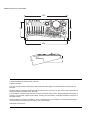
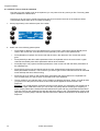
Measurements are in millimeters:
483
188
265
468
35
120
85
© 2003-2005 Martin Professional A/S, Denmark.
Printed in Denmark
This user manual has been developed by R&D International NV, Belgium on behalf of Martin Professional A/S,
Denmark.
All rights reserved. No part of this manual may be reproduced, in any form or by any means, without permission in
writing from Martin Professional A/S, Denmark.
The information contained in this document is subject to change without notice. Martin Professional AS makes no
warranty of any kind with regard to this material, including, but not limited to, the implied warranties of fitness for a
particular purpose.
Martin Profession AS shall not be liable for errors contained herein or for incidental or consequential damages in
connection with the furnishing, performance or use of this material.
P/N 35000119 Revision D
Table of contents
Chapter 1. Introduction ............................................................................................ 7
1.1 Naming conventions used in this manual................................................................................... 7
1.2 Safety ......................................................................................................................................... 8
1.2.1 Important safety instructions ............................................................................................. 8
Chapter 2. Installation ............................................................................................ 11
2.1 Hardware .................................................................................................................................. 11
2.1.1 Power connection............................................................................................................ 11
2.1.1.1 Installing a plug on the power cable.......................................................................... 11
2.1.2 DMX connection .............................................................................................................. 11
2.1.2.1 Devices...................................................................................................................... 12
2.1.2.2 DMX-in behavior ....................................................................................................... 12
2.1.3 MIDI connection .............................................................................................................. 12
2.1.4 AUDIO connection........................................................................................................... 12
2.1.5 I²C expansion .................................................................................................................. 13
2.1.6 USB link to PC................................................................................................................. 13
2.1.7 Desk light or Littlite .......................................................................................................... 13
2.2 Software ................................................................................................................................... 13
Chapter 3. The Xciter philosophy.......................................................................... 17
3.1 Show elements ......................................................................................................................... 17
3.1.1 Scene .............................................................................................................................. 17
3.1.2 Sequence ........................................................................................................................ 17
3.2 Ways of running show elements .............................................................................................. 18
3.2.1 Cue .................................................................................................................................. 18
3.2.2 Playback.......................................................................................................................... 18
3.2.3 Cue list ............................................................................................................................ 19
3.3 Tools for flexible shows ............................................................................................................ 20
3.3.1 Effect generator............................................................................................................... 20
3.3.2 Effect Macros .................................................................................................................. 20
3.3.3 Preset .............................................................................................................................. 20
3.4 Behavior of show elements ...................................................................................................... 21
3.4.1 Process priority................................................................................................................ 21
3.4.2 Dimmer channels are HTP.............................................................................................. 22
3.4.3 Transparency .................................................................................................................. 22
3.4.4 Default ............................................................................................................................. 22
3.4.5 Background scene........................................................................................................... 23
3.5 Sequence transparency across cues ....................................................................................... 23
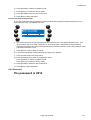
Chapter 4. Power on/off.......................................................................................... 25
4.1 Power on .................................................................................................................................. 25
4.2 Power off .................................................................................................................................. 25
Chapter 5. Joystick operation................................................................................ 27
5.1 Operation in the programmer ................................................................................................... 27
5.2 Operation in cue (run mode) .................................................................................................... 27
Chapter 6. Desk light operation............................................................................. 29
Chapter 7. Multiple shows...................................................................................... 31
7.1 Select show .............................................................................................................................. 31
7.2 Remove show........................................................................................................................... 31
Chapter 8. Setup menu........................................................................................... 33
8.1 Fixture library............................................................................................................................ 34
8.1.1 Create a new fixture definition......................................................................................... 34
8.1.2 Edit existing fixture definition ........................................................................................... 37
8.1.3 Remove fixture definition ................................................................................................. 37
8.2 Patch......................................................................................................................................... 38
8.2.1 Selecting a patch ............................................................................................................. 38
8.2.2 Copying a patch............................................................................................................... 39
8.2.3 About physical channels and logical channels ................................................................ 40
8.2.4 Fixture patch.................................................................................................................... 40
8.2.4.1 Patch fixtures............................................................................................................. 41
8.2.4.2 Edit a patched fixture number ................................................................................... 42
8.2.4.3 Clear patch data ........................................................................................................ 43
8.2.5 Dimmer patch .................................................................................................................. 43
8.2.5.1 Changing the default channel names........................................................................ 45
8.2.5.2 Soft patch .................................................................................................................. 46
8.2.5.3 Soft patch, advanced settings ................................................................................... 48
8.2.5.4 Soft patch, Limits ....................................................................................................... 50
8.2.6 DA patch .......................................................................................................................... 51
8.3 Auto-start .................................................................................................................................. 53
8.4 Access level.............................................................................................................................. 54
8.4.1 Different modes for different people ................................................................................ 54
8.4.1.1 Programmer mode..................................................................................................... 54
8.4.1.2 Operator mode .......................................................................................................... 54
8.4.1.3 Dummy mode ............................................................................................................ 54
8.4.2 Changing user modes ..................................................................................................... 54
8.4.2.1 From programmer to other ........................................................................................ 54
8.4.2.2 From other to programmer ........................................................................................ 55
8.4.3 Password ......................................................................................................................... 55
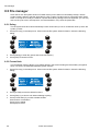
8.5 File manager............................................................................................................................. 56
8.5.1 Defrag .............................................................................................................................. 56
8.5.2 Format flash..................................................................................................................... 56
8.6 Advanced setup ........................................................................................................................ 57
8.6.1 DMX Config ..................................................................................................................... 57
8.6.2 MIDI Key association....................................................................................................... 57
8.6.3 Midi PB behavior ............................................................................................................. 58
8.7 Joystick calibration.................................................................................................................... 60
8.8 Test ........................................................................................................................................... 61
8.8.1 Key / Fader test ............................................................................................................... 61
8.8.1.1 Key test...................................................................................................................... 61
8.8.1.2 Fader and Joystick test ............................................................................................. 61
8.8.1.3 DMX test.................................................................................................................... 61
8.8.2 Other tests ....................................................................................................................... 62
Chapter 9. Program features .................................................................................. 63
9.1 Select/deselect device .............................................................................................................. 63
9.2 Select/deselect range ............................................................................................................... 63
9.3 Selection behavior .................................................................................................................... 63
9.3.1 Inclusive........................................................................................................................... 63
9.3.2 Exclusive.......................................................................................................................... 63
9.4 Device groups........................................................................................................................... 64
9.5 Fixture or Dimmer information .................................................................................................. 64
9.6 The programmer ....................................................................................................................... 64
9.6.1 Active versus transparent channels ................................................................................ 64
9.6.2 Handling logical channels................................................................................................ 65
9.6.3 Switching between DMX and percentage values............................................................ 65
9.6.4 Channel status indicators ................................................................................................ 65
9.6.5 A two layered programmer .............................................................................................. 66
9.6.6 Presets............................................................................................................................. 67
9.6.7 Undo function .................................................................................................................. 67
9.7 Scene / sequence editor ........................................................................................................... 67
9.7.1 Toggle DMX / percentage display ................................................................................... 68
9.7.2 Add, Insert and modify scenes ........................................................................................ 68
9.7.3 Modify scene and fade time............................................................................................. 69
9.7.4 Fade curve....................................................................................................................... 70
9.7.5 Preview sequence ........................................................................................................... 71
9.7.6 Lamp procedures ............................................................................................................ 71
9.7.7 Invert ............................................................................................................................... 72
9.7.8 Fan control ...................................................................................................................... 72
9.7.9 Copy/paste scene............................................................................................................ 73
9.7.9.1 Copy a scene to the clipboard................................................................................... 73
9.7.9.2 Paste a scene from the clipboard ............................................................................. 74
Chapter 10. Effect generator.................................................................................. 75
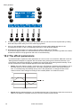
10.1 How to apply effects to logical channels ................................................................................ 75
10.2 The effect parameters ............................................................................................................ 76
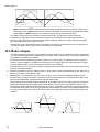
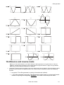
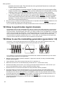
10.3 Basic shapes .......................................................................................................................... 78
10.4 Bounce and reverse mode ..................................................................................................... 79
10.5 How to synchronize logical channels ..................................................................................... 80
10.6 How to use the modulating generators (generators 1-5)........................................................ 80
10.7 How to use the BPM generators (generators 251-255) ......................................................... 81
10.8 How to use the audio feature ................................................................................................. 81
10.9 How to use the MIDI feature................................................................................................... 82
10.10 How to use the Master feature ............................................................................................. 82
10.11 How to use the BPM feature ................................................................................................ 82
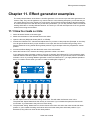
Chapter 11. Effect generator examples................................................................. 85
11.1 How to create a circle............................................................................................................. 85
11.2 How to create a dimmer chase............................................................................................... 86
11.3 How to create a color chase................................................................................................... 87
Chapter 12. Effect macros...................................................................................... 89
12.1 Create an effect macro........................................................................................................... 89
12.2 Recall an effect macro............................................................................................................ 89
12.3 Important to know ................................................................................................................... 89
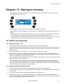
Chapter 13. Storing to memory ............................................................................. 91
13.1 Store as sequence.................................................................................................................. 91
13.1.1 Assign directly to cue .................................................................................................... 91
13.1.2 Assign directly to playback fader................................................................................... 91
13.1.3 Store to list, assign later................................................................................................ 92
13.2 Store as background scene.................................................................................................... 92
13.2.1 Assign directly to cue .................................................................................................... 92
13.2.2 Store to list, assign later................................................................................................ 92
13.3 Store as preset ....................................................................................................................... 92
13.4 Update .................................................................................................................................... 93
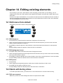
Chapter 14. Editing existing elements .................................................................. 95
14.1 Edit menu from default ........................................................................................................... 95
14.1.1 Edit Sequence ............................................................................................................... 95
14.1.2 Edit background scene.................................................................................................. 95
14.1.3 Edit preset ..................................................................................................................... 95
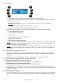
14.2 Quick edit during show ........................................................................................................... 95
14.2.1 Edit cue sequence......................................................................................................... 95
14.2.2 Edit background scene.................................................................................................. 96
14.2.3 Edit playback sequence ................................................................................................ 96
Chapter 15. Run mode features............................................................................. 97
15.1 Basic cue dialog ..................................................................................................................... 97
15.1.1 Activate – deactivate sequences................................................................................... 97
15.1.2 Sequence trigger and step mode .................................................................................. 98
15.1.2.1 Internal trigger ......................................................................................................... 98
15.1.2.2 Manual trigger ......................................................................................................... 99
15.1.2.3 None (no trigger) ..................................................................................................... 99
15.1.2.4 BPM trigger ............................................................................................................. 99
15.1.2.5 Audio trigger ............................................................................................................ 99
15.1.2.6 One-shot freeze step mode..................................................................................... 99
15.1.2.7 One-shot release step mode ................................................................................... 99
15.2 Extended cue dialog. .............................................................................................................. 99
15.2.1 Add/replace background scene................................................................................... 100
15.2.2 Add/replace sequence................................................................................................. 100
15.2.3 Remove BG scenes and/or sequences from cue........................................................ 101
15.2.4 Assign sequences to faders ........................................................................................ 101
15.2.5 Link a playback bank to a cue ..................................................................................... 102
15.2.5.1 Audio settings ........................................................................................................ 102
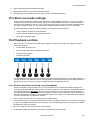
15.3 Store run mode settings........................................................................................................ 103
15.4 Playback controls.................................................................................................................. 103
15.4.1 Activate, deactivate and bump override playbacks ..................................................... 103
15.4.2 Sequence trigger and step modes .............................................................................. 104
15.4.3 Capturing the value ..................................................................................................... 104
15.4.4 Auto lock ...................................................................................................................... 104
15.5 Cue lists ................................................................................................................................ 104
15.5.1 Cue list selection ......................................................................................................... 104
15.5.2 Create a new cue list ................................................................................................... 105
15.5.3 Run cue list.................................................................................................................. 106
15.5.4 Clear cue list................................................................................................................ 106
15.5.5 Edit an existing cue list ................................................................................................ 106
Chapter 16. Direct access features...................................................................... 109
16.1 Pitch control and freeze ........................................................................................................ 109
16.2 Master, Master Flash and Black Out .................................................................................... 109
16.3 DA buttons: SMK, STRB, EXT1 and EXT2 .......................................................................... 109
Chapter 17. PC software ....................................................................................... 111
17.1 Launch the application.......................................................................................................... 111
17.2 Firmware ............................................................................................................................... 111
17.3 Library ................................................................................................................................... 112
17.3.1 Add a fixture definition ................................................................................................. 112
17.3.2 Remove a fixture definition .......................................................................................... 113
17.3.3 Export to lib.................................................................................................................. 113
17.4 Backup / Restore .................................................................................................................. 113
17.4.1 Backup......................................................................................................................... 114
17.4.2 Restore ........................................................................................................................ 114
17.5 Offline features ..................................................................................................................... 114
Chapter 18. Specifications - Xciter ...................................................................... 115
Introduction
Chapter 1. Introduction
Thank you for selecting the Martin Xciter. As well as this manual, your Xciter is supplied with a training
DVD containing videos and animations. The DVD gives an overview of your Xciter’s features and how to
use them, with clearly explained examples, so you are recommended to view it before operating the
product.
The Xciter is a hands-on lighting control tool for DJs and lighting operators. It allows instant manipulation
of the light show via easy-to-use buttons and faders for spontaneous lighting effects. Ideal for clubs, small
touring applications, and even larger mobile DJs, Xciter puts programming, playback and live
manipulation of light shows at your fingertips.
Instant pitch control, freeze, flash, blackout, master control and many other features are standard. You
can apply stunning effects to any parameter with the advanced effect generator. Functions like strobe,
smoke, etc. can be assigned to each of four programmable customizable buttons for personalized,
intuitive control. Assign effects, scenes or dimmer to any of six faders and flash buttons and access them
live during playback. Keep your finger on the pulse by increasing or decreasing the show speed by up to
5 times using the convenient pitch fader.
With Xciter you can control up to 40 fixtures. A fixture can use up to 48 DMX channels. A total of 512
channels are available in the Xciter’s DMX universe. You have access to 160 cues, each containing 4
sequences which can run simultaneously. Sequences can be triggered via an internal clock, via audio or
BPM, or manually. Up to 6 manual override scenes can be accessed during playback.
Also incorporated are 20 general-purpose buttons so that operators can select cues or fixtures directly.
Xciter also includes a joystick for manual pan/tilt control. Use fan control to create attractive spread-outs
on the pan/tilt or any channel, just at the touch of a fader. Xciter can store up to 160 presets, which can
be used on any parameter to make light shows extremely flexible in different environments. Other
features include manual override of fixture parameters and dimmer channels for direct access and
programming during the show.
Extremely easy to navigate, Xciter features easy-to-read, blue backlight LCD displays for show menu,
dialog and channel name display above the faders, as well as a jog wheel that makes it easy to scroll
through fader pages. Connect your PC directly to Xciter via the USB connection to update fixture
libraries, export/import shows, for show back up, editing, etc.
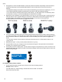
The Xciter is supplied with the following:
•
User manual
•
5 meter (16 ft.) 3-pin XLR cable
•
XLR termination plug
•
3-wire 1.5 meter (5 ft.) IEC mains cable
•
1 meter (3 ft) USB cable
•
1 desk light
•
1 training DVD that also includes PC software
1.1 Naming conventions used in this manual
The following conventions are used in this user manual:
[x]
Key with label ‘x’
{x}
Soft key with label ‘x’
Xciter user manual
7
Introduction
1.2 Safety
This product presents risks of lethal or severe injury due to electric shock. Read this manual before
powering or installing the console, follow the safety precautions listed below and observe all warnings in
this manual and printed on the console.
If you have questions about how to operate the console safely, please contact your Martin dealer or call
the Martin 24-hour service hot line at +45 70 200 201 or +1 954 858 1800.
Warnings
Always ground (earth) the console electrically.
Use only a source of AC power that complies with local building and electrical codes and has
both overload and ground-fault (earth-fault) protection.
To reduce the risk of fire or electric shock, do not expose this appliance to rain or moisture.
Refer any service operation not described in this manual to a qualified technician.
Do not modify the console or install other than genuine Martin parts.
The Xciter is not for domestic use.
Use the device only as described.
Do not operate the device if any cover is removed, damaged or deformed.
Immediately repair or replace damaged power cords.
There are no user-serviceable parts inside; refer all service to a qualified technician.
To reduce the risk of electric shock, do not remove the cover (or back).
RISK OF ELECTRIC SHOCK
DO NOT OPEN
The lightning flash with arrowhead symbol, within an equilateral triangle, is intended
to alert the user to the presence of un-insulated “dangerous voltage” within the
product’s enclosure that may be of sufficient magnitude to constitute a risk of
electric shock to persons.
The exclamation point within an equilateral triangle is intended to alert the user to
the presence of important operating and maintenance (servicing) instructions in the
literature accompanying the appliance.
1.2.1 Important safety instructions
1. Read and follow these instructions.
2. Keep these instructions.
3. Heed all warnings.
4. Do not use this appliance near water.
5. Clean only with dry cloth.
8
Xciter user manual
Introduction
6. Do not block any ventilation openings, Install in accordance with the instructions in this manual
and on the appliance.
7. Do not install this appliance near any heat sources such as radiators, heat registers, stoves, or
other apparatus (including amplifiers) that produce heat.
8. Follow all safety instructions when installing and using a grounding-type (earthed) plug.
9. Protect the power cord from being walked on or pinched particularly at plugs, sockets, and the
point where they exit from the apparatus.
10. Only use attachments/accessories specified by the manufacturer.
11. Unplug this apparatus during lightning storms or when unused for long periods of time.
12. Refer all servicing to qualified service personnel. Servicing is required when the apparatus has
been damaged in any way, if the power cable or plug is damaged, liquid has been spilled or
objects have fallen into the appliance, the appliance has been exposed to rain or moisture, does
not operate normally, or has been dropped.
Xciter user manual
9
Installation
Chapter 2. Installation
2.1 Hardware
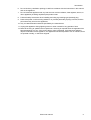
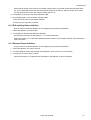
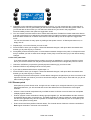
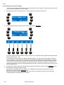
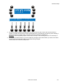
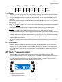
Most of the hardware connections are on the rear panel of the console.
MAINS INPUT
SERIAL DATA LINK
MIDI
AUDIO
XPANSION
2.1.1 Power connection
The Xciter does not need a mains adapter. It takes main supply directly via the IEC mains connector. The
power supply will automatically adapt to the mains voltage that is used in your area. The power supply is
quite insensitive to power drops. It can handle drops of up to 0.5 s.
The power supply is auto-ranging:
•
90VAC – 250 volts -AC
•
50Hz – 60Hz
The power rating is indicated on the serial number label that can be found on the base of the fixture.
2.1.1.1 Installing a plug on the power cable
Warning!
For protection from dangerous electric shock, the fixture must be grounded (earthed). The
AC mains supply must have overload and ground-fault protection.
The mains plug is the power disconnect device for the fixture. Note that when the mains
input plug is attached, the unit is connected to the mains power circuit. The mains input plug
must remain accessible so that the mains circuit can be disconnected from the fixture.
Important!
Verify that power cables are undamaged and rated for the current requirements of all
connected devices before use.
The fixture’s power cable requires an approved grounding-type cord cap (earthed mains plug) that fits
your local power distribution cable or outlet. This is not supplied. Consult a qualified electrician for proper
installation. Following the cord cap manufacturer’s instructions, connect the appropriate wires to ground
(earth), live, and neutral. The following table below shows some common wire identification schemes.
Function
Wire (EU)
Wire (US)
Markings
live
brown
black
L or 1
neutral
blue
white
N
ground (earth)
yellow/green
green
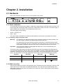
2.1.2 DMX connection
Xciter has one DMX-512 universe. The rear panel of the console has one 5-pin XLR input, one 3-pin XLR
output and one 5-pin XLR output for a DMX serial data link. The 3-pin and 5-pin outputs belong to the
same DMX universe, but they are both buffered. This means they can be used together without violating
the DMX specifications.
Xciter user manual
11
Installation
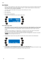
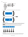
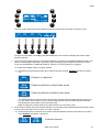
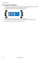
2.1.2.1 Devices
out
in
out
in
out
in
out
DMX terminator
3-pin or 5-pin out
in
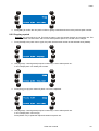
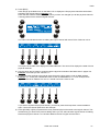
2.1.2.2 DMX-in behavior
The DMX input is HTP-mixed (HTP=Highest Takes Precedence) with the DMX output. You can use the
DMX input to hook up a generic lighting desk to the Xciter. This way you can control the generic lights or
dimmers from the Xciter and the generic lighting desk at the same time on the same universe. HTP on
this connection means that the desk with the highest value on the same DMX channel will take control on
that channel.
Fixtures
Dimmers
3-pin out
5-pin in
5-pin out
Generic (dimmer)
lighting desk
2.1.3 MIDI connection
If you have a MIDI device to control your shows, you can connect it to the MIDI IN socket. You can also
patch through via MIDI THRU.
Xciter accepts the following MIDI commands:
•
Note ON and note OFF to activate playbacks and cues.
•
Note ON and note OFF to remotely press and release any key on the front panel except the power key.
If you press a cue or bump button with a MIDI command assigned to them, Xciter also sends that
command through MIDI OUT. This way you can also use MIDI for master/slave connection of multiple
consoles without the need for DMX splitters. Remember however that Xciter only accepts the MIDI
commands noted above, which are only useful for on/off actions, not linear control of faders.
2.1.4 AUDIO connection
The desk also has audio triggering capabilities. There is an internal microphone if no direct audio feed is
available. We recommend a direct audio line to get the best results out of the audio trigger. You can plug
audio into the 6.3mm (0.25 inch) mono jack. When using the line-in, the internal microphone is switched
off.
Use standard audio signals like the pre-amp output from your audio mixer to get the best results. If you
want to have even more control over the audio trigger, you can place an equalizer between the audio
source and the console.
Warning: DO NOT connect an amplified output like the speaker output from an amplifier, to the AUDIO
connection, as it may damage the console.
12
Xciter user manual
Installation
2.1.5 I²C expansion
Use this connector to attach accessories to the console.
As you can see, the I²C expansion port is the same as MIDI. Connecting MIDI to this port will not damage
the console.
Warning: Martin accessories only. DO NOT connect other devices, as this may damage the console.
2.1.6 USB link to PC
You need a USB-A to USB-B cable to connect your Xciter to a desktop or laptop. Use the USB link to
upload new firmware, download and upload fixture definitions and do backup/restore of shows. Later in
this manual, we will explain how to use the PC applications that come with Xciter.
2.1.7 Desk light or Littlite
The USB-A connector on the front panel must only be used to supply power to a desk light.
Attention: you can draw a maximum of 315 mA from this port. Check the specification of your desk light
before using it.
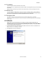
2.2 Software
Before Xciter can communicate with your PC or laptop, you need to install the USB drivers and
applications on your PC. You can find them on the CD supplied with the Xciter. We recommend that you
download the latest applications from the Martin website at http://www.martin.com. They may contain
newer firmware and new fixture definitions.
1. If you have a previous version of the PC software installed, make sure the Xciter is not attached to the
USB port while you are installing PC software.
2. Run setup.exe to launch the install wizard.
3. Click next in the intro screen.
Xciter user manual
13
Installation
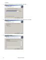
4. Specify an install directory or use the one suggested. Click next.
5. Check whether or not you would like setup to create a desktop icon. Click next.
6. Click install to confirm.
14
Xciter user manual
Installation
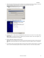
7. When setup has finished copying all the necessary files, it will display the following message. If you had a
previous installation, make sure there is no Xciter connected to the PC at this point.
8. Finally, press Finish to exit the setup wizard.
9. Power the Xciter on. Wait until it has completed booting and shows the intro screen. This normally takes a
few seconds.
Note: If a previous upgrade has failed, the displays may remain dark. However, even if this happens, you
should still be able to perform a new upgrade.
10. Use the USB cable to attach the Xciter to the PC.
Warning: Only use the USB-B connector (center-top of the front panel) on the Xciter to connect to the PC.
The USB-A connector (top-right corner of the front panel) only serves to supply 5V power to a USB desk
light.
11. The operating system will automatically detect the Xciter and the hardware wizard will appear. If the wizard
asks to connect to Windows® Update to search for software, select ‘No, not this time’ and press next.
Xciter user manual
15
Installation
12. The wizard will install the software automatically by default. Keep this option and press next.
If the PC software was installed successfully, the wizard will install and register all the necessary files.
Press finish to exit the wizard.
16
Xciter user manual
The Xciter philosophy
Chapter 3. The Xciter philosophy
This chapter will give you an overview of the product and the basic concepts you need to understand to get
the best out of it. We strongly recommend you to view the DVD supplied with Xciter. The DVD contains
training sequences that give a clear overview of the product and how to use it.
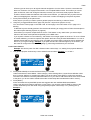
3.1 Show elements
The two elements most basic elements in shows are scenes and sequences.
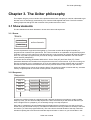
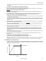
3.1.1 Scene
Scene
scene time
active channels
fade time
A scene represents a single look of the lighting rig. The scene contains all the logical channels you
programmed to create the look (see section 8.2.3 of this manual for an explanation of logical and physical
channels). Later on in this manual you will discover that it is not necessary to program all channels inside a
look. You only need to program those you want to change, called the active channels. The rest of them
remain inactive (transparent).
The scene has two timing parameters attached to it: Scene Time (ST) and Fade Time (FT). These
parameters determine the transition from the previous scene to the current scene. If you are not using cue
lists, the scene time is of no consequence. So if you are calling up the scene manually with a cue button,
the fade time will determine the transition rate from the previous scene to the scene you just selected.
Xciter can hold as many scenes as its memory allows. The maximum number of scenes will vary, because
memory usage depends on the scene content (number of active channels).
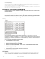
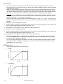
3.1.2 Sequence
Sequence
step 1
scene time
fade time
step 2
scene time
fade time
step 3
scene time
fade time
step 4
scene time
fade time
A sequence consists of steps in a sequential order. Although sequences are meant to contain multiple
steps, up to 99, you can store one-step sequences. Later in this manual you will discover that when you
store a single scene to a playback, you are actually storing a one-step sequence.
Each step in a sequence has timing parameters that determine the transition from one step to the next:
Scene Time (ST) and Fade Time (FT). The fade time determines how long it takes for the step to reach its
end values (i.e. reach the programmed look). The scene time is the total duration of the step, fade time
included. Adjusting the scene time will make the sequence faster or slower. As you will see later in this
Xciter user manual
17
The Xciter philosophy
manual, you can adjust the timing parameters globally, meaning each step gets the same parameters, or
locally, meaning you can set a different timing for each step.
Xciter can hold as many sequences as its memory allows, depending on the sequence content (number of
steps and number of active channels per step).
3.2 Ways of running show elements
Scenes and sequences are very straightforward and are quite easy to create using the console’s intuitive
programming features.
•
A scene contains a single look
•
A sequence can contain up to 99 looks called steps
In this section we will give you a taste of how Xciter’s many playback features mold these basic elements
into powerful and versatile constructs. There are many different ways to create and playback a show. You
will eventually have to decide how you are going to playback the content you created.
3.2.1 Cue
Cue
highest priority
Sequence A
trigger
run mode
Sequence B
trigger
run mode
Sequence C
trigger
run mode
Sequence D
trigger
run mode
Background scene
lowest priority
The cue serves as a container to combine several show elements in order to launch and run them
simultaneously (in parallel). Xciter allows you to combine one scene called the background scene and four
sequences into a cue. With 8 page buttons and 20 number buttons, you can launch 160 cues directly from
the front panel.
The cue comes with a wide variety of playback features:
•
Activate/deactivate background scene.
•
Activate/deactivate each sequence separately.
•
Sequence trigger: internal, manual, audio, BPM.
•
Sequence run mode: forward, backward, bounce, random, one-shot freeze and one-shot release.
•
Comprehensive audio settings.
•
Quick link to playback bank.
•
Assign background scenes, playback scenes and sequences live
These features are described below.
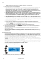
3.2.2 Playback
With the cue, you can launch and run up to 5 show elements simultaneously using the right side of the
console. You already have a great deal of control over the show with the four sequences that you can
18
Xciter user manual
The Xciter philosophy
start/stop individually in each cue. However, many people will find the degree of control on the left side of
the console even more interesting.
Xciter can contain up to 160 banks of 6 playback faders. Of course only one bank (6 faders) is visible at
any one time, as illustrated below. With these controls, you can launch another 6 sequences on top of
whatever is running in the cue. The sequences you launch with the playback faders have a higher priority
than the content running in the cue, meaning common channels will be overridden, except for dimmer
channels which are HTP (Highest Takes Precedence). This is covered later in this chapter under process
priority and cue (run) mode.
Visible bank
3.2.3 Cue list
Cue List
Cue
Step 1
Step options
Cue
Step 2
Step options
Cue
Step 99
Step options
The purpose of a cue list is to make playback of a show automatic or semi-automatic depending on
whether there is an operator or not. Cue lists are ideal when somebody with little knowledge about lighting
operates the console.
A cue list can contain up to 99 steps. Each step in the cue list refers to an existing cue that you would call
manually when operating the console yourself. They are similar to sequences but at a much higher level.
That is why we also call them automated shows.
The step options determine the behavior of the show.
•
WAIT
•
FOLLOW
•
GOTO
•
LOOP
•
LAMP_ON
•
LAMP_RESET
•
LAMP_OFF
•
GO
Later in this manual we will look more closely at cue lists and step options
Xciter user manual
19
The Xciter philosophy
3.3 Tools for flexible shows
3.3.1 Effect generator
Use Xciter’s powerful effect generator to add dynamics to your background scenes and sequences. There
are 255 effect generators that you can use on any logical channel. That means you are not limited to
pan/tilt movement with effects. Later in this manual you will learn how helpful the effect generator can be
when creating dimmer chases, color wheel chases, CMY effects, etc.
In addition, Xciter´s powerful fading engine also fades on the swing, speed and delay of effects if you want
it to. Example: The fixtures pan/tilt from a small circle to a big circle back and forth in a two-step sequence.
If you put the effect parameters on fade, the fixtures will spiral in and out. If you put the parameters in snap
the effects will come on instantly.
Some key features of the effect generator:
•
Variable speed and swing.
•
Variable delay across channels.
•
Variable delay across fixtures.
•
Multiple shapes like sine, square, saw tooth, etc.
•
Bounce, reverse, reverse + bounce
•
Generator modulation
•
Audio modulation
•
BPM adaptive generators
The effect generator and its parameters will be discussed in more detail in this manual when we discuss
advanced programming.
3.3.2 Effect Macros
The previous section gave a brief introduction to the effect generator. It also gave a summary of
parameters that make the effect generator an extremely versatile tool, but a comparatively slow one if you
only want to create simple effects or need to have a more complex effect quickly. The effect macros allow
you to store effect parameters in a kind of effect preset, so you can recall it later.
Example: You have created an effect in a background scene before and want to reuse it. Without effect
macros, you would either have to recall the scene you made before and start building from there, or you
would have to remember all the parameters to recreate the effect from scratch.
Note that the effect macros do not store fixture information. This means that the delay across fixtures is not
stored. When you apply the effect macro in a scene, Xciter applies all effects that you stored before but
without delaying them across the fixtures you selected. You need to set the fixture delay yourself if you
want one. This point is covered later in this manual.
3.3.3 Preset
Presets are very useful when you change the rig (fixture setup) a lot. Presets are logical channels or
complete looks that you preprogram. In the scenes and sequences, you reference to those presets. When
you modify something in your rig (Example: move a fixture) you don’t have to modify or reprogram all your
scenes and sequences. You only need to modify the preset. All scenes where you have used the preset,
will be modified as well. Although presets require some experience, they are worth checking out because
they can save you a lot trouble when you modify the rig. Xciter can store up to 160 presets, depending on
the preset content.
Example: You move around with a band but the podium has almost the same setup every time. When you
use the presets in your show, you only need to make small changes to those presets to make your show
perfect again. They will save you time positioning the fixtures in the rig or reprogramming the show.
20
Xciter user manual
The Xciter philosophy
3.4 Behavior of show elements
We call a running scene or sequence a process. You may not see it, but while you are programming or
creating a show, Xciter is running several processes in parallel (background scenes, sequences, playback
faders, programmer, direct access buttons, lamp procedures, etc.).
The following sections cover the behavior of show elements inside a show.
3.4.1 Process priority
Very often these processes have common channels, which means that they try to apply their own value to
the same destination, i.e. the same DMX address. Xciter has the following scheme to prioritize these
processes. This way you will get the same behavior every time you run the show and – most importantly –
you can predict that behavior when programming it.
highest priority
8
system functions
7
direct access
6
programmer, active
5
programmer, inactive
temporary active channels in editor, not stored
4
override playbacks
sequences, activated with faders, during show
2
sequences
1
background scene
0
default
Lamp on, Lamp off, Lamp reset
smoke, strobe, extra1, extra2
active channels in scene editor, stored
sequences A, B, C, D in the cue
background scene in the cue
default scene, when no other processes are active
lowest priority
Example 1: You have programmed some PAN and TILT values and dimmer open for a certain fixture in
the background scene. While this background scene is active in the show, you select the same fixture and
move the joystick. By doing this you put PAN and TILT values in the programmer on layers 5 and 6. These
layers have a higher priority (see priority table), thus you override the PAN and TILT values of the
background scene. This action is also called manual fixture override.
DIM
PAN
TILT
COLW
---
80
100
---
Programmer active
---
---
---
---
Programmer inactive
255
128
24
---
Background Scene
255
80
100
---
Result on DMX
Xciter user manual
21
The Xciter philosophy
Example 2: You have programmed a color value in the background scene. During the show you can
override this color with a playback fader because it will be running at a higher priority.
DIM
PAN
TILT
COLW
---
---
---
60
Playback fader at full
255
128
24
45
Background Scene
255
128
24
60
Result on DMX
3.4.2 Dimmer channels are HTP
Dimmer channels include fixture channels with the label DIM and all channels of dimmer units. They do not
follow the priority scheme described above. Instead, they are HTP (Highest Takes Precedence). This
means that the highest value is applied to the DMX output, no matter what the priority of the process is.
Example 1: You set the dimmer of a certain fixture to fully open in the background scene. You will find that
you cannot close it with a playback fader. You can only do it with another background scene.
3.4.3 Transparency
When you program a scene or sequence on the Xciter, you are only storing the logical channels you used
to program the look, i.e. the so-called active channels. When you run that scene or sequence in the show,
the process can only apply those same channels to the output, unless a higher process uses the same
channels (see Process priority). The other channels remain transparent; the process is not using them.
Transparency has an important consequence: The transparent channels of a process will not override
channels of a lower priority process.
Example: The background scene of cue 1 puts some fixtures in a certain position with open dimmers.
Sequence B from cue 1 runs a color chase on the same fixtures but the rest of its channels are
transparent. The result is on the DMX output is the position and dimmer values from the background scene
and the color chase because the sequence only overrides the color channels.
DIM
PAN
TILT
COLW
---
---
---
---
Sequence A
---
---
---
120
Sequence B
---
---
---
---
Sequence C
---
---
---
---
Sequence D
255
128
128
---
Background Scene
255
128
128
120
Result on DMX
3.4.4 Default
The Default layer is always running. When a certain logical channel is transparent in all processes,
meaning no other process is using the channel, the value of the default layer is output for that channel.
This value is the library default for fixture units and the low limits for dimmer units. Later in this manual you
22
Xciter user manual
The Xciter philosophy
will learn about programming from default. You will see that all transparent channels in the programmer will
get values from the default layer.
When the console is booting, the system default (all 0) is output. After that the default layer takes over.
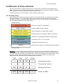
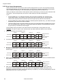
3.4.5 Background scene
In the run mode chapter you will learn how to playback cues. When running BG (background) scenes
inside cues, you will discover that the scenes do not replace one another. New channels are added to the
current look and only existing ones are replaced.
Default layer
CUE 1: BG Scene
CUE 2: BG Scene
CUE 3: BG Scene
CUE 4: BG Scene
DIM
PAN
TILT
COLW
0
128
128
0
0
128
128
0
---
128
110
---
0
128
110
0
255
---
---
---
255
128
110
0
---
---
---
35
255
128
110
35
---
---
---
68
255
128
110
68
DMX
Result on DMX
Result on DMX
Result on DMX
Result on DMX
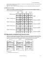
3.5 Sequence transparency across cues
When you are putting sequences behind cue buttons you have to keep in mind that Xciter has sequence
transparency. When there is no sequence in the next cue to take over the sequence in the current cue, the
sequence from the current cue will keep running. However, you can still deactivate it. In the previous
section you have already learned that background scenes cumulate looks as you launch them.
Cue 1
Cue 2
running processes
A: SEQ1
A:
A: SEQ1
B:
B: SEQ2
B: SEQ2
C:
C:
C:
D: SEQ3
D: SEQ4
D: SEQ4
BG1
BG2
BG1 + BG2
Launch cue1:
•
SEQ1 starts running on layer A.
Xciter user manual
23
The Xciter philosophy
•
SEQ3 starts running on layer D.
•
BG1 starts running on the background scene level.
Launch cue2:
•
There is no sequence in layer A; SEQ1 from cue1 will keep running.
•
SEQ2 starts running on layer B.
•
SEQ4 replaces SEQ3 from cue1 because they are both on layer D.
•
BG2 is combined with BG1.
The following processes are running as a result of cue1 followed by cue2:
•
SEQ1 is running on layer A.
•
SEQ2 is running on layer B.
•
SEQ4 is running on layer D.
•
The combined looks of BG1 and BG2 are running.
Because of this sequence transparency, you have to remain consistent when assigning sequences to cues.
Observe the following example:
Cue 1
Cue 2
running processes
A: Blue
A:
A: Blue
B:
B: Green
B: Green
C:
C:
C:
D: PT wall
D: PT centre
D: PT centre
DIM open
DIM effect
DIM effect
Cue1: dimmer open, blue color and PT (pan/tilt) on the wall.
Cue2: dimmer with effect, green color and pan/tilt on the centre of the dance floor.
Cue 1 followed by Cue2 results in the following look:
•
The dimmer effect is there because it has been placed in the background scene in both cues.
•
The PT centre is there because the PAN and TILT information has been put in sequence D in both
cues. There is no sequence running at a higher level that can override the PAN and TILT at this
point.
•
The color poses a problem. It will not go green upon pressing cue 2 because the blue sequence on
layer A keeps running. The green color will only become visible the moment you deactivate
sequence A with the blue color. This because layer A has a higher priority.
Hint 1: Remember dimmer channels are HTP. The HTP principle won’t bother you if you always put the
dimmer information on the same priority level as shown in the example above.
Hint 2: To avoid difficulties with sequence transparency, order the sequences as follows:
24
•
A: Intensity (dimmer, shutter).
•
B: Color (color wheel, CMY, RGB).
Xciter user manual
The Xciter philosophy
•
C: Beam (Gobo wheel, animation wheel, iris, zoom, prism, frost)
•
D: Focus (Pan, Tilt)
Chapter 4. Power on/off
4.1 Power on
Make sure the Xciter is connected to mains power and press the power button in the top left corner of the
console.
Xciter scans the internal file system and restores the database.
The intro screens appear on the main and fader LCD displays.
4.2 Power off
Hold the power button pressed for at least 2 seconds – until the displays and LED’s go dark – to power off.
Xciter user manual
25
Joystick operation
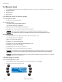
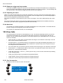
Chapter 5. Joystick operation
If you are using the Xciter for the first time, you may need to calibrate the joystick. See joystick calibration
in the setup menu.
1. Press {Joystick} in the setup menu.
2. Move the joystick in a circle around the limits of its travel a couple of times.
3. Press [STORE] to store the calibration.
4. Press any button to continue. Xciter returns to the setup menu.
5.1 Operation in the programmer
Xciter’s self-centering joystick always works in relative mode.
When you push the joystick in a certain direction, the beam will move in that direction and the further you
push the joystick from the centre, the faster the beam will move.
Sometimes the individual fixtures of a group are positioned differently so the beams all move in different
directions when you manipulate the joystick. You can solve this in the patch with PAN-inverse, TILTinverse and PT-swap.
Press [PAN] and [TILT] to activate / deactivate the joystick in the programmer. You can also use these
buttons to lock the pan or tilt action of the joystick.
Use [C/F] to toggle between coarse and fine movement.
The joystick also has a built-in button. Press the joystick down to bring the fixtures back to their home
position (library defaults for PAN and TILT).
5.2 Operation in cue (run mode)
The [C/F] button becomes the BPM record button in cue (run mode). Pressing this button at a certain
tempo will cause the sequences in BPM mode to follow this tempo.
The [TILT] button becomes the step button in cue (run mode). Pressing this button will cause sequences in
manual mode to advance one step.
Xciter user manual
27
Desk light operation
Chapter 6. Desk light operation
If you have a desk light installed, you can adjust its intensity by holding down [SHIFT] while you turn the top
right jog wheel.
Xciter user manual
29
Multiple shows
Chapter 7. Multiple shows
In theory, Xciter can store up to 160 shows. The number of shows Xciter can actually store depends on the
content of each show. So in fact it depends on how much you program in each show. When you use the
Xciter for the first time, it loads show 101 after startup. You can see the current show number in the intro
screen. The second number next to the show number indicates the current patch that is attached to the
show. Later you will see that you can attach another patch to the current show.
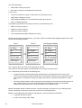
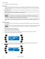
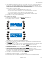
7.1 Select show
1. Press {Show} in the intro screen.
2. Select a show by using page keys 1-8 for the first digit and general-purpose keys 1-20 for the second and
third digits in the show’s number. Example: 102
3. Press [ENT] to confirm or [ESC] if you wish to cancel and return to the original show.
4. Upon confirmation, Xciter loads the selected show and returns to the intro screen.
If you have not selected another patch for the show before, Xciter uses the same patch number as the show
number that you have just selected.
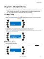
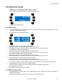
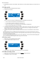
7.2 Remove show
1. Press {Show} in the intro screen.
2. Use page keys 1-8 and general-purpose keys 1-20 to select the show you wish to delete. Example: 102.
Xciter user manual
31
Multiple shows
3. Press [CLEAR].
4. Press {Yes} to confirm, {No} to cancel.
5. Press [ESC] to return to the intro screen.
32
Xciter user manual
Setup menu
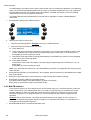
Chapter 8. Setup menu
The setup menu is only accessible from the start-up screen. If the Xciter is not in programmer mode, it will
ask for the password (X512) to go to programmer mode. You have to provide this password to enter the
setup menu.
Press {Setup} in the intro screens
Xciter user manual
33
Fixture library
8.1 Fixture library
The Xciter is delivered with most Martin fixtures already in its library. On top of that, the PC application
holds a couple of hundred more fixtures from other brands. Later in this manual you will learn how to
transfer them from the PC library into the Xciter library. The console needs a fixture library to access the
channel settings of the fixtures (dimmer, shutter, color wheels, gobo wheels, effect wheels, pan, tilt, etc.).
You can also add, remove and edit fixture definitions. If you can find your fixtures in this library, there is no
need for you to create your own profiles. You can proceed straight to the patch. You can still come back to
the library editor to modify the fixture profiles for your own needs. Example: To put a default value on the
focus.
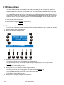
1. Press {Library} in the setup menu.
2. Select a fixture category (Example: moving mirror).
3. Select a manufacturer (Example: Martin).
8.1.1 Create a new fixture definition
First you have to select the category and manufacturer subfolders where you want to create your definition.
1. Press [LOAD] to add a fixture definition.
2. Xciter calls the fixture definition editor.
3. Press {Fixture type name} to name the fixture definition.
Use the arrow keys or the top right jog wheel to move the cursor.
Use general-purpose keys 1-10 to input numbers and general-purpose keys 11-19 to input letters
(Example: test).
Press [ENT] to confirm, [ESC] to cancel.
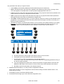
4. Press {Channel cnt:} to adjust the number of logical channels.
Use the arrow keys or the top right jog wheel to modify the value (Example: 8).
Use [CLEAR] and general-purpose keys 1-10 to input a new value.
Press [ENT] to confirm, [ESC] to cancel.
5. Press {Channel Config} to configure logical channels.
34
Xciter user manual
Fixture library
The parameters that make up a logical channel:
•
Under Label you find all the predefined channel names that you can choose from.
•
Deflt or the default value is the value that is applied to the default layer when Xciter is running a show.
This value appears on the DMX when no other process is applying another value to it.
•
Lolim or low limit is the lowest value that Xciter will output on any physical channel that is patched to this
logical channel, even when you programmed a lower value.
•
Hilim or high limit is the highest value that Xciter will output on any physical channel that is patched to
this logical channel, even when you programmed a higher value.
•
With Fa/Sn or default fade/snap mode, you set the mode the channel is in when you first activate it in the
programmer. If you put this in the most commonly used mode for that type of channel, it will save you a
little time during programming.
•
With Invrs or inverse, you tell the Xciter whether or not to invert the value before sending it out on DMX.
Example: Your fixture´s dimmer opens at 0 and closes at 255 instead of the other way round. If you
invert the channel, it will be inverted twice which results in normal control over the channel.
a. Use the arrow keys or the top right scroll wheel to select a control channel.
b. Press [EDIT] to set the parameters of the selected channel.
c.
Use the faders to modify the parameters of the selected channel.
To fine-tune a value, you can hold the bump button under the corresponding parameter while you
turn the top centre jog wheel.
d. If you are modifying the channel name, use the bump button to toggle between coarse and fine
(MSB and LSB). Upper case indicates a coarse channel; lower case indicates a fine channel.
e. [STORE] to store the parameters of the selected channel.
6. Repeat the previous steps (a – e) until you have configured all channels.
Xciter checks whether you have configured all channels before exiting the fixture definition editor. If not,
Xciter asks you to retry.
7. Press [ESC] to return to the fixture definition editor.
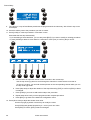
8. Press {Advanced Config} to go to the advanced configuration menu.
Xciter user manual
35
Fixture library
9. The Lamp on, Lamp off and Reset procedures are programmed in the same way. We will use Lamp on as
an example.
10. Press the softkey next to the procedure you wish to create.
11. Press [LOAD] to create a procedure in case there is none.
Xciter adds the first step automatically.
If you are editing a fixture definition, you can also press [EDIT] if you want to modify an existing procedure
or press [CLEAR] to delete it. Xciter asks for confirmation. Press {Yes} to confirm, {No} to cancel.
a. Use the faders to adjust the internal control channels in the current step.
Use the top center jog wheel to scroll through the channels in case there are more than 6.
To fine-tune a value, you can hold the bump button of the corresponding channel while you turn
the top center jog wheel.
b. Press {Step time} to adjust the duration of the step followed by [ENT] to confirm or [ESC] to leave
unchanged.
c.
Press [LOAD] if you want to add another step to the procedure.
d. Repeat steps 9a-9c until you have programmed the complete procedure.
e. Press [ESC] to go back to the advanced configuration menu.
12. Press {Shut close} to adjust the shutter close value.
Use the top right jog wheel or arrow keys to modify the value.
Use [CLEAR] and general-purpose keys 1-10 to input a new value.
Press [ENT] to confirm, [ESC] to leave unchanged.
36
Xciter user manual
Fixture library
Xciter puts the shutter close value on the shutter channel when you pull the master intensity fader below
3%. This is especially useful when the fixture has a shutter but no dimmer. With the shutter close value,
you can still black it out when the master intensity goes to 0%.
13. Press [ESC] to go back to the fixture definition editor.
14. Press [ESC] again to exit the fixture definition editor.
Xciter will ask to store the new fixture definition.
Press {Yes} to accept, {No} to decline.
8.1.2 Edit existing fixture definition
First you have to locate the definition in the category and manufacturer subfolders.
1. Select the definition you wish to edit.
2. Press [EDIT] to edit the selected fixture definition.
Use the same procedure as described in 8.1.1 to edit the definition.
Xciter will not allow you to edit critical parameters (like channel cnt) of a fixture definition if this definition is
used in the patch.
8.1.3 Remove fixture definition
First you have to locate the definition in the category and manufacturer subfolders.
1. Select the definition you wish to remove.
2. Press [CLEAR] to remove the selected fixture definition. Xciter will ask for a confirmation.
3. Press {Yes} to confirm, {No} to cancel.
Xciter will not allow you to delete a fixture definition if this definition is used in the patch.
Xciter user manual
37
Patch
8.2 Patch
Before you start programming, Xciter needs to know which devices are connected to its DMX universe and
how it will control them. This is where the patch comes in. To patch a device means to connect it to the
Xciter controls, so you are able to manipulate it.
The Xciter controls are divided into three groups, which enable you to control:
•
Up to 40 fixtures.
•
Up to 20 dimmers.
•
Up to 4 direct access devices.
Press {Patch} in the setup menu to access the patch menu.
8.2.1 Selecting a patch
Since Xciter can store up to 160 patches, each show can have its own patch assigned to it. Xciter is set up
with one patch per show by default. This means that, when you select another patch number, Xciter uses
the patch for the current show. The default patch number is the same as the show number in the intro
screen.
If you use the same lighting rig in multiple shows, you will want to use the same patch in those shows.
Xciter lets you reuse one patch in multiple shows by reassigning it to those shows.
Example: Show 102 is the current show. By default it has patch 102 assigned to it. We wish to use patch
101 on that show (same patch as show 101).
1. Press {Patch#} in the patch menu. By default, the patch has the same number as the selected show.
2. Use page keys 1-8 and general-purpose number keys 1-20 to select patch 101.
In our example, patch 101 already has content. If a patch has content, Xciter will give you the option to copy
the content of the current patch into another patch. We will explain this later.
38
Xciter user manual
Patch
3. Press [ENT] to confirm the new patch number or [ESC] to decline and return to the previous patch number.
8.2.2 Copying a patch
Example: Our current show is 102. This time we want to copy the content of patch 101 into patch 102. This
function is useful if we want show 102 to use a similar patch to patch 101, but with minor changes.
1. Press {Patch#} in the patch menu. Again, the patch has the same number as the selected show (default).
2. Use page keys 1-8 and general-purpose number keys 1-20 to select patch 101.
In our example patch 101 already has content.
3. Press {Copy} to copy the content of patch 101 into the clipboard.
4. Use page keys 1-8 and general-purpose number keys 1-20 to select patch 102.
In our example patch 102 is empty.
Press {Paste 1/01} to paste the clipboard content into patch 102.
Xciter user manual
39
Patch
5. Press [ENT] to confirm and return to the patch menu. If you press [ESC] at this point, the patch is copied but
not reloaded. The new patch still shows as empty until you exit and re-enter the patch menu.
8.2.3 About physical channels and logical channels
You will see the terms ‘physical channel’ and ‘logical channel’ a lot in this manual. You need to know what
they mean to better understand this manual.
Physical channels or DMX channels are the channels as they occur on the DMX output. They start at
channel 1 and end at channel 512. Channel 0 is reserved for special purposes which are not discussed in
this manual.
Logical channels are the channels you use to control a particular fixture (or group of fixtures if they share
the same DMX address).
For reasons of convenience, when this manual mentions channels, it generally refers to the logical
channels you use to control a selected device. If there is a danger of confusion, this manual specifies which
type of channel is referred to.
Example: CH001 (dimmer channel 1) is on channel 480.
Example: Use fader 1 to set the value of CH001 to 128.
In the above examples, the fixture’s logical channel CH001 is patched to physical channel 480 on the
controller.
8.2.4 Fixture patch
Each fixture type has its own set of logical channels, which are described in a fixture definition.
internal library
DMX channels
Martin MX-4
22
23
24
25
26
27
28
SHUT
COLW1
GOBW1
PAN
TILT
PTSPD
CGSPD
fixture type
logical
channels
A fixture on a DMX link occupies its logical channel 1 (the DMX address or start address you specify in the
patch) plus the channels immediately above this channel. The space a fixture occupies in the DMX
universe depends on the number of logical channels it uses.
40
Xciter user manual
Patch
A fixture type can have up to 48 logical channels assigned to it on the Xciter. However, remember that
there is a maximum of 512 physical channels in one complete DMX universe. This means you cannot
patch 40 devices, each with 48 logical channels, because you would need 1920 physical channels.
Thanks to Xciter’s interactive features and intuitive user interface, you will find it easy to patch fixtures
without overlapping their channels. In fact, Xciter does not allow overlapping in the patch anywhere.
1. Press {Fixture Patch} in the patch menu.
Xciter informs you that you need to press a general-purpose number key to select a fixture.
2. Use [FIXT] to toggle between fixture page one (fixtures 1-20) and two (fixtures 21-40).
You can see the current page on the fader LCD. In fixture page 1 the FIXT button is lit, in page 2 it is
blinking.
Lit Number keys are already patched. We recommend selecting an empty patch to follow the examples in
this manual (see Selecting a patch on page 38).
Xciter allows you to patch multiple fixtures at once. This feature is very useful when you want multiple
fixtures of the same model patched sequentially on the DMX chain.
If you unpatch a fixture from a number key, that fixture will no longer appear in the show. To move a fixture
to another address, you need to unpatch and repatch the fixture using another DMX address. You can readdress fixtures without corrupting the show, provided you use the same number key and re-address the
device on your rig accordingly. Example: If you patch a fixture two channels higher up in the Xciter, you
also need to configure the fixture in the lighting rig, advancing its address by two channels.
8.2.4.1 Patch fixtures
Example: We wish to patch four MX-4 fixtures under number keys 1-4, starting from physical address 1.
1. Use general-purpose number keys 1-20 to select fixture numbers. Example: 1, 2, 3 and 4.
2. Press {Select Model} to browse the fixture library for a model.
Under manufacturer, select’Martin’. Under category, select ‘Moving Mirror’ Locate fixture definition ‘MX4
6CH’ in the list. Select it by pressing the softkey next to the name. Press [ENT] to confirm the selection.
The fader LCD shows the currently selected model now. If you wish to add more fixtures of the same model
to the patch, you do not need to reselect the model. Xciter keeps the last selected model in memory.
3. Press {DMX:}.
Xciter calculates the required DMX space and suggests the next available DMX start address.
Use the top right scroll wheel to adjust the current value. You can also press [CLEAR] to clear out the
current value and input a new value using the general-purpose number keys 1-10 (10 being the 0).
Example: 1
Xciter user manual
41
Patch
4. Press [ENT] to confirm the DMX address. Xciter then patches the fixtures sequentially under the selected
number keys starting from the specified DMX address. Xciter will also take into account the order of
selection.
The Dipswitch settings on the fader LCD are useful for addressing your fixtures in the lighting rig. You can
even rotate the Dipswitch display by pressing the bump button under the Dipswitch settings.
If you cannot find the necessary fixture type in Xciter’s library, you will either have to use the library editor
to create one on the fly, or use the PC application to download one via USB.
5. Depending on the orientation of the patched fixture on the rig, you can inverse the pan, inverse the tilt and
swap pan and tilt. This is a global setting for the fixture to make pan/tilt control with the joystick easier. As
you will see later in this manual, you can still invert channels for your show in the programmer.
Press the softkeys next to the options to toggle them on/off.
TILT inverse
PAN inverse
PAN/TILT swap
6. You can choose to exclude a device from master and/or blackout. Exclude from master means the dimmer
or shutter of the fixture is not affected by the master fader. Exclude from blackout means the blackout button
does not affect the dimmer or shutter of the fixture. Press the softkey next to the options to toggle them
on/off.
You can see the status of every option by looking at the square next to it. A filled square means on, an
empty one off.
7. Repeat these steps 1-5 until you have patched all fixtures on your rig.
8. Press STORE to store your changes. If Xciter has detected changes, it will report that it has stored them
and asks you to press any key to continue.
9. Press [ESC] to leave the fixture patch. If Xciter detects changes to the patch that you have not stored, it will
report this and asks you whether you wish to store those changes. Press {Yes} to store and exit, {no} to exit
without storing changes.
8.2.4.2 Edit a patched fixture number
1. Use the general-purpose number keys to select a fixture that is already patched.
Example: fixture number 4.
The LED under key 4 starts blinking to indicate that fixture number 4 is selected.
Xciter shows the patch data.
42
Xciter user manual
Patch
2. Depending on the orientation of the patched fixture on the rig, you can inverse the pan, inverse the tilt or
swap pan and tilt. This is a global setting for the fixture to make pan/tilt control with the joystick easier. As
you will see later in this manual, you can still invert channels for your show in the programmer.
Press the softkeys next to the options to toggle them on/off.
3. You can choose to exclude a device from master and/or blackout. Exclude from master means the dimmer
or shutter of the fixture is not affected by the master fader. Exclude from blackout means the blackout button
does not affect the dimmer or shutter of the fixture. Press the softkey next to the options to toggle them
on/off.
You can see the status of every option by looking at the square next to it. A filled square means on, an
empty one off.
4. Repeat steps 1-3 on other fixtures you want to edit.
5. Press STORE to store your changes. If Xciter has detected changes, it will report that it has stored them
and ask you to press any key to continue.
6. Press [ESC] to leave the fixture patch. If Xciter detects unstored changes to the patch, it will report this and
ask you whether you wish to store those changes. Press {Yes} to store and exit, {no} to exit without storing
changes.
8.2.4.3 Clear patch data
If you want to assign a different fixture model to a unit key or readdress it, you have to clear the unit key
first. If you remove a fixture from the patch permanently, that fixture will no longer take part in the show.
1. Hold down CLEAR as you press the general-purpose number key(s) you wish to clear.
2. Release CLEAR to stop deleting fixtures from the patch.
3. If you want to delete another fixture, repeat steps 1-2.
4. Press STORE to store your changes. If Xciter has detected changes, it will report that it has stored them
and ask you to press any key to continue.
Press [ESC] to leave the fixture patch. If Xciter detects changes to the patch that you have not stored, it will
report this and ask you whether you wish to store those changes. Press {Yes} to store and exit, {no} to exit
without storing changes.
8.2.5 Dimmer patch
Xciter permits up to 20 dimmer units. A single unit can contain up to 48 logical channels. If you compare
fixtures and dimmers, you will conclude that most of the differences lie in the behavior of the logical
channels:
•
A fixture control channel manipulates only one DMX channel. A dimmer control channel can manipulate
multiple physical channels.
•
Fixtures’ physical control channels are always grouped together (i.e. the DMX address and the channels
immediately above) when you patch them. The DMX Channels you patch to a dimmer control channel do
not have to be grouped; they can be anywhere on the DMX chain, provided they are not occupied by the
fixture or DA (Direct Access) patch.
•
Fixture units have factory-defined channel names. The channel names of dimmer units are user-defined.
Note: logical channels in a dimmer unit are all HTP.
Xciter user manual
43
Patch
DMX channels
Dimmer 1
160
175
176
BLUE
RED
GRN
dimmer unit
logical
channels
180
1. Press {Dimmer Patch} in the patch menu. Xciter prompts you to select a dimmer unit.
2. Use the general-purpose number keys to select a dimmer unit. Example: 1.
3. Press {Channel count:}.
Use the top right scroll wheel to adjust the current value. You can also press [CLEAR] to clear the current
value and input a new value using the general-purpose number keys 1-10 (use key 10 to enter a zero).
Example: 6.
Press [ENT] to confirm the value or [ESC] to return without inputting a value. We press [ENT].
Upon pressing [ENT], Xciter generates 6 default channel names for the logical channels.
4. Press {DMX:}.
Use the top right scroll wheel to adjust the current value. You can also press [CLEAR] to clear out the
current value and input a new value using the general-purpose number keys 1-10 (use 10 for zero).
44
Xciter user manual
Patch
Example: 101.
Press [ENT] to confirm the value or [ESC] to return without inputting a value. We press [ENT].
Upon pressing [ENT], Xciter patches the 6 logical channels to physical (DMX) channels from 101 to 106.
5. Press [ESC] to leave the dimmer patch. Xciter asks you whether you want to store changes if you have
made any. Press {Yes} to store them, {No} to exit the dimmer patch without saving.
The more advanced options of the dimmer patch are explained in the sections below.
8.2.5.1 Changing the default channel names
1. Press {Dimmer Patch} in the patch menu. Xciter prompts you to select a dimmer unit.
2. Use the general-purpose number keys to select a dimmer unit. Example: 1.
If you have followed the first example correctly, dimmer unit 1 should still have the 6 logical channels
patched to physical channels 101 to 106 with the default channel names CH01-CH06.
3. Press the bump button under the channel name you wish to change. Example: CH01.
A cursor will appear under the first character of the channel name.
Use the top right scroll wheel or the arrow keys to move the cursor.
Use [CLEAR] to clear the character under the cursor. Use [LOAD] to insert a character before the cursor.
Use the general-purpose keys 1-10 to input numbers (10 being the 0) and 11-20 to input letters. [SHIFT]
swaps between uppercase and lowercase.
4. Press [ENT] to confirm the new name, [ESC] to leave it unchanged.
5. Repeat steps 3 and 4 until you have changed all channel names you wanted to change.
6. Press [ESC] to leave the dimmer patch. Xciter asks you whether you want to store changes if you have
made any. Press {Yes} to store them, {No} to exit the dimmer patch without saving.
Xciter user manual
45
Patch
8.2.5.2 Soft patch
In the first example of the dimmer patch section, you saw how easy it is to patch a dimmer unit of 6
channels. In the following section you will learn about the soft patch that holds the advanced features of the
dimmer patch. You may remember from the introduction of this chapter that a single logical channel (fader)
in a dimmer unit can control multiple channels on the DMX chain. In the following example, you will learn
how to attach a second physical channel (DMX) to a logical channel (fader).
1. Press {Dimmer Patch} in the patch menu. Xciter prompts you to select a dimmer unit.
2. Use the general-purpose number keys to select a dimmer unit. Example: 1.
If you have followed the first example correctly, dimmer unit 1 should still have the 6 logical channels
patched to physical channels 101 to 106.
If your dimmer unit has more than 6 logical channels or faders, you can scroll to other pages of channels
with the centre top scroll wheel. As you press the bump buttons underneath the channel names, note that
the main display on the right shows a list of the physical channels attached to the selected logical channel.
If you have not used the soft patch before, there should be only one physical channel in the list each time.
If there are more than 6 physical channels attached to the fader, use the top right jog wheel to scroll up and
down through the list.
3. Press the bump button under the channel name of the logical channel you wish to modify. Example: CH01.
4. To remove physical (DMX) channels from the logical channels, hold [CLEAR] and press the soft keys next
to all the physical channels you wish to remove from the logical channel. The logical channel (currently
selected fader) will no longer control these channels after you have stored the changes to the dimmer patch.
5. To add physical (DMX) channels to the logical channel (fader), follow steps a) through d) below.
46
Xciter user manual
Patch
a) Press [EDIT].
Xciter brings up the DMX chain on the fader LCD. It displays the first physical channel that has been
patched to the logical channel. Example: 101.
Xciter will also send the default test value (128 if you have not changed it) to all the physical channels
currently patched to the selected logical channel.
The main LCD indicates that we are editing the logical channel with name CH01 of dimmer unit 01.
The top line in the fader LCD displays the DMX addresses. The second line displays the state of those
physical channels.
b) Use the centre top jog wheel to scroll through the physical channels of the DMX chain in pages of 6.
Example: scroll until you see channel 111.
c) To add a physical channel to the logical channel press the bump button under its DMX address.
Example: 111. Xciter puts a default test value of 128 on DMX address 111. In our example, both
physical channels on address 101 and 111 should now have a value of 128.
If you want to unpatch the physical channel, you have to press the bump button under its address
again. Leave the channel patched for this example.
d) Press [STORE] or [ESC] to patch all the newly selected physical channels to the logical channel. This
will also bring you back to the previous dialog where you can select another logical channel for editing.
Notice that physical channel 111 has been added to the list of logical channel CH01.
Xciter user manual
47
Patch
8.2.5.3 Soft patch, advanced settings
In the previous example we have only touched on a small part of the soft patch. In this section we will cover
the more advanced features of the soft patch.
1. Press {Dimmer Patch} in the patch menu. Xciter prompts you to select a dimmer unit.
2. Use the general-purpose number keys to select a dimmer unit. Example: 1.
If you have followed the first example correctly, dimmer unit 1 should still have 6 logical channels patched to
physical channels 101 – 106.
If your dimmer unit has more than 6 logical channels or faders, you can scroll to other pages of channels
with the centre top scroll wheel. As you press the bump buttons underneath the channel names, note that
the main display on the right shows a list of the physical channels attached to the selected logical channel.
If you have not used the soft patch before, there should be only one physical channel in the list each time.
If there are more than 6 physical channels attached to the fader, use the top right jog wheel to scroll up and
down through the list.
3. Press the bump button under the channel name of the logical channel you wish to modify. Example: CH01.
4. Press [EDIT] to modify the logical channel.
Xciter brings up the DMX chain on the fader LCD. It displays the first physical channel that has been
patched to the logical channel. Example: 101.
Xciter will also send the default test value (128 if you have not changed it) to all the physical channels
currently patched to the selected logical channel.
48
Xciter user manual
Patch
The main LCD indicates that we are editing the logical channel with name CH01 of dimmer unit 01.
The top line in the fader LCD displays the DMX addresses. The second line displays the state of those
physical channels.
5. The mode of the logical channel is set to fade by default. It is useful to set a default fade/snap mode in the
patch to make programming easier, especially if you are always programming the channel in the same
mode. We will elaborate on fade/snap modes in ‘Section 9.6. The programmer’ on page 64.
To configure the default mode of a logical channel:
a) Hold [SHIFT] and press the bump button under the physical channel. Example: Do this for channel
101.
Channel not patched
Channel patched in default fade mode
Channel patched in default snap mode
The default fade/snap mode is global for all physical channels inside the selected logical channel, so
you only need to do this action on one of the physical channels. All other DMX channels inside the
selected logical channel will be set to the same mode.
Note: The physical channel needs to be patched before you can set its mode.
6. Some dimmer models may have inverted channels. You can also invert individual physical channels to have
normal control over them on the console. To invert a channel:
a) Hold {Invert} while you press the bump button under the address of the physical channel you wish to
invert. Example: Do this for channel 101.
Inverted channel
Xciter user manual
49
Patch
Note: the physical channel needs to be patched before you can set its mode.
7. Each physical channel has three parameters:
•
Test value: this value is of no consequence to programming. It is merely a value that is applied to the
DMX output to test the presence of a device. This is very useful when patching a rig of PAR cans.
Because Xciter puts this test value on the output, you can see which PAR you are patching to the
selected fader. With this parameter you can set the intensity of the dimmer when testing it. We put it on
128 because some people may use 110V PAR lamps on 220V dimmer packs.
•
High limits: By default this value is set to 255, the highest possible value for a physical channel. If you
set this parameter to a lower value for a certain physical channel, Xciter will not send out a higher value
on that channel, even when you put the logical channel (fader) on a higher value. This is again very
useful if you want to prevent 220V dimmer packs from going past 110V.
•
Low Limits: By default this value is set to 0, the lowest possible value for a physical channel. If you set
this parameter to a higher value for a certain physical channel, the Xciter will not send out a lower value
on that channel, even when you put the logical channel (fader) on a lower value. This parameter is useful
when you want to put a preheat voltage on the light bulbs of your PAR cans.
To set these different parameters:
a) Press {Test value}, {High limits} or {Low limits} to jump between the different parameters being
displayed. Example: Push the softkey until you see ‘Low limits’ next to it. This means the low limits of
the patched channels are currently displayed in the fader LCD.
b) Use the fader to adjust the values. Example: Set the low limit of channel 101 to 30.
8. There are some additional tools to in the dialog to accommodate easy navigation and display additional
information on the fader LCD.
With {Next used} you can jump directly to all the physical channels that are currently patched to the
selected logical channel.
With {Unit names} or {Channel names} you can toggle the display between the names of units and
channels. Note that the fader LCD also displays units from the fixture and DA patch as you scroll through
the DMX chain.
8.2.5.4 Soft patch, Limits
In the previous example of the soft patch we covered channel limits. Remember that when you added the
physical channel, the default limits and test values appeared on the fader display. In this section you will
discover an extra feature of the dimmer patch that allows you to set these defaults. When soft patching a
lot of channels, this will save you some work. But also take into account that these same defaults are used
when you are patching single channels the quick way (See example 1 of the dimmer patch).
Example: You are using 110V PAR cans on a 220V dimmer. Although you can set the limits in the soft
patch it is safer to set them using this limits option prior to patching. That way you are sure that all physical
channels you patch afterwards are set to the correct limits.
Warning: The default limits roll back to system default (High 255, Low 0, Test value 128) the moment you
leave the dimmer patch. So you need to set them to your desired defaults when you return to the dimmer
patch later and want to use defaults other then the system defaults.
1. Press {Limits} in the dimmer patch menu.
2. Press the softkey next to the parameter you wish to change.
50
Xciter user manual
Patch
3. Use the top right scroll wheel to adjust the current value. You can also press [CLEAR] to clear the current
value and input a new value using the general-purpose number keys 1-10 (10 being the 0).
Press [ENT] to accept the new value, [ESC] to return to the previous value.
4. If you want to set another parameter, repeat steps 2 and 3.
Otherwise press [ENT] or [ESC] to leave the limits dialog and return to the dimmer patch.
8.2.6 DA patch
DA stands for Direct Access. You have 4 DA buttons on the console. The main purpose of the DA button is
to control devices like smoke machines and strobes, not to launch full scenes. For that matter, Xciter will
not allow you to use channels that are occupied by units from another patch.
The DA patch allows you to patch two different sets of physical channels to each DA button. On set of
values is put on the DMX output when you press the button down and the other is output when you release
the button.
If you wish to use a strobe in the show, you need to patch it as a fixture or dimmer device but you can no
longer use it under a DA button because of the restriction mentioned above. However, you can still make it
direct access under a playback fader.
Note that if you change the DMX addresses of your DA devices in the rig, you also need to move them in
the DA patch.
1. Press {Direct Access} in the patch menu. Xciter shows the DA patch menu.
2. Press the softkey to the right of the DA button you wish to edit. Example: {Smoke}.
Xciter shows a dialog on LCD2 that looks a lot like the dimmer soft patch.
3. Use the arrow keys or the top right jog wheel to scroll through the 512 DMX channels and locate the ones
that are occupied by your device. Example: A DMX-controlled smoke machine on channel 500 and 501.
Xciter user manual
51
Patch
4. As explained in the introduction, you can patch two sets of values to the button: ON values and OFF values.
The ON values appear when the DA button is pressed; the OFF values appear when it is released. When
you enter the patch, the ON values are shown by default. Press {ON values} or {OFF values} to swap
between the display of ON
and OFF
values.
5. Use the bump button under the DMX address to add/remove the physical channel to/from the patch. By
default, the ON value of a channel is 255 and the OFF value is 0. Example: Add channels 501 and 502.
Use the faders to change values. To fine-tune a value, you can hold the bump button while you turn the
centre top scroll wheel.
6. There are two operating modes for the DA button: toggle and flash. The default mode is flash.
When the button is in flash mode, the ON values appear as long as you hold the DA button. The OFF
values appear when you release the DA button. When the button is in toggle mode you can swap between
the ON and OFF values each time you press the DA button. Press {Toggle} or {Flash} to change the mode.
7. Press [ESC] to return to the DA patch menu.
8. You can choose to patch another DA button now. The procedure is the same for all DA buttons.
Or press [ESC] again to return to the patch menu. Upon [ESC] Xciter asks whether you want to store the
changes to the patch table if you have made any. Press {Yes} to store and exit or {No} to exit without
storing.
52
Xciter user manual
Auto-start
8.3 Auto-start
When auto-start is enabled, Xciter will run a certain cue list after startup. As you will see in the cue list
editor, you can also execute lamp procedures in the cue list.
Example: If the operator is late, other people who do not know the console can still do a lamp on and start
up a small show with the auto-start. Of course you need to select a cue list that contains a step with lamp
on to do this.
1. Press {Auto Start} in the setup menu to call the auto start dialog.
2. Use page keys 1-8 and general purpose number keys 1-20 to select the cue list you wish to auto-start. The
page and number of the selected cue list appears on the bottom line.
3. Press [ENT] to confirm or [ESC] to cancel.
Upon [ENT], Xciter shows the message ‘Auto start settings stored! Press any key!
Press any button to continue.
4. If you wish to disable the auto start feature, press [CLEAR].
Xciter asks for confirmation.
Press {Yes} to confirm or {No} to cancel.
5. Press [ESC] to exit the auto start dialog.
Xciter user manual
53
Access level
8.4 Access level
The access level determines how accessible the console is to the user. There are three access levels:
1. Programmer level
2. Operator level
3. Dummy level
8.4.1 Different modes for different people
8.4.1.1 Programmer mode
You have access to all functions.
8.4.1.2 Operator mode
You have access to all playback functions.
The following functions are disabled:
•
[EDIT]. You cannot edit existing show elements.
•
[STORE]. You cannot store new show elements or settings.
Example: Even if you are a programmer, you can safely operate the console in this mode.
Example: Your resident DJ knows the controller well and you want him to get the best out of it.
8.4.1.3 Dummy mode
You have limited access to playback functions and cannot edit or store.
The following functions are disabled:
•
[EDIT]. You cannot edit anything.
•
[STORE]. You cannot store anything.
•
[•] limited. You can only modify the audio triggers from cue.
•
[CLEAR]. You cannot clear anything.
•
[LOAD] limited. You can only load a cue list.
•
[FIX] & [DIM]. You cannot access fixtures and dimmers.
Example: At an exhibition you want to increase interactivity with certain art objects. So you can have
visitors (who do not know anything about light) safely operating the console and change the lighting
themselves.
Example: You have a guest DJ who does not know anything about the console. Have him run a cue list
with go and give him some playbacks.
8.4.2 Changing user modes
8.4.2.1 From programmer to other
In programmer mode, Xciter allows you to access the setup menu immediately.
1. Press {Access level} in the setup menu.
54
Xciter user manual
Access level
e) Press {Operator} to switch to operator mode.
f)
Press {Dummy} to switch to dummy mode.
g) Press [STORE] to store the new access level.
h) Press [ESC] to leave the dialog.
8.4.2.2 From other to programmer
In any user mode other than programmer, Xciter will ask for the programmer password when you try to
enter the setup menu. The password is X512
i)
Use the arrow keys or the top right jog wheel to move the cursor. Use general purpose keys 1-10 to
input numbers (use 10 to enter a zero) and 11-20 to input letters. Use [SHIFT] to switch between
uppercase and lowercase. Use [CLEAR] to delete the character under the cursor. Use [LOAD] to insert
a character before the cursor.
j)
Press [ENT] to confirm, [ESC] to cancel.
k) If you have entered the correct password, the setup menu appears.
l)
Press {Access level} in the setup menu.
m) Press {Programmer} to switch to programmer mode.
Press {Operator} to switch to operator mode.
Press {Dummy} to switch to dummy mode.
n) Press [STORE] to store the new access level.
o) Press [ESC] to leave the dialog.
8.4.3 Password
The password is X512
Xciter user manual
55
File manager
8.5 File manager
Xciter has its own file system stored on FLASH memory which does not need battery backup. The file
system makes it easier to transfer single files to a PC or laptop. We also remove corrupt files when Xciter
boots. A corrupt file is mostly the result of a power failure during storage. But most important, you can only
lose one file (one scene, one sequence, one fixture definition, etc.) when the power fails.
8.5.1 Defrag
The file system does all of this automatically but we recommend you do an occasional clean-up of the file
system yourself.
1. Press {File mngr} in the setup menu. Xciter scans the file system. When finished, it shows the following
dialog.
2. Press {Defrag} to clear dirty space and create free memory.
3. Press [ESC] to leave this menu.
8.5.2 Format flash
The format flash function allows you to delete all files in the Xciter including the fixture library and global
setup. Of course, the dedicated operating system remains.
1. Press {File mngr} in the setup menu. Xciter scans the file system. When finished, it shows the following
dialog.
2. Press [CLEAR] to show the delete functions.
3. Press [ESC] if you wish to exit without deleting anything.
4. Press {Format flash} if you wish to delete all data.
Xciter asks for confirmation.
Press {Yes} to delete.
Press {No} to cancel.
56
Xciter user manual
Advanced setup
8.6 Advanced setup
Warning: for experienced users only!
Press {Advanced} in the setup menu to go to the advanced setup.
Press [ESC] to leave this menu.
8.6.1 DMX Config
The standard DMX refresh rate of the Xciter is 33 Hz. Some fixtures may not work at this rate. In this case,
you need to adjust the DMX timings.
1. Press {DMX Config} in the advanced setup.
2. Press {MBB} to adjust the Mark Before Break length.
Use the arrow keys or the top right jog wheel to modify the value.
Press [ENT] to keep the new value, [ESC] to decline and return to the previous value.
3. Press {BREAK} to adjust the Break length.
Use the arrow keys or the top right jog wheel to modify the value.
Press [ENT] to keep the new value, [ESC] to decline and return to the previous value.
4. Press {MAB} to adjust the Mark After Break length.
Use the arrow keys or the top right jog wheel to modify the value.
Press [ENT] to keep the new value, [ESC] to decline and return to the previous value.
5. Press {CHSPACE} to adjust the space between channels.
Use the arrow keys or the top right jog wheel to modify the value.
Press [ENT] to keep the new value, [ESC] to decline and return to the previous value.
If you want to restore the values to factory default, press the SM bounce button below the label ‘Deflt’.
6. Press [STORE] if you wish to store the new DMX settings.
Xciter will confirm the new values with the message ‘DMX config stored! Press any key!
Press any button to continue.
7. Press [ESC] to return to the advanced setup.
8.6.2 MIDI Key association
These settings are only useful when you link a MIDI device to Xciter´s MIDI input or when you use MIDI to
master/slave consoles.
MIDI notes can operate any key on the front panel, except the power button.
Xciter user manual
57
Advanced setup
The MIDI settings you make here are not the same as the ones you make during playback. In the following
steps you will create links between MIDI notes and keys. In the advanced playback menu you create links
between MIDI notes and cues or MIDI notes and playbacks. The MIDI commands you set in this dialog
have priority over the cue or playback commands.
The backup file with factory defaults that comes with the PC application contains a default MIDI key
association.
1. Press {Midi-key assoc} in the advanced setup.
2. There are two ways to input a note.
1. Send the note through MIDI in. Example: hit a key on a MIDI keyboard.
2. Input the channel and note numbers yourself.
a) Press {Midi note}.
b) Use the top right scroll wheel to adjust the current value. You can also press [CLEAR] to clear out the
current value and input a new value using the general-purpose number keys 1-10 (10 being the 0).
Press [ENT] to confirm or [ESC] to cancel.
c) Upon [ENT] Xciter will show the currently associated key to that MIDI note. If there is no key assigned
to the note, it says ‘Assoc.key: None’.
d) Press {Midi ch(0=all):}.
Overwrite the current value and input a new value using the general-purpose number keys 1-10 (10
being the 0).
Press [ENT] to confirm or [ESC] to cancel.
Note: if you leave the midi channel on 0, the associated key will react to the specified note coming from all
MIDI channels.
3. Press {Record} followed by a front panel key. Once pressed, that front panel key is associated with the MIDI
note on the top line.
4. Press {Show note} followed by a front panel key to view the note that is linked to that key.
5. Press [ESC] to leave the MIDI key association dialog.
If you have made changes, Xciter asks whether you want to store them.
Press {YES} to store and exit, {No} to exit without storing.
8.6.3 Midi PB behavior
In the previous section you have seen that you can link almost every key on the front panel to a midi note.
Later in this manual, in the chapter about cue or run mode, you will see that you can also link cues and
playback faders to a midi note. When the console receives a certain note, it will launch the cue or PB
sequence assigned to it. For playback faders you can set whether the note flashes or toggles the PB
sequence.
Example: We put midi channels 1-5 on flash and midi channels 6-16 on toggle. A note coming in on
channels 1-5 will flash the playback sequence linked to it. If the same note comes in on channels 6-16, it
will toggle the same playback sequence.
1. Press {Midi PB behavior} in the advanced setup menu.
58
Xciter user manual
Advanced setup
2. By pressing general purpose number keys 1-16 you can set the mode of each midi channel to flash or
toggle. If a certain midi channel is in flash, the backlight of the corresponding number key will be blinking. If
the midi channel is in toggle mode on the other hand, the backlight is constantly on.
Example: Press the general purpose number keys until keys 1-5 are blinking and 6-16 are constantly on.
3. Press [ESC] to exit this dialog. If you have made any changes, Xciter asks whether you want to save them.
Press {Yes} to save and exit or {No} to exit without saving changes.
Xciter returns to the advanced setup menu
Xciter user manual
59
Joystick calibration
8.7 Joystick calibration
If you are using the joystick a lot, the values it sends out may show a little drift because of wear on the
components. The joystick calibration tool will solve this problem for you.
1. Press {Joystick} in the setup menu to access the calibration tool.
2. Move the joystick to all extremes in a circular motion a couple of times.
3. Press [STORE] to store the calibration data. Xciter confirms with ‘Limits saved! Press any key!
4. Press any button to continue. Xciter returns to the setup menu.
60
Xciter user manual
Test
8.8 Test
Press {Test} in the setup menu.
Key/Fader test
Available memory
Preset memory
Midi out test
8.8.1 Key / Fader test
Warning: Disconnect lighting rig from DMX before entering!
Important: As soon as you enter the Key/Fader test, Xciter sends out a value pattern on all DMX channels.
This should not harm your fixtures but it may cause them to behave in the strangest ways.
Press {Key/Fader test} in the test menu.
There are several tests you can perform.
8.8.1.1 Key test
You can test all keys except the power and [ESC] key. Their working is obvious because you need them to
power the console and escape once you are done with the tests.
To perform a proper test, you should press all the keys at least once. A key that is working properly should
switch on its own backlight (except for the joystick push action). On the bottom line of the main LCD, two
different key codes should appear: one when you push (and hold) the button and one after you release it.
The key code is displayed in two formats: the first value is decimal, the second one hexadecimal.
The jog wheels also produce two different key codes when you turn them clock and counterclockwise.
8.8.1.2 Fader and Joystick test
Move all faders to their extremes (completely up and down) at least once. Their values are displayed in the
fader LCD. A normally working fader should bring the corresponding value in the LCD to 0 when it is
completely down and 255 when it is completely up. A fader should only modify its corresponding value. If
other values are affected, there may be a problem with the front panel hardware. Sudden jumps in a value
may indicate mechanical wear or excessive dust in the corresponding fader.
An extra test for the pitch fader is to put it on its centre click. That should bring the pitch value to 128 ± 5.
Move the joystick to all its extremes slowly. The values for Pan and Tilt should change smoothly in the
fader LCD. Sudden jumps in the values may indicate that the joystick has mechanical wear or is dirty. The
Pan/Tilt values may vary from console to console. They also depend on the how hard you push against the
plastic. The values should range from 40 to 220.
8.8.1.3 DMX test
Do not get upset if the second line in the key/fader test dialog says ‘DMX: Bad’. The reason is simple. The
Xciter has a built-in DMX cable tester. To test a cable you need to link DMX out to DMX in. Xciter will tell
Xciter user manual
61
Test
you whether the cable is good or bad. This feature only works for 5-pin DMX cables that are not crossed
over. If you wish to test other cables, you need to make yourself some converters.
8.8.2 Other tests
The other tests are for debugging purposes. They are not covered in this manual.
62
Xciter user manual
Program features
Chapter 9. Program features
Before you go ahead and start programming, you have to make sure that the fixtures on your rig are
patched to the Xciter controls. If you have not patched yet, see Patch on page 38.
There are basically two ways to program. You can program from default, meaning you program without any
cues running. Or you can program during show, meaning you program with cues running in the
background, overriding fixtures.
9.1 Select/deselect device
Xciter permits you to use moving lights and dimmers together in scenes, so you can switch between fixture
and dimmer pages freely without losing device selections or channel settings.
1. Press [FIX] to select fixtures (intelligent lights).
Press [DIM] to select dimmers (generic lights).
2. Use [FIX] to swap between fixture pages. If [FIX] is lit, you are in page one (fixtures 1-20). If it is blinking,
you are in page two (fixtures 21-40).
3. Use general purpose number keys 1-20 to select/deselect devices one by one.
In normal selection, Xciter keeps the focus on the last selected fixture. If you hold down [SHIFT] while
selecting fixtures, Xciter keeps the focus on the first selected fixture.
9.2 Select/deselect range
Instead of selecting each device separately you can also select a range. This feature is only useful if you
have patched devices of the same type behind neighbouring number buttons.
1. Press [FIX] to select fixtures (intelligent lights) or [DIM] to select dimmers (generic lights).
2. Use [FIX] to swap between fixture pages. If [FIX] is lit, you are in page one (fixtures 1-20). If it is blinking,
you are in page two (fixtures 21-40).
3. Hold the number key of the first fixture number in the range.
4. Press the number key of the last fixture number in the range. The number keys of the selected range start
blinking to indicate the selection.
Xciter keeps the focus on the first selected fixture.
9.3 Selection behavior
Depending on the state of the programmer and editor, the device selection may take on different behavior.
9.3.1 Inclusive
This behavior occurs when you start from scratch or have just stored changes to the programmer by
pressing [STORE].
Every new number is added to the current selection.
Example: When you start programming you take all fixtures you want to use in the scene and put their
dimmers and shutters open.
9.3.2 Exclusive
This behavior kicks in the moment you adjust something in the programmer. When you make a change to
the scene, [STORE] starts blinking.
Every new selection gets rid of the previous one. You can recall the inclusive behavior by pressing
[STORE] to store the scene in the programmer and confirm the changes.
Xciter user manual
63
Program features
Example: You are adjusting the pan/tilt of each fixture individually to focus them on one point (on the lead
singer) in a scene. When you finish positioning one of the fixtures and select the next one, Xciter
automatically deselects the previous one. This way you cannot mess up your pan/tilt when you forget to
deselect the previous fixture.
9.4 Device groups
To make device selection easier, you can create 8 groups of moving lights and 8 groups of generic lights.
The order of selection is also stored in the group. This means you no longer need to remember the device
order when you create effects with delay across devices (wave effects).
1. Press [FIX] if you want to select fixtures (intelligent lights) or [DIM] if you want to select dimmers (generic
lights).
2. Select fixtures or dimmers.
3. Hold [SHIFT] and press a group button.
4. Release [SHIFT].
9.5 Fixture or Dimmer information
If you have forgotten which fixture/dimmer is assigned to a button, Xciter can display this information while
you are programming.
1. Hold [SHIFT] while you press [FIX] or [DIM] and release.
Xciter displays the order of selection on the main LCD.
It also lights up the number keys that have a fixture patched to them.
2. Press one of the lit number keys to view information about the fixture/dimmer that is patched to it.
3. Release [ESC] to exit information mode.
9.6 The programmer
When at least one device is selected, the programmer pops up on LCD2. Use the programmer to create
scenes and to take manual control of devices during a show.
9.6.1 Active versus transparent channels
The moment you modify a logical channel, it becomes active. Untouched channels remain transparent.
Active channels are either in fade or snap. Fade means that the channel’s value changes gradually from
scene to scene according to the timings you specify in the scene editor. Snap means the channel’s value
changes instantly from scene to scene. Fade and snap will be explained in the section about the editor.
Only the active channels in a scene have the potential to change the DMX output. Whether an active
channel will actually change the DMX output, depends on process priority. See ‘Process priority’ on page
21 for more information.
When you store a scene, Xciter only saves active channels, namely the channels you have modified in the
programmer, the ones that have a value above them instead of [---].
64
Xciter user manual
Program features
9.6.2 Handling logical channels
Use the centre top jog wheel to scroll through the logical channels of a fixture or dimmer unit if there are
more than six channels. See ‘Select/deselect device’ on page 63 if you do not remember how to select
devices.
Use the faders under the labels of the corresponding logical channels to modify their values. To fine-tune a
value, you can hold the bump button under the fader while you turn the centre top jog wheel.
When you first activate a logical channel, the default value from the library comes on. The channel is also
in the default state. Depending on what has been set in the library, it is either fade or snap. By pressing the
bump button you can toggle the corresponding channel into fade, snap or transparent again. This way you
can make a channel transparent again if you accidentally activated it or decide not to have it in the scene
any longer.
9.6.3 Switching between DMX and percentage values
Xciter can be toggled to display either DMX or percentage values in its fader LCD. This is mainly useful for
viewing logical channel values in the programmer, but may also be used for other parameters like effects
and fan control.
In the programmer or the patch, simply press the top left softkey of the main LCD. The fader LCD will
toggle its display of values. When displaying percentages, the symbol % will appear in the top corners of
the fader LCD.
9.6.4 Channel status indicators
With the indicators it is very easy to see the status of all logical channels.
You can set each logical channel in the programmer to transparent, fade or snap by pressing the bump
button under that control channel.
transparent channel
Active channel in snap
Active channel in fade
Inverted channels
Active channels with effect generator
Active channel in fade with reference to preset 15
Value is above or below library limits.
The value will not show on the DMX output.
Example: you see that there is an effect running on a certain fixture but you do not know where it is
coming from. With the indicators you can spot the problem immediately. Select the fixtures one by one and
look at the channel indicators.
Example: you have created a sequence and you are previewing it. You notice that a certain dimmer is not
fading. Just select the fixture and run through the sequence steps. Again, it is very easy to spot the
problem when you keep an eye on the indicators as you scroll through the scenes.
Xciter user manual
65
Program features
9.6.5 A two layered programmer
When you select one or more fixtures, Xciter shows the programmer on LCD2. The programmer actually
has two layers although you only see the top layer. The top layer is called the active layer and the bottom
layer is called the inactive layer. The active layer has a higher priority than the inactive one.
When you adjust a control channel, Xciter puts the value in both layers, yet it will only store channels of the
active layer. That is the layer that you can see. So the values you see are actually stored.
If you
•
Press [CLEAR] once, you make all channels in the active layer transparent; the channels in the
inactive layer remain. The channels in the inactive layer are not stored, but you can still see their
values on the output because the inactive layer has a higher priority than the show elements.
•
Press [CLEAR] twice without making changes in between presses (double click), you make both layers
transparent, going back to the show or default.
•
Hold down [EDIT] while you press [CLEAR] you will not only make both layers transparent but you will
also clear all parameters, related to the channels like effects and presets. Those parameters will then
be gone when you activate the channel again.
Press [LOAD] to bring all values in the inactive layer to the active layer, to bring them to the top.
Example: You want to create a color chase but you only want to store the values of color channels.
1. Select the fixture(s) you would like to use.
fixture 1
fixture 2
fixture 3
fixture 4
Active layer
[---]
DIM
[---]
COLW1
[---]
DIM
[---]
COLW1
[---]
DIM
[---]
COLW1
[---]
DIM
Inactive layer
[---]
DIM
[---]
COLW1
[---]
DIM
[---]
COLW1
[---]
DIM
[---]
COLW1
[---]
DIM
Active channels
stored
Active channels
[---]
COLW1 NOT stored
[---]
COLW1
2. You want to see the colors while you are programming, so you put the dimmers open.
fixture 1
fixture 2
fixture 3
Active layer
<255>
DIM
[---]
COLW1
<255>
DIM
[---]
COLW1
<255>
DIM
[---]
COLW1
Inactive layer
<255>
DIM
[---]
COLW1
<255>
DIM
[---]
COLW1
<255>
DIM
[---]
COLW1
fixture 4
Active channels
stored
Active channels
<255>
[---]
DIM
COLW1 NOT stored
<255>
DIM
[---]
COLW1
3. But you do not want dimmer values stored. So you press [CLEAR] once to make the active layer
transparent. Dimmers are no longer stored but they do remain open because the values are still in the
inactive layer.
fixture 1
Active layer
Inactive layer
fixture 2
fixture 3
<--->
DIM
[---]
COLW1
<--->
DIM
[---]
COLW1
<--->
DIM
[---]
COLW1
<255>
DIM
[---]
COLW1
<255>
DIM
[---]
COLW1
<255>
DIM
[---]
COLW1
fixture 4
Active channels
stored
Active channels
<255>
[---]
DIM
COLW1 NOT stored
<--->
DIM
[---]
COLW1
4. When you are modifying color values, Xciter puts them in both layers. The color values are stored because
they reside in the active layer.
fixture 1
Active layer
Inactive layer
fixture 2
fixture 3
<--->
DIM
[040]
COLW1
<--->
DIM
[040]
COLW1
<--->
DIM
[040]
COLW1
<255>
DIM
[040]
COLW1
<255>
DIM
[040]
COLW1
<255>
DIM
[040]
COLW1
fixture 4
Active channels
stored
Active channels
<255>
[040]
DIM
COLW1 NOT stored
<--->
DIM
[040]
COLW1
5. After you have stored the values and wish to start a new scene from scratch, you need to clear the
programmer. Press [CLEAR] twice to clear both layers of the programmer, giving control back to the
underlying processes of the show (see process hierarchy on page 21). You can also press [ESC] to exit the
programmer and return to start from scratch.
66
Xciter user manual
Program features
fixture 1
fixture 2
fixture 3
fixture 4
Active layer
<--->
DIM
[---]
COLW1
<--->
DIM
[---]
COLW1
<--->
DIM
[---]
COLW1
<--->
DIM
Inactive layer
<--->
DIM
[---]
COLW1
<--->
DIM
[---]
COLW1
<--->
DIM
[---]
COLW1
<--->
DIM
Active channels
stored
Active channels
[---]
COLW1 NOT stored
[---]
COLW1
9.6.6 Presets
Obviously, if you want to use presets you need to program some first. The preset is simply a look that you
create in the programmer. When you have finished this chapter you will know how create a look. But you
need to store that look explicitly as a preset (see ‘Store as preset’ on page 92 for details). Here you will
learn how to recall them. For this example, you need to store a look with PAN and TILT channels under
preset 101.
1. Select one or more devices. See Select/deselect device and Select/deselect range if you do not remember
how to do that.
2. Activate the channels you wish to use by touching the corresponding fader or by pressing the corresponding
bump button. Example: Press the bump buttons under PAN and TILT once.
3. Hold the bump button under the channel that you want to give a preset.
Use the page keys and general purpose number keys to select the preset page and preset number.
Example: Press and hold the bump button under the PAN channel while you press page key 1 and general
purpose key 1 to recall preset 101. Release the bump button. Do the same for the TILT channel.
If you select a preset that does not have anything programmed for the logical channel, it applies the value 0
to the channel.
If you wish to get rid of the preset on a certain channel, you need to press the corresponding bump button
until the channel is transparent (indicator reads [---]). Then you just touch the fader again to reactivate it as
a normal channel without preset.
To get rid of all the preset modes in the programmer, you can hold [EDIT] while you press [CLEAR]. This
will clear out all values, preset modes and effect parameters from the programmer so you can start from
scratch.
9.6.7 Undo function
In the next section you will see that the editor automatically stores changes when you scroll to another
step. The undo function comes in handy if you accidentally change a value by touching a fader or you
realize that you are changing the value of the wrong step. With the undo function, you can recall the last
stored values. Simply press [CL]; the cue list button serves as the undo button when you are inside the
programmer.
9.7 Scene / sequence editor
When you select devices or edit a scene, the scene / sequence editor appears on the main LCD.
As you can tell from the name, you use the same editor to create both scenes and sequences. The scene
editor simply turns into the sequence editor the moment you add multiple scenes.
The editor actually has two screens. One with the essential functions you need to create a scene and
another with advanced functions. You can swap between them with [•].
The basic functions of the editor:
•
Insert scenes before current
Xciter user manual
67
Program features
•
Add scenes behind last
•
Modify scene and fade time
•
Modify fade curve
•
Toggle DMX / percentage display
The advanced functions of the editor:
•
Effect generator
•
Effect generator macros
•
Fan Control
•
Copy/Paste functions
•
Invert logical channel
•
Preview sequence
•
Lamp procedures:
o
Lamp on
o
Lamp off
o
Lamp Reset
9.7.1 Toggle DMX / percentage display
Press the top left softkey in the editor to toggle the programmer between DMX and percentage display of
values. When the programmer displays percentage values, the symbol % appears in the top corners of the
fader LCD.
9.7.2 Add, Insert and modify scenes
When you start from scratch, there are no scenes present in the editor. The scene counter is at 00/00.
1. Create your first scene in the programmer. If you have not learned how to use the programmer, now is the
time to do it. See The programmer on page 64.
2. Press {Add} to lock the first scene in the editor.
The scene-counter increments to 01/01. The first number indicates the currently selected step, the second
number the total number of steps.
68
Xciter user manual
Program features
You need to activate at least one logical channel. Xciter will not let you store an empty scene (all channels
transparent).
If you wish to create a single scene, skip the following steps.
3. If you wish to create a sequence, simply modify the current look.
As long as the programmer is active, Xciter keeps the last used values of all channels. This is very useful
when you only need to make small changes from step to step.
Example: Move the color wheel one position further.
Note that you can clear the programmer at any point if you wish to build a completely different look. See
‘The programmer’ on page 64.
4. Press {Add} to add the current look behind the last step of the sequence or press {Insert} to insert the
current look before the currently selected step of the sequence. Xciter stores the previous step
automatically. You do not need to press [STORE] explicitly.
All steps after the insertion point will advance one position. Also notice the scene counter incrementing as
you are adding or inserting steps.
The moment you add or insert a second step, the scene editor becomes the sequence editor. That should
not bother you, because both editors are exactly the same. As long as you are in the programmer, Xciter
keeps the values.
5. Repeat steps 3 and 4 until you have created all the steps you intended for the sequence. If you are happy
with the sequence, skip the following steps.
Of course you can continue editing as much as you like. Example: If you have previewed the sequence
and are not entirely satisfied with it.
1. Use the arrow keys or top right jog wheel to scroll to the step you wish to edit. Once found, you can do
several things with the current step.
When scrolling through the steps of a sequence, those steps are also output on DMX even if you are
programming with cues running. This is because the programmer has a higher priority than any show
elements currently running. See The Xciter philosophy starting on page 17 for details of show elements
and priorities.
When you select a fixture before scrolling, you will see all values of its logical channels from step to step.
This is ideal for debugging your sequence.
2. You can modify the look in the programmer. The changes are automatically stored when you scroll to
another step.
To add a copy of the current step after the last step, press {Add}.
To insert a copy of the current step before the current step, press {Insert}.
To delete the current step, hold [SHIFT] as you press [CLEAR].
Warning: at this point the scene or sequence you just created is not yet stored to memory; it is still inside
the editor and will be lost if you exit without storing. See Chapter 13. ‘Storing to memory’ on page 91.
9.7.3 Modify scene and fade time
Sequences and cue lists can be more or less automated, depending on how you set them up. In automated
operation, you have to specify timing information at some point. See the following illustration. The scene
time is 5 sec. The fade time is 2 sec.
channel value [0-255]
255
0
1
2
3
4
5
6
7
time [sec]
Xciter user manual
69
Program features
Scene time determines how long the scene (in a cue list) or step (in a sequence) remains on before
switching to the next. The scene time is only relevant when transition between scenes or steps is automatic
(sequences and cue lists).
When we come to talk about fade time, there are two important channel modes: Fade and Snap. When a
channel is in fade mode, the fade time determines the time it takes for that channel to ramp up or down to
its end value. When a channel is in snap mode, it will instantly go to its end value, totally ignoring the fade
time. If you do not remember how to set the channel mode, refer to ‘The programmer’ on page 64.
Example: In most cases you want the color wheel to go to its end position immediately instead of scrolling
through all the colors. However, the dimmer needs to fade in. When creating the look, you simply set the
DIM channel to fade (< >) and COLW1 to snap ([ ]).
When you start from scratch, the Xciter uses default timing (ST = 1.0 sec, FT = 1.0 sec). The first time you
activate a channel in the programmer, you may notice that channel getting its default mode from the fixture
definition.
1. Press {ST: 1.0 S} to change the scene time.
2. Use the top right jog wheel to increment/decrement the value. Or press [CLEAR] until the value reads 0 and
input a new value using general purpose number keys 1-10.
3. Press [ENT] to confirm, [ESC] to cancel and return to the previous value.
4. Press {FT: 1.0 S} to change the fade time.
5. Use the top right jog wheel to increment/decrement the value. Or press [CLEAR] until the value reads 0 and
input a new value using general purpose number keys 1-10.
6. Press [ENT] to confirm, [ESC] to cancel and return to the previous value.
Note that when you select a timing parameter, a G appears in front of the parameter to indicate that you
are changing global timing. The global timing gives the same timing to all steps. Beware: if you change
global timing, local timings are overwritten.
You can also set local timing for each step in the editor. Do this by holding down [SHIFT] while you select
the timing parameter. Note that an L appears in front of the parameter to indicate that you are changing
local timing of the current scene.
9.7.4 Fade curve
Xciter can fade between scenes in three ways:
•
Linear
channel value [0-255]
255
0
1
2
3
4
5
6
7
5
6
7
time [sec]
•
Logarithmic
channel value [0-255]
255
0
1
2
3
4
time [sec]
70
Xciter user manual
Program features
•
Exponential
channel value [0-255]
255
0
1
2
3
4
5
6
7
time [sec]
Use the bottom left softkey to switch between these fade curves and see what happens.
9.7.5 Preview sequence
Use the preview function to run the sequence in the editor before you actually store it to memory.
1. Press {Preview} in the advanced function menu to enter the preview dialog.
Xciter starts running the sequence. The scene counter on the bottom left indicates the current step.
From this point on you have several options to run the sequence.
2. To toggle the run mode, press the first softkey on the left.
To toggle the trigger mode, press the second softkey on the left.
To step through the sequence manually, press {Manual step}.
Some of the trigger modes have extra options.
When the audio trigger is active, the top left jog wheel serves to select the 4 band-pass filters.
When the BPM trigger is active, the top left jog wheel adjusts the number of beats per trigger.
9.7.6 Lamp procedures
In the lamp procedures you find the lamp on, lamp off and lamp reset macros. The macros need to be
defined in the fixture definition; otherwise they will not work when you call them. If they do not work, you
need to check whether they are defined correctly (see ‘Fixture library’ on page 34).
1. Press {Lamps} in the advanced functions menu to enter the lamp procedures menu.
{Lamp On} to strike the lamp of the selected fixtures.
{Lamp Off} to put out the lamp of the selected fixtures.
{Reset} to reset the selected fixtures.
Xciter user manual
71
Program features
2. Press [ESC] to exit the lamp procedures.
9.7.7 Invert
You have already seen that you can invert control channels in the fixture definition. That is a hardware
parameter of the patched fixture and is therefore a global setting. However, you can also invert channels
within each scene.
1. Hold {Invert} in the advanced functions menu while you press the bump button under the logical channel
you wish to invert.
Xciter inverts the channel in the programmer. The effect is especially noticeable when the channel value is
off center. The indicators in the programmer are also inverted.
2. Release {Invert}
Example: You have 8 fixtures of the same type. Select all fixtures and activate their pan and tilt channels.
Leave the even-numbered fixtures unchanged. Select the odd-numbered fixtures and invert the pan
channel in the programmer. Select all fixtures again and adjust the pan value. The odd-numbered fixtures
should pan in the opposite direction to the even-numbered fixtures.
The example above demonstrates the main purpose of the invert function: to make a crossing effect on pan
in only a few seconds. This feature obviously works on all channels and fully supports 16-bit fixtures as
well.
9.7.8 Fan control
As with the invert function outlined above, fan control is another useful tool to create an attractive effect
very quickly.
Example: Although you can make a spread on all channels, the fan control is mostly used to make spreadouts on pan or tilt. You will achieve the best result when you use fixtures of the same model put in a
straight line.
1. Select the fixtures you want to spread out.
Xciter brings up the editor and programmer.
2. Open the dimmer and shutter to see the beam.
3. Activate the PAN and TITL channels and position them so you get a clear projection on the floor.
4. Press {FAN-Ctrl} in the advanced menu of the editor.
5. Press the bump button of the channel whose values you wish to spread across the selected fixtures.
Example: press the bump button under the PAN channel.
72
Xciter user manual
Program features
Xciter brings up the fan control dialog. There are three parameters to adjust the spread-out:
1. With CENTRE you adjust the base value of the channel. In our example that would be the centre
position of the spread-out.
2. The FAN parameter determines how much the channel is spread out across the selected fixtures.
3. The FINE parameter is used to fine tune the spread-out when you are dealing with a 16-bit channel.
6. The FAN parameter has an additional feature for quick programming. By pressing the bump button under
the FAN parameter you invert the action of the parameter. A (-) symbol appears in front of the FAN and
FINE values to indicate whether they are inverted or not. Example: press the bump button under FAN a
couple of times and witness the effect on the spread-out.
7. Once you are satisfied with the look, you press [ESC] to leave the dialog and return to the scene/sequence
editor.
Note: Like the invert function we discussed in the previous section, this feature will enable you to create
cross-over sequences in a matter of seconds. If you want to make a cross-over sequence you need to
escape the dialog to add the first step of the sequence, return to the dialog to invert the spread-out and
escape again to add the inverted step.
9.7.9 Copy/paste scene
The copy/paste features are especially useful when you have part of a look that reoccurs in several
scenes. Xciter’s copy/paste clipboard allows you to store a single look and reuse it freely wherever you
need it. The clipboard even remains after you exit the programmer. It only disappears when you power off
the console.
9.7.9.1 Copy a scene to the clipboard
8. Select fixtures and create the look that you wish to copy and reuse in other scenes.
9. Press {Copy/Paste} in the advanced part of the editor.
10. Press [•] to copy the current look to the clipboard.
Xciter user manual
73
Program features
9.7.9.2 Paste a scene from the clipboard
Now that you have copied a look to the clipboard, you can paste it into any scene you like. The many paste
options available are listed below.
Note that you do not have to reselect the fixtures that were involved in the look on the clipboard. Xciter
automatically selects them when you paste something.
1. Press {Copy/Paste} in the advanced part of the editor.
2. Select one of the following paste options:
74
•
Press {Add} to add the look in the clipboard to the current look. If the logical channel already has a
value in the current look, that value will not be replaced by the value in the clipboard look.
•
Press {Replace} to replace the current look with the look in the clipboard. The current look will be
gone.
•
Press {Add eff} to add all the effect parameters from the clipboard look to the current look. Logical
channels that already have effect parameters will be left unmodified.
•
Press {Rpl eff} to only replace the effect parameters of the current look with the effect parameters of
the clipboard look.
•
Press {Clear} to get rid of the channel values from the clipboard look inside the programmer. The
effect parameters will remain. This is useful if you want to get rid of all channels but want to reactivate
some and keep the same effect running.
•
Press {Clr eff} if you want to clear all the effect parameters that were present in the clipboard look.
This is useful when you want to return to the static look of the clipboard.
•
The All modifier if only relevant when you are creating or editing a sequence. When you hold all while
you press one of the previous functions, that function will be applied to all the scenes in the
sequence.
Example: You are playing back a sequence and for some reason you would like to put the dimmer at
full in all the steps. With this function you can do that very easily without the danger of forgetting a
scene. Simply select all the fixtures that need their dimmer open and only put the DIM channel at full.
Copy this look into the clipboard. Now edit the sequence and go to the copy/paste dialog. Simply hold
{All} while you press {Add} to add the clipboard look with the DIM channel at full to all the steps in the
sequence.
Xciter user manual
Effect generator
Chapter 10. Effect generator
Of all the programming features in the Xciter, the effect generator must be the supreme tool. You can put
up to 255 different effects in a single scene. These effect generators are not preprogrammed. If you want to
use preprogrammed effects, refer to ‘Effect macros’ on page 89.
10.1 How to apply effects to logical channels
1. Select the fixtures you wish to use in the effect. Example: Martin MX-10 13ch.
2. Open the dimmer and activate the channels you want to give an effect. Example: PAN and TILT.
3. Go to the advanced editor menu and press {effects}.
Xciter presents a list of all the activated channels. If you do not activate any logical channel, you won’t see
one listed. You cannot apply an effect to a transparent channel because it is simply not listed.
4. You can select/deselect logical channels with the softkeys next to their labels. A selected channel is
indicated with the symbol (<). If there are more than 3, use the arrow keys or the top right jog wheel to scroll
through the list.
5. Press [EDIT] to assign a generator number to the selected channel(s).
Xciter prompts you to select a generator number. The significance of selecting a number will be explained
later.
6. Use the top right jog wheel to adjust the value. Or press [CLEAR] until the value reads 0 and use the
general purpose number keys 1-10 to input a new value (10 being the 0).
Example: choose effect generator number 10.
7. Press [ENT] to confirm the new value or [ESC] to abort and return to the previous value.
Xciter displays the new status of the channels on the main LCD; It shows that a sine shape is running on
effect generator 10, affecting the PAN and TILT channel.
Xciter user manual
75
Effect generator
8. Use the faders to adjust effect parameters. Remember that you can also fine-tune a parameter by holding
down the bump button while you turn the center top jog wheel.
9. Once you are satisfied with your settings, Press [ESC] to leave the effect dialog and return to the
scene/sequence editor or refer to the following sections for more advanced features.
10. Repeat these previous steps if you want to apply an effect to other active channels.
If you want to apply an effect to a channel that has not been activated yet, you have to go back to the editor,
activate the channel in the programmer and return to the effect dialog.
10.2 The effect parameters
The ideal example to explain the effect parameters is a circle on two or more fixtures. Make the circle from
‘Effect generator examples’ on page 85. We recommend using moving mirror fixtures (scanners). If you
have already made all the examples you probably have a good feel of the effect generator already. In this
section we will have a more theoretical approach to the effect parameters.
•
Shape: The basic shape to create a circle is the sine. The shape is a waveform that is added on top of
the base value you set in the programmer. This shape changes the values of the logical channel in
time. It is actually doing automatically what you do in the programmer: to change the value of the
channel. But the value changes according to this constant pattern in a certain time frame.
Swing = 100
255
0
1 time frame
•
76
Speed: With the speed parameter you can adjust the time frame. The lower the value, the more time it
takes for the pattern to complete a full cycle. Thus the movement will be slower.
Xciter user manual
Effect generator
255
Swing = 100
Swing = 100
255
0
0
1 time frame
•
1 time frame
Swing: With swing you set how much area the shape covers on the channel. This is also called the
amplitude of the effect.
255
Swing = 200
Swing = 100
255
0
0
1 time frame
•
1 time frame
Coffs and Cdlay: This parameter is only relevant when you have two or more channels that need to
be delayed relative to each other. The values of those channels are displayed in degrees. Coffs is
used when fine-tuning individual channels. It will only work when you have one of the channels
selected. Cdlay is an easier way of setting an equal Coffs between two or more channels.
When you set the swing and speed of the effect, the fixtures were still moving in a diagonal line. The
effect of Coffs becomes clearly visible when you slowly bring up Cdlay from 0 to 90. You will notice
the line getting wider until it finally becomes a circle at 90 degrees. This because you create delay
between PAN and TILT.
255
TILT
TILT Coffs = 90°
or
PAN/TILT Cdlay = 90°
PAN
0
1 time frame
Note: Most moving mirrors do not produce perfect circles because they generate more pan than tilt.
The angle you are projecting at also affects the shape projected.
•
Fdlay and Span: This parameter is only relevant when you have multiple fixtures under the same
effect. When Fday is set to 0, all fixtures get the same values from the effect generator. In our case
they are all at the same point on the circle. When you cause delay between fixtures with Fdlay the
fixtures themselves will be in different positions on the effect shape. Hence their beams will be in
different positions on the circle you created.
Xciter user manual
77
Effect generator
255
FIX1 and FIX2 Fdlay = 180°
FIX1
FIX1
FIX2
FIX2
TILT Coffs = 90°
or
PAN/TILT Cdlay = 90°
PAN
TILT
0
1 time frame
Span will divide the selected fixtures evenly across the number of degrees you specify. Simply set a
value and press the Span bump button to make the calculation. You will see the resulting fixture delay
under Fdlay. Put Span at full (360°) to divide the fixtures evenly over the entire effect.
The Speed, Swing and Coffs can be put in fade or snap mode. Use the Bump buttons under the
parameters to toggle them. We recommend leaving them in the default fade mode because Xciter’s
powerful engine will create smooth transitions between effects provided you specify a long enough fade
time in the editor before you store the scene.
Creating your own custom effects can be very tedious. To spare you the effort of having to program them
over and over again, refer to the section on effect macros on page 89.
10.3 Basic shapes
The effect generator by itself can only generate very basic shapes. As you remember from the introduction,
you can put these shapes on any logical channel to create more complex effects. This greatly expands the
possibilities for operating your fixtures.
Before you can start experimenting with the shapes, you need to assign an effect generator to a logical
channel. Take the PAN/TILT example from the section ‘How to apply effects to logical channels’ on page
75 to get started. Make sure you have both the PAN and TILT selected.
1. The sine shape is put on a channel by default. Simply press the left softkey next to the shape name to bring
up the list of available shapes.
2. Press the right softkey next to a shape to select it. Xciter puts the newly selected shape on the channel. The
effect on the output is immediately visible.
3. Repeat steps 1-2 to experiment with some of the shapes. You can also place different shapes on each
individual channel. Simply select the channel and press the left softkey next to its shape name. Make sure
the others are deselected, otherwise they will get the same shape.
Here follows a list of the basic shapes. Depending on the shape selected, the effect generator will add the
shape symmetrically around the base value. Other shapes come on top or below the base value. If the
shape goes past the maximum DMX value (255 for 8-bit), it is clipped. The amount of clipping depends on
the channel’s base value you set in the programmer and the shape you select. Each graph represents one
time frame of the shape at full swing. The base value in each graph is selected to have as little clipping as
possible.
255
Sine*2
Sine (default)
255
255
0
0
0
78
Xciter user manual
Hsine+
Effect generator
255
Hsine-
0
Dsine+
255
Dsine-
255
0
0
SymSaw
255
Wsine-
Wsine+
255
255
0
0
0
Sawt
Sqr50+
Sawt-
255
255
255
0
0
0
Sqr50-
Sqr25+
Sqr25-
255
255
255
0
0
0
Sqr12+
Sqr12-
Sqr6+
255
255
255
0
0
0
Sqr6-
Tooth
Tooth2
255
255
255
0
0
0
10.4 Bounce and reverse mode
Before you can use this feature, you need to assign an effect generator to a logical channel. Take the
PAN/TILT example from the section ‘How to apply effects to logical channels’ on page 75 to get started.
Make sure you have both the PAN and TILT selected.
1. Hold [SHIFT] while pressing the softkey next to the shape name (sine by default). This will toggle the effect
generator on that channel to a different mode. The current mode is indicated by means of the following
symbols:
•
No symbol: The effect generator is running in forward mode (default).
•
^: The effect generator is bouncing. This will cause the effect shape to run back and forward
instead of recycling at the beginning. Example: You create a circle and put the effect
Xciter user manual
79
Effect generator
generator in bounce mode. That will make the circle go back and forward at a certain point,
instead of going round and round.
•
<: The effect generator is running reversed. The effect generator will cycle through the effect
shape in the other sense. Example: When you first create the circle, the light beam is turning
clockwise. When you put the effect generator in reverse, it will turn counter-clockwise.
•
{: The effect generator is bouncing reversed. This is just a combination of the two modes
above. In some cases, this may result in an attractive effect. Example: You have the beams
of two fixtures bouncing next to each other, but you want the beams to bounce in opposite
directions. To do this, select the first fixture and put the effect generator in ^. Then select the
other fixture and put the generator in {.
2. Now you can try to combine the modes described above on separate channels. Example: deselect the TILT
channel to toggle the modes of the PAN channel only.
As you can see, the possibilities are virtually limitless and we have not even touched different shapes yet.
10.5 How to synchronize logical channels
All parameters apart from the speed parameter, which is a function of the effect generator, can be given a
different value for each channel. Therefore, logical channels that have the same effect generator number
are synchronized. The best example is the circle. If you want to create a circle, the PAN and TILT channels
need to be synchronized and delayed 90°. If the effect generators are not synchronized, a shift in the delay
will occur and movement will no longer be a circle. Another example is a ‘dimmer fall’ where the DIM
channel needs to be perfectly delayed with the TILT. In such cases, you must assign the same generator
number to all the channels involved in the effect to keep them synchronized.
10.6 How to use the modulating generators (generators 1-5)
Generators 1-5 are special generators that can be applied on top of any other generator (6-250). They
have the ability to modify the amplitude of those other generators at a certain rate.
255
X
=
0
As an example, we will create a circle that moves inwards and outwards. Remember that you can create
complex movement like this in a single scene.
3. Make the circle from ‘Effect generator examples’ on page 85 to start with, but stay in the effects dialog
instead of pressing [ESC].
4. There should be a sine wave running on PAN and TILT in generator 10.
5. Make sure PAN and TILT are still selected (they should have the < symbol next to them).
6. Press the left softkey next to PAN or TILT to bring up the shape list and select Gen-1 from the list. If you
have not used generator number 1 before, the fixtures will stop circling.
7. Deselect PAN and TILT because otherwise their effect parameters will be overwritten.
8. We need to assign one of the special generators (1-5) to a logical channel. The channel itself will not
participate in the effect, since you only need to set the speed of this generator. Use a channel that you
normally do not use with an effect generator, like STROBE or SHUT. We only need the channel to make
this special generator work. Example: select the SHUT or STROBE channel and assign generator 1 to it.
9. We recommend you put the ‘Speed’ of this generator low, Example: 10.
The fixtures will start circling again but this time the circle becomes bigger and smaller according to the
speed of generator 1.
80
Xciter user manual
Effect generator
With Speed of generator 10 you set the velocity of the circle itself. With its swing you set the maximum
diameter of the circle.
With Speed of generator 1 you set the rate of change, in this case the rate of the in and outgoing motion.
This is yet another feature that enables you to make very complex and attractive effects. The number of
variations is huge. Here are some suggestions.
•
Put the modulating generator on PAN or TILT only and leave the basic sine wave on the other channel.
•
Put PAN or TILT or both of them in bounce.
•
Use two different modulating generators on PAN and TILT so you can use different speeds.
10.7 How to use the BPM generators (generators 251-255)
The generators in the range 251 to 255 set their speed according to the tempo or rhythm you enter using
the [C/F] button (see joystick operation). The speed parameter you set with the fader has no influence at
all. Each generator in the rage of 251 to 255 sets its speed differently. Generator 251 divides the recorded
BPM rate by 1; generator 252 divides it by 2; generator 253 divides it by 4; generator 254 divides it by 8;
and finally generator 255 divides it by 16.
1. Make the circle from ‘Effect generator examples’ on page 85 to start with, but assign effect generator 253
instead of 10. And stay in the effects dialog instead of pressing [ESC].
2. Tap the [C/F] button in different rates and see what happens.
Besides this example of a circle you can try to use the BPM generator on the dimmer chase example as
well. The trick is to select the BPM generator (251-255) that follows your recorded BPM best. You will
notice that this also depends on the effect shape you are using.
10.8 How to use the audio feature
Xciter’s effect generator allows you to put the audio signal itself on a fixture channel. Since audio changes
fast, we recommend you use a fast fixture channel like the dimmer. To use this feature you need a
line-level audio feed (a ¼ inch jack coming from the audio mixer).
1. Make the dimmer chase from ‘Effect generator examples’ on page 86 to start with, but stay in the effects
dialog instead of pressing [ESC].
2. There should be a square wave running on DIM in generator 11.
3. Make sure DIM is still selected (they should have the < symbol next to them).
4. Press the left softkey next to DIM to bring up the shape list and select AudioS from the list.
When you select the new shape, the original dimmer chase from the example will stop running.
5. Make sure you have a beat loop or music with a steady beat running to demonstrate the effect.
6. Gradually increase the swing parameter with the corresponding fader and see what happens. The more
swing you give, the wider the dimmers should open up. With the swing you actually set the audio volume for
that channel from 0-100%. The dimmers should open up with the audio beat.
7. Set the ‘Fdlay’ or fixture delay to a very low value, like 4 and see what happens. The dimmers should open
with a small delay per fixture when the beat comes in.
Remember from the console installation that you have 4 audio bands. These same bands occur in the
shape list as well.
•
AudioS @ 60Hz
•
AudioL @ 400Hz
•
AudioM @ 1.2kHz
•
AudioH @ 12.5kHz
Xciter user manual
81
Effect generator
10.9 How to use the MIDI feature
You can put the value of a MIDI note itself on a logical channel. To use this feature you obviously need to
attach a device that can send MIDI notes to the Xciter (see MIDI connection). Example: a midi keyboard.
1. Make the dimmer chase from Effect generator examples on page 86 to start with, but stay in the effects
dialog instead of pressing [ESC].
2. There should be a square wave running on DIM in generator 11.
3. Make sure DIM is still selected (they should have the < symbol next to them).
4. Press the left softkey next to DIM to bring up the shape list and select one of the MIDI channels from the list.
Select midi-all if you want the logical channel to react to note values coming from any midi channel.
Example: Select Midi-all.
When you select the new shape, the original dimmer chase from the example will stop running.
5. Press the keys on your midi keyboard from left to right and see what happens. The dimmer should open up
gradually. Depending on the size of your keyboard, the midi note may or may not start from 0. If not, you
cannot close the dimmer all the way.
10.10 How to use the Master feature
In normal circumstances, you use the master intensity bump button to give a flash when the master fader is
set low. The effect generator offers an extra feature where you can add a certain value on top of the base
value when you press the master bump button. Example: You have a scene where the shutter is open and
the dimmer at 50%. When you press the master bump button you want the dimmers at full and the lights to
strobe.
1. Select at least 2 fixtures of the same type.
2. Open the dimmer (DIM) and shutter (SHUT or STROB).
3. Set the dimmer (DIM) to 50% but leave the shutter (SHUT or STROB) open.
4. Access the effects dialog from the advanced menu of the scene editor.
5. Select the DIM and SHUT (or STROB) channel and assign generator number 11 to it.
6. Press the softkey to the left of either channel to access the shape list.
7. Select Mast+ from the list.
8. Deselect all channels by pressing [CLEAR]. Select the DIM channel only and put its swing on 255.
9. Deselect all channels by pressing [CLEAR]. Select the SHUT (or STROBE) channel only and put its swing
on to the value it would normally take to strobe.
10. Press the master bump button and see what happens.
10.11 How to use the BPM feature
You have seen the BPM generators and the modulating generators. This feature combines both. When you
select one of the BPM shapes on a channel, the generator assigned to that channel will be modulated with
a BPM generator (generator 251-255)
1. Make the circle from Effect generator examples on page 85 to start with, but stay in the effects dialog
instead of pressing [ESC].
2. There should be a sine wave running on PAN and TILT in generator 10.
3. Make sure PAN and TILT are still selected (they should have the < symbol next to them).
4. Press the left softkey next to PAN or TILT to bring up the shape list and select Bpm/2 from the list. The
fixtures will start circling inwards and outwards.
5. Tap the [C/F] button at different rates and see what happens.
You have done something similar to the example of the modulating generators but this time you did not
have to use some channel to make the modulating generator work. You only needed to select these
special shapes. The main difference is the speed setting. In the modulating generators you could set a
82
Xciter user manual
Effect generator
constant speed. When applying a BPM shape, you have instantly got a modulating generator that has a
BPM-dependent speed. Here is how the speed of the different BPM shapes is set:
•
Bpm/2: recorded BPM rate divided by 2
•
Bpm/4: recorded BPM rate divided by 4
•
Bpm/8: recorded BPM rate divided by 8
•
Bpm/16: recorded BPM rate divided by 16
Xciter user manual
83
Effect generator examples
Chapter 11. Effect generator examples
The most powerful feature of the Xciter is its effect generator. You can use up to 255 effect generators in a
scene or step. They can be applied to any control channel. In the following examples, you will see that you
can create dimmer and color chases in a single scene. Some of these chases would be almost impossible
to create with sequences. With the easy to use effect parameters, you can fully tweak the effect or make an
existing effect take on a totally different behavior. Of course you can still use sequences to do very specific
chases, like moving across tables.
11.1 How to create a circle
1. Select at least 2 fixtures of the same type.
2. Make sure the beams of the selected fixtures are visible.
3. Open the dimmer (DIM) and shutter (SHUT or STROB).
4. Activate the PAN and TILT channels and adjust them so you have a clear projection (Example: on the floor).
You will get the best results if you put all beams in one spot. We also recommend using moving mirror
fixtures instead of moving heads. Moving heads produce a figure 8 shape when they tilt past their vertical
position.
5. Access the effects dialog from the advanced menu of the scene editor.
6. Select the PAN and TILT channels and assign generator number 10 to them.
If you assign the same generator number to a group of channels, like PAN and TILT in this example, these
channels will have the same speed. This also means they will always run synchronized, which is needed to
maintain a circle. If you assign different generator numbers to PAN and TILT, you apply different speeds to
them. You need to do this when you want to create something like a figure ‘8’.
7. Set the ‘Speed’ value to 20 and the ‘Swing’ value to 50. This will make the fixtures move in line.
The parameter ‘Speed’ determines the velocity of movement. If you increase the speed, the fixtures will
move faster. If you decrease it they will move more slowly.
8. The parameter ‘Swing’ determines how far the fixtures move from one end to the other around their base
position. If you increase the swing, the fixtures will move further away from their base position. If you
decrease it, they will move closer to their base position.
Xciter user manual
85
Effect generator examples
9. Set the ‘Cdlay’ or channel delay value to 90 degrees. This will make the fixtures move in a circle. This
parameter only works if you have multiple channels selected, like pan and tilt in this example. With ‘Cdlay’
you can create a delay between the channels instead of setting a delay for each channel separately with
‘Coffs’.
10. Set the ‘Fdlay’ or fixture delay value to 180 degrees. This will cause each fixture to move on another part of
the circle. ‘Fdlay’ only works if you have multiple fixtures selected.
11. In most cases, you will want the fixtures to be delayed equally across the effect. Span is a great tool for
doing this. You can set the span from 0-359 degrees. Set this value to 359 degrees if you want the fixtures
to be delayed across the entire effect. Press the bump button under span to apply the span. Xciter
calculates the fixture delay and puts it in Fdlay.
12. Exit the effects dialog with [ESC].
Of course you can still change the base value of a channel while the effect is running on it. For pan and tilt you
can use the joystick while you are in the effect generator dialog. To adjust the base value of other channels,
you need to return to the programmer by pressing [ESC]. You can always go back to the effect dialog to adjust
the effect on the channel. In fact you can swap freely between the effect dialog and the programmer until you
get your scene just right.
11.2 How to create a dimmer chase
1. Select at least 2 fixtures of the same type.
2. Open the dimmer (DIM) and shutter (SHUT or STROB).
3. Close the dimmer (DIM) again but leave the shutter (SHUT or STROB) open, because the effect is coming
on top of it. We will use a positive direction square wave (SQR25).
4. Access the effects dialog from the advanced menu of the scene editor.
5. Select the DIM channel and assign generator number 11 to it.
6. On the left side you see the current shape that will run on top of the DIM channel. This is ‘sine by default’.
Press the softkey next to it. Xciter shows the list of available shapes.
7. Use SCR1 to scroll through the list until you see Sqr25. Select it by pressing the corresponding softkey on
the right side.
8. Set the ‘Speed’ value to 40 and the ‘Swing’ value to 255. This will make the dimmers flash on and off.
The parameter ‘Speed’ determines the rate of flashing. The parameter ‘Swing’ determines the maximum
intensity of the dimmer. Unlike the example with the circle, the Sqr50 shape only drives the channel to one
extreme (in a positive direction). If you increase the swing, the dimmer will open more when it flashes. If you
decrease it, the dimmer will open less.
9. Set the ‘Fdlay’ or fixture delay value to 30 degrees. This will cause a delay between the flashing of the
dimmers. This parameter only works if you have multiple fixtures selected. Once you got the hang of the
effect generator, you can create dimmer chases in a few seconds. But most of all, you can instantly change
the behavior of the chase with this parameter. Example: Set the value higher to create a more random
flashing.
10. In most cases, you will want the fixtures to be delayed equally across the effect. Span is a great tool for
doing this. You can set the span from 0-359 degrees. Set this value to 359 degrees if you want the fixtures
to be delayed across the entire effect. Press the bump button under span to apply the span. Xciter
calculates the fixture delay and puts it in Fdlay.
11. If your fixtures are standing or hanging in a row, you may want to make a kit scanner. To achieve this you
can put the effect generator in bounce mode. Hold the SHIFT button while you press the softkey next to the
shape (Sqr25).
12. When you use bounce mode and do not divide your fixtures evenly across the effect you may see a gap in
the dimmer chase. Xciter also has a solution for this. Put Coffs on 90 degrees and hold the SHIFT button
while you press the bump button under the parameter Span. This action will cause the fixtures to be divided
symmetrically around the zero point of the effect (see following illustration). Repeat step 12 until you get a
good result.
86
Xciter user manual
Effect generator examples
FIX 2
135
FIX 1
90
FIX 3
180
Coffs: 90
0
FIX 4
225
Coffs: 90
13. Exit the effects dialog with [ESC].
11.3 How to create a color chase
1. Select at least 2 fixtures of the same type.
2. Activate the color wheel (COLW1). Go to the first color of the color wheel you want to use. If the color wheel
has a color selection area, we recommend you use that area.
3. Access the effects dialog from the advanced menu of the scene editor.
4. Select the COLW1 channel and assign generator number 12 to it.
5. On the left side you see the current shape that will run on top of the COLW1 channel. This is ‘sine by
default’. Press the softkey next to it. Xciter shows the list of available shapes.
6. Use SCR1 to scroll through the list until you see Sawnt. Select it by pressing the corresponding softkey on
the right side. This shape is a saw tooth wave. Put the generator in bounce to make it a triangle wave.
7. Set the ‘Speed’ value to 20 and the ‘Swing’ value to 40. This will make the fixtures chase through some
colors on their color wheels.
The parameter ‘Speed’ determines the velocity of the chase. The higher the value, the faster the chase. The
parameter ‘Swing’ determines the number of colors form the start color. Like the Sqr25, the saw tooth and
triangle waves only go to a positive extreme, set by the swing.
8. With Fdlay or fixture delay, you can make the color chase take on some behavior that is almost impossible
to program with sequences. Try some values and see what happens. We find that low fixture delays make
the nicest chases.
Another nice effect is the color swap. The method is approximately the same. But you need to use a
square shape like the Sqr50. Set the swing very low (5) so you only swap between two colors.
Xciter user manual
87
Effect macros
Chapter 12. Effect macros
In the previous 2 chapters, you learned about the effect generator. Combining all those basic shapes to
obtain an attractive result can be tedious. And configuring all the effect parameters each time you are
creating a new scene is very time-consuming.
This chapter covers Xciter’s effect macros. These effect macros are like presets, not for channels but for
the effect parameters. If you reuse the same type of effect a lot, you can store it as a macro and recall it
instantly when you need it. This saves you from doing the following tasks:
•
Assign effect generators
•
Select shapes
•
Adjust the parameters
•
Fine-tuning
Xciter comes with some effect macros preloaded. If you lose them, you can still restore them by uploading
the factory default backup file.
12.1 Create an effect macro
1. Make the circle from Effect generator examples on page 7 to start with, but stay in the effects dialog instead
of pressing [ESC].
2. There should be a sine wave running on PAN and TILT in generator 10.
3. In the effect dialog, select all the channels you wish to store to the effect macro with the softkeys on the
right hand side. Selections are indicated with <.
4. Hold [SHIFT] while you press [STORE].
Xciter prompts you to input a name for the macro.
5. Use the arrow keys or top right jog wheel to move the cursor.
Use general purpose number keys 11-20 to input letters and 1-10 to input numbers (10 being the 0).
Use [CLEAR] and [LOAD] to delete characters and insert blanks respectively.
6. Press [ENT] to store the macro, [ESC] to cancel.
12.2 Recall an effect macro
1. Press {Eff.macro} in the advanced menu of the scene/sequence editor.
Xciter presents the entire list of effect macros.
2. Use the top right jog wheel to scroll through the list.
Locate the effect macro you wish to recall.
3. Press the softkey on the right side of the macro’s name to select it.
Note: The devices you select when you recall the macro do not have to be the same ones you used to
create the macro. Xciter searches out the logical channels that correspond to ones stored in the macro.
12.3 Important to know
The effect macro only stores effect parameters on a channel basis. It does not store fixture information like
fixture order and fixture delay because the macros are fixture-independent.
Once you have recalled the macro, you can still do all the fine-tuning by pressing {Effects} in the advanced
menu of the scene/sequence editor. Example: You can re-apply fixture delay because the effect macro
does not store that information.
Xciter user manual
89
Effect macros
The effect macros can also store channels without effect parameters. You only need to select them in the
effect dialog before storing. This is a useful extra to make programming even quicker. Example: When you
include the dimmer (shutter) in the macro, you don’t need to open the dimmer (shutter) before recalling the
macro.
90
Xciter user manual
Storing to memory
Chapter 13. Storing to memory
Press [STORE] twice (double click) once you are ready with your scene, sequence or preset. The store
menu appears on the main LCD.
Note: Update is only visible when you are editing an existing show element.
Xciter presents you with two options to store your work. This depends on how you are planning to use the
console.
1. Most people want to store a show element and assign it to a cue button or playback fader immediately.
When you have a lot of different elements, this is the easiest and quickest way to work.
2. In some rare cases, you may have a show where you reuse one or more scene many times. In this case,
it is better to store it once to memory, and then assign it to the cue buttons or faders later.
13.1 Store as sequence
13.1.1 Assign directly to cue
1. In the store dialog, press the softkey {Cue} with the arrow coming from {Sequence}.
2. Use the page keys and general purpose number keys to select the cue button where you want to store the
sequence. Xciter shows the current BG scene (if there is any) in the fader LCD and the current sequences
in the main LCD.
3. Use the soft keys next to the slots A, B, C or D to select an empty sequence slot.
4. Press [ENT] to confirm. Xciter suggests a default name. If you agree to this name, press [ENT] again to
confirm. Or hold [CLEAR] until all characters are deleted. Use the general purpose number keys to input the
new name. Press [ENT] to confirm your new name.
Upon confirmation, Xciter stores all the scenes in the editor to the sequence in memory and assigns it to the
selected cue button and sequence slot.
If you are using the same sequence a lot in the show, store and assign it only once to conserve memory.
You can assign it to other cue buttons in run mode (see ‘Extended cue dialog’ in ‘Run mode features’ on
page 99). If you store and assign the same sequence to multiple buttons instead, Xciter will store a new file
for each of those buttons, which is a waste of memory.
13.1.2 Assign directly to playback fader
1. In the store dialog, press the softkey {Pbpage} with the arrow coming from {Sequence}.
2. Use the centre top jog wheel to scroll through the playback pages. The current page number is displayed in
the main LCD.
3. Press a bump button under an empty playback fader to select that position.
4. Press [ENT] to confirm. Xciter suggests a default name. If you agree to this name, press [ENT] again to
confirm. Or hold [CLEAR] until all characters are deleted. Use the general purpose number keys to input the
new name. Press [ENT] to confirm your new name.
Xciter user manual
91
Storing to memory
Upon confirmation, Xciter stores all the scenes in the editor to the sequence in memory and assigns it to the
selected playback fader.
If you are using the same sequence a lot in the show, store and assign it only once to conserve memory.
You can assign it to other faders in run mode (see ‘Extended cue dialog’ in ‘Run mode features’ on page
99). If you store and assign the same sequence to multiple faders instead, Xciter will store a new file for
each fader, which is a waste of memory.
13.1.3 Store to list, assign later
1. Press {sequence} in the store dialog.
Xciter prompts you to give a name.
2. Use the arrow keys or the top right jog wheel to move the cursor.
Use the general purpose number keys to input letters and numbers.
Use [CLEAR] and [LOAD] to delete characters and insert blanks respectively.
3. Press [ENT] to confirm or [ESC] to cancel. Xciter stores all the scenes in the editor to the sequence in
memory
To actually assign the background scene you just stored, you need to refer to ‘Extended cue dialog’ in ‘Run
mode features’ on page 99. Again, this method is only useful if you want to reuse this scene under a lot of
cue buttons or faders. If not, assign directly for quicker and easier programming.
13.2 Store as background scene
13.2.1 Assign directly to cue
1. In the store dialog, press the softkey {Cue} with the arrow coming from {Bg scene}.
2. Use the page keys and general purpose number keys to select the cue button where you want to store the
background scene. Xciter shows the current BG scene (if there is any) in the fader LCD and the current
sequences in the main LCD.
3. Press [ENT] to confirm. Xciter suggests a default name. If you agree to this name, press [ENT] again to
confirm. Or hold [CLEAR] until all characters are deleted. Use the general purpose number keys to input the
new name. Press [ENT] to confirm your new name.
Upon confirmation, Xciter stores the current scene (the scene that is visible) to memory and assigns it to the
selected cue button.
If you are using the same background scene a lot in the show, store and assign it only once to conserve
memory. You can assign it to other cue buttons in run mode (see ‘Extended cue dialog’ in ‘Run mode
features’ on page 99). If you store and assign the same scene to multiple buttons, Xciter will store a new
file for each of those buttons, which is a waste of memory.
13.2.2 Store to list, assign later
1. Press {Bg scene} in the store dialog.
Xciter prompts you to give a name.
2. Use the arrow keys or the top right jog wheel to move the cursor.
Use the general purpose number keys to input letters and numbers.
Use [CLEAR] and [LOAD] to delete characters and insert blanks respectively.
3. Press [ENT] to confirm or [ESC] to cancel. Xciter stores the current scene in the editor to the background
scene in memory
To actually assign the sequence you just stored, see ‘Extended cue dialog’ in ‘Run mode features’ on page
99. Again, this method is only useful if you want to reuse this sequence under a lot of cue buttons. If not,
assign directly for quicker and easier programming.
13.3 Store as preset
1. Press {Preset} in the store dialog. Xciter prompts you to select a preset number.
92
Xciter user manual
Storing to memory
2. Use the page keys and general purpose number keys to select a preset number. The number of the
selected preset appears on the main LCD. The first digit is the page; the second and third are preset itself.
Illuminated buttons already have presets in them.
3. Press [ENT] to confirm storage or [ESC] to cancel. Upon confirmation, Xciter stores all the values in the
current scene as a preset to memory.
13.4 Update
When you are editing scenes or sequences, you may only want to update them, not store them as new
elements.
Press {Update} in the store dialog to update the scene, sequence or preset that you have just edited.
This option is only available when you edit an existing item.
Xciter user manual
93
Editing existing
Chapter 14. Editing existing elements
For the safety of your show, Xciter takes a clone of anything you edit. When you are editing, you are
modifying this clone and not the original. Xciter replaces the original if you select the ‘update’ option in the
store menu.
There are two ways to edit elements. You can either use the edit menu from default (in the intro screen) or
use the quick edit function during show. Presets can only be edited from the intro screen. Show elements
can only be deleted from the intro screen.
14.1 Edit menu from default
Press [EDIT] in the intro screen to call up the edit menu.
14.1.1 Edit Sequence
1. Press {Sequence}. Xciter shows the internal list of sequences, if there are any.
2. Use the top right jog wheel to scroll through the list and locate the sequence you wish to edit. Press the
softkey next to the sequence to select it.
3. Press [EDIT] to edit the sequence. Xciter will take a clone of the sequence and place it in the sequence
editor.
Press [CLEAR] to delete the sequence. Xciter will ask for confirmation.
14.1.2 Edit background scene
1. Press {BG scene}. Xciter shows the internal list of background scenes.
2. Use the top right jog wheel to scroll through the list and locate the scene you wish to edit. Press the softkey
next to the scene name to select it.
3. Press [EDIT] to edit the selected scene. Xciter will take a clone of the scene and place it in the scene editor.
Press [CLEAR] to delete the selected scene. Xciter will ask for confirmation.
14.1.3 Edit preset
1. Press {Preset}.
2. Use the page keys and general purpose number keys to select the preset you wish to edit
3. Press [ENT] to start editing or [ESC] to cancel.
Press [CLEAR] to delete the selected preset. Xciter will ask for confirmation.
14.2 Quick edit during show
To use the quick edit function, you need to be in cue mode and have a cue with content running.
14.2.1 Edit cue sequence
Make sure you are in the basic dialog where the four sequences are visible.
Xciter user manual
95
Editing existing
Hold [EDIT] while you press the softkey on the left of the sequence you wish to edit. It is the softkey you
normally use to activate/deactivate the sequence (see ‘Basic cue dialog’ in ‘Run mode features’ on page
97).
14.2.2 Edit background scene
Make sure you are in the extended dialog where the background scene is visible.
Hold [EDIT] while you press the softkey on the left of the background scene. This is the softkey you
normally use to activate/deactivate the background scene (see ‘Extended cue dialog’ in ‘Run mode
features’ on page 99).
14.2.3 Edit playback sequence
Scroll through the playback banks until you see the playback you wish to edit/.
Hold [EDIT] while you press the bump button under the corresponding playback. This is the key you
normally use to bump the playback.
96
Xciter user manual
Run mode features
Chapter 15. Run mode features
Before we continue with the run mode features, please make sure that you have programmed some
sequences, background scenes and playback scenes. You need at least 5 of each to properly follow the
examples in this chapter.
15.1 Basic cue dialog
If you are still in the programmer, press [ESC] to exit. That should bring you back to the intro screen.
1. Press [CUE] in the intro screen.
Xciter displays the playback controls on the fader LCD and defaults to cue page one. It is waiting for you to
launch a cue or playback.
2. Use the page keys if you want to go to another cue page.
Use the general purpose number keys to select a cue.
The button of the activated cue starts blinking. The basic dialog is the first screen to pop up. It shows you
the sequences that are currently assigned to the selected cue. This dialog also gives you the controls you
need to manipulate sequences live.
3. Press [CUE] again if you wish to exit cue mode.
To prevent you from accidentally leaving the cue dialog, Xciter asks for a confirmation.
Press {Yes} to leave cue or {No} to stay.
Upon leaving cue, Xciter kills all running processes (BG scene, sequences, and override playbacks) and
goes back to the intro screen. All fixtures get library default values.
15.1.1 Activate – deactivate sequences
You can activate and deactivate each sequence separately. The on/off state is temporary, meaning the
sequence will default back to on the next time you enter cue mode. To prevent this you can store the on/off
state of the sequences inside the cue by pressing [STORE] in the cue dialog.
Press the softkey on the left of the sequence to toggle it on/off. A blinking softkey indicates a running
sequence. A constantly illuminated softkey indicates an inhibited sequence. An unlit softkey means the
sequence is not running.
Xciter user manual
97
Run mode features
Example: The cue scene sets the dimmer open and the color to white. You have a color chase running on
layer B. This color chase has a higher priority than the cue scene (see process hierarchy on page 21).
Thus the colors will be visible on the output. If you deactivate the color chase, the cue scene will take over
the color channels and set them to white.
15.1.2 Sequence trigger and step mode
The trigger and step mode of each sequence is visible at all times. Take a look at the indicators to the right
of each sequence.
Trigger indicators:
I
Internal
M
Manual
N
None
A
Audio
B
BPM
Step mode indicators
>
Forward
|
One-shot freeze
.
One-shot release
<
Backward
^
Bounce
?
Random
Any combination of trigger and step mode may occur.
Example: Default you see ‘I>’, which means internal forward.
You can change the trigger and step mode for each sequence live.
1. Press the softkey to the right of the sequence you wish to change. Xciter displays the trigger and step mode
dialog.
2. Select another trigger with the softkeys on the left.
The second softkey on the left toggles between trigger Manual and None.
3. Select another step mode with the softkeys on the right.
The first softkey on the right toggles between step modes Forward, One-shot freeze and One-shot release.
4. Press [ENT] to keep the settings or [ESC] to return to the previous settings.
Xciter returns to the basic dialog.
When you switch between triggers and modes, the effect is immediately visible. Unlike the on/off state of
the sequences, these settings are permanently stored to the cue upon pressing [ENT] in the dialog.
15.1.2.1 Internal trigger
Xciter’s internal clock triggers the sequence. It uses the scene times and fades you specified.
98
Xciter user manual
Run mode features
15.1.2.2 Manual trigger
You give the trigger yourself, by pressing [TILT] (see joystick operation). Xciter ignores the wait time of a
scene; only the fade time is used to fade between scenes.
15.1.2.3 None (no trigger)
This trigger mode inhibits the trigger. The sequence remains in its current step until it is activated again or
overtaken by a sequence from another cue.
15.1.2.4 BPM trigger
Xciter triggers the sequence automatically but you specify the trigger speed or tempo, expressed in BPM
(Beats Per Minute).
1. Tap [C/F] several times to record a new BPM rate. The default is 60 BPM or one beat per second.
2. Use general purpose number keys 1-15 to set a beat count. This number determines how many beats it
takes before a trigger occurs. In this case, it actually divides the BPM to create a slower rate.
15.1.2.5 Audio trigger
When you choose the audio trigger, the sequence will react to beats from the four band audio filter. The
audio levels are set globally in the advanced cue dialog.
1. Use general purpose number keys 1-15 to set a beat count. This number determines how many beats it
takes before a trigger occurs. In this case it actually divides the beats from the audio filter to create a slower
rate.
2. Use general purpose keys 17-20 to select/deselect the bands in the audio filter. The symbols S, L, M and H
appear next to the audio option to indicate which bands are selected. You will get the best result with only
one audio band selected.
15.1.2.6 One-shot freeze step mode
Xciter’s internal clock triggers the sequence. It uses the scene times and fades you specified. Instead of
looping back to the first step, it freezes at the last step.
15.1.2.7 One-shot release step mode
Xciter’s internal clock triggers the sequence. It uses the scene times and fades you specified. Instead of
looping back to the first step, it inhibits itself after the last step.
15.2 Extended cue dialog.
Use [•] to swap between the basic and the extended dialog.
Xciter user manual
99
Run mode features
The extended dialog shows additional information about the cue and playbacks:
•
The number in the top left corner indicates the current cue. The first digit is the cue page; the second
digit is the cue itself.
•
Next to the cue number you see the name of the background scene, if there is one assigned.
Example: BGCUE_101.
•
AP indicates the playback bank that is displayed at the moment.
•
PP indicates the playback bank that is currently linked to the cue.
Besides this extra information, the extended dialog contains cue and playback related options:
•
Activate / deactivate cue scene.
•
Link a playback bank to the cue.
•
Audio settings.
•
Assign playback scenes to banks and faders.
•
Add or replace sequences.
•
Add or replace the background scene.
Note 1: Xciter stores sequences and background scenes in internal lists (see Xciter philosophy on page ).
In run mode (cue) you can reuse existing scenes and sequences in cues and under playback faders. The
extended cue dialog is built for this purpose.
Note 2: You do not need to switch back to the basic dialog to select other cues. When you select other
cues with the page keys and general purpose number keys, you can see the current cue changing in the
top left corner.
15.2.1 Add/replace background scene
In normal circumstances, you store scenes and assign them directly to a cue button. In such cases, this
option is not so relevant. But it may still be useful if you wish to assign an existing background scene to
multiple cues.
1. Press {Add BG} in the extended dialog. Xciter shows the internal list of background scenes.
2. Use the top right jog wheel to locate the scene you wish to add.
3. Press the softkey next to the scene name to select it.
4. Press [ENT] to confirm, [ESC] to cancel. Xciter returns to the extended dialog.
The background scene is deactivated by default.
Press the top left softkey (next to the scene name) to activate/deactivate it.
As with sequences, the on/off state is temporary, meaning the scene will default back to off the next time
you enter cue mode. To prevent this, you can store the on/off state of the background scene inside the cue
by pressing [STORE].
15.2.2 Add/replace sequence
In normal circumstances, you store sequences and assign them directly to a cue button. In such cases,this
option is not so relevant. But it may still be useful if you wish to assign an existing sequence to multiple
cues.
100
Xciter user manual
Run mode features
1. Press {Add SEQ} in the extended dialog. Xciter shows the internal list of sequences.
2. Use the top right jog wheel to locate the sequence you wish to add.
3. Press the softkey on the right of the sequence name to select it.
4. Select the layer where you wish to place the sequence by pressing {A}, {B}, {C} or {D}. Xciter adds the
sequence and jumps back to the extended dialog. You can swap back to the basic dialog by pressing [•] to
verify what you have just done.
The sequence is active by default.
15.2.3 Remove BG scenes and/or sequences from cue
1. Press [CLEAR] in the basic or extended dialog.
2. Press {A}, {B}, {C} or {D} to remove a single sequence from a certain single layer.
3. Press {BG scene} to delete the background scene only.
4. Press {All SEQ} to remove all 4 sequences from the layers A, B, C and D. Press {All} to remove both the
cue scene and the sequences.
5. Press [ESC] if you have finished and wish to return to the basic dialog. The changes are automatically
stored to the cue.
15.2.4 Assign sequences to faders
In normal circumstances, you store sequences and assign them directly to a fader. In such cases, this
option is not so relevant. But it may still be useful if you wish to assign an existing sequence to multiple
faders.
1. Press {Seq-> fader} in the extended dialog.
Xciter displays the current playback page on the top line of the main LCD. The other 3 lines are used to
show the internal list of sequences.
2. Use the top right jog wheel to locate the scene you wish to assign.
3. Press the softkey on the right of the scene name to select it.
4. Use the centre top jog wheel to scroll to a playback page with some unused faders. You can also use the
page keys and general purpose number keys to select a playback page directly.
5. Press the bump button under the fader that has to run the selected sequence during your show.
6. To remove a sequence from a fader, hold [CLEAR] while you press the bump button under that fader. The
sequence will disappear from under the fader but is not deleted from the memory. It can still be reused later.
If you want to completely remove it, refer to the chapter: Editing existing on page 95.
Xciter user manual
101
Run mode features
7. Repeat steps 2-6 until you have finished managing the playback banks.
8. Press [ESC] to exit the playback fader manager. If you have made any changes, Xciter reports this and
asks whether you would like to store these changes.
9. Press [Yes] to store and exit or press [No] to exit without storing.
15.2.5 Link a playback bank to a cue
The playback banks are independent of cues, meaning that whatever cue is running, you get the same 160
playback banks. But sometimes you need quick access to a specific bank, instead of scrolling through all
banks.
Example: When you launch a cue for some slow music, you need a bank of playbacks that do something
on the mirror ball. If you link that bank to the cue, Xciter will jump to it the moment you launch the cue. Of
course you can still scroll to other banks. If you want to return to the linked bank, select the current cue
again (press the blinking cue button).
1. Make sure you are in the extended dialog.
2. Use the arrow keys or the centre top jog wheel to locate the bank you wish to link to the cue. AP (Active
Playback Bank) shows the number of the playback bank that is displayed.
3. Press {PP=} to link the displayed bank to the current cue. If another bank is already linked, you need to
press the softkey twice.
Warning: This is another setting that you need to store to the cue, because otherwise the setting will be
gone the next time you enter cue mode. Press [STORE] to save the playback link to the cue.
15.2.5.1 Audio settings
The audio settings are global, meaning that they are the same for all cues. All sequences you set on the
audio trigger instantly react to these settings.
In the top left corner you see the mode of the graphical analyzer. You can switch between signal (S) and
differential (D) with the softkey next to it. Signal means you see the actual amplitude of the incoming
signals from the audio filters. Differential means you only see the differences in amplitude of the rising
edges. The easiest way to set the audio thresholds is with the graphical analyzer in differential mode. Use
the signal mode to adjust the volume of the audio feed.
In the top right corner you see the level of the currently selected parameter.
On the bottom line you see the parameter labels:
S
Sub (60 Hz)
L
Low (400 Hz)
M
Mid (1.2 kHz)
H
High (12.5 kHz)
On the second line from the bottom you see the beat counters for each audio band. A counter will
increment by 1 every time an audio beat comes on its audio band. Keep an eye on this counter when you
set the audio threshold.
1. Press {Audio}.
2. Press [CLEAR], [LOAD], [•] and [EDIT] to select the audio bands.
3. Press [STORE] to select the volume.
102
Xciter user manual
Run mode features
4. Use the top right jog wheel to adjust the value.
5. Repeat these steps until you have set all audio bands.
6. Press [ENT] to confirm, [ESC] to cancel. Xciter returns to the advanced dialog.
15.3 Store run mode settings
In some cases, you need to explicitly store changes to certain settings of each cue. If you do not, these
settings will be lost the next time you enter cue mode. Press [STORE] in the basic or advanced dialog to
store the current settings to the cue. You do not need to press store for each cue button separately when
you make changes to them. You can make all the changes and press store once for all cue buttons.
The following settings need an explicit [STORE] if you want them to be permanent:
•
Active / inactive condition of each sequence.
•
Active / inactive condition of the background scene.
•
Quick link to playback page.
15.4 Playback controls
When you are in cue (run mode), Xciter shows playback controls on the fader LCD. Playback controls
involve the following:
•
The six faders under the LCD
•
The six bump buttons that accompany the faders
•
The centre top jog wheel
•
The fader LCD itself
The first things that catch the eye are the labels. These are actually the PB sequence names. Although you
can give a name of 15 characters, they are chopped off at 10 characters when they are displayed above
the faders. So we recommend you give maningful names of 10 characters to them.
15.4.1 Activate, deactivate and bump override playbacks
With the six faders under the fader LCD, you can cross-fade up to six sequences with the background
scene and sequences that are running in the cue. But the things you cross-fade do not necessarily have to
be complete sequences. Example: You wish to flash a PAR can with a bump button. Simply program a
one-step sequence with the dimmer channel at full (255 or 100%). Set the fade time to 0 for instant action,
and store the sequence directly to a playback fader. Refer to the chapter on Program features on page 63
if you do not know how to program the console.
1. Use the centre top jog wheel to scroll through the playback banks.
2. Push a fader (above 3%) to activate the sequence under it and adjust its influence on the output. The higher
you push it, the higher the influence of the sequence. The corresponding bump button lights up to indicate
the playback is active and locked.
3. Hit a bump button to flash a sequence to 100% intensity.
4. To deactivate a playback sequence, you need to pull the fader below 3% again.
Xciter user manual
103
Run mode features
15.4.2 Sequence trigger and step modes
The mode of playback sequences can be set in the same way as sequences inside the cue. Hold [SHIFT]
while you press the bump button under the playback sequence you wish to configure. The same dialog that
can also be seen in the Sequence trigger and step mode of the cue appears.
15.4.3 Capturing the value
Often it may seem that the faders do not respond immediately. This is the case when the actual fader value is
above or below the current intensity value of the sequence. This can happen when you scroll through pages or
return from the programmer (manual fixture override).
You need to go past the current intensity to gain control over it again. This is also called capturing the current
value.
This may look annoying at first, but it is this same feature that prevents playbacks from suddenly becoming
active when you return from the programmer (manual fixture override).
15.4.4 Auto lock
The moment you activate a playback, it is locked automatically in its current position. This means that the
PB will no longer scroll along with the ones that are inactive.
The moment you deactivate the PB, it is unlocked again.
15.5 Cue lists
The main purpose of cue lists is to automatically run cues. Cue lists are especially useful if you use the
console as a stand-alone unit. The cue list uses the same cues that you normally launch with the cue
buttons. You can use the following options to control the progress of your automated show. A cue list can
have up to 99 steps.
•
WAIT with WT x S: Xciter waits x seconds before launching the cue inside the current step. The wait
time can be maximum 6553.5 seconds.
•
FOLLOW with FT x S: Xciter launches the cue inside the current step immediately and follows it for x
seconds before proceeding to the next step. It adds the FT (Follow Time) to the ST (Scene Time) of
the background scene inside the cue.
•
GO: Xciter waits until you press the right arrow button before launching the cue inside the current step.
•
GOTO with To = x: Xciter jumps to step x of the cue list. If you place this function at the end of a cue
list with To=1, that list will loop infinitely.
•
LOOP with Loopcount = x and To = y: Xciter jumps to step y of the cue list x times before proceeding
to the underlying steps.
•
LAMP_ON: Execute lamp on procedures for all patched fixtures.
•
LAMP_RESET: Execute reset procedures for all patched fixtures.
•
LAMP_OFF: Execute lamp off procedures for all patched fixtures.
15.5.1 Cue list selection
1. Press [CL] in the intro menu to enter cue list mode.
104
Xciter user manual
Run mode features
2. Use the page keys and general purpose number keys to select a cue list. The cue list number appears on
the main LCD. The first digit is the page number; the second is the cue list number on that page. Xciter
reports ‘List empty’ if the cue list is empty or ‘contains list’ if it has content. A cue list with content also has a
lit number key. If you select a cue list, its page and number key start blinking.
From this point on you have four options:
•
Create a new cue list. You need to select an empty cue list to do this
•
Run a cue list. This option is available only if you have selected a cue list with content.
•
Edit an existing cue list. You need to select a cue list with content to do this.
•
Clear a cue list. This option is available only if you have selected a cue list with content.
3. Press [ESC] if you want to leave cue list mode again.
15.5.2 Create a new cue list
1. Make sure you have selected an empty list. Example: select cue list 1/01
2. Press [EDIT] to call the cue list editor.
3. Press [LOAD] to add a step behind the last one.
Xciter adds an empty step in the list with the default WAIT option.
4. Press a page key, followed by a general purpose number key to select the cue you wish to attach to this
step. Example: Select cue 1/01.
5. Use the second softkey on the right hand side to toggle between the step options: WAIT, FOLLOW, GOTO,
LOOP, LAMP_ON, LAMP_RESET, LAMP_OFF and GO. Example: Select the WAIT option.
6. Depending on the step option you choose, you have to set different parameters. Example: ‘WAIT’ comes
the parameter wait time (WT).
7. Press the softkey next to the parameter value to adjust it. Example: Press {WT -> 0.0 S}.
Use the top right jog wheel to increment/decrement the value.
If you want to input a completely new value, hold [CLEAR] until the value reads 0.0. Use general purpose
number keys 1-10 to input a new value (10 being the 0). Example: 10 seconds.
8. Press [ENT] to confirm or [ESC] to leave the value unchanged.
9. Repeat steps 3-8 until you have added all the steps you need.
10. Press [STORE] to store the cue list to memory. Press any key to confirm the message that follows.
Xciter user manual
105
Run mode features
11. Press [ESC] to leave the cue list editor. Xciter will return to cue list selection where you can launch the cue
list.
15.5.3 Run cue list
1. Make sure you have selected a list with content.
2. Press [CL] to run the list.
When the cue list is running, the following information is displayed on the main LCD:
•
List: the current cue list (the one you just selected to run).
•
PP: the playback page that is displayed on the fader LCD.
•
Step: the current step in the cue list along with its parameters on the right side.
•
Cue: the cue that is attached to the current step.
3. All transitions between steps are automatic, except for steps with the ‘GO’ option. When you see a GO on
the second line of the LCD, Xciter is waiting for an action from the user. The right arrow button starts
blinking. Press this button to proceed to the next step.
4. Press [CL] at any time to stop the automated show and return to the cue list selection to launch another
one.
Note that playbacks are also available during the automated show. As the cues are launched in the list, the
linked playback pages will also be brought up. Use the general purpose number keys or centre top scroll wheel
to scroll through the pages manually.
If you have some-audio triggered sequences in the cues or playbacks, you can access the audio settings with
[•]. You can adjust the audio settings the same way you do in cue mode.
15.5.4 Clear cue list
1. Make sure you have selected a list with content.
2. Press [CLEAR] to delete all steps in the list.
3. Press [Yes] to confirm, [No] to cancel. Xciter returns to cue list selection.
15.5.5 Edit an existing cue list
1. Make sure you have selected a list with content. Example: select cue list 1/01
2. Press [EDIT] to call the cue list editor.
106
Xciter user manual
Run mode features
3. Use the arrow keys or the top right jog wheel to scroll through the existing steps.
4. To create a new step after the last one, press [LOAD] and follow steps 5-10.
To insert a step before the current step, hold [SHIFT] while you press [LOAD] and follow steps 5-10.
To delete the current step, press [CLEAR]. Go to step 10
5. Press a page key, followed by a general purpose number key to select the cue you wish to attach to this
step. Example: Select cue 1/01.
6. Use the second softkey on the right hand side to toggle between the step options: WAIT, FOLLOW, GOTO,
LOOP, LAMP_ON, LAMP_RESET, LAMP_OFF and GO. Example: Select the WAIT option.
7. Depending on the step option you choose, you have to set different parameters. Example: ‘WAIT’ comes
the parameter wait time (WT).
8. Press the softkey next to the parameter value to adjust it. Example: Press {WT -> 0.0 S}.
Use the top right jog wheel to increment/decrement the value.
If you want to input a completely new value, hold [CLEAR] until the value reads 0.0. Use general purpose
number keys 1-10 to input a new value (use 10 to enter a 0). Example: 10 seconds.
9. Press [ENT] to confirm or [ESC] to leave the value unchanged.
10. Go to step 3 until you are done editing the list.
11. Press [STORE] to store the cue list to memory. Press any key to confirm the message that follows.
12. Press [ESC] to leave the cue list editor. Xciter will return to cue list selection where you can launch the cue
list.
Xciter user manual
107
Direct access features
Chapter 16. Direct access features
Besides the override playbacks, there are several other features for direct access during the show.
16.1 Pitch control and freeze
The second fader from the left with the center click is the pitch control fader. With this fader you can
manipulate all timing parameters (relatively) during playback and programming. Timing parameters include
scene time, fade time and speed of all effect generators. This also works for automated shows (cue lists).
When the fader is in the center (click) the Xciter runs with the original timings you programmed.
Hold [Freeze] to pause all sequences and effects that are running. Release it again to play.
16.2 Master, Master Flash and Black Out
The first fader on the left controls the master intensity. Use it to manipulate the relative intensity of fixtures
and generic dimmers. For those fixtures that do not have a dimmer, Xciter has the shutter close value (see
library). This value is sent to those particular fixtures, when you pull the master intensity below 3%.
Press the MI bounce button (master flash) to momentarily drive fixtures and dimmers to their full intensity.
Press [BO] to blackout all devices and dimmers.
[BO] is a toggle button, so you need to press it again to come out of blackout.
Remember that you can exclude certain fixtures from master and from blackout (see patch). Fixtures that
have these flags set in the patch are not affected by the master fader and/or blackout.
16.3 DA buttons: SMK, STRB, EXT1 and EXT2
To setup DA (Direct Access) buttons requires some experience in the sense that you have to know what is
attached to your physical DMX channels (see patch). Remember the DA button has two sets of values, on
and off.
Press a DA button to apply its on-values from the DA patch to the DMX output.
If the button is in flash mode, its on-values remain applied to the output as long as you push it.
If the button is in toggle mode, the on-values remain applied until you press the button again.
If the button is in the off state, the off-values from its DA patch will obviously appear on the DMX output.
Xciter user manual
109
PC software
Chapter 17. PC software
17.1 Launch the application
Double-click the Martin icon with the label ‘Xciter manager’ on your desktop to launch the application.
The application will present you with the choice between two different sections.
17.2 Firmware
1. Make sure Xciter is connected to the PC.
2. Make sure Xciter is booted.
3. Select the utilities section.
4. Remain in the tab page ‘Firmware’.
5. Press the button ‘Upload’. The PC application will start checking the memory for differences. If the firmware
you are uploading is the same as the one inside the Xciter, the console will not update. Otherwise It will start
uploading firmware to the console.
6. Do not unplug the console unless the PC application reports a successful update or an error message.
The Xciter should reboot automatically after a successful update.
Xciter user manual
111
PC software
Note: An update should not take more than 5 minutes.
Note: Do not worry if the update of the main controller fails. The console may not boot up, but you can still
update the firmware again. If you keep getting errors though, refer to Martin support on
http://www.martin.com.
Warning: There is one critical part in the firmware update. If the update of the IO controller is interrupted,
the console may no longer work. If such an event occurs, refer to Martin support on http://www.martin.com.
17.3 Library
1. Make sure Xciter is connected to the PC.
2. Make sure Xciter is booted.
3. Select the utilities section.
4. Go to the tab page ‘Library’.
Xciter will start downloading the library list from Xciter. This may take a while. It depends on how many
fixtures are in the list.
17.3.1 Add a fixture definition
1. Select category and manufacturer from the source library.
2. Select fixture definition(s) in the source library list.
3. Press ‘Add’ to add the selected fixture definition(s) to the Xciter library at the next update.
If the fixture definition already exists in the library, a warning will pop up with four options:
•
Press ‘No’ if you wish to skip the definition mentioned in the message.
•
Press ‘Yes’ if you wish to replace the definition mentioned in the message. The message will reappear
for each definition that already exists in the Xciter library.
•
Press ‘Yes to all’ if you are sure you want to replace all definitions. The message will no longer appear.
•
Press ‘Cancel’ if you have changed your mind and want to quit adding definitions.
4. Repeat steps 1-3 until you have added all the fixture definitions you need.
We recommend not filling the memory with fixture definitions you do not need. An excessively long fixture
list will also make the library application run more slowly.
5. Finally, press ‘Update’ to start uploading the definitions to the Xciter. When the update is successful, Xciter
will download the library list again.
112
Xciter user manual
PC software
17.3.2 Remove a fixture definition
1. Select category and manufacturer from the Xciter library.
2. Select fixture definition(s) in the Xciter library list.
3. Press ‘Remove’ to remove the selected definitions from the Xciter library at the next update. A warning will
pop up with four options:
•
Press ‘No’ if you wish to skip the definition mentioned in the message.
•
Press ‘Yes’ if you wish to remove the definition mentioned in the message. The message will reappear
for each definition that is to be removed.
•
Press ‘Yes to all’ if you are sure you want to remove all definitions. The message will no longer appear.
•
Press ‘Cancel’ if you have changed your mind and do not want to continue removing definitions.
4. Repeat steps 1-3 until you are done removing fixture definitions.
5. Finally press ‘Update’ to start actually removing the definitions from the Xciter. When the update is
successful, Xciter will download the library list again.
17.3.3 Export to lib
You can export your own-made fixture definitions from Xciter’s internal library to the source library on PC.
1. Select category and manufacturer from the Xciter library.
2. Select fixture definition(s) in the Xciter library list.
3. Press ‘Export’ to place the selected definitions in the PC source library. This is done immediately. You do
not need to press ‘Update’ explicitly.
The application will place the fixture definitions in the ‘FixLib’ subfolder of the Xciter installation (C:\Program
Files\Martin Professional\Xciter\Xciter Manager\FixLib). Important! Do not modify the structure of this
folder. If you do, the library manager may not run properly and you may need to re-install the PC software.
17.4 Backup / Restore
1. Make sure Xciter is connected to the PC.
2. Make sure Xciter is booted.
3. Select the utilities section.
4. Go to the tab page ‘Backup/Restore’.
Xciter user manual
113
PC software
17.4.1 Backup
1. Select the show you wish to back up from the drop-down list next to the backup button.
Only shows with content are displayed.
2. Press the ‘Backup’ button.
3. A file dialog appears. The application will use the system date and time for a default name. You can change
this to another name.
4. Press ‘Save’ to continue or ‘Cancel’ if you want to stop there.
5. The application will start backing up files. Do not interrupt this process until the application reports a
successful backup, or the backup file will definitely be corrupt.
Note: Unless you have changed to a different folder, the file is stored in ‘My documents’ by default.
Note: The show and patch files are backed up by default, because the options are checked when you first
use the backup/restore. You can choose which information to include in the backup file by
checking/unchecking the options on the right-hand side of the application window.
17.4.2 Restore
1. Select a show number from the drop-down list next to the restore button. Shows that already have content
are marked with #.
2. Press the button ‘Restore’.
If the show you selected already has content, the application will ask whether you want to replace it.
3. Press ‘Yes’ to confirm or ‘No’ to stop there.
4. A file dialog appears. The contents of the last used folder (were you made a backup) is displayed. Select
the backup file you wish to restore.
5. Press ‘Open’ to use this file or ‘Cancel’ to stop there.
If the backup file was made in another version of the backup/restore application, some conversion may be
executed.
6. The application will start restoring. Do not interrupt this process until the application reports a successful
restore, or the restore will be incomplete and the show will definitely be corrupt.
Note: The show and patch files are restored by default, because the options are checked when you first
use the backup/restore. You can choose which information to include in the restore operation by
checking/unchecking the options on the right-hand side of the application window.
17.5 Offline features
The offline features offer some useful tools to view the DMX output and export information from the
console.
1. Make sure Xciter is connected to the PC.
2. Make sure Xciter is booted.
3. Select the offline features section.
4. Feel free to explore the different tools under the tab pages.
114
Xciter user manual
Xciter Specifications
Physical
Dimensions (length x width x height) .............................................................483 x 265 x 120mm (19 x 10.4 x 4.7 in.)
Weight............................................................................................................................................... 4.65 kg (10.3 lbs)
Power supply
Operating range ........................................................................................................................90-250V AC, 50–60Hz
Maximum power.................................................................................................................................................... 15W
Processing power
•
High-end Infineon micro-controller at 40MHz
•
2MB of fast working memory
•
8MB of high endurance storage memory
•
Separate processor for IO handling
Interfaces
•
1 x DMX in (5-pin XLR male)
•
1 x DMX out (3 & 5-pin XLR female)
•
1 x MIDI in (DIN5 female)
•
1 x MIDI out (DIN5 female)
•
1 x MIDI through (DIN5 female)
•
1 x USB slave port (USB B)
•
1 x audio in (5mm mono jack)
•
1 x internal microphone
•
1 x IIC expansion port (DIN5 female)
Controls
•
Soft power button with 2 sec switch-off security
•
Master fader to adjust general light intensity
•
Master flash button
•
Black-out button
•
Pitch fader with center click to adjust sequence timing during playback
•
Freeze button
•
6 faders and flash buttons for parameter control and direct access scenes during playback
•
Programmable smoke, strobe, extra 1 and extra 2 buttons
•
40 x 2 character LCD with blue backlight to show fader labels (parameters and values)
•
Jog wheel to scroll through fader pages
•
20 x 4 character LCD with blue backlight to show menus and dialogues
•
8 soft buttons to select items on the display
•
Jog wheel to scroll through lists and input data
•
ESC and ENTER buttons for menu and dialogue control
•
Dim button for direct access to dimmer channels
•
Fix button to control fixtures
•
Cue button to launch single cues
•
Cue list button to activate cue lists
•
8 page buttons to select cue pages and fixture groups
•
20 general purpose buttons to select cues, select fixtures and input data
•
Shift key to access secondary functions of certain buttons
•
Previous and next buttons used for single stepping, inputting data, navigation
•
Joystick for pan / tilt control with built-in button to toggle coarse / fine
•
Pan exclude button
•
Tilt exclude button
•
Home button to send all selected fixture to their home position
•
Soft wrist pad for comfortable control
•
USB A connector for desk light
•
USB B connector for PC link
Programming and playback facilities
•
40 fixtures of maximum 48 channels – (total max. 512 physical channels)
•
20 dimmers of maximum 48 channels – (total max. 512 physical channels)
•
Built-in Martin fixture library (other libraries can be updated via USB)
•
Library editor to create your own fixture definitions
•
Up to 160 cues (1 background scene + 4 sequences can run simultaneously per cue)
•
Up to 160 cue lists (automated shows with go, chase and wait functionality)
•
Up to 160 presets on all channels
•
16-bit possible on all channels
•
Effect generator with adjustable speed, swing and delay
•
Effect macro to recall complex effects instantly (several effect macros factory-loaded)
•
Relative and absolute control possible over all channels
•
16-bit fan control on all channels to create spread-outs
•
Up to 6 sequences can be cross-faded with cues during playback
•
Sequence trigger modes: internal clock, manual, audio (4-band, adjustable levels), BPM (with record mode)
•
Sequence options: forward, backward, bounce, random, one-shot freeze, one-shot release
•
Auto-start of automated shows with auto lamp-on feature
•
Export / import show or library via USB link to PC
Approvals
EMC – EN 55103-1, EN 55103-2
Safety – EN 60950
ETL – UL 60950
Included items
User manual
DVD containing product training presentation and PC software
5 meter (16 ft.) 3-pin XLR cable .............................................................................................................P/N 11820008
USB / touch table ...................................................................................................................................P/N 11840066
DMX termination plug, XLR male...........................................................................................................P/N 91613017
3-wire 1.5 meter (5 ft.) IEC mains cable.................................................................................................P/N 11501012
Gooseneck Lamp with USB connector ..................................................................................................P/N 06220003
Ordering information
Xciter ctrl; 90-250V, 50-60Hz .................................................................................................................P/N 90736000