1
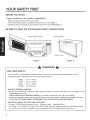
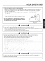
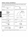
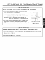
iNSTALLATiON
iNSTRUCTiONS
iNSTRUCCIONES
DEINSTALACION
Models/Modelos
!
721.80032
721.80033
721.80034
721.80039
721.80042
721.80043
i
i
721.80044
721.80049
721.81043
721.85032
721.85033
721.85039
Read and save these
installation instructions,
Lea y guarde estas
instrucciones de
instalaci6n
Part No. MFL39433001
Microwave Hood Combination
Combinaci6n
MicroondasCampana
Sears, Roebuck and Co., Hoffman Estates,IL 60179
www.sears.com
YOUR SAFETY FIRST
BEFORE YOU START
* Proper installation
is the installer's responsibility!
- Read the entire manual before you begin.
- The model number label is located on the oven front. See Figure 1.
- Mounting plate is located on back side of microwave oven. See Figure 2.
BE SURE TO READ THE FOLLOWING
Model
Number
SAFETY iNSTRUCTiONS:
Label
!
Mountinc
Hate
J
Back of
Figurel
Figure 2
WARNING
FOR YOUR SAFETY:
• You wiii need TWO
handled
• AVOID
properly.
people
to install this oven. It is heavy and could cause personal
The dimensions
Height
Width
: 16-7,46 inches
: 29Js,46 inches
Depth
:
Weight
: 51.8
ELECTRICAL
injury if not
of the oven are as follows:
15-1¼6 inches
pounds
SHOCK!
- Before you drill into the wail, note where electrical
ceaied behind the wail.
outlets are and where eiectricai
wires might be con-
YOU COULD GET AN ELECTRIC SHOCK it you contact electrical wires with your drill bit.
- Locate and disconnect the power of any electrical circuits that could be affected
by installing
IF YOU DO NOT DISCONNECT THE POWER, YOU COULD GET AN ELECTRIC SHOCK.
this oven.
• ELECTRICALRATING OF THiS OVEN: 120V, 60Hz.
14 Ampsi1500 Watts (Microwave oven + Cooktop Lamp + Ventilation Fan)
- You need a 120V, 60Hz, AC only, 15A or 20A, fused electrical supply (located in the cabinet above
the microwave as close as possible to the microwave circuit) serving only the microwave.
YOUR SAFETY FIRST
• THIS APPLIANCE
MUST BE GROUNDED!
- if there is an electrical short circuit, grounding reduces the risk of electrical shock by providing
an
escape wire for the electric current. This appliance
is equipped
with a cord having a grounding
wire with a grounding
plug.
PROPERLYPOLARIZED AND
• Place the plug into a properly
See Figure 3.
• Do not use an extension
installed
and grounded
outlet.
GROUNDED OUTLET
cord.
• Keep the power cord dry and do not pinch or crush it.
• DO NOT, UNDER ANY CIRCUMSTANCES, REMOVE
THE POWER SUPPLY CORD GROUNDING
PRONG!
This appliance MUST be grounded!
Three-Pronged (Grounding)
plug
Figure 3
WARNING
Jf you use the grounding
plug improperly,
you risk electric shock!
- Check with a qualified
electrician if you are not sure whether the oven is properly
do not completely
understand the grounding instructions.
DO NOT USE A FUSE IN THE NEUTRAL OR GROUNDING
CIRCUIT.
grounded
or if you
WARNING
improper
grounding
could
SAVE THESE INSTRUCTIONS
result
in electric
shock
or other
FOR THE LOCAL ELECTRICAL INSPECTOR'S
• DO NOT EXPOSE YOURSELF TO EXCESSIVE MICROWAVE
-
DO
DO
DO
DO
DO
NOT
NOT
NOT
NOT
NOT
personal
injury.
USE.
ENERGY!
try to operate the microwave oven with the door open.
tamper with or defeat the safety interlocks.
place objects between the microwave oven front face and the door.
allow soil or cleaner residue to build up on the flat surfaces around the microwave
operate the microwave oven if it is damaged.
- The microwave oven door must close properly
- DO NOT use the microwave oven:
• If the door is bent.
to operate
oven door.
safely.
• If the hinges or latches are broken or loose.
• If the door seals, sealing surfaces or glass is broken.
- DO NOT attempt to adjust or repair the oven yourself!
It should be adjusted and repaired
by a qualified
technician
afterrepairing
the oven.
who can check for microwave
leakage
WARNING
Jf you
do not use the microwave
excessive
microwave
energy.
oven
as instructed,
you
could
be exposed
to
YOUR SAFETY FIRST
• MAKE SURE YOU HAVE ENOUGH
SPACE AND SUPPORT.
- Mount the oven against a flat, vertical wail, so that it is supported by the wail. The wall should be
constructed of minimum 2" x 4" wood studding and 3/8" thick drywall or piaster/lath.
- ATTACH AT LEAST ONE of the two lag screws supporting the oven to a vertical, 2" x 4" waJJ stud.
- DO NOT mount the microwave oven to an island or peninsula cabinet.
- BE SURE the upper cabinet and rear wail structures are able to support 150 Ibs., plus the weight of
any items you place inside the oven or upper cabinet.
- Locate the oven away from strong draft areas, such as windows, doors, and strong heating vents.
- BE SURE you have enough space. See Figure 4 below for minimum vertical and horizontal clearance.
WARNING
if you
do not mount
property
the oven
as instructed,
you
risk
personal
injury
and/or
damage.
i._
Grounded
Plug
30" rain°cabinet opening width
30" rain.clearancefrom bottom
of cabinetto cookingsurfaceor
countertop
(Use templatesincludedwith
installationinstructions)
Figure 4
WARNING
Before you begin
installing
the oven, PLACE A PIECE OF THE CARTON
OR OTHER HEAVY MATERIAL
(a blanket) over the countertop
or cooktop to protect it. Do not use a plastic
Failure to protect these surfaces could result inproperty
damage.
4
cover.
PARTS, TOOLS, MATERIALS
THE FOLLOWING
NOTE: Depending
PARTS ARE SUPPLIED WiTH
on your ventilation
requirements,
Damper/duct
connector
(for roof vented or wall vented installation).
Not Actual
Size
THE OVEN:
you may not use all of these parts.
One power cord clamp and
One dark-colored
mounting screw
(to hold the power cord).
Actual
Size
One power cord clamp bushing - Actual Size
(for the cord hole in a metal upper cabinet).
Four 1/4" x 2" lag screws - Actual Size
(for wall stud holes).
Four 1/4" x 3" toggle bolts - Actual Size
(for drywall holes).
Four 1/4" x 3" bolts - Actual Size
Two tapping screws - Actual Size
(for attaching the damper duct connector)
(for securing to the upper cabinet).
OR
One upper cabinet template
- Not Actual Size
Four spring toggle heads - Actual Size
(for the toggle bolts).
One rear wall template
- Not Actual Size
i
!
NOTE:
You need to install at least one lag screw into a 2" x 4" stud and four anchor
and the mounting
area must meet the 150 Ibs. weight
bolts into the wall,
requirement.
5
PART
TOOL
MATERIALS
YOU WILL NEED THE FOLLOWING
TOOLS AND MATERIALS FOR THEINSTALLATION:
Carton or other heavy
the counter
material
Clear tape
(for taping the templates
Saber
for covering
Stud finder
or thin nail.
to the wail).
saw
(for cutting
top.
Key hole saw (for the power cord hole).
vent holes for roof or wail venting).
Phillips screwdriver
(for the screws).
3/8"
Pencil
and 3/4"
wood drill bits
1/2" and 3/1 6"
drill bits
Fiat blade
screwdriver
Measuring
tape
(for the bolts).
(metal preferred).
Small side cutters or tin snips
Plumb
line
Duct Tape
Caulking
gun
• If you have brick or masonry wails, you need special hardware and tools.
• The ductwork you need for the installation
is not included. Aii wail and roof caps must have a back-draft
damper.
STEP1: PREPARETHEELECTRICALCONNECTIONS
WARNING
AVOID
ELECTRICAL SHOCK[
THIS APPLIANCE
MUST BE GROUNDED[
1. Locate the grounded
electric outlet for this oven in the cabinet
above the oven, as shown in Figure 4 Detail.
NOTE: The outlet should be on a circuit
dedicated
to the
microwave oven 120V, 60Hz., AC only, with a 20ampere
fused electrical supply.
IMPORTANT:
....................
If you do not have the proper wail outlet, you
MUST have one installed by a qualified
electrician.
2. You will cut the power-supply-cord
hole (shown in Figure 4 Detail)
later when you prepare the wail and upper cabinet in Step 4.
NOTE: Do not use an extension cord. Keep the power cord dry and
do not pinch or crush it.
_,
improper
Upper Cabinet
grounding
could
result
1
Grounded
Outlet
Power-Supply-Cord
Hole
Figure 4 Detai[
WARNING
in electric
• DO NOT, UNDER ANY CIRCUMSTANCES,
GROUNDING
PRONG[
This appliance
0
shock
or other
personal
REMOVE THE POWER
injury.
SUPPLYCORD
MUST be grounded[
7
STEP2 : PREPARETHEVENtiNG SYSTEM
NOTE: The ductwork
The standard
you need for outside ventilation is not included with your oven.
ductwork fittings and length are shown in Figure 9, page 9.
WARNING-FIRE
THIS OVEN
HAZARD
MUST BE PROPERLY VENTED!
You may vent your oven in one of three ways:
Roof Venting: If your oven is located on an outside wall near the roof, as in Figure 6 (3-1/4"
and Figure 8 (6" round duct.)
x 10" duct)
Wall Venting: If your oven is located on an outside wail on the first floor of your house, as in Figure 5
(3-1/4" x 10" duct) and Figure 8 (6" round duct.)
Room Venting: If your oven is located on an inside wail of your house, as in Figure 7.
NOTE: if you choose the rear exhaust method (roof or wall venting),
clearance within the wall for the exhaust duct.
Wall
be sure there is enough
Venting
Roof Venting
3-1/4"x10"I I
_-Wall
cap
Ca _i
duct
Oven"
Through-the-wall
I
Roof ca_<_
Wall
_:
[_
IIJl
Through-the-wall
venting
Figure 5
Figure 6
REMEMBER AS YOU INSTALL THE VENTING:
Keep the length of the ductwork and the number
of elbows to a minimum to ventilate your oven
efficiently.
See examples on page 9.
Keep the size of the ductwork
Room Venting
Roof_j>
6" min. _v...---'rf
diameter _._
J Wall cap
round duct I-_'t ...... ".'7_!
the same.
Cabinet
Do not install two elbows
together.
Use duct tape to seal aJJjoints in the duct system.
Use caulking to seal the exterior
opening around the cap.
E,bow'T
3-1/4"
to _-_
waJJ or roof
round
duct
transition
Figure 7
--'.'
I:__"
f(_*_
3-1/4" to round
ductwork transition
Figure 8
STEP2 : PREPARETHE VENTING SYSTEM
STANDARD
NOTE:
If the
FiTTiNGS
existing
extension
damper
duct
duct
is round,
installed
you must
between
use a rectangular-to-round
the damper
assembly
adapter,
and
the adapter
with
a rectangular
to prevent
3"
the
exhaust
caps
must
sticking.
DUCT LENGTH
The total
exceed
length
of the
the equivalent
duct
of
For best performance,
system,
10" to 6" :
90 ° elbow
straight
duct,
elbows,
transitions,
do not use more than three 90 degree
Below are the standard
3-1/4"x
including
wail
or roof
not
140 feet.
fittings
and their equivalent
5ft.
-- I Oft.
3-1/4"xl
3-1/4"xt
elbows.
length in feet.
O" roof cap :
3-1/4"xl
24ft.
45 ° elbow
0" wall cap : 40ft.
= 5ft.
0" 90 ° elbow
3-1/4"xl
:
25ft.
0" flat elbow = 1Oft.
Figure 9
To calculate
the equivalent
length
of each
duct
piece
used,
see the examples
below.
Exam )Jes
For 3-1/4"x10"
For 6" ROUND SYSTEMS
SYSTEMS
6ft. |
Wall
cap
90°
elb°ws
|
6ft" ----_/Wall
ca p
Transition__2f_t.
90 ° elbow
t ....
1 3-1/4" x 10" 90 ° elbow
1 wall cap
8 feet straight duct
TOTAL LENGTH
=
=
=
=
25 ft.
40 ft.
8 ft.
73 ft.
1 transition
2 90 ° elbows
=
=
5 ft.
20 ft.
1 wall cap
8 feet straight
TOTAL LENGTH
=
=
=
40 ft,
8 ft.
73 ft.
9
STEP3 : PREPARETHEVENtiNG BLOWER
Your microwave oven is shipped with the blower assembled for room venting (recirculafing).
You need to adjust the blower if you want wail vented or roof vented installation.
WARNING
ELECTRICAL SHOCK
HAZARD!
UNPLUG
DO NOT PULL OR STRETCH THE BLOWER WtRtNG!
in electrical shock.
1. Remove any shipping
the microwave oven.
materials
UNiT BEFORE WORKING
Pulling and stretching
the blower
ON iT+
wiring
could result
and parts from inside
A thick, protective
covering
2. Cover the counter top or cooktop with a thick,
protective covering to protect it from damage and
dirt. See Figure 10.
NOTE: if you have a free-standing
range, disconnect
it, move it onto a piece of cardboard
or
hardboard
and puil it away from the wail,
so that you can get closer to the upper
cabinet and back wail for easier measuring
and drilling.
3. Remove mounting
plate
Figure 10
plate 2 screws from the mounting
as shown and discard
them. (See Figure 11.)
4. The mounting plate wiil also be used to locate and
mark the mounting holes on the rear wail.
5. Locate exhaust adaptor,
hardware packet.
grease filters and
6. At this point, remove any adhesive tape
(if there is any), on the exhaust adaptor, the grease
filters and the power supply cord.
Figure 11
VENTED INSTALLATION:
Go to STEP 4, PREPARE THE WALL AND UPPER CABINET
located
10
on page
1 3.
plate
-4
Mounting
plate
screw (2 screws)
trol Panel Side
ROOM
Mounting
FOR INSTALLATION
STEP3 : PREPARETHEVENtiNG BLOWER
WALL VENTED
iNSTALLATiON
1. Remove one blower
blower
from
plate
unit mounting
screw and two
screws. Remove the blower
cabinet.
BaCk plate
plate
See Figure 12.
Blower plate
2. Carefully lift the blower unit out of the microwave
oven. Disconnect the blower wire from connector.
See Figure
unting screws
13.
3. Use side cutters or tin snips to cut and remove
knockouts "B"from Back plate.
Discard knockouts. Be careful not to distort
the plate.
See Figure
_.
. /-_I-_
Bower p ate
".o
-_
Blower
unit
mounting
14.
Figure
screw
12
4. Rotate the unit so that the exhaust ports face the
rear of the cabinet. See Figure 15. Before you
insert blower unit, blower wire must be like
Figure 15.
5. Reassemble
the blower
6. Place blower
unit back
into cabinet.
the exhaust ports face towards
cabinet.
7. Reattach
See Figure
the blower
Blower
wire into the connector.
wire
Check that
the rear of the
16.
plate
Connector
to the top of the cabinet
as it was originally assembled. Attach with one
blower unit mounting screw and then two blower
plate mounting
screws. See Figure 17.
8. Go to STEP 4, PREPARE THE WALL
CABINET FOR INSTALLATION
Figure 13
AND UPPER
located
on page
13.
Blower
_
unit
"B"
Exhaust
ports
Figure 15
Figure 14
m?unJ_ng
B_cOWer
plate
Blower unit _
"-o
Exhaust
ports
exhaust ports
Blower unit
mounting screws
Figure 16
Figure
17
11
STEP3 : PREPARETHEVENtiNG BLOWER
ROOF VENTED
iNSTALLATiON
1. Remove one blower
blower
from
plate
cabinet.
2. Carefully
oven.
unit mounting
screw and two
screws. Remove the blower
plate
Blower
See Figure 18.
lift the blower
plate
unit out of the microwave
unting
3. Rotate blower
unit 90 ° so the exhaust
ports face
Blower
the top of the cabinet.
4. Place blower
unit back
See Figure
screws
plate
Blower
19.
into microwave
unit
mounting
screws
Figure 18
oven.
5. Use side cutters or tin snips to cut and remove
knockouts '_A'_ from blower plate.
Discard knockouts. Be careful not to distort
plate.
the
See Figure 20.
6. Reattach blower plate to microwave oven.
Attach with the one blower unit mounting screw
and then the two blower
See Figure 21.
plate
mounting
Blower
unit
screws.
Figure 19
Knockots "A"
Blower
plate
Figure 20
Blower
unit
Blower plate
-.
Blower
plate
mo_unting
Blower unit
mounting
Figure 21
12
screws
screws
STEP
4: PREPARE
THEWALL
ANDUPPER
CABINET
FOR/NSTALLATiO
MEASURE AND TACK / TAPE UP
THETEMPLATE
1. Using o plumb line and (metal) measuring tope,
find. and mark the vertical center line(_)on
the
back wail, as in Figure 22.
O
2. Find and mark one or two points where the studs
ore on the wall (Studs ore normally 16 inches apart).
and then measure and mark the stud locations.
if you cannot find any wall stud, consult o local
building contractor.
CAUTION
DO NOT ATTEMPT TO iNSTALL THE
MICROWAVE
OVEN iF YOU CANNOT
FiND A WALL
STUD.
3. Line up the plumb line on the wail with the center
line on the mounting plate.
NOTE: Be sure the minimum
width
Figure 22
is 30 inches and
the distance from the top of the mounting
plate to the range or counter top is at least
30 inches. See Figure 4 on page 4.
4. Center mounting plate in opening by lining up the
plumb line on wail with centeriine on mounting plate.
Make sure the minimum width is 30 inches and that
upper
o
cabinet
templafe
,-_._._-_?
o
oo
the top of the mounting plate is located o minimum
of 30 inches above the cooking surface.
See Figure 23.
J!
NOTE: if the front edge of the cabinet is lower
than the back edge, adjust the mounting
plate tobe
level with the cabinet
__
(3 Diecesmountina
_ate/
(3 pieces mounting plate)
"4
--
front.
5. Measure the bottom of the upper cabinet frame.
Trim the edges "A", "B" and "C" on the upper
cabinet template so that the template wJJJfit on
the bottom of the upper cabinet, if upper cabinet
has o recessed frame, trim template so that it fits
inside the recessed area. Align the centeriine of
the upper cabinet template with the centeriine of
the mounting plate; then securely tape or tack the
upper cabinet template in place. See Figure 23.
Figure 23
13
STEP
4: PREPARE
THEWALL
ANDUPPER
CABINET
FORINSTALLATION
DRILL THE HOLES iN THE WALL AND UPPER CABINET.
WARNING
BE VERY CAREFUL WHEN
Electrical
wires could
them
could
you
get
an
DRiLLiNG
be concealed
HOLES iNTO THE WALL.
behind
the wall covering
and if the drill
hits
electric shock.
1. Find the points on the mounting plate Jabeled "A', "B', "C"and "D". Drill a 3/16"
diameter hole at any
of these points that are in front of a waJJ stud. DrHJ a 3/4" diameter hoJe at any of these points that are
over drywaJL
2. DriJJ a 3/8" hoJe at points "J" and "K" on the upper cabinet template.
NOTE: If the bottom of the upper cabinet is recessed 3/4" or more, you wHJ need 2"x2" filler blocks
(not incJuded) to provide additionaJ support for the boJts. See Figure 24.
• Mark the center of each filler block and driJl a 3/8" diameter hoJe at the mark.
• AJign fiiJer blocks over the two openings in the top of the microwave oven cabinet and attach to
cabinet with masking tape. See Figure 25.
3. Cut or driJJ a 2" diameter hoJe at the area marked "M', "power supply cord hoJe" on the upper cabinet
template.
If the upper cabinet is metaJ, you wiJJ need to cover the edge of the hoJe with the power supply
cord bushing (supplied) to prevent damage
to the cord from the rough metal edge.
WARNING
YOU MUST COVER THE EDGE OF
Cabinet front Filler block
f
THE POWER SUPPLY CORD HOLE iN
A METAL CABINET WITH THE POWER
Cabinet
bottom shelf
f
SUPPLY CORD BUSHING. FAILURE TO
DO SO COULD RESULT iN DAMAGE
TO THE CORD AND ELECTRIC SHOCK°
Figure 24
4. Cut out the venting areas (with the saber saw):
• Roof Venting: cut out the shaded area marked
"L" on the upper cabinet tempJate.
WaJJ or Room Venting (RecircuJating): go to
STEP 5, INSTALL THE MOUNTING
PLATE,
Jocated on page 15.
Filler block
5. Use caulking compound to seal the exterior wail
or roof opening around the waJJ cap or roof cap.
Figure 25
14
STEP5 • INSTALLTHEMOUNTING PLATETO THEWALL
THE OVEN MUST BE CONNECTED
AT LEAST ONE WALL STUD
1. Draw a vertical
TO
line on the wall at the center of
the 30" wide space.
Use the mounting plate as the template for the
rear wall. Place the mounting plate on the wall,
making sure that the tabs are against the bottom
of the cabinet. Line up the notch and center line
on the mounting plate to the center line on the wall.
3/1 6" Hole on Studs
Hole on Dry wall Only
3/4"
Minimum 66" i
l
I II
|
he
III
ForWoU-
enteOn,y
LT!
I'!pcl_-"
2. While holding the mounting plate with one hand,
draw circles on the wall at holes "A", "B", "C"and
"D". Four holes must be used for mounting.
If the holes are not used, the installation will not
;:/I
be secure. Installer must use these holes for proper
installation. Use toggle bolts through these holes
/
unless one of them lines up with a stud.
Use awood screw for studs. See Figure 26.
/
_1
°7"
o41
I )t
Draw Lines
, \
on Studs
i
\
NOTE: Draw a fifth circle inside area "E", through
one of the holes to match the location of
astud.
For wall vented: The oven requires a rear wall cutout
opening for the rear wall duct and the exhaust
adaptor must be attached to the mounting plate.
See the next page on how to prepare the rear wail
cutout opening and the exhaust adaptor/mounting
plate for wail vented.
3. Drill holes through the circles. If there is a stud, drill
a 3/16" hole for lag screws. Two or preferably
four lag screws at holes "A"and "C", or "B" and "C"
must be used to secure mounting plate
If there is no stud, drill a 3/4" hole for
Make sure to use at least I lag screw
area "E" in a stud, and 4 toggle bolts
"B", "C" and "D" in the drywall
t
i
_
Support Tab
(3 pieces mounting plate)
Figure 26
or the plaster.
wall to mount the bracket. You may pull forward
on the bracket to help in tightening the toggle bolts.
t
Support Tab
to wall.
toggle bolts.
at holes of
at holes "A",
4. Attach the plate to the wall. To use spring toggle
head bolts: Remove the toggle wings from the bolts.
Insert the bolts into the mounting plate and replace
the spring toggle heads to 3/4" past the bolt ends.
Insert the spring toggle heads into the holes in the
J
,
Space More Than Wall Thickness
Mounting-_Toggle
Hate
Wings
f
_
Bolt
End
Wall
Tighten all bolts. See Figure 27.
Figure 27
15
STEP5" INSTALLTHEMOUNTING PLATETO THEWALL
TO PREPARE THE REAR WALL
CUTOUT
OPENING AND EXHAUST ADAPTOR//
MOUNTING
PLATE FOR WALL VENTING
AND ROOF VENTING:
NOTE: if room vented
installation
is used, skip this step.
1. Using the Wail-template.
This template wiii give the
location and size of the box cutout for the rear wail
duct as described
in step 5 item 1(page
15)
t
2. Using a pencil, put dots through slots "F"and "G",
and through holes "H" and "i". Remove the mounting
plate and draw lines extending through the points.
This will give the location and size of the box cutout
for the rear wall duct. See Figure 28.
REAR
WALLTEMPLATE
Figure 28
Attach the exhaust adaptor to the rear mounting
plate by sliding it into the guides at the top center
of the plate on the wail side. Push in securely unfi
lit is past the top locking tabs and in the lower
locking tabs. Take care to assure the damper
hinge is installed so that it is at the top and that
the damper swings freely.
• Carefully guide the exhaust adaptor, now atached
to the mounting plate, into the house duct, before
using the screws to attach the plate to the wall.
This wiil assure proper alignment for installation.
See Figure 29.
Damper
(hinge side up)
Adaptor
Mounting Hate
(wall side)
Slide exhaust
adaptor
into
guides
panel.
on rear
i
• Return to step 5, item 3 (page 15) to continue.
After completing the installation of the mounting
plate, again check the rear damper for free
movement to assure it will operate properly.
Guide
Figure 29
16
STEP6 :ATTACHTHEOVEN TO THEWALL
_,
WARNING
_,
You will need two people to lift this
microwave.
Failure to use more than
one person could
injury.
II
Power cord
result in personal
cord
hoie
1. Carefully lift microwave oven and hang it on
support tabs (See Figure 26) at the bottom of the
mounting plate. Reaching through upper cabinet,
thread power supply cord through the power supply
cord hole in the bottom of the upper cabinet.
See Figure 30.
2. Rotate the microwave oven upward so the top of
oven is against the bottom of the upper cabinet or
cabinet frame.
\
Figure 30
3. Then insert a bolt down through each hole in the
upper cabinet bottom. See Figure 31.
Tighten the bolts until the gap between the upper
cabinet and microwave oven is closed.
4. If wail vented or room vented installation
go to No. 7 on the next page.
is used,
Figure 31
17
STEP6 :ATTACHTHEOVEN TO THEWALL
5. Roof vented installation: See Figure 32.
Install ductwork through the vent opening in the
upper cabinet. Complete the venting system through
the roof according
to the method needed.
See _°PREPARETHE VENTING SYSTEM," STEP 2 on
the page 8. Use caulking to seal exterior roof
opening around the exhaust cap. See Figure 6 on
page 8.
Figure 32
6. Use power supply cord damp to bundle the power
supply cord. Install the power supply cord damp,
using a screw as shown in Figure 33, to inside of
the cabinet.
7. To install the grease filter: Slide it into the sJide sJot,
then push up and toward oven center to lock.
See Figure 34.
8. Plug in the power
supply cord.
i
I
IM /_l P°wer
9. Read your Owner's Manual, then check the
operation of your microwave oven.
clamp
Figure 33
Figure 34
18
Printed in china