1
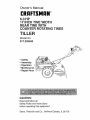
Owner's Manual
CRnFTSMnN
o
6.0 HP
17 INCH TINE WIDTH
REAR TINE WITH
COUNTER ROTATING TINES
TILLER
Model No,
917.293400
•
•
°
°
Safety
Assembly
Operation
Maintenance
° Repair Parts
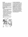
CAUTION:
Read and follow all
Safety Rules and Instructions
before operating this equipment
Sears,
Roebuck
and Co., Hoffman
Estates,
IL 60179
Warranty .: ...............................................
2
Safety Rules ............................................
2
Product Specifications
........................... 4
Assembly ................................................
5
Operation ............................................
3 & 8
Maintenance .........................................
13
LIMITED
TWO YEAR WARRANTY
Service and Adjustments ...................... 15
Storage ..........................................
3 & 19
Troubleshooting
....................................
20
Illustrated Parts List .................................... 22
Parts Ordering
ON CRAFTSMAN
.......................
Back Cover
TILLEB
For two (2) years from date of purchase, when this Craftsman Tiller is maintained,
lubricated, and tuned up according to the operating and maintenance instructions in the
owner's manual, Sears will repair free of charge any defect in material or workmanship.
This Warranty does not cover:
• Expendable items which become worn during normal use, Such as tines, spark plugs,
air cleaners and belts.
-
Repairs necessary because of operator abuse or negligence, including bent crankshafts and the failure to maintain the equipment according to the instructions contained in the owner's manual.
o If this Craftsman Tiller is used for commercial or rental purposes, this Warranty
applies for only thirty _30) days from the date of purchase,
Warranty service is available by relurning the craftsman power mower to the nearest
sears service center/department
in the united states. This warranty applies only while
this product is in use in the united states.
This Warranty gives you specific legal rights, and you may also have other rights which
vary from state to state.
SEARS, ROEBUCK AND CO., D/817WA, HOFFMAN ESTATES, IL 60179
•
TRAINING
• Read lhe Owner's Manual carefully. Be
thoroughly familiar with the controls and
the proper use of the equipment. Know
how to stop the unit and disengage the
controls quickly.
° Never allow children to operate the
equipment.. Never allow adults to operate the equipment without proper
instruction
. Keep the area of operation clear of all
persons, particularly small children, and
pets_
PREPARATION
• Thoroughly inspect the area where the
equipment is to be used and remove all
foreign objects°
• Disengage all clutches and shift into
neutral before starting the engine (motor).,
. Do not operate the equipment without
wearing adequate outer garments. Wear
footwear that will improve footing on
slippery surfaces,
• Handle fuel with care; it is highly flammable.
° Use an approved fuel container.
° Never add fuel to a running engine or
hot engine.
• Fill fuel tank outdoors with extreme care
Never fill fuel tank indoors.
• Replace gasoline cap securely and
clean up spilled fue! before restarting.
° Use extension cords and receptacles as
specified by the manufacturer
for all
units with electric ddve motors or electric
starling motors.
° Never attempt to make any adjustments
while the engine (motor) is running
(except where specifically recommended by manu!acturer).
OPERATION
MAINTENANCE
• Do not put hands or feet near or under
rotating parts.
• Exercise extreme caution when operating on or crossing gravel drives, walks,
or roads° Stay alert for hidden hazards
or traffic. Do not carry passengers.
,, After striking a foreign object, stop the
engine (motor), remove the wire from
the spark plug, thoroughly inspect the
tilier for any damage, and repair the
damage before restarting and operating
the tiiler_
•
• Exercise caution
falling°
• If the unit should
to avoid slipping or
start to vibrate abnor-
mally, stop the engine (motor) and check
immediately
for the cause. Vibration is
generally a warning of trouble.
• Stop the engine (motor) when leaving
the operating position.
• Take all possible precautions when leaving the machine unattended.
Disengage
the tines, shift into neutral, and stop the
engine.
• Before cleaning, repairing, or inspecting,
shut off the engine and make Certain all
moving parts have stopped. Disconnect
the spark plug wire, and keep the wire
away from the plug to prevent accidental
starting,. Disconnect the cord on electric
motors.
o Do not run the engine indoors; exhaust
fumes are dangerous,
° Never operate the tiller without proper
guards, plates, or other safety protective
devices in place.
o Keep children and pets away.
• Do not overload the machine capacity
by attempting to till too deep at too fast a
rate.
• Never operate the machine at high
speeds on slippery surfaces. I..ook
behind and use care when backing.
• Never allow bystanders near the unit.
° Use only attachments
and accessories
approved by the manufacturer
of the
tiller (such as wheel weights, counter _
weights, cabs, and the like).
• Never operate the tiller without good visibility or light.
° Be careful when tilling in hard ground.
The tines may catch in the ground and
propel the tiller forward, tf this occurs,
let go of the handlebars and do not
restrain the machine.
AND
STORAGE
Keep machine, attachments,
and
accessories in safe working condition.
° Check shear pins, engine mounting
bolts, and other bolts at frequent intervals for proper lightness to be sure the
equipment is in safe working condition°
• Never store the machine with fuel in the
fuel tank inside a building where ignition
sources are present, such as hot water
and space heaters, clothes dryers, and
the like. Allow the engine to cool before
storing in any enclosure.
• Always refer tO the operator's guide
instructions for: important details il the
tiller is to be stored for an extended periodo
•_kCAUTION:
Always disconnect spark
plug wire and
contact spark
dental starting
ing, adjusting
WARNING
place wire where it cannot
plug in order to prevent acciwhen setting up, transportor making repairs.
The engine exhuast from this product contains chemicals known to the State of
California to cause cancer, birth defectd, or
other reproductive harm.
PRODUCT
SPECIFICATIONS
MAINTENANCE
AGREEMENT
A
Sears
Maintenance
Agreement is avail-IORSEPOWER:6.0HP
able on this product° Contact your nearest
DISPLACEMENT:
11o88
CU.tN.
Sears store for details.
GASOLINE
CAPACITY: 4 Quarts
CUSTOMER RESPONSIBILITIES
UnleadedRegular
• Read and observe the safety rules_
OIL(API-SF/SG/SH): SAE30
° Follow a regular schedule in maintain(Above32°F)
ing, caring for and using your tiller°
CAPACITY:
20oz.)
SAE5W-30
° Follow the instructions under the
(Below32°F)
"Customer Responsibilities"
and "StorSPARKPLUG:
ChampionN4C
age" sections of this Owner's Manual.
GAP:.030")
Congratulations
on your purchase of a
Craftsman Tiller. It has been designed, engineered and manufacttJred
best possible dependability
ance,
to give you the
and perform-
Should you experience any problems you
cannot easily remedy, please contact your
nearest authorized Sears Service
Center/Department.
We have competent,
well-trained technicians
and the proper
tools to service or repair this unit.
Please read and retain this manual The
instructions will enable you to assemble
and maintain your tillerproperly,
Always
observe the "SAFETY RULES'L
Your new tiller has been assembled at the
factory with exception of those parts teft
unassembfed for shipping purposes.
To
ensure safe and proper op6ration of your
tiller all parts and hardware you assemble
must be tightened securely.
Use the correct tools as necessary to insure proper
tightness.
WARNING:
This unit is equipped with an
internal combustion engine and should not
be used on or near any unimproved forestcovered, brush-covered
or grass covered
land unless the engine's exhaust system is
equipped with a spark arrester meeting
applicable local or state laws (if any). If a
spark arrester is used, it should be maintained in effective working order by the
operator.
tn the state of California the above is
required by law (Section 4442 of the
California Public Resources Code). Other
states may have similar laws. Federal
Iaws apply on federal lands, See your
Sears Authorized Service Center for spark
arrester. Refer to the Repair Parts section
of this m_nual for part number.
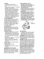
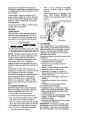
These accessories were available when the tiller was purchased.
They are also available at most Sears Retail outlets and Service Centers. Most Sears Stores can order
repair pads for you when you provide the model number of your tiller.
ENGINE
AiR F_LTER
'GAS CAN
i
TILLER PERFORMANCE
FURROWOPENER
TILLER MAINTENANCE
BELT
'
SHEAR_PIN
i
HAtRP{N
CL!=
p
Your new tiller has been assembled at the factory with exception of those parts left
unassembled
for shipping purposes,
To ensure safe and proper operation of your tiller
all parts and hardware you assemble must be tightened securely.
Use the correct tools
as necessary to insure proper tightness.
TOOLS
REQUIRED
FRONT
FOR ASSEMBLY
A socket wrench set will make assembly
easier. Standard wrench sizes are listed.
(1) Utility knife
(1) Wire cutter
(1) Tire pressure gauge
(1) Screwdriver
(1) Pair of pliers
(1) 9/16" wrench
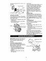
OPERATOR'S POSITION
When right or left hand is mentioned in
this manual, it means whenyou
are in
the operating position (standing behind
tiller handles),
RIGHT
LEFT'
OPERATOR'S
POSITION
i
i
JJ,_'uJJ
CONTENTS
i,m
i
1±±
LL
.
OF HARDWARE
Locks
(I) Carriage Bolt
3/8-16 UNC x 1 Gr, 5
(2) Hairpin
IHIH'I
PACK
Q
//llllfifY
(2) Handle
I
(1) Center Locknut
3/8-16 UNC
(1) Cable Clip
Clips
(1) Pivot Bolt
3/8-16 UNC Grade 5
(1) Flat Washer
13/32 x 1 x 11 Ga,
0
Extra Shear
©
Pins & Clips
(1) Handle
L.oc_L_v_r_
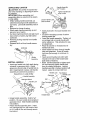
UNPACKING
CARTON
,,._,,_
Handle Assembly
"uP"Posilfoo
,_OAUTION:
Be careful of exposed staples when handling or disposing of cartom
ing material,
IMPORTANT:When
unpacking and
assembling tiller, be careful not to stretch
or kink cables.
"::'+:_::_ Tighten handle lock
Loose__
_.'_,_'_
_
• While holding handle assembly, cut
cable ties securing handle assembly to
top frame. Let handle assembly rest on
tiller.
. Remove top frame of carton.
• Slowly ease handle assembly up and
place on top of carton.
• Cut down right hand front and right hand
rear corners of carton, lay side carton
wall down.
, Remove packing material from handle
assembly.
° Separate shift rod from handle assembly.
o
°
0
°
°
_.,m
"---..
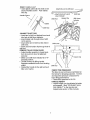
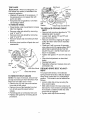
INSTALL
t
HANDLE
J
Assembly
' ' '
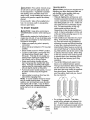
° Insert one handle lock (with teeth facing
outward) in gearcase notch. (Apply
grease on smooth side of handle lock to
aid in keeping lock in place until handle
assembly is lowered into position.)
Viewed from r.h. side of tiller
\'_"v_"
_.__.,
/Handte
Assembly
Gearcase Notch
/
Handle Lock
Insert pivot bolt in front part of plate and
lighten.
Cut down remaining corners of carton
and lay panels flat.
Lower the handle assembly.
Tighten nut
on carriage bolt so handle moves with
some resistance.
This will allow for easier adjustment.
Place flat washer on threaded
handle lock lever.
Insert handle lock {ever through handle
base and gearcase.
Screw in handle
lock {ever just enough to hold {ever in
place,
Insert second handle lock (with teeth
inward) in the slot of the handle base
(just inside of washer).
Raise handle assembly to highest position and securely tighten handle lock
lever by rotating clockwise.
Leaving
handle assembly in highest position will
make it easier to connect shift rod.
Handle Lock
Gearcase
Flat Washer
\
Handle Lock
Slot
Rear Cartridge
Boft
- ._.
Handle Base
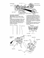
. Grasp handle assembly° Hold in "up"
position.
Be sure handle lock remains in
gearcase notch. Slide handle assembly
into position.
• Rota[e handle assembly down. Insert
rear carriage bolt first, with head of bolt
on LH. side of titler and loosely assemble locknut.
end of
Locknut--
Pivot Bolt
INSEHT
[;ABLI=
ULtt _
° Insert plastic cable clip into hole on the
back of handle column
Push cables
into clip,
Attach thts end to shift lever
-.-,.._
LL"_,Atlach this End To shift "_'_" Shift Rod
Handle Column
Lever Indicator
Shift Rod
Hairpin Clip
Shift Lever
Indicator
Cables
Cable Clip
CONNECT SHIFT ROD
. Insert end of shift rod farthest from bend
into hole of shift lever indicator,
o Insert hairpin clip through hole of shift
rod to secure.
o Insert other end of shift rod into hole in
shift lever,
° Insert second hairpin clip through
shift rod.
REMOVE TILLER FROM CRATE
Shift Lever
hole of
° Adjust handle assemby to lowest position, Be sure lock lever is tightened
securely°
. Make sure shift lever indicator, is in "N"
(neutral) position.
° Tilt tiller forward by' lifting handle,
Separate cardboard cover from leveling
shield,
• Rotate tiller handle to the right and pull
tiller out of carton,
CHECK TIRE PRESSURE
The tires on your unit were overinfIated at
the factory for shipping purposes,
Correct
and equal tire pressure is important for
best tilling performance.
• Reduce tire pressu[e to 20 PSI,
HANDLE HEIGHT
° Handle height may' be adjusted Io better
suit operator° (See "TO ADJUST HANDLE HEIGHT'
in the Service and
Adjustments
section
of this manual)_
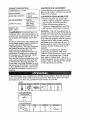
Thesesymbols mayappearon yourTElleror in literaturesuppliedwitl_the product.
Learnandunderstandtheir meaning.
T_,LI#(_
FO;_,Vi_D
KNOW
N_UT_I
F_EE
CkUT_ON
Et,_GIHE
5t',_G_E
_5T
OR WARNING
Ot_
MANUAL
AND SAFETY
SLO_
FUEL
CHOK_
OFF
YOUR TILLER
READ THIS OWNER'S
TILLER.
RULES BEFORE
OPERATING
YOUR
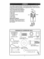
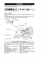
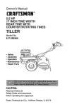
Compare the illustrations with your tiller to familiarize yourself with the location of various controls and adjustments.
Save this manual for future reference,
Drive Control Bar
Throttle Control
Primer
"",,.\
Shift Lever Indicator
Depth Stake-._
Leveting Shield---..
Recoil
Starter
Handle
Outer Side Shield
MEETS ANSI SAFETY
Our tillers conform
DRIVE
tines.
CONTROL
DEPTH STAKE
tiller will dig.
LEVELING
to the safety standards
BAR - Used to engage
- Controls
SHIELD
depth
- Levels tilled soil.
OUTER SIDE SHIELD - Adjustable
tect small plants from being buried.
THROTTLE
engine
speed.
at which
CONTROL
to pro-
- Used to conlrol
REQUIREMENTs
of the American
..........
National
-"
Standards
Institute.
SHIFT LEVER
- Used to shift transmission
gears,
SHIFT LEVER
INDICATOR
- Shows which
gear the transmission
is in.
RECOIL
HANDLE
start'the
STARTER
- Used
to
engine.
PRIMER - Pumps additonat
fuel from the
carburetor
to tile cylinder
for use when
starting a cold engine,
The operationol anytillercan resultin foreignobjectsthrownintothe eyes,
whichcan resultin severeeye damage.Alwayswear safetyglassesor eye
shieldsbeforestartingyourtiller andwhiletilling,We recommenda wide
visionsafetymaskoverthe spectaclesor standardsafety glasses.
HOW
TO USE
YOUR
TILLER
Know how to operate all controls before
adding fuel and oil or attempting to start
engine+
STOPPING
TINES AND DRIVE
° Release
ment.
drive control bar to stop move-
• Move shift fever to "N +'(neutral)
ENGINE
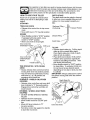
DEPTH STAKE
The depth stake ban be raised or lowered
to allow you more versatile tilling and cultiyating, or to more easily transport your
tiller+
Shallowest Tilling +......
(Cultivating)
%
"" Transport Position
position.
• Move throttle control to "STOP" position+
If equipped with stop switch, move
switch Io "STOP" position.
• Never use choke to stop engine.
Drive Control Bar
"ENGAGED" Position
Shift Lever
Deepest "Riling
Depth Stake.
TILLING
Drive
Bar
"DISENGAGED"
Position
Throttle
TINE OPERATION
DRIVE
- WITH
WHEEL
° Always release drive control bar before
moving shift lever into another position.
+ T_ne movement is achieved by moving
shift lever to ( _ ) fill position and
engaging drive control bar.
FORWARD - WHEELS ONLY/TINES
STOPPED
• Release drive control bar and move shift
• Release depth stake pin. Pull the depttl
stake up for increased tilling depth.
Place Depth stake pin ir_ hole of depth
stake to lock in position.
• Place shift lever indicator in till position+
• Hold the drive control bar against the
handle to start telling movement.
"Fines
and wheels will both turn,
° Move throttle control to "FAST" position
for deep tilling. To cultivate, throttle control can be set at any desired speed,
depending on how fast or stow you wish
to cultivate+
IMPORTANT: Always release drive control
bar before moving shift lever into another
position.
Depth Stake Pin
SED" Position
\
lever indicator to "F" (forward) position.
Engage drive control bar and tiller will
move forward..
REVERSE - WHEELS ONLY/TINES
STOPPED
• DO NOT STAND DIRECTLY BEHIND
TILLER,
• Release the drive contro! bar+
• Move throttle control to "SLOW" posF
tion,
, Move shift lever indicator to "R"
(reverse) position.
° Hold drive control bar against the handle
to start tiller movement+
"Locked"
Position
Nut "B"
Nut "A"
Outer Side Shield
TURNING
• Release tile drive control bar.
. Move throttle control to "SLOW"
tion.
posi-
• Place shift lever indicator in "F" (forward)
position. Tines will not turn.
- Lift handle to raise tines out of ground.
o Swing the handle in the opposite direction you wish to turn, being careful to
keep feet and legs away from tines.
• When you have completed your turnaround, release the drive control bar and
lower handle, Place shift lever in till
position and move throttle control to desired spbed_ To begin tilling, hold drive
control bar against the handle.
OUTER SIDE SHIELDS
The back edges of the outer side shields
are slotted so that the shields can be
raised for deep tilling and lowered for shallow tilling to protect smaif plants from
being buried
Loosen nut "A" in slot and
nut "B". Move shield to desired position
(both sides)° Retighten'nuts,
CHECK ENGINE OIL LEVEL
,, The engine in your unit has been
shipped, from the factory, already filled
with SAE 30 summer weight oil,
. Be sure tiller is level and the area
around oil fill is clean,
• Check oil level before each use. Add oil
if needed. Fill to full line on dipstick,
• To read proper level, tighten engine oil
cap each time.
Reinstall engine oil cap and tighten.
For approximate capaci!_/see 'PRODUCT SPECIFICATIONS
on page 4 of
this manual, All oil must meet A P.I.
Service Classification
SF, SG or SH,
° For cold weather operation you should
change oil for easier starting (See oil
viscosity chart in the Customer
Responsibilities
section of this manual).
° To changeengine
oil, see the Customer
Responsibilities
section in this manual.
"_""'-.-,
Oil Fill
TO TRANSPORT
_CAUTION:
Before
lifting or transpodCap/Dipstick
ing, allow tiller engine and muffler to cool.
Disconnect spark plug wire. Drain gasoline from fuel tank.
AROUND
THE YARD
ADD GASOLINE
° Release the depth stake pin. Move the
depth stake down to the top hole for
transporting the tiller. Place depth stake
pin in hole of depth stake to lock in position, This prevents tines from scuffing
the ground.
. Place shift lever indicator in "F" (forward)
position for transporting.
• Hold the drive control bar against the
handle to start tiller movement
Tines
will not turn.
° Move throttle control to desired
AROUND TOWN
° Fill fuel tank. Use fresh, clean, regular
unleaded gasoline.
(Use of leaded
gasoline will increase carbon and lead
oxide deposits and reduce valve life.
IMPORTANT: When operating in tempera,_
tures below 32°F (0°C), use fresh, clean,
winter grade gasoline to help insure good
cold weather starting.
WARNING: Experience indicates that alcohol blended fuels (called gasohol or using
ethanol or methanol) can attract moisture
which leads to separation and formation of
acids during storage. Acidic gas can damage the fuel system of an engine while in
storage_ To avoid engine problems,
the
fuel system should be emptied before
storage of 30 days or longer. Drain the
gas tank, start the engine and let it run
until the fuel lines and carburetor are
speed.
° Disconnect spark plug wire.
• Drain fuel tank,
° Transport in upright position
oil leakage.
BEFORE
STARTING
to prevent
ENGINE
IMPORTANT:
Be very careful
dirt to enter the engine when
adding oiF or fuel. Use clean
and store in approved, clean,
tainers,, use clean fill funnels,
not to allow
checking or
oit and fuel
covered con-
empty. Use fresh fuel next season. See
Storage section of this manual for additional information,
Never use engine or carbu.,
retor cleaner products in the fuel tank or
permanent damage may occur.
tt3
,_CAUTtON"
TILLINL_
Fill to within 1/2 inch of top
,_CAUTION:
Until you are accustomed to
handling your tiller, start actual field use
with throttle in slow position (mid-way
between "FAST" and "IDLE").
° Tilling is digging into, turning over, and
breaking up packed soil before planting.
Loose, unpacked soil helps root growth.
Best tilling depth is 4" to 6". A tiller will
also clear the soil of unwanted vegetation. The decomposition
of this veg.
etable matter enriches the soil.
of fuel tank to prevent spills and to allow
for fuel expansion° If gaso{ine _saccidentally spilled, move machine away from
area of spill° Avoid creating any source of
ignition until gasoline vapors have disappeared.
Do not overfill. Wipe off any spilled oil or
fuel. Do not store, spill or use gasoline
near an open flame.
TO START
HINT_
ENGINE
,_CAUTION:
Keep drive control bar in
"DISENGAGED"
position when starting engine,,
When starting engine for the first lime dr if
engine has run out of fuel, it will take extra
pulls of the recoil starter to move fuel from
the tank to the engine,
• Make sure spark plug wire is properly
connected.
• Moveshift
lever indicator to "N" (neutral)
position,
• Place throttle control in "FAST" position.
• To start a cold engine, push primer five
(5) times before trying to start. Use a
firm push. This step is not usually necessary when starting an engine which
has already run for a few minutes.
° Grasp recoil starter handle with one
hand and grasp tiller handle with other
hand. Pul/rope cut slowly until engine
reaches start of compression
cycle (rope
wJtl pull slightly harder at this potnt)o
o Pull recoil starter handle quickly. Do not
let starter handle snap back against
starter.
• Allow engine to warm up for a few minutes before engaging lines,
NOTE: In cooler weather it may be necessary to repeat priming steps. In warmer
weather over priming may cause flooding
andengine
wilt not start° tf you do flood
engine, wait a few minutes before attempt.ing to start and do not repeat priming
steps,
Depending on the climate (rainfall and
wind), it may be advisable to till the soil
at the end of the growing season to further condition the soil.
• Soil conditions are important for proper
tilling. Tines will not readily penetrate
dry, hard soil which may contribute to
excessive bounce and difficult handling
of your tiller. Hard soil should be moistened before filling; however, extremely
wet soil will "ball-up" or clump during tilling. Wait until the soil is tess wet in order
to achieve the best results. When tilling
in the fall, remove vines and long grass
to prevent them from wrapping around
the tine shaft and slowing your tilling
operation.
- You will find tilling much easier if you
leave a row untilled between passes.
Then go back between tilled rows.There
are two reasons for doing this. First,
wide turns are much easier to negotiate
than about-faces.
Second, the tiller
won't be pulling itself, and you, toward
the row next to it.
7_
/j
i,z
//
g
f/
rj
z
//
N
/J
g
Do not lean on handle.
Primer_
This takes
weight off the wheels and reduces traction, To get through a really tough section of sod or hard ground, apply upward
pressure on 'handle or lower the depth
stake.
Recoil
Starter
Handle
11
CULTIVATING
Cultivatingis destroyingthe weeds
betweenrowsto preventthem fromrobbing nourishmentand moisturefromthe
plants,At the sametime, breakingup the
upperlayerof soil crustwill help retain
moisturein the soil, Bestdiggingdepthis
I" to3" (2.5-7,5cm). Lowerthe outerside
shieldsto protectsmallplantsfrom being
buried.
o Cultivateup anddown the rowsat a
speedwhichwil!allow tinesto uproot
weedsandleavethe groundin rough
condition,promotingno furthergrowthof
weedsandgrass_
O OIO C)10
O OIO OIO
O ©iO O_O
O ,OIOOIO
TINE SHEAR PINS
The fine assemblies on your tiller are
secured to the fine shaft with shear pins
(See 'q'INE REPLACEMENT" In the
Service and Adjustments section of this
manual).
If the tiller is unusually overloaded or
jammed, the shear pins are designed to
break before in_rnal damage occurs to
the transmission.
° If shear pin(s) break, replace only with
those shown in the Repair Parts section
of this manual
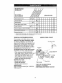
:SERV CE DATES
Check Engine Oil Level
t_
If
Change
E.glneo,
_,2
Oil Pivot Points
Inspect Spark Attester / Mutfter
Inspect Air Screen
V e
Clean or Replace Air Cleaner Cartridge
Clean Engine Cylinder Fins
If
Replace Spark Plug
! - Ch_flge more often when opersling under a heavy toad a_ in high amblenl temperntures
2 SeatO0 more often when operating In dt_y or dos_ conditions.
r'
GENERAL RECOMMENDATIONS
LUBRICATION
The warranty on this tiller does not cover
items that have been subjected _ operator abuse or negligence.
To receive full
value from the warranty, the operator must
maintain tiller as instructed in this manual.
CHART
Throttte Control
Some adjustments will need to be made
periodically to properly maintain your tiller.
All adjustments in the Service and
Adjustments section of this manual should
be checked at least once each season.
*" Engine
• Once a year you should replace the
spark plug, clean or replace air filter, and
check tines and belts for wear, A new
spark plug and clean air filter assure
proper air-fuel mixture and help your
engine run better and last longer.
BEFORE EACH USE
• Check engine oil level.
• Check tine operation.
• Check for loose fasteners.
LUBRICATION
Keep unit welt lubricated
TION CHART").
(See "LUBRICA-
[
"
' * Wheel Hub
* Idler Bracket
* SAE 30 OR 10W-30 MOTOR OIL
_* REFER TO CUSTOMER
RESPONSIBILITIES "ENGINE" SECTION
13
Disconnect spark plug wire before performing any maintenance (except carburetor adjustment)
to prevent accidental start_
ing of engine_
,,
After
oil has drained
replace
oil drain plug
securely.
-
Refill
tube.
Prevent fires] Keep the engine free of
grass, leaves, spilled oil, or fue!. Remove
fuel from tank before tipping unit for maintenance. Clean muffler area of all grass,
dirt, and debris.
Do not touch hot muffler or cylinder
contact may cause burns.
completely,
and tighten
engine with oil through
oil fIH
See "CHECK
ENGINE
OIL
LEVEL" in the Operation
manual.
,__i!
section of this
FiII Cap/Dipstick
fins as
ENGINE
LUBRICATION
Use only high quality detergent oil rated
with API service classification SF, SG or
SH, Select the oil's SAE viscosity grade
according to your expected temperature.
Oil
_,.
drainPlug__
__-_-_
_-_
-- ____
AIR
NOTE: Although multi-viscosity
oils (5W30, 10W..30, etc.) improve starting in cold
weather, these multi-viscosity
oils will
result in increased otl consumption
when
used above 32°F (0°C)_ Check your
engine oil level more frequently to avoid
possible engine damage from running low
on oil.
Change the oil after every 50 hours of
operation or at least once a year if the tiller
is not used for 50 hours in one year.
Check the crankcase oil level before start-
\
Oi1 Fill Tube
FILTER
Your engine will not run properly using a
dirty air filter. Clean the foam pre-cleaner
after every 50 hours of operation or every
season. Service paper cartridge every
100 hours of operation or every season,
whichever occurs first.
Service air cleaner more often under dusty
conditions.
• Remove cover screw and cover.
TO SERVICE PRE-CLEANER
o Remo_e foam pre-cteaner from air
cleaner cover,
• Wash it in liquid detergent and water.
° Squeeze it dry in a clean cloth.
• Saturate it in engine oil. Wrap it in
clean, absorbent cloth and squeeze to
remove excess oil.
ing the engine and after each five (5)
hours of continuous use. Add SAE 30
° If very dirty or damaged,
cleaner,
motor oil or equivalent.
Tighten oil filler
plug securely each time you check the oil
level.
• Reinstall pre-cleaner into air cleaner
cover.
• Reinstall cover and secure screw.
TO SERVICE CARTRIDGE
TO CHANGE
ENGINE
OIL
Determine temperature
range expected
before oil change. All oil must meet API
service classification
SF, SG or SH.
• Be sure tiller is on level surface.
• Oil will drain more freely when warm.
• Use a funnel to prevent oil spill on tiller,
and catch oil in a suitable container'.
• Remove oil drain plug and oil fill cap/dipstick, Be careful not to allow dirt to enter
the engine.For easier removal of plug
use 7/16 12 PL socket with extension.
-
Tip tiller forward
to drain oil.
replace pre-
• Carefully remove cartridge to prevent
debris from entering carburetor.
Clean
base carefully to prevent debris from
entering carburetor.
° Clean cartridge by tapping gently on flat
surface. If very dirty or damaged,
replace cartridge.
• Reinstall cartridge, cover with pre-cleaner and secure with screw.
IMPORTANT:
Petroleum solvents, such
as kerosene, are not to be used to clean
the cartridge. They may cause deterioration of the cartridge.
Do not oil cartridge.
L_Ono[ use pressunzuu
cartridge.
Base
_U_Lr_M
a. tu u_uan uJ u{y
Do not operate tiller without muffler Do not
tamper with exhaust system Damaged
mufflers or spark arrestors could create a
fire hazard, Inspect periodically and replace if necessary. If your engine is
equipped with a spark arrester screen
assembly, remove every 50 hours for
cleaning and inspection. Replace if damaged.
SPARK
PLUG
Foam Precleaner
Cover
Screw
Air Clean,
COOLING
SYSTEM
Your engine is air cooled. For proper
engine performance
and long life keep
your engine clean.
• Clean air screen frequently using a stiff.bristled brush.
• Keep cylinder fins, levers, and linkage
free of dirt and chaff,
Replace spark plugs at the beginning of
each tilling season or after every 50 hours
of use, whichever comes first. Spark plug
type and gap setting is shown in "PRODUCT SPECIFICATIONS"
on page 4 of this
manual.
TRANSMISSION
Your transmission
require lubrication
is sealed and will only
if serviced_
CLEANING
° Clean engine, wheels, finish, etc. of atl
toreign matter.
° Keep finished surfaces and wheels free
of all gasoline, oil, etco
,, Protect painted surfaces with automotive
type wax,
We do not recommend using a garden
hose to clean your unit unless the muffler,
air filter and carburetor are covered to
keep water out. Water in engine can result
in a shortened engine lifeo
,_CAUTION:
Disconnect spark plug wire
from spark plug and place wire where it
cannot come into contact with piug_
Handle (High) Position
Handle Lock Lever
TILLER
TO ADJUST
HANDLE
HEIGHT
Select handle height best suited for your
tilling conditions.
Handle height will be different when tiller digs into soil.
• First loosen handle lock lever.
Handle (Low) Position
, Handle can be positioned at different
settings between "HIGH" and "LOW"
positions.
, Retighten handle lock le_er securely
after adjusting.
I5
TIRE
CARE
._CAUTION:
When mounting tires, unless beads are seated, overinflation
can
cause an explosion_
° Maintain 20 pounds of tire pressuleo tf
tire pressures are not equal, tiller will
pull to one side.
• Keep tires free of gasoline or oil which
can damage rubber.
TO REMOVE WHEEL
• Place blocks under transmission
tiller from tipping,
to keep
o Remove outer side shield by removing
nuts "A" and "B".
• Remove inner side shield by removing
nuts "C" and "D".
° Remove hairpin clip and clevis pin from
wheel°
° Remove wheel and tire.,, Repair tire and
reassemble.
Cap Nut
and
Washer
Hairpin Clip and Clevis Pin
TO REPLACE
BELT
GROUND
DRIVE
° Remove belt guard as described
REMOVE BELT GUARD".
• Loosen belt guides "A" and"B"
also remove stud "C".
in "TO
and
• Remove old belt by slipping off engine
pulley first then remove from transmis-,
sion pulley,
° Place new belt in groove of transmission pulley and into engine pulley, BELT
MUST BE IN GROOVE ON TOP OF
IDLER PULLEY. NOTE POSITION OF
BELT TO GUIDES,
° Tighten belt guides "A" and "B" and stud
. Check belt adjustment
below.
f
Hairpin
Clip
Nut "B"
Nut "A"f
as described
,, Replac, e belt guard,
o Reposition wheel and replace clevis pin
and hairpin clip.
Inner Side Shield
Outer Side Shield
TO REMOVE
BELT GUARD
NOTE: For ease of removal, remove hairpin clip and clevis pin from left wheel. Pull
wheel out from tiller about 1 inch.
• Remove two (2) cap nuts and washers
from side of belt guard I
• Remove hex nut and washer from bot.,
tom of belt guard (located behind
wheel).
• Pull belt guard out and away from unit.
- Replace belt guaid by reversing above
procedure,
GROUND
MENT
DRIVE
BELT
ADJUST-
For proper belt tension, the extension
spring should have about 5/8 inch stretch
when drive control bar is in "ENGAGED"
position_ This tension can be attained as
follows:
• Loosen cable clip screw securing the
drive control cable.
• Slide cable forward for less tension and
rearward for more tension until about 5/8
inch stretch is obtained while the drive
cont[ol bar is engaged.
o Tighten cable clip screw securely,
Screw
- DriveControlCable
._nsion
Transmission Pu!ley
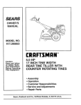
TINE
REPLACEMENT
- To maintain the superb tilling performance of this machine the tines should
,_.CAUTION:
Tines are sharp. Wear
gloves or other protection when handling
tines.
be checked for sharpness, wear, and
bending, particularly the tines which are
next to the transmission,
If the gap
between the tines exceeds 3-1/2 inches
A badly worn tine causes your tiller to work
harder and dig more shallow. Most important, worn tines cannot chop and shred
organic matter as effectively nor bury it as
deeply as good tines. A tine this worn
needs to be replaced.
they should be replaced or straightened
as necessary
" New tines should be assembled. Sharpened tine edges will rotate rearward
from above.
New Tine
J
3-1/2" Max
Counter line
Rotation
_
t
t
}-----
Hairpin Clip
\
Sharp Edg_
Sharp Edge
Shear Pin
Shear Pin
17
Sharp Egde
ENGINE
Maintenance, repair, or reRlacement of the
emission control devices af_d systems,
which are being doqe at the customers
expense, may be p_rformed by any nonroad engine repair establishment
or individual, Warranly repairs must be performed by an authorized engine manufacturer's service outlet,
TO ADJUST
CABLE
THROTTLE
CONTROL
, The throttle control has been preset at
the factory and adjustment should not
be necessary,
if adjustment is necessary, proceed as follows:
o With engine not running, move remote
throttle control lever to "FAST" position+
• If throttle lever on engine touches high
speed stop, no further adjustment is
necessary.
If throttle lever does not
touch high speed stop, continue with
adjustment procedure.
• Loosen cable clamp screw+
, Move throttle lever up until it touches
high speed stop, and hold in this position.
• Tighten
cable clamp _crew securely.
Throttle
High
Speed
Stop
Clamp Screw
Throtti'e
Lever
TO ADJUST
CARBURETOR
The carburetor has been preset at the factory and adjustment should not be necessary+ However, engine performance can
be affected by differences in fuel, tempera+
ture, altitude or load. If the carburetor
does need adjustment, contact your nearest authorized service center/department
IMPORTANT;
never tamper with the
engine governor, which is factory set for
proper engine speed. Overspeeding
the
engine above the factory high speed setting can be dangerous.
!f you think the
engine-governed
high speed needs adjusting, contact your nearest authorized service center!department,
which has the
proper equipment and experience to make
any necessary adjustments.
Immediately prepare your tiller for storage
at the end of the season or if the unit will
not be used for 30 days or more.
,_,CAUTION:
Never store the tiller with
gasoline in the tank inside a building
where fumes may reach an open flame or
spark. Allow the engine to coot before
storing in any enclostJre,
TILLER
• Clean entire tiller (See "CLEANING"
in
the Customer Responsibilities
section of
this manual),
Inspect and replace belts, if necessary
(See belt replacement instructions in the
Service and Adjustments
section of this
manual).
, Lubricate as shown in the Customer
Responsibilities
section of this manual.
o Be sure that all nuts, bolts and screws
are securely fastened.
Inspect moving
parts for damage, breakage and wear
Replace if necessary
• Touch up all rusted or chipped paint surfaces; sand light!y before painting,
,
ENGINE
FUEL SYSTEM
IMPORTANT:
It is important to prevent
gum deposits from forming in essential fuel
system parts such as the carburetor, fuel
filter, fuel hose, or tank during storage.
also, experience indicates that alcohol
blended fuels (called gasohol or using
ethanol or methanol) can attract moisture
which leads to separation and formation of
acids during storage_ Acidic gas can damage the fuel system of an engine while in
storage.
* Drain the fuel tank,
, Start the engine and let it run until the
fuel lines and carburetor are empty
- Never use engine or carburetor cleaner
products in the fuel tank or permanent
damage may occur.
o Use fresh fuel next season.
NOTE: Fuel stabilizer is an acceptable
afternative in minimfzing the formation of
fuel gum deposits during storage. Add stabilizer to gasoline in fuel tank or storage
container° Always follow the mix ratio
found on stabilizer container.
Run engine
at least 10 minutes after adding stabilizer
to allow the stabilizer to reach the carbure _
tor. Do not drain the gas tank and carbu_
retor if using fuel stabilizer
ENGINE
OIL
Drain oil (with engine warm) and replace
with clean oil. (See "ENGINE" in the
Customer Responsibilities
section of this
manual)_
CYLINDER
, Remove spark p_ug.
• Pour I ounce (29 ml) of oil through
spark plug hole into cylinder
,, Pull starter handle slowly severa_ times
to distribute oil
• Replace
with new spark plug
OTHER
,, Do not store gasoline
to another.
from one season
• Replace your gasoline can if your can
starts to rust. Rust and/or dirt in your
gasoline will cause problems
• If possible, store your unit indoors and
cover it to give protection from dust and
dirt_
, Cover your unit with a suitable protective
cover that does not retain moisture.
Do
not use plastic. Plastic cannot breathe
which allows condensation
to form and
wiIl cause your unit to rust
IMPORTANT:
Never cover tiller while
engine and exhaust
areas are still warm
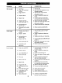
CORRECTION
CAUSE
PROBLEM
.,=
Wt}I not start
1, Fil_fuel tank_
2. See "TO START ENGINE" tn,,the
Operation section,,
3. Walt several minutes betore
1., Out of fuel
2. Engine not "CHOKED"
properly
3 Engine flooded.
4
attempting to start.
4. Clean or replace air cleaner car
tridge°
5, Drain fuel tank and carburetor,
and refill tank with fresh gasoline.
6. Remove fuel tank and clean.
Dirtyair cleaner
5. Water in fuel
6 Clogged fuel tank.
7. Loose spark plug wire.
7. Make sure spark plug wire is seat
ed properly on plug.
8. Replace spark plug or adjust gap.
8
Bad spark plug or
improper gap
9. Carburetor out of adjustment.
9
Make necessary adjustments.
, ,, ,,,,,,
Hard to start
1. Throttle control not set
2
position_
2, Clean or replace air cleaner car
tridge.
3. Replace spark plug or adjust gap.
properly_
Dirtyair cleaner.
3. Bad spark ptug or
improper gap.
4. Stale or dirty fuel.
5
1. Place throttle control in "FAST"
4, Drain fuel tank and refill with fresh
Loose spark plug wire
6. Carburetor out of •
gasoline.
:
5. Make sure spark plug wire is seat
ed properly _n plug.,
6 Make necessary adjustments,
adjuslment.
,,
Loss of power
1. Engine is overloaded.
2. Dirty air cleaner.
3
4
Low oil level/dirly oil.
Faulty spark plug.
5 Oil intuel
6 Stale or dirty fuel.
7. Water in fuel.
8. Clogged fue! tank.
9. Spark plug wire loose.
wire,
10, Dirty engine air screen.
1I, Dirty/clogged muffler.
12. Carburetor out of
adjustment.
13, Poor compression.
,-ii
LLLJU_.'II I 'l '
'= I I'l
1. Set depth stake and wheels for
shallower tilling.
2. Clean or replace air cleaner car
tridge.
3. Check oil level/change oil.
4. Clean and regap or change spark
plug.
5. Drain and clean fuel tank and
refill, and clean carburetor,
6. Drain fuel tank and refill with fresh
gasoline,
7. Drain fuel tank and carburetor,
and refill tank with [resh gasoline.
8. Remove fuel tank and clean.
& Connect and tighten spark plug
10. Clean engine airscreen.
tl. Clean/replace muffler.
12. Make necessary adjustments°
13. Contact an authorized Sears
Service CenteriDeparlment,
2O
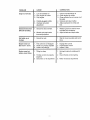
PROBLEM
=
CAUSE
, CORRECTION
,
Engine overheats
1., Low oil level/dirty oil
2., Dirty engine air screen,
3, Dirty engine,
4. Partially plugged muffler.
5, Improper carburetor
adjustment,
Excessive bounce/
5. Adjust carburetor to richer posi
tion.,
1. Ground too dry and hard.,
1, Moisten ground or wait for more
favorable soil conditions.
2. Wheels and depth stake
incorrectly adjusted
2
difficult handling
Soil balls up or
clumps
1., check oil level/change oil,
2 Clean engine air screen,
3. Clean cylinder fins, air screen, muf
tier area,
4. Remove and clean muffler.
Adjust wheels and depth stake.
Wait for more favorable soil condi
lions.
1. Ground too wet.
i
Engine runs but
tiller won't move
1. Tine control is nol engaged2. V-belt not correctly adjusted
3,, V-belt is off pulley(s)
Engine runs but
tabors when tilling
I
Tilling too deep,
2. Throttle control not properly
adjusted,
3. Carburetor out of adjustment.
i
r
,i
Engage tine control
Inspect/adjust V-belt
3. Inspecl V.belt,
2,,
1. Set depth stake for shallower tii]
ing.
2, Check throttle control setting
3_ Make necessary adjustments
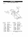
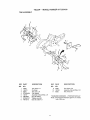
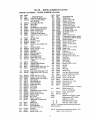
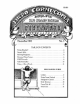
TILLER
- - MODEL
NUMBER
917.293400
HANDLES
9
2
1\
'_,
%,
"tt.
",X
29
tl
\
KEY
PART
NO.
NO.
1
2
3
4
5
6
7
8
9
10
11
12
13
14
15
16
17
127o12x
141406
110673X
127254X
6712J
137119
1t0641X
71191008
72010520
110646X
STD624003
81328
110741;4
109313X
110702X
STD533710
109229X
KEY
NO.
DESCRIPTION
Tflrollle, Control
Grip, Handle
G[ommet, Handle
Bar, Drive Conlrol Assembly
Cap, Vinyl
Panel, Conlrol
Bushing, Spill
"Screw, Pan Head #10-24
°Bolt,5/16-18 x 2-112
Handle, Grip
'Clip, Hairpin
Bolt, Shoulder
Handle, Shift
Grommet, Rubber
Rod, Shill
"Boll, Carriage 3/8-16 x t Gr, 5
t.eck, Handle
PART
NO.
DESCRIPTION
18
19
20
21
22
23
STD541437
19131611
109228X
150258
121145X
86777
24
25
26
27
28
29
31
9484R
73970500
110675)(
STD541025
STD551125
STD541462
150696
*Nut, Cenlefiock 318_16
Washer 13/32 x 1 × 1t Ga
Lever. Lock. Handle
Handle, Assemble
Clip, Ptasllc, Cable
Screw, He×, Washer Hd, Slotted
#10-24 x 1/2
Clip
Locknut, Hex, Flange
Clutch, Cable
*Nut, Hex 114-20
'Washer, Lock 1/4
"Nut, Keps #10.24
Boll, Pivol
* STANDARD HARDWARE - - PURCHASE LOCALLY
NOTE: All component dimensions given in US. laches
1 inch = 25,4 mm
22
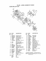
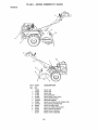
TILLER
- - MODEL
NUMBER
917.293400
MAINFRAME, LEFT SIDE
7
3
KEY
PART
NO,
NO.
1
2
3
4
5
6
7
STD541431
STD551137
STD541037
74930568
154734
1t011tX
STD532505
8
9
8700J
86777
10
11
12
13
14
9484R
STD551125
STD541025
23230506
120938X
15
16
17
19
2O
21
STD551031
145102
STD541031
12000028
110653X
145216
22
23
104214X
5015J
128952
795R
DESCRIPTION
Nut, Keps 5/16-18
*Washer, Lock 8/8
"Nut, Hex 3/8.t6
Bratt,Hex 5/16-18x4-114
Screw Shift Lever
Lever, Shift
*Bert,Carriage 1/4-20 x 1/2
Gr. 5
Plate, Shiftlndicator
Screw. Hex, Washer Head,
Stetted #10_24 x 1/2
Clip
'Washer, Lock 1/4
'Nut, Hex 1/4-20
*Screw, Set, 5/16.18 x 3/8
Spacer, Split 0327 x 0.42
x 2..68
'Washer 11f32 x 11/16 x 16 Ga.
Sheave, Transmission
*Nut, Hex 5/16-18
R_ng,Retainer
Guard, Pinch Point
Spacer, Split 0 327 x 0 42
xl 688
Nut, Cap 5/16-18
T_re
Rim
Tire Valve
"o +"
KEY
PART
NO.
NO.
24
25
26
27
28
29
30
31
32
83
34
35
36
37
88
39
41
42
43
44
9
I26875X
8TD624003
131t59X574
132801
104679X
12000032
159229
102384X
102141X
STD523710
102383X
74760532
102331X
130812
145822
140062
19111610
151004
69180
164173
DESCRIPTION
Rivet, Orllled
'Clip, Hairpin
Guard, Bell
Belt, V
Pulley, td]er
Ring, Klip
Bracket. Idler
Boff, I'-tex 5/16-16 x 12
Shaft, tdler Arm
"Bolt, Hex 3/8-16 x I
Counterweight, LH
Botl, Hex 5/16q8x 1 1/2
8racket, Reinforcement, L H
Sheave, Engine
Slud, Guard Boil
Cap, Plunger
Washer 11t32 x 1 x 10 Ga
Spacer
Nut Lock #1@24
Belt Keeper
"STANDARD HARDWARE - - PURCHASE LOCALLY
NOTE: Aft component dimensions given in U S. inches
1 inch= 25 4 mm
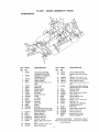
I ILLP-..H - - MUUP_L
MAINFRAME,
NUNtUI:.H
_ 1/.Z_UU
RIGHT SIDE
/
13
12
\
9
10
KEY
NO.
1
2
3
4
5
6
7
8
9
10
PART
NO.
KEY
NO.
DESCRIPTION
11
12
t3
157976
73970500
Bumper
Locknut, Hex, Flange 5/1618
STD55I 031 'Washer I1/32 x 11/16 x 16
Ga.
74760512
BoIt, Hex 5/16-18 x 3/4
102332X
Bracket, Reinforcement
74760532
Bolt, Hex 5/16-18 x 2
I02173X
Counter Weight, R H.
STD551137 *Washer, Lock 3/8
STD541037 "Nut, Hex 3/8-16
7476O524
Bolt, Hex 5/16-18 x 1-1/2
t4
15
PART
NO.
DESCRIPTION
STD624003
126875X
5015J
128952
795R
STD541431
......
*Clip, Hairpin
Rivet, Drilled
Tire
Rim
Tire Valve
*Nut, Keps 5/16-18
Engtne, (See Breakdown)
Craftsman Model No.
I43.976001
STANDARD
HARDWARE
- _,PURCHASE
LOCALLY
NOTE: All componentd{mensionsgiven_nUSinches,
t inch = 254 ram
24
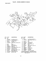
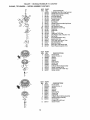
TILLER
- - MODEL
NUMBER
9!7,293400
TRANSMISSION
48
25
KEY
PART
NO.
NO,
t
154354
150698
3 106211X
,4 5020J
5 1370H
6
7
8
9
10
1!
12
t3
I4
t5
t6
18
t9
20
137335
145101
4895H
154467
7392M
100371K
106160X
142145
8353J
'12000039
154466
4358J
12000040
102114X
21
22
23
24
25
27
I02t15X
6803J
102111X
STD551143
STD541143
143009
28
29
I_390X
1_1_X
DESCRIPTION
Transmission Assembly
(Includes Key Nos. 2-52)
Gearcase, L H. w/Bearing
(fncludes Key No 4}
Gasket, Gearcase
Beadng, Needle
Washer, Thrusl 5/8 x I 10 x
1i32
Pinion, Input
Shaft, Input
Bearing, Needte
Washer, Seal
Ball, Sleel
Spring, Shift, Fork
O,Ring
Arm, Shill
Fork, Shift
Ring, Kltp
Shaft, Shift
Washer
Ring, Kiip
Gear,Assembly, Reverse Idler
(Includes Key Nos. 21 and 22)
Gear, Reverse Idler
Bearing, Needle
Shaft, Reverse Idler
"Washer, Lock 7/t6
*Nul, Hex 7/16..20
Bearing, Shaft, Ground Orive
LH,
Spacer 0765 × ! .125 x 1 23
Chain #35-50 Pitch
KEY
PART
NO,
NO.
DESCRIPTION
30
150737
Ground
31
143008
Bearing,
RH.
32
106388X
Spacer
33
34
35
102121X
102112X
102101X
Sp[ocket and Gear Assembly
Shaft, Reduction (2nd)
ScreW, Whiz. Lock 5/16-18 x 31/2
36
154355
Sprocket Assembly w/Bearing
(Includes Key Nos 37 and 38)
37
4422J
Bearing,
38
39
40
154356
!05345X
105346X
Sprockel, Title
Gear,Ctusler,
Red 1st & 2nd
Gear, Reverse
41
42
8358J
4220R
Shaft, Reduction
Washer, Thrust
43
44
106146X
!55236
Spacer 1 01 x 175 x 0760
SealAsm,
OII
48
150700
49
132688
Gearcase, RH w/Bearing
(Includes Key No, 8)
Shaft, _ne
50
51
106147X
17720408
Chain,
Screw
52
73220500
"Nut, He×
53
-_
122204X
6066J
Beating
Grease,
' SIANDARD
NOTE:
HARDWARE-
Shatt Assembly
Shaft, Ground Drive
070x
1 O0 x 1 150
Needle
(1st)
Roller //50-50 Pitch
1/4-20 x 1/2
5/16,18
Kit, Tfne Shaft
Plaslilube #1
- PURCHASE
All componenl dimensions
I inch = 25.4 mm
L,OCALLY
given in U S inches
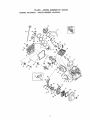
TILLER
- - MODEL
NUMBER
917.293400
TINE SHIELD
24
2¢
29
f9
KEY
PART
NO.
NO.
1
2
3
4
5
98000129
16t415X574
8393./
120(}0036
ST6533107
6
7
8
9
10
tl
12
13
14
15
16
839,M
8392J
'_09230X
124289X574
STD5331 t 0
ST6541031
STD551131
721t0510
124311X
16t414X574
73510400
DESCRIPTION
KEY
NO.
Nut, Range 5/16d8
Shield,Side, Outer L.H.
Pin,Stake, Oeplh
Ring, Klip
*Bet•,Cardage 5/16-18 ×3/4 Gr
5
Spring
Bracket, Latci_
Spring, Depth Stake
Shte_d,Tine
*Bolt,Carriage 5/16-16 x I Gr 5
*Nut, Hex 5/16q8
'Washer, Lock 5/16
Bolt, Carriage 5/16-18 x 1-1/4
Bracket, Shield '[ine
Shield, Side, Outer RH
Nut, Hex "_/4-20
26
17
18
PART
NO,
DESCRIPTION
162175
STD532512
NuL Wing Forged 5/16o18
*Boll, Carriage 1,'4-20 x I-1/4
Gr. 5
G_p
19
102701X
*Nul, Hex 3/0-10
20
STD541037
21
102"f56X
Stake, Depth
Boll, Hex 318-16 x2
22
74930632
Hinge
23
4440J
"Bolt, Carriage 1/4.20 x 1/4
24
72140404
25 6712J
Cap, Vinyl
Pad, Idler
26
109227X
27
t02695X574
Shield, LeveEing
26
126588X
Pin, Hinge
Shield,
Side
29
124309X574
30
73970500
Locknut,He×,Flange
* STANDARD HARDWARE - - PURCHASE LOCALLY
NOTE; All component dimensions given in US _nches
i inch = 25,4 mm
TILLER
- - MODEL NUMBER
9t 7.293400
TINE ASSEMBLY
2
I
1
9
KEY
PART
NO.
NO,
1
4459J
2
132673
3
4
6
6554J
STD624008
132727
6
73610600
7
8
STD551137
74610616
DESCRIPTION
Tine, Outer, LH
Pin, Shear
'_qne,Inner, L H
"Clip. Hairpin
Assembly, Hub and Plale, L H
Nut, Hex 3/8.24
*Washer, Lock 3/8
Bolt, Hex 3/8-24 x I
KEY
PAR3 r
NO.
NO.
9
10
11
4460J
132728
6555J
" STANDARD
NOTE;
DESCRIPTION
"line, Outer, R H
Assembly. Hub and Pfate. R H
3qne. Inner, R H
HARDWARE
-. PURCHASE
All componenl dimensions
t inch = 25 4 mm
LOCALLY
given in U S inches
TILLER
--. MODEL
NUMBER
917.293400
DECALS
10
12
KEY
PAR]'
NO.
NO.
t
2
3
4
5
6
7
8
9
t0
1!
12
-_
•,-
158095
145023
157982
157983
137536
120431X
102180X
157984
120075X
163094
162215
164527
163160
163161
DESCRIPTION
Decal, Lago
Decal, Logo
Decal, Logo
Decal, Description
Decal, Caution, Ddve Controt
Decal, Hand Placement
Decal, Shift Indicator
Decal, "Fine,Shield, Counter Rotating Tines
Decal, Warning, Rotaling _nes
Decal, "lqneDeplh Stake
Decal, Tine, Shield, Warning Dom
Decal, OpariLub lnst_ctfons
Manual, Owner's {English]
Manual, Owner's (Spanish)
28
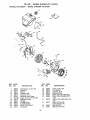
TILLER
- - MODEL NUMBER
9t7.293400
ENGINE, TECUMSEH - - MODEL NUMBER 143,976001
TILLER
ENGINE,
TECUMSEH
- - MODEL
- - MODEL
NUMBER
NUMBER
917,293400
143.976001
370&
¢
KEY
NO.
PART
NO.
1
2
14
15
16
t7
!8
lg
20
25
25A
26
30
36866
26727
28277
30589
36618
36700
65t028
36710
32600
36621
36622
30200
34740
KEY PART
NO. NO.
DESCRIPTION
Cylinder (tnoL 2, 20 & 72)
Dowel Pin
Washer
Governor Rod
Governor Lever
Governor Lever Ciamp
Screw, Torx "1"-15,8-32 x 3/8"
Extension Spring
Oil Seal
Air Baffle (Left)
A_r Baffle (Right)
Screw, 10-24 x 9/16"
Crankshaft
30
DESCRIPTION
35
36
37
38
40
40
29826
29918
29216
29642
40004
40005
Screw, 10-32 x 3/4"
Lock Washer
Lock Nut, 10-32
Retaining Ring
Piston, Pin & Ring Set (Std.)
Piston, Pin & Ring Se{ (.010"
41
36070
41
36071
42
42
40006
40007
Piston & Pin AssOy (Std) (IncL
43)
Piston & Pin Ass0y
('.0i0" OS) _JrtcL43)
Ring Set (St&!,'
Ring Set (.010 OS)
os)
TILLER
- - MODEL
NUMBER
9t7.293400
ENGINE, TECUMSEH - - MODEL NUMBER 143.976001
KEY
NO.
43
45
PART
NO.
2038t
32875A
46
48
49
50
60
64
65
69
70
32610A
35616
36611
36620
36623
650738
30200
36624
36625
72
75
80
81
82
27642
27897
30574A
30590A
30591
83
86
89
90
92
93
100
101
103
36057
650488
610961
611205
650815
6508 !6
34443A
610118
651007
110
119
120
125
125
36054
36719
36721
36471
36472
126
126
29314B
29315C
130
130A
135
150
151
153
154
155
157
158
159
I60
t6I
t73
178
182
184
650912
650999
34645
31672
31673
36649
650913
35624A
650914
36629
35626
36630A
651008
36675A
650852
650451
26756
185
186
200
36631
36711
36736
206
207
209
610973
36632
650821
DESCRIPTION
Piston Pin Retaining _Ring
Connecting Rod AssOy
(Incl. 46 & 49)
Connecting Rod Bolt
Valve Lifter
Oil Dipper
Camshaft (Incl 253 & 254)
Blower Housing Extension
Screw, 1/4-20 x 5/8"
Screw, 10-24 x 9/16"
*Cylinder Cover Gasket
Cylinder Cover (IncL 75 thru
83_)
OII Drain Plug
Oil Seal
Governor Shaft
Washer
Governor Gear AssOy (Incl.
81 )
Governor Spool
Screw, 1/4-20 x 1-1/4"
F_ywhee!Key
Flywheel
BellevilIe Washer
Flywheel Nut
Solid State Ignition
Spark Plug Cover
Screw, Torx T-15, 10-24 x
15/16"
Ground Wire
*Cy{inder Head Gasket
Cy{inder Head
Exhaust Valve (Std.) (Incl. 15 !)
Exhaust Valve (1/32' OS)
(incl. 151)
Intake Valve (Std.) (Incl 151)
Intake Valve (1/32" OS) (tnd.
151)
Screw, 5/16-18 x 1-1/2"
Screw, 5/16-18 x 2-.41/64"
Resistor Spark Plug (RN4C)
Valve Spring
Valve Spring Cap
Push Rod Guide
RockerArmSlud
RockerArm
Nut, 1/4-28
Push Rod
*Rocker Arm Cover Gasket
Rocker Arm Cover
Screw, 1/4-20 x 31/64"
Breather Tube
Nut, 1/4-20
Screw, 1/4-20 x 1"
*Carburetor To Intake Pipe
Gasket
Intake Pipe
Governor Link
Control Bracket
(Incl. 206, 210 & 211)
Terminal
Throtlle Link
Screw, 10_32 x 1/2"
KEY
NO.
210
211
223
224
238
239
240
245
245A
250
25t
252
253
254
260
261
261A
262
275
277
285
287
290
292
298
300
301
305
307
308
309
310
PART
NO.
27793
28942
650451
36581
28820
27272A
36633
36046
36634
36635A
650886
650821
36701
36702
36992
651008
650821
651008
36759
650988
35985B
651008
30705
26460
650665
36875
36246
36877
35499
36651
651011
36878
313
325
34080
29443
327
340
34t
342
35392
36876
36644
651010
342A
370A
380
390
400
650738
36261
640025
590704
36720
416
36085
417
600
900t_
650760
65!013
9001_1
DESCRIPTION
Conduit Clip
Screw, 10-32 x 3/8"
Screw, 1/4-20 x 1"
*Intake Pipe Gasket
Screw, 10-.32 x 1/2"
*Air Cleaner Gasket
Air Cleaner Body (Inct 239)
Air Cleaner Filter
Air Cleaner Filter (Poly)
Air Cleaner Cover
Wing Nut
Screw, 10-32 x 1/2"
Compression Release Weight
Compression Release Spring
Blower Housing
Screw, 1/4-20 x 31/64"
Screw, 10-32 x 1/2"
Screw, 1t4.20 x 31/64'*
Muffler
Screw, 114-20 x 2-9/32"
Starter Cup
Rivet, t/4-20 x 31/64"
Fuel Line
Fuel Line Clamp
Screw, 1/4_15 x 3/4"
Fuel Tank (lncl 292 & 301)
Fuel Cap
011Eili Tube
000 Ring
Fill Tube Clip
Screw, 10-32 x 15/16"
Dipstick
Spacer
Wire Clip
Starter Plug
Fue! Tank Bracket (Upper)
Fuel Tank Bracket (Lower)
Screw, 1/4-20 x 7/8"
Screw, 1/4-20 x 5/8"
Lubrication Decal
Carburetor' (tncl, !84)
Rewind Starter
Gasket Set
(tnd llems Marked' in Notes)
Spark Arrestor Kit
(inct, 417) (Oplional)
Screw, 8-32 x 3/8'_
Washer
Replacement Engine - None
Replacement S/B 754295,
order from 71-999
I_ I_
RPM High 3050 to 3350
N
I_
RPM Low 1650 to 1950
(NOTE: This engine could have been built with
590746 starter)
NOTE: Al! component dimensions given in US
inches 1 inch = 25 4 mm
T|LLEH
ENGINE,
TECUMSEH
- - ML)IJr_L
- - MODEL
NUIVI_I::::H f91 [.Z_J;SqUU
NUMBER
143.976001
NO,
....
KEY
1
2
4
5
6
7
16
17
16
20
20A
25
27
26
29
30
NO.
640025
PART
631615
631767
631184
631183
631036
650506
632164
650417
630766
640018
640053
631867
631024
632019
631028
631021
3!
35
36
631O22
36045
640019
[_,_i
40
37
44
640015
632547
27110
__._
_.._
47
48
630748
631027
KEY
PART
"'
'
_!_,,_
_l
_
6-_
l "_
_- 2,
NO.
1
2
3
4
5
6
7
8
tl
12
13
KEY
NO.
32
NO.
590736
590599A
590600
590696
590601
59O697
590698
590699
5907OO
590705
590535
590701
DESCRIPTION
Carburetor (Ind 184 or Eng Parts fist)
Thtotlle Shaft & Lever Assembly
Throttle Return Spdng
Dust Seal Washer
Dusl Seat (Throttle)
Throtlle Shutter
Shutter Screw
Fuel Fitting
Throl_le Crack Screw/Idle Spd Screw
Tenston Spdng
tdle Restrictor Screw
Idle Reslrlctor Screw Cap
Float Bowl
Float Shaft
Float
Float Bowl ()00 Ring
Inlet Needle, Seat, & Clip (Incl. 31)
Spring Clip
Primer Bulb!Retainer Rtog
Main Nozzle Tube
000 Rtng, Main Nozzle Tuba
High Speed Bowl Nut
Bowl Nul Washer
Welch Plug, Idle Mixture Welt
Welch Plug, Atmosphe6c Venl
DESCRIPTION
Recoil Starter
Sprlng Ptn (tncl 4)
Washer
Retainer
Washer
Brake Spr_ng
StaMer Dog
Dog Spring
Pulley & Rewind Spring AssOy.
Starter Hopstng AssOy,
Starter Rope ( 98" X 9/64" d_a)
Starter Handle
PART
NO.
1
2
3
4
5
6
7
8
11
12
590748
590599A
590600
590679
590601
590678
590680
590412
590681
590747
590535
13
590701
DESCRIPTION
Recoil Starter
Spring Pin (Incl 4)
Washer
Retainer
Washer
Brake Spring
Starter Dog
Dog Spdng
Pulley & Rewind Spdng Assembly
Slader Housing Assembly
Stader Rope
(Length 98" × 9164,"die.)
Stader Handle
34
For the repair or replacement pads you need
deli_'ered directly to your home
Call 7 am - 7 pro, 7 days a week
1-800-366-PART
(1-800-366-7278)
Para ordenar
piezas con entrega
domicilio
- 1-800-659-7084
a
For in-house major brand repair service
Call 24 hours a day, 7 days a week
1-800-4-REPAIR
(1-800_473_7274)
Para pedir servicto de reparaci6n
domicilio
- 1-800-676-5811
a
For the locat}on of a Sears Parts and
Repair Center in your area
Call 24 hours a day, 7 days a week
1-800-488-1222
,.-,,,ml
_luiim
For information on purchasing a Sears
Maintenance Agreement or to inquire
about an existing Agreement
Call 9 am - 5 pro, Monday-Saturday
1-800-827-6655
When requesting service or ordering
pads, always provide the following
information:
° Product Type
° Model Number
• Part Number
• Part Description
Amenca_s Repair Specialrsts
163160
Rev, 9
2.12,98TR
Printed
in U.S.A.