1
."
q
D ",'
.
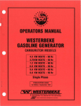
OPERATORS MANUAL
W-70GA MARINE
GASOLINE
INE
FIRST EDITION
MARCH 2004
~r~ rWESTERBEKE
J
WESTERBEKE CORPORATION • 150 JOHN HANCOCK ROAD
• MYLES STANDISH INDUSTRIAL PARK· TAUNTON MA 02780
WEB SITE: WWW.WESTERBEKE.COM
-.......
A'A'A'A'
NMMA Member National Marine Manufacturers Association
A
WARNING
Exhaust gasses contain Carbon Monoxide, an odorless and
colorless gas. Carbon Monoxide is poisonous and can cause
unconsciousness and death. Symptoms of Carbon Monoxide
exposure can include:
-Dizziness
- Throbbing in Temples
-Nausea
- Muscular Twitching
-Headache
- Vomiting
- Weakness and Sleepiness -Inability to Think Coherently
IF YOU OR ANYONE ELSE EXPERIENCE ANY OF THESE SYMPTOMS,
GET OUT INTO THE FRESH AIR IMMEDIATELY. If symptoms persist,
seek medical attention. Shut down the unit and do not restart
until it has been inspected and repaired.
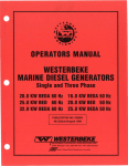
WARNING
A WARNING DECAL is provided by
WESTERBEKE and should be fixed to a
bulkhead near your engine or generator.
WESTERBEKE also recommends installing
CARBON MONOXIDE DETECTORS in the
living/sleeping quarters of your vessel.
They are inexpensive and easily
obtainable at your local marine store.
Generators Produce CARBON MONOXIDE
Regular Maintenance Required
l5i5fJWESTERBEKE
Engl"...a...ttn
CALIFORNIA
PROPOSITION 65 WARNING
Marine diesel and gasoline engine
exhaust and some of its constituents
are known to the State of California
to cause cancer, birth defects,
and other reproductive harm.
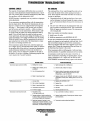
SAFETY INSTRUCTIONS
INTRODUCTION
PREVENT BURNS - FIRE
Read this safety manual carefully. Most accidents are
caused by failure to follow fundamental rules and
precautions. Know when dangerous conditions exist and
toke the necessary precautions to protect yourself, your
personne~ and your machinery.
The following safety instructions are in compliance with
the American Boat and Yacht Council (ABYC) standards.
•
PREVENT ELECTRIC SHOCK
•
A WARNING: Do not touch AC electrical connectiollS
while engine is running, Dr when connected to shore
power. Lethal voltage is present at these connections!
Do not operate this machinery without electrical
enclosures and covers in place.
• Shut off electrical power before accessing electrical
equipment.
• Use insulated mats whenever working on electrical
equipment.
• Make sure your clothing and skin are dry, not damp
(particularly shoes) when handling electrical equipment.
• Remove wristwatch and all jewelry when working on
electrical equipment.
• Do not connect utility shore power to vessels AC
circuits, except through a ship-to-shore double throw
transfer switch. Damage to vessels AC generator may
result if this procedure is not followed.
• Electrical shock results from handling a charged capacitor. Discharge capacitor by shorting terminals together.
A WARNING: Fire.can cause injury Dr death!
•
•
•
PREVENT BURNS - HOT ENGINE
A WARNING: Do not touch hot engine parts Dr
exhaust system components. A running engine gets
very hot!
•
Always check the engine coolant level at the coolant
recovery tank.
A WARNING: Steam can cause injury Dr death!
•
In case of an engine overheat, allow the engine to cool
before touching the engine or checking the coolant.
•
Prevent flash fires. Do not smoke or permit flames or
sparks to occur near the. carburetor, fuel line, filter, fuel
pump, or other potential sources of spilled fuel or fuel
vapors. Use a suitable container to catch all fuel when
removing the fuel line, carburetor, or fuel filters.
Do not operate with a Coast Guard Approved flame
arrester removed. Backfire can cause severe injury or
death.
Do not operate with the air cleaner/silencer removed.
Backfire can cause severe injury or death.
Do not smoke or permit flames or sparks to occur near
the fuel system. Keep the compartment and the
engine/generator clean and free of debris to minimize the
chances of fire. Wipe up all spilled fuel and engine oil.
Be aware - diesel fuel will burn.
PREVENT BURNS - EXPLOSION
A WARNING: Explosions from fuel vapors can cause
injury Dr death!
•
Follow re-fueling safety instructions. Keep the vessels
hatches closed when fueling. Open and ventilate cabin
after fueling. Check below for fumes/vapor before
running the blower. Run the blower for four minutes
before starting your engine.
• All fuel vapors are highly explosive. Use extreme care
when handling and storing fuels. Store fuel in a wellventilated area away from spark-producing equipment
and out of the reach of children.
• Do not fill the fuel tank(s) while the engine is running.
• Shut off the fuel service valve at the engine when servicing
the fuel system. Take care in catching any fuel that might
spill. DO NOT allow any smoking, open flames, or other
sources of fire near the fuel system or engine when servicing. Ensure proper ventilation exists when servicing the
fuel system.
• Do not alter or modify the fuel system.
• Be sure all fuel supplies have a positive shutoff valve.
• Be certain fuel line fittings are adequately tightened and
free of leaks.
• Make sure a fire extinguisher is installed nearby and is
properly maintained. Be familiar with its proper use.
Extinguishers rated ABC by the NFPA are appropriate
for all applications encountered in this environment.
Engines & Generators
SAFETY INSTRUCTIONS
ACCIDENTAL STARTING
TOXIC EXHAUST GASES
A WARNING: Accidental starting can cause injury
A WARNING: Carbon monoxide (CO) is a deadly gas!
or death!
•
Ensure that the exhaust system is adequate to expel gases
discharged from the engine. Check the exhaust system
regularly for leaks and make sure the exhaust
manifolds/water-injected elbow is securely attached.
Make certain all personnel are clear of the engine before
starting.
•
Be sure the unit and its surroundings are well ventilated.
Run blowers when running the generator set or engine.
Make certain all covers, guards, and hatches are
re-installed before starting the engine.
•
Do not run the generator set or engine unless the boat is
equipped with a functioning marine carbon monoxide
detector that complies with ABYCA-24. Consult your
boat builder or dealer for installation of approved
detectors.
•
For additional infonpation refer to ABYC T-22
(educational information on Carbon Monoxide).
•
Disconnect the battery cables before servicing the engine/
generator. Remove the negative lead first and reconnect
it last.
•
•
BATTERY EXPLOSION
A WARNING: Battery explosion can cause injury
or death!
•
•
Do not smoke or allow an open flame near the battery
being serviced. Lead acid batteries emit hydrogen, a
highly explosive gas, which can be ignited by electrical
arcing or by lit tobacco products. Shut off all electrical
equipment in the vicinity to prevent electrical arcing
during servicing.
A WARNING: Carbon monoxide (CO) is an invisible
odorless gas. Inhalation produces flu-like symptoms,
nausea or death!
Never connect the negative (-) battery cable to the
positive (+) connection terminal of the starter solenoid.
Do not test the battery condition by shorting the terminals
together. Sparks could ignite battery gases or fuel vapors.
Ventilate any compartment containing batteries to prevent
accumulation of explosive gases. To avoid sparks, do not
disturb the battery charger connections while the battery
is being charged.
•
Avoid contacting the terminals with tools, etc., to prevent
bums or sparks that could cause an explosion. Remove
wristwatch, rings, and any other jewelry before handling
the battery.
•
Always turn the battery charger off before disconnecting
the battery connections. Remove the negative lead first
and reconnect it last when disconnecting the battery.
•
Do not use copper tubing in diesel exhaust systems. Diesel
fumes can rapidly destroy copper tubing in exhaust
systems. Exhaust sulfur causes rapid deterioration of
copper tubing resulting in exhaust/water leakage.
•
Do not install exhaust outlet where exhaust can be drawn
through portholes, vents, or air conditioners. If the engine
exhaust discharge outlet is near the waterline, water could
enter the exhaust discharge outlet and close or restrict the
flow of exhaust. Avoid overloading the craft.
•
Although diesel engine exhaust gases are not as toxic as
exhaust fumes from gasoline engines, carbon monoxide
gas is present in diesel exhaust fumes. Some of the
symptoms or signs of carbon monoxide inhalation or
poisoning are:
BATTERY ACID
A WARNING: Sulfuric acid in batteries can cause
Inability to think coherently
Dizziness
Throbbing in temples
Headache
Muscular twitching
Nausea
Weakness and sleepiness
AVOID MOVING PARTS
severe injury or death!
•
Vomiting
A WARNING: Rotating parts can cause injury
When servicing the battery or checking the electrolyte
level, wear rubber gloves, a rubber apron, and eye
protection. Batteries contain sulfuric acid which is
destructive. If it comes in contact with your skin, wash it
off at once with water. Acid may splash on the skin or
into the eyes inadvertently when removing electrolyte
caps.
or death!
•
Do not service the engine while it is running. If a
situation arises in which it is absolutely necessary to
make operating adjustments, use extreme care to avoid
touching moving parts and hot exhaust system
components.
Engines & Generators
U
SAFETY INSTRUCTIONS
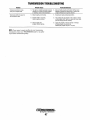
ABYC, NFPA AND USCG PUBLICATIONS FOR
INSTALLING DIESEL ENGINES
•
Do not wear loose clothing or jewelry when servicing
equipment; tie back long hair and avoid wearing loose
jackets, shirts, sleeves, rings, necklaces or bracelets that
could be caught in moving parts.
• Make sure all attaching hardware is properly tightened.
Keep protective shields and guards in their respective
places at all times.
• Do not check fluid levels or the drive belts tension while
the engine is operating.
• Stay clear of the drive shaft and the transmission coupling
when the engine is running; hair and clothing can easily
be caught in these rotating parts.
Read the following ABYC, NFPA and USCG publications
for safety codes and standards. Follow their
recommendations when installing your engine.
ABYC (American Boat and Yacht Council)
"Safety Standards for Small Craft"
Order from:
ABYC
3069 Solomon's Island Rd.
Edgewater, MD 21037
NFPA (National Fire Protection Association)
"Fire Protection Standard for Motor Craft"
Order from:
NFPA
11 Tracy Drive
Avon Industrial Park
Avon, MA 02322
USCG (United States Coast Guard)
"USCG 33CFR183"
Order from:
U.S. Government Printing Office
Washington, D.C. 20404
HAZARDOUS NOISE
A WARNING: High noise levels can cause hearing
loss!
•
•
Never operate an engine without its muffler installed.
Do not run an engine with the air intake (silencer)
removed.
• Do not run engines for long periods with their enclosures
open.
A WARNING: Do not work on machinery when you are
mentally or physically incapacitated by fatigue!
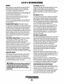
OPERATORS MANUAL
Many of the preceding safety tips and warnings are repeated
in your Operators Manual along with other cautions and
notes to highlight critical information. Read your manual
carefully, maintain your equipment, and follow all safety
procedures.
GASOLINE ENGINE AND GENERATOR INSTALLATIONS
Preparations to install an engine should begin with a
thorough examination of the American Boat and Yacht
Council's (ABYC) standards. These standards are a
combination of sources including the USCG and the NFPA.
Sections of the ABYC standards of particular interest are:
H-2 Ventilation
P-l Exhaust Systems
P-4 Inboard Engines
E-9 DC Electrical Systems
All installations must comply with the Federal Code of
Regulations (FCR).
Engines & Generators
iii
INSTALLATION
When installing WESTERBEKE engines and generators it is important that strict
attention be paid to the following information:
CODES AND REGULATIONS
Strict federal regulations, ABYC guidelines, and safety codes must be complied with
when installing engines and generators in a marine environment.
SIPHON-BREAK
For installations where the exhaust manifold/water injected exhaust elbow is close to
or will be below the vessel's waterline when the vessel is static or under various
operating conditions, provisions must be made to install a siphon-break in the raw
water supply hose to the exhaust elbow. This hose must be looped a minimum of 24"
above the vessel's waterline. Failure to use a siphon-break when the exhaust manifold injection port is at or below the load waterline will result in raw water damage
to the engine and possible flooding of the boat.
If you have any doubt about the position of the water-injected exhaust elbow relative
to the vessel's waterline under the vessel's various operating conditions, install a
siphon-break.
NOTE: A siphon-break requires periodic inspection and cleaning to ensure proper
operation. Failure to properly maintain a siphon-break can result in catastrophic
engine damage. Consult the siphon-break manufacturer for proper maintenance.
EXHAUST SYSTEM
The exhaust hose must be certified for marine use. The system must be designed to
prevent water from entering the exhaust under any sea conditions and at any angle
of the vessels hull.
Adetailed 40 page Marine Installation Manual covering gasoline and
diesel, engines and generators, is available from your WESTERBEKE
dealer.
Engines & Generators
iv
AVAILABLE FROM
YOUR WESTERBEKE
DEALER
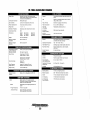
TABLE OF CONTENTS
Parts Identification .............................................2
Introduction .........................................................3
Fuel, Engine Oil, and Engine Coolant...~ ............. 5
Instrument Panel .................................................6
Preparations for Initial Start-Up .........................7
Starting/Stopping Procedure ............................... 8
Engine Break-in Procedure .................................9
The Daily Operation ........................................... 10
Alarms and Circuit Breaker ............................... 10
Maintenance Schedule ...................................... ll
Cooling System .................................................. 13
Engine Adjustments ...........................................29
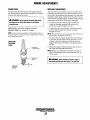
Spark Plugs ..................................................... 29
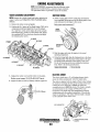
Drive Belt Adjustment. ................................... 29
Electric Choke ................................................ 30
IgnltIon
.. TImlng
. ............................................... 30
Valve Clearance Adjustment .......................... 30
Ignition Wires ................................................. 31
Engine Compression Test .............................. .31
Torquing the Cylinder Head Bolts ................. 31
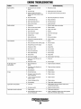
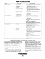
Engine Troubleshooting ....................................32
Troubleshooting Gauges ................................. 35
Transmission (ZF) ............................................. 36
Initial Operation .............................................. 36
Oil Cooler ....................................................... 36
Control Cables ................................................ 37
Shaft Couplings .............................................. 38
Specifications .................................................. 39
Changing Fluid ............................................. ..40
Maintenance .................................................... 40
Troubleshooting ............................................. .41
Transmission (Borg Warner) ............................ .43
Transmission Fluid ........................................ .43
Changing Fluid .............................................. .44
Maintenance .................................................... 45
Troubleshooting ............................................. .46
Lay-up an d Recommlsslonmg
" " " .......................... .48
Engme
" Speci"fIcat"Ions ....................................... 50
Torque Speci"fIcarIons .......................................51
Standard Hardware ............................................ 52
Sealants and Lubricants .................................. 52
Standard and Metric Conversion Data ............. 53
Raw Water Intake Strainer.. ............................ 14 .
Raw Water Pump ............................................ 14
Heat Exchanger .............................................. 15
Thermostat ...................................................... 15
Fuel System ....................................................... 16
Fuel Lift Pump ................................................ 16
Gasdenser ........................................................ 16
Fuel Filter ....................................................... 16
Engine Lubricating Oil .......................................17
Changing the Engine Oil ................................ 17
Oil Pressure .................................................... 18
Remote Oil Filter ............................................... 19
Carburetor Adjustments ................................... .20
Water Heater .....................................................21
DC Electrical System .........................................22
Alternator Troubleshooting ............................ 22
Dual Output Alternators ....................................24
Troubleshooting .............................................. 25
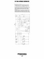
W""
iring Schemat"IC ..............................................26
Suggested Spare Parts ......................................55
W""
Iring D"lag ram ..................................................27
Tachometers ......................................................28
Idle Speed Adjustment.. .................................. 28
Engines & Generators
1
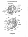
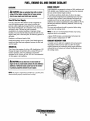
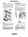
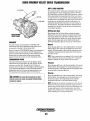
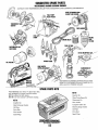
w-70GA PARTS IDENTIFICATION
COOLANT FILLER PRESSURE CAP
FUEL FILTER
EXHAUST ELBOW
WATER INJECTED
FLAME ARRESTER/AIR FILTER
OIL FILL
REAR
RAW WATER PUMP
VACUUM ADVANCE UNIT
FRONT
STARTER MOTOR
DC ALTERNATOR
OIL SUMP-------4-..."ii;
LEFT SIDE
DISTRIBUTER
FUEL
FILTER
COOLANT
PRESSURE CAP
FILL
PCV VALVE
BURETOR
THERMOSTAT
HOUSING
FRONT
HEAT EXCHANGER--k--...p!!J~....
RAW WATER PUMP
20A CIRCUIT
BREAKER
FILTER
TRANSMISSION·
TRANSMISS{ON COUPLING
GAS DENSER
FILTER
....."~. _
SHIFT LEVER
OIL DRAIN HOSE
RIGHT SIDE
REAR
Engines & Generators
2
INTRODUCTION
This WESTERBEKE marine engine is a product of
WESTERBEKE'S long years of experience and advanced
technology. We take great pride in the superior durability
and dependable performance of our engines.Thank you for
selecting WESTERBEKE.
WESTERBEKE CANNOT BE RESPONSIBLE FOR THE CONTENT
OF SUCH SOFTWARE, MAKES NO WARRANTIES OR
REPRESENTATIONS WITH RESPECT THERETO, INCLUDING
ACCURACY, TIMEUNESS OR COMPLETENESS THEREOF AND
WIU IN NO EVENT BE UABLE FOR ANY TYPE OF DAMAGE OR
INJURY INCURRED IN CONNECTION WITH OR ARISING OUT OF
THE FURNISHING OR USE OF SUCH SOFTWARE.
WESTERBEKE customers should also keep in mind the time
span between printings of WESTERBEKE product software
and the unavoidable existence of earlier WESTERBEKE
manuals. In summation, product software provided with
WESTERBEKE products, whether from WESTERBEKE or
other suppliers, must not and cannot be relied upon exclusively as the definitive authority on the respective product. It
not only makes good sense but is imperative that appropriate
representatives of WESTERBEKE or the supplier in question
be consulted to determine the accuracy and currentness of the
product software being consulted by the cUSlomer.
In order to get the full use and benefit from your engine,
it is important that you operate and maintain it correctly.
This manual is designed to help you do this. Please read this
manual carefully and observe all the safety precautions
throughout. Should your engine require servicing, contact
your nearest WESTERBEKE dealer for assistance.
This is your Operators Manual. A Parts Catalog is also
provided and a Technical Manual is available from your
WESTERBEKE dealer. Also, if you are planning to install
this equipment yourself, contact your WESTERBEKE dealer
for WES~RBEKE' S Installation Manual.
WARRANTY PROCEDURES
Your WESTERBEKE Warranty is included in a separate
folder. If you have not received a customer identification card
registering your warranty 60 days after submitting the warranty
registration form, please contact the factory in writing with
model information, including the unit's serial number and
commission date.
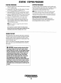
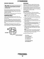
SERIAL NUMBER LOCATION
The engine's model number and serial number are located
on a nameplate mounted on the side of the engine's manifold.
The engine's serial number can also be found etched into the
engine near the top of the engine back plate.
The generator serial number is stamped on the left side of the
generator housing and on the flat surface above the rotary
carrier bearings.
Take the time to enter this information on the illustration of
the nameplate shown below, as this will provide a quick
reference when seeking technical information and/or
ordering repair parts.
I "WV'IWESTERBEKE
I
Engines & Generators
Customer Identification
WESTERBEKE OWNER
MAIN STREET
HOMETOWN, USA
Model
Expires
~2¥fii4;l:143=t
Ser. #
o
•
MODEL
SPEC
AYO, " . ",A
Fill in the infomzation for your reference. ~
PRODUCT SOFTWARE
Product software (tech data, parts lists, manuals, brochures and
catalogs) provided from sources other than WESTERBEKE
are not within WESTERBEKE'S CONTROL.
Engines & Generators
3
0
SER.NO..
INTRODUCTION
ORDERING PARTS
PROTECTING YOUR INVESTMENT
Whenever replacement parts are needed, always provide the
engine model and serial numbers. In addition, include a
complete part description and part number for each part
needed (see the separately furnished Parts Catalog). Also
insist upon WESTERBEKE packaged parts because will fit
or generic parts are frequently not made to the same
specifications as original equipment.
Care at the factory during assembly and thorough testing
have resulted in a WESTERBEKE engine capable of many
thousands of hours of dependable service. However the
manufacturer cannot control how or where the engine is
installed in the vessel or the manner in which the unit is
operated and serviced in the field. This is up to the
buyer/owner-operator.
NOTE: Six important steps to ensure long engine life:
NOTES, CAUTIONS AND WARNINGS
• Proper engine installation and alignment.
As this manual takes you through the operating procedures,
maintenance schedules, and troubleshooting of your engine,
critical information will be highlighted by NOTES,
CAUTIONS, and WARNINGS. An explanation follows:
• An efficient well-designed exhaust system that includes
an anti-siphon break to prevent water from entering the
engine.
NOTE: An operating procedure essential to note.
A
• Changing the engine oil and oil jilters every 100
operating hours.
• Proper maintenance of all engine components according
to the maintenance schedule in this manuaL
CAUTION: Procedures, which if not strictly
observed, can result in the damage or destruction of
• Use clean,jiltered unleadedfueL
the engine.
• Winterize your engine according to the "lo.y-up and
Recommissioning" section in this manual.
A
WARNING: Procedures, which if not properly
UNDERSTANDING THE GASOLINE ENGINE
followed, can result in personal injury or loss of life.
The. gasoline marine engine is in many ways similar to a
gasoline automobile engine. The cylinders are vertical
in-line, and the engine's cylinder head has an overhead
camshaft which is chain-driven. The engine utilizes a solidstate distributor which is horizontally mounted and camshaftdriven. The engine incorporates a pressure type lubrication
system, and a fresh water-cooled engine block which is
thermostatically-controlled. To a large degree, the marine
engine requires the same preventive maintenance that is
required of a gasoline automobile engine. The most
important factors to the engine's longevity are proper
ventilation, maintenance of the fuel system, ignition system,
cooling system and the lubrication system.
NOTE: A carbon monoxide warning decal has been provided
by WESTERBEKE. Affix this decal in a visable location in
the engine room.
SPARES AND ACCESSORIES
Certain spare parts will be needed to support and maintain
your WESTERBEKE engine when cruising (see
SUGGESTED SPARE PARTS). Often even simple items such
as proper fuel and oil filter can be difficult to obtain along
the way. WESTERBEKE will provide you with a suggested
spares and accessories brochure to assist you in preparing an
on-board inventory of the proper WESTERBEKE parts.
Engines & Generators
4
FUEL, ENGINE OIL AND ENGINE COOLANT
ENGINE COOLANT
GASOLINE
WESTERBEKE recommends a mixture of 50% antifreeze and
50% distilled water. Distilled water is free from the chemicals
that can corrode internal engine surfaces.
The antifreeze performs double duty. It allows the engine
to run at proper temperatures by transferring heat away from
the engine to the coolant. It also lubricates and protects the
cooling circuit from rust and corrosion. Use a good quality
antifreeze that contains supplemental cooling additives (SCAs)
that keep the antifreeze chemically balanced, crucial to long
term protection.
The water and antifreeze should be premixed before being
poured into the cooling circuit.
A CAUTION: Only use unleaded fuel with an octane
rating of 89 or higher. Leaded fuel will cause serious
harm to your engine and violate your warranty.
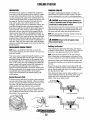
Care Of The Fuel Supply
Use only clean fuel! The clearance of the components in
your fuel injection pump is very critical; invisible dirt
particles which might pass through the filter can damage
these finely finished parts. It is important to buy clean fuel,
and keep it clean. The best fuel can be rendered
unsatisfactory by careless handling or improper storage
facilities. To assure that the fuel going into the tank for your
engine's daily use is clean and pure, the following practice is
advisable:
Purchase a well-known brand of fuel.
Install and regularly service a good, Coast Guard approved
metal bowl type filterlwater separator between the fuel tank
and the engine.
NOTE: Use the new environmentally-friendly, long lasting,
antifreeze that is now available.
A proper 50150 mixture as recommended will protect the
engine coolant to temperatures of -4O"F
COOLANT RECOVERY TANK
A coolant recovery tank kit is supplied with each generator.
The purpose of this recovery tank is to allow for engine
coolant expansion and contraction during engine operation,
without the loss of coolant and without introducing air into
the cooling system.
ENGINE OIL
Use a heavy duty engine oil with an API classification of SJ.
Change the engine oil and filter after an initial 50 hours of
break-in operation, and every 100 hours of operation
thereafter.An oil viscosity of SAE 15W-40 is recommended
for this engine in all conditions.
A CAUTION: 00 not allow two or more brands of
engine oil to mix. Each brand contains its own additives;
additives of different brands could react in the mixture
to produce properties harmful to your engine.
NOTE: The engine compartment should have a gasoline fume
detector/alarm properly installed and working.
Engines & Generators
5
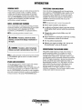
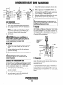
GASOLINE ENGINE INSTRUMENT PANEL
NOTE: Be certain to install the instrument panel in a location
that is accessible and where the gauges can be continually
monitored by the helmsman.
The following is a description of the panel components.
Tachometer - Registers revolutions per minute of the engine
and measures the engines total elapsed time in hours and 111 0
hours. Refer to TACHOMETER for calibration.
DESCRIPTION
Key switch - Turned to the 2 o'clock position [on], the key
switch energizes the panel. {Illuminates the gauges and
activates the start button.]
The marine gasoline engine is equipped with an [optional]
key start instrument panel. This panel connects to the engine
wiring harness thru a 15 foot plug-in harness.
Prestart Button - A "push-to-start" rubber booted pushbutton
that is energized by the key switch. Pressing this button
activates the fuel lift pump.
Included with the panel is an alarm buzzer. This alarm buzzer
will sound when the ignition key is turned on and should
silence when the engine has started and the oil pressure rises
above 5 psi. The installer is responsible for installing this
alarm buzzer in a dry location where it will be audible to the
operator with the engine running.
Start Button - Identical to the prestart button, the start button,
when pressed, energizes the starter which cranks the engine.
Oil Pressure Gauge - Measures the engines oil pressure in
pounds per square inch. The alarm buzzer will sound if the oil
pressure falls below 10 psi. This alarm will briefly sound when
the engine is first started prior to oil pressure being produced.
NOTE: It is the responsibility of the installer to make certain
the alann wiring is properly routed and supported to its
connections on the engine.
Voltage Gauge - Measures the voltage in the DC circuit [the
amount the battery is being charges 13V to 14V].
Water Temperature Gauge - Indicates the temperature of
the engine coolant. If the coolant temperature reaches 210"F
[99°C], the alarm buzzer will sound a continuous signal.
NOTE: The water temperature gauge and oil temperature will
register the last reading when the engine is shut down. The true
temperatures will register when the power is turned back on.
GASOLINE ENGINE
INSTRUMENT PANEL
Engines & Generators
6
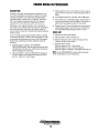
PREPARATIONS FOR INITIAL START-UP
PRESTART INSPECTION
D Visually examine the engine. Look for loose or missing
Before starting your engine for the first time or after a prolonged layoff, check the following items:
D Check the engine oil level. Add oil to maintain the level
at the high mark on the dipstick.
D Turn on the fuel supply, then check the fuel supply and
examine the fuel fIlter/water separator bowl for contaminants.
D Check the transmission fluid level.
D
D
D
D
NOTE: Refer to the specifications pages in this manual for
fuel, oil and transmission fluid types and quantities.
D Check the DC electrical system. Inspect wire connections
parts, disconnected wires, and unattached hoses. Check
the threaded connections and engine attachments.
Examine the air inlet and outlet for air flow obstructions.
Good ventilation and an ample air supply are necessary
for proper engine performance.
Make sure the mounting installation is secure.
Ensure the propeller shaft is securely attached to the
transmission.
Open the through-hull and prime the raw water intake
strainer. Inspect the raw water supply.
A
and battery cable connections. Make certain the positive
(+) battery cable is connected to the starter solenoid and
the negative (-) cable is connected to the engine ground
stud (this location is tagged).
D Check the coolant level in both the plastic recovery tank
and at the manifold.
CAUTION: Do not pull the dipstick when the
engine is running.
NOTE: If the engine has not yet been filled with coolant,
refer to the COOliNG SYSTEM section of this manual
DIPSTIC
OIL FILL
/IOILLEVEL
-- -----
EXHAUST MANIFOLD
Engines & Generators
7
STARTING • STOPPING PROCEDURE
STARTING PROCEDURE
STOPPING PROCEDURE
1. Place the transmission in neutral and advance the throttle
To stop the engine, bring the throttle to an idle position and
place the transmission in neutral. Allow the engine to idle for
a few moments to stabilize temperatures, then shut the
engine down by turning off the key switch.
2.
3.
4.
5.
6.
control to slightly open.
Tum the KEY SWITCH to the ON position (2 o'clock).
(If the panel is energized, the gauges are on.)
Press the PREHEAT BUTTON, and hold for 5 seconds.
(The fuel lift pump is priming the engine fuel system.)
Release the PRESTART BUTTON and press the START
BUTTON. (The starter motor is cranking the engine).
Release the START BUTTON as the engine starts.
With the engine running, check the instruments for
proper oil pressure and battery charging voltage. The
water temperature will rise slowly and then stabilize
when the thermostat opens.
NOTE: Make certain this key switch is in the OFF position
(12 o'clock). If the key switch is left ON, the energized
instrument panel will put a drain on the battery. The alarm
will pulsate warning that the key is still in the ON position.
Starting Under Cold Conditions
Make certain the lubricating oil is appropriate for the
prevailing temperature. Use oil with an API Specification
of SJ or better, SAE 30, lOW-30, or 15W-40.
NOTE: Never attempt to engage the starter while the
engine is running.
It is important to closely monitor the panel gauges.
Become aware of the normal engine readings and take
immediate action if these readings start to vary.
FAILURE TO START
If the engine fails to start when the start button is pressed for
5 seconds, wait for at least 30 seconds and repeat the starting
procedure. Make certain the transmission control is in the
neutral position as some engines have a neutral safety switch
to prevent starting in gear.
Never run the starter for more then 30 seconds. If the engine
fails to start, refer to the TROUBLESHOOTING CHART in
this manual.
A CAUTION: Prolonged cranking intervals without
the engine starling can result in the engine exhaust
system filling with raw water. This may happen because
the pump is pumping raw water through the raw water
cooling system during cranking. This raw water can
enter the engine's cylinders by way of the exhaust
manifold once the exhaust system fills. Prevent this
from happening by closing the raw water supply
through-hull shutoff, draining the exhaust muffler, and
correcting the cause of the excessive engine cranking.
Engine damage resulting from raw water entry is not a
warrantable issue; the owner/operator should keep this
in mind.
Engines & Generators
8
ENGINE BREAK-IN PROCEDURE
DESCRIPTION
3. While using the vessel, run the engine at various engine
speeds for the fIrst 25 hours. Avoid prolonged periods of
idling.
4. Avoid rapid acceleration, especially with a cold engine.
5. Use caution not to overload the engine. The presence of
a grey or black exhaust and the inability of the engine to
reach its full rated speed are signs of an overload.
6. During the next 25 hours, the engine may be operated at
varying engine speeds, with short runs at full rated rpm.
Avoid prolonged idling during this break-in period.
Although your engine has experienced a minimum of one
hour of test operations at the factory to make sure accurate
assembly procedures were followed and that the engine
operated properly, a break-in time is required. The service
life of your engine is dependent upon how the engine is
operated and serviced during its initial 50 hours of use.
Breaking-in a new engine basically involves seating the
piston rings to the cylinder walls. Excessive oil consumption
and smoky operation indicate that the cylinder walls are
scored, which is caused by overloading the engine during the
break-in period.
Your new engine requires approximately 50 hours of initial
conditioning operation to break in each moving part in order
to maximize the performance and service life of the engine.
Perform this conditioning carefully, keeping in mind the
following:
1. Start the engine according to the STARTING
PROCEDURE section. Run the engine at fast idle while
checking that all systems (raw water pump, oil pressure,
battery charging) are functioning.
2. Allow the engine to warm up (preferably by running at
fast idle) until the water temperature gauge moves into
the 130 - 1400 P (55 - 60°C) range.
CHECK LIST
o
o
o
o
Monitor the control panel gauges.
Check for leaks of fuel and engine oil.
Check for abnormal noise such as knocking, friction,
vibration and blow-back sounds.
ConfIrm exhaust smoke:
When the engine is cold - white smoke.
When the engine is warm - almost smokeless.
When the engine is overloaded - some black smoke and soot
NOTE: See the TRANSMISSION section of this manualfor
break-in information on your transmission.
Engines & Generators
9
THE DAILY OPERATION
CHECK LIST
2. Tum the KEY SWITCH to the ON position (2 o'clock).
[The panel is energized, gauges are lit}.
Follow this check list each day before starting your engine.
3. Depress the PRESTART BUTTON, hold for 5 seconds.
[The fuel lift pump is priming the engine).
D Visually inspect the engine for fuel, oil, or water leaks.
D Check the oil level (dipstick).
D Check the coolant level in the coolant recovery tank.
4. Release the PRESTART BUTTON and press the START
BUTTON. [The start motor is cranking the engine}.
Periodically check the manifold coolant level.
D
D
D
D
5. Release the START BUTTON as the engine starts.
6. With the engine running, check the instruments for
Check the transmission fluid level.
Check your fuel supply.
proper oil pressure and battery charging voltage. The
water temperature will rise slowly until the thermostat
opens.
Look for clean fuel in the fuel filter/water separator
transparent bowl.
Check for loose wires at the alternator and make sure its
mounting is secure.
NOTE: Never attempt to engage the starter while the
engine is running.
D Check the starting batteries (weekly).
D Check drive belts for wear and proper tension (weekly).
D Visually inspect the raw water pump for leakage.
Stopping Procedure
To stop the engine, bring the throttle to an idle position and
place the transmission in neutral. Allow the engine to idle for
a few moments to stabilize temperatures. Then shut the
engine down by turning off the key switch at the same time
put the throttle at full open ..
STARTING THE ENGINE
NOTE: See STARTING/STOPPING PROCEDURE in this
manual for more detailed instructions.
NOTE: Make certain this key switch is in the OFF
position( 120 'clock). If the key switch is left ON, the
energized instrument panel will put a drain on the battery.
The engine pulse alarm will sound as a reminder that the key
switch has been left on.
1. Put the transmission in neutral, throttle advanced.
NOTE: Hydraulically operated transmissions have a
neutral safety switch through which the starter solenoid
energizing circuit passes. This switch is open when the
transmission is in gear so the starter solenoid will not
energize.
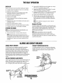
ALARMS AND CIRCUIT BREAKER
ENGINE CIRCUIT BREAKER
COOLANT TEMPERATURE SWITCH
The DC harness on the engine is protected by an enginemounted manual reset circuit breaker (20 amps DC).
Excessive current draw or electrical overload anywhere in
the instrument panel wiring or engine wiring will cause the
breaker to trip. In this event most engines will shut down
because the open breaker disconnects the fuel supply. If
this should occur, check and repair the source of the problem.
After repairing the fault, reset the breaker and restart the
engine.
A coolant temperature switch is located on the thermostat
housing. This switch will activate a continuous alarm if the
coolant's operating temperature reaches approximately
210°F (99°C).
COOLANT
TEMPERATURE
SWITCH
LOW OIL PRESSURE ALARM SWITCH
Allow oil pressure alarm switch is located off the engine's oil
gallery. This switch's sensor monitors the engine's oil pressure. Should the engine's oil pressure fall to 5 -10 psi
(0.4 - 0.7 kg!cm2), this switch will activate a pulsating alarm.
~
'1////"
Engines & Generators
10
/"
~
;". AIR BLEED
PETCOCK
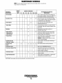
MAINTENANCE SCHEDULE
A WARNING: Never attempt to perform any service while the engine is
running. Wear the proper safety equipment such as goggles and gloves, and
use the correct tools for each job. Disconnect the battery terminals when
servicing any of the engine's DC electrical equipment.
NOTE: Many o/the/ollowing maintenance jobs are simple but others are
more difficult and may require the expert knowledge 0/ a service mechanic.
SCHEDULED
MAINTENANCE
CHECK
EACH
DAY
HOURS OF OPERATION
50
100
250
500
750 1000 1250
EXPLANATION OF SCHEDULED
MAINTENANCE
Fuel Supply
0
Unleaded gasoline with octane rating of 89 or
higher.
FueljWater Separator
0
Check for water and dirt in fuel (drain/replace filter
if necessary).
Engine Oil Level
0
Oil level should indicate between FULL and LOW on
dipstick.
Coolant Level
0
Check at recovery tank; if empty, check at manifold.
Add coolant if needed.
0
Inspect for proper tension (3/8' to 1/2" deflection)
and adjust if needed. Check belt edges for wear.
Drive Belts
weekly
Visual Inspection of Engine
0
Spark Plugs
and oil will inhibit the engine's ability to
remain cool.
0
0
Generator (if applicable)
Fuel Filter (Lift Pump)
Starting Batteries
(and House Batteries)
NOTE: Please keep engine surface clean. Dirt
0
0
0
0
Re-torque Cylinder Head
0
0
Air Screen (Flame Arrester)
Exhaust System
0
0
0
0
0
0
0
0
0
0
0
0
0
0
0
0
0
Check that AC connections are clean and secure
with no chafing - see GENERATOR INFORMATION
(if applicable) for addition information.
Inspect for fuel leaks. Check wire connections.
Initial engine oil & filter change at 50 hrs., then
change both every 100 hours.
Retorque at 50 hrs., them every 500 hours.
0
0
0
0
Initial adjustment at 50 hrs., then every 500 hrs.
Clean at 50 hours, then every 100 hours.
0
0
0
Check gap; inspect for burning and corrosion.
Every 50 operating hours check electrolyte levels
and make sure connections are very tight. Clean off
excessive corrosion.
0
0
Engine Hoses
Inlet Fuel Filter
0
0
weekly
Engine Oil
*Adjust the Valve
Clearances
0
0
0
Check for fuel, oil and water leaks. Inspect wiring
and electrical connections. Keep bolts & nuts tight.
Check for loose belt tension.
0
0
Initial check at 50 hrs., then every 250 hrs. Inspect
for leaks. Check siphon brake operation. Check the
exhaust elbow for carbon and/or corrosion buildup
on inside passages; clean and replace as necessary.
Check that all connections are tight.
0
0
0
0
0
Hose should be hard & tight. Replace if soft or
spongy. Check and tighten all hose clamps.
0
0
0
0
0
Replace every 200 operating hours.
continued
Engines & Generators
11
MAINTENANCE SCHEDULE
NOTE: Use the engine hourmeter gauge to log your engine hours or record your
engine hours by running time.
SCHEDULED
MAINTENANCE
Heat Exchanger
CHECK
EACH
DAY
HOURS OF OPERATION
50
D
100
D
250
D
500
D
EXPLANATION OF SCHEDULED
MAINTENANCE
750 1000 1250
D
D
D Clean or replace anode. Open heat exchanger end
cap and clean out debris. remove every 1000 hours
for professional cleaning and pressure testing.
D
Raw Water Pump
Coolant System
D
D
D
*Exhaust Elbow
D
Lubricate Panel Key
Switch with "Lockeze"
Carburetor Filter
Screen
D
D
Incorrect valve clearance will result in poor engine
performance. Check compression pressure and
timing and adjust valve clearances.
Test exhaust elbow for casting integrity. Replace if
casting is corroded or deteriorated.
WARNING: A defective exhaust elbow can cause
carbon monoxide leakage.
At first 100 hours. Then each year at winterizing or
once a season.
D
D
Check solenoid and motor for corrosion. Remove
and lubricate. Clean and lubricate the starter motor
pinion drive.
Check ignition timing. Check condition of
distributor cap and rotor.
D
*Engine Cylinder
Compression and
Valve Clearance
Remove the pump cover and inspect the impeller
for wear, replace if needed. Also replace the gasket.
Lubricate both when re-assembling.
Drain, flush, and refill cooling system with
appropriate antifreeze mix.
D
*Starter Motor
Distributor
D
D
D
D
D
D
Clean at first 50 hours and every 250 hours.
Transmission Fluid
Refer to the TRANSMISSION section.
Transmission Damper Plate
D
Seperate the transmission from the engine and
inspect the damper plate, look for wear or broken
springs, replace if necessary.
D
Inspect for leaks and condition of the casting,
replace if needed.
D
Inspect engine mountinglisolators. If upper cap is
contacting the base replace the mount.
Transmission Cooler
D
Engine Mounts/lsolators
*WESTERBEKE recommends this service be performed by an authorized mechanic.
Engines & Generators
12
COOLING SYSTEM
DESCRIPTION
CHANGING COOLANT
Westerbeke marine engines are designed and equipped for
fresh water cooling. Heat produced in the engine by combustion and friction is transferred to fresh water coolant which
circulates throughout the engine. TIris circulating fresh water
coolant cools the engine block, its internal moving parts, and
the engine oil. The heat is transferred externally from the
fresh water coolant to raw water by means of a heat
exchanger, similar in function to an automotive radiator. Raw
water flows through the tubes of the heat exchanger while
fresh water coolant flows around the tubes; engine heat transferred to the fresh water coolant is conducted through the
tube walls to the raw water which is then pumped into the
exhaust system where finally it is discharged overboard. In
other words, the engine is cooled by fresh water coolant, this
coolant is cooled by raw water, and the raw water carries the
transferred heat overboard through the exhaust system. The .
fresh water coolant and raw water circuits are independent of
each other. Using only fresh water coolant within the engine
allows the cooling water passages to stay clean and free from
harmful deposits.
The engine's coolant must be changed according to the
MAINTENANCE SCHEDULE. -If the coolant is allowed to
become contaminated, it can lead to overheating problems.
critical; a substantial number of engine failures can be
traced back to cooling system corrosion.
Drain the engine coolant by loosening the drain plug on the
engine block and opening the manifold pressure cap. Flush
the system with fresh water, then start the refill process.
NOTE: The drain petcock on the heat exchanger should also
be used to help drain engine coolant.
A WARNING: Beware of the hot engine coolant.
Wear protective gloves.
Refilling the Coolant
FRESH WATER COOLING CIRCUIT
After replacing the engine block drain plug, close the heat
exchanger's coolant petcock. Then run the engine at idle and
slowly pour clean, premixed coolant into the manifold.
NOTE: Refer to the ENGINE COOlANT section for the
recommended antifreeze and water mixture to be used as the
fresh water coolant.
NOTE: Open the air-bleed petcock on the heat exchanger.
When a steady flow of coolant appears at the petcock, close
the petcock and fill the system until the manifold remains full.
Fresh water coolant is pumped through the engine by a circulating pump, absorbing heat from the engine. The coolant
then passes through the thermostat into the manifold, to the
heat exchanger where it is cooled, and returned to the engine
block via the suction side of the circulating pump. When the
engine is started cold, external coolant flow is prevented by
the closed thermostat (although some coolant flow is
bypassed around the thermostat to prevent the exhaust manifold from overheating). As the engine warms up, the thermostat gradually opens, allowing full flow of the engine's
coolant to flow unrestricted to the external portion of the
cooling system.
~oolant
A CAUTION: Proper cooling system maintenance is
Monitor the coolant in the manifold and add as needed. Fill
the manifold to the filler neck and install the manifold pressure cap.
Remove the cap on the coolant recovery tank and fill with
coolant mix to halfWay between LOW and MAX and replace
the cap. Run the engine and observe the coolant expansion
flow into the recovery tank.
After checking for leaks, stop the engine and allow it to cool.
Coolant should draw back into the cooling system as the
engine cools down. Add coolant to the recovery tank if
needed. Clean up any spilled coolant.
Recovery Tank
A coolant recovery tank allows for engine coolant expansion
and contraction during engine operation, without any significant loss of coolant and without introducing air into the cooling system. TIris tank should be located at or above the
engine manifold level and should be easily accessible.
NOTE: Periodically check the condition of the manifold pressure cap. Ensure that the upper and lower rubber seals are in
good condition and check that the vacuum valve opens and
closes tightly. Carry a spare cap.
COOLANT EXPANSION
COOLANT RETRACTION
Engines & Generators
13
COOLING SYSTEM
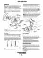
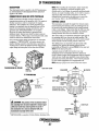
RAW WATER INTAKE STRAINER
RAW WATER PUMP
NOTE: Always install the strainer at or below the waterline so
the strainer will always be self-priming.
Perform the following maintenance after every 100 hours of
operation:
1. Close the raw water seacock.
2. Remove and clean the strainer filter.
The raw water pump is a self-priming, rotary pump with a
non-ferrous housing and a Neoprene impeller. The impeller
has flexible blades which wipe against a curved cam plate
within the impeller housing, producing the pumping action.
On no account should this p"ump" be run dry. There should
always be a spare impeller and impeller cover gasket aboard
(an impeller kit). Raw water pump impeller failures occur
when lubricant (raw water) is not present during engine
operation. Such failures are not warrantable, and operators
are cautioned to make sure raw water flow is present at startup. The raw water pump should be inspected periodically for
broken or tom impeller blades. See MAINTENANCE
3. Clean the glass.
SCHEDULE.
4. Replace the sealing washer if necessary.
5. Reassemble and install the strainer.
NOTE: Should a failure occur with the pump s internal parts
(seals and bearings), it may be more cost efficient to purchase a new pump and rebuild the original pump as a spare.
A clean raw water intake strainer is a vital component of the
engine's cooling system. Include a visual inspection of this
strainer when making your periodic engine check. The water
in the glass should be clear.
6. Open the seacock.
7. Run the engine and check for leaks.
Changing the Raw Water Pump Impeller
NOTE: Also follow the above procedure after having run hard
aground.
Close the raw water intake valve. Remove the pump cover
and, with the aid of two small screwdrivers, carefully pry the
impeller out of the pump. Install the new impeller and gasket.
Move the blades to conform to the curved cam plate and
push the impeller into the pump's housing. When assembling, apply a thin coating oflubricant to the impeller and
gasket. Open the raw water intake valve.
Run the engine and check for leaks around the pump. Also
check for water discharge at the stem tube. Absence of water
flow indicates the pump has not primed itself properly.
If the engine temperature gauge ever shows a higher than
normal reading, the cause may be that silt, leaves or grass
may have been caught up in the strainer, slowing the flow of
raw water through the cooling system
RAW WATER PUMP
RAW WATER INTAKE STRAINER
TYPICAL [OWNER INSTALLED]
INCOMING
RAW WATER
A CAUTION: If any of the vanes have broken off the
impeller, they must be located to prevent blockage in
the cooling circuit. They often can be found in the heat
exchanger
Engines & Generators
14
COOLING SYSTEM
THERMOSTAT
If the zinc pencil needs replacement, hold the hex boss into
which the zinc pencil is threaded with a wrench while
loosening the anode with another wrench. This prevents the
hex boss from possibly tearing off the exchanger shelL After
removing the zinc, note the condition. If the zinc is in poor
condition, there are probably a lot of zinc flakes within the
exchanger. Remove the end cap of the heat exchanger and
clean the inside of all zinc debris. Always have a spare heat
exchanger end gasket in case the present one becomes
damaged when removing the end cover. Replace the sealing
gasket (refer to your engine model's heat exchanger end gasket
part number), O-ring and cover, and install a new zinc anode.
A thennostat controls the coolant temperature as the coolant
continuously flows through the closed cooling circuit. When
the engine is first started the closed thennostat prevents
coolant from flowing (some coolant is by-passed through tile
thennostat to prevent the exhaust manifold from overheating). As the engine wanns up, the thennostat gradually
opens. The thennostat is accessible and can be checked
cleaned, or replaced easily. Cany a spare thennostat and.
gasket.
THERMOSTAT
NOTE: The threads of the zinc anodes are pipe threads and do
not require sealant. Sealant should not be used as it may
insulate the zinc from the metal of the heat exchanger
housing preventing electrolysis action on the zinc.
THERMOSTAT TEST
If you suspect a faulty thennostat, place it in a pan of water and
bring to a boiL A working thennostat should open about 112".
ZINC ANODE
HEAT EXCHANGER
A zinc anode (or pencil) is located in the raw water cooling
circuit within the heat exchanger. The purpose of the zinc
~node is to sacrifice itself to electrolysis action taking place
m the raw water cooling circuit, thereby reducing the effects
of electrolysis on other components of the system. The condition of the zinc anode should be checked monthly and the
anode cleaned or replaced, as required. Spare anodes should
be carried onboard.
Cool raw water flows through the inner tubes of the heat
exchanger. As the engine coolant passes around these tubes
the heat of the internal engine is conducted to the raw water
which is then pumped into the exhaust system and discharged.
The engine coolant (now cooled) flows back though the
engine and the circuit repeats itself.
The engine coolant and raw water are independent of each
other; tins keeps the engine's water passages clean from the
hannful deposits found in raw water.
Heat Exchanger Service
NEW
REPLACE
After approximately 1000 hours of operation, remove, clean
and pressure test the engine's heat exchanger. (A local automotive radiator shop should be able to clean and test the heat
. exchanger).
CLEAN & REUSE
NOTE: Operating in silty a1ld/or tropical waters may require
that a heat exchanger cleaning be peifol71zed nwre often then
every 1000 hours.
NOTE: Electrolysis is the result of each particular installation
and vessel location, not that of the engine.
Engines & Generators
15
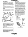
FUEL SYSTEM
GASOLINE
Use unleaded 89 octane or higher gasoline. When fueling,
follow U.s. Coast Guard regulations, close off all hatches and
companionways to prevent fumes from entering the boat, and
ventilate after fueling.
NOTE: The generator compartment should have a gasoline
fume detectorlalann properly installed and working.
GASDENSER
AWARNING: Shut off the fuel valve at the tank
The gasdenier consists of a portion of the fuel line that is coiled
around the raw water intake line and insulated. It is located .
between the raw water intake and the raw water pump. The gasdenser cools the fuel to prevent vapor lock.
when servicing the fuel system. Take care in catching any fuel that may spill. DO NOT allow any smoking, open flames or other sources of fire near the
fuel system when servicing. Ensure proper ventilation exists when servicing the fuel system.
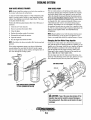
ENGINE FUEL FILTER
Periodically check the fuel connections and the filter bowl for
leakage. Change the filter element after the first 50 hours. See
MAINTENACE SCHEDULE.
GASOLINElWATER SEPARATOR AND FILTER
A primary fuel filter of the water separating type must be
installed between the fuel tank and the engine to remove
water and other contaminants from the fuel before they can
be carried to the fuel system on the engine.
Most installers include a type of filter/water separator with
the generator installation package as they are well aware of
the problems that contaminants in the fuel can cause.
.
These gasoline filters must have metal bowls (not "seethrough") to meet U.s. Coast Guard requirements. The metal
bowls have drain valves to use when checking for water and
impurities.
,.
Changing the Filter Element
1. Shut off fuel supply.
2. Unscrew the retainer ring that holds the filter bowl to the
housing and allow bowl to come away from the housing.
3. Remove and replace the filter element and clean the bowl.
4. Replace the sealing "0" ring and reassemble the bowl to
the housing. Thread the retainer ring on carefully so as not
to cross thread. When retainer contacts the "0" ring,
tighten 114 - 1/2 turnes by hand. Open the fuel supply and
run the engine to inspect for leaks.
A WARNING: Fuel is present in the housing and lines.
FUEL FILTER
WATER SEPE~TOR
Owner Installed
Use extreme care to prevent spillage.
RACOR
MODEL 110A
ILLUSmATED
HOUSING
FUEL LIFT PUMP
Periodically check the fuel connections to and out of the pump
and make sure that no leakeage is present and that the fittings
are tight and secure. The DC ground connection at one of the
pump's mounting bolts should be clean and well secured by
the mounting bolt to ensure proper pump operation.
The engine mounted fuel lift pump is maintenance free.
,Ik---FILTER
'ELEMENT
----O-RING
INLET FUEL FILTER
To ensure clean fuel enters the fuel lift pump, there is an
in-line filter at the incoming fuel line. This filter should be
replaced every 200 operating hours.
I~~~mk-_-RETAINING
'II
RING
Engines & GEmerators
16
ENGINE LUBRICATING OIL
DESCRIPTION
CHANGING THE ENGINE OIL
The lubricating system is a pressure feeding system using an
oil pump. The engine oil is drawn from the oil sump by the
oil pump, which drives the oil, under pressure, through the
oil filter, oil cooler and various lubricating points in the
engine. The oil then returns to the oil sump to repeat the
continuous cycle. Wbyn the oil pressure exceeds the
specified pressure, the oil pushes open the relief valve in the
oil pump and returns to the oil sump, keeping the oil pressure
within its specified range.
The engine oil should be wann. Remove the oil drain hose
from its attachment bracket and lower it into a container and
allow the oil to drain, or attach a pump to the end of the drain
hose and pump the old oil out. Make sure the oil drain hose
is properly secured in its holder after all of the old oil has
been drained.
Always observe the old oil as it is removed. A yellow/gray
emulsion indicates the presence of water in the oil. Although
this condition is rare, it does ·require prompt attention to
prevent serious damage. Call a competent mechanic if water
is present in the oil. Raw water present in the oil can
be the result of a fault in the exhaust system attached to the
engine and/or a siphoning through the raw water cooling
circuit into the exhaust, filling into the engine.
LUBRICATION
DIAGRAM
ENGINE OIL
Use a heavy duty engine oil with an API classification of SJ.
Change the engine oil and filter after an initial 50 hours of
break-in operation, and every 100 hours of operation
thereafter.An oil viscosity of SAE 15W-40 is recommended
for this engine in all conditions.
TIGHTEN BY HAND
MOISTEN THE NEW
FILTER GASKET WITH
CLEAN OIL WHEN
INSTALLING
A WARNING: Used engine oil contains harmful
A CAUTION: Do not allow two or more brands of
contaminants. Avoid prolonged skin contact. Clean skin
and nails thoroughly using soap and water. Launder or
discard clothing or rags containing used oil. Discard
used oil properly.
engine oil to mix. Each brand contains its own additives;
additives of different brands could react in the mixture
to produce properties harmful to your engine.
Engines & Generators
17
ENGINE LUBRICATING OIL
REPLACING THE OIL FILTER
LOW OIL PRESSURE
When removing the used oil filter, you may find it helpful to
punch a hole in the upper and lower portion of the old filter
to drain the oil into a container before removing it. This helps
to lessen spillage. An automotive filter wrench should be
helpful in removing the old filter. Place some paper towels
and a plastic bag around the filter when unscrewing it to catch
any oil that's in the filter. Inspect the old oil filter as it is
removed to make sure that the rubber sealing gasket comes
off with the filter. If this rubber sealing gasket remains sealed
against the oil filter adapter, gently remove it. When
installing the new filter element, wipe the filter gasket's
sealing surface on the filter adapter free of oil and apply a
thin coat of clean engine oil to the rubber sealing gasket.
Screw on the filter and tighten the filter firmly by hand.
The specified safe minimum oil pressure is 4.3 + 1.4 psi (0.3
+ 0.1 kglcm2). A gradual loss of oil pressure usually indicates
worn bearings. For additional information on low oil pressure
readings, see the ENGINE TROUBLESHOOTING chart.
NOTE: Use genuine WESTERBEKE oil filters. Genericfilters
are not recommended.
REFILLING THE OIL SUMP
Add fresh oil through the valve cover. After refilling the oil,
run the engine for a few moments while checking the engine's
oil pressure. Make sure there is no leakage around the new
oil filter or from the oil drain system, and then stop the
engine. Then check the quantity of oil with the lube oil
dipstick. Fill to, but not over, the FULL mark.
\
TESTING OIL PRESSURE
To test the oil pressure, remove the oil pressure sender, then
install a mechanical oil pressure gauge in its place. After
warming up the engine, set the engine speed at 3000 rpm
and read the oil pressure gauge.
OIL PRESSURE
The engine's oil pressure, during operation, is indicated
by the oil pressure gauge on the instrument panel. During
normal operation, the oil pressure will range between 40 and
75 psi (2.8 and 5.2 kglcm2).
OIL PRESSURE
35.0 Ib/in' (3.8 kg/em') or higher at 3000 rpm.
SENDER AND SWITCH TORQUE
9 -13 ft-Ib (1.2 -1.8 m - kg).
NOTE: A newly started, cold engine can have an oil pressure
reading up to 80 psi (5.6 kg!cm 2). A warmed engine can have
an oil pressure reading as low as 35 psi (2.5 kg!cm 2). These
readings will vary depending upon the temperature of the
engine and the rpms.
Engines & Generators
18
REMOTE OIL FILTER (OPTIONAL)
INSTALLATION
To install, simply remove the engine oil filter and thread on
WESTERBEKE's remote oil filter kit as shown. Always
install this kit with the oil filter facing down as illustrated.
This popular accessory is used to relocate the engine's oil filter from the engine to a more convenient location such as an
engine room bulkhead.
Contact your WESTERBEKE dealer for more information.
NOTE: Refer to ENGINE OIL CHANGE in this manualfor
instructions on changing the oil filter.
NOTE: Westerbeke is not responsible for engine failure due to
incorrect installation of the Remote Oil Filter.
APPLY A THIN COAT OF CLEAN OIL TO THE O-RING WHEN
INSTAlliNG THIS KIT. THREAD THE KIT ON. THEN HAND
TIGHTEN AN ADDITIONAL 3/4 TURN AFTER THE O-RING
CONTACTS THE BASE.
FASTEN SECURELY TO A BULKHEAD
(SCREWS ARE OWNER SUPPLIED)
NOTE: THE "IN" AND "OUT" MARKINGS
ON THE ADAPTER WHEN THE HOSES ARE
REMOVED FOR INSTALLATIONS SO THEY
Will BE RECONNECTED CORRECTLY.
APPLY A THIN COAT OF CLEAN OIL TO THE
FILTER GASKET WHEN INSTALLING. AFTER THE
FILTER CONTACTS THE BASE. TIGHTEN IT AN
ADDITIONAL 3{4 TURN.
Engines & Generators
19
CARBURETOR ADJUSTMENTS
NOTE: WESTERBEKE recommends that the following engine
adjustments be performed by a competent engine mechanic.
The information below is provided to assist the mechanic.
Carburetor Filter Screen
.CARBURETOR
Clean this filter element after the first 50 hours of operation,
then clean and inspect every 250 operating hours. Replace
the screen if necessary. Tighten the plug and make certain
there are no leaks.
The carburetor is a single barrel, down-draft type with a
cleanable metal screen air intake.
The choke is operated by a 12V DC current. After the engine
starts (cold start), the choke circuit is kept activated opening
the choke. This helps prevent stalling on a cold start. The
circuit remains active until shutdown.
Idle Mixture Jet
Adjustment is performed with the engine operating. Screw
the jet slowly in until it seats, then back it out 1-112 to 2
turns.
Air Screen/Flame Arrester
The air screen/flame arrester can easily be removed by
releasing the hold-down clamp. Clean after the first 50 hours
of operation, every 100 hours from then on. Clean the air
screen in kerosene and blow dry with air.
Note: An idle mixture jet adjusted too far off its seat can
induce a sooty exhaust discharge at engine start-up and
shut-down.
TO ROCKER
COVER
AIR SCREEN
FLAME ARRESTER
FROM FUEL FILTER
SEE ELECTRIC CHOKE
IN THIS MANUAL UNDER
ENGINE ADJUSTMENTS
IDLE MIXTURE JET
FILTER SCREEN
ACCELLERTAOR
PUMP COVER
Engines & Generators
20
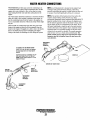
WATER HEATER CONNECTIONS
WESTERBEKE provides easy access for connecting to an
on-board hot water system. These connections allow for the
engines hot water (coolant) to flow to the ships hot water
tank, heating the fresh water and then cycling back to the
engine.
The water heater should be mounted in a convenient location
either in a high or low position in relation to the engine, so
that the connecting hoses from the heater to the engine can
run in a reasonably direct line without any loops which might
trap air.
Hoses should rise continuously from their low point at the
heater to the engine so that air will rise naturally from the
heater to the engine. If trapped air is able to rise to the heater,
then an air bleed petcock must be installed at the higher
fitting on the heater for bleeding air while filling the system.
NOTE: An air bleed petcock is located on the engine's heat
exchanger and on the thermostat housing. Open these
petcocks when filling the engine's coolant system to allow air
to escape. Close both tightly after all the air is removed.
NOTE: If any portion of the heating circuit rises above the
engine's closed cooling system pressure cap, then a
pressurized (aluminum) remote expansion tank (Kit #024177)
must be installed in the circuit to become the highest point.
Tee the remote expansion tank into the heater circuit, choosing the higher of the two connections for the return. Tee at
the heater, and plumb a single line up to the tanks location
and the other back to the engine's return. Install the remote
expansion tank in a convenient location so the fresh water
coolant level can easily be checked. The remote expansion
tank will now serve as a check and system fill point. The
plastic coolant recovery tank is not used when the remote
expansion tank kit is i~taUed, since this tank serves the
same function.
WESTERBEKE
ADAPTER
PN#302391
TO CONNECT TO THE WATER HEATER
SIMPLY CUT AND TAP INTO THE ENGINE
BY-PASS HOSE WITH THE TWO WATER
HEATER
ANOTHER CHOICE IS TO REMOVE THE BYPASS HOSE AND ATTACH THE TO AND
FROM HEATER HOSES DIRECTLY TO THE
ENGINE FITTINGS.
MANIFOLD
OWNER
INSTALLED
HEATER HOSE
COOLANT
BY-PASS HOSE
WESTERBEKE
ADAPTER
PN#302391
THERMOSTAT
HOUSING
Engines & Generators
21
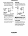
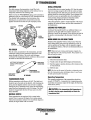
ALTERNATOR TESTING
DESCRIPTION
1. Start the Engine.
The charging system consists of an alternator with a voltage
regulator, an engine DC wiring harness, a mounted DC circuit breaker and a battery with connecting cables. Because of
the use of integrated circuits (IC's), the electronic voltage
regulator is very compact and is mounted internally or on the
back of the alternator.
2. After a few minutes of running measure the starting battery voltage at the battery terminals using a multi-meter
set on DC volts.
.
The voltage should be inc~easing toward 14 volts. If it is,
the alternator is working. Turn to Step 4
o,
( 14.0)
COM
MULTIMETER
~iS===::: #10 RED
. TO STARTER SOLENOID
#14 VIOLET
TO CHOKE
I·
TESTING THE STARTING
BATTERY· ALTERNATOR
(ENGINE RUNNING)
TROUBLESHOOTING
A WARNING: A failed alternator can become very
hot. Do not touch until the alternator has cooled down.
This troubleshooting section is to determine if a problem
exists with the charging circuit or with the alternator. If it is
determined that the alternator or voltage regulator is bad, it is
best to have a qualified technician check it out
The alternator charging circuit charges the starting battery and
the service battery. An isolator with a diode, a solenoid, or a
battery selector switch is usually mounted in the circuit to isolate the batteries so the service battery is not discharged along
with the service battery. If the alternator is charging the starting battery but not the service battery,. the problem is in the
service battery charging circuit and not with the alternator.
_
GROUND
3. If the starting battery voltage remains around 12 volts
after the engine is started and run for a few' minutes, a
problem exists with the alternator or the charging circuit.
a. Thrn off the engine. Inspect all wiring and connections.
Ensure that the battery terminals and the engine ground
connections are tight and clean.
A
CAUTION: To avoid damage to the battery.
charging circuit, never shut off the engine battery
switch when the engine is running!
b. If a battery selector switch is in the charging circuit,
ensure that it is on the correct setting.
c. Turn on the ignition switch, but do not start the engine.
d. Check the battery voltage. If your battery is in good
condition the reading should be 12 to 13 volts.
Testing the Alternator
A WARNING: Before starting the engine make certain
that everyone is clear of moving parts! Keep away from
sheaves and belts during test procedures.
(g])
0~_-.MULTIMETER
A WARNING: MULT/METERS AND DC CIRCUITS:
COM
+
;a
DC and AC circuits are often mixed together in marine
applications. Always disconnect shore power cords,
isolate DC and AC converters and shut down generators
before pedorming DC testing. No AC tests should be
made without proper knowledge of AC circuits.
TESTING THE
ALTERNATOR VOLTAGE·
(IGNITION ON - ENGINE OFF)
Engines & Generators
22
-=-
GROUND
ALTERNATOR TESTING
Alternator is Working
e. Now check the voltage between the alternator output
terminal (B+) and ground. If the circuit is good, the
voltage at the alternator should be the same as the battery, or if an isolator is in the circuit the alternator voltage will be zero. If not, a problem exists in the circuit
between the alternator and the battery. Check all the
connections - look for an opening in the charging
circuit.
4. Check the voltage of the service battery. This battery
should have a voltage between 13 and 14 volts when the
engine is running. If not, there is a problem in the service
battery charging circuit. Troubleshoot the service battery
charging circuit by checking the wiring and connections,
the solenoid, isolator, battery switch and the battery itself.
. MUlTIMETER
CHID
G
COM
TESTING THE STARTING
BATTERY - ALTERNATOR
(ENGINE RUNNING)
,.¢::=-.......
ENGINE
GROUND
SERVICE
BATTERY
f. Start the engine again. Check the voltage between the
alternator output and ground.
The voltage reading for a properly operating alternator
should be between 13.5 and 14.5 volts. If your
alternator is over- or under-charging, have it repaired at
a reliable service shop.
TESTING THE SERVICE
BATTERY (ENGINE RUNNING)
A CAUTION: When performing tests on the alterna-
NOTE: Before removing the alternator for repair, use a
voltmeter to ensure that 12 volts DC excitation is pre-
tor charging circuit do not use a high voltage tester
(i.e. Megger). You can damage the alternator diodes
sent at the EXC terminal if the previous test showed
only battery voltage at the B output terminal.
If 12 volts are not present at the EXC terminal, trace
the wiring looking for breaks and poor connections.
ALTERNATOR INSPECTION
Jump 12 V to the Exc. tenninal from a known 12V
source and operate the alternator. If the voltage output
is 13-14 volts, the alternator is o.k. Trace the cause for
12 volts not being present at the Exc. terminal.
When rebuilding the engine, the alternator should be cleaned
and inspected. The housing can be wiped off with a solvent
and the alternator tenninal studs should be cleaned with a
wire brush. Make certain the studs are tight and clean the
wiring connections that connect to the wiring harness.
Tum the rotor pulley by hand. It should tum smoothly.
Depending on when the alternator was last serviced, the
brushes may need replacing. If the alternator is at all suspect,
send it to a service shop for testing and overhaul.
Engines & Generators
23
DUAL OUTPUT ALTERNATORS
SPACER TO MOUNTING
BRACKET
DESCRIPTION
Dual output and high output alternators are available as
optional equipment on most WESTERBEKE engines. These
alternators can be installed during factory assembly or as
add-on equipment at anytime.
Dual alternators can be configured to charge two banks of
batteries at the same time or, using a battery selector switch,
charge each set of batteries separately.
TO
INSTALLATION
If an optional dual alternator has already been factory installed,
simply follow the WESTERBEKE wiring diagram and the
engine installation instructions.
If the new dual alternator is being added to an existing "inthe-boat" engine, carefully follow the alternator installation
instructions below:
1. Disconnect the alternators negative cable from the
battery.
2. Remove the alternator and disconnect or tape off the
output [positive] cable. Do not reuse.
3. Install the new alternator.
4. Attach a new heavy gauge output cable[s] from the
alternator's output terminal [s]. Using the cable sizes
indicated.
DUAL OUTPUT ALTERNATOR
[CHARGING ONE BATTERY]
UP TO.~6='_#~4 WIRE
UP TO 12'
#2 WIRE
UP TO 20'
#0 WIRE
{ALWAYS USE FINE STRAND CABLE]
-LENGTH
- - -REQUIRED
5. Make certain that the batteries negative post ground
cable to the engine block is the same heavy gauge as
the positive cable.
BATTERY 1
6. Mount the regulator to a flat surface in a cool dry
location.
a. Connect the black wire to the ground terminal on the
TO
alternator.
A CAUTION: Do not connect any power source without first grounding the regulator.
b. Plug the 2-pin connector into the alternator, make
certain it is firmly seated.
c. TIle red "battery sense" wire should be connected to
the batteries positive [+] post [or the positive cable].
------- "BATIERY SENSE"
TO BAmRY POSITIVE POST
d. The brown wire "keyed ignition" is the key circuit
which actuates the regulator, this wire must connect
to a switched [+] 12 volt source. Refer to the
WESTERBEKE WIRING DIAGRAM for the proper
connection.
~ONNECTS
.
Dual Pulleys
TO PINK AND
BLUE LEADS. THE PINK
CONNECTS TO THE
BUZZER. THE BLUE
WIRE CONNECTS TO THE
OIL PRESSURE SWITCH.
DUAL OUTPUT ALTERNATOR
[CHARGING TWO BATTERIES]
A variety of accessory pulleys for high powered and dual
charging alternators are available from your
dealer.
Engines & Generators
24
DUAL OUTPUT ALTERNATORS
TROUBLESHOOTING
Alternator Testing
NOTE: Before troubleshooting, make certain that the drive
The regulator is functioning properly and the batteries
are in good condition.
.
belts are tight and the batteries are in good condition.
1. Test the voltage at the alternator plug with the engine
off-key on. The voltage at the alternator terminal F and
the voltage in the plug [blue wire F] from the regulator
should read the same.
Regulator Testing
The red "battery sensing" wire A connects to the battery, it
must always read battery voltage. If battery voltage is not
present, trace the wire for a bad connection.
The orange wire S should read 0 volts with the key off, 12
volts [approximately] with the key on. If the readings are
incorrect, trace the wire for a bad connection.
2. Hold a screw driver close [112"] to the alternator pulley.
If voltage is present you should feel the magnetic field. If
.not, the problem may be the brushes [worn] or the rotor
[open circuit].
The blue wire F supplies current to the alternator fields, its
voltaae will vary depending on the battery charge or actual
loadl;m. The readings can vary from 4 to 12 volts with the
key on, 0 volts with the key off.
3. Start the engine, at fast idle the output terminals should
indicate 14.2 volts [no load]. A reading of 12.6 would
indic~te the alternator is not performing properly.
Apply a load such as an electric bilge pump, the voltage
should maintain at least 13.8 volts. 13 volts or less
indicates the alternator is faulty.
KEY ON - NO VOLTAGE
REGULATOR IS DEFECTIVE
KEY OFF - BAmRY VOLTAGE
REGULATDR IS DEFECTIVE
REGULATOR TEST POINTS AND PROPER VOLTAGE
Ignition On
TerminalIColor Ignition Off
2 -12 volts
I Brown
ovolts
12 volts
12.6 volts
A Red
ovolts
S Orange
ovolts
10 -11 volts
F Blue
ovolts
12 volts
All. Output
12.6 volts
NOTES:
Engine Running
14.2 volts
14.2 volts
6 - 8 volts
4 -12 volts
14.2 volts
o
When the engine is first started, it takes a few moments
for the alternator to "kick in" and take the load. There
is a noticeable change in the sound of the engine and the
RPM gauge will excite.
o
A slight whine is normal when running with a full load
on the alternator.
o
When the alternator is producing high amperage, it will
become very hot.
o
When replacing the alternator drive belts, always
purchase and replace dual belts in matched pairs.
Engines .x Generators
25
011 PRESS
ALARM
SWITCH
WATER TEMP
AI ARM.
SWITCH
W
W-70GA WIRING DIAGRAM
AL TERNA TOR
'I
1
I
1
1_ -
" 4 V 10
ALARM
SPARK PLUGS
-
-
f------,
III
1111
III
'III
III
'III
ill.L
PRESS
SWITCH
'" 'III
;
+
+tly
ULlL
I
DISTRIBUTOR
Q.lL
PRESS
SENDER
SEE
1
NOTE 3
J
TO 61..OCK
----
" 0 WHT
NEUTRAL
} SAFETY
\0.... SW ITCH
4
"4 WHT
tt
4 V 10
~========t===========~'~"~O~R~"==~~~========================t====================t==~~
r
:\4
Y
II t1
WAH R
R[O/':'iHT
I NSTRUMENT PANEl
Oil PRESSURE
WATER T€MP
TACH-HOUR METER
=-Q
~
-=-
/-,-----~~
'0'
Dr
T
TEMP
SENDER
t
BATTERY
~JI-----_
Engines & Generators
26
W·70GA WIRING SCHEMATIC
F.(SP(iN$lerLH FOP. SAFETY REGULATICllS
J.
THE wESTERB(KI:': 1!'1GI. GASOlllI( "'ARINE PRCPIJLSrON EHGUlE AS SHlfPEI'J FRvM
THE rACTOR' ANO eXClUSivE or ITS IflsrRUI~ErlT PANEL COr.cFL1(S WITH u.s.
r.OAST GUARD REGULATrON l3 CfR-r8~.
THE STAIUiARD lIiSTRUN(NT PANEL DOES
Hor N(C(SS4RILY so CQNPLY ANO IS INTENDED TO BE INSTAL-lEO ABOvE DECK
AIIO ISOLATED FRON GA.SOllNE SOuRCES 1M ACCORDANCE WITH 33t;F'A 163.410 Ibl,
2.
IT IS THE: RESPONSIBILITY OF THE BOAT MAHuFAcruREp. TO It/SuAE THAT THE
INSTALLATION OF THIS ENGINE AND ITS ,"STRUMEliT PANEL COIltPt.,Y WIYH J3CFR-r83,
). AN OH-OH SWITCH MUST BE IItSTALlED IN THIS liNE TO DISCONNECT THE STARTER
(IRCUn rROM THE BArTERl IN AN EMERGENCY AND WHEH LEAVING THE BOAT,
TwELVE vOLT STARTERS TYPICALLY DRAW lao TO !OO AMPS WHEN CRANKIfIG.
THE
OUR,uIOIi OF INDIVIDuAL CRANKING CYCLES SHOULD NOT £.XC£EO jO SECONDS. A
SWITCH WITH A COI~TlNUOUS RATING Of' 175 AMPS AT 12 VOLTS WILL NORMALLY
SERvE THESE rUNCTIONS BuT SUCH A SWITCH NUST NEVER BE uSED TO ·NA~E" THE
START(R CIRCUIT.
<4. THIS PRODuCT IS PROHeTE'O 8Y A MANUAL RESEr CIRCUIT BAEAKER LOCATED HEAR
THE STARTER AND AS CLOSE TO THE SOURcE
CURRENT AS POSSIBLE.
ExCESSIVE
CuRRENT DRAIN ANTWHERE IN THE INSTRUMENT PANEL. WIRING OR ENGINE Will
CAUSE THE BREAKER TO TRIP.
IN THIS (VENT MOST ENGINE MODELS WilL SHuT
DOWN BECAUSE THE OPENED BREAKER DI SCaNNEC T5 THE I R ruEI. SUPPL T • THEREFORE
THE BUILDER OWNER MUST 8~ SURE THAT THE INSTRUMENT PANEL WIRING AND ENGIHE
ARE INSTALLED TO PREVENT CONTACT BEiY/EEW ELE(TRICAL DEVICES ·AND SALT WATER.
or
eA TTEI{, I ( VUC
STARr
SOL.
STAIHER
i-~'-~:------~~r-------------~
I
+-____+-__
I
ALTERNATOR
~OU~T~
EXC
rG~N~O
________________~____________~
TACH
DIODE
eALLAST
RESISTOR
COl L
C.P.
SWI TCH
TACHOMETER
'-+__f-____-"{s
GliO
VOL TNETER
GNO
GND
PRESTART
SWI reM
\
' -___________- - - - - - - -....~_'_{I
S
GOA'ciG'E
GHD
Engines & Generators
27
TACHOMETER
TACHOMETER/HOUR METER
NOTE: Current model tachometers use a coarse adjustmei1t
dial to set the tachometer to the crankshaft pulley rpms. The
calibrating screw is then used for fine tuning.
The tachometerlhour meter used in propulsion engine instrument panels contains two separate electrical circuits with a
common ground. One circuit operates the hour meter and the
other the tachometer. The hour meter circuit operates on 12
volts alternator charging voltage supplied to the (+) terminal
on the back of the instrument.
WIRE
The tachometer circuit operates on AC voltage 6-8 volts, fed
fTom one of the diodes in the alternator and supplied to the
tachometer input terminal while the engine is running, and
the alternator producing battery charging voltage 13.0-14.8
volts DC.
The following are procedures to follow when troubleshooting
a fault in either of the two circuits in a tachometerlhour
meter.
TERMINAL
COARSE
ADJUSTMENT
Hour meter Inoperative
Check for the proper DC voltage between (+) and (-)
terminals.
1. Voltage present - meter is defective - repair or replace.
2. Voltage not present - trace (+) and (-) electrical connections for fault. (Jump 12 volts DC to meter (+)
terminal to verifY the operation.)
INP
AC VOLTAGE
CALIBRATION
TACHOMETER CALIBRATION &
IDLE SPEED ADJUSTMENT (New Installation)
NOTE: In a new installation (commissioning) the tachometer
in the instrument panel will not always be correctly
calibrated to the engine's RPM. The tachometers calibration
must be checked in a new installation (commissioning) ..
1. Place a piece of reflective tape on the outer edge of the
front crankshaft pulley.
Tachometer Inoperative
Check for the proper AC voltage between tachometer input
terminal and (-) terminal with the engine running.
1. Voltage present - attempt adjusting meter through calibration access hole. No results, repair or replace meter.
2. AC voltage not present - check for proper alternator DC
output voltage.
3. Check for AC voltage at tach terminal on alternator to
ground.
4. Check electrical connections from tachometer input terminal to alternator connection.
2. Start the engine and allow the engine to warm up and
then set the engine speed at a high idle 1500 rpm, using
a strobe type tachometer shooting the front crankshaft
pulleys reflective tape for an accurate engine rpm reading.
3. Positive the"coarse" adjustment at each of the six
selections. Select the one that sets the tachometer reading
closest to the 1500 rpm.
4. Using a small phillips screw driver, adjust the calibration
pod to set the tachometer exactly on 1500 rpm.
S. Check the tachometer readings at idle and at high rpm.
6. Adjust the idle speed at a comfortable rpm, but not at too
Iowa speed to induce vibration and stalling when shifting
the transmission.
Tachometer Sticking
1. Check for proper AC voltage between "tach inp." terminal and (-) terminal.
2. Check for good ground connection between meter (-)
minal and alternator.
3. Check that alternator is well grounded to engine block at
alternator pivot bolt.
Tachometer Inaccurate
a. With a hand-held tach on the front of the crankshaft
pulley retaining nut or with a strobe-type tach, read the
front crankshaft pulley rpm at idle.
h. Adjust the tachometer with a small Phillips type screwdriver through the calibration access hole in the rear of
the tachometer. Zero the tach and bling it to the rpm
indicated by the strobe or hand tach. VerifY the rpm at
idle and at high speed.
Engines & Generators
28
ENGINE ADJUSTMENTS
SPARK PLUGS
DRIVE BELT ADJUSTMENT
The spark plugs should be cleaned and regapped after the
first 50 hour break-in period, then inspected every 250 hours
thereafter and replaced as needed.
The drive belts must be properly tensioned. Excessive drive
belt tension can cause rapid wear of the belts and reduce the
service life of the bearing and the alternator, raw water pump,
and engine coolant pump. A slack belt or the presence of oil
on the belt can cause belt slipping, resulting in high operating
temperatures and the failure of the same components.
A WARNING: Do not remove the spark plugs while
the engine is hot. Allow the engine to cool before
removing them.
1. To adjust the alternator and the engine coolant belts,
loosen the alternator mounting bolts and pivot the
alternator as needed. Retighten the bolts.
2. To adjust the raw water pump belt, loosen the mounting
bolts and slide the pump up and down as needed.
Retighten the bolts.
SPARK PLUG GAP: 0.031-0.028 ± 0.0002 in. (0.8-0.7mm)
SPARK PLUG TORQUE: 10 -15Ib-H (1.5 - 2.31 kg-m)
NOTE: Loctite Anti-Seize applied to the threadedportion of
the spark plugs will retard corrosion, making fuiure removal
of the spark plugs easier.
NOTE: When the belts are loose, inspect for wear, cracks and
frayed edges, and replace if necessary.
3. The drive belts are properly adjusted if it can be deflected
no less than 3/8 inch (lOmm) and no more than 112 inch
(12mm) as the belt is depressed with the thumb at the
midpoint between the two pulleys on the longest span of
the belt.
4. Operate the engine for about 5 minutes, then shut down
the engine and recheck the belts tension.
NOTE: Maintain a 22 lb pressure to the belt's outer face for
proper belt operation. Spare belts should always be carried on board
INSPECTING
THE SPARK
PLUGS
\\......_ -'L._--INSPECT FOR
DAMAGE
A WARNING: Never attempt to check or adjust a
drive belt's tension while the engine is in operation.
CHECK FOR
CARBON AND
BURNING
Engines & Generators
29
ENGINE ADJUSTMENTS
NOTE: WESTERBEKE recommends that the following engine
adjustments be peiformed by a competent engine mechanic.
The infonnation below is provided to assist the mechanic.
VALVE CLEARANCE ADJUSTMENT
IGNITION TIMING
NOTE: Retorque the cylinder head bolts before adjusting the
1. Attach a timing light to the #1 spark plug and mark the
engine's valves (see TORQUING THE CYLINDER HEAD
BOLTS).
front crankshaft timing groove and the timing mark on the
scale embossed on the engine's front cover.
1. Remove the rocker cover and gaske~.
Each timing mark represents 2°.
2. Position the No.1 piston at Top Dead Center (IDC) of its
compression stroke and adjust the #1 and #3 exhaust
No.1 and No.2 valves on the intake side of the cylinder
head and the No.1 and No.3 on the exhaust side. Rotate
the crankshaft 360° in a clockwise direction and adjust
the remaining four valves.
/
/
/'
#1 INTAKE
CRANKSHAFT'
PULLEY
2. Start the engine and warm the engine to its nonnal
operating temperature.
3. Using the timing light, align the timing groove in the front
crankshaft pulley with the proper timing mark on the ignition timing scale embossed on the engine's front cover.
Do tillS by loosening and slowly rotating the distributor
body. Refer to the timing specifications:
TIMING SPECIFICATIONS
#4 EXHAUST
0° TOC AT 625 RPM
ELECTRIC CHOKE
3. Replace the rocker cover and the rocker cover gasket..
Rocker cover torque: 2.9-S.1Ih-ft (0.4-0.7 kg-m)
4. Adjust all values to 0.012 (0.30mm) with the engine hot.
~'.D121'."mm)
The electric choke uses a 12 volt heating element which
opens the choke automatically when the engine starts.
The choke is adjusted with the engine off and cooled. Adjust
the choke by loosening the three cover-securing screws and
rotating the cover clockwise to LEAN the choke and
counterclockwise to RICH the choke. The .choke is initially
set at the factory for an average of 700P (21°C) room
temperature. The choke may need readjustment at engine
commissioning for the ambient temperature of the area the
engine is operating in. The choke reference mark is located
on the underside of the choke cover.
SEE CARBURETOR
Engines & Generators
. 30
ENGINE ADJUSTMENTS
NOTE: WESTERBEKE recommends that the following engine adjustments be performed by a competent engine mechanic. The information
below is provided to assist the mechanic.
TORQUING THE CYLINDER HEAD BOLTS
ENGINE COMPRESSION
After the initial break-in period (approximately 50 hours), the
cylinder head bolts should be re-torqued.
If it becomes necessary to check the engines cylinder
compression, warm the engine and shut it down.
Remove the spark plugs and install a compression adapter
(screws into a plug hole) with a gauge.
Crank the engine (close off the raw water) and unplug the
ignition coil. Allow the compression gauge to reach a
maximum reading and record.
Measure the compression pressure for each cylinder. Ensure
that the pressure differential for each cylinder is within the
specifications.
Tighten the cylinder head bolts according to the sequence
shown. Make sure the engine is cold when this is done, and
loosen one head bolt one-half turn and then tighten it
between 55 - 59 lb-ft (8.2 - 8.8 Kg-rn). Then proceed to the
next head bolt in the sequence. Tighten the RS (rocker cover
stud) securely.
4
COMPRESSION PRESSURE AT 1400 RPM
198.1 psi (14 kg/em')
LIMIT OF DIFFERENCE BETWEEN CYLINDERS
28.0 psi (2.0 kg/em')
If a cylinder's compression or pressure differential is below
the limit, add a small an10unt of engine oil through the spark
plug hole and repeat the test. If the oil causes an increase of
pressure, the piston ring andlor cylinder wall may be worn or
damaged. If the added oil does not increase compression
pressure suspect poor valve contact, valve seizure, or valve
wear. Reinstall the plugs, ignition wires, and coil. Open the
raw water tbru seacock.
10
7
3
HIGH TENSION CORDS (IGNITION WIRES)
Check the ignition wires every 500 operating hours as engine
compartment heat can deteriorate the wires.
Check the resistance of each wire. Do not pull on the wire
because the wire connection inside the cap may become
separated or the insulator may be damaged. When removing
the wires from the spark plugs, grasp and twist the molded
cap, then pull the cap off the spark plug.
THE RESISTANCE VALUE IS 410 OHM PER INCH.
TESTING
RESISTANCE
Engines & Generators
31
ENGINE TROUBLESHOOTING
The following troubleshooting table describes certain problems
relating to engine service, the probable causes of these problems,
and the recommendations to overcome these problems.
When troubleshooting indicates an electrical problem, refer to
the ELECTRICAL SYSTEM WIRING DIAGRAMS.
Problem
No panel indications; fuel solenoid
or fuel pump is not working (key switch
is on and PRESTART button is depressed)
START button is depressed, no starter
engagement.
Engine cranks, but does not start.
NOTE: The engine s electrical system is protected by a 20
ampere manual reset circuit breaker located on a bracket at
the back of the engine. The preheat solenoid is mounted on
the same bracket.
Probable Cause
VerificationJRemedy
1. Battery switch not on.
1. Check switch and/or battery connections.
2. 20-amp circuit breaker tripped.
2. Reset breaker; if breaker trips again, check preheat solenoid
circuit and check circuit for shorts to ground.
3. Loose battery connections.
3. Check (+) connection to starter solenoid and (-) connection to
engine ground stud. Check battery cable connections.
1. Connection to solenoid faulty.
1. Check connection.
2. Gear shift not in neutral.
2. Gear shift must be in neutral (see NEUTRAL SWITCH under
HURTH HSW TRANSMISSIONS).
3. Faulty switch.
3. Check switch with ohmmeter.
4. Faulty starter solenoid.
4. Check that 12 volts are present at the solenoid connection.
5. Loose battery connections.
5. Check battery connections.
6. Low battery.
6. Check battery charge state.
1. Faulty fueling system.
1. Check that fuel valves are open. Check fuel supply.
1a. Check for air in fuel system. Bleed air from fuel system.
1b. Fuel filters clogged. Replace filters and bleed air from
fuel system.
2. Fuel lift pump failure.
2. Pump should be "ticking". Check connections, check for 12
volts. Replace pump.
3. Choke.
3. Check choke operation. Adjust tension.
4. Low battery power.
4. Switch to combine house and start batteries. Replace batteries.
5. Carburetor filter screen is clogged.
5. Clear with compressed air or clean with kerosene.
6. Engine is flooded.
6a. Carburetor float needle valve open or damaged. Clean or
replace the needle valve.
6b. Float in carburetor is leaking. Repair or replace float.
6c. Float chamber gasket damaged or securing screws are loose.
Replace gasket and/or tighten screws.
Poor running performance.
7. Worn or faulty spark plugs.
7. Replace.
8. High tension wires grounding.
8. Inspect wires and test.
9. Faulty ignition coil.
9. Test coil.
10. Faulty distributor.
10. Test distributor, see manual.
11. Faulty wire connection.
11. Inspect wires.
12. No engine compression.
12. test compression, see manual.
13. Faulty idle adjustment.
13. Adjust idle, see manual.
1. Carburetor inlet clogged.
1. Remove and clean.
2. Main jet clogged.
2. Remove and clean.
3. Air intake, carburetor screen dirty.
3. Remove and clean.
4. Carburetor inlet filter clogged.
4. Remove and clean.
5. Fuel lines clogged.
5. Inspect lines. replace inlet fuel filter.
(continued)
Engines & Generators
32
ENGINE TROUBLESHOOTING
Problem
Engine starts, runs
and then shuts down.
Engine starts, runs but
does not throttle up.
Engine hunts
Battery runs down.
Probable Cause
Verification/Remedy
1. Dirty fueVwater separator filter.
2. Faulty fuel lift pump.
1. Change filters.
2. Pump should be "ticking". Check connections,test for 12 volts.
1. Fuel line restriction.
1. Inspect all fuel lines.
2. Throttle plate binding.
2. Adjust linkage.
3. Faulty fuel lift pump.
3. Lift pump should "tick". Check connections, test for 12 volts.
4. Air intake restriction.
4. Check air intake. Clean/replace filter screen.
5. High exhaust back pressure.
5. Inspect exhaust elbow for corrosion. Check exhaust elbow
hose. Test back pressure.
1. Low battery voltage.
1. Check batteries.
2. Cracked distributor cap.
2. Replace distributor cap.
3. Faulty high tension wires.
3. Test wires.
4. Faulty fuel lift pump.
4. Lift pump should "tick". Check connections, test for 12 volts.
5. High exhaust back pressure.
5. Inspect exhaust elbow for corrosion. Check exhaust elbow
hose. Test back pressure.
6. Valves are out of adjustment.
6. Adjust valves.
7. Dirty fuel filters.
7. Change filters.
1. Oil pressure switch.
1. Observe if gauges and panel lights are activated when engine i
not running. Test the oil pressure switch.
2. High resistance leak to ground.
2. Check wiring. Insert sensitive (0 - .25 amp) meter in battery
lines. (Do not start engine.) Remove connections and replace
after short is located.
3. Low resistance leak.
3. Check all wires for temperature rise to locate the fault.
4. Poor battery connections.
4. Check cable connections at battery for loose connections,
5. DC altemator not charging
(tachometer not operating).
5. Check connections, check belt tension, test alternator. See
ALTERNATOR TESTING.
1. DC charge circuit faulty.
1. Perform DC voltage check of generator charging circuit. See
Testing the Battery Charging Circuit.
2. Alternator drive.
2. Check drive belt tension; alternator should turn freely. Check
corrosion
Battery not charging
for loose connections. Check output with voltmeter. Ensure 12
volts are present at the Exc. terminal.
Engine misfires.
1. Poor quality fuel.
1. Check filters for water. Change fuel.
1a. Fuel blockage.
1a. Replace inlet fuel filter, check fuel lines.
2. Incorrect timing.
2. Adjust timing.
3. Dirty flame arrester.
3. Clean with compressed air or kerosene.
4. Cracked distributor cap.
4. Replace distributor.
5. Faulty ignition wires.
5. Test, replace.
6. Spark plugs are worn.
6. Replace spark plugs.
7. High exhaust back-pressure.
7. Test back pressure.
8. Valve clearances are incorrect.
8. Check clearances.
Engines & Generators
33
ENGINE TROUBLESHOOTING
Problem
Engine backfires.
Probable Cause
Verification/Remedy
1. Spark plug wires are connected
1. Reconnect correctly.
wrong.
Engfne overheats.
Low oil pressure.
High oil pressure.
2. Incorrect tlming.
2. Adjust engine timing. See manual.
3. Engine is flooded. See Engine is .
flooded under Engine cranks but fails
to start.
3. See Engine cranks but fails to start column.
4. Dirty flame arrester.
4. Clean with compressed air or kerosene.
5. Cracked distributor cap.
5. Replace distributor.
6. High exhaust back-pressure.
6. Test back-pressure.
7. Choke is stuck closed.
7. Inspect carburetor.
1. Coolant loss.
1. Check for leaks, pressure test system.
2. Faulty raw water pump impeller.
2. Replace impeller.
3. Belts are loose or broken.
3. Tighten, check belts.
4. Faulty thermostat.
4. Replace.
5. Heat exchanger is clogged.
5. Service heat exchanger.
6. Collapsed hose.
6. Replace.
7. Faulty coolant pump.
7. Remove and replace.
8. Coolant tank or pressure cap faulty.
8. Inspect, replace.
1. Low oil level.
1. Add oil.
2. Faulty oil pressure switch, sender, gauge.
2. Test and replace.
3. Wrong SAE type oil in the engine.
3. Change oil.
4. Wrong type oil filter..
4. Change filter..
5. Relief valve is stuck.
5. Service engine.
6. Faulty oil pump/strainer.
6. Service engine.
7. Faulty engine bearings.
7. Service engine.
8. Faulty oil filter.
8. Change filter.
9. Oil is sump is slugged.
9. Service engine. Flush Sump.
1. Dirty oil or wrong SAE type oil in
1. Change oil.
the engine.
No DC charge to the
starting battery.
2. Relief valve is stuck.
2. Service engine.
1. Faulty connections to
1. Tighten and clean connections ..
battery.
2. Connections to the alternator are
2. Tighten and clean connections.
loose or faulty.
Oil leak.
3. Faulty alternator.
3. Test alternator.
1. Oil drain hose loose.
1. Tighten, replace.
2. Damaged or loose timing chain
2. Tighten, replace.
cover or rocker arm.
Engine alarm sound pulsates.
3. Loose or damaged oil pressure
switch or sender.
3. Tighten, replace.
4. Loose or damaged oil filter.
4. Tighten, replace.
5. Oil pan leaking.
5. Tighten bolts, replace pan gasket.
1. Loss of oil.
1. Check dipstick, look for oil leaks at oil filter and at
oil drain hose connection.
Engine alarm sounds continuously.
2. Oil pressure switch.
2. Replace oil pressure switch.
1. Engine coolant.
1. Check engine coolant level.
2. High temperature switch opens at .
2. Check for satisfactory operation with switch bypassed,
check with ohmmeter, replace if faulty.
too Iowa temperature.
Engines & Generators
34
ENGINE TROUBLESHOOTING
Probable Cause
Problem
Engine slows and stops.
Engine overheats/shuts down.
Verification/Remedy
1. Fuel lift pump failure.
1. Fuel lift pump should make a distinct ticking sound. Replace
pump with spare.
2. Switches and/or wiring loose
or disconnected.
2. Inspect wiring for short circuits and loose connections.
Inspect switches for proper operation.
3. Fuel starvation.
3. Check fuel supply, fuel valves, fuel lift pump.
4. 20 Amp circuit breaker tripping.
4. Check for high DC amperage draw during operation.
Ensure breaker is not overly sensitive to heat which would
cause tripping.
5. Exhaust system is restricted.
5. Check for blockage, collapsed hose, carbon buildup at
exhaust elbow.
6. Water in fuel.
6. Pump water from fuel tank(s); change filters and
bleed fuel system.
7. Air intake obstruction.
7. Check air intake.
1. Raw water not circulating.
1. Raw water pump failure. Check impeller - replace.
2. Coolant not circulating.
2. Obstruction at raw water intake or raw water filter.
2a. Thermostat - remove and test in hot water.
Replace thermostat.
2b. Loss of coolant - check hoses, hose clamps, drain plug, etc.
for leaks.
2c. Broken or loose belts - tighten/replace.
2d. Air leak in system; run engine and open the pressure cap to
bleed air. Add coolant as needed.
Exhaust smoke problems
1. Blue smoke.
1. Incorrect grade of engine oil. Oil is diluted.
1a. Crankcase is overfilled with engine oil (oil is blowing out
through the exhaust).
1b. Crankcase breather hose is clogged.
1c. Valves and/or piston rings are worn.
2. White smoke.
2. Engine is running cold.
3. Black smoke.
3. Improper grade of fuel.
3a. Fuel burn incomplete due to high back-pressure in exhaust or
insufficient air for proper combustion (check for restrictions in
exhaust system; check air intake).
3b. Dirty flame arrester.
3c. Faulty carburetor. Choke is stuck.
3d. Lack of air-check air intake and air filter. Check for proper
ventilation.
3e. Idle mixture jet too rich.
3f. Overload.
TROUBLESHOOTING COOLANT TEMPERATURE AND OIL PRESSURE GAUGES
If the gauge reading is other than what is nonnally indicated
by the gauge when the instrument panel is energized, the fIrst
step is to check for 12 volts DC between the ignition (B+)
and the Negative (B-) terminals of the gauge.
Assuming that there is 12 volts as required, leave the
instrument panel energized and perfonn the following steps:
1. Disconnect the sender wire at the gauge and see if the
gauge reads zero, which is the nonnal reading for this
situation.
2. Remove the wire attached to the sender terminal at the
sender and connect it to ground. See if the gauge reads
full scale, which is the nonnal reading for this situation.
If both of the above gauge tests are positive, the gauge is
undoubtedly OK and the problem lies either with the
conductor from the sender to the gauge or with the sender.
If either of the above gauge tests are negative, the gauge is
probably defective and should be replaced.
Assuming the gauge is OK, check the conductor from the
sender to the sender tenninal at the gauge for continuity.
Check that the engine block is connected to the ground.
Some starters have isolated ground terminals and if the
battery is connected to the starter (both plus and minus
tenninals), the ground side will not necessmily be connected
to the block.
Engines & Generators
35
ZF TRANSMISSIONS
SHIPMENT
INITIAL OPERATION
Por safety reasons, the transmission is not filled with
transmission fluid during shipment and the selector lever is
temporarily attached to the actuating shaft.
Before leaving the WESTERBEKE plant, each transmission
undergoes a test run, with Dextron III ATF transmission fluid.
The residual fluid remaining in the transmission after
draining acts as a preservative and provides protection
against corrosion for at least one year if properly stored.
Set the shifting lever to neutral position (N). Start the engine
and let it run long enough in idle to fill the cooler and hoses
with transmission fluid. Shift into gear, forward and reverse;
shifting should be smooth and positive. Direct changes from
forward to reverse are permissible since the multiple disc
clutch permits changing at high rpm including sudden
reversing at high speeds in the event of danger.
After initial operation, make a visual inspection of the output
coupling, oil cooler and hoses, and the cable connections to
the transmission.
SELECTION
LEVER
DIPSTICK
LOCKING THE PROPELLER
Locking of the propeller shaft by an additional brake is not
required: use the gear shift lever position opposite your
direction of travel for this purpose. Never put the gear shift in
the position corresponding to the direction of travel of the
boat.
~~~~'!.fJ- FILTER
ASSEMBLY
WHEN. UNDER SAIL OR BEING TOWED
Rotation of the propeller without a load, such as when the
boat is being sailed, being towed or anchored in a river, as
well as operation of the engine with the propeller stopped
(for charging the battery), will have no detrimental effects on
the transmission.
OUTPUT
COUPLING,
ZF-63
OIL COOLER
NOTE: VVhen the boat is being sailed (engine stopped), the
gear shift must be in the neutral position. The propeller is at
idle and can free-wheel.
The oil cooler, mounted above the transmission, provides
continuous cooling for the transmission fluid. Raw water
passes through the tubes of the cooler and discharges
overboard. The transmission fluid is cooled as it flows around
the tubes and back into the transmission.
WESTERBEKE RECOMMENDS
HAVING A SPARE COOLER
ABOARD
DAILY OPERATION
D Check the transmission fluid.
D Visually check the gear shift linkage and transmission.
RAW WATER
CONNECTION
D Start the engine in neutral, allowing a few minutes at idle
to warm the fluid.
D Shift into gear.
NOTE: Too low an idle speed will produce a chattering noise
from the transmission gear and damper plate. In such cases
the idle speed should be increased.
'Mi7J--- TRANSMISSION
FLUID CONNECTIONS
ZF COOLER
Operating Temperature
TRANSMISSION FLUID
The operating temperature of the transmission should not
exceed 176°P (80°C). A connection for a temperature probe
is provided. At maximum output of the engine, the fluid may
reach 220 0 P (104°C).
Pill the transmission with De),:tron III ATF. The fluid level
should be up to the mark on the dipstick. After checking the
level, press the dipstick into the case and tum it to tighten.
During the first 25 operating hours, inspect the bell housing,
output shaft and transmission cooler for leakage. The fluid
should be changed after the first 25 hours and every 300
hours thereafter.
A CAUTION: If the transmission fluid temperature is
too high, stop the engine immediately and check the
transmission fluid.
NEUTRAL SWITCH
These transmissions are equipped with a neutral safety
switch. This is to prevent the engine from starting in gear.
Unless the transmission selector lever is perfectly aligned in
neutral, the engine starter will not activate.
Engines & Generators
36
ZF TRANSMISSIONS
DESCRIPTION
NOTE: "When installing the transmission, make certain that
shifting is not impeded by restricted movability of the
Bowden cable or rod linkage, by unsuitably positioned guide
sheaves, too small a bending radius, etc. In order to mount a
support for shift control cable connections, use the two
threaded holes located above the shift cover on top of the
gear housing. Refer to the WESTERBEKE parts list.
The information below is specific to the ZF Transmissions,
the TRANSMISSION TROUBLESHOOTING SECTION
applies to all models.
CONNECTION OF GEAR BOX WITH PROPELLER
HBW recommend a flexible connection between the
transmission gearbox and the propeller shaft if the engine is
flexibly mounted, in order to compensate for angular
deflections. The installation of a special propeller thrust
bearing is not required, since the propeller thrust will be
taken by the transmission bearing, provided the value
specified under SPECIFICATIONS is not exceeded.
However, the output shaft should be protected from
additional loads. Special care should be taken to prevent
torsional vibration. When using a universal joint shaft, make
certain to observe the manufacturers instructions.
CONTROL CABLES
The transmission is suitable for single lever remote control.
Upon loosening the retaining screw, the actuating lever can
be moved to any position required for the control elements
(cable or rod linkage). Make certain that the shift lever does
not contact the actuating lever cover plate: the minimum
distanc~ between lever and cover should be O.5mm.
The control cable or rod should be arranged at right angle to
the actuating shift lever when in the neutral position. The
neutral position of the operating lever on the control console
should coincide with the neutral position of this lever.
Even with the engine solidly mounted, the use of flexible
coupling or *"DRlVESAVER" will reduce stress in the
gearbox bearings caused by hull distortions, especially in
wooden boats or where the distance between transmission
output flange and stern gland is less than about 800mm.
The shifting travel, as measured at the pivot point of the
actuating lever, between the neutral position and end
positions Aand B should be at least 35mm for the outer and
30mm for the inner pivot point.
A greater amount of shift lever travel is in no way
detrimental and is recommended. However, if the lever
travel is shorter, proper clutch engagement might be impeded
which, in turn, would mean premature wear, excessive heat
generation and clutch plate failure. This would be indicated
by slow clutch engagement or no engagement at all.
NOTE Checkfor proper lever travel at least each season.
N _
NEUTRAL
SHIFT LEVER
FORWARDS
A REVERSE
IF TRANSMISSION
CHECK FOR EQUAL TRAVEL
FROM NEUTRAL THRU
FORWARD AND REVERSE
DRAIN
A
CAUTION: The position of the mechanism behind
the actuating lever is factory-adjusted to ensure equal
shift (ever travel from neutral position A and B. If
this mechanism is in any way tampered with, the
transmission warranty will be void.
COVER PLATE
* DRlVESAVER is a product of Globe Marine, Rockland, MA.
Engines & Generators
37
MAKE CERTAIN THIS
LEVER IS TIGHTLY
FASTENED TO THE
SHAFT.
ZF TRANSMISSIONS
CABLE CONNECTIONS
SHAFT COUPLINGS
The transmission is suitable for a single lever gear shift.
Upon loosening the retaining screw, the actuating lever (see
illustration) can be moved to any position required for the
control elements (cable or rod linkage). Make certain that the
actuating lever does not contact the lever hub: the minimum
distance between the lever and the hub should be O.02in
(O.5mm).
The control cable or rod should be arranged at a ught angle
to the actuating lever when in the neutral position. The
neutral position of the gear shift lever on the control console
should coincide with the neutral position of the lever on the
transmission.
The shifting travel, as measured at the pivot point of the
actuating lever between the neutral position and end positions
A and B, should be at least I-3/8in (35mm) for the outer and
I-3116in (30mm) for the inner pivot point.
WESTERBEKE recommends a flexible connection between
the transmission and the propeller shaft if the engine is flexibly mounted, in order to compensate for angular deflections.
The installation of a special propeller thrust bearing is not
required, since the propeller thrust will be absorbed by the
transmission bearing, provided the value specified under
SPECIFICATIONS is not exceeded. However, the output
shaft should be protected from additional loads. Special care
should be taken to prevent torsional vibration. When using a
universal joint shaft, make certain to observe the manufacturer's instructions.
Even with the engine solidly mounted the use of a flexible
coupling or "DRIVESAVER" will reduce stress in the gearbox bearings caused by hull distortions, especially in wooden
boats or where the distance between the transmission output
coupling and stem gland is less than about 800mm.
NOTE: When installing the transmission, make certain that
shifting is 110t impeded by restricted movability of the cable
or rod linkage, by unsuitably positioned guide sheaves, too
small a bending radius or other r€<5trictions. In order to
111OUl2t a support for shift control cable connections, use the
two threaded lwles located on the cable bracket mounted on
the gear lwusing. Refer to the WESTERBEKE parts list.
N
For additional information contact
ZF Industries
Marine US Headquarters
3131 SW 42nd Street
Fort Lauderdale, FL 33312
Tel.: (954) 581-4040
Fax: (954)581-4077
,ACTUATING
LEVER
FOR ADDITIONAL INFORMATION
WWW.zF-MARINE.COM
A greater amount of actuating lever travel is in no way
detrimental and is recommended. However, if the lever travel
is shorter, proper clutch engagement might be impeded
which, in tum, would mean premature wear, excessive heat
generation and clutch plate failure. This would be indicated
by slow clutch engagement or no engagement at all (see
CONTROL CABLES under TRANSMISSION
TROUBLESHOOTING)
",..t---GEAR
SHIFT
TYPICAL STEERING STATION
NOTE: Checkfor proper actuating lever travel at least each
season.
A CAUTION: The position of the mechanism behind
the actuating lever is factory-adjusted to ensure equal
shift lever travel from neutral position to Aand B. If
this mechanism is in any way tampered with, the
transmission warranty will be void.
Engines & Generators
38
ZF TRANSMISSIONS
INITIAL OPERATION
OPERATING TEMPERATURE
All ZF marine transmissions are test-run on a test stand with
the engine at the factory prior to delivery. For safety reasons the fluid is drained before shipment.
Fill the gearbox with Automatic Transmission Fluid
(DEXRON II or DEXTRON ill). The fluid level should be
up to the index mark on the dipstick. To check the fluid level,
just insert the dipstick, do not screw it in. Screw the dipstick
into the case after the fluid level is checked and tighten. Do
not forget the sealing ring under the hexhead of the dipstick.
Check for leaks and change the fluid after the first 25 hours,
also make a visual inspection of the coupling, oil cooler and
hoses, and shift cables.
The maximum permissible ATF temperature should not
exceed 230° (1l00). This temperature can only be reached for
a short time.
A CAUTION: If the transmission fluid temperature is
too high; stop the engine immediately and check the
transmission fluid. .
LOCKING THE PROPELLER
Locking of the propeller shaft by an additional brake is not
required: use the gear shift lever position opposite your
direction of travel for this purpose. Never put the gear shift
in the position corresponding to the direction of travel of the
boat.
WHEN UNDER SAIL OR BEING TOWED
Rotation of the propeller without load, such as when the boat
is being sailed, being towed, or anchored in a river, as well as
operation of the engine with the propeller stopped (for
charging the battery), will have no detrimental effects on the
transmission
ZF TRANSMISSION
DAILY OPERATION
o
o
o
o
Check the transmission fluid.
Visually check the gear shift linkage and transmission.
Start the engine in neutral, allowing a few minutes at
idle to warm the fluid.
Shift into gear.
NOTE: Too Iowan idle speed will produce a chattering noise
from the transmission gear and damper plate. In such cases
the idle speed should be increased
FULL
CHECKING
FLUID
FLUID CHANGE
OPERATING
Change the fluid for the first time after about 25 hours of
operation, then every 250 operating hours 'or at least once a
year or when you change engine oil.
For additional information refer to the following text in this
Transmission Section: SHAFT COUPLINGS,
MAINTENANCE AND TRANSMISSION
TROUBLESHOOTING.
Removing the fluid
Push a suction pump hose down through the dipstick hole to
the bottom of the housing and suck out the fluid. (If space
allows, use the transmission drain). Remove the drain plug
from the bottom of the transmission and allow the fluid to
drain into a container, then reinstall the plug with its sealing
washer. Wipe down the transmission and properly dispose of
the used fluid. After running the engine, shut down and
recheck the fluid level.
Drain plug torque
ZF TRANSMISSIONS SPECIFICATIONS
20 - 25 ft/Ibs
Case-hardened helical gears, with a
servo-operated multiple disc clutch.
Gear ratio (optional)
2.63: 1 (ZF 15 MA - 3R)
2.99: 1 (ZF 15 MIV - 3R)
2.74: 1 (ZF 25 M - 3R)
ATF - type A or Dextran -1/ or 11/
ZF 15 MA 0.59 U.S. qts (0.561 liters)
ZF 15 MIV 1.11 U.S. qts (1.05 liters)
ZF 25 M
0.75 U.S. qts (0.79 liters)
Rig ht hand- Standard
TransmissiOn
Lubricating Fluid
Transmission Sump
Capacity
NOTE : When changing the fluid, take care not to lose the
drain plug sealing washer. The drain plug will leak without
this sealing washel:
A
General
Propeller Shaft
Direction of Rotation
WARNING: Never pull out the dipstick while the
engine is running. flot fluid will splash from the
dipstick hole. This could cause severe burns.
Engines & Generators
39
ZF TRANSMISSIONS
CHANGING THE TRANSMISSION FLUID
Replacing the Fluid
Pour in new Dextron III ATF fluid and check the quantity
with the dipstick.
Transmission fluid quantities will vary with the use of coolers, length of hoses and·the angle of the transmission.
Approximate Quantities
ZF 45 - 2.12 quarts (2.0 Liters)
ZF 63 - 3.2 quarts (3.0 Liters)
ZF 63V - 4.2 quarts (4.0 Liters)
Reinsert the filter assembly into the housing. Press it in place
and tighten the Allen screw.
NOTE: Some ZF transmissions use a itT" handle in place of a
screw on their filter assemblies.
16MM (8") SCREW
After running the engine, shut down and recheck the fluid level.
A WARNING: Never pullout the dipstick while the
engine is running. Hot fluid will splash from the dipstick
hole. This could cause severe burns.
MAINTENANCE
Transmission maintenance is minimal. Keep the exterior
housing clean, check the fluid level as part of your regular
routine, and change the fluid every 300 operating hours.
Periodically inspect the transmission and the cooler for leaks
and corrosion. Make certain the air vent is clear and when
checking the fluid level look for signs of water contamination
(fluid will appear as strawberry cream).
ZF·45
Lay-up/Winterize
Storage requires special care. Follow these procedures:
Drain water from the transmission oil cooler and replace
with a proper mixture of antifreeze coolant
Filter Element
o
The ZF transmission has a filter element'Iocated opposite the
dipstick. This filter must be replaced whenever the fluid is
changed.
Remove the filter by loosening the screw on the cover using
a 6mm Allen wrench.
Twist and pull out the filter and remove the element. Place
the new filter onto the cover and lock it into place by turning
it clockwise. Check the O-rings for damage and replace if
necessary. Replacement filters can be obtained from your
local WESTERBEKE dealer or ZF dealer.
NOTE: This operation will normally occur when the
engine raw water cooling system is properly winterized.
o
o
o
Removing the Fluid
Push a suction pump hose down through the pipe hole (under
the filter) to the bottom of the housing and suck out the fluid.
Remove the oil return line from the cooler and allow the oil
to drain into a container, then reconnect the oil return line.
Wipe down the transmission and properly dispose of the used
fluid.
o
Clean up the transmission and touch up unpainted areas
(use heat resistant paint).
Fill the transmission with Dextron III ATF fluid to
prevent internal corrosion (extended storage only, twelve
months or more).
Loosen attaching hardware from the transmission output
flange and propeller shaft coupling flange before .
removing the boat from the water. Separate the flanges
and spray with lubricant.
Inspect the gear shift cable, linkage, and attachments.
Look for corrosion of the end fittings, cracks or cuts in
the conduit, and bending of the actuator rods. Lubricate
all moving parts.
NOTE: If the transmission is to be storedfor a long time
(twelve l1wnths or more), it slwuld be topped offwith
fluid to prevent internal corrosion. Reduce the fluid level
before putting the engine back into service.
Engines & Generators
40
TRANSMISSION TROUBLESHOOTING [ZF]
CONTROL CABLES
The majority of transmission difficulties arise as a result of
improper clutch adjustments (manual transmissions) or
problems with control cables (hydraulic transmissions)
rather than from problems with the transmission itself.
ZF clutches, in particular, are very sensitive to improper
cable adjustments.
If you experience operating problems with the transmission,
shut the engine down. First check the transmission-fluid
level, then have a helper move the cockpit shift lever through
the fuII range - from neutral to full forward, back to
neutral, into fuIl reverse, and back to neutral - while you
observe the actuating lever on the transmission. If the remote
is stiff to operate, break the cable loose at the transmission
and try again. If it is still stiff, check the cable for kinks or
excessively tight bends, and check any linkage for binding.
Problem
Transmission gears cannot be shifted.
Fails to move into gear.
Transmission shifts into gear,
but fails to propel the boat.
Delay of gear engagement or engages
only after an increase in speed.
A new cable and perhaps a new linkage mechanism may be
needed. While the cable is loose, shift the transmission in and
out of gear using the lever on the side of the transmission to
make sure there's no binding inside the case.
If the transmission passes these tests, crank the engine and
have a helper put it in forward and reverse while you observe
the propeIIer shaft; if the shaft isn't turning, the transmission
needs professional attention. If it does tum but there's no
thrust, check to see you still have a propeller on the end of
the shaft or, if you have a folding or feathering propeller, that
it isn't stuck in the "no pitch" position.
NOTE: If you suspect a major problem in your transmission,
immediately contact your WESTERBEKE dealer or an
authorized marine transmission facility.
Probable Cause
Verification/Remedy
1. Actuating lever is loose.
1. Tighten damping bolt on shifting lever.
2. Shifting cable is broken, bent or
unattached. Cable radius is too severe.
2. Check the cable, reattach or replace.
3. Actuating lever is binding against the
3. Detach the shift cable and operate the actuating lever by
hand. Clearance should be 0.02 in (0.5mm).
1. Output coupling is not turning.
1. Transmission needs professional attention.
2. Propeller shaft is not tuming.
Output coupling is turning.
2. The coupling bolts are sheared or the coupling is Slipping
on the propeller shaft. Tighten or replace set screws, keys,
pins and coupling bolts as necessary.
3. Output coupling and
propeller shaft are turning.
3. Inspect the propeller. It may be missing or damaged.
A folding propeller may be jammed. A variable pitch
propeller may be in "no pitch" position.
1. Actuating lever travel Nto B not
1. Adjust cover plate until the lever is exact mid-position.
equal to N to A.
See ACTUATING LEVER TEXT AND DIAGRAM.
2. Actuating level travel in insufficient.
2. Check shift lever cable length. See ACTUATING LEVER
DIAGRAM.
3. Actuating lever is binding against cover plate. 3. Check clearance, adjust if necessary.
Transmission noise becomes louder.
1. Damage starting on flexible coupling due
to wear or fatigue, possibly due to
misalignment between engine and
transmission.
Chattering transmission noise,
mainly at low engine speed.
1. Check alignment, inspect flexible coupling. If noise perSists,
inspect the damper plate between the transmission and the
engine. Replace if necessary.
2. Beginning damage of bearings in
transmission due to torsional vibrations,
running without fluid, overload, wrong
alignment of transmission, or excessive
engine output.
2. Transmission needs professional attention.
1. The engine or propeller generates torsional
1. Mount a flexible coupling with another stiffness factor
vibrations in the drive unit which produces
a "chattering" noise in the transmission.
between the engine and transmission; a coupling with
a higher stiffness factor might be sufficient.
2. Inspect the damper plate between the engine and the
transmission. Replace if necessary.
Boat fails to attain specified max. speed.
Oil Leakage.
1. Operating temperature is high.
1. Wrong type of fluid. Use Dextron III, check fluid level.
2. Operating without cooling.
2. Check cooler. Inspect coolant hoses and coolant flow.
1. Corrosion at radial sealing ring and shaft.
1. Transmission needs professional attention.
Damaged sealing ring.
2. Misalignment of output flanges.
2. Check alignment. Must be within 0.003 in (0.08mm).
Engines & Generators
41
ZF TRANSMISSIONS
OPERATING TEMPERATURE
MAINTENANCE
Transmission maintenance is minimal. Keep the exterior
housing clean, check the fluid level as part of your regular
routine, and change the fluid every 300 operating hours.
Periodically inspect the transmission and the cooler for leaks
and corrosion. Make certain the air vent is clear and when
checking the fluid level look for signs of water contamination
(fluid will appear as strawbeny cream).
A CAUTION: If the transmission fluid temperature is
too high, stop the engine immediately and check the
transmission fluid.
Normal operating temperature of the transmission fluid
should be in the range of 1220 F (500 C) to 2120 F (1000 C).
A maximum temperature of 2660 F (1300 C) may be only
reached for a short time.
Make certain there is enough space around the transmission
to provide good ventilation and cooling.
Lay-up/Winlerize
Storage requires special, care. Follow these procedures:
o Drain water from the transmission oil cooler and replace
with a proper mixture of antifreeze coolant.
TRANSMISSION COOLER
NOTE: This operation will normally occur when the
engine raw water cooling system is properly winterized.
Coolers are standard equipment for the ZF 10 M, 12 M,
15 M, 15 MA, 15 MIv, and the 25 M (no cooler is necessary
for the ZF 5 M).
The cooler is a seperate part of the transmission which prevents any possibilities of coolant diluting the transmission
fluid. However, the continued flow of coolant thru the cooler
will, in time, erode the inside of the cooler causing external
o
o
o
leaks.
A transmission cooler may last ten years or more but, in
some circumstances, depending on operating hours, tropical
waters, maintemance, etc. it might only last half that time.
o
Clean up the transmission and touch up unpainted areas
(use heat resistant paint).
Fill the transmission with Dextron III ATF fluid to
prevent internal corrosion (extended storage only, twelve
months or more).
Loosen attaching hardware from the transmission output
flange and propeller shaft coupling flange before
removing the boat from the water. Separate the flanges
and spray with lubricant.
Inspect the gear shift cable, linkage, and attachments.
Look for corrosion of the end fittings, cracks or cuts in
the conduit, and bending of the actuator rods. Lubricate
all moving parts.
.
NOTE: If the transmission is to be stored for a long time
(twelve months or more), it should be topped offwith
fluid to prevent internal corrosion. Reduce the fluid level
before putting the engine back into service.
,OIL "UUILcn
For additional information contact:
IUU"""LLl INSPECT FOR
LEAKAGE AND CORROSION
ZF Industries
Marine US Headquarters
3131 SW 42nd Street
Fort Lauderdale, FL 33312
Tel.: (954) 581-4040
Fax: (954)581-4077
FOR ADDITIONAL INFORMATION
WWW.ZF-MARINE.COM
Engines & Generators
42
BORG WARNER VELVET DRIVE TRANSMISSION
SHIFT LEVER POSITION
OIL COOLER
The gear shift control mechanism and linkage must position
the actuating lever on the transmission exactly in Forward
(F), Neutral (N), and Reverse (R) shifting positions. A detent
ball located behind the transmission lever must work freely
to center the lever in each position. The gear shift positions at
the helm must be coordinated with those of the Velvet Drive
actuating lever through shift mechanism adjustments. An
improperly adjusted shift mechanism can cause damage to
the transmission. The shifting mechanism and transmission
actuating lever should be free of dirt and well lubricated to
ensure proper operation.
Shifting Into Gear
Place the gear shift in Neutral before starting the engine.
Shifting from one selector position to another selector position may be made at any time below 1000 rpm and in any
order. Shifts should be made at the lowest practical engine
speed. Start the engine and set the throttle at idle speed;
allow the transmission fluid to warm up for a few minutes.
BORG WARNER
VELVET DRIVE
SHIPMENT
Neutral
For safety reasons, the transmission is not filled with
transmission fluid during shipment and the selector lever
is temporarily attached to the actuating shaft.
Before leaving the WESTERBEKE plant, each transmission
undergoes a test run, with Dextron III ATF transmission
fluid. The residual fluid remaining in the transmission after
draining acts as a preservative and provides protection
against corrosion for at least one year if properly stored.
Move the gear shift lever to the middle position. You should
feel the detent. This centers the actuating lever on the transmission. With the control in this position, hydraulic power is
completely interrupted and the output shaft of the transmission does not turn.
NOTE: Some transmissions are equipped with a neutral safety
switch. Unless the transmission actuating lever is perfectly
aligned in neutral, the engine starter will not activate.
TRANSMISSION FLUID
Check the transmission fluid level on the dipstick. If the
transmission has not been filled, fill with Dextron III and
continue to use this fluid. During the first 25 hours of
operation, keep a lookout for any leakage at the bell housing,
output shaft and transmission cooler. This fluid should be
changed after the first 25 hours and approximately every
300 operating hours thereafter and/or at winter lay-up.
Forward
Move the gear shift lever to the forward position. You should
feel the detent. The actuating lever on the transmission is in
the forward position. The output shaft and the propeller shaft
move the boat in a forward direction.
Reverse
Move the gear shift lever to the reverse position. You should
feel the detent. The actuating lever on the transmission is in
the reverse position. The output shaft and the propeller
should move the boat in a reverse direction (astern).
A CAUTION: Be certain the transmission is filled
and the correct size cooler is properly installed before
starting the engine.
NOTE: Moving the transmission actuating lever from Neutral
Position to Forward is always toward the engine. Reverse is
always away from the engine. If boat moves backwards with
the gear shift control in the forward position, shut off the
engine! This problem may be a result of incorrect movement
of the actuating lever by the gear shift lever.
Engines & Generators
43
BORG WARNER VELVET DRIVE TRANSMISSION
F
D Clean off the transmission and properly dispose of the
N
used fluid.
N
Refill the transmission with DEXTRON III ATF. The
quantity will vary depending on the transmission model
and the installation angle. Pill through the dipstick hole.
Check the dipstick for the proper fluid level.
Replace the oil filler cap and dipstick. (press the dipstick
into place and turn clockwise until finger-tight.)
Run the engine, shutdown and recheck the fluid level.
FORWARD
NEUTRAL
REVERSE
A WARNING: Never pull out the dipstick while the
DAILY OPERATION
D
D
P
engine is running. Hot fluid will splash from the dipstick
hole. This could cause severe burns.
Check the transmission fluid.
Visually check the gear shift linkage and transmission.
Oil Capacity
Start the engine in neutral. Allow a few minutes at idle
for the fluid to warm.
Approximately 2.5 quarts (2.36 liters) will fill most transmissions to the oil level fill mark on the dipstick. Many variables
have a direct relationship to the oil capacity. Additional oil
will be required to fill the oil cooler and the cooler lines. The
angle of installation will make a difference in the quantity of
oil required to fill the transmission.
NOTE: Too low an idle speed will produce a chattering
noise from the transmission gear and damper plate. In
such cases the idle speed slwuld be increased.
D Shift into gear.
A
CAUTION: Shifting gears above 1000 rpm can
cause damage to the engine damper plate. Pulling the
throttle back to idle when shifting gears will save wear
on the transmission and the damper plate.
MAKE CERTAIN THE RUBBER SEAL IS
SCREWED
TIGHTTOTHE
HANDLE
INSPECTION
........."',
MAX
D Visually check for oil leaks at the hydraulic connections.
Check for wear on the hydraulic lines and replace if
worn.
Lubricate the detent ball and shift cable attachments.
D
D Inspect the shift linkage.
D Inspect the transmission bolts; retorque if necessary.
A
CAUTION: Clutch failure will occur if the
transmission shift lever does not fully engage the
detent ball positions.
Oil Temperature
A maximum oil temperature of 1900 P (88°C) is recommended. Discontinue operation anytime sump oil temperature exceeds 230 0 P (1 lO°C).
CHANGING THE TRANSMISSION FLUID
After the initial 50 hour change, the transmission fluid should
be changed at every 300 operating hours thereafter or at winter haul-out. However, the fluid must be changed whenever it
becomes contaminated, changes color, or smells rancid.
PRESSURE GAUGE
An optional mechanical pressure gauge can be installed at
the control panel to constantly monitor the pressure of the
transmission fluid. A normal reading at 2000 rpm in forward
gear should indicate 95 - 120 Ib-in2 (6.7 - 8.4 kg-cm2) and be
constant.
D Remove the oil filler cap and dipstick.
D Remove the oil cooler return line and allow the oil to
drain into a container.
D Reconnect the oil cooler return line.
D Use a suction pump to remove the transmission oil
through the filler cap/dipstick hole.
Engines & Generators
44
BORG WARNER VELVET DRIVE TRANSMISSION
MAINTENANCE
WARRANTY NOTES
Transmission maintenance is minimal. Keep the exterior
housing clean, check the fluid level as part of your regular
routine, and change the fluid every 300 operating hours.
Periodically inspect the transmission and the cooler for leaks
and corrosion. Make certain the air vent is clear and when
checking the fluid level look for signs of water contamination
(fluid will appear as strawberry cream).
Service manuals are available from your BORG WARNER
dealer.
For assistance, contact:
BORG WARNER
1208 Old Norris Blvd.
Liberty, SC 29657
Tel.: 800-583-4327 ext.l29
BORG WARNER is aware of the shock loads that can be
placed on its gears as the result of mechanical propeller
operation or fully reversing of the propeller blades while
shifting. Therefore torque loads and directional changes
should be made at low engine speeds. If it is found that a
failure was caused by a shock load, any warranty claim will
be denied.
Lay-up/Winterize
Storage requires special care. Follow these procedures:
Drain the water from the transmission oil cooler and
replace it with a proper mixture of antifreeze coolant.
o
NOTE: This operation will usually occur when the engine
raw water cooling system is properly winterized.
o
o
o
o
Clean up the transmission and touch-up unpainted areas
(use heat resistant paint).
Fill the transmission with Dextron III ATF fluid to the fill
mark.
Loosen attaching hardware from the transmission
output flange and propeller shaft coupling flange before
removing the boat from the water. Separate the flanges
and spray with lubricant.
Inspect the gear shift cable, linkage, and attachments.
Look for corrosion of the end fittings, cracks or cuts in
the conduit, and bending of the actuator rods. Lubricate
all moving parts.
A CAUTION: System-related noises or vibrations can
occur at low engine speeds which can cause gear rattle
resulting in damage to the engine and/or transmission.
BORG WARNER is not responsible for total systemrelated torsional vibration of this type.
If any problems occur with the transmission, see
TRANSMISSION TROUBLESHOOTING in this manual.
NOTE: If the transmission is to be stored for a long time
(twelve months or more), it should be topped offwith
fluid to prevent internal corrosion. Reduce the fluid level
before putting the engine back into service.
Engines & Generators
45
TRANSMISSION TROUBLESHOOTING
CONTROL CABLES
OIL COOLERS
The majority of transmission difficulties arise as a result of
improper clutch adjustments (manual transmissions) or problems with control cables (hydraulic transmissions) rather than
from problems with the transmission itself.
HURTH clutches, in particular, are very sensitive to improper
cable adjustments.
If you experience operating problems with the transmission,
shut the engine down. First check the transmission-oil level,
then have a helper move the cockpit shift lever through the
full range - from neutral to full forward, back to neutral,
into full reverse, and back to neutral- while you observe
the actuating lever on the transmission. If the remote is stiff
to operate, break the cable loose at the transmission and try
again. If it is still stiff, check the cable for kinks or excessively tight bends, and check any linkage for binding. A new
cable and perhaps a new linkage mechanism may be needed.
While the cable is loose, shift the transmission in and out of
gear using the lever on the side of the transmission to make
sure there's no binding inside the case.
If the transmission passes these tests, crank the engine and
have a helper put it in forward and reverse while you observe
the propeller shaft; if the shaft isn't turning, the transmission
needs professional attention. If it does turn but there's no
thrust, check to see you still have a propeller on the end of
the shaft or, if you have a folding or feathering propeller, that
it isn't stuck in the "no pitch" position.
The continued flow of raw water through the cooler will, in
time, erode the inside of the cooler causing cross leaks to
occur. These internal cooler leaks will cause one of the following two problems:
1. Transmission fluid will leak into the flow of raw water
and be discharged overboard through the engine exhaust.
A loss of transmission fluid will cause the transmission to
fail.
2. The raw water will leak into the transmission fluid causing an increase in transmission fluid. This contaminated
fluid will appear as strawberry cream. The transmission
will eventually fail.
Either case requires an immediate response:
1. Install a new oil cooler.
2. Refill the transmission with DEXTRON III ATF.
If water has contaminated the fluid, the transmission fluid
needs to be cleaned out and replaced with fresh fluid. It will
take several fluid changes to get rid of the contamination.
Check your dipstick each time until it appears as pure transmission fluid. Change the transmission filter and clean out
the fluid lines that connect to the cooler.
If the transmission fails to shift properly, it will most likely
need the attention of a qualified transmission service facility.
A transmission cooler may last ten years or more but, in
some circumstances, depending on operating hours, tropical
waters, maintenance, etc. it might only last half that time.
WESTERBEKE recommends having a spare cooler aboard
Problem
Transmission gears cannot be shifted.
Shifting pressure too low.
Transmission noise becomes loude'r.
Probable Cause
VerificationJRemedy
1. Shifting lever is loose.
1. Tighten damping bolt on shifting lever.
2. Shifting cable is broken, bent or
unattached.
2. Check the cable, reattach or replace.
3. Loss of transmission fluid.
3. Check for leaks at transmission seal and output shaft.
Tighten gear case bolts. Check all oil hoses for leaks.
Oil cooler leak - see OIL COOLER.
4. Water in transmission fluid.
4. Replace oil cooler (see OIL COOLEFf). High water in engine
compartment, remedy cause. Shifting pressure too low, see
item 2.
1. Improper fluid.
1. Replace with DEXTRON 11/ ATF.
2. Filter is dirty (if applicable).
2. Replace filter.
3. Water in transmission fluid.
3. Replace oil cooler - see OIL COOLER.
4. Transmission fluid too low.
4. Add fluid.
5. Air vent is clogged.
5. Remove paint/dirt from vent.
1. Fluid level too low,
so that pump sucks in air.
1. Top up with fluid to marking on dipstick.
2. Damage starting on flexible coupling due
to wear or fatigue, possibly due to misalignment between engine and transmission.
2. Replace flexible coupling. Check alignment between engine
and transmission.
3. Beginning damage of bearings in transmission due to torsional vibrations, running
without fluid, overload, wrong alignment of
transmission, or excessive engine output.
3. Transmission needs professional attention.
Engines & Generators
46
TRANSMISSION TROUBLESHOOTING
Problem
Probable Cause
VerificationJRemedy
Chattering transmission noise,
mainly at low engine speed.
1. The engine or propeller generates torsional
1. Mount a flexible coupling with another stiffness factor
vibrations in the drive unit which produces
a "chattering" noise in the transmission.
between the engine and transmission; a coupling with
a higher stiffness factor might be sufficient.
Transmission shifts into gear, but
fails to propel the boat.
1. Output coupling is not turning.
1. Transmission needs professional attention.
2. Propeller shaft is not turning.
Output coupling is turning.
2. The coupling bolts are sheared or the coupling is slipping
on the propeller shaft. Tighten or replace set screws, keys,
pins and coupling bolts as necessary.
3. Output coupling and
propeller shaft are turning.
3. Inspect the propeller; it may be misSing or damaged.
A folding propeller may be jammed.
Variable pitch propeller may be in "no pitch:'
NOTE: If you suspect a major problem in your transmission,
immediately contact your WESTERBEKE dealer or an authorized marine transmission/acility.
Engines & Generators
47
LAY-UP &RECOMMISSIONING
GENERAL
Fuel System [Gasoline]
Many owners rely on their boatyards to prepare their craft,
including engines and generators, for lay-up during the
off-season or for long periods of inactivity. Others prefer
to accomplish lay-up preparation themselves.
Top off your fuel tanks with unleaded gasoline of 89 octane
or higher. A fuel conditioner such as Sta-Bil gasoline
stabilizer should be added. Change. the element in your
gasoline/water separator and clean the metal bowl. Re-install
and make certain there are no leaks. Clean up any spilled
fuel.
The procedures which follow will allow you to perform your
own lay-up and recommissioning, or you may use them as a
check list if others do the procedures.
Fuel System [Diesel]
These procedures should afford your engine protection
during a lay-up and also help familiarize you with the
maintenance needs of your engine.
If you have any questions regarding lay-up procedures, call
your local servicing dealer; he will be more than willing to
provide assistance.
Top off your fuel tanks .with No.2 diesel fuel. Fuel additives
such as BioBor and Sta-Bil should be added at this time to
control algae and condition the fuel. Care should be taken
that the additives used are compatible with the primary fuel
filter/water separator used in the system. Change the element
in your primary fuel filter/water separator, if the fuel system
has one, and clean the separator sediment bowl.
Propeller Shaft Coupling [Propulsion Engine]
Change the fuel filter elements on the engine and bleed the
fuel system, as needed. Start the engine and allow it to run
for 5 - 10 minutes to make sure no air is left in the fuel
system. Check for any leaks that may have been created in
the fuel system during this servicing, correcting them as
needed. Operating the engine for 5 - 10 minutes will help
allow movement of the treated fuel through the injection
equipment on the engine.
The transmission and propeller half couplings should always
be opened up and the bolts removed when the boat is hauled
out of the water or moved from land to water, and during
storage in the cradle. The flexibility of the boat often puts a
severe strain on the propeller shaft or coupling or both, while
the boat is taken out or put in the water. In some cases, the
shaft has actually been bent by these strains. This does not
apply to small boats that are hauled out of the water when
not in use, unless they have been dry for a considerable
period of time.
Raw Water Cooling Circuit
Close the through-hull seacock. Remove the raw water intake
hose from the seacock. Place the end of this hose into a five
gallon bucket of clean fresh water. Before starting the engine,
check the zinc anode found in the primary heat exchanger on
the engine and clean or replace it as required, and also clean
any zinc debris from inside the heat exchanger where the
zinc anode is located. Clean the raw water strainer.
Start the engine and allow the raw water pump to draw the
fresh water through the ·system. When the bucket is empty,
stop the engine and refill the bucket with an antifreeze
solution slightly stronger than needed for winter freeze
protection in your area.
Fresh Water Cooling Circuit [Propulsion Engine]
A 50-50 solution of antifreeze and distilled water is
recommended for use in the coolant system at all times.
This solution may require a higher concentration of
antifreeze, depending on the area's winter climate. Check the
solution to make sure the antifreeze protection is adequate.
Should more antifreeze be needed, drain an appropriate
amount from the engine block and add a more concentrated
mixture. Operate the engine to ensure a complete circulation
and mixture of the antifreeze concentration throughout the
cooling system. Now recheck the antifreeze solution's strength.
Start the engine and allow all of this mixture to be drawn
through the raw water system. Once the bucket is empty, stop
the engine. This antifreeze mixture should protect the raw
water circuit from freezing during the winter lay-up, as well
as providing corrosion protection.
Lubrication System
With the engine warm, drain all the engine oil from the oil
sump. Remove and replace the oil filter and fill the sump
with new oil. Use the correct grade of oil. Refer to the
ENGINE LUBRICATING OIL pages in this manual for the
oil changing procedure. Run the engine and check for proper
oil pressure and make sure there are no leaks.
Remove the impeller from your raw water pump (some
antifreeze mixture will accompany it, so catch it in a bucket).
Examine the impeller. Acquire a replacement, if needed, and
a cover gasket. Do not replace the impeller (into the pump)
until recommissioning, but replace the cover and gasket.
A CAUTION: 00 not leave the engine's old engine oil
Intake Manifold and Thru-Hull Exhaust
in the sump over the lay-up period. Lubricating oil and
combustion deposits combine to produce harmful
chemicals which can reduce the life of your engine's
internal parts.
Place a clean cloth, lightly soaked in lubricating oil, in the
opening of the intake manifold to block the opening. Do not
shove the cloth out of sight. (If it is not visible at
recommissioning, and an attempt is made to start the engine,
you may need assistance of the servicing dealer. Make a
note to remove the cloth prior to start-up. The thru-hull
exhaust port can be blocked in the same manner.
Engines & Generators
48
LAY-UP &RECOMMISSIONING
Starter Motor
Spare Parts
Lubrication and cleaning of the starter drive pinion is advisable,
if access to the starter permits its easy removal. Make sure the
battery connections are shut off before attempting to remove
the starter. Take care in properly replacing any electrical
connections removed from the starter.
Lay-up time provides a good opportunity to inspect your
Westerbeke engine to see if external items such as drive belts
or coolant hoses need replacement. Check your basic spares
kit and order items not on hand, or replace those items used
during the lay-up, such as filters and zinc anodes. Refer to the
SPARE PARTS section of this manual.
Cylinder Lubrication [Diesel]
Recommissioning
If you anticipate a long lay-up period (12 months or more)
The recommissioning of your Westerbeke engine after a
seasonal lay-up generally follows the same procedures as
those described in the PREPARATIONS FOR STARTING section regarding preparation for starting and normal starts.
However, some of the lay-up procedures will need to be
counteracted before starting the engine.
WESTERBEKE recommends removing the fuel injectors for
access to the cylinders. Squirt light lubricating oil into the
cylinders to prevent the piston rings from sticking to the
cylinder walls.
Make sure you have a replacements for the injector and return
line sealing washers.
1. Remove the oil-soaked cloths from the intake manifold.
Intake Manifold [Gasoline]
2. Remove the raw water pump cover and gasket and
discard the old gasket. Install the raw water pump impeller
removed during lay-up (or a replacement, if required).
Install the raw water pump cover with a new cover gasket.
Clean the filter screen in the flame arrester, and place a clean
cloth lightly soaked in lube oil around the flame arrester to
block any opening. Also place an oil-soaked cloth in the
through-hull exhaust port, Make a note to remove cloths prior
to start-up!
3. Reinstall the batteries that were removed during the
lay-up, and reconnect the battery cables, making sure the
terminals are clean and that the connections are tight.
Check to make sure that the batteries are fully charged.
Cylinder Lubrication [Gasoline]
Spray fogging oil into the open air intake, with the flame
arrester removed, while the engine is running. The fogging oil
will stall out the engine and coat the valves, cylinders and spark
plugs for winter protection.
NOTE: The spark plugs will need to be removed for cleaning
and re-gapping at spring commissioning.
Batteries
If batteries are to be left on board during the lay-up period,
make sure that they are fully charged, and will remain that way,
to prevent them from freezing. If there is any doubt that the
batteries will not remain fully charged, or that they will be
subjected to severe environmental conditions, remove the
batteries and store them in a warmer, more compatible
environment.
A CAUTION: Wear rubber gloves, a rubber apron,
and eye protection when serviCing batteries. Lead acid
batteries emit hydrogen, a highly explosive gas, which
can be ignited by electrical arcing or a lighted
cigarette, Cigar, or pipe. Do not smoke or allow an open
name near the battery being serviced. Shut off all
electrical equipment in the vicinity to prevent electrical
arcing during servicing.
4. Remove the spark plugs, wipe clean, re-gap, and install to
proper tightness [gasoline}.
S. Check the condition of the zinc anode in the raw water
circuit and clean or replace the anode as needed. Note
that it is not necessary to flush the antifreeze/fresh water
solution from the raw water coolant system. When the
engine is put into operation, the system will self-flush in a
short period of time with no adverse affects. It is
advisable, as either an end of season or recommissioning
service, to inspect the area where the zinc is located in the
heat exchanger and clear any and all zinc debris from that
area.
A WARNING: Lead acid batteries emit hydrogen, a
highly-explosive gas, which can be ignited by electrical
arcing or a lighted Cigarette, cigar, or pipe. Do not
smoke or allow an open name near the battery being
serviced. Shut off all electrical equipment in the vicinity
to prevent electrical arcing during servicing.
Transmission [Propulsion Engine]
Check or change the fluid in the transmission as required Wipe
off grime and grease and touch up any unpainted areas. Protect
the coupling and the output flange with an anti-corrosion
coating. Check that the transmission vent is open. For
additional information, refer to the TRANSMISSION SECTION.
6. Start the engine in accordance with procedures described
in the PREPARATIONS FOR STARTING section of this
manual.
Engines & Generators
49
W-70GA GASOLINE ENGINE
SPECIFICATIONS
FUEL SYSTEM
Engine Type
Gasoline, four-cycle, four-cylinder, fresh
water-cooled, Vertical, in-line overhead valve
mechanism 66 hp@3600 rpm
Combustion Chamber
Multi-sphere type
General
Conventional carburetor type with electric fuel
pump
Fuel
Regular or unleaded gasoline with an octane
rating of 89 or better
Bore & Stroke
3.38 x 3.70 inches (86.0 x 94.0 mm)
Fuel Lift Pump
Electric-lift capacity of 6ft (18mm)
Piston Displacement
133.3 cubic inches (2.2 liters)
Fuel Consumption
6,0 U,S, GPH at 3600 rpm
Firing Order
1-3-4-2
Replaceable cartridge-screw on
Direction of Rotation
Clockwise, when viewed from the front
Fuel Filter
(on engine)
Compression Ratio
8:6:1
Air cleaner
(Flame Arrester)
Metal screen type-cleanable
Dimensions
Height:
Width:
Length:
AirFlow
(engine combustion)
140.0 cfm (3,9 cmm)
Weight
421 Ibs (190.9 kgs)
Maximum angle of
Installation
Not to exceed 14°
General
Fresh water-cooled block, thermostaticallycontrolled with heat exchanger
Maximum angle of
Operation
Not to exceed 20°
Operating Temperature
130 -150° F (55 - 66° C)
Fresh Water Pump
Centrifugal type, metal impeller, belt-driven
Raw Water Pump
Positive displacement, rubber impeller,
belt driven
System Capacity
(coolant)
9,0 qts (8.5 liters)
25.0 inches
21.2 inches
35.1 inches
(634 mm)
(538 mm)
(893 mm)
COOLING SYSTEM
TUNE-UP SPECIFICATIONS
Compression Pressure
(Limit of difference
between cylinders)
Valve Timing
198.1 psi (14 kg/cm') at 400 rpm
28.0 psi (2.0 kg/cm')
LUBRICATION SYSTEM
Intake Opens 2° BTDC
Intake Closes 53° ABDC
Exhaust Opens 57° BBDC
Exhaust Closes 2° ATDC
Valve Seat Angle
Intake 45°
Exhaust 45°
Valve Clearance
(engine warm)
Intake 0.012 inches (0.3 mm)
Exhaust 0.012 inches (0.3 mm)
Engine Timing
0° TDC at 625 rpm
Meets U.S.C.G. Regulation 33 CFR 183
IGNITION SYSTEMS
eneral
tributor
Pressure fed system
Oil Filter
Full flow, paper element, spin-on type
Sump Capacity
(not including filter)
4,0 U,S. qts (3.7 liters)
Operating Oil Pressure
(engine hot)
55-75 psi (3,8 - 5,2 kg/cm')
Oil Grade
API Specification of SJ
ELECTRICAL SYSTEM
EXHAUST EMISSIONS SYSTEMS
Emission Control
Systems
General
Battery ignition 12V negative ground.
Distributor with ignitor module and ignitor,
ignition coil, and spark plugs.
Starting Battery
12-Volt, (-) negative ground
Battery Capacity
300 - 600 Cold Cranking Amps (CCA)
Starter
12-Volt, reduction-solenoid mounted
DC Charging
12 VDC belt driven alternator
DC Amperage
Draw Cranking
175-200 arnps (cold engine)
Solid state type with signal generator and
ignitor
-k Plug Thread Size
14mm X 1.25 pitch
uretor (STD Type)
Down draft type, single barrel,
USCG approved flame arrester
Engines & Generators
50
TORQUE SPECIFICATIONS
MAJOR BOLTS AND NUTS
COMPONENT
FHB (M-KG)
COMPONENT
FHB (M-KG)
Air Cleaner Bracket... ...............................12.7 -17.4 (1.9 - 2.6)
Main Bearing Cap ....................................56.4 - 60.4 (B.4 - 9.0)
Alternator Bracket... .................................25.5 - 35.6 (3.B - 5.3)
Oil Pan .....................................................4.7 - B.O (7.0 - 12.0)
Alternator Flange Bolt... ........................... 12.7 - 20.B (1.9 - 3.1)
Oil Pressure Sender ................................9 - 13 (1.2 - 1.B)
Alternator Strap ....................................... 12.7 - 17.4 (1.9 - 2.6)
Oil Pressure Switch .................................9 - 13 (1.2 - 1.B)
Camshaft Pully Lock Bolt... .....................32.2 - 44.3 (4.B - 6.6)
Oil Pump
MB ......................................................12.7 -17.4 (1.9 - 2.6)
M10 ....................................................25.5 - 35.6 (3.B - 5.3)
Carburetor ...............................................B.O - 11.4 (1.2 - 1.7)
Connecting Rod Cap ...............................44.3 - 47.0 (6.6 - 7.0)
Oil Strainer
M6 ......................................................5.3 - B.O (B.O -12.0)
MB ......................................................10.7 - 15.4 (1.6 -2.3)
Coolant Pump .......................................... 12 -17 (1.6 - 2.4)
Coolant Pump Pulley ............................... 12 - 17 (1.6 - 2.4)
Rear Cover Assembly ..............................5.3 - B.O (8.0 -12.0)
Coolant Temperature Sender. ..................9 - 13 (1.2 - 1.B)
Rocker Shaft Assembly ...........................12.0 - 1B.1 (1.B -2.7)
Coolant Temperature Switch ...................9 - 13 (1.2 - 1.B)
Spark Plug ...............................................10.0 - 15.4 (1.5 - 2.3)
Crank Shaft Pulley ...................................22.1 - 25.5 (3.3 - 3.B)
Timing Belt Crank Pulley Bolt... ............... 120.9 -134.4 (1B.0 - 20.0)
Cylinder Head
Cold ....................................................55 - 59 (B.2 - B.B)
Hot .....................................................63 - 67 (9.5 - 10.0)
Timing Belt Cover
Upper .................................................4.7 - 6.7 (7.0 -10.0)
Lower .................................................4.7 - 6.7 (7.0 - 10.0)
Cylinder Head Cover. ...............................2.6 - 4.0 (4.0 - 6.0)
Timing Tension Lock Bolt .......................25.5 - 35.6 (3.8 - 5.3)
Drive Plate ...............................................16.1 - 1B.1 (2.4 - 2.7)
Thermostat Cover. ...................................12.7 - 20.8 (1.9 - 3.1)
Exhaust Manifold .....................................12 -17 (1.6 - 2.4)
Water Pump ............................................12 7 -17.4 (1.9 - 2.6)
Front Housing Assembly ......................... 12.7 -17-4 (1.9 - 2.6)
Intake Manifold ........................................12 -17 (1.6 - 2.4)
NOTE: Formula to convert Ft-Lbs to Nm (Newton Meters) multiply Ft-Lb x 1.356.
Engines & Generators
51
STANDARD HARDWARE
BOLT HEAD MARKINGS
Metric bolt class numbers identify bolts by their strength with 10.9 the
strongest.
Bolt strength classes are embossed on the head of each bolt.
Customary (inch) bolts are identifed by markings two to grade eight
(strongest). The marks correspond to two marks less than the actual grade,
i.e.; a grade seven bolt will display five embossed marks.
NOTES: 1. Use the torque values listed below when specific torque values are not available.
2. These torques are based on clean, dry threads. Reduce torque by 10% when engine oil is used.
3. Reduce torques by 30% or more, when threading capscrews into aluminum.
STANDARD BOLT &NUT TORQUE SPECIFICATIONS
SAE Grade 8
Torque
Ft·Lb (Nm)
Capsrew Body Size
(Inches) • (Thread)
SAE Grade 5
Torque
Ft·Lb (Nm)
114 - 20
- 28
8 (11)
10 (14)
10 (14)
5116·18
17 (23)
19 (26)
19 (26)
24 (33) •
27 (37)
31 (42)
35 (47)
34 (46)
44 (60)
49 (66)
49 (66)
55 (75)
55 (75)
70 (95)
78 (106)
75 (102)
85 (115)
85 (115)
105 (142)
120 (163)
11'0 (149)
120 (163)
120(163)
155 (210)
170 (231)
150 (203)
170 (231)
167 (226)
210 (285)
240 (325)
270 (366)
295 (400)
280 (380)
375 (508)
420 (569)
395 (536)
435 (590)
440 (597)
-14
605 (820)
675 (915)
1· 8
·14
590 (800)
660 (895)
660 (895)
910 (1234)
990 (1342)
- 24
3/8-16
- 24
7/16·14
- 20
1/2 -13
- 20
9/16 -12
-18
5/8 ·11
·18
3/4·10
·16
7/8· 9
SAE Grade 6-7
Torque
Ft-Lb (Nm)
METRIC BOLT &NUT TORQUE SPECIFICATIONS
12 (16)
14 (19)
Bolt
Dia.
Wrench Size
Grade 4.6
Ft-Lb (Nm)
Grade 4.8
Ft·Lb (Nm)
M3
M4
M5
5.5mm
7mm
8mm
0.3 (0.5)
O.B (1.1)
1.5 (2.5
0.5 (0.7)
1 (1.5)
2 (3)
1 (1.3)
2 (3)
4.5 (6)
1.5 (2)
3 (4.5)
6.5 (9)
M8
M9
M10
10mm
13mm
16 mm
3 (4)
7 (9.5)
14 (19)
4 (5.5)
10 (13)
18 (25)
7.5 (10)
18 (25)
37 (50)
11 (15)
35 (26)
55 (75)
M12
M14
M16
1Bmm
21 mm
24mm
26 (35)
37 (50)
59 (80)
33 (45)
55 (75)
85 (115)
63 (85)
103 (140)
159 (215)
97 (130)
151 (205)
232 (315)
M18
M20
M22
27mm
30mm
33mm
81 (110)
118 (160)
159(215)
118 (160)
166 (225)
225 (305)
225 (305)
321 (435)
435 (590)
321 (435)
457 (620)
620 (840)
M24
M27
M30
36mm
41 mm
46mm
203 (275)
295 (400)
402 (545)
288 (390)
417 (565)
568 (770)
553 (750)
811 (1100)
1103 (1495)
789 (1070)
1154 (1565)
1571 (2130)
M33
M36
51 mm
55mm
546 (740)
700 (950)
774 (1050)
992 (1345)
1500 (2035)
1925 (2610)
2139 (2900)
2744 (3720)
Grade 8.B • 9.B Grade 10.9
Ft-Lb (Nm)
Ft·Lb (Nm)
NOTE: Fonnu/a to convert Ft-Lhs to Nm (Newton Meters) multiply Ft-Lbs by 1.356.
SEALANTS & LUBRICANTS
GASKETS/SEALANTS
Use LIQUID TEFLON for sealing pipe plugs and fillings that connect coolant
passages. Do not use tape sealants!
Oil based PERMATEX #2 and it's HIGH TACK equivalent are excellent all
purpose sealers. They are effective in just about any joint in contact with
coolant, raw water, oil or fuel.
A light coating of OIL or LIQUID TEFLON can be used on rubber gaskets
and O-rings.
.
BOLTS & FASTENERS/ASSEMBLIES
LOCTITE hydraulic red sealant should be used on oil adapter hoses and the oil
filter assembly.
Coat both surfaces of the oil pan gasket with high temp RED SILICONE sealer.
When installing gaskets that seal around water (coolant) passages, coat both
sides with WHITE SILICONE grease.
High-copper ADHESIVE SPRAYS are useful for holding gaskets in position during assembly.
Specialized gasket sealers such as HYLOMAR work well in applications requiring non-hardening properties. HYLOMAR is particlarly effective on
copper cylinder-head gaskets as it resists fuel, oil and water.
Lightly oil head bolts and other fasteners as you assemble them. Bolts and
plugs that penetrate the water jacket should be sealed with PERMATEX #2 or
HIGH TACK.
When assembling the flywheel, coat the bolt threads with LOCTITE blue.
Anti-seize compounds and thread locking adhesives such as LOCTITE protect
threaded components yet allows them to came apart when necessary.
LOCTITE offers levels of locking according to the job.
LITHIUM based grease is waterproof, ideal for water pump bearings'and stuffing boxes.
Heavily oil all sliding and reciprocating components when assembling. Always
use clean engine oil!
Engines & Generators
52
STANDARD AND METRIC CONVERSION DATA
LENGTH-DISTANCE
Inches (in) x 25.4 = Millimeters (mm) x .0394 = Inches
Feet (ft) x .305 = Meters (m) x 3.281 = Feet
Miles x 1.609 = Kilometers (km) x .0621 = Miles
DISTANCE EQUIVALENTS
1 Degree of Latitude = 60 Nm = 111.120 km
1 Minute of Latitude = 1 Nm = 1.852 km
VOLUME
Cubic Inches (in3) x 16.387 = Cubic Centimeters x .061 =in3
Imperial Pints (IMP pt) x .568 = Liters (L) x 1.76 = IMP pt
Imperial Quarts (IMP qt) x 1.137 = Liters (L) x.88 = IMP qt
Imperial Gallons (IMP gal) x 4.546 = Liters (L) x .22 = IMP gal
Imperial Quarts (IMP qt) x 1.201 = US Quarts (US qt) x .833 = IMP qt
Imperial Gallons (IMP gal) x 1.201 = US Gallons (US gal) x .833 = IMP gal
Fluid Ounces x 29.573 = Milliliters x .034 = Ounces
US Pints (US pt) x .473 = Liters(L) x 2.113 = Pints
US Quarts (US qt) x .946 = Liters (L) x 1.057 = Quarts
US Gallons (US gal) x 3.785 = Liters (L) x .264 = Gallons
MASS-WEIGHT
Ounces (oz) x 28.35 = Grams (g) x .035 = Ounces
Pounds (Ib) x .454 = Kilograms (kg) x 2.205 = Pounds
PRESSURE
Pounds Per Sq In (psi) x 6.895 = Kilopascals (kPa) x .145 = psi
Inches of Mercury (Hg) x .4912 = psi x 2.036 = Hg
Inches of Mercury (Hg) x 3.377 = Kilopascals (kPa) x .2961 = Hg
Inches of Water (H20) x .07355 = Inches of Mercury x 13.783 = H20
Inches of Water (H20) x .03613 = psi x 27.684 = H20
Inches of Water (H20) x .248 = Kilopascals (kPa) x 4.026 = H20
TORQUE
Pounds-Force Inches (in-Ib) x .113 = Newton Meters (Nm) x 8.85 =in-Ib
Pounds-Force Feet (ft-Ib) x 1.356 = Newton Meters (Nm) x .738 =ft-Ib
VELOCITY
Miles Per Hour (MPH) x 1.609 = Kilometers Per Hour (KPH) x .621 = MPH
POWER
Horsepower (Hp) x .745 = Kilowatts (Kw) x 1.34 = MPH
FUEL CONSUMPTION
Miles Per Hour IMP (MPG) x .354 = Kilometers Per Liter (Km/L)
Kilometers Per Liter (Km/L) x 2.352 = IMP MPG
Miles Per Gallons US (MPG) x .425 = Kilometers Per Liter (Km/L)
Kilometers Per Liter (Km/L) x 2.352 =US MPG
TEMPERATURE .
Degree Fahrenheit (OF) = (DC X 1.8) + 32
Degree Celsius (DC) = (OF - 32) x .56
LIQUID WEIGHTS
Diesel Oil = 1 US gallon = 7.13 Ibs
Fresh Water = 1 US gallon = 8.33 Ibs
Gasoline = 1 US gallon = 6.1 Ibs
Salt Water = 1 US gallon = 8.56 Ibs
Engines. & Generators
53
METRIC CONVERSIONS
MILLIMETERS TO INCHES
INCHES TO MILLIMETERS
Inches
mm
1
2
3
4
5
10
25.40
50.80
76.20
101.60
127.00
254.00
mm
Inches
15
20
25
30
35
40
381.00
508.00
635.00
762.00
889.00
1016.00
mm
Inches
mm
Inches
1
2
3
4
5
10
0.0394
0.0787
0.1181
0.1575
0.1969
0.3937
15
20
25
30
35
40
0.5906
0.7874
0.9843
1.1811
1.3780
1.5748
10 MILLIMETERS = 1 CENTIMETER, 100 CENTIMETERS = 1 METER = 39.37 INCHES (3.3 FEET)
METERS TO INCHES
INCHES TO METERS
Inches
Meters
0.0254
0.0508
0.0762
0.1016
0.1270
0.1524
1
2
3
4
5
6
Meters
Inches
7
8
9
10
11
12
Meters
0.1778
0.2032
0.2286
0.2540
0.2794
0.3048
Inches
0.1
0.2
0.3
0.4
0.5
0.6
3.937
7.874
11.811
15.748
19.685
23.622
Meters
Inches
0.7
0.8
0.9
1.0
1.1
1.2
27.559
31.496
35.433
39.370
43.307
47.244
TO CONVERT METERS TO CENTIMETERS, MOVE DECIMAL POINT TWO PLACES TO THE RIGHT
METERS TO YARDS
YARDS TO METERS
Yards
Meters
Yards
Meters
Meters
Yards
Meters
1
2
3
4
5
0.91440
1.82880
2.74320
3.65760
4.57200
6
7
8
9
10
5.48640
6.40080
7.31520
8.22960
9.14400
1
2
3
4
5
1.09361
2.18723
3.28084
4.37445
5.46807
6
7
8
9
10
MOVE DECIMAL POINT FOR HIGHER VALUES -
Ib
POUNDS TO KILOGRAMS
kg
kg
Ib
1
2
3
4
5
0.454
0.907
1.361
1.814
2.268
Gallons
Liters
KILOGRAMS TO POUNDS
Ib
kg
1
2
3
4
5
2.205
4.409
6.614
8.818
11.023
GALLONS TO LITERS
1
2
3
4
5
3.79
7.57
11.36
15.14
18.93
1
2
3
4
5
Liters
0.47
0.95
1.42
1.89
2.37
6
7
8
9
10
Ib
13.228
15.432
17.637
19.842
22.046
LITERS TO GALLONS
Gallons
Liters
Liters
Gallons
10
20
30
40
50
37.86
75.71
113.57
151.42
189.28
1
2
5
10
20
0.26
0.53
1.32
2.64
5.28
Liters
60
90
120
150
180
Gallons
15.66
23.77
31.32
39.62
47.54
LITERS TO PINTS
PINTS TO LITERS
Pints
6.56168
7.65529
8.74891
9.84252
10.93614
e.g. 6,000 METERS = 6,561.68 YARDS
kg
2.722
3.175
3.629
4.082
4.536
6
7
8
9
10
Yards
Pints
Liters
Liters
Pints
Liters
6
7
8
9
10
2.84
3.31
3.79
4.26
4.73
1
2
3
4
5
2.11
4.23
6.34
8.45
10.57
6
7
8
9
10
Pints
12.68
14.79
16.91
19.02
21.13
TEMPERATURE
32
I
I
0
40
I
I
5
50
I
I
10
60
I
I
15
70
I
I
20
75
I
I
25
85
I
I
30
95
I
I
35
105 140
I
I
I
I
40 60
Engines & Generators
54
175 212
I
I
I
I
80 100
of
°C
SUGGESTED SPARE PARTS
WESTERBEKE MARINE GASOLINE ENGINES
CONTACT YOUR WESTERBEKE DEALER FOR SUGGESTIONS AND ADDITIONAL INFORMATION
DISTRIBUTER CAP
AND WIRES
HARDWARE KIT
WESTERBEKE RECOMMENDS CARRYING ENOUGH SPARE
ENGINE OIL (YOUR BRAND) FOR AN OIL CHANGE (5 DTS.)
AND A GALLON OF PREMIXED COOLANT.
INA CANVAS
~--------.CARR~NGBAG-----------------------------------------------
MOLDED
HOSE KIT
.SPARE PARTS KITS
WESTERBEKE also offers two Spare Pmts Kits,
each packaged in a rugged, rust free toolb()x.
KIT A includes the basic spares.
KIT B is for more extensive off-shore cruising.
KIT B
Impeller Kit
Water Pump Repair Kit
KIT A
Thermostat Kit
Impeller Kit
Zinc Anodes
Complete Gasket Kit .
Heat Exchanger Gasket
Heat Exchanger Gasket
Oil Filter
Drive Belt
Zinc Anodes
Oil Filter
Drive Belt
Spark Plugs
Spark Plugs
Engines & Generators
55
Engines & Generators
WM/DW1081-5/04