1
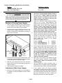
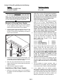
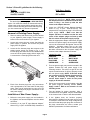
®
ENGINEERING COMPANY INC.
51 Winthrop Road
Installation Guide:
Chester, Connecticut 06412-0684
EB6 Power Supply Kit Retro-fit
Phone: (860) 526-9504
Edge® Mmodel(s) 9004SL, 9004WB, 9801,
Fax: (860) 526-4078
9802, 9804, 9806, Mini Edge®, 9104, 9206,
Internet: www.whelen.com
9206WB, 9308, 9308WB, 9000FM
Sales e-mail: [email protected]
Canadian Sales e-mail: [email protected]
Customer Service e-mail: [email protected]
Safety First
Automotive: Lightbars
This document provides all the necessary information to allow your Whelen product to be properly and safely installed.
Before beginning the installation and/or operation of your new product, the installation technician and operator must
read this manual completely. Important information is contained herein that could prevent serious injury or damage.
•
Proper installation of this product requires the installer to have a good understanding of automotive electronics,
systems and procedures.
•
If mounting this product requires drilling holes, the installer MUST be sure that no vehicle components or other
vital parts could be damaged by the drilling process. Check both sides of the mounting surface before drilling
begins. Also de-burr any holes and remove any metal shards or remnants. Install grommets into all wire
passage holes.
•
If this manual states that this product may be mounted with suction cups, magnets, tape or Velcro®, clean the
mounting surface with a 50/50 mix of isopropyl alcohol and water and dry thoroughly.
•
Do not install this product or route any wires in the deployment area of your air bag. Equipment mounted or
located in the air bag deployment area will damage or reduce the effectiveness of the air bag, or become a
projectile that could cause serious personal injury or death. Refer to your vehicle owner’s manual for the air bag
deployment area. The User/Installer assumes full responsibility to determine proper mounting location, based
on providing ultimate safety to all passengers inside the vehicle.
•
For this product to operate at optimum efficiency, a good electrical connection to chassis ground must be
made. The recommended procedure requires the product ground wire to be connected directly to the NEGATIVE
(-) battery post.
•
If this product uses a remote device to activate or control this product, make sure that this control is located in
an area that allows both the vehicle and the control to be operated safely in any driving condition.
•
Do not attempt to activate or control this device in a hazardous driving situation.
•
This product contains either strobe light(s), halogen light(s), high-intensity LEDs or a combination of these
lights. Do not stare directly into these lights. Momentary blindness and/or eye damage could result.
•
Use only soap and water to clean the outer lens. Use of other chemicals could result in premature lens cracking
(crazing) and discoloration. Lenses in this condition have significantly reduced effectiveness and should be
replaced immediately. Inspect and operate this product regularly to confirm its proper operation and mounting
condition. Do not use a pressure washer to clean this product.
•
It is recommended that these instructions be stored in a safe place and referred to when performing
maintenance and/or reinstallation of this product.
•
FAILURE TO FOLLOW THESE SAFETY PRECAUTIONS AND INSTRUCTIONS COULD RESULT IN DAMAGE TO
THE PRODUCT OR VEHICLE AND/OR SERIOUS INJURY TO YOU AND YOUR PASSENGERS!
For warranty information regarding this product, visit www.whelen.com/warranty
©1997 Whelen Engineering Company Inc.
Form No.13216B (060707)
Page 1
Table of Contents
Retro-Fit guidelines for models (with a ZF or 1ZF Power Supply):
9004SL, 9004WB, 9801, 9802, 9804, 9806, Mini Edge® ....................................page 3
Retro-Fit guidelines for models (with a ZF or 1ZF Power Supply):
9104, 9206, 9206WB, 9308, 9308WB, 9000FM ...................................................page 4
Retro-Fit guidelines for models (with a 5ZF or ZFM Power Supply):
9104, 9206, 9206WB, 9308, 9308WB, 9000FM ...................................................page 5
Retro-Fit guidelines for models (with a ZFO, 1ZFO or 2ZFO Power Supply):
9104, 9206, 9308, 9000FM, 9206WB ...................................................................page 6
EB6 Power Supply and Adaptor Harness Information ...................................................page 7
EB6 Specification Table ....................................................................................................page 7
Adaptor Cable Usage Table ..............................................................................................page 7
Page 2
Section 1; Retro-Fit guidelines for the following:
Models:
9004SL, 9004WB, 9801, 9802,
9804, 9806, Mini Edge®
With Power Supply:
ZF or 1ZF
WARNING!!!
2.
Locate the “ZF Input Harness Adaptor” shown in
Fig. 2 (P/N - 46-0741909-00). Install the 8 position
end onto Plug 1. NOTE - Make sure that the
adaptor harness is installed so that the wire
colors in Plug 1 are lined up with the wire
colors in the adaptor harness.
3.
Locate the “2ZFO/ZF Output Harness Adaptor”
shown in Fig. 2 (P/N - 46-0741908-00). This
adaptor will be connected to plugs 2 & 3 of the new
power supply. As the ends of this adaptor are
identical, it doesn’t matter which end is plugged
into the power supply. NOTE - Make sure that the
adaptor harness is installed so that the wire
colors of the adaptor plugs are lined up with
the wire colors of the power supply’s plugs.
4.
With the appropriate adaptor harnesses plugged
onto the new power supply, the new power supply
can now be connected to the lightbar. Locate the
harness plugs that were connected to the old
power supply and connect to the adaptor
harnesses as follows:
The strobe light power supply is a HIGH VOLTAGE
device. You must wait at least 10 minutes after turning
off the power to the system before starting any diagnostic or trouble shooting procedures that may bring
you into contact with any internal components.
Removal of Existing Power Supply...
1.
Remove endcap and lenses until you have access
to your lightbar’s power supply. Power supply is
located in the center section of your lightbar.
2.
Locate the three harness plugs that connect to the
existing power supply. As shown in Fig.1, the
function of each plug is indicated by the outlet to
which it was connected.
Fig. 1
Connect POWER
Connect REAR MODULES
Connect FRONT MODULES
The new power supply may now be mounted in the
lightbar. Position the new power supply in its
mounting location. This will be a tight fit and will
require a small amount of effort to properly mount
the new power supply. NOTE: If harness wraps
are present on the old lightbar plug harnesses,
it may be necessary to carefully cut and
remove these wraps in order for the power
supply to fit into the extrusion.
6.
Secure the power supply to the lightbar using the
old power supply’s mounting screws. NOTE:
Apply Loctite™ #242 to the threads of each
mounting screw.
7.
Test the lightbar for proper operation. After a
successful test, the lightbar may be reassembled
in the reverse order in which it was disassembled.
8.
If the lightbar does not function properly,
disconnect the lightbar from its power source, wait
10 minutes to avoid the risk of a high voltage shock
and confirm that the proper plugs are connected. If
the plugs connections are correct, contact your
Whelen representative for further assistance.
Input
Control
Label each of the three plugs by their function. This
is important, as this will determine how these plugs
are connected to the new power supply.
4.
With the plugs disconnected from the old power
supply, remove the two screws that hold the power
supply in position.
5.
Remove power supply from lightbar.
Installation of New Power Supply...
1.
PLUG 1
PLUG 2
PLUG 3
5.
Rear
Modules
Front
Modules
3.
to
to
to
Before the new power supply can be installed in
the lightbar, two harness adaptors must be added
as follows.
Page 3
Section 2; Retro-Fit guidelines for the following:
Models:
9104, 9206, 9206WB, 9308,
99308WB, 9000FM
With Power Supply:
ZF or 1ZF
WARNING!!!
2.
Locate the “6 to 8 pin ZF Input Harness Adaptor”
shown in Fig. 2 (P/N - 46-0745815-00). Install the 8
position end onto Plug 1. NOTE - Make sure that
the adaptor harness is installed so that the wire
colors in Plug 1 are lined up with the wire
colors in the adaptor harness.
3.
Locate the “2ZFO/ZF Output Harness Adaptor”
shown in Fig. 2 (P/N - 46-0741908-00). This
adaptor will be connected to plugs 2 & 3 of the new
power supply. As the ends of this adaptor are
identical, it doesn’t matter which end is plugged
into the power supply. NOTE - Make sure that the
adaptor harness is installed so that the wire
colors of the adaptor plugs are lined up with
the wire colors of the power supply’s plugs.
4.
With the appropriate adaptor harnesses plugged
onto the new power supply, the new power supply
can now be connected to the lightbar. Locate the
harness plugs that were connected to the old
power supply and connect to the adaptor
harnesses as follows:
The strobe light power supply is a HIGH VOLTAGE
device. You must wait at least 10 minutes after turning
off the power to the system before starting any diagnostic or trouble shooting procedures that may bring
you into contact with any internal components.
Removal of Existing Power Supply...
1.
Remove endcap and lenses until you have access
to your lightbar’s power supply. Power supply is
located in the center section of your lightbar.
2.
Locate the three harness plugs that connect to the
existing power supply. As shown in Fig. 1, the
function of each plug is indicated by the outlet to
which it was connected.
Fig. 1
Connect POWER
Connect REAR MODULES
Connect FRONT MODULES
The new power supply may now be mounted in the
lightbar. Position the new power supply in its
mounting location. This will be a tight fit and will
require a small amount of effort to properly mount
the new power supply. NOTE: If harness wraps
are present on the old lightbar plug harnesses,
it may be necessary to carefully cut and
remove these wraps in order for the power
supply to fit into the extrusion.
6.
Secure the power supply to the lightbar using the
old power supply mounting screws. NOTE: Apply
Loctite™ #242 to the threads of each mounting
screw.
7.
Test the lightbar for proper operation. After a
successful test, the lightbar may be reassembled
in the reverse order in which it was disassembled.
8.
If the lightbar does not function properly,
disconnect the lightbar from its power source, wait
10 minutes to avoid the risk of a high voltage shock
and confirm that the proper plugs are connected. If
the plugs connections are correct, contact your
Whelen representative for further assistance.
Input
Control
3.
Label each of the three plugs by their function. This
is important, as this will determine how these plugs
are connected to the new power supply.
4.
With the plugs disconnected from the old power
supply, remove the two screws that hold the power
supply in position.
5.
Remove power supply from lightbar.
Installation of New Power Supply...
1.
PLUG 1
PLUG 2
PLUG 3
5.
Rear
Modules
Front
Modules
to
to
to
Before the new power supply can be installed in
the lightbar, two harness adaptors must be added
as follows.
Page 4
Section 3; Retro-Fit guidelines for the following:
Models:
9104, 9206, 9206WB, 9308,
9308WB, 9000FM
With Power Supply:
5ZF or ZFM
position end onto Plug 1. NOTE - Make sure that
the adaptor harness is installed so that the wire
colors in Plug 1 are lined up with the wire
colors in the adaptor harness.
WARNING!!!
The strobe light power supply is a HIGH VOLTAGE
device. You must wait at least 10 minutes after turning
off the power to the system before starting any diagnostic or trouble shooting procedures that may bring
you into contact with any internal components.
3.
Locate the “2ZFO/ZF Output Harness Adaptor”
shown in Fig. 2 (P/N - 46-0745715-00). This
adaptor will be connected to plugs 2 & 3 of the new
power supply. NOTE - Make sure that the
adaptor harness is installed so that the wire
colors of the adaptor plugs are lined up with
the wire colors of the power supply’s plugs.
4.
With the appropriate adaptor harnesses plugged
onto the new power supply, the new power supply
can now be connected to the lightbar. Connect the
lightbar’s 6-position power plug to the input
harness adaptor. Now locate the harness plugs
that were connected to the old power supply and
connect to the adaptor harness as follows:
Removal of Existing Power Supply...
1.
Remove endcap and lenses until you have access
to your lightbar’s power supply. Power supply is
located in the center section of your lightbar.
2.
Locate and remove the two screws that hold the
power supply in position and remove the power
supply from the lightbar.
3.
Locate the five harness plugs that connect to the
existing power supply. As shown in Fig. 1, four
function plugs are connected to color-labled outlets
at one end of the power supply, while a larger plug
is connected to a fused plug at the other end.
4.
Each of the function plugs has a key wire whose
color corresponds to the color label for that plug’s
outlet. Take note of each plugs key color, as it will
be used to identify that plug for connection to the
new power supply.
Lightbar Plug with:
RED WIRE
WHITE WIRE
BLUE WIRE
GREEN WIRE
Before the new power supply can be installed in
the lightbar, two harness adaptors must be added
as follows.
2.
Locate the “6 to 8 pin ZF Input Harness Adaptor”
shown in Fig. 2 (P/N - 46-0745815-00). Install the 8
to
to
to
to
RED WIRE
WHITE WIRE
BLUE WIRE
GREEN WIRE
5.
The new power supply may now be mounted in the
lightbar. Position the new power supply in its
mounting location. This will be a tight fit and will
require a small amount of effort to properly mount
the new power supply. NOTE: If harness wraps
are present on the old lightbar plug harnesses,
it may be necessary to carefully cut and
remove these wraps in order for the power
supply to fit into the extrusion.
6.
Secure the power supply to the lightbar using the
old power supply’s mounting screws. NOTE:
Apply Loctite™ #242 to the threads of each
mounting screw.
7.
Test the lightbar for proper operation. After a
successful test, the lightbar may be reassembled
in the reverse order in which it was disassembled.
8.
If the lightbar does not function properly,
disconnect the lightbar from its power source, wait
10 minutes to avoid the risk of a high voltage shock
and confirm that the proper plugs are connected. If
the plugs connections are correct, contact your
Whelen representative for further assistance.
Installation of New Power Supply...
1.
Adaptor Plug with:
Page 5
Section 4; Retro-Fit guidelines for the following:
Models:
9104, 9206, 9308,
9000FM, 9206WB
With Power Supply:
ZFO, 1ZFO or 2ZFO
Installation of new Power Supply...
WARNING!!!
The strobe light power supply is a HIGH VOLTAGE
device. You must wait at least 10 minutes after turning
off the power to the system before starting any diagnostic or trouble shooting procedures that may bring
you into contact with any internal components.
1.
The new power supply is connected to the lightbar
without any adaptor cables. When connecting the
lightbar plugs to the new power supply, make sure
that the wire colors match exactly.
2.
The new power supply may now be mounted in the
lightbar. Position the new power supply in its
mounting location. This may be a tight fit and could
require a small amount of effort to properly mount
the new power supply. NOTE: If harness wraps
are present on the old lightbar plug harnesses,
it may be necessary to carefully cut and
remove these wraps in order for the power
supply to fit into the extrusion.
3.
Secure the power supply to the lightbar using the
old power supply’s mounting screws. NOTE:
Apply Loctite™ #242 to the threads of each
mounting screw.
4.
Test the lightbar for proper operation. After a
successful test, the lightbar may be reassembled
in the reverse order in which it was disassembled.
5.
If the lightbar does not function properly,
disconnect the lightbar from its power source, wait
10 minutes to avoid the risk of a high voltage shock
and confirm that the proper plugs are connected. If
the plugs connections are correct, contact your
Whelen representative for further assistance.
Removal of Existing Power Supply...
1.
Remove endcap and lenses until you have access
to your lightbar’s power supply. Power supply is
located in the center section of your lightbar.
2.
Locate and remove the two screws that hold the
power supply in position and remove the power
supply from the lightbar.
Fig. 1
3.
Locate the three harness plugs that connect to the
existing power supply. Before disconnecting these
plugs from the power supply, write down each of
the the wire colors that were connected to each
plug. This is important, as this will determine how
these plugs are connected to the new power
supply.
4.
Remove power supply from lightbar.
Page 6
SPECIFICATIONS
INPUT VOLTAGE
- 13.5 VDC ±20%
INPUT CURRENT OFF
INPUT CURRENT 30 WATTS
INPUT CURRENT 60 WATTS
INPUT CURRENT 90 WATTS
- 0 AMPS
- 3 AMPS (TYP)
- 6 AMPS (TYP)
- 9 AMPS (TYP)
FLASHRATE (CometFlash®)
FLASHRATE (DOUBLEFLASH)
FLASHRATE (SINGLEFLASH)
FLASHRATE (SEQUENTIAL)
- 75 FPM (PER LAMP) @ 85 ms
- 110 FPM (PER LAMP) @ 100 ms
- 240 FPM (PER LAMP)
- 3 CYCLES (COMET) > 4 CYCLES (SF)
INPUT CONTROL VOLTAGE
INPUT CONTROL CURRENT
- 13.5 VDC ±20%
- 50 MA (TYP)
ENERGY 30 WATT MODE
ENERGY 60 WATT MODE
ENERGY 90 WATT MODE
ENERGY LO POWER MODE
- 12.5 JOULES (TOTAL) 5/2.5/2.5/2.5 JOULES
- 26.5 JOULES (TOTAL) 11.5/5/5/5 JOULES
- 36 JOULES (TOTAL) 15/7/7/7 JOULES
- 10 JOULES (TOTAL) 2.5/2.5/2.5/2.5 JOULES
IF YOU HAVE
LIGHTBAR #:
WITH
POWER
SUPPLY #:
USE
ADAPTOR
CABLES:
9004SL, 9004WB, 9801,
9802, 9804, 9806,
Mini Edge®
ZF, 1ZF
46-0741909-00
46-0741908-00
9104, 9206, 9206WB,
9308, 9308WB, 9000FM
ZF, 1ZF
46-0741908-00
46-0745815-00
9104, 9206, 9206WB,
9308, 9308WB, 9000FM
5ZF, ZFM
46-0745715-00
46-0745815-00
9104, 9206, 9308,
9000FM, 9206WB
ZFO, 1ZFO,
2ZFO
NONE
Plug 1:
Input Control
PIN #
COLOR
FUNCTION
CONTROL
1
2
BLUE
VIOLET
P2 & P4 ENABLE
LOW POWER
3
4
5
6
7
8
GREEN
GREY
RED
BLACK
BROWN
WHITE
P3 ENABLE
TURBO
INPUT VOLTAGE
GROUND
PATTERN 1
PATTERN 2
13.5 VDC 20%
GROUND - HI POWER
N/C
- LO POWER
13.5 VDC 20%
13.5 VDC 20%
13.5 VDC 20%
GROUND
13.5 VDC 20%
13.5 VDC 20%
Fig. 2
Plug 2:
Front Modules
PIN #
COLOR
1
2
3
4
5
6
ORANGE
ORANGE
BLACK/WHITE
BLACK/WHITE
GREEN
WHITE
FUNCTION
ANODE
ANODE
CATHODE
CATHODE
TRIGGER
TRIGGER
Plug 3:
Rear Modules
PIN #
COLOR
1
2
3
4
5
6
ORANGE
ORANGE
BLACK/WHITE
BLACK/WHITE
BLUE
RED
ZF or 1ZF HARNESS ADAPTER
P/N : 46-0741908-00
FUNCTION
ANODE
ANODE
CATHODE
CATHODE
TRIGGER
TRIGGER
Plug 4:
Aux Modules
PIN #
COLOR
1
2
3
4
5
6
ORANGE
ORANGE
BLACK/WHITE
BLACK/WHITE
VIOLET
GREY
FUNCTION
ZFM or 5ZF
HARNESS ADAPTER
P/N : 46-0745715-00
ANODE
ANODE
CATHODE
CATHODE
TRIGGER
TRIGGER
Plug 2
(Front Modules/
Green Wire)
Plug 3
(Rear Modules/
Blue Wire)
Plug 4
(Not Used)
ZF INPUT HARNESS ADAPTER
(MINI & SL)
P/N : 46-0741909-00
Plug 1
(Input Control)
6 TO 8 PIN ZF INPUT HARNESS ADAPTOR
P/N : 46-0745815-00
Page 7