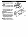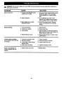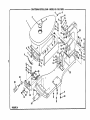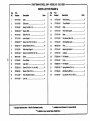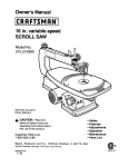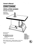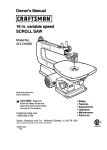
1
Owner's Manual
II:RRFTSMRN'I
24 in. 2 speed SCROLL SAW
Model No.
315.216230
\
Save this manual for
future reference.
A_, CAUTION:
Read and
follow all Safety Rules and
Operating Instructionsbefore
first use of this product.
• Safety
• Features
• Adjustments
• Operation
• Maintenance
• Parts List
Customer Help Line
1-800-932-3188
Sears,
Roebuck
and Co., Hoffman
Estates,
IL 60179
USA
Visit the Craftsman web page: www.sears.com/craftsman
972000-527
11-98
NRTL/C
Table of Contents ...........................................................................................................................................
2
Warranty and Introduction ..............................................................................................................................
2
Rules For Safe Operation ........................... :.............................................................................................
3-5
+
Electrical .........................................................................................................................................................
6
•
Glossary and Product Specifications .............................................................................................
_............... 7
•
Unpacking and Tools Needed ........................................................................................................................
•
Labels ........................................................................................................................................................
8.9
•
Features ..................................................................................................................................................
10-11
•
Assembly .................................................................................................................................................
11-12
•
Adjustments ..................................................................
12-15
•
Operation .................................................................................................................................................
•
Maintenance .................................................................
•
Troubleshooting
•
Exploded View and Repair Parts List ......................................................................................................
•
Parts Ordering / Service ...............................................................................................................................
:..........................................................................
_...............................................................................
............................................................................................................................................
FULL ONE YEAR WARRANTY
8
16-18
19
20
22-27
28
ON CRAFTSMAN SCROLL SAW
If this CRAFTSMAN" Scroll Saw fails due to a defect in material or workmanship within one year from the date of
purchase, Sears will repair it, free of charge.
Contact a Sears Service Center for repair.
If this product is used for commercial or rental purposes, this warranty applies only for 90 days from the date of
purchase.
This warranty gives you specific legal rights, and you may also have other rights which vary from state to state.
Sears, Roebuck and Co., Dept. 817WA, Hoffman Estates, IL 60179
Your saw has many features for making cutting
operations more pleasant and enjoyable. Safety,
performance and dependability have been given top
priority in the design of this saw making it easy to
maintain and operate.
_1,
_k
Look for this symbol
safety is involved.
to point
,_
out important
CAUTION: Carefully read through this entire
owner's manual before using your new saw. Pay
close attention to the Rules For Safe Operation,
and all Safety Alert Symbols including Danger,
Warning and Caution. If you use your saw
properly and only for what it is intended, you will
enjoy years of safe, reliable service.
safety precautions.
It means
attention!!!
Your
WARNING:
The operation of any power tool can result in foreign objects being thrown into your eyes,
which can result in severe eye damage. Before beginning power tool operation, always wear
safety goggles or safety glasses with side shields and a full face shield when needed. We
recommend Wide Vision Safety Mask for use over eyeglasses or standard safety glasses
with side shields, available at Sears Retail Stores.
2
The purpose of safety symbols is to attract your attention to possible dangers. The safety symbols, and
the explanations
with them, deserve your careful attention and understanding. The safety warnings do
not by themselves eliminate any danger. The instructions or warnings they give are not substitutes for
proper accident prevention measures.
MEANING
SYMBOL
&
SAFETY
ALERT
SYMBOL:
Indicates danger, warning or caution. May be used in conjunction with other symbols or pictographs.
A
DANGER: Failure to obey a safety warning will result in serious injury to yourself or to others.
Always follow the safety precautions to reduce the risk of fire, electric shock and personal injury.
A
WARNING:
Failure to obey a safety warning can result in serious injury to yourself or to others.
Always follow the safety precautions to reduce the risk of fire, electric shock and personal injury.
A
CAUTION: Failure to obey a safety waming may result in property damage or personal injury to
yourself or to others. Always follow the safety precautions to reduce the risk of fire, electric shock
and personal injury.
Note:
Advises you of information or instructionsvital to the operation or maintenance of the equipment.
IMPORTANT
Servicing requires extreme care and knowledge of the system and should be performed only by a qualified
service technician. For service we suggest you return the tool to your nearest Sears store for repair. Always use
original factory replacement parts when servicing.
_1= WARNING:
Do not attempt to operate this tool
until you have read thoroughly and understand
completely all instructions, safety rules, etc.
contained in this manual. Failure to comply can
result in accidents involving fire, electric shock,
or serious personal injury. Save owner's manual
and review frequently for continuing safe
operation, and instructing others who may use
this tool.
,_
WARNING:
Do not connect your scroll saw to a
power soume until you have assembled and
adjusted the saw as described in this manual
and have read and understood all precautions
and operating instructions in the manual and
printed on the tool.
READ
M
•
•
ALL
B
REMOVE ADJUSTING KEYS AND
WRENCHES. Get in the habit of checking to see
that hex keys and adjusting wrenches are
removed from tool before turning on the saw.
M
KEEP THE WORK AREA CLEAN. Cluttered
work areas and work benches invite accidents.
DO NOT leave tools or pieces of wood on the
saw while it is in operation.
M
DO NOT USE IN DANGEROUS ENVIRONMENTS. Do not use power tools near gasoline or
other flammable liquids, in damp or wet locations, or expose them to rain. Keep the work
area we, lit.
•
KEEP CHILDREN AND VISITORS AWAY. All
visitors should wear safety glasses and be kept a
safe distance from work area. Do not let visitors
contact tool or extension cord while operating.
•
MAKE WORKSHOP CHILD-PROOF with
padlocks and master switches or by removing
starter keys.
•
DO NOT FORCE THE TOOL. It will do the job
better and safer at the rate for which it was
INSTRUCTIONS
KNOW YOUR POWER TOOL. Read the owner's
manual carefully. Learn the saw's applications
and limitations as well as the specific potential
hazards related to this tool.
GUARD AGAINST ELECTRICAL SHOCK BY
PREVENTING BODY CONTACT WITH
GROUNDED SURFACES. For example; pipes,
radiators, ranges, refrigerator enclosures.
M
KEEP GUARDS IN PLACE and in good working
order.
3
designed.
USE THE RIGHT TOOL. Do not force the tool or
attachment to do a job it was not designed for.
Don't use it for a purpose not intended.
RULES
m
FOR SAFE OPERATION
(Continued)
USE THE PROPER EXTENSION CORD. Make
sure your extension cord is in good condition.
When using an extension cord, be sure to use
one heavy enough to carry the current your
product will draw. An undersized cord will cause
a drop in line voltage resulting in loss of power
and overheating. A wire gage size (A.W.G.) of at
least 18 is recommended for an extension cord
25 feet or less in length. If in doubt, use the next
heavier gage. The smaller the gage number, the
heavier the cord.
will operate propedy and perform its intended
function. Check for alignment of moving pads,
binding of moving pads, breakage of pads, saw
stability, mounting and any other conditions that
may affect its operation. A guard or other part
that is damaged must be properly repaired or
replaced by a qualified service technician at a
Sears store to avoid dsk of personal injury.
DIRECTION OF FEED. Feed work into a blade
or cutter against the movement of the blade or
cutter only.
INSPECT EXTENSION CORDS PERIODICALLY and replace if damaged.
NEVER LEAVE TOOL RUNNING UNATTENDED. TURN THE POWER OFF. Do not
leave tool until it comes to a complete stop.
DRESS PROPERLY. Do not wear loose clothing,
gloves, neckties, rings, bracelets, or other
jewelry. They can get caught and drew you into
moving pads. Rubber gloves and nonslip footwear are recommended. Also wear protective
hair covering to contain long hair.
USE ONLY CORRECT BLADES. Use the right
blade size, style and cutting speed for the
matedal and the type of cut. Blade teeth should
point down toward the table. Sharp blades
minimize stalling and kickback. Correctly adjust
blade tension.
ALWAYS WEAR SAFETY GLASSES WITH
SIDE SHIELDS. Everyday eyeglasses have only
impact-resistant lenses; they are NOT safety
glasses.
TO PROTECT THE OPERATOR and minimize
blade breakage, ALWAYS adjust the hold down
foot until it rests on top of the workplece to
prevent the workplece from lifting while cutting,
but not so much that the workpiece drags. Never
operate the saw with any guard or cover removed. Make sure all guards are operating
propedy before each use.
PROTECT YOUR LUNGS. Wear a face or dust
mask if the cutting operation is dusty.
PROTECT YOUR HEARING. Wear hearing
protection during extended pedods of operation.
SECURE WORK. Use clamps or a vise to hold
work when practical. It's safer than using your
hand and it frees both hands to operate tool.
KEEP HANDS AWAY FROM CUTTING AREA.
Do not hand hold pieces so small that your
fingers go under the blade guard. Never reach
underneath work or behind, under, or within
three inches of the blade and its cutting path with
your hands and fingers for any reason. Do not
attempt to remove cut matedal when blade is
moving.
DO NOT OVERREACH. Keep proper footing and
balance at all times.
MAINTAIN TOOLS WITH CARE. Keep tools
sharp and clean for better and safer performance. Follow instructions for lubricating and
changing accessodes.
DISCONNECT ALL TOOLS. When not in use,
before servicing, or when changing attachments,
blades, bits, cutters, etc., all tools should be
disconnected from power supply.
AVOID ACCIDENTAL STARTING. Be sure
switch is off when plugging in.
USE RECOMMENDED ACCESSORIES. The
use of improper accessories may cause risk of
injury.
_1,
WARNING:
Blades coast after turn off.
•
AVOID PINCHING THE BLADE. Be cautious
when cutting off matedal which is irregular in
cross section. For example, molding must lay flat
on the table and not be permitted to rock.
•
DO NOT ABUSE CORD. Never yank cord to
disconnect it from receptacle. Keep cord from
heat, oil, and sharp edges.
INSPECT TOOL CORDS PERIODICALLY and if
damaged, have repaired by a qualified service
technician at a Sears store. Stay constantly
aware of cord location and keep it well away
from the rotating blade.
NEVER STAND ON TOOL. Sedous injury could
occur if the tool is tipped or if the blade is unintentionally contacted.
CHECK DAMAGED PARTS. Before further use
DO NOT USE TOOL IF SWITCH DOES NOT
TURN IT ON AND OFF. Have defective switches
replaced by a qualified service technician at a
Sears store.
of the tool, a guard or other part that is damaged
should be carefully checked to determine that it
4
RULES
FOR SAFE OPERATION
(Continued)
KEEP TOOL DRY, CLEAN, AND FREE FROM
OIL AND GREASE. Always use a clean cloth
when cleaning. Never use brake fluids, gasoline,
petroleum-besed products, or any solvents to
clean tool.
M
AVOID AWKWARD OPERATIONS AND HAND
POSITIONS where a sudden slip could cause
your hand to move into the blade. ALWAYS
make sure you have good balance. Do not cut
pieces of material that are too small to hold
comfortably in your hand.
M
REPLACEMENT PARTS. All repairs, whether
electrical or mechanical, should be made by
qualified service technician at a Sears store or
repair center.
_,
WARNING: When servicing use only identical
Craftsman replacement parts. Use of any other
parts may create a hazard or cause product
damage.
B
NEVER USE IN AN EXPLOSIVE ATMOSPHERE. Normal sparking of the motor could
ignite fumes.
M
DO NOT OPERATE THIS TOOL WHILE UNDER THE INFLUENCE OF DRUGS, ALCOHOL,
OR ANY MEDICATION.
M
STAY ALERT AND EXERCISE CONTROL.
Watch what you are doing and use common
sense. Do not operate tool when you are tired.
Do not rush.
A LARGE PIECE OF MATERIAL SHOULD BE
SUPPORTED while cutting. To minimize dsk of
blade pinching and kickback, always support
long workpieces. Saw may slip, walk or slide
while cutting long or heavy boards.
BEFORE MAKING A CUT, BE SURE ALL
ADJUSTMENTS ARE SECURE.
•
BEFORE CHANGING THE SETUP, REMOVING
COVERS, GUARDS OR BLADE, UNPLUG THE
SAW.
n
DO NOT FEED THE MATERIAL TOO QUICKLY
while cutting. Do not force the workpiece against
the blade.
NEVER CUT MORE THAN ONE WORKFIECE
AT A TIME. If making a stacked cut, all of the
pieces must be secured to each other with
masking tape or double stick tape to make one
workpieca. Do not put more than one workpiece
on the saw table at a time. Always hold the work
firmly against the table. See page 17.
AVOID CUTTING NAILS. Inspect for and
remove all nails from lumber before cutting.
m
MAKE SURE THE WORK AREA HAS AMPLE
LIGHTING to see the work and that no obstructions will interfere with safe operation BEFORE
performing any work using your saw.
NEVER PERFORM LAYOUT, ASSEMBLY, OR
SETUP WORK ON THE TABLE while the
cutting tool is operating.
ALWAYS TURN OFF SAW before disconnecting
it, to avoid accidental starting when reconnecting
to power supply. NEVER leave the scroll saw
unattended while connected to a power source.
NEVER TOUCH BLADE or other moving parts
during use.
NEVER START A TOOL WHEN THE BLADE IS
IN CONTACT WITH THE WORKPIECE. Clear
the table of debris before turning your scroll saw
on.
ALLOW THE MOTOR TO COME UP TO FULL
SPEED before starting a cut.
FIRMLY CLAMP OR BOLT your scroll saw to a
firm, level workbench or table. The most comfortable saw table height is at approximately hip
height.
_lJ
WARNING: Do not allow familiarity with your
saw make you careless. Remember that a
careless fraction of a second is sufficient to inflict
severe injury.
SAVE THESE INSTRUCTIONS. Refer to them
frequently and use to instruct other users. If you
loan someone this tool, loan them these instructions also.
SAVE THESE INSTRUCTIONS
EXTENSION
ELECTRICAL
CORDS
Use only 3-wire extension cords that have 3-prong
grounding plugs and 3-pole receptacles that accept
the tool's plug. When using a power tool at a considerable distance from the power source, use an extension cord heavy enough to carry the current that the
tool will draw. An undersized extension cord will
cause a drop in line voltage, resulting in a loss of
power and causing the motor to overheat. Use the
chart provided below to determine the minimum wire
size required in an extension cord. Only round jacketed cords listed by Underwfiter's Laboratories (UL)
should be used.
Length of Extension Cord
Your Sears Craftsman Scroll Saw is powered by a
precision built electric motor. It should be connected
to a power supply that Is 120 volts, 60 Hz, AC only
(normal household current). Do not operate this tool
on direct current (DC). A substantial voltage drop will
cause a loss of power and the motor will overheat. If
the saw does not operate when plugged into an outlet,
double check the power supply.
GROUNDING
18
26-100 feet
16
INSTRUCTIONS
In the event of a malfunction or breakdown, grounding
provides a path of least resistance for electdc current
to reduce the risk of electdc shock. This tool Js
equipped with an alectdc cord having an equipmentgrounding conductor and a grounding plug. T.he plug
must be plugged into a matching outlet that is properly
installed and grounded in accordance with all local
codes and ordinances.
Wire Size (A.W.G.)
Up to 25 feet
CONNECTION
When working with the tool outdoors, use an extension cord that is designed for outside use. This is
indicated by the letters WA on the cord's jacket.
Do not modify the plug provided, tf it will not fit the
outlet, have the proper outlet installed by a qualified
electrician. Improper connection of the equipmentgrounding conductor can result in a risk of electric
shock. The conductor with insulation having an outer
surface that is green with or without yellow stdpes is
the equipment-grounding conductor. If repair or
replacement of the electric cord or plug is necessary,
do not connect the equipment-grounding conductor to
a live terminal.
Before using an extension cord, inspect it for loose or
exposed wires and cut or worn insulation.
_1= CAUTION: Keep the cord away from the cutting
area and position the cord so that it will not be
caught on lumber, tools, or other objects dudng
cutting.
Check with a qualified electrician or service personnel
if the grounding instructions are not comptetely
understood, or if in doubt as to whether the tool is
properly grounded.
Repair or replace a damaged or worn cord immediately.
This tool is intended for use on a circuit that has an
outlet like the (xje shown in Fiure 1. It also has a
grounding pin like the one shown.
GROUNDING
PIN
COVEROF GROUNDED
OUTLETBOX
Fig. I
6
Bevel Cut
A cutting operation made with the table at any angle
other than 90" to the blade.
Ripping
A cutting operation along the length of the workpiece.
Crosscut
A cutting or shaping operation made across the grain
of the workpiece.
Saw Blade Path
The area directly in line -- over, under, behind, or in
front of the blade. As it applies to the workpiece, that
area which will be, or has been, cut by the blade.
Compound Cut
A compound cut is a cut made using a miter angle
and a bevel angle at the same time.
Set
The distance that the tip of the saw blade tooth is bent
(or set) outward from the face of the blade.
Freehand (for scroll saw)
Performing a cut without using a fixture to assure a
straight cut (normally a curved or irregular shape).
SPM
Gum
A sticky, sap based residue from wood products.
Throw-Back
Kerr
The material removed by the blade in a through cut or
the slot produced by the blade in a nonthrough or
partial cut.
Leading End
The end of the workplace pushed into the cutting tool
first.
Nonferrous Metal
Metal that does not contain iron; such as aluminum,
brass, and copper.
Push Stick
A device used to feed the workplace through the saw
blade during narrow ripping type operations and helps
keep the operator's hands well away from the blade.
Strokes per minute. Used in reference to blade
movement.
Throwing of a workpiece in a manner similar to a
kickback, usually associated with a cause other than
the kerf closing, being dropped into the blade, or
being placed inadvertently in contact with the blade.
Through Sawing
Any cutting operation where the blade extends
completely through the thickness of the workpiece.
Workplece
The item on which the cutting operation is being done.
The surfaces of a workpiece are commonly referred to
as faces, ends, and edges.
Worktable
The surface on which the workpiece rests while
performing a cutting or sanding operation.
Reeln
A sticky, sap base substance that has hardened.
Throat
24 in.
Motor
120 V, 1.4 amp 60 HZ-AC only
Ddve
2 Speed
Table Size
Table "nit
Overall Dimensions
1725 Strokes per minute
825 Strokes per minute
Blade Length
5 in. plain or pin
20-1/2 in. x 11 in.
0 ° - 47" right
14 in. W
29-1/2 in. L
15 in. H
Net Weight
87 lb.
,_
•
This saw is very heavy. To avoid back injury, get
help when lifting the saw.
•
Carefully lift saw from the carton and place it on
a level work surface.
•
Remove pack of 4 extra blades and owner's
manual from the carton.
_,
•
WARNING: To prevent accidental starting or
electrical shock that could cause possible
serious personal injury, assemble all parts to
your saw before connecting it to power supply.
Saw should never be connected to power supply
when you are assembling parts, making
adjustments, lubricating, installing or removing
blades, cleaning, or when not in use.
Do not discard the packing materials until you
have carefully inspected the saw, identified all
parts, and satisfactorily operated your new saw.
Note: If any parts are damaged or missing, do not
attempt to plug in the power cord and turn the switch
on until the damaged or missing parts are obtained
and are installed correctly.
Your scroll saw table was covered with a lubricant and
a cover at the factory to prevent rust. Remove the
plastic cover and clean with a soft cloth and a small
amount of mineral spirits, or rubbing alcohol. DO not
use acetone, gasoline, or lacquer thinner. These are
dangerous and may also damage plastic and rubber
parts of your saw.
Your scroll saw comes completely assembled. A
package of 4 extra blades and an owner's manual are
included with your saw.
WARNING: If any parts are missing, do not
operate this tool until the missing parts are
replaced. Failure to do so cou_l result in possible
sedous personal injury.
The following tools (not included) are needed for
adjustments and alignment:
• Small Combination Square
• Adjustable wrench
• Phillips Screwddver
SMALL
COMBINATION
SQUARE
PHILLIPSSCREWDRIVER
Fig. 2
The following labels are on the scroll saw with locations indicated.
A,
CRAFTSMAN °
24.in. Scroll Saw
8
2.Speed
eq
J _ WARNING/ ADVERTENCIA
• For your own safety, read Instruction manual
before operating saw.
• Wear aye protection.
• install blade with tee_ pointing down toward table.
• Keep fingers at safe distance from blade.
• Never leave Scroll Saw work area with power "ON'.
• Adjust blade tension by hand (no tool) before
turning "ON•.
• Hold workplace firmly against table.
• Make no edjustmonte untill Scroll Saw has come
to a complete stop.
• Do not remove cutoff pieces until blade has
stepped.
• Maintain proper adjustment of bladetension.
• Do not expose to rain or uee in damp locations.
• Pare au propla eaguridad, lee el manual del
usuarlo sntce do uear le sierra inglatedore.
i
24 inch Scroll Saw
92511725SPM
1.4A120VOLTS
60lb ACONLY
WARNING:
use IDF.NTICAL
REPLACEMENT
PARTS. _
MODEL 315.216230
SER.
NO.
MADIE IN TAIWAN
SEARS, ROEBUCK AND CO. i
,O
i sr_
Customer Help Line 1-800-932-3188
looL
O
Fig. 3
9
TOOLLESS
This versatile heavy-duty scroll saw is great for
making toys, puzzles, games, artwork, and jewelry.
Because of its cutting capacity, it is a handy do-ityourseff tool. It cuts wood, wood composition products, plastic, and other fibrous matedal up to 2 inches
thick.
BLADE
HOLDERS
Retain and position the blade without the use of
additional tools. Use the knobs for plain end blades or
use the designed slots for pin type blades.
BLADE
TENSION
KNOBS
Blade tension is controlled by a dual knob tension
control system. The inner (smaller) knob, tension
adjusting knob, is for making adjustments of the blade
tension. The outer (larger) knob, quick release knob,
is used to quickly set and release blade tension to
facilitate blade changes.
KNOW YOUR SCROLL
SAW
Before attempting to use your saw, familiarize yourself
with all operating features and safety requirements of
your Sears Craftsman scrgll saw. See Fi ure 4.
ON/OFF
SWITCH
The ON/OFF switch has a switch key locking feature.
Remove the switch key and store it in another location
to prevent unauthorized use by children and others.
HOLD
DOWN
F(_N0bT/IBLADE GUARD
The hold down foot should be lowered until it just
rests on top of the workpiece to prevent the workpiece
from lifting while cutting, but not so much that the
workpiece drags. The vertical portion provides a blade
guard to prevent accidental blade contact.
"FWO SPEED SWITCH
The speed switch, beside the ON/OFF switch, allows
you to choose a high speed of approximately 1725
SPM (Strokes Per Minute) or a low speed of approximately 825 SPM.
QUICKRELEASEKNOB
AIR D_PHRAGM
AIR HOSE
UPPER
SAWARM
MOTOR
SPEEDSWITCH
KNOB
0N/OFF SWITCH
HOLDDOWNFOOT/
BLADEGUARD
HOLODOWNFO01
LOCKKNOB
FOOTADJUS_NG'
SETSCREW
FABLELOCKKNOB
MITER SCALE
10
Fig. 4
HOLD
DOWN
FOOT
LOCK
KNOB
TABLE
LOCK
KNOB
Allows you to raise or lower the hold down footfoiade
guard and secure it at desired heights.
Allows you to tilt the table and lock it at the desired
angle up to 47 degrees.
SAWDUST
BEVEL SCALE
The bevel scale and indicator are located on the front
of the saw for easy viewing. They show the angle of
the table.
BLOWER
Keeps the line of cut on workplace clean for more
accurate scroll cuts.
SAW TABLE
Your scroll saw has an aluminum saw table that
provides a working surface to support your workplace.
ZERO
_k, WARNING: To avoid sedous personal injury
from unexpected tool movement, always
securely mount scroll saw to a workbench.
SCROLL
SAW
STOP
TO
•
Locate and mark the holes where scroll saw is to
be mounted,
•
Drill (3) 7/16 in. diameter holes through workbench.
•
Place scroll saw on workbench aligning holes in
the base with holes drilled in the workbench.
•
Insert all three 3/8 in. bolts and tighten securely
with lock washers end hex nuts.
Supporting surface where scroll saw is mounted
should be examined carefully after mounting to insure
that no movement dudng use can result. If any tipping
or walking is noted, secure workbench or supporting
surface before beginning cutting operations.
Each hole in the base of the saw should be
bolted securely using 3/8 in. diameter machine
bolts, lock washers, and hex nuts (not included).
Bolt length should be 1-1/4 in. plus the thickness
of the bench top.
_Of7/16"
_
lS"
I
-O-
,j
10.,6cm
DIA. HOLE
I
i
73.1cm
g.2cm
TABLE
Note: All bolts should be inserted from the top. Install
the lock washers and hex nuts from the underside of
the bench.
If the scroll saw is to be used in a permanent application, we recommend that you secure It in a permanent
location such as a workbench. When mounting the
saw to a workbench, holes should be drilled through
the supporting surface of the workbench using dimensions illustrated.
V
FOR
Allows easy return and fine adjustment of the zero
aegree relationship between the table and the blade.
Your Craftsman 24 in. scroll saw was fully assembled
at the factory. Before operating this tool, it is Important
to check all alignments and settings. Normal handling
during shipment may have changed settings.
MOUNTING
WORKBENCH
See Fi ure 5.
DEGREE
i9.2m
21 cm
I
10.5cm I
I
36"
Fig. 5
11
CLAMPING
SCROLL
WORKBENCH
SAW TO
See Fi ure 6.
If the scroll saw is to be used in a portable application,
we recommend that you fasten it permanently to a
mounting board that can easily be clamped to a
workbench or other supporting surface. The mounting
board should be of sufficient size to avoid tipping of
saw while in use.
Mount saw to board using holes in frame as a
template for hole pattern or the diagram in
Fiure 5. Locate and mark the holes where scroll
saw is to be mounted.
•
Follow last three steps in previous section called
Mounting Scroll Saw to Workbench.
C-CLAMP
Make sure mounting bolts are long enough to go
through holes in the saw frame, material being
mounted to, lock washers, and hex nuts.
MOUNTING
BOARD
Note: It may be necessary to countersink hex nuts
and washers on bottom side of mounting board.
WORKBENCH
Fig. 6
MR DIAPHRAGM
_1= WARNING:
To prevent accidental starting that
could cause possible serious personal injury,
turn off the saw, remove the switch key, and
unplug the saw before making any adjustments.
HOLD DOWN
See Fi ura 7.
FOOT/BLADE
AIR HOSE
HOLDDOWNFOOT
LOCKKNOB
GUARD
BLADE
GUARD
The hold down foot/blade guard should be adjusted
so it contacts the top surface of the work being cut.
Tighten adjusting knob after adjustment has been
made.
•
Loosen the hold down foot lock knob.
•
Move the hold down foot to the desired position.
•
Tighten the hold down foot lock knob.
The tall, front part of the hold down foot acts as a
blade guard to prevent accidental contact with the
blade.
HOLDDOWN
FOOT
SAWDUST
BLOWER
See Fi ure 7.
The dust blower is designed and preset to direct air to
the most effective point on the cutting line. Be sure
hold down foot is propedy adjusted to properly secure
workplace and to properly direct air to the cutting
surface.
•
Insert hose to air diaphragm before starting the
saw.
Fig. 7
12
SQUARING
See Fi ure 8.
•
TABLE
TO THE
SETTING
BLADE
Loosen the hold down foot lock knob and mo_b
hold down rod aSSthe way up. Tighten knob.
•
Loosen the table lock knob and move the table
until it is approximately perpendicular, or at right
angle to the blade.
•
Place a small combination square on the table
next to the blade to check if the table is 90
degrees to the blade. If adjustment is needed,
raise or lower the table until table is approximately 90 degrees to the blade end securely
tighten the table lock knob.
•
Loosen the screw holding the scale indicator,
move indicator to the 0 degree mark and securely tighten screw. Remember, the bevel scale
is a convenient guide but should not be relied
upon for precision. Make practice cuts on scrap
material to determine if your angle settings are
correct.
•
Adjust the hold down foot to desired position and
securely tighten the hold down foot knob.
THE
TABLE
FOR
HORIZONTAL
OR BEVEL CUTTING
See Fi ures 9 and 10.
A bevel Scale is provided under the work table as a
convenient guide for setting the approximate table
angle for bevel cutting. When greater precisionis
required, make practice cuts on scrap material and
adjust the table as necessary for your requirements.
An adjustable zero degree stop is provided to quickly
return the table to the zero degree setting.
•
Loosen the table lock knob and push down on
the right side of the table. If the table stops at 0",
the zero degree stop Is properly set. If the table
stops somewhere other than zero, then adjust
the zero degree stop.
HOLDDOWNFOOTLOCK KNOB
HOLDDOWN
FOOT/
BLADEGUARD
BEVEL
SCALE
SCALE
INDICATOR
TABLELOCK
KNOB
SCREW
Fig. 9
"SAW BLADE
To access the zero degree stop, loosen the table
lock knob, and tilt the table with the right side all
the way up. On top ot the motor is a hex nut and
h_ bolt. See Fi ure 10. Loosen the hex nut and
rotate the hex bolt to raise or lower the bolt as
needed to adjust the zero degree stop. Be sure
to check to see that the table Is square to the
blade.
SMALL
COMBINATION
SQUARE
Note: Raise the bolt If you could push the table past
the zero on the bevel scale indicator. Lower the bolt if
the table will not level out or will not square to the
blade,
TABLELOCK
KNOB
Now, by retumlng the table to the zero position, the
zero degree stop provides a quick reference to the
preset position.
Fig. 8
13
HEX BOLT.
UPPER
ZERO DEGREE
STOPASSEMBLY
• PI_
SAW TABLE
HEXNUT
PIN END_rHOLD
BLADE
DOWNFOOT_
Fig. 10
INSTALLING
BLADES
Scroll saw blades wear out quickly and must be
replaced frequently for best cutting results. Expect to
break some blades while you learn to use and adjust
your saw. Blades generally stay sharp for 1/2 hour to
2 hours of cutting, depending on type of material and
speed of operation.
Fig. 11
To tension the blade, rotate the quick release
knob (outer, larger knob) 1/4 turn to the right or
clockwise to apply tension to the blade. Fine
adjustments of the blade tension may be performed using the tension adjusting knob (inner,
smaller knob) at any time, while the blade is
under tension or not.
Pin End •lades
See Fiure 11.
•
,_
•
Turn off the saw, remove the switch key, and
unplug the saw from the outlet.
•
Plain End •lades
See Fi ura 12.
WARNING:
To avoid injury from accidental
starting, always turn off the saw, remove the g
switch key, and unplug the saw before installing,
removing or replacing the blade.
On the top back of the saw, rotate the quick
release knob to the left or counterclockwise to
loosen blade _nsion.
Remove the throat plate.
•
Place blade through the throat plate opening with
the teeth of the blade to the front of the saw and
pointing down toward the table. Engage the pin
into the "V" notch of the lower blade holder.
Pull up on the blade and push down on the saw
arm to engage the upper pin in the "V" notch of
the upper blade holder.
Note: If the blade touches the hold down foot on
either side then the hold down foot must be adjusted.
•
Loosen the foot adjusting setscrew.
See Fi ura 4.
•
To center the hold down foot around the saw
blade, slide the hold down foot to the side.
•
Tum off and unplug the saw from outlet.
&
WARNING: To avoid injury from accidental
starting, always tum off and unplug the saw
before installing, removing, or replacing the
blade.
On the top back of the saw, rotate the quick
release knob to the left or counterclockwise to
loosen the blade_nsion.See Fiure 4.
•
g
•
See Fiure 4.
•
Replace throat plate.
•
Remove the threat plate.
•
Loosen the blade knobs by hand and remove the
blade.
Place new blade through the throat plate opening
in the table with the teeth of the blade to the front
of the saw and pointing down toward the table.
Next, place blade in the lower blade holder into
the slot that enlarges as you loosen the blade
knob.
Tighten the foot adjusting knob.
14
•
Position blade and securely tighten blade knob.
•
Pull up on the blade and down on the upper saw
arm to install blade into upper blade holder.
Note: If the blade touches the hold down foot on
either side then the hold down foot must be adjusted.
•
Loosen the foot adjusting knob. Sea Fi ure 13.
•
To center the hold down foot around the saw
blade, slide the hold down foot to the side.
•
Tighten the foot adjusting knob.
•
Position blade and securely tighten blade knob.
•
Turn the quick release knob to the right or
clockwise to tension the blade.
•
Turn the tension adjusting knob to the right,
clockwise or to the left, counterclockwise until the
blade is in desired tension.
•
Replace throat plate.
QUICKRELEASE
KNOB
Fig. 13
Turn tension adjusting knob (upper, smaller
knob) to the right or clockwise to increase
tension. Turn it to the left or counterclockwise to
decrease blade tension.
Note: Adjustments of blade tension can be made at
anytime. The quick release knob can be either released or engaged while making adjustments with the
tension adjusting knob.
PLAIN ENDBLADEKNOB
UPPER
SAWARM
PLAINEND
BLADE
TENSIONADJUSTINGKNOB
TO INCREASE
TENSION
SAWBLADE
PLAINEND
BLADE
Fig. 12
•
TENSION
•
Turn off and unplug the saw.
_k
WARNING:
Failure to ur_plugyour saw could
result in accidental starting causing possible
serious personal injury.
Rotate quick release knob to the dght or clockwise 114 turn to engage tension before using the
scroll saw.
Check tension by the sound the blade makes when
plucked like a guitar string. This method of adding
tension to the blade can be developed with practice
and requires knowing your scroll saw.
0e
g
TO DECREASE
TENSION
Fig. 14
•
ADJUSTING
BLADE
See Fi ures 13 and 14.
TO ENGAGE
TORELEASE
Pluck the back straight edge of blade while
turning tension adjusting knob. Sound should be
a musical note. Sound becomes less flat as
tension increases. Sound decreases with too
much tension.
Note: Be careful not to over tension the blade. Too
much tension may cause blade to break as soon as
you start cutting. Too little tension may cause blade to
bend or break before teeth wear out.
Tension adjusting knob is on the top of the saw.
See Fi ure 5. Rotate the quick release knob
(outer, larger knob) 114turn to the left or counterclockwise to release blade tension.
15
•
This scroll saw is designed to cut wood, wood composition products, plastic, and nonferrous metals (aluminum, brass, copper).
Blades wear faster:
• When cutting plywood and other laminates.
• When cutting material thicker than 3/4 in.
• When cutting hardwood.
WARNING:
The operation of any power tool
can result in foreign objects being thrown into
your eyes, which can result in severe eye
damage. To avoid serious personal injury, g
always wear safety goggles or safety glasses
with side shields.
GENERAL
• When side pressure is applied to the blade.
SWITCH
See Fiure
Your scroll saw has an easy access power On/Off
switch. To lock the switch in the Off position, remove
the switch key from the switch. Place the key in a
location that is inaccessible to children and others not
qualified to use the tool.
OPERATION
Please read and understand the following items
concerning your scroll saw before attempting to use
the saw.
•
There is a learning curve for each person who
wants to use this saw. During that period of time,
it is expected that some blades will break until
you learn how to use and adjust the saw.
•
Allow the saw to cut material by guiding the
workpiece into the blade as it moves. Do not
force the work.
•
The blade teeth cut material only on the down
stroke.
14.
ON/OFFSWITCH
You must guide the workpiece into the blade
slowly because the teeth of the blade are very
small and can only remove material on the down
stroka.
•
Scroll saw blades wear out and must be replaced
frequently for best cutting results. Scroll saw
blades generally stay sharp for 112 hour to 2
hours of cutting, depending on type of material
and speed of operation.
•
To get accurate cuts, be prepared to compensate for the blade's tendency to follow the wood
grain as you are cutting wood.
•
In cutting wood, best results are achieved when
cutting wood less than one inch thick.
•
TO STARTSAW
SWITCH
KEYINSERTED
REMOVE
SWITCHKEY
TO LOCKOFF
SWITCHK_
TO STOPSAW
' WITHSWITCH
KEYINSERTED
INSERT
SWITCHKEYTO
UNLOCKSWITCH
FOLLOWARROWSTO STARTANDSTOPYOURSAW,
LOCKANDUNLOCKSWITCH,ANDINSERTANDREMOVE
SWITCHKEY
Fig. 14
When cutting wood thicker than one inch, the
user must guide the workpiece very slowly into
the blade and take extra care not to bend or twist
the blade while cutting.
SPEED SWITCH
See Fiure 14.
When choosing a blade to use with your scrow
saw, consider the following carefully:
The speed switch, beside the ON/OFF switch, allows
you t o choose a high speed of approximately 1725
SPM (Strokes Per Minute) or a low speed of approximately 825 SPM.
• Very fine, narrow blades should be used to
scroll cut in thin material 1/4 in. thick or less.
• Most blade packages state the size or thickness and type of material which that blade is
intended to cut. Package should also state the
radius, or size of curve, which can be cut with
that blade.
•
•
• Wider blades cannot cut curves as tight or
small as thinner blades.
16
Use the high speed when cutting hard woods, a
large radius, or rough cut out.
Use the low speed when cutting soft woods, a
small radius, or intricate details. Slow down when
precision cutting is needed.
INTERIOR
See Fiure
SCROLL
CUTTING
15.
g
•
One of the features of a scroll saw is that it can
be used to make scroll cuts on the interior of a
board without breaking or cutting through the
edge or perimeter of the board.
_k
WARNING: To avoid possible serious injury
from accidental starting, always turn the switch
OFF, remove the switch key, and remove plug
from power source outlet before removing or
replacing the blade.
•
To make interior cuts in a board, remove the
scroll saw blade as explained in the Installing
Blades section on page 14.
Ddll a 1/4 in. hole in the board to be used to
make interior cuts.
•
•
Place the board on the saw table with the hole in
the board over the access hole in the table.
•
Install blade through hole in board then adjust
the hold down foot and the blade tension. See
STACK
CUTTING
Gee Fi ure 16,
After becoming well acquainted with your saw through
practice and experience, you may wish to try stack
cutting. Stack cutting may be used when several
identical shapes need to be cut. Several pieces of
wood may be stacked on top and secured to each
other before cutting. The wood pieces may be joined
together by placing double sided tape between each
piece or by wrapping masking tape around the
comers or ends of the stacked wood. You must attach
the stacked pieces of wood to each other so they will
-move on the table as a single piece of material.
,_
WARNING: To avoid possible, serious personal
injury, do not cut more than one loose piece of
material at a time.
pages 14 and 15.
•
When finished making the interior scroll cuts,
simply remove the blade from the blade holders
as described in the Installing Blades section,
and remove the board from the table.
WOOD
DRILLHOLE
INTERIOR
CUT
Fig. 16
CAUTION: If the blade is jammed due to
aggressive cutting, and the motor stalls, turn off
the power switch. Remove wood. Turn sew back
on to resume cutting.
WORKPIECE
Fig. 15
17
CHOICE OF BLADE AND SPEED
Thescrollsawacceptsa widevarietyofbladewidthsandthicknesses
forcuttingwoodandotherfibrousmaterials.Yoursawuses5 inchlongbladesofeitherthepinendorthe plainendstyle.Thebladewidthandthickness
andthenumberofteethperinchtouseare determined by the type of material and the size of the radius being
cut. A full selection of scroll saw blades are available through Sears Retail Stores.
Note: As a general rule, always select narrow blades for intricate curve cutting, and wide blades for straight and
large curve cutting.
TeetMnch
Width
Thickness
Speed
10 - 14
.110 .045 in.
.020 .015 in.
Hi
15-20
.110 .032 in.
.020 in.
Hi/Lo
Wood, plastics, extremely thin cuts on
materials 114 in. to 112 in. thick.
18 - 46
.040 .015 in.
.020 .012 in.
Lo
For tight radius work in thin materials
3/32 in. to 1/8 in. wood, veneer, bone,
fiber, ivory, plastic, etc.
BEFORE
EACH
USE:
Material Cut
Popular size for Cutting hard and soft
woods 3/16 in. up to 2 in. Plastics, paper,
felt, bone, etc.
• Clear everything except the workpiece and
related support devices off the table before
plugging into power and turning the saw on.
PLAN THE WAY YOU WILL HOLD THE
WORKPIECE FROM START TO FINISH. Do not
•
INSPECT YOUR SAW. Disconnect the saw. To
avoid injury from accidental starting, tum the
switch OFF and unplug the saw before changing
the setup or removing covers, guards, or blade.
•
INSPECT YOUR WORKPIECE. Make sure there
are no nails or foreign objects in the workpiece to
be cut.
hand hold pieces so small that your fingers will
go under the work hold-down.
USE EXTRA CAUTION WITH LARGE, VERY
SMALL, OR AWKWARD WORKPIECES.
Turn switch OFF.
Never use this tool to cut pieces too small to hold
by hand.
Unplug the saw.
•
•
BEFORE FREEING ANY JAMMED MATERIAL:
Wait for all moving parts to stop.
WHEN BACKING OUT OF THE WORKPIECE,
THE BLADE MAY BIND IN THE KERF (CUT).
THIS IS USUALLY CAUSED BY SAWDUST
CLOGGING UP THE KERF. IF THIS HAPPENS:
• Always use extra supports (tables, saw homes,
blocks, etc.) for any workpiece large enough to
tip when not held down to the table top.
•
Never use another person as a substitute for a
table extension, or as additional support for a
workpiece or to help feed, support, or pull the
workpiece.
• Turn switch OFF.
• Wait for all moving parts to stop.
• When cutting an irregularly shaped workpiece,
plan your work so it will not pinch the blade. A
piece of molding, for example, must lay flat or be
held by a fixture or jig that will not let it twist,
rock, or slip while being cut.
•
Properly support round material such as dowel
rods. They have a tendency to roll during a cut,
causing the blade to "bite." To avoid this, always =
use a "v" block.
18
•
Unplug the saw.
•
Remove the blade from the blade holders.
•
Remove the workpiece with blade from the table.
•
Remove blade from workpiece.
A
WARNING:
Before removing loose pieces from
the table, tum saw off and wait for all moving
parts to stop to avoid serious personal injury.
_i,
WARNING: When servicing, use only identical
Craftsman replacement parts. Use of any other
part may create a hazard or cause product
damage.
&
WARNING: To prevent accidental starting that
could cause possible serious personal injury,
turn off and unplug the saw before maintaining or
lubricating your scroll saw.
GENERAL
SLOT
ARMBEARING
MAINTENANCE
Keep your Scroll Saw clean.
After cleaning the table top initially, apply a thin
coat of automobile type (paste) wax to the table
top so the wood slides easily while cutting.
ARM BEARINGS
See Fi ure 17.
Lubricate the arm bearings after every 50 hours of
use or whenever there is a squeak coming from the
bearings.
•
Carefully place the saw on its side as shown in
Fi ure17.
Fig. 17
Squirt a few drops of SAE20 oil in the small hole
in the middle of the slot. Lubricate both upper
arm and lower arm bearings. Let oil soak in
overnight, remaining in this position.
_i,
WARNING: If the power cord is wom, cut, or
damaged in any way, have it replaced
Immediately by a qualified service technician at a
Sears store to avoid risk of personal injury.
19
_i,
WARNING: For your own safety, turn switch OFF and remove plug from power outlet before adjusting or
aligning your scroll saw.
PROBLEM
Motor will not run.
Blades breaking.
Vibration (there is always
some vibration when the saw
is running).
Blade runout (blade not
property aligned with arm
motion).
CAUSE
SOLUTION
1. Problem with ON-OFF switch,
power cord, or outlet.
1. Have wom parts replaced before using
Scroll Saw again. Have the proper
outlet installed by a qualified electrician.
2. Motor Defective.
2. Do not attempt any repair. Have
repaired by a qualified service technician at a Sears store or repair center.
3. Motor stalled due to blade
jammed in wood.
3. Turn off the power switch. Remove
wood. Tum saw back on to resume
cutting.
1. Too much tension.
.
Adjust tension.
2. Feeding too quickly.
2. Reduce feed rate.
3. Wrong blade.
3. Narrow blades for cutting thin wood or
tight comers and turns, wide blades for
thicker wood or wide turns.
4. Blade twisting in wood.
4.
1. Improper mounting of saw.
1. Check mounting.
2. Mounting surface.
2. Check mounting in manual.
3. Loose table or table resting
against motor.
3. Tighten table look knob.
4. Loose motor mounting.
4. Tighten mounting screws.
1. Blade holders out of line.
1.Realign blade.
2O
Reduce side pressure on blade, check
blade tension.
21
CRAFTSMAN
SCROLL
SAW - MODEL
NO. 315.216230
4
5
_..14
"_>"__
1
_
17
19
817
16
• I
22
3O
29
10
FIGURE A
CRAFTSMAN SCROLL SAW - MODEL NO. 315.216230
PARTS
Part
Number
Description
1
977115-001
2
A
Quan.
Key
No.
Table .............................................................
1
18
977123-001
Shaft Bushing ................................................
4
977159-001
Table Insert ...................................................
1
19
977160-001
Thrust Washer ...............................................
4
3
977166-001
Spring Pin (M3 x 10) .....................................
2
20
977146-001
Body ..............................................................
1
4
STD851005
** Washer (M5) .................................................
1
21
977161-001
Rear Table Support .......................................
1
5
977150-001
Table Pivot Pin ..............................................
1
22
977107-001
Base ..............................................................
1
6
977131-001
Label (Angle) .................................................
1
23
977172-001
* Cap Screw (MS x 20) ....................................
4
7
STD523107
** Screw (Hex 5/16-18 x 3/4 in.) ....................... 6
24
977125-001
Warning/Data Label ......................................
1
8
STD551131
** Spring Washer (5/16 in.) .............................
14
25
980752-001
Rivet ..............................................................
2
9
977129-001
1
26
977114-001
Base Angle Support ......................................
1
10
STD511003
* Screw (10-24x 3/8 in. Rd. Hd.) ...................... 1
27
977157-001
Indicator ........................................................
1
11
980751-001
Screw ............................................................
4
28
STD551010
** Flat Washer ...................................................
1
12
977128-001
Cover (Side) ..................................................
1
29
977116-001
13
977135-001
Logo Label ....................................................
1
30
STD551031
** Flat Washer ...................................................
1
14
STD523110
* Screw (5/16-18 x 1 in. Hex Hd.) .................... 4
31
STD551025
** Spring Washer (1/4 in.) .................................
4
15
STD551031
Washer (Flat 5/16 in.) ..................................
10
32
977158-001
Ball Bearing (607zz) ......................................
2
16
977144-001
* Arbor Adjustment Screw ...............................
4
33
977165-001
Cap Screw (1/4-20 x 5/8 in.) ......................... 2
17
977145-001
* Lock Nut ........................................................
4
Key
NO.
Pc
LIST FOR FIGURE
*
Table Angle Support ......................................
Standard Hardware Item m May Be Purchased Locally
Part
Number
Description
Knob ..............................................................
** Available From Division 98 - Source 980.00
*** Available at your nearest Sears Retail Store.
Quan.
1
CRAFTSMAN
3
SCROLL
SAW - MODEL NO. 315.216230
4
5
2
6
10
11
12
15
7
13
J
14
17
18
20
9
FIGURE
B
CRAFTSMAN
SCROLL
SAW - MODEL NO. 315.216230
PARTS LIST FOR FIGURE B
Key
No.
Part
Number
Description
Quan.
Key
No.
Part
Number
Description
Quan.
1
977164.001
* Cap Screw (3/16-24 x 1") ..............................
1
13
977111-001
2
977163-001
* Screw (M3 x 8) ..............................................
1
14
STD502502
* Set Screw (114-20 x 114 in.) ..........................
3
980753-001
Cap Screw (M5 x 8 x 20) ..............................
1
15
STD522510
* Screw (I/4-20 x I in. Hex. Hd.) ..................... 1
4
STD852005
* Lock Washer (M5) .........................................
2
16
STD541025
* Hex Nut (1/4-20) ...........................................
5
977108-001
Connecting Rod Cover ..................................
1
17
977137-001
Motor (Includes Key Nos. 18, 20, 22) ........... I
6
977126-001
Ball Bearing ...................................................
2
18
977112-001
Switch (2-speod) ...........................................
I
7
977109-001
Connecting Rod ............................................
1
19
989039-002
•Switch Key ....................................................
I
8
977127-001
Lower Spacer ................................................
1
20
612444-001
1
9
977136-001
Upper Spacer ................................................
1
Switch (On/Off/with key) ...............................
(Includes Key No. 19)
21
977156-001
Strain Relief Bushing ....................................
1
22
977148-001
Power Cord ...................................................
I
23
977176-001
Hex Key (M2) ................................................
I
24
977177-001
Hex Key (M4) ................................................
1
O1
10
977155001
11
980754-001
Star Washer ..................................................
3
12
977110-001
Guard ............................................................
1
*
* Screw (M 4 x 10 Rd. Hd,) ..............................
Standard Hardware Item m May Be Purchased Locally
3
Balance Weight .............................................
** Available From Division 98 - Source 980.00
*** Available at your nearest Sears Retail Store,
1
I
1
CRAFTSMAN
SCROLL
SAW-
MODEL NO. 315.216230
1
ro
33
31
FIGURE
C
i
CRAFTSMAN
SCROLL
SAW - MODEL NO. 315.216230
PARTS LIST FOR FIGURE C
Part
Number
Key
No.
Part
Number
Description
Description
I
977119-001
Tube ..............................................................
1
18
977124-001
Rocker (Lower) .............................................
2
977133-001
Knob ..............................................................
1
19
STD502505
3
977134-001
Bellows ..........................................................
1
20
977139-001
UpperArm .....................................................
1
4
STD511003
Screw (10-24x 3/8 in. Rd. Hd.) ...................... 1
21
977141-001
Shaft ..............................................................
2
5
977162-001
Clamp ............................................................
1
22
977132-001
Lower Arm .....................................................
1
6
977147-001
Waming Label (Top) ......................................
1
23
***
Saw Blade .....................................................
2
7
977140-001
Arm Cover .....................................................
1
24
977154-001
Blade Holder ........................................
8
STD551025
Spring Washer (1/4 in.) .................................
4
25
977175-001
Blade Lock Knob ...........................................
2
9
977170-001
Cap Screw (1/4-20 x 1 in.) ............................
4
26
977169-001
Spring Pin (M5 x 22) .....................................
2
10
977182-001
Tension Knob ................................................
1
27
977138-002
Support Rod Assembly .................................
1
11
977171-001
Spring Pin (M3.5 x 24) ..................................
1
28
980755-001
Flat Washer ...................................................
1
12
977181-001
Quick Release Knob .....................................
1
29
977152-001
Foot Support .................................................
1
13
977121-001
Rubber Boot ..................................................
1
30
977117-001
Hold Down Foot ............................................
1
14
977 183-001
Cam ..............................................................
1
31
977151-001
Upper Clamp Spacer ....................................
1
15
977120-001
Spring ............................................................
1
32
STD852005
16
977143-001
Blade Tension Rod ........................................
1
33
977167-001
17
977142-001
Rocker (Upper) .................... ......................... 1
Key
No.
ro
--4
*
Ouan.
Standard Hardware Item -- May Be Purchased Locally
972000-527
1
* Set Screw (114-20 x I12 In.) .......................... 4
:........ 2
** Flat Washer (M5) .........................................
* Cap Screw (M5 x 16) ....................................
Owner's Manual
** Available From Division 98 - Source 980.00
*** Available at your nearest Sears Retail Store.
Ouan.
1
1
For in-home major brand repair service:
Call 24 hours a day, 7 days a week
1-800-4-MY-HOME'"(1-800-469-4663)
Para pedir servicio de reparaci6n a domicilio - 1.800-676-5811
In Canada for all your service and parts needs call
Au Canada pour tout le service ou les pi_ces - 1-800-665-4455
For the repair or replacement parts you need:
Call 6 am - 11 pm CST, 7 days a week
PartsDirect .
1-800-366-PART (1-800-366-7278)
Pars ordenar piezas con entrega a domicilio - 1-800-659-7084
For the location of a Sears Parts and Repair Center in your area:
Call 24 hoursa day, 7 days a week
1-800-488-1222
For information
on purchasing a Sears Maintenance Agreement
or to inquire about an existing Agreement:
Call 9 am - 5 prn, Monday - Saturday
1-800-827-6655
The Service Side of Sears