1
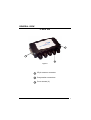
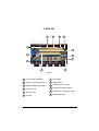
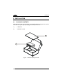
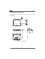
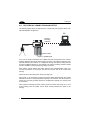
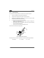
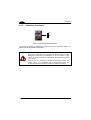
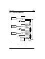
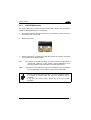
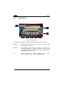
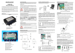
C-BOX 200 Installation Manual C-BOX 200 Installation Manual C-BOX 200 INSTALLATION MANUAL DATALOGIC S.p.A. Via Candini 2 40012 - Lippo di Calderara di Reno Bologna - Italy C-BOX 200 Ed.: 01/2002 ALL RIGHTS RESERVED Datalogic S.p.A. reserves the right to make modifications and improvements without prior notification. Datalogic shall not be liable for technical or editorial errors or omissions contained herein, nor for incidental or consequential damages resulting from the use of this material. Product names mentioned herein are for identification purposes only and may be trademarks and or registered trademarks of their respective companies. Datalogic S.p.A. 2001 821000561 (Rev. A) CONTENTS GUIDE TO INSTALLATION .........................................................................iv GENERAL VIEW .......................................................................................... v SAFETY PRECAUTIONS............................................................................vii Power Supply...............................................................................................vii 1 1.1 GENERAL FEATURES ................................................................................ 1 Description .................................................................................................... 1 2 2.1 2.2 2.3 2.4 2.4.1 2.4.2 2.4.3 2.4.4 2.4.5 2.4.6 2.4.7 2.5 2.6 2.7 2.7.1 2.7.2 INSTALLATION............................................................................................ 2 Package Contents......................................................................................... 2 Opening the Device ...................................................................................... 3 Mechanical Installation.................................................................................. 4 Electrical Connections and Setup ................................................................. 6 Power Supply................................................................................................ 7 System Wiring............................................................................................... 8 Chassis Grounding Jumper Settings........................................................... 10 Multidrop Address Selection ....................................................................... 11 RS485 Bus Termination .............................................................................. 12 Connection to a Multiplexer......................................................................... 13 OM4000 Jumper Settings ........................................................................... 14 9-Pin Scanner Auxiliary Serial Interface...................................................... 15 Scanner Requirements ............................................................................... 16 Operating Modes ........................................................................................ 16 GET/SEND Buttons .................................................................................... 17 LED Indicators ............................................................................................ 18 3 TECHNICAL FEATURES ........................................................................... 19 iii GUIDE TO INSTALLATION The following can be used as a checklist to verify all of the steps necessary for complete installation of the C-BOX 200. 1) Read all information in the section "Safety Precautions" at the beginning of this manual. 2) Correctly position and mount the C-BOX 200 within the reach of the barcode scanner cable, according to the information in paragraph 2.3. 3) Provide correct system cabling according to the signals necessary for your application and RS485 settings (see all sub-paragraphs under 2.4) The installation is now complete. iv GENERAL VIEW C-BOX 200 3 1 2 Figure A 1 25-pin scanner connector 2 Compression connectors 3 Cover screws (4) v C-BOX 200 7 8 9 12 4 5 10 3 11 1 2 6 Figure B 1 Power switch (ON/OFF) vi 2 Spring clamp terminal blocks 7 GET button 8 SEND button 3 Multidrop address switches 9 Auxiliary port connector 4 Power on LED 10 Chassis grounding selector 5 Warning LED 11 Termination resistance switch 6 Tx LED 12 OM4000 jumpers SAFETY PRECAUTIONS POWER SUPPLY ATTENTION: READ THIS INFORMATION BEFORE INSTALLING THE PRODUCT - This product is intended to be installed by Qualified Personnel only. The C-BOX 200 is intended to be supplied by an NEC Class 2 power source, rated 10-30 V, minimum 0.65 A. See par. 2.4.1 for correct power supply connections. vii viii GENERAL FEATURES 1 1 GENERAL FEATURES 1.1 DESCRIPTION The C-BOX 200 is a connection box which can be used as an accessory of the Datalogic scanners to perform the following functions: • Facilitate the connection of the scanner signals using a spring clamp connector. • Perform a conversion from RS232 to RS485 multidrop system to connect a RS232 scanner to a multidrop network. • Optocoupled RS485 interface is used over long distances or in electrically noisy environments. • Get the scanner configuration and store it in memory. • Send the configuration stored in memory to the scanner. The C-BOX 200 mechanical dimensions are 167 x 115 x 40 mm (6.57 x 4.53 x 1.57 in.). It weighs about 340 g. (12 oz). Electrical connection is provided through spring clamp terminal blocks inside the CBOX 200. The scanner is connected to the C-BOX 200 through a 25-pin connector placed on the left side of the housing. A 9-pin connector placed inside the C-BOX 200 facilitates connection between an external PC and the auxiliary serial interface of the scanner. 1 C-BOX 200 2 2 INSTALLATION 2.1 PACKAGE CONTENTS Verify that the C-BOX 200 and all the parts supplied with the equipment are present and intact when opening the packaging; the list of parts includes: 1) C-BOX 200 2) Installation manual 2 1 Figure 1 - C-BOX 200 package contents 2 INSTALLATION 2.2 2 OPENING THE DEVICE To install the C-BOX 200 or during normal maintenance, it is necessary to open it by unscrewing the four cover screws: The C-BOX 200 must be disconnected from the power supply during this operation. CAUTION Figure 2 - Opening the C-BOX 200 It is possible to perform the following operations: • Proceed with the cable connections (see paragraph 2.4.2). • Set the multiplexer address selection on the rotary switches. • Mount the C-BOX 200 to a wall or panel. 3 C-BOX 200 2 2.3 MECHANICAL INSTALLATION The diagram below gives the overall dimensions of the C-BOX 200 and may be used for its installation. C-BOX Figure 3 - Overall dimensions 4 mm in INSTALLATION 2 C-BOX 200 can be installed to operate in different positions. The two screw holes inside the housing of the C-BOX 200 are for mechanical fixture (Figure 4). To mount the C-BOX 200: 1) Open the C-BOX 200 by unscrewing the 4 cover screws. If necessary, using the two mounting holes inside the device as a pattern, mark the panel with an appropriate object and then drill two holes in the panel. 2) Align the C-BOX 200 and insert two screws and screw them into the panel until tight (see Figure 4). Figure 4 - Mounting C-BOX 200 5 C-BOX 200 2 2.4 ELECTRICAL CONNECTIONS AND SETUP The following figure shows the typical layout. The dotted line in the figure refers to an optional hardware configuration. PC Scanner Auxiliary Interface SCANNER TX D ATA EXT TR IG GOOD R EAD POWE R ON System Cables Figure 5 – System layout A PC can be quickly connected to the C-BOX 200 (and consequently to the scanner auxiliary interface) through the internal 9-pin connector. This allows monitoring of the data transmitted by the scanner or configuration through the WinHost utility (see the scanner Installation Manual for more details). The scanner auxiliary interface signals are also available on the internal spring clamp connectors. After making system cabling and switch settings (see sub-paragraphs under 2.4), connect the scanner to the 25-pin connector on the left side of the C-BOX 200 housing. Switch ON the C-BOX 200 power switch (see Figure 6). After power on, an automatic connection procedure takes place between the C-BOX 200 and the scanner. During this phase, requiring a few seconds, the warning LED is turned ON. Once the procedure had been completed successfully, the warning LED is turned OFF. After system functioning has been verified, close the C-BOX 200 using the 4 cover screws making sure the rubber seal is fitted correctly between the parts of the housing. 6 INSTALLATION 2.4.1 2 Power Supply Power is supplied to the C-BOX 200 through the pins provided on the spring clamp connector. The power switch (see Figure 6) switches the power supply ON or OFF for both the C-BOX 200 and the connected scanner. ON S1 OFF Figure 6 - Power switch ON/OFF positions USER INTERFACE C-BOX 1 VS V+ (10 - 30 Vdc) 2 GND GND Figure 7 - Power supply connections Pin 1 is also electrically connected to pins 3 and 5, just as pin 2 is electrically connected to pins 4 and 6. This is useful for external trigger/inputs connections. NOTE The power supply must be between 10 and 30 Vdc only. 7 C-BOX 200 2 2.4.2 System Wiring The connection and wiring procedure for C-BOX 200 is described as follows: 1) Open the C-BOX 200 as described in paragraph 2.2. 2) Verify that the C-BOX 200 power switch is off (see Figure 6). 3) Unscrew the compression connectors and pass all the system cables through them into the C-BOX 200 housing. 4) To connect the power and input/output signals: • Prepare the individual wires of the system cables by stripping the insulation back approximately 1 cm. • Using a device such as a screwdriver, push down on the lever directly next to the clamp (see Figure 8). • Insert the wire into the clamp and release the lever. The wire will now be held in the spring clamp. Figure 8 - System cable connections The wiring used can be solid or stranded but must meet the following specifications. All positions: 8 24 - 16 AWG 0.2 - 1.5 mm² INSTALLATION 2 The C-BOX 200 spring clamp connector pinouts are indicated in the following table. Refer to the scanner Installation Manual for details. Pin 1, 3, 5 2, 4, 6 7, 8 *9, 13 *10, 14 *11, 15 *12, 16 20, 33, 34, 40 21 23 27 28 35 37 39 22 24 25, 26 29 30 31 32 36 38 Name VS GND EARTH GROUND RS485 CABLE SHIELD RS485 REF RTX485+ RTX485Reserved OUT1+ OUT2+ EXT TRIG+ EXT TRIGTXA RXA SGND DS2100 DS2400 OUT REF OUT REF NC NC NC NC NC RTSA CTSA DS4300 DS4600 OUT1OUT2Reserved IN1+ IN1IN2+ IN2GND SGND AUX *The signals on pins 9, 10, 11 and 12 are repeated on pins 13, 14, 15 and 16 to facilitate network connections (i.e. Multiplexer connections using the RS485 half-duplex Interface). In this way the network bus can enter and exit the C-BOX from different spring clamps but be physically connected together. Pin 7 or 8 should be connected to the earth ground. Pin 17, 18 and 19 are not present in the C-BOX 200 model. NOTE 9 C-BOX 200 2 2.4.3 Chassis Grounding Jumper Settings The scanner chassis grounding method can be selected by positioning a jumper (see Figure 9). In this way the scanner chassis can be connected to earth ground (only if pins 7 or 8 are connected to a good earth ground) or to the power supply ground signal. The scanner chassis can also be left floating but, in this case, the jumper must be removed. to EARTH GROUND (default) to GND floating Figure 9 – Chassis grounding The C-BOX 200 is now installed which completes the electrical connections for your scanning system. 10 INSTALLATION 2.4.4 2 Multidrop Address Selection For RS485 half-duplex interface connections, the scanner multidrop address should be set using the rotary switches placed inside the C-BOX 200. The valid address range is from 00 to 31. This value is read only at power-on; any change at run-time has no effect. If an invalid value is detected (32-99) the C-BOX cannot communicate with the Multiplexer and the green LED remains off. Furthermore, the SEND command configures the scanner using the previously configured valid scanner address. TENS UNITS Figure 10 - Rotary switches 11 C-BOX 200 2 2.4.5 RS485 Bus Termination ON OFF S2 Figure 11 - Termination resistance switch The switch S2 enables or disables the insertion of the bus termination resistor for RS485 Half Duplex Multidrop applications. CAUTION 12 In Multiplexer applications the termination resistor must be enabled ONLY on the last device of the chain, the farthest away from the Multiplexer (assuming the Multiplexer is the first device of the chain). On all the other devices this resistor MUST NOT be enabled (S2 = OFF). Normally it is not necessary to enable the terminator resistor (S2 always OFF); it is suggested only in applications where the communication speed or the bus length are critical parameters. INSTALLATION 2.4.6 2 Connection to a Multiplexer The following figure shows a multidrop layout with C-BOX 200 devices connected to a Multiplexer: (*) SCANNER C-BOX 200 12 RTX485#N 11 RTX485+ (up to 31) 10 RS485 REF 9 CABLE SHIELD EARTH GROUND C-BOX 200 SCANNER #1 13 14 15 16 CABLE SHIELD RS485 REF RTX485+ RTX485- 12 11 10 9 RTX485RTX485+ RS485 REF CABLE SHIELD 13 14 15 16 CABLE SHIELD RS485 REF RTX485+ RTX485- 12 11 10 9 RTX485RTX485+ RS485 REF CABLE SHIELD max 1200 m EARTH GROUND SCANNER C-BOX 200 #0 EARTH GROUND Three wires + shield MULTIPLEXER CABLE SHIELD RS485 REF RTX485+ RTX485- EARTH GROUND 120 Ohm (*) If necessary enable the termination resistor only in the last device. Figure 12 - Multiplexer connection 13 C-BOX 200 2 2.4.7 OM4000 Jumper Settings J1 J2 Figure 13 - OM4000 jumpers The jumpers allow connection to the EXT TRIG signals on separate spring clamp terminals for applications which use the OM4000 Oscillating Mirror in Trigger Mode. They are used together and they have the following significance: when a jumper is in the J1 position (see Figure above) pin 40 is connected to pin 27 (EXT TRIG+); a jumper in J2 position connects pin 20 to pin 28 (EXT TRIG-). If the jumpers are removed pin 20 and pin 40 are disconnected. 14 INSTALLATION 2.5 2 9-PIN SCANNER AUXILIARY SERIAL INTERFACE The scanner auxiliary serial interface available on the internal 9-pin connector can be used either for configuration through WinHost or for data monitoring. The details of the connector pins are indicated in the following table: Figure 14 - 9-pin male connector Pin 1 2 3 4 5 6 9 Name 9-pin connector pinout Function RXA TXA SGND N.C. Auxiliary RS232 Auxiliary RS232 N.C. Signal Ground N.C. N.C. DS2100 - DS2400 7 CTSA Auxiliary Handshake RS232 8 RTSA Auxiliary Handshake RS232 DS4300 - DS4600 7 SGND AUX Auxiliary Signal Ground 8 GND Ground 15 C-BOX 200 2 2.6 1) SCANNER REQUIREMENTS The C-BOX 200 can be connected to the following scanners through the 25-pin connector illustrated in Figure A. DS2100 DS4300 DS2400 DS4600 It is necessary to use RS232 model (X0XX) for DS2100 and DS2400 scanner, while DS4300 and DS4600 RS232 interface must be selected by the user. 2) At least one Terminator Character should be enabled in the connected scanner (see the Terminator parameters in the Data Format section of the Help On Line). 3) It is necessary to set the scanner main interface communication speed (Baud Rate), so that it is the same as the Multidrop bus speed. In fact, during the connection procedure, the C-BOX 200 gets its main interface speed from the scanner to initialize its RS485 Multidrop optocoupled serial interface. If both the baud rate and the device address are correct the communication takes place which causes the green LED to blink slightly. The device address must be pre-set through the two rotary switches S4 and S5 (see Figure 10). 2.7 OPERATING MODES Once the connection procedure is completed (the warning LED is OFF), the C-BOX 200 is ready to receive code strings from the scanner's RS232 main interface. Then, it converts them to the RS485 multidrop network by using MUX32 protocol. Through the C-BOX 200 internal buttons, it is possible to communicate with the scanner to perform one of the following functions: • Get scanner configuration • Send a configuration to the scanner At the end of each function the scanner returns to the previous operating mode. 16 INSTALLATION 2.7.1 2 GET/SEND Buttons The C-BOX 200 has two internal function buttons (GET, SEND). The procedure to enable the GET/SEND function is the following: 1. Press both the buttons GET and SEND at the same time for at least one second; the warning LED is turned ON. 2. Release the buttons. GET 3. SEND Press the left button corresponding to the GET function or press the right button corresponding to the SEND function. GET – (left button): the C-BOX 200 reads the current scanner configuration and permanently copies it in its own memory support (EEPROM). The CBOX 200 preserves this configuration also when switched off. SEND - (right button): the C-BOX 200 sends the configuration previously stored in its own permanent memory support to the scanner’s EEPROM. NOTE Once the buttons are released in step 1, a ten-second timeout starts. If no button is pressed within this time, the procedure will be cancelled. In any case, the warning LED is turned OFF at the end of each procedure. 17 C-BOX 200 2 2.7.2 LED Indicators Power on Warning Tx Figure 15 - LED Indicators The three internal LEDs of the C-BOX 200 (see Figure 15) indicate the following: POWER ON (red) indicates the C-BOX 200 is connected to the power supply and the power switch is ON. WARNING (red) indicates a warning or error condition: it is ON when a connection procedure is in progress (the system is busy) or during a GET/SEND procedure. It blinks when an error condition occurs. Normally this LED should be OFF. TX (green) indicates the RS485 Multidrop activity. communication takes place, this LED will blink slightly. 18 When TECHNICAL FEATURES 3 3 TECHNICAL FEATURES ELECTRICAL FEATURES Power Supply voltage Power consumption max. 10 to 30 Vdc 1.4 W + scanner USER INTERFACE LED indicators Power ON, Warning, Tx (RS485 Multidrop activity) PHYSICAL FEATURES Mechanical dimensions Weight 167 x 115 x 40 mm (6.57 x 4.53 x 1.57 in.) about 340 g. (12 oz.) SOFTWARE FEATURES Parameter storage Non-volatile internal memory ENVIRONMENTAL FEATURES Operating temperature -10 to 50 °C (14 to 122 °F) Storage temperature -20 to 70 °C (-4 to 158 °F) Humidity max. Vibration resistance 90% non condensing IEC 68-2-6 test FC 1.5 mm; 10 to 55 Hz; 2 hours on each axis Shock resistance IEC 68-2-27 test EA 30G; 11 ms; 3 shocks on each axis Protection class IP64 (when correctly connected to the scanner) The features given are typical at a 25 °C ambient temperature (if not otherwise indicated). NOTE 19 DATALOGIC S.p.A., Via Candini, 2 40012 - Lippo di Calderara Bologna - Italy dichiara che declares that the déclare que le bescheinigt, daß das Gerät declare que el C-BOX 200, active connection box 01 e tutti i suoi modelli and all its models et tous ses modèles und seine modelle y todos sus modelos sono conformi alle Direttive del Consiglio Europeo sottoelencate: are in conformity with the requirements of the European Council Directives listed below: sont conformes aux spécifications des Directives de l'Union Européenne ci-dessous: der nachstehend angeführten Direktiven des Europäischen Rats: cumple con los requisitos de las Directivas del Consejo Europeo, según la lista siguiente: 89/336/EEC EMC Directive e and et und y 92/31/EEC, 93/68/EEC emendamenti successivi further amendments ses successifs amendements späteren Abänderungen succesivas enmiendas Basate sulle legislazioni degli Stati membri in relazione alla compatibilità elettromagnetica ed alla sicurezza dei prodotti. On the approximation of the laws of Member States relating to electromagnetic compatibility and product safety. Basée sur la législation des Etates membres relative à la compatibilité électromagnétique et à la sécurité des produits. Über die Annäherung der Gesetze der Mitgliedsstaaten in bezug auf elektromagnetische Verträglichkeit und Produktsicherheit entsprechen. Basado en la aproximación de las leyes de los Países Miembros respecto a la compatibilidad electromagnética y las Medidas de seguridad relativas al producto. Questa dichiarazione è basata sulla conformità dei prodotti alle norme seguenti: This declaration is based upon compliance of the products to the following standards: Cette déclaration repose sur la conformité des produits aux normes suivantes: Diese Erklärung basiert darauf, daß das Produkt den folgenden Normen entspricht: Esta declaración se basa en el cumplimiento de los productos con las siguientes normas: EN 55022, August 1994: LIMITS AND METHODS OF MEASUREMENTS OF RADIO DISTURBANCE CHARACTERISTICS OF INFORMATION TECHNOLOGY EQUIPMENT (ITE) EN 50082-2, March 1995: ELECTROMAGNETIC COMPATIBILITY. GENERIC IMMUNITY STANDARD. PART 2: INDUSTRIAL ENVIRONMENT Ruggero Cacioppo Lippo di Calderara, 07/03/2001 Quality Assurance Supervisor