1
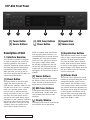
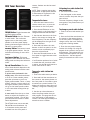
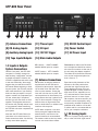
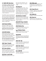
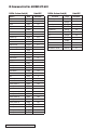
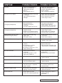
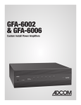
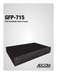
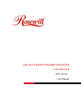
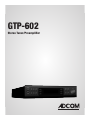
GTP-602
Stereo Tuner/Preamplifier
ABOUT ADCOM
PERFORMANCE AND VALUE
In the world of high performance electronics, Adcom has done the impossible: make state-of-theart components that are easy to use at an affordable price. In doing this, Adcom has created a revolution in the world of consumer electronics. By creating some of the most renowned components
and offering them at affordable prices, Adcom has enabled more people to enjoy their favorite
music and movies at top performance levels. Perhaps Audio Magazine said it best: “No competing
company I know can provide a similar balance of sound quality, power and affordability.”
AWARD WINNING
Innovation is our stronghold, and our numerous awards year after year prove that we’re never
satisfied to rest on our reputation. From our legendary high current amplifiers to our state-of-theart digital processors, Adcom components consistently impress even the most demanding audiences. Adcom components have won over 25 Product of the Year and Special Recognition citations
from Audio Video International, 3 Diapason D’Or Awards, 7 Consumer Electronics Show Design and
Engineering Awards, and have appeared on Stereophile’s “Recommended Components” lists over
70 times since 1988. A reputation worth its weight in gold.
ENGINEERING PASSION
Every Adcom component is not only designed to reproduce the highest quality sound and picture,
but to also deliver the greatest possible value. It is our engineers’ passion for perfection that has
enabled our components to be judged the equivalent of others costing two, three, or even five
times as much. Our engineering team consistently strives to develop and design products that
will exceed your expectations. Our goal at Adcom is to let more consumers hear high-end quality
sound and see high-end video without paying high-end prices.
All Adcom components are the result of a long-standing dedication to innovation, quality, simplicity and value. Adcom, we have the power, and now so do you.
ADCOM
A division of Klein Technology Group, LLC
8541 East Anderson Drive
Scottsdale, Arizona 85255 USA
Telephone: (480) 607-2277
Fax: (480) 348-9876
Email: [email protected]
Web: www.adcom.com
ADCOM is a registered trademark of Klein Technology Group, LLC.
Copyright © 2003 Klein Technology Group, LLC. All rights reserved. No part of this manual may be reproduced
or electronically transmitted without the express written consent of Klein Technology Group, LLC.
2 | ADCOM GTP-602 Owner’s Manual
TABLE OF CONTENTS
WELCOME .................................................................... 2
SAFETY INFORMATION ...................................................... 4
INTRODUCTION & UNPACKING .............................................. 5
DESCRIPTION OF UNIT
FRONT PANEL DRAWING .................................................... 6
1.1 INTERFACE OVERVIEW ............................................ 6-7
REAR PANEL DRAWING ...................................................... 8
1.2 INPUTS & OUTPUTS SYSTEM CONNECTIONS .................... 8-9
REMOTE CONTROL DRAWING .............................................. 10
2.1 OVERVIEW OF THE GRC-800 ....................................... 11
2.5 DISCRETE CUSTOM CODES FOR INSTALLERS .................... 12
TROUBLESHOOTING
RESOLVING PROBLEMS .................................................... 13
TROUBLESHOOTING ....................................................... 14
SERVICE INFORMATION .................................................... 14
WARRANTY ................................................................. 15
GTP-602 SPECIFICATIONS ................................................. 16
ADCOM GTP-602 Owner’s Manual | 3
THE FOLLOWING PRECAUTIONS AND SAFETY INSTRUCTIONS
ARE REQUIREMENTS OF UL AND CSA SAFETY REGULATIONS
Warning: To reduce the risk of fire or electric shock, do
not expose this unit to rain or moisture.
CAUTION
RISK OF ELECTRIC SHOCK
DO NOT OPEN
The graphic symbol of a lightning flash with an
arrow point within a triangle signifies that there
is dangerous voltage within the unit and it poses
a hazard
to anyoneSHOCK
removing the cover to gain
RISK
OF ELECTRIC
access to the interior of the unit. OnIy qualified
DO NOT OPEN
service personnel should make any such attempt.
CAUTION
The graphic symbol of an exclamation point within
an equilateral triangle warns a user of the device
that it is necessary to refer to the instruction manual
and its warnings for proper operation of the unit.
Do not place this unit on an unstable cart, stand, tripod,
bracket, or table. The unit may fall, causing serious
injury to a child or adult, and serious damage to the
unit. Use only with a cart, stand, tripod, bracket, or
table recommended by the manufacturer or sold with
the unit. Any mounting of the device should follow the
manufacturer’s instructions, and should use a mounting
accessory recommended by the manufacturer.
Read all the safety and operating instructions before connecting or using
this unit.
Retain this notice and the owner’s manual for future reference.
All warnings on the unit and in its operating instructions should be adhered to.
All operating and use instructions should be followed.
Do not use this unit near water. For example, near a bathtub, washbowl,
kitchen sink, laundry tub, in a wet basement, or near a swimming pool.
ATTENTION
POUR PREVENIR LES CHOCS ELECTRIQUES NE PAS UTILISER CETTE FICHE
POLARISEE AVEC UN PROLONGATEUR, UNE PRISE CE COURANT OU UNE
AUTRE SORTIE CE COURANT, SAUF SI LES LAMES PEUVENT ETRE INSEREES
A FOND SANS EN LAISSER AUCUNE PARTIE A DECOUVERT.
CAUTION
TO PREVENT ELECTRIC SHOCK DO NOT USE THIS POLARIZED PLUG WITH
AN EXTENSION CORD, RECEPTACLE OR OTHER OUTLET UNLESS THE
BLADES CAN BE FULLY INSERTED TO PREVENT BLADE EXPOSURE.
CAUTION POWER LINES
Any outdoor antenna must be located away from all power lines.
OUTDOOR ANTENNA GROUNDING
If an outside antenna is connected to your tuner or tuner/preamplifier,
be sure the antenna system is grounded so as to provide some protection
against voltage surges and built-up static charges. Section 810 of the
National Electrical Code, ANSI/NFPA No. 701984, provides information
with respect to proper grounding of the mast and supporting structure,
grounding of the lead-in wire to an antenna discharge unit, size of
grounding conductors, location of antenna discharge unit, connection to
grounding electrodes, and requirements for the grounding electrode.
a. Use No.10 AWG (5.3 mm2) copper, No.8 AWG (8.4 mm2) aluminum, No.17
AWG (1.0 mm2) copper clad steel or bronze wire, or larger, as a ground
wire.
b. Secure antenna lead-in and ground wires to house with stand-off
insulators spaced from 46 feet (1.221.83 m) apart.
c. Mount antenna discharge unit as close as possible to where lead-in enters
house.
d. Use jumper wire not smaller than No.6 AWG (13.3 mm2) copper, or the
equivalent, when a separate antenna grounding electrode is used. See NEC
Section 810-21 (j).
EXAMPLE OF ANTENNA GROUNDING AS PER NATIONAL ELECTRICAL CODE
INSTRUCTIONS CONTAINED IN ARTICLE 810. RADIO AND TELEVISION EQUIPMENT.
power lines
The unit should be installed so that its location or position does not interfere
with its proper ventilation. For example, it should not be situated on a
bed, sofa, rug, or similar surface that may block the ventilation openings;
or placed in a built-in installation, such as bookcase or cabinet, that may
impede the flow of air through its ventilation openings.
ground clamp
service entrance
conductors
standoff
insulators, b
The unit should be situated away from heat sources such as radiators, heat
registers, stoves, or other devices (including amplifiers) that produce heat.
mast
The unit should be connected to a power supply outlet only of the voltage
and frequency marked on its rear panel.
The power supply cord should be routed so that it is not likely to be walked
on or pinched, especially near the plug, convenience receptacles, or where
the cord exits from the unit.
service
entrance
equipment
antenna
lead-in wire
ground wire, a,b
ground clamps
antenna
discharge
unit, c
Clean unit only as recommended in its instruction manual.
The power supply cord of the unit should be unplugged from the wall outlet
when it is to be unused for a long period of time.
Care should be taken so that objects do not fall, and liquids are not spilled,
into the enclosure through any openings.
This unit should be serviced by qualified service personnel when:
A. The power cord or the plug has been damaged; or
B. Objects have fallen, or liquid has been spilled, into the unit; or
C. The unit has been exposed to rain, or liquids of any kind; or
D. The unit does not appear to operate normally, or exhibits a marked
change in performance; or
E. The device has been dropped, or the enclosure damaged.
DO NOT ATTEMPT SERVICING OF THIS UNIT YOURSELF.
4 | ADCOM GTP-602 Owner’s Manual
REFER SERVICING TO QUALIFIED SERVICE PERSONNEL.
to external antenna
terminals of radio receiver
power service grounding
electrode system
(e.g. interior metal water pipe)
bonding jumper, d
ground wire, a,b
ground clamps
optional antenna grounding
electrode driven 8 feet (2.44 M) into
the earth if required by local codes.
NOTE TO CATV SYSTEM INSTALLER
This reminder is provided to call the CATV system installer’s attention to
Article 82022 of the National Electrical Code that provides guidelines for
proper grounding and, in particular, specifies that the cable ground shall
be connected to the grounding system of the building, as close to the
point of cable entry as practical.
Congratulations on your decision
to purchase the GTP-602 tuner/
preamplifier. Your new ADCOM component was designed to deliver incredible sound and years of reliable performance. Audition the GTP-602 paired
with an ADCOM power amp and DVD
player and you will experience what
high performance is all about. To realize the full potential of your GTP-602,
and before making any connections
to it, please read these operating and
installation instructions thoroughly.
Key Features
• RDS tuner
• Phono input stage
• RS 232 control
• Torriodial power transformer
Unpacking the GTP-602
Before your new ADCOM tuner-preamplifier left our factory, it was carefully
inspected for physical imperfections
and tested for all electrical parameters
as a routine part of ADCOM’s systematic quality control. This, along with
full operational and mechanical testing, should ensure a product flawless
in both appearance and performance.
After you have unpacked the GTP602, inspect it for physical damage.
Save the shipping carton and all packing material as they are intended to
reduce the possibility of transportation damage should the preamplifier
ever need to be shipped again. In the
unlikely event damage has occurred,
notify your dealer immediately and
request the name of the carrier so a
written claim to cover shipping damages can be initiated. The right to a
claim against a public carrier can be
forfeited if the carrier is not notified
promptly in writing and if the shipping
carton and packing materials are not
available for inspection by the carrier.
Save all packing materials until the
claim has been settled.
Placing the GTP-602
Although the GTP-602 does not generate much heat, it is good practice
to provide adequate ventilation for
the unit. Therefore, the GTP-602
should be kept away from external
sources of heat such as radiators and
hot-air ducts.
We recommend that you exercise care
when placing components on top of the
GTP-602. If you are placing a heat producing component (such as an amplifier) on top of or below the GTP-602, it
is recommended that you allow at least
three (3) inches vertical spacing for
proper airflow.
We also recommend that you leave five
(5) inches of space behind the unit for
additional airflow and to allow space
for interconnects to hang freely.
5"
e
ranc
clea
If you observe these recommendations, the GTP-602 will perform reliably
in any reasonable environment. You
should also pay attention to such normal considerations as protection from
excessive dust and moisture.
The optimal performance of your new
GTP-602 will ultimately depend on the
care with which you make the connections between the amplifier, preamplifier and loudspeakers. All input and
output signal connections should be
made only with high quality, low-loss,
low capacitance cables. For recommendations of the type and quality of
interconnections that are best for your
applications, consult with your ADCOM
retailer.
Safety Information
There are no user serviceable parts
inside. Refer all servicing to qualified
service personnel.
The unit must be connected to a power
supply only of the type and voltage
specified on the rear panel. Connect
the component to the power outlet only
with the supplied power supply cable or
an exact equivalent. Do not modify the
supplied cable. Do not defeat grounding
and/or polarization provisions. The
cable should be connected to a 3-pin
polarized wall outlet, matching the
wide blade of the plug to the wide slot
of the receptacle. Do not use extension
cords. Do not route the power cord
where it will be crushed, pinched,
bent, exposed to heat, or damaged in
any way. Pay particular attention to
the power cord at the plug and where
it exits the back of the unit. The power
cord should be unplugged from the wall
outlet if the unit is to be left unused
for a long period of time. Immediately
stop using the component and have
it inspected and/or serviced by a
qualified service agency if:
• the power supply cord or plug has
been damaged;
• objects have fallen or liquid has
been spilled into the unit;
• the unit has been exposed to rain;
• the unit shows signs of improper
operation; or
• the unit has been dropped or
damaged in any way.
ADCOM GTP-602 Owner’s Manual | 5
GTP-602 Front Panel
1
2
3
[1] Power Button
[2] Source Buttons
Description of Unit
1.1 Interface Overview
The GTP-602’s front panel is designed
for ease of operation. All controls are
logically grouped for easy, intuitive
operation. Familiarize yourself with the
preceding diagram and read the short
explanations of each feature below.
When you finish, you will be well on
your way to enjoying the GTP-602’s convenience and sound quality.
[1] Power Button
The power button on the front panel
toggles the unit between the “on”
mode and the “stand-by” mode. For the
GTP-602 to be in the “on” or “standby”
mode, the rear panel power switch
must be in the on postion (see next
section for details). In the “on” mode
the LED in the power button will be
red and the front panel display will be
illuminated, in the “stand-by” mode the
LED will be amber and the front panel
display will be off. If the unit is in the
“standby” mode, the remote control
can be used to switch the unit on.
6 | ADCOM GTP-602 Owner’s Manual
4
[3] RDS Tuner Buttons
[4] Power Button
3
6
[5] Equalization
[6] Volume knob
NOTE: In stand-by mode the GTP-602
uses very little power. However, it is
recommended that you switch the unit
completely off, using the rear panel
switch if it is not going to be used for
more than a couple of days. When
the GTP-602 is plugged into the wall,
current may still be flowing into the
transformer. Only when the GTP-602 is
unplugged is all current into the device
stopped.
[2] Source Buttons
The source buttons are used to select
the device to which you would like to
listen. The LED in the button of the
active source will be illuminated.
[3] RDS Tuner Buttons
These buttons are utilized to control
the AM/FM tuner. The RDS tuner overview provides more detail on their
operation.
[4] Display Window
5
The display area shows all vital information when the unit is operational.
[5] Equalization Buttons
These buttons provide control of adjustments to bass, treble and the balance
functions. To adjust these functions,
first push the treble, bass or balance
button, then use the up/down buttons
to the left of the display to make the
desired change. In the bypass mode the
bass and treble circuits are removed
from the circuit path.
[6] Volume Knob
The Volume control adjusts the overall
loudness of the signals being fed to the
preamplifier outputs. Unlike conventional controls, the GTP-602’s volume
control doesn’t have a start or end position. Volume can also be adjusted from
the remote control using the volume up
or down buttons. The Volume control
does not affect recordings made using
the Tape outputs. Volume setting can
range from -80dB to +10dB.
RDS Tuner Overview
remote. Stations can also be tuned
manually.
NOTE: Tuner reception cannot take
place unless an appropriate AM and/
or FM antenna is connected to the
rear panel of the GTP-602.
To operate the tuner:
1. Press the tuner button on the
remote control once, or press the
tuner button on the front panel.
FM/AM Button: Toggles between AM
and FM frequency bands.
FM mode Button: Sets the FM tuner
to mono mode. The word mono
appears next to the tuner preset
number in the front panel display.
Pressing the button again returns the
FM tuner to stereo mode.
memory Button: This button is used
to program preset stations. See the
instructions following for more information.
tune/preset button: This button
toggles the tuner between the direct
tuning mode and the preset selectionmode.
Up and Down Buttons: The function of these buttons depends on the
tuning mode selected with the tune/
preset button.
In preset mode (indicated in the
display area): Press the down button
to scroll to a lower number preset;
press the up button to scroll to a
higher preset number. This is a “wraparound” function, so that going from
the highest number preset, the tuner
will go to the lowest preset number
or vice-versa when tuning either up
or down.
In tune mode: Press the up or down
button to adjust the frequency currently being received. You can also
press and hold the buttons to make
faster adjustments.
Listeneing to a radio station that
you have preset:
1. Set the GTP-602 to tuner.
2. Use the keypad on the remote
control to select the preset that you
want to hear.
The tuner frequency changes to the
new station in the preset memory of
the GTP-602.
2. Press the AM/FM button on the
remote control or the front panel to
change between AM and FM bands.
To change a preset radio station:
3. Use the tune buttons on the front
panel or the remote to change the
tuner frequency. The new frequency
will be displayed to the right of the
FM or AM indicator.
2. Press and hold the mem button on
the remote or the memory button
on the front panel. The display will
change to show the word “memory”
along with a flashing number.
4. Press and hold either the tune
buttons on the front panel or on the
remote to scan continuously up or
down the selected band.
3. Enter the new preset/memory
location (01 through 12) using the
keypad on the remote or the up and
down buttons. This replaces the previously memorized preset with your
new selection. You have approximately five seconds to enter a number.
5. Press the FM mode button on the
front panel to toggle between stereo
and mono.
If an FM station produces lots of noise
or sound that cuts in and out while
in stereo, use the FM mode button to
switch from stereo to mono.
1. Tune to the new radio station you
desire.
To preset a radio station into
memory:
1. Tune to the radio station you desire.
2. Press and hold the mem button on
the remote or the memory button on
the front panel for 3 seconds to store
a station into a preset location. The
display will change to show the word
“memory” along with a flashing number.
3. Use the up or down buttons to
select the preset number that you
wish program. This programs the current radio station to that memory
location. You have approximately five
seconds to enter a number.
The GTP-602 tuner can receive AM,
FM and FM stereo broadcasts. Up
to 24 stations can be preset and
accessed from the front panel or
ADCOM GTP-602 Owner’s Manual | 7
GTP-602 Rear Panel
7
8
9
10 11
12 13
14
15
16
17
[7] Antenna Connections
[11] Phono Input
[15] RS232 Control Input
[8] CD Analog Inputs
[12] IR Input
[16] Power Switch
[9] Auxiliary Analog Inputs [13] 12V DC Trigger
[10] Tape Inputs/Outputs
[14] Main Audio Outputs
1.2 Inputs & Outputs
System Connections
RED centers = RIGHT CHANNEL
ANALOG AUDIO inputs or outputs
Like the front panel, the GTP-602’s
rear panel is carefully arranged to
make hookup, configuration, and use
as simple as possible. However, the
GTP-602’s capabilities take some study
to use most effectively. We strongly
suggest that you read this section of
the manual before beginning to hook
up your system. You will save yourself
much time and effort if you carefully
think out what you expect from your
system: consider the components you
will use, where they’ll be placed,
and how you will want them to work
together. The diagrams and notes in
this section will probably answer most
of your questions about interfacing
the GTP-602 with other components in
your system.
Note that the GTP-602’s RCA-style
jacks have color-coded centers to
make connections easier. Use this key
to help route cables properly:
8 | ADCOM GTP-602 Owner’s Manual
WHITE centers = LEFT CHANNEL
ANALOG AUDIO inputs or outputs
[7] Antenna Connections
AM Antenna: An AM loop antenna is
supplied with the GTP-602 and is
required for AM reception. Open the
clip terminal lever and insert the
wire from the antenna. Closing the
lever will lock the wire in place. Test
various positions for the antenna, but
always ensure the loop is placed vertically for best reception. Placing the
antenna close to large metal items
such as metal shelves or radiators may
interfere with reception.
NOTE: When reception is not satisfactory using the supplied AM loop
antenna alone, connection of an
external antenna is recommended.
The antenna cable to the loop antenna must not exceed three meters.
[17] AC Power Input
FM Antenna: A ribbon wire FM antenna is included and should be connected to the FM connector at the rear of
the unit using the adapter supplied.
The ribbon aerial should be mounted
on a vertical surface and placed so
that it forms a ‘T’.
Experiment with placement of the
antenna to find the position that
gives the best signal strength and
lowest background noise. An inadequate FM signal normally results in
high levels of hiss, especially in stereo, and interference from external
electrical sources. In areas of poor
FM reception, the tuner section’s performance can be improved by using
an externally mounted FM antenna. A
qualified aerial installer will be able
to advise and fit a recommended aerial for your reception conditions.
[8] CD Analog Inputs
Input for CD player (analog audio signal) or other line-level signal source.
Use a twin RCA-to-RCA lead to connect the CD player’s left and right
‘Audio Outputs’ to this input.
[9] Auxiliary Analog Inputs
Input for any line-level signal source.
Use a twin RCA-to-RCA lead to connect the CD player’s left and right
‘Audio Outputs’ to this input.
[10] Tape Inputs/Outputs
Connections for analog recording and
playback to an audio tape recorder
of any type, such as a cassette, reelreel, DAT, MD or CD-R. Using twin
RCA-to-RCA leads, connect to the
left and right ‘Audio Output’ of the
tape machine to the TAPE IN connectors for playback. Connect the left
and right ‘Audio Input’ of the tape
machine to the TAPE OUT connectors
for recording.
[13] 12V DC Trigger
To facilitate remote turn-on and
turn-off of other components (power
amplifiers, for example), this 3.5mm
mini-jack provides a constant signal
(12 volts DC) whenever the GTP-602
is fully powered. When the GTP-602 is
turned off (via the front panel switch)
or placed in standby mode (via the
[16] Power Switch
The rear panel power switch should
be turned off if the system will not be
in use for an extended period of time.
When the power switch is in the off
position the GTP-602 is not using any
power from the AC wall circuit. This
switch must be on for the GTP-602 to
operate in the “stand-by” mode.
[17] AC Power Cord
After you have completed all connections to the amplifier, plug the AC
line cord into a “live” wall socket.
Use only the supplied power cord or
equivalent.
[11] Phono Inputs
Input for a phono (record) player
(analog audio signal) Use a twin RCAto-RCA lead to connect the phonoplayer’s left and right ‘audio outputs’
to this input.
[12] IR Input
The IR input allows hook up of an
external IR sensor that sends IR information to the microprocessor in the
GTP-602. This feature can be very useful if the GTP-602 is placed behind a
non transparent door or is used with an
after market remote control system.
“power” button on the remote control), the jack has no output.
[14] Main Audio Outputs
Before making any connections, check
that the GTP-602 and the power
amplifiers it will be connected to are
switched off. Connect the RCA-to-RCA
leads from the GTP-602 to your external amplifiers. The three pairs of outputs all carry the same signal.
[15] RS232 Control (DB 9)
Allows control of the GTP-602 via computer or home automation system.
ADCOM GTP-602 Owner’s Manual | 9
GRC-820 Remote Control
[18] Power Button
[19] RDS Button
18
19
[20] Tuner Preset Buttons
[21] Scan Button
[22] Bass and Treble
20
23
[23] Bypass
[24] Balance Control
[25] GDV-850 Control
[26] Volume Up
[27] Volume Down
[28] Mute
21
22
24
25
31
[29] Tune Up
26
[30] Tune Down
28
[31] AM/FM
27
[32] FM Mode
33
32
29
30
34
[33] Tune/Preset
[34] Memory
35
[35] Sources
52
2.1 GRC-820 Overview
The GRC-820 is designed specifically
for use with the GTP-602. We hope
you find the layout of the controls
simple to use. Note, there are also
controls for use with an ADCOM DVD
player, should you wish to utilize
our GDV-850 in your system with the
GTP-602. The following text provides
information on each functional area
of the the GRC-820.
The GRC-820 needs two AAA batteries
which are installed into the back of
the remote control. Alkaline batteries
are recommended for maximum operating life. When replacing batteries,
check that they have been put in correctly, as indicated on the base of the
battery compartment.
[18] Power Button
This button toggles the GTP-602
between the “on” mode and the
“stand-by” mode. Note, the rear
panel power switch on the GTP-602
must be in the on position for the
GRC-820 to control the GTP-602
[19] RDS Button
When listeing to FM radio stations
that broadcast RDS data, the RDS
button displays the information made
available using the Remote Data
System on the front panel of the GTP602. This information can be the format of the radio station or song specific. The information you will receive
is determined by the broadcaster.
[20] Tuner Presets
These buttons provide direct access
to both FM and AM presets that are
programmed into the GTP-602.
[21] Scan Button
This button engages the scan funtion
which provides a brief listeing preview to all the preset staions. Press
the button again to end the function.
[22] Bass and Treble
These buttons provide access to the
bass and treble adjustments. The
adjustment range is from +8dB to
+10dB.
[23] Bypass
The bypass button provides a more
direct signal path that reroutes the
audio signal around the bass and
treble adjustment circuits, thus providing a cleaner sound. The bass and
treble functions are not in the circuit
when the bypass mode is engaged.
[24] Balance Control
This control moves the center image
between the left and right speakers
and can be used to correct for center
image localization.
[25] DVD Player Control
These buttons provide control for an
ADCOM DVD player such as the GDV-850.
[26] Volume Up
This button increases the level of the
sound you hear from your system.
[27] Volume Down
This button decreases the level of the
sound you hear from your system.
[28] Mute
This button “turns off” the sound coming from your system. Push the button
a second time to restore the previous
level.
[29] Tune Up
This button is used to change the radio
station. It functions in both the preset
mode and the tune mode.
[30] Tune Down
This button is used to change the radio
station. It functions in both the preset
mode and the tune mode.
[31] AM/FM
This button toggles the tuner between
the FM and AM setting.
[32] FM mode
The FM mode button toggles the GTP602 between the stereo and mono
reception mode while listening to FM
radio.
[33] Tune/Preset
This button toggles the tuner between
the direct tuning and the preset station mode.
[34] Memory
This button is used to store tuner presets.
[35] Sources
These buttons are used to select the
device to which you would like to listen.
IR Command List for ADCOM GTP-602
1AE5h: Custom Code(A)
Code:NEC
1AE8h: Custom Code(B)
Button
HEX
DECIMAL
Power
0x80
128
Power On
CD
0x88
136
Power Off
tuner
137
Mute On
138
Mute Off
aux 1
0x89
0x8A
0x8B
139
Bypass On
aux 2
0x84
132
Bypass Off
phono
0x86
134
volume up
0xD5
213
AM
volume down
0xD1
209
mute
0x82
130
balance left
217
bass down
0xD9
0xDA
0x58
0x59
0x5A
0x5B
bypass
0x4D
77
AM/FM
143
FM mode
0x8F
0xCD
0x8C
0x8D
0xCE
rds
0x02
2
tape
balance right
treble up
treble down
bass up
tune/preset
tune up
tune down
218
88
89
90
91
205
140
141
206
memory
0x0B
11
preset scan
0xD3
211
tuner preset 1
0x90
0x91
0x92
0x93
0x94
0x95
0x96
0x9C
0x9D
0x9E
0x9F
0xDC
144
tuner preset 2
tuner preset 3
tuner preset 4
tuner preset 5
tuner preset 6
tuner preset 7
tuner preset 8
tuner preset 9
tuner preset 10
tuner preset 11
tuner preset 12
12 | ADCOM GTP-602 Owner’s Manual
145
146
147
148
149
150
156
157
158
159
220
Function
FM
Tune mode
Preset Mode
FM mono mode
FM stereo mode
Code:NEC
HEX
DECIMAL
0x54
0x55
0x56
0x57
0x16
0x17
0xC9
0xCA
0x8B
0xC8
0x14
0x15
84
85
86
87
22
23
201
202
139
200
20
21
SYMPTOM
POSSIBLE REASON
POSSIBLE SOLUTION
No sound
• Power AC lead unplugged or
power not switched on
• Tape Monitor selected
• Mute on
• Power Amplifier not on
• Check if AC lead is plugged in
and power switched on
• De-select Tape Monitor mode
• Switch off Mute
• Turn on the Power Amplifier
No sound on one channel
• Speaker not properly connected
or damaged.
• Input lead disconnected or
damaged
• Check connections and speakers
• Check leads and connections
• Select appropriate Surround
mode (large or small)
No sound on surround channels
• No surround mode selected
• Mono sound source
• Speakers not properly
connected
• Surround volume level too low
• Select a Surround Mode
• Test system with Stereo or
Dolby Surround material
• Check speakers and connections
• Increase surround volume level
No sound on center channel
(for digital preamplifiers)
• In Setup “OFF” for center
speaker selected
• Speaker not connected properly
• Center volume level set too low
• Select appropriate Center
mode (large or small)
• Check speaker and connection
• Increase center volume level
“Dolby Digital” OR “DTS” autodetection in digital preamp.
• Source not connected using
digital input
• Bit Stream is PCM
• Connect digital output of source
to GTP-602
• Check source material
Weak bass/Diffuse stereo image
• Speakers wired out of phase
• Check connections to all
speakers in the system
Remote control handset not working
• Batteries dead, or incorrectly
inserted
• IR transmitter or receiver
windows obstructed
• IR receiver in direct sun or very
bright ambient light
• Check or replace batteries
• Remove obstruction
• Place unit away from direct sun,
reduce amount of ambient light
No sound with tuner
• Antenna leads incorrectly
connected
• Station not selected or weak
signal with FM Mute on.
• Check antenna connections to
preamplifier
• Re-tune or switch off FM Mute
Noise, hiss on AM and FM
• Weak signal
• Check station tuning. Adjust or
replace antenna.
Distortion on FM
• Multi-path signals or interfeence from another station
• Check station tuning. Adjust or
replace antenna
Whistles or buzzes on FM & AM
• Interference from other
electrical sources - computers,
games consoles
• Check station tuning. Switch off
or move the source of the
electrical noise
Whistles or buzzes on AM
• Interference from fluorescent
lighting or electrical motor
• Check station tuning. Adjust or
replace AM antenna
No RDS name (PS)
• Station signal too weak.
• Station not transmitting RDS data
• Check station tuning. Adjust or
replace antenna
• No remedy
(for digital preamplifiers)
ADCOM GTP-602 Owner’s Manual | 13
Troubleshooting
Use the troubleshooting notes above to solve common
situations that don’t require professional attention. If the
steps stated in possible solution do not resolve your problem, then please contact your ADCOM dealer or call the
ADCOM customer service department. Any problems not
covered here should be brought to the attention of your
ADCOM dealer or ADCOM customer service department.
A special note on “hum:” When there is a low-volume
“hum” audible throughout your speakers, even with the
main volume turned all the way down, you have a common phenomenon known as a “ground loop.” A ground loop
is basically a difference in ground voltages between two
or more components which are connected electrically and
which creates multiple current paths where there must only
be one. This difference in potentials creates a 60Hz lowlevel sound (approximately a low A), that seems to “hum.”
It can be caused by adding new components to your system,
but that does not imply there is anything electrically wrong
with any new component. With the advent of audio/video
and home theater systems, the problem has become commonplace. Generally, the cause is the Cable-TV incoming
signal line. This new incoming line may add an additional
ground at a different potential to the AC line ground of
your other equipment (refer to note I and 2, to troubleshoot a hum problem).
Note 1: Cable TV systems can sometimes contribute to
ground loop problems which cause “hum.” To determine
if your cable system is the contributing factor, disconnect
the Cable-TV incoming signal line (round, 75Ω) at the wall,
or the first component the cable is connected to (i.e. the
cable box, or VCR). If the hum is no longer present, you
must insert a “75Ω ground loop isolator” before reconnecting the line. You should check with your ADCOM dealer to
obtain one. If the “75Ω ground loop isolator” works only
partially or not at all, then please read note 2 to complete
the troubleshooting procedure.
Note 2: Make sure that the power amplifier is at least 6”
from processor or other equipment using microprocessors.
Usually putting another component between them is sufficient to minimize the hum. If this does not reduce the
hum, turn the system off and disconnect all Inputs from
the amplifier. If the hum still persists, then your dealer or
service center must examine the unit/system. If the hum
disappears, try another set of RCA cables. Connect one RCA
cable at a time to see if one specific cable is responsible.
If any or all cables cause the hum to appear, then the unit
should be evaluated for proper operation by your dealer or
authorized service center. Please see our website or call us
for a list of authorized service centers in your area.
Servicing
ADCOM has a technical service department to answer
questions pertinent to the installation and operation of your
unit. In the event of difficulty, please contact us for prompt
advice. If your problem cannot be resolved through our
combined efforts, we may refer you to an authorized repair
agency, or authorize return of the unit to our factory. To aid
us in directing you to a convenient service center, it would
be helpful if you indicate which major city is accessible to
your home.
Troubleshooting Tip
Your GTP-602’s circuitry is built around advanced microprocessors. The GTP-602 may exhibit
occasional anomalies arising from AC line surges, etc. If you experience unexpected behavior,
or if the GTP-602 “locks up” and does not respond to control input, reset it by turning the rear
panel power switch off. (Do not use the remote control’s “power” button). Wait 10 seconds and
then turn the GTP-602 on using the rear panel power switch.
14 | ADCOM GTP-602 Owner’s Manual
Please address mail inquires to:
ADCOM Service
8541 East Anderson Drive
Scottsdale, Arizona 85255 USA
Phone, Fax or Email inquires to:
Voice: (480) 607-2277 or Fax: (480) 348-9876
Monday through Friday, 8:00 AM to 4:00 PM MST
Email: [email protected]
For fax inquires, please include a return fax number for the
reply. When calling or writing about your ADCOM product,
be sure to note and refer to its serial number as well as
the date of purchase and the dealer from whom it was
purchased. In any communications to us, please include
a daytime phone number where we may reach you. In
the event the unit must be returned to our factory for
service, you will be instructed on the proper procedure
when you call or write for a return authorization. Under no
circumstances should your unit be shipped to our factory
without prior authorization, or packed in other than its
original carton and fillers.
If the original shipping carton and its fillers have been lost,
discarded, or damaged, a duplicate carton may be obtained
from our service department for a nominal charge.
Always ship prepaid via United Parcel Service (UPS) or other
approved carrier. Do not ship via parcel post, since the
packing was not designed to withstand rough parcel post
handling. Improper shipment of the product will void your
warranty coverage.
Warranty
ADCOM, a division of Klein Technology Group, LLC, makes
the following limited warranties. These limited warranties
extend to the original purchaser or any person receiving this
product as a gift from the original purchaser and to no other
purchaser or transferee. There is no warranty provided by
ADCOM for products purchased from unauthorized outlets
or dealers or from previous owners.
Limited Five Year Warranty (Home, Non-Commercial Use Only)
ADCOM warrants this product against defects in materials or
workmanship for a period of five (5) years after the date of
original retail purchase from an ADCOM authorized dealer.
During this period, ADCOM will repair or replace a defective
product or part, at our option, with a new or refurbished
product or part without charge to you, as long as you follow
the procedures listed below.
Limited Ninety (90) Day Warranty (Commercial Use Only)
ADCOM warrants this product against defects in materials or
workmanship for a period of ninety (90) days after the date
of original purchase from an ADCOM authorized dealer.
During this period, ADCOM will repair or replace a defective
product or part, at our option, with a new or refurbished
product or part without charge to you, as long as you follow
the procedures listed below.
All implied warranties, including implied warranties of
merchantability and fitness for a particular purpose are
limited in duration to the duration of the warranty period.
This warranty excludes all incidental and consequential
damages, unless contravened by state law. This warranty
gives you specific rights and you may have other rights
which vary from state to state.
No person, agent, distributor, dealer, or company is
authorized to change, modify or extend the terms of these
warranties in any manner whatsoever.
Your Responsibilities
The above warranties are subject to the following conditions:
(1) You must retain and present your dated invoice or bill
of sale to provide proof of original purchase from an ADCOM
Authorized Dealer and coverage under the warranty period.
(2) You must notify us within ten (10) days after you
discover a defective product or part.
(3) All warranty servicing of this product must be done by
ADCOM or an authorized ADCOM Service Center.
(4) This warranty is only valid if this product has been
purchased and used in the United States. Warranty coverage
for products purchased and used outside of the United
States is provided by local ADCOM authorized distributors.
(5) Charges by third parties for set-up, installation,
adjustments, shipment, insurance, and other charges are
not covered by this warranty.
(6) This warranty extends only to defects in material or
workmanship as limited above and does not extend to any
product or part which has been lost or discarded by you, or
to damage to products or parts caused by misuse, accident,
Acts of God such as lightning or fluctuations in electrical
power, improper installation, improper maintenance or use in
violation of instructions provided in this Owner’s Manual, or to
products which have been altered or modified. This warranty
does not extend to products which have had the serial number
removed, altered, defaced, or rendered illegible.
(7) Physically damaged products are not covered by this
warranty and will be returned as received without repair.
ADCOM GTP-602 Owner’s Manual | 15
GTP-602 Specifications
Input Impedance
Audio . . . . . . . . . . . . . . . . . . . . . . . . . . . . . . . . . . . . . . . . . . . . . . . . . . . . . . . . . . . . . . . . . . . . . . . . . . . . . . . . 47k Ω
Output Impedance
Audio . . . . . . . . . . . . . . . . . . . . . . . . . . . . . . . . . . . . . . . . . . . . . . . . . . . . . . . . . . . . . . . . . . . . . . . . . . . . . . . . 550 Ω
Frequency Response
20Hz to 20kHz . . . . . . . . . . . . . . . . . . . . . . . . . . . . . . . . . . . . . . . . . . . . . . . . . . . . . . . . . . . . . . . . . . . . . . . . ± 0.2dB
THD+Noise at Rated Output
20Hz to 20kHz . . . . . . . . . . . . . . . . . . . . . . . . . . . . . . . . . . . . . . . . . . . . . . . . . . . . . . . . . . . . . . . . . . . . . . . . ≤ 0.005%
IM Distortion
CCIF at 15kHz and 16kHz . . . . . . . . . . . . . . . . . . . . . . . . . . . . . . . . . . . . . . . . . . . . . . . . . . . . . . . . . . . . . . . ≤ 0.004%
Signal to Noise Ratio (at 1kHz “A” weighted)
Ref. to 1V input, max output voltage . . . . . . . . . . . . . . . . . . . . . . . . . . . . . . . . . . . . . . . . . . . . . . . . . . . . . . . > 105dB
Sensitivity 1 volt output . . . . . . . . . . . . . . . . . . . . . . . . . . . . . . . . . . . . . . . . . . . . . . . . . . . . . . . . . . . . . . . . . . . 170mV
Subwoofer Crossover Frequency . . . . . . . . . . . . . . . . . . . . . . . . . . . . . . . . . . . . . . . . . . . . . . . . . . . . . . . . . . . . 100Hz
Crosstalk (@ 1kHz) . . . . . . . . . . . . . . . . . . . . . . . . . . . . . . . . . . . . . . . . . . . . . . . . . . . . . . . . . . . . . . . . . . . . . . . > 80dB
Maximum Output Voltage . . . . . . . . . . . . . . . . . . . . . . . . . . . . . . . . . . . . . . . . . . . . . . . . . . . . . . . . . . . . . . . . . . . 5.0V
Tone Controls (L and R front only)
Bass effective below . . . . . . . . . . . . . . . . . . . . . . . . . . . . . . . . . . . . . . . . . . . . . . . . . . . . . . . . . . . . . . . . . . . . . 400Hz
Bass Max Gain/Cut . . . . . . . . . . . . . . . . . . . . . . . . . . . . . . . . . . . . . . . . . . . . . . . . . . . . . . . . . . . . . . +8dB/-10dB @ 20Hz
Treble effective above . . . . . . . . . . . . . . . . . . . . . . . . . . . . . . . . . . . . . . . . . . . . . . . . . . . . . . . . . . . . . . . . . . . 1.5kHz
Treble Max Gain/Cut . . . . . . . . . . . . . . . . . . . . . . . . . . . . . . . . . . . . . . . . . . . . . . . . . . . . . . . . . . . . + 8dB/-10dB @ 20Hz
FM Tuner
Usable Mono Sensitivity . . . . . . . . . . . . . . . . . . . . . . . . . . . . . . . . . . . . . . . . . . . . . . . . . . . . . . . . . . . . . . . . . . . 15dBµ
50 dB Mono Quieting Sensitivity . . . . . . . . . . . . . . . . . . . . . . . . . . . . . . . . . . . . . . . . . . . . . . . . . . . . . . . . . . . . 22dBµ
50 dB Stereo Quieting Sensitivity . . . . . . . . . . . . . . . . . . . . . . . . . . . . . . . . . . . . . . . . . . . . . . . . . . . . . . . . . . . 39dBµ
A-wtd. Signal to Noise Ratio
Mono . . . . . . . . . . . . . . . . . . . . . . . . . . . . . . . . . . . . . . . . . . . . . . . . . . . . . . . . . . . . . . . . . . . . . . . . . . . . . . . . 75dB
Stereo . . . . . . . . . . . . . . . . . . . . . . . . . . . . . . . . . . . . . . . . . . . . . . . . . . . . . . . . . . . . . . . . . . . . . . . . . . . . . . . . 70dB
Stereo Separation (1 kHz). . . . . . . . . . . . . . . . . . . . . . . . . . . . . . . . . . . . . . . . . . . . . . . . . . . . . . . . . . . . . . . . . . . 43dB
Alternate Channel Selectivity . . . . . . . . . . . . . . . . . . . . . . . . . . . . . . . . . . . . . . . . . . . . . . . . . . . . . . . . . . . . . . >50dB
Capture Ratio . . . . . . . . . . . . . . . . . . . . . . . . . . . . . . . . . . . . . . . . . . . . . . . . . . . . . . . . . . . . . . . . . . . . . . . . . . . . . 2dB
General
Power (user selectable 120/230 VAC). . . . . . . . . . . . . . . . . . . . . . . . . . . . . . . . . . . . . . . . . .
120VAC/50-6OHz
Chassis Dimension. . . . . . . . . . . . . . . . . . . . . . . . . . . . . . . . . . . . . . . 3.5” (89mm) x 17” (432mm) x 14.75” (375mm)
Maximum Dimensions. . . . . . . . . . . . . . . . . . . . . . . . . . . . . . . . . . . . . . 4” (102mm) x 17” (432mm) x 16.5” (419mm)
Weight. . . . . . . . . . . . . . . . . . . . . . . . . . . . . . . . . . . . . . . . . . . . . . . . . . . . . . . . . . . . . . . . . . . . . . . . . . 15 lbs. (6.8kg)
Weight, Packed. . . . . . . . . . . . . . . . . . . . . . . . . . . . . . . . . . . . . . . . . . . . . . . . . . . . . . . . . . . . . . . . . . . 20 lbs. (9.1kg)
8541 East Anderson Drive, Scottsdale, Arizona 85255
voice: (480) 607-2277
fax: (480) 348-9876
http://www/adcom.com