1
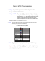
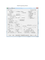
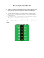
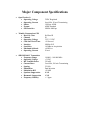
RTrak-HAB
Integrated High Altitude Balloon
APRS Tracker/Telemetry Payload
User’s Manual
Revision A
Written By: Jason Rausch KE4'YV
Copyright 2011 RPC Electronics, LLC
Table of Contents
1.
2.
3.
4.
5.
6.
Introduction and Acknowledgments
Package Contents
Device Overview and Specifications
Connections
Getting Started
Basic APRS Programming
• Callsign
• Icon
• APRS Path
• Beacon Rate
7. Telemetry/Control Header
8. Dual-Frequency Operation
9. Major Component Specifications
• OpenTracker 1+
• M'5010HS GPS Chipset
• MX146LV VHF Transmitter
Introduction
Thank you for purchasing an RTrak-HAB! We are pleased that you have decided to
make it part of your amateur radio equipment and hope that it will serve you well for
many years to come. Please take some time to read through this manual and familiarize
yourself with the functions of your new RTrak-HAB and how to operate it properly.
Acknowledgments
Special thanks to the following people for helping make the RTrak-HAB possible:
Barry Sloan VE6SBS
James Ewen VE6SRV
Scott Miller N1VG
Shaena Hicks KI4UDD
Package Contents
•
Your new RTrak-HAB comes with everything required to get started.
Included Items:
• RTrak-HAB APRS Tracker
• Embeddable Active GPS Patch Antenna
• DB9 Serial to Header Programming Cable
• CD Containing this manual and specification sheets on key components
Device Overview and Specifications
•
The RTrak-HAB is the first APRS tracker designed specifically for the high
altitude balloon community. We have worked closely with HAB enthusiasts to
include all of the features needed for a truly versatile payload.
OpenTracker 1+:
The data modem section of the RTrak-HAB is based on the SMT
OpenTracker 1+ platform. The OpenTracker was designed and
programmed by Scott Miller N1VG of Argent Data Systems. The
OT1+ platform is fully open source and a perfect match for the
RTrak-HAB tracker. Firmware upgrades are free for download.
Compernicus GPS: The GPS receiving chipset used in the RTrak-HAB. This GPS is a
Sirf-Star III receiver with a fast <60 sec cold start lock time,
measures only 20mm x 20mm in size and runs on a 3.3V operating
voltage. The primary reason for using this GPS is the ability to
track ABOVE 60,000 feet in altitude.
MX146LV TX:
The MX146LV VHF transmitter is a fully programmable 350mW
transmitter and is frequency agile from 144-148 MHz. This
module is temperature compensated for stabilization and makes it
perfect for an HAB environment where constantly changing
ambient temperatures can cause less capable transmitters to drift
off of frequency.
Connections
Power
The RTrak-HAB can be powered with any 5.5-12 VDC source. The LDO (Low Dropout
Regulators) used allow for the tracker to be powered from battery for lightweight
payloads.
The connector is a three position solder pad connector suitable for direct soldering or a
pin header for quick disconnect.
GPS RF
The GPS RF connection is a standard polarity, SMA female RF connector suited to mate
with the included GPS active patch antenna. Be sure to tighten antenna connector finger
tight. DO NOT use a wrench to torque the connector tight. This is not needed and risks
damage to the connector or main RTrak-HAB board.
Radio RF
The radio RF connection is a standard polarity, SMA female RF connector. Be sure to
tighten antenna connector finger tight. DO NOT use a wrench to torque the connector
tight. This is not needed and risks damage to the connector or main RTrak-HAB board.
Programming Port
The programming port is a four pin header that mates with the included serial
programming cable. Remove the shorting block when attempting to plug the serial cable
in for programming. Ensure the unused contact of the plug is on the “D” pin.
Important: When the RTrak-HAB is not being programmed, the included jumper block
must be in place over the first two pins marked “D” and “R”, in order for the GPS data to
be passed to the OpenTracker 1+!
Power/RF Connection End
Getting Started
•
Getting started is easy with the RTrak-HAB.
1. Connect power, VHF antenna and GPS antenna.
2. Install the programming software included on the RTrak-HAB User’s CD on any
3.
4.
5.
6.
computer with a 9 pin serial port. Note: Some USB>Serial adapters have been
reported to work with this software. Use at your own risk.
Ensure that power to RTrak-HAB is REMOVED.
Remove the jumper block and connect the programming cable to the RTrak-HAB’s
programming port and the computer’s serial port.
Plug power into the RTrak-HAB.
Start up the RTrak programming software: rtrak-prog.exe. You will see a window
like this:
7. Select the appropriate com port and click Connect.
8. If the software properly reads the RTrak-HAB, the connect window will close and
open up a configuration window containing all of the current settings.
•
When you get to this point, proceed with the following page of Basic APRS
Programming instructions.
Basic APRS Programming
•
Callsign: Use your FCC assigned Amateur Radio callsign for this field
Examples: KE4NYV KI4UDD N1VG
•
Callsign with SSID: The use of an SSID can aid in the multiple use of a single
callsign. The SSID ID will be designated by a dash (-) sign
and a number of 1-15. These SSIDs typically have specific
meaning, so check with your local APRS users for the
SSID that is appropriate for a non-receiving APRS tracker.
Examples: KE4NYV-15 KI4UDD-12 N1VG-9
•
Icon: The icon symbol will tell any receiving station what icon to use when
displaying your position on an APRS map.
Common APRS Icon Symbols
Car
Truck
Van
18 Wheeler
Bike
Hiker
Ambulance
Jeep
RV
Airplane
Boat
•
/>
/k
/v
/u
/b
/[
/a
/j
/R
/’
/Y
Path: The path is used to route your packet as far as you would like it to go,
within reason.
Important! Due to the ability for a VHF signal to travel far at a high altitude, it
is recommended that either a path of WIDE1-1 or no path is used when using the
tracker for high altitude operations.
Beacon Rates: The RTrak-HAB is capable of two beacon schemes.
1. Static Beacon – This method uses a pure timing scheme to beacon at a
constant rate set in programming. This rate cannot be changed unless the
configuration software and cable are used to make the change.
The static beacon rate is set in seconds, meaning 30 = 30 seconds, 60 = 1
minute and so on. A typical static beacon rate is 3-5 minutes.
2. SmartBeaconing™ – This method uses the current GPS data to determine
when to beacon and how often.
There are two main elements to the SmartBeaconing™ algorithm:
•
•
Speed-Adjusted Beacon Rate – Depending on your travel speed, the
beacon rate is either increased or decreased. When traveling faster, the
tracker is covering more ground and beacons more often. When traveling
slower or stopped, the beacon rate is less often since it is not moving far or
may be sitting still.
Cornerpegging – While moving, the SB algorithm is constantly
monitoring the heading of travel. When this degree of heading has
changed past a certain threshold, it triggers a beacon to indicate either a
long steady curve or a direct turn around a corner. The result is a much
more defined track.
•
After all settings have been made, the last step is to write the configuration back to
the RTrak-HAB. Click the “Write” button located in the bottom right of the
configuration window. When the software is completed loading the settings, you will
be asked to click the “OK!” button. The software returns to the main configuration
screen where it can be exited.
•
Power down the RTrak-HAB by removing power from the power connection.
Remove the programming cable, replace the jumper block and power the unit back up
for normal operation. You are now ready to put your RTrak-HAB into service.
'OTE: Any additional settings can be found in the OpenTracker manual, included on
the RTrak-HAB User’s CD
Default Programming Window
Telemetry/Control Header
•
The RTrak-HAB employs a full telemetry and controls package as part of the tracker
payload. All ADC raw values are reported in the payload of the APRS packet.
•
The ADC (Analog to Digital Converter) channels can accept any analog voltage
between 0-5VDC. These channels have on-board 3.3K pull-up resistors and 0.1uF
decoupling capacitors.
The GPO (General Purpose Output) channels can control numerous devices during
flight. GPO 0-2 switches ground. GPO 3 switches +5VDC
•
Important! As of writing this document (4/15/2011) the GPO’s are not yet implemented
in firmware. This will be added soon and this document will be updated to reflect that
change.
Telemetry/Control Header Pinout
Dual-Frequency Operation
•
The RTrak-HAB is capable of operating on two independent VHF frequencies when
in flight. This is accomplished by editing the frequency information in the
configuration software.
1. The first step is to read the tracker’s current programmed profile with the
configuration software.
2. Next, click on the “Freq” button to open up the editing window.
3. The frequency editor window will open up and have defaults loaded in the slots.
4. There are eight total frequency slots provided, but only two can be used at any given
time. Normally, this would be slot 1 and slot 2. Use the selection dots (also known
as “radio buttons”) to assign a frequency slot to the primary and secondary channels.
Primary Channel is the default frequency used on power up and is controlled by the
beaconing timing/scheme selected on the primary configuration window.
Secondary Channel is used only at the specified beacon rate typed into the “Use
secondary every” box.
The example showed above will beacon on the primary frequency based on your
beacon timing/scheme selected on the main page. The secondary frequency will be
beaconed every 5 beacons on the main frequency. This gives you a 5:1 beacon ratio.
Important! If SINGLE frequency operation is desired, set the primary AND secondary
selection dots to slot 1. Also, make sure than the “beacon secondary every” box has a
zero (0) typed into it. This will disable any dual-frequency options.
Major Component Specifications
•
•
•
OpenTracker 1+
• Operating Voltage
• Operating Current
• Modes
• Format
• GPS Interface
5VDC Regulated
8 mA Idle, 20 mA Transmitting
1200 bps AFSK
APRS Standard
NMEA 4800 bps
Trimble Compernicus GPS
• Receiver Class
• Channel
• Operating Voltage
• Cold Start Lock Time
• Interface
• Sensitivity
• Maximum Altitude
• Operating Current
Sirf-Star III
20
3.25-3.3 VDC
>30 Second
NMEA-0183
-145dBm at Acquisition
+60K Feet
30 mA
SBR MX146LV Transmitter
• Frequency Range
• Operating Voltage
• RF Transmit Power
• Current Draw
• Spacing
• Modulation
• Modulation BW
• Spurious Suppression
• Harmonic Suppression
• Frequency Stability
144.000 – 148.000 MHz
+5 VDC
350 mW
2 mA Idle, 300 mA Transmitting
2.5 kHz
Dual Injection
>20 kHz
80 dB
45 dB
+/- 5ppm