1
MR350MKII
Data Collection Terminal
Programming Reference Manual
Unitech Electronics Co., Ltd.
September 2001 V1.2
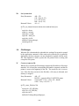
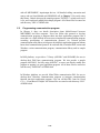
Introduction
This manual is a hand book for whom intend to develop an application program on
MR350MKII and Host computer or MS-DOS based PC. It will introduce the I/O function
calls, DOS Manager function calls, File Manager function calls and Host ESC commands.
For your easy understanding, source code of the two sample programs are listed in appendix
D and E.
All the programs mentioned in this manual are contained in a 3.5” MS-DOS format demo
diskette. If you doesn’t have the diskette, please contact your local unitech authorized
dealer.
1-1
Table of Contents
Table of Contents...................................................................................................................1-2
1.
System Kernel............................................................................................................1-6
1.1.
1.2.
1.3.
1.4.
Application Programming Interface.................................................................................. 1-6
Keypad Subsystem ............................................................................................................ 1-7
Display Subsystem............................................................................................................ 1-7
Communication Subsystem............................................................................................... 1-8
1.4.1. Point to point mode.................................................................................................... 1-8
1.4.2. Multi-point mode....................................................................................................... 1-8
1.5.
Real time clock subsystem ................................................................................................ 1-8
1.6.
Relay output and Digital input subsystem.......................................................................... 1-8
1.7.
Bar code / Magnetic stripe / Proximity / ICC .................................................................... 1-9
1.8.
Download Program in Point-to-point mode....................................................................... 1-9
1.9.
Download Program in Multi-point mode......................................................................... 1-10
2.
Data Structure ..........................................................................................................2-14
2.1.
2.2.
2.3.
Device Control Table...................................................................................................... 2-14
Type Definition .............................................................................................................. 2-14
Barcode Control Table.................................................................................................... 2-15
2.3.1. Type Definition........................................................................................................ 2-15
2.4.
Communication Control Table of Host port..................................................................... 2-16
2.4.1. Type Definition........................................................................................................ 2-16
2.5.
Terminal Control Table (available for host port only) ..................................................... 2-17
2.5.1. Type Definition........................................................................................................ 2-17
3.
I/O Function Calls ....................................................................................................3-20
LCD Display INT 10H.................................................................................................. 3-20
Clear screen............................................................................................................. 3-20
Set cursor type ......................................................................................................... 3-20
Set cursor position ................................................................................................... 3-20
Get cursor position................................................................................................... 3-21
Scroll screen ............................................................................................................ 3-21
Enable/disable LCD Backlight INT 21H ................................................................. 3-21
3.2.
Communication Environment Setup ............................................................................... 3-22
1C
Select COM1 or COM2 as the host port ................................................................... 3-22
1C
Set host port protocol ............................................................................................... 3-23
1C
Set serial port flow control ....................................................................................... 3-23
19
Set COM1 port as RS485 or modem ........................................................................ 3-24
3.3.
Host Port for Multi-point Protocol I/O (INT21H) ........................................................... 3-24
1C
Setup multi-point address......................................................................................... 3-24
1C
Set polling timeout duration..................................................................................... 3-24
5F
Read host port.......................................................................................................... 3-25
60
Output data.............................................................................................................. 3-25
61
Check if Busy-port ................................................................................................... 3-25
3.4.
Serial I/O for RS-232 and RS-485................................................................................... 3-26
RS-232 port serial I/O using INT 34H................................................................................ 3-26
01
Input data ................................................................................................................ 3-26
02
Output data.............................................................................................................. 3-27
3.1.
00
01
02
03
04
1A
1-2
03
Enable RS-232 port.................................................................................................. 3-27
04
Disable RS-232 port................................................................................................. 3-27
00
Set Communication parameters................................................................................ 3-27
05
Set RTS signal of RS-232 port ................................................................................. 3-29
06
Read CTS signal of RS-232 port .............................................................................. 3-29
RS-485 port serial I/O using INT 33H............................................................................... 3-29
01
Input data ................................................................................................................ 3-29
02
Output data.............................................................................................................. 3-30
03
Enable RS-485 port for serial I/O............................................................................. 3-30
04
Disable RS-485 port for serial I/O............................................................................ 3-30
00
Set Communication parameters................................................................................ 3-31
05
Open RS-485 multi-bus to send out data .................................................................. 3-32
06
Close RS-485 multi-bus (release RS-485 bus) .......................................................... 3-33
3.5.
Relay Output / Digit Input / Buzzer / LED Indicator ....................................................... 3-34
Set LED indicator ON/OFF INT 09H .................................................................................. 3-34
Read Photo Coupler Level state INT 08H.............................................................................. 3-34
Activate/Deactivate Relay ports INT 09H ............................................................................ 3-35
1A
Buzzer On/Off INT 21H ......................................................................................... 3-35
1A
Set buzzer volume INT 21H..................................................................................... 3-36
1B
Get Security state INT 21H ..................................................................................... 3-36
1B
Alarm On/Off INT 21H ........................................................................................... 3-36
54
Buzzer volume control with user-defined frequency and time INT 21H ................... 3-37
Buzzer volume control with predefined frequency and time INT 35H .................................. 3-37
3.6.
Internal/ External reader Port: INT 21H ........................................................................ 3-38
51
Enable/Disable External reader port......................................................................... 3-38
18
Set external slot reader (only available for Barcode and Magnetic reader) ................ 3-38
50
Read data from external reader(only available for Barcode and Magnetic reader)..... 3-39
52
Read Internal port.................................................................................................... 3-39
53
Enable/disable Internal reader.................................................................................. 3-40
1F
Enable/Disable the Decoder of Wiegand Format (Proximity reader) ......................... 3-40
1F
Get Decoder status of Wiegand Format (Proximity reader)....................................... 3-41
1A
Assign barcode or magnetic stripe input of Internal reader....................................... 3-41
1F
Enable the decoding of a barcode symbology............................................................ 3-42
3.7.
Miscellaneous: INT 21H ................................................................................................ 3-42
1A
Check lithium battery level ...................................................................................... 3-42
1B
Get Address ID of the terminal ................................................................................ 3-43
25
Set interrupt vector .................................................................................................. 3-43
35
Get interrupt vector.................................................................................................. 3-43
36
Get free disk cluster ................................................................................................. 3-44
1A
Enable/disable system key-pressing commands: Warm start, Invoke user command menu,
Invoke supervisor mode ......................................................................................................... 3-44
1E
Change the Keyboard map ....................................................................................... 3-44
3.8.
DOS Manager................................................................................................................. 3-46
01
Read stdin (wait if no key) and write it to stdout ...................................................... 3-46
02
Write stdout ............................................................................................................. 3-46
03
Read stdaux (COM2 RS-232 port) ........................................................................... 3-47
04
Write stdaux (COM2 RS-232 port) .......................................................................... 3-47
06
Read / Write stdin or return 0 if none is ready.......................................................... 3-47
07
Read stdin (wait if no key) ....................................................................................... 3-48
08
Read stdin (wait if no key) ....................................................................................... 3-48
09
Write character string to stdout ................................................................................ 3-48
0A
Keyboard buffer input .............................................................................................. 3-49
0B
Keyhit check............................................................................................................ 3-49
2A
Get System date ....................................................................................................... 3-49
1-3
2B
2C
2D
3.9.
3C
3D
3E
3F
40
41
42
43
56
48
49
4A
4.
Set System date........................................................................................................ 3-50
Get System clock ..................................................................................................... 3-50
Set System clock ...................................................................................................... 3-51
File Manager .................................................................................................................. 3-51
Create or truncate file .............................................................................................. 3-51
Open file.................................................................................................................. 3-52
Close file ................................................................................................................. 3-52
Read file .................................................................................................................. 3-53
Write file ................................................................................................................. 3-53
Delete file ................................................................................................................ 3-54
Move file pointer ..................................................................................................... 3-54
Get file attribute....................................................................................................... 3-55
Rename a file........................................................................................................... 3-55
Allocate specified number of paragraphs memory .................................................... 3-56
Free allocated memory ............................................................................................. 3-56
Modify allocated block............................................................................................. 3-56
Host ESC Commands ..............................................................................................4-58
4.1.
General Control Commands ........................................................................................... 4-58
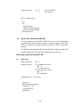
17.
Get terminal ID (ESC R) ................................................................................... 4-61
This commcand can get terminal ID. The default terminal ID is "MR350" ...................... 4-61
18.
Get terminal ID and version no (ESC v)............................................................ 4-61
This commcand can get terminal ID and version no. The default terminal ID is "MR350 V4.xx".
....................................................................................................................................... 4-61
4.2.
Configuration Commands............................................................................................... 4-61
4.3.
File Transfer Commands ................................................................................................ 4-63
4.4.
Multipoint Protocol......................................................................................................... 4-63
4.4.1. Protocol Operation................................................................................................... 4-65
4.4.2. Commands............................................................................................................... 4-66
ESC 0 - Application data ................................................................................................ 4-66
ESC A - Soft Reset, Restart, or Abort.............................................................................. 4-67
ESC B - Enable/disable the decoding of barcode symbologies:....................................... 4-67
ESC C - Write communication configuration table to MR350MKII................................. 4-67
ESC D - Read directory of RAM disk to host................................................................... 4-68
ESC D/ROM - Read directory of Flash ROM to host ...................................................... 4-68
ESC E - Erase a file from the MR350MKII directory ...................................................... 4-68
ESC F - Disable UPS battery to supply power ................................................................ 4-68
ESC G - Get MR350MKII's RAM size ............................................................................. 4-68
ESC G/ROM - Get MR350MKII's Flash ROM size.......................................................... 4-69
ESC H - Hard Reset and initiate power on test ............................................................... 4-69
ESC I - Get filename of current executing program ........................................................ 4-69
ESC J - Check if file existed or not ................................................................................. 4-69
ESC K - Set keyboard locking......................................................................................... 4-70
ESC L - Transfer file to MR350MKII .............................................................................. 4-70
ESC M - Write date and time to MR350MKII.................................................................. 4-70
ESC O - Set auto-execution program .............................................................................. 4-70
ESC P - Set supervisor password (maxi. 8 characters) .................................................... 4-71
ESC R - Terminal ID ...................................................................................................... 4-71
ESC T - Write terminal configuration table to MR350MKII ............................................ 4-71
ESC U - Transfer file from MR350MKII ......................................................................... 4-71
ESC V - Write device configuration table to MR350MKII............................................... 4-71
ESC v - Get Terminal ID and version no......................................................................... 4-72
ESC X - Start program execution.................................................................................... 4-72
1-4
4.5.
ESC Commands Added for MV1100 Fingerprint Module .......................................... 4-72
4.5.1. Get Template List (ESC $D) ................................................................................ 4-72
4.5.2. Erase Template ( ESC $E) .................................................................................... 4-74
4.5.3. Enroll and Store Template on MR350 MKII ( ESC $F )......................................... 4-74
4.5.4. Enroll and Store Template on MV1100 ( ESC $G ) ............................................... 4-75
4.5.5. Verify Template ( ESC $H )................................................................................... 4-75
4.5.6. Verify ID ( ESC $I )............................................................................................... 4-76
4.5.7. Download Template ( ESC $L) .............................................................................. 4-76
4.5.8. Set Globe Threshold ( ESC $S).............................................................................. 4-77
4.5.9. Get Globe Threshold ( ESC $S) ............................................................................. 4-77
4.5.10.
Upload Template ( ESC $U)............................................................................ 4-78
4.5.11.
Get Version ( ESC $V) ................................................................................... 4-78
4.6.
ESC Commands Added for Flash Memory Features......... Error! Bookmark not defined.
5.
How to to programming ..........................................................................................5-80
5.1.
Programming MR350 MKII ........................................................................................... 5-80
5.1.1. Programming by JobGen PRO ................................................................................. 5-81
5.1.2. Programming by C/C++........................................................................................... 5-81
5.2.
Programming communication program........................................................................... 5-82
5.3.
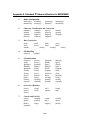
Contains of the Demo Disk ............................................................................................. 5-83
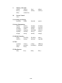
Appendix A. Standard C Libraries Routine for MR350MKII ...............................................5-84
1-5
Chapter 1. System Kernel
1.
System Kernel
This chapter is used to introduce the system kernel of MR350MKII. Where the
system kernel is divided into six subsystems to service application programming
interface, keyboard input, LCD display, communication I/O, Real Time Clock, Relay
output/Digital input and Barcode wand/Magnetic stripe/Proximity reader.
1.1.
Application Programming Interface
The MR350MKII kernel includes three basic modules: device driver, file
manager and DOS manager. The programmer can design the application
programs by calling those available functions just like that in the PC DOS
environment.
The ROM based operating system of the terminal provides emulated
MS/DOS function calls. The calling and parameter passing conventions are
identical to that of MS/DOS. The detailed description of supported
functions of the Terminal's subsystems, I/O interface, DOS manager and File
manager is defined in later chapters.
The software to be run on MR350MKII may be programmed by using
Microsoft C 5.1 and later version, and the IBM PC macro assembler version
1.0 and later version. Transaction data can be processed interactively with
the computer or stored in a file.
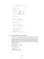
NOTE in using Microsoft C:
When program execution area assigned less than 64K (see section 4.3) and
a program with size more than 64K is invoked to run. A run time error
message, "Not enough space for environment", will be shown. In this case
add following statement in main:
/* mypgm.c */
_setenvp()
{
}
main()
{...
...
...
}
and link with: >LINK /NOE mypgm
1-6
1.2.
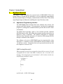
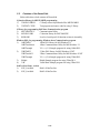
Keypad Subsystem
The keypad subsystem scans the key matrix, converts the scan code to its
associated key value, and stores the value in the input buffer of keyboard for
program utilization. Note that the [SHIFT] key is not stored into the buffer,
it is used to distinguish the alphabetic and numeric mode of associated key
position and provide an alternative key code. The following table shows the
key values of each key.
Table of Key Values
Value
Key
Value
Key
Value
41H
O
4FH
[SP]
20H
42H
P
50H
0
30H
43H
Q
51H
1
31H
44H
R
52H
2
32H
45H
S
53H
3
33H
46H
T
54H
4
34H
47H
U
55H
5
35H
48H
V
56H
6
36H
49H
W
57H
7
37H
4AH
X
58H
8
38H
4BH
Y
59H
9
39H
4CH
Z
5AH
[E]
0DH
4DH
+
2BH
[C]
08H
4EH
2DH
2EH
.
Key
A
B
C
D
E
F
G
H
I
J
K
L
M
N
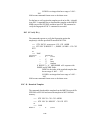
1.3.
Key
F1/?
?
F2/??
F3/?
?
F4/?
F5/*
?
F6/?
F7/?
Value
86H
87H
88H
89H
8AH
8BH
8CH
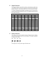
Display Subsystem
This subsystem provides the interface functions: Display character, Display
string, Set cursor position, and Clear screen display. The display coordinates
are organized as follows:
Min
Min
Max
Max
Row
Col
Row
Col
0
0
1
15
The origin (0,0) is always at the upper left hand corner.
1-7
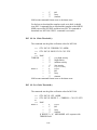
1.4.
Communication Subsystem
The MR350MKII terminal communication subsystem consists of
1) point-to-point connection mode and
2) multi-point connection mode for network processing.
1.4.1. Point to point mode
Either RS-232 or RS-485 port can be used in point-to-point mode
when it is set as serial port. Each port can be configured, input data
and output data by DOS call. Nevertheless to transfer files, a Kermit
server can be invoked by selecting option “3) COM” in user
command menu or typing ”COM” in the Ready mode and a Kermit
utility should also run on the Host side in order to make the data
communication.
1.4.2. Multi-point mode
Either RS-232 or RS-485 port can be also used in multi-point mode
by Multi-protocol (define by Unitech) when it is set as Host port.
While RS-485 port is assigned to serve multi-point mode, up to 32
terminals can be accessed through one channel, On the other hand,
while RS-232 is selected, the number of accessible terminals is
limited by the number of available RS-232 ports on the host
computer. There is also a multi-point communication protocol built
in the MR350MKII for data communication of a multi-point
networking.
1.5.
Real time clock subsystem
This subsystem allows the program to set and read system date and time of
the MR350MKII.
1.6.
Relay output and Digital input subsystem
The MR350MKII supports two contact relay ports and four photocoupler
input ports for digital signal input/output control, where pin #11/12 and pin
#13/14 can also be assigned to RS-232 port and barcode scanner by setting
of jumpers J1 to J6 (refer to MR350MKII Technical Reference Manual).
1-8
1.7.
Bar code / Magnetic stripe / Proximity / ICC
The MR350MKII has two ports for connecting different reader Internal
reader and External reader.
External reader port is dedicated for bar code reading by a bar code wand,
CCD, or laser diode scanners, and the terminal supports reading of Code 39,
Code 128, Codabar, Interleaved 2 of 5, UPC and EAN.
NOTE:
The CCD and laser diode scanner are only supported while connected
through internal reader port. If the terminal block port #3 is set as
scanner port, it can support barcode wand, slot reader , magnetic stripe
reader and proximity reader.
The Internal reader, as badge reader port, is mainly designed for
connecting a barcode slot reader, magnetic stripe reader, proximity
reader(wiegand interface) or smart card (ICC) reader. The terminal supports
the reading of single track 1, 2 or 3 magnetic card stripe.
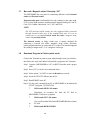
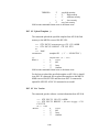
1.8.
Download Program in Point-to-point mode
Connect the Terminal in point-to-point mode through serial port interface,
then follow the steps listed below to download a program to the Terminal:
Step 1. Connect a MR350MKII to a PC via RS232 interface with a proper
cable.
Step 2. Press [F5/*] to invoke user command menu.
Step 3. Select option “3) COM” to enter the Kermit serve mode.
Step 4 Insert the UTILITY diskette into the PC.
Step 5. Run KERMIT in the PC.
Step 6. Use the send command from PC to MR350MKII to download the
UTILITY program, 350TEST.EXE.
?
MS-Kermit>SEND <file name>
Downloads an execution file from the PC disk to
MR350MKII RAM area. (program)
?
MS-Kermit>GET <file name>
to
Gets a collected data file from MR350MKII RAM area (data)
PC disk.
?
MS-Kermit>REMOTE DIR
1-9
(
Displays all of the files which are stored in the MR350MKII
Program as well as data file)
?
MS-Kermit>REMOTE DEL <file name>
Deletes a program or data file in the MR350MKII.
Step 7. Press [SHIFT] in conjunction with [F5/*] on MR350MKII to exit
from Kermit server mode to Ready mode.
Step 8. Select option “1) RUN” in user command menu and press [F7/? ] key
to step through the available downloaded executable object program,
then press [E] to confirm for choosing 350TEST.EXE to run, or,
type the filename (i.e. 350TEST) directly under system Ready
prompt. This program allows you to scan barcode data and send data
from the MR350MKII to the PC.
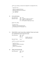
1.9.
Download Program in Multi-point mode
A sample program, 485COM.EXE, in the UTILITY disk is for multi-point
mode environment testing. Please note in multi-point mode each terminal
should be assigned a unique address ID and consistent communication
parameters with the PC.
NOTE: Following instructions use Host port to serve multi-point mode.
1) If Host port is RS232, directly connect to RS232 port between PC and
MR350MKII
2) If Host port is RS485. Install an RS-485 interface card or an RS232/422
converter to the PC. And cabling the network trunk from RS485
interface to MR350MKII via RS485 port (note a twist-pair cable with 22
or 24 AWG should be used).
3) Set communication parameters including address ID on each
MR350MKII properly. (The default values are, 9600 bps, non-parity, 8
data bits, 1 stop bit, address ID ‘A’)
4) Power up the PC and all terminals.
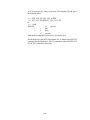
5) Run the test program, 485COM.EXE, on the PC.
CRT screen shall appear the following message:
Terminal type 1>350/360 2>700/870/860:
Typing “1” for selecting MR350,
COM(1-4)?:
Typing “1” for selecting COM1, “2” for COM2.
1-10
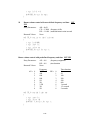
6) Then, the screen will display:
V2.1 COM2 Address: ESC=1 NAK=3 PARA=9600,1,8,NONE
0.Send
1.Poll
A.Stop
B.BarT
C.ComT
D.DIR
E.Del
F.ExeSize
f.Font
G.Memory
H.Reset
I.ExFile
J.Exist
K.Keypad
k.Kermit
L.Dnload
M.Time
N.Buzzer
O.Auto
P.Passwd
Q.UplMode R.TrmID
T.TrmT
U.Upload
V.DEV_T
X.Exec
3.brk
5.ChgAdr
9.Loop
@.Modem
?.320
~.UPS off
F1.Addr
F2.Comm_P F3.Retry
F4.Disp.
F5.Shell
F6.Pkt size : Select:
Item
0).
Send a string of characters as message to MR350MKII.
1).
Polling data from each terminals.
A).
Warm start means putting all connected terminals to ready
mode, previously running program is stopped.
B).
Set enable/disable the barcode symbologies
C).
Set communication control table.
D).
Remote read the files existed on MR350MKII ram disk.
E).
Remote delete a specified file which existed on ram disk.
F).
Change RAM size of executable area (Not available on
MR350MKII).
f).
Change font size. (Not available on MR350MKII)
G).
Get all connected terminals current total RAM size,
execution area size, and free size.
H).
Cold start means initializing the system parameters of
all connected terminals to factory default values.
I).
Get filename of current running program.
J).
Check if specified file existed or not.
K).
Set keypad Lock / Unlock / Partial lock. (Not available on
MR350MKII)
k).
Enter Kermit server mode (Not available on MR350MKII)
L).
Download a program or data file to MR350MKII.
M).
Set connected terminal’s date and time.
1-11
N).
Set beeper's volume.
O).
Set a executable object program to be started up
automatically after power-up.
Q).
Inquire Uploading status (Not available on MR350MKII)
R).
Change terminal's ID.
T).
Set terminal control table.
U).
Upload a program or data file from MR350MKII.
V).
Set device control table.
X).
Remote run means that starting up an pre-downloaded
executable object program on the terminal.
3).
Set power saving (Not available on MR350MKII)
5).
Set connected terminal address.
9).
Loop back testing.
@).
Dumping terminal and Modem control
?).
MR320's setting (Not available on MR350MKII)
~).
Disable UPS
F1).
Set available terminal address to be communicated
F2).
Set PC's communication parameter
F3).
Set time period of Time-out/ NAK re-try / ACK
F4).
Debug mode (display whole received and sent data)
F5).
Go to DOS shell
F6).
Set communication packet size (For debug only)
[ESC]. Exit 485COM.EXE and back to DOS prompt.
7) Select item F1) to key in the address of all connected terminals or some
terminals to be tested; for example, if there are three terminals connected
with address A, B, C, respectively, type “ABC”.
8) Select item L) to download program 350TEST.EXE. This procedure
will be repeated till all designated terminals have been downloaded.
9) Select item X) and input program name, 350TEST, to start up the
program on all designated terminals in step 7.
1-12
10) Select item 1) to start getting data, PC screen will appear "… ." indicating
there is no data collected. If any of those terminals starting input data by
scanning bar code label, PC screen will show as below:
A (nn): XXXXXX
The first character mean terminal address. Where XXXXXX is the
data scanned from all connected barcode input devices or magnetic
striper reader and NN is its data length.
10) Select item 0). to send message to terminals. Key in whether string
according to PC screen instruction, and the string pattern will then be
displayed on the terminal's LCD as Application data:XXXXX where
XXXXX is the string you keyed in from PC keyboard.
11) You may also select H) and A) to test the Cold-start and Warm-start
functions. Or press [ESC] key to end this program.
1-13
Chapter 2. Data Structure
2.
Data Structure
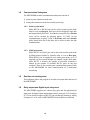
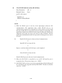
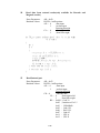
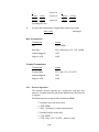
MR350MKII system control data structures are outlined in the following diagram.
The system kernel uses the File Allocation Table (FAT), File Handle Table (FHT),
Communication Control Table, Device Control Table and Key Alias Table. The
following sections will describe each one of these control tables. The description
includes a "typedef" part and the "default" values of the table.
Terminal Application
EXEC
Terminal Control Table
Device control table
Kernel
File Allocation Table
2.1.
File Handle Table
Comm Control Table
RS232&RS454
Device Control Table
The device control table contains MR350MKII peripheral configuration information
including the barcode scanner port, the badge reader port, LCD display, keyboard
and buzzer output. The barcode scanner is controlled by a separate data structure
and barcode control table, to be discussed later.
2.2.
Type Definition
typedef struct {
BYTE scanner;
BYTE badge;
BYTE lcd_backlight;
BYTE buzzer;
BYTE keylock;
BYTE buzzer_volume;
} DEV_CONFIG;
scanner:
'N'
'F'
= enable scanner port
= disable scanner port (default)
badge
'B'
= enable badge port for barcode slot reader (default)
2-14
'M'
'D'
lcd_backlight: 'N'
'F'
= set LCD backlight ON
= set LCD backlight OFF (default)
buzzer:
'N'
'F'
= set buzzer ON (default)
= set buzzer OFF
keylock:
'N'
'K'
'P'
= set keyboard Unlock (default)
= set keyboard Locked
= set keyboard Partial Locked
buzzer_volume:
2.3.
= enable badge port for magnetic card reader
= disable badge port
‘0’
'5'
'9'
= Low volume (default)
= Middle volume
= High volume
Barcode Control Table
The MR350MKII supports decoding software to automatically discriminate
bar code symbologies: Code 39, Code 39 Full ASCII, EAN-8, EAN-13,
UPC-A, UPC-E, Code 128, Codabar and Interleaved 2 of 5.
2.3.1. Type Definition
typedef struct {
BYTE code39;
BYTE i2of5;
BYTE codabar;
BYTE ean_upc;
BYTE code128;
} BARCODE_CONFIG;
code39:
'N'
'F'
= Enable barcode decoding of Code 39(default)
= Disable barcode decoding of Code 39
i2of5:
'N'
'F'
= Enable barcode decoding of Interleaved 2 of 5
(default)
= Disable barcode decoding of Interleaved 2 of 5
codabar:
'N'
'F'
= Enable barcode decoding of codabar(default)
= Disable barcode decoding of Codabar
ean_upc:
'N'
'F'
= Enable barcode decoding of UPC/EAN
(default)
= Disable barcode decoding of UPC/EAN
'N'
= Enable barcode decoding of Code 128 (default)
code128:
2-15
'F'
2.4.
= Disable barcode decoding of Code 128
Communication Control Table of Host port
The communication control table is applicable to configure the host port of
the MR350MKII.
The communication control table specifies all communication parameters
between the host system and the MR350MKII. When a hard reset command
is issued via keypad input or host command sequence the default
communication parameters are restored. The host system may then configure
most MR350MKII parameters by issuing host command sequences. The
host command sequences will be introduced in this manual.
2.4.1. Type Definition
typedef struct {
BYTE baud_rate;
BYTE stop_bit;
BYTE data_bit;
BYTE parity;
BYTE protocol;
BYTE address;
WORD timeout;
} COM_CONFIG;
The MR350MKII terminal communicates with the host via the host
port. The communication baud rate may be programmed from 110
to 38.4K baud (bits per second).
baud_rate:
'0'
'1'
'2'
'3'
'4'
'5'
'6'
'7'
'8'
'9'
= 110 bits per second
= 150
= 300
= 600
= 1200
= 2400
= 4800
= 9600 (default)
= 19200
= 38400
stop_bit:
'1'
'2'
= one stop bit (default)
= two stop bits
data_bit:
'7'
'8'
= 7 data bits
= 8 data bits (default)
parity:
'N'
= None parity (default)
2-16
protocol:
address:
'O'
'E'
= Odd parity
= Even parity
'M'
'F'
'A'
= Multipoint (default)
= None protocol
= terminal address ID for Multipoint mode
(default)
Each MR350MKII has to be assigned a unique
communication address when it is used in a
Multipoint environment. The address is used by a
host or concentrator to perform polling functions.
Characters 'A'-'Y' and '0'-'6' are used for assigning an
address ID of each terminal.
timeout:
'02'
= polling timeout two cycle periods
(default).
'02'-'FF' in hex format.
The value of this setting is specified for the
communication timeout. If the MR350MKII does not
receive a response from the host system within the
number of timeout cycle periods, the MR350MKII
regards the communication as unsuccessful and the
transmission is then aborted. If the timeout value is
set to zero, no timeout check is performed by the
MR350MKII.
2.5.
Terminal Control Table (available for host port only)
The terminal control table is meaningful only if the MR350MKII operation switch is
set to "terminal mode". All other operational modes ignore the terminal control
table.
2.5.1. Type Definition
The terminal control table is defined by the following typedef
TERM_CONFIG. There is only one instance of the
TERM_CONFIG data structure:
typedef struct { char terminal_id[8]; /* terminal id */
BYTE
online;
BYTE
echo;
BYTE
autolf; /* auto LF */
BYTE
mode;
BYTE
linepage; /* line or page block */
BYTE
lineterm; /* line terminator */
2-17
BYTE
pageterm;/* page terminator */
} TERM_CONFIG;
Each MR350MKII "terminal" is identified by an ASCII string. There
can be up to seven characters of a terminal identification. The
identification entry in the TERM_CONFIG table has one more
character space to allow ASCII_Z (hex 0) termination, as in C
language convention.
online:
echo:
'R'
'L'
= set to Remote and transmit data to
the host port (default)
= set to Local and not transmit
'N'
'F'
= Collected data displayed
= Collected data not displayed
Above two variables, TERM_online and
TERM_echo, are used to control
transmission and display of the collected data,
respectively. If TERM_online is set to
Remote the MR350MKII will transmit data
to the host, otherwise it will not transmit. If
TERM_echo is set to Echo collected data will
be displayed on the MR350MKII LCD,
otherwise data will not be displayed.
autolf:
'N'
= set not to append a LF after a CR
'F'
= set to append a LF (default)
This variable instructs the MR350MKII to
append a LF character whenever a CR is
collected from an input scanning device.
mode:
'C'
= set to Character mode
'B'
= set to Block mode (default)
This parameter specifies either character
mode or block mode free-format operation.
The aforementioned form caching operation
is only applicable when the MR350MKII is
set in block mode.
linepage:
'L'
'P'
'B'
= set line block mode (default)
= set page block mode
= set both line and page block modes
The linepage parameter is useful only if mode
has been specified as 'B'.
2-18
lineterm:
designates the termination character of line
block mode (default = null)
pageterm:
designates the termination character of page
block mode (default = null)
2-19
Chapter 3. I/O Function Calls
3.
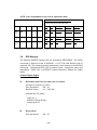
I/O Function Calls
The operating system of the MR350MKII supports BIOS/DOS Function to control
LCD display, Keyboard input, Proximity/Barcode/Magnetic stripe input, Buzzer,
Security alarm, Photo-coupler input, Relay output, and serial port input/output of
RS232 and RS485. The whole C sample program are gathered into library file
"350LIB.C" on Utility Diskette.
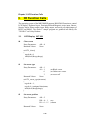
3.1.
LCD Display INT 10H
00
Clear screen
Entry Parameters:
Returned Values:
AH = 0
None
void TL_clrscr()
{
regs.h.ah= 0;
int86(0x10,®s,®s);
}
01
Set cursor type
Entry Parameters:
Returned Values:
AH = 1
AL = 1
0
3
None
;set Block cursor
;set Underscore cursor
;set cursor off
void TL_cursor_type(int status)
{
regs.h.ah = 1;
regs.h.al = (unsigned char)status;
int86(0x10,®s,®s);
}
02
Set cursor position
Entry Parameters:
Returned Values:
AH = 2
DH = 0 ~ 1
DL = 0 ~ 15
None
3-20
;row
;column
void TL_gotoxy(int x,int y)
{
regs.h.ah = 2;
regs.h.dh = (unsigned char)y;
regs.h.dl = (unsigned char)x;
int86(0x10,®s,®s);
}
03
Get cursor position
Entry Parameters:
Returned Values:
AH = 3
DH = 0 ~ 1
DL = 0 ~ 15
;row
;column
void TL_getxy(int *x,int *y)
{
regs.h.ah = 3;
int86(0x10,®s,®s);
*y = regs.h.dh;
*x = regs.h.dl;
}
04
Scroll screen
Entry Parameters:
AH = 4
AL = 0
=1
void TL_scroll(int status)
{
regs.h.ah = 4;
regs.h.al = (unsigned char)status;
int86(0x10,®s,®s);
}
1A
;disable
;enable
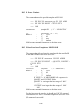
Enable/disable LCD Backlight INT 21H
Entry Parameters:
Returned Values:
AH = 0x1A
BH = 0
AL = 0
1
None
void TL_backlight(int status)
{
regs.h.ah = 0x1A;
regs.h.al = (unsigned char)status;
regs.h.bh = 0;
3-21
;disable
;enable
int86(0x21,®s,®s);
}
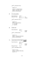
3.2.
Communication Environment Setup
Before placing MR350MKII into the communication environment, you have
to decide:
1) Whether the RS-422/485 port or RS-232 port assigned as host port and
another one as serial port.
2) Set communication protocol for host port. Please note, the protocol for
serial port is always none.
3) If you have installed a internal modem interface. You have to set COM1 as
modem instead of RS485.
The factory defaults for the communication environment are:
Host port: as RS-422/485, multi-point protocol.
Serial port: RS-232, none protocol.
Once you have assigned the protocol to the host port, the MR350MKII’s
system kernel will automatically packing or unpacking the sending or
receiving data according to the selected protocol. On the other hand, since
the serial port has no protocol, you must use INT 34H (RS232) or INT 33H
(RS-422/485) to read or write data character by character.
?? NOTE:
If you want to control the host port I/O service, you must designate
“NONE” protocol for the host port and then using INT 34H or INT 33H to
control I/O for RS232 or RS422/485. The proper function call depends on
which port is assigned as host port(see the next two sections).
1C
Select COM1 or COM2 as the host port
Entry Parameters:
Returned Value:
AH = 1C
BH = 0
AL = 1
2
None
; Select COM1 as host
; Select COM2 as host
?? NOTE:
While one of the COM port is designated as host, the other one is set as
serial port automatically by system.
3-22
void TC_select_host(int status)
{
regs.h.ah = 0x1C;
regs.h.al = (unsigned char)status;
regs.h.bh = 0;
int86(0x21,®s,®s);
}
1C
Set host port protocol
Entry Parameters:
AH = 1C
BH = 1
AL = 2
3
Returned Valued:
None
void TC_protocol(int status)
{
regs.h.ah = 0x1C;
regs.h.al = (unsigned char)status;
regs.h.bh = 1;
int86(0x21,®s,®s);
}
1C
; Multi-point (default)
; None protocol
Set serial port flow control
The system provides three handshaking mode for serial port: XON/XOFF,
CTR/RTS and none. The system default flow control for serial port is ?
ONE”. The CTS/RTS is only available while the RS-232 is designated to
serial port.
Entry Parameters:
Returned Value:
AH = 1C
BH = 2
AL = 0
1
2
None
; None
; XON/XOFF
; CTS/RTS
?? NOTE:
If you want to control the hand shaking flow of serial port, you must set the
flow control as “NONE”.
void TC_flow_ctrl(int status)
{
regs.h.ah = 0x1C;
regs.h.al = (unsigned char)status;
regs.h.bh = 2;
int86(0x21,®s,®s);
3-23
}
19
Set COM1 port as RS485 or modem
This function call is used to set COM1 port as RS485 serial port or modem
when you have the internal modem interface installed. Before you can start
to use modem for communication, you must set COM1 port as modem.
Entry Parameters:
Returned Value:
AH = 19
AL = 0
1
None
; set as RS485
; set as modem
void TC_modem_port(int status)
{
regs.h.ah= 0x19;
regs.h.al= status;
int86(0x21,®s,®s);
}
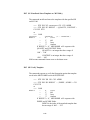
3.3.
Host Port for Multi-point Protocol I/O (INT21H)
1C
Setup multi-point address
Entry Parameters:
Returned Values:
AH = 0x1C
BH = 06
AL = 'A'..'Y','0'..'6'
None
void TC_set_address(char status)
{
regs.h.ah= 0x1C;
regs.h.al= status;
regs.h.bh= 6;
int86(0x21,®s,®s);
}
1C
Set polling timeout duration
Entry Parameters:
Returned Values:
AH = 0x1C
BH = 09
AL = 0-255
None
void TC_time_out(int status)
3-24
;timeout period with base
timeout cycle 80ms
;timeout period is 160ms
when set AL=2; AL=0 for no
timeout
{
regs.h.ah= 0x1C;
regs.h.al= status;
regs.h.bh= 9;
int86(0x21,®s,®s);
}
5F
Read host port
Entry Parameters:
Returned Values:
AH = 0x5F
DS:DX = buffer pointer
AL = 0
;output succeed
1
;no data
int TC_str_I(unsigned char *str,int wait)
{
do {
regs.h.ah=0x5F;
segregs.ds = FP_SEG(str);
regs.x.dx = FP_OFF(str);
int86x(0x21,®s,®s,&segregs);
} while (wait && regs.h.al);
return(regs.h.al);
}
60
Output data
Entry parameters:
Returned Values:
AH = 0x60
DS:DX = buffer pointer
AL = 0
;output succeed
1
;buffer busy now
int TC_str_O(unsigned char *str,int wait)
{
do {
regs.h.ah=0x60;
segregs.ds = FP_SEG(str);
regs.x.dx = FP_OFF(str);
int86x(0x21,®s,®s,&segregs);
} while (wait && regs.h.al);
return(regs.h.al);
}
61
Check if Busy-port
Entry Parameters:
AH = 0x61
3-25
Returned Values:
AL = 0
1
;port is available
;port is busy
int TC_ready(int wait)
{
int i;
do {
regs.h.ah=0x61;
int86(0x21,®s,®s);
} while (wait && regs.h.al);
return(regs.h.al);
}
3.4.
Serial I/O for RS-232 and RS-485
The system allow to the RS-232 and RS-485 to serve serial input/output
(character mode I/O) no matter the port is assigned as host or serial port.
However, if the port is assigned as host, must select “NONE” as its active
protocol.
The INT 34H is dedicated for RS-232 and INT33H is dedicated for RS-485
and the both function calls are functional for host and serial port.
RS-232 port serial I/O using INT 34H
01
Input data
Entry Parameters:
Returned Values:
AH = 1
1) if a character received
AH = 0
AL = Data character
2) if no character received
AH = 1
AL = undefined
unsigned char TC_232_char_I()
{
regs.h.ah = 1;
int86(0x34,®s,®s);
if (regs.h.ah == 0)
return(regs.h.al);
return(255);
}
3-26
02
Output data
Entry Parameters:
Returned Values:
AH = 2
AL = Data character
None
void TC_232_char_O(unsigned char ch)
{
regs.h.ah = 2;
regs.h.al = ch;
int86(0x34,®s,®s);
}
03
Enable RS-232 port
Entry Parameters:
Returned Values:
AH = 3
None
void TC_232_enable()
{
regs.h.ah = 3;
int86(0x34,®s,®s);
}
04
Disable RS-232 port
Entry Parameters:
Returned Values:
AH = 4
None
void TC_232_disable()
{
regs.h.ah = 4;
int86(0x34,®s,®s);
}
00
Set Communication parameters
Entry Parameters:
AH = 0
AL = bit 0
bit 1
bit 2-3
bit 4-7
3-27
BIT #
76543210
xxxxxxx0
xxxxxxx1
xxxxxx0x
xxxxxx1x
xxxx00xx
xxxx01xx
xxxx11xx
0000xxxx
7 data bits
8 data bits
1 stop bit
2 stop bits
NONE parity
ODD parity
EVEN parity
110 baud rate
0001xxxx 150 baud rate
0010xxxx 300 baud rate
0011xxxx 600 baud rate
0100xxxx 1200 baud rate
0101xxxx 2400 baud rate
0110xxxx 4800 baud rate
0111xxxx 9600 baud rate
1000xxxx 19200 baud rate
1001xxxx 38400 baud rate
Return Values:
None
void TC_232_parameter(long baud,int parity,int stop,int data)
{
unsigned char cc=0;
unsigned int i_baud;
i_baud = (int)(baud / 10L);
switch (i_baud)
{
case 11 : cc=0x00; break;
case 15 : cc=0x10; break;
case 30 : cc=0x20; break;
case 60 : cc=0x30; break;
case 120 : cc=0x40; break;
case 240 : cc=0x50; break;
case 480 : cc=0x60; break;
case 1920 : cc=0x80; break;
case 3840 : cc=0x90; break;
default: cc=0x70; break;
}
switch (parity)
{
case 0 : break;
case 1 : cc=cc|0x04; break;
case 2 : cc=cc|0x0c; break;
case 3 : cc=cc|0x08; break;
}
switch (stop)
{
case 1 : break;
case 2 : cc=cc|0x02; break;
}
switch (data)
{
case 7 : break;
case 8 : cc=cc|0x01; break;
3-28
}
regs.h.ah = 0;
regs.h.al = cc;
int86(0x34,®s,®s);
}
05
Set RTS signal of RS-232 port
Entry Parameters:
Returned Values:
AH = 5
AL = 2
DH = 0
1
None
;set RTS to LOW
;set RTS to HIGH (default)
void TC_232_RTS(int rts)
{
regs.h.ah = 5;
regs.h.al = 2;
regs.h.dh = (unsigned char)rts;
int86(0x34,®s,®s);
}
06
Read CTS signal of RS-232 port
Entry Parameters:
Returned Values:
AH = 6
AL = 2
DH = 0
1
;when CTS is LOW
;when CTS is HIGH
int TC_232_CTS()
{
regs.h.ah = 6;
regs.h.al = 2;
int86(0x34,®s,®s);
return((int)regs.h.dh);
}
NOTE:
1) If the RS-232 port is controlled by use of INT 34H, and the port acts as the
host port. You must set the protocol as ? ONE”.
RS-485 port serial I/O using INT 33H
01
Input data
Entry Parameters:
Returned Values:
AH = 1
1) if a character received
3-29
AH = 0
AL = Data character
2) if no character received
AH = 1
AL = undefined
unsigned char TC_485_char_I()
{
regs.h.ah = 1;
int86(0x33,®s,®s);
if (regs.h.ah == 0)
return(regs.h.al);
return(255);
}
02
Output data
Entry Parameters:
Returned Values:
AH = 2
AL = Data character
None
void TC_485_char_O(unsigned char ch)
{
regs.h.ah = 2;
regs.h.al = ch;
int86(0x33,®s,®s);
}
03
Enable RS-485 port for serial I/O
Entry Parameters:
Returned Values:
AH = 3
None
void TC_485_enable()
{
regs.h.ah = 3;
int86(0x33,®s,®s);
}
04
Disable RS-485 port for serial I/O
Entry Parameters:
Returned Values:
AH = 4
None
void TC_485_disable()
{
regs.h.ah = 4;
3-30
int86(0x33,®s,®s);
}
00
Set Communication parameters
Entry Parameters:
AH = 0
AL = bit 0
bit 1
bit 2-3
bit 4-7
Return Values:
BIT #
76543210
xxxxxxx0 7 data bits
xxxxxxx1 8 data bits
xxxxxx0x 1 stop bit
xxxxxx1x 2 stop bits
xxxx00xx NONE parity
xxxx01xx ODD parity
xxxx11xx EVEN parity
0000xxxx 110 baud rate
0001xxxx 150 baud rate
0010xxxx 300 baud rate
0011xxxx 600 baud rate
0100xxxx 1200 baud rate
0101xxxx 2400 baud rate
0110xxxx 4800 baud rate
0111xxxx 9600 baud rate
1000xxxx 19200 baud rate
1001xxxx 38400 baud rate
None
void TC_485_parameter(long baud,int parity,int stop,int data)
{
unsigned char cc=0;
unsigned int i_baud;
i_baud = (int)(baud
switch (i_baud)
{
case
11 : cc=0x00;
case
15 : cc=0x10;
case
30 : cc=0x20;
case
60 : cc=0x30;
case 120 : cc=0x40;
case 240 : cc=0x50;
case 480 : cc=0x60;
case 1920 : cc=0x80;
case 3840 : cc=0x90;
/ 10L);
break;
break;
break;
break;
break;
break;
break;
break;
break;
3-31
default: cc=0x70;
break;
}
switch (parity)
{
case 0 : break;
case 1 : cc=cc|0x04; break;
case 2 : cc=cc|0x0c; break;
case 3 : cc=cc|0x08; break;
}
switch (stop)
{
case 1 : break;
case 2 : cc=cc|0x02; break;
}
switch (data)
{
case 7 : break;
case 8 : cc=cc|0x01; break;
}
TD_int_dos1(0x1C,cc,1,0);
regs.h.ah = 0;
regs.h.al = cc;
int86(0x33,®s,®s);
}
05
Open RS-485 multi-bus to send out data
The RS-485 is a multi-bus architecture that means more than one RS-485
I/O port can access the trunk line. Thus, if the RS-485 intends to do serial
data input/output, it must occupy the bus first to prevent from other linked
terminals to send or receive data. The bus will be released while the data
transmission is done and then release the bus to be used by other terminals
for data transmission.
Entry Parameters:
Returned Values:
AH = 5
None
void TC_485_open()
{
regs.h.ah = 5;
int86(0x33,®s,®s);
}
3-32
06
Close RS-485 multi-bus (release RS-485 bus)
Entry Parameters:
Returned Values:
AH = 6
None
void TC_485_close()
{
regs.h.ah = 6;
int86(0x33,®s,®s);
}
NOTE:
1) While the RS-485 post is used for serial input/output (character I/O)
communication. The application must enable RS-485 first to set
communication characteristic and make the system ready for serial I/O and
then open its RS-485 to occupy the bus prior to reading or writing data. The
application should close the RS-485 port when the data pack transmission
completed and release the bus to be used by other terminals. And the
application should disable the RS-485 port while all data packs are send or
received.
Ex.
Enable RS-485 port for character based communication
?
Open RS-485 to occupy the bus
?
Repeat { read/write data to RS-485 port } until completed
?
Close RS-485 to release the bus
?
Disable RS-485 port for character based communication
2) When the RS-422/485 is controlled by use of INT 33H and the port is
assigned as host. The protocol must set as “NONE”.
3) If the RS-422/485 port acts as serial port, and the flow of hand shaking will
be controlled by user program instead of XON/XOFF. You must set the flow
control as “NONE”.
3-33
3.5.
Relay Output / Digit Input / Buzzer / LED Indicator
Set LED indicator ON/OFF INT 09H
Entry Parameters:
AH = 2
Bit# 76543210
AL= 0000xxxx, where:
x: 1, Set LED on
0, Set LED off
Bit0: LED1
Bit1: LED2
Bit2: LED3
Bit3: LED4
Returned Value:
None
Ex. AL = 00000011 means to turn on LED1 and LED2.
void TD_LED(int led1,int led2,int led3,int led4)
{
regs.h.ah = 2;
regs.h.al = 0;
if (led1 > 0) regs.h.al = regs.h.al | 1;
if (led2 > 0) regs.h.al = regs.h.al | 2;
if (led3 > 0) regs.h.al = regs.h.al | 4;
if (led4 > 0) regs.h.al = regs.h.al | 8;
int86(0x09,®s,®s);
}
Read Photo Coupler Level state INT 08H
Entry Parameters:
Returned Values:
Returned Values:
AH = 1
;Read input from port 1
2
;Read input from port 2
3
;Read input from port 3
4
;Read input from port 4
AL = 0
;Read level state
1
;Read edge switching state
by level
AL = 0
(LOW)
1
(HIGH)
by edge switching state
AL = 0
(No switching edge)
1
(Switching edge occurred)
int TD_photocouple(int port,int type)
{
3-34
regs.h.ah = (unsigned char)port;
regs.h.al = (unsigned char)type;
int86(0x08,®s,®s);
return((int)regs.h.al);
}
Activate/Deactivate Relay ports INT 09H
Entry Parameters:
AH = 0
1
AL = 0
1
Returned Values:
;select Relay #1
;select Relay #2
;deactivate selected Relay contact
OPEN
;activate selected Relay contact
CLOSE
None
void TD_relay(int port,int s
tatus)
{
regs.h.ah=
(unsigned char)port
;
regs.h.al= (unsigned char)status;
int86( 0x09 ,®s,®s);
return(regs.h.al);
}
1A
Buzzer On/Off
INT 21H
Entry Parameters:
AH = 0x1A
BH = 1
AL = 0
1
None
Returned Values:
;disable buzzer
;enable buzzer
void TD_buzzer(int status)
{
regs.h.ah=
0x1A ;
regs.h.al= (unsigned char)status;
regs.h.bh=
1;
int86(0x21,®s,®s);
return(regs.h.al);
}
3-35
1A
Set buzzer volume
INT 21H
Entry Parameters:
AH = 0x1A
BH = 3
AL = 0
1
2
None
Returned Values:
;set LOW volume
;set MEDIUM volume
;set HIGH volume
void TD_beeper_vol(int status)
{
regs.h.ah=
0x1A ;
regs.h.al= (unsigned char)status;
regs.h.bh=
3;
int86(0x21,®s,®s);
return(regs.h.
al);
}
1B
Get Security state
INT 21H
Entry Parameters:
AH = 0x1B
BH = 7
Returned Values:
AL = 0
;close
1
;open
int TD_security_status()
{
regs.h.ah = 0x1B;
regs.h.bh = 7;
int86(0x21,®s,®s);
return((int)regs.h.al);
}
1B
Alarm On/Off
INT 21H
Entry Parameters:
AH = 0x1B
BH = 8
AL = 0
1
None
Returned Values:
;disable
;enable
void TD_alarm(int status)
{
regs.h.ah = 0x1B;
regs.h.al = (unsigned char)status;
3-36
regs.h.bh = 8;
int86(0x21,®s,®
s);
}
54
Buzzer volume control with user-defined frequency and time
21H
Entry Parameters:
Returned Values:
AH = 0x54
CX = 1-3000 ;frequency in Hz
DX = 1-1600 ;sound duration in mini-second
None
void TD_beep_user(int fz,int tm)
{
regs.h.ah 0x=54;
regs.x.cx = fz;
regs.x.dx = tm;
int86(0x21,®s,®s);
}
Buzzer volume control with predefined frequency and time INT 35H
Entry Parameters:
Returned Values:
AX = 0
1
2
3
4
5
6
7
8
INT
AX = 0-8
BX = 0-8
None
Frequency
200 Hz
400
600
800
1K
2K
2.5K
3K
5K
;frequency assignment
;time duration
BX = 0
1
2
3
4
5
6
7
8
void TD_beep(int fz,int tm)
{
regs.x.ax = fz;
regs.x.bx = tm;
int86(0x3 5,®s,®s);
}
3-37
Time duration
10 ms
50
100
200
500
800
1 second
1.5 seconds
2 seconds
3.6.
Internal/ External reader Port: INT 21H
There are two readers can be connected to MR350 MKII --- Internal
Reader and External Reader. Internal reader is a build-in reader, it is
installed inside of MR350 MKII. External reader can be connected to either
scanner port or terminal block. For internal reader, if it cannected with
Magnetic stripe reader or Bar code slot reader, the system can automatically
set up the Internal reader type by detecting the first time swiped card type. If
the user use the default type, the Bar code slot reader. When he attempts to
swipe the magnetic card through the slot reader, the terminal will detect it
and change the slot reader type into Magnetic stripe reader automatically.
However, this automatically discriminating reader type feature will not keep
the first attempt data. The user must re-swipe again.
51
Enable/Disable External reader port
Entry Parameters:
Returned Values:
AH = 0x51
AL = 1
0
None
;enable external port
;disable external port
void TD_set_external(int status)
{
regs.
h.ah = 0x51 ;
regs.
h.al = (unsigned char)status
;
int86(0x 21,®s,®s);
}
18
Set external slot reader (only available for Barcode and Magnetic
reader)
Entry Parameters:
Returned Values:
AH = 0x18
AL = 1
0
None
;define as Bar code slot reader
;define as Magnetic stripe reader
void TD_set_external_type(int status)
{
regs.
h.ah = 0x18 ;
regs.
h.al = (unsigned char)status
;
int86(0x 21,®s,®s);
}
3-38
50
Read data from external reader(only available for Barcode and
Magnetic reader)
Entry Parameters:
Returned Values:
AH = 0x50
DS:DX = buffer pointer
AX = 0
;data input
1
;no data input
Scanning direction
CL = 0
;from right to left
1
;from left to right
int TD_g et_external(unsigned char *str,int wai,itnt
*direction )
{
int i;
do
{
segregs.ds = FP_SEG(str);
regs.x.dx = FP_OFF(str);
regs.h.ah=
0x50 ;
int86x(0x21,®s,®s,&segregs);
*direction = regs.h.cl;
} while (wait && regs.h.al);
return(regs.h.al);
}
52
Read Internal port
Entry Parameters:
Returned Values:
AH = 0x52
DS:DX = buffer pointer
AX = 0
; data input
1
; no data input
Scanning direction
CH = 0
; Barcode data
CL = 0
;from right to left
1
;from left to right
BL = 0x010 ; Code 39
0x02 ; Interleaved 2 of 5
0x03 : CODABAR
0x05 : Code 128
0x06 : EAN 128
0x07 : Code 93
0x11 : UPC-A
0x12 : UPC-E
3-39
0x13 : EAN-13
0x14 : EAN-8
CH = 1
:Magnetic data
CL = 0
;from right to left
2
;from left to right
BL = 0x01 : Track 1
0x02 : Track 2/3
'K'
: ARK501 keypad input
CH = 2
: Wiegand data
CL = 0
: formatted data
1
: unformatted data
BL = data length in bit
int TD_get_ internal(unsigned char *str,int *direct_format,int
*dev
_type,int *data_type,int wait)
{
int i;
do
{
i = TD_intdos_I(0x52,0,str);
*direct_format = regs.h.cl;
*dev_type = regs.h.ch;
*data_type = regs.h.bl;
} while (wait && i);
return(i);
}
53
Enable/disable Internal reader
Entry Parameters:
Returned Values:
AH = 0x53
AL = 1
0
None
;enable internal port
;disable internal port
void TD_set_internal(int status)
{
TD_int_dos1(0x53,(unsigned char)status,0,0);
}
1F
Enable/Disable the Decoder of Wiegand Format (Proximity reader)
Entry Parameters:
AH = 0x1F
3-40
Returned Values:
BH = 5
BL = 0
26
36
0xff
AL = 0
1
None
; for both 26- and 36-bit formats
; for 26-bit only
; for 36-bit only
; for un-formatted data
; Disable
; Enable
void TD_set_wiegand_status(int status,int type)
{
regs.h.ah= 0x1f;
regs.h.al= (unsigned char)status;
regs.h.bh= 5;
if (type == -1) regs.h.bl= 0xff;
else regs.h.bl= (unsigned char)type;
int86(0x21,®s,®s);
}
1F
Get Decoder status of Wiegand Format (Proximity reader)
Entry Parameters:
Returnne value
AH = 0x1F
BH = 6
BL = 0
; for both 26- and 36-bit formats
27
; for 26-bit only
37
; for 36-bit only
0xff ; for un-formatted data
AL = 0
; Disable
1
; Enable
int TD_get_wiegand_status(int type)
{
regs.h.ah= 0x1f;
regs.h.bh= 6;
if (type == -1) regs.h.bl= 0xff;
else regs.h.bl= (unsigned char)type;
int86(0x21,®s,®s);
return(regs.h.al);
}
1A
Assign barcode or magnetic stripe input of Internal reader
Entry Parameters:
AH = 0x1A
BH = 6
3-41
Returned Values:
AL = 0
1
None
;assign barcode input
;assign magnetic stripe input
void TD_set_internal_type(int status)
{
regs.h.ah= 0x1A;
regs.h.al= (unsigned char)status;
regs.h.bh= 6;
int86(0x21,®s,®s);
return(regs.h.al);
}
1F
Enable the decoding of a barcode symbology
Entry Parameters:
Returned Values:
AH = 0x1F
BH = 1
AL = 0
; Disable
1
; Enable
BL = 0
; All
1
: Code 39
2
: I 2 of 5
3
: CODABAR
4
: EAN/UPC
5
: Code 128
None
void TD_set_decode_status(int status,int type)
{
regs.h.ah = 0x1F;
regs.h.al = (unsigned char)status;
regs.h.bh = 1;
regs.h.bl = (unsigned char)type;
int86(0x21,®s,®s);
}
3.7.
Miscellaneous: INT 21H
1A
Check lithium battery level
Entry Parameters:
AH = 0x1A
BH =09h
3-42
Returned Values:
AL = 1
0
; Lithium battery low
; Normal
int TS_lithium_battery()
{
regs.h.ah= 0x1A;
regs.h.bh= 9;
int86(0x21,®s,®s);
return(regs.h.al);
}
1B
Get Address ID of the terminal
Entry Parameters:
Returned Values:
AH = 0x1B
BH = 6
AL = Address ID
char TC_get_address()
{
regs.h.ah = 0x1b;
regs.h.bh = 6;
int86(0x21,®s,®s);
return((char)regs.h.al);
}
25
Set interrupt vector
Entry Parameters:
Returned Values:
AH = 0x25
AL = interrupt number
DS:DX = address of interrupt routine
none
void TS_set_interrupt_vector(int vect,unsigned int ds,unsigned int dx)
{
regs.h.ah= 0x25;
regs.h.al= (unsigned char)vect;
segregs.ds=ds;
regs.x.dx=dx;
int86x(0x21,®s,®s,&segregs);
}
35
Get interrupt vector
Entry Parameters:
Returned Values:
AH = 0x35
AL = interrupt number
ES:BX = address of interrupt routine
3-43
void TS_get_interrupt_vector(int vect,unsigned int *es,unsigned int *bx)
{
regs.h.ah= 0x35;
regs.h.al= (unsigned char)vect;
int86x(0x21,®s,®s,&segregs);
*es = segregs.es;
*bx = regs.x.bx;
}
36
Get free disk cluster
Entry Parameters:
Returned Values:
AH = 0x36
AH = 1 (number of sector per cluster)
BX = number of available clusters
CX = 1024 (number of bytes per sector)
long TS_free_disk()
{
regs.h.ah= 0x36;
int86x(0x21,®s,®s,&segregs);
return((long)regs.x.bx*(long)regs.x.cx);
}
1A
Enable/disable system key-pressing commands: Warm start, Invoke
user command menu, Invoke supervisor mode
Entry Parameters:
Returned Values:
AH = 0x1A
BH = 05
AL = 0
1
None
void TD_set_system_key(int status)
{
regs.h.ah= 0x1A;
regs.h.al= (unsigned char)status;
regs.h.bh= 5;
int86(0x21,®s,®s);
}
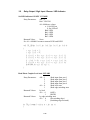
1E
Change the Keyboard map
Entry Parameters:
AH = 0x1E
BH = 1
3-44
; disable system keys
; enable system keys
DS:DX
keyboard map with 128 bytes
corresponded to numeric and alphabetic
ASCII code table; a NULL for
defining
unused key.
CX = 0x80
(table length for 128 bytes)
None
Returned Values:
=
void TD_key_map(unsigned char *str)
{
regs.h.ah=0x1E;
regs.h.bh=1;
regs.x.cx=0x80;
segregs.ds = FP_SEG(str);
regs.x.dx = FP_OFF(str);
int86x(0x21,®s,®s,&segregs);
}
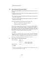
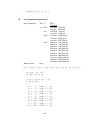
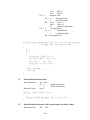
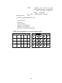
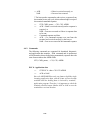
ASCII code corresponded to scan code in Numeric mode
ASCII code [Scan code]
Numeric keyboard layout
F1
F5
1
2
3
??
*
F2
??
??
F4
8A
[1B]
31
[13]
32
[0B]
33
[03]
F6
4
5
6
87
[22]
8B
[1A]
34
[12]
35
[0A]
36
[02]
F7
7
8
9
88
[21]
8C
[19]
37
[11]
38
[09]
39
[01]
[C]
0
[E]
89
[20]
1F
[18]
08
[10]
30
[08]
0D
[00]
?
F3
86
[23]
?
SHIFT
??
Figure 3-1 ASCII code vs. scan code cross reference table (numeric mode)
3-45
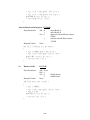
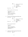
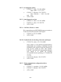
ASCII code corresponded to scan code in Alphabetic mode
Alphabetic mode keyboard layout
ASCII code, ASCII code, ASCII code
[Scan code, Scan code, Scan code]
F1
??
F2
??
F5
*
F6
?
QZ.
ABC
DEF
86
[23]
8A
[1B]
51,5A,2E
[24,25,26]
41,42,43
[27,28,29]
44,45,46
[2A,2B,2C]
GHI
JKL
MNO
87
[22]
8B
[1A]
4A,4B,4C
[30,31,32]
4D,4E,4F
[33,34,35]
F3
??
F4
??
F7
?
SHIF
T
PRS
TUV
WXY
88
[21]
8C
[19]
47,48,49
[2D,2E,2F
]
50,52,53
[36,37,38]
54,55,56
[39,3A,3B]
57,58,59
[3C,3D,3E]
[C]
-SP+
[E]
89
[20]
1F
[18]
08
[10]
2D,20,2B
[1D,1E,1F
]
0D
[00]
Figure 3-2 ASCII code vs. scan code cross reference table (alphabetic-mode)
3.8.
DOS Manager
The following MS/DOS function calls are emulated by MR350MKII. The calling
convention is identical to that of MS/DOS, i.e. INT 21H with function code in
registered AH. The parameter passing mechanism is also identical to the MS/DOS
convention. Unsupported DOS calls are returned with a completion status code
immediately. Please refer to MS/DOS Technical Reference Manual for further
details.
Standard Input/Output
01
Read stdin (wait if no key) and write it to stdout
No check on control keys (ESC)
Entry Parameters:
AH = 01
Returned Values:
AL = 8-bit data
unsigned char TS_stdin()
{
regs.h.ah= 1;
int86(0x21,®s,®s);
return(regs.h.al);
}
02
Write stdout
Entry Parameters:
AH = 02
3-46
Returned Values:
DL = 8-bit data
None
void TS_stdout(unsigned char ch)
{
regs.h.ah= 2;
regs.h.dl= ch;
int86(0x21,®s,®s);
return;
}
03
Read stdaux (COM2 RS-232 port)
No check on control keys (ESC)
Entry Parameters:
AH = 03
Returned Values:
AL = 8-bit data
unsigned char TS_stdaux_in()
{
regs.h.ah= 3;
int86(0x21,®s,®s);
return(regs.h.al);
}
04
Write stdaux (COM2 RS-232 port)
Entry Parameters:
Returned Values:
AH = 04
DL = 8-bit data
None
void TS_stdaux_out(unsigned char ch)
{
regs.h.ah= 4;
regs.h.dl= ch;
int86(0x21,®s,®s);
return;
}
06
Read / Write stdin or return 0 if none is ready
Entry Parameters:
Returned Values:
AH = 06
DL = 0~0xFE ; Write this character to stdout
FF
; Read stdin
For Write stdin : none
For Read stdin
if char ready, Zero = clear
AL = 8-bit data
3-47
if char not ready, Zero = set
unsigned char TS_stdin_out(unsigned char ch)
{
regs.h.ah= 6;
regs.h.dl= ch;
int86(0x21,®s,®s);
if (ch == 0xFF)
{
if ((regs.x.cflag & 0x40) == 0) return(regs.h.al);
else return(0);
}
return(0);
}
07
Read stdin (wait if no key)
No check on control keys (ESC)
Entry Parameters:
AH = 07
Returned Values:
AL = 8-bit data
unsigned char TS_stdin_noecho()
{
regs.h.ah= 7;
int86(0x21,®s,®s);
return(regs.h.al);
}
08
Read stdin (wait if no key)
No check on control keys (ESC)
Entry Parameters:
AH = 08
Returned Values:
AL = 8-bit data
unsigned char TS_stdin_wait()
{
regs.h.ah= 8;
int86(0x21,®s,®s);
return(regs.h.al);
}
09
Write character string to stdout
Entry Parameters:
Returned Values:
AH = 09
DS:DX = segment:offset of string
None
3-48
void TS_stdout_string(unsigned char *str)
{
segregs.ds = FP_SEG(str);
regs.x.dx = FP_OFF(str);
regs.h.ah= 9;
int86x(0x21,®s,®s,&segregs);
return;
}
0A
Keyboard buffer input
Entry Parameters:
AH = 0A
DS:DX = pointer to input buffer area
Returned Values:
Buffer filled with last character by a CR
void TS_stdin_string(unsigned char *str)
{
segregs.ds = FP_SEG(str);
regs.x.dx = FP_OFF(str);
regs.h.ah= 0x0a;
int86x(0x21,®s,®s,&segregs);
return;
}
0B
Keyhit check
Entry Parameters:
Returned Values:
AH = 0B
AL = 00 if char not ready
AL = FF if char ready
unsigned char TS_kbhit()
{
regs.h.ah= 0x0b;
int86(0x21,®s,®s);
return(regs.h.al);
}
Date/Time
The four function calls below are used to set/retrieve the system time and data by
directly accessing the real-time-clock chip.
2A
Get System date
Entry Parameters:
Returned Values:
AH = 2A
AL = Week
3-49
CX = year (1980..2099)
DH = month (1..12)
DL = day (1..31)
void TS_get_date(int *year,int *month,int *day,int *week)
{
TD_int_dos1(0x2a,0,0,0);
*year = regs.x.cx;
*month = regs.h.dh;
*day = regs.h.dl;
*week = regs.h.al;
}
2B
Set System date
Entry Parameters:
Returned Values:
AH = 2B
CX = year (1980..2099)
DH = month (1..12)
DL = day (1..31)
AL = 0
int TS_set_date(int year,int month,int day)
{
regs.h.ah = 0x2b;
regs.x.cx = year;
regs.h.dh = month;
regs.h.dl = day;
int86(0x21,®s,®s);
return(regs.h.al);
}
2C
Get System clock
Entry Parameters:
Returned Values:
AH = 2C
CH = hour (0..23)
CL = min (0..59)
DH = sec (0..59)
DL = 0
void TS_get_time(int *hour,int *minute,int *second,int *hund_sec)
{
TD_int_dos1(0x2c,0,0,0);
*hour = regs.h.ch;
*minute = regs.h.cl;
*second = regs.h.dh;
*hund_sec = regs.h.dl;
}
3-50
2D
Set System clock
Entry Parameters:
Returned Values:
AH = 2D
CH = hour (0..23)
CL = min (0..59)
DH = sec (0..59)
AL = 0
int TS_set_time(int hour,int minute,int second,int hund_sec)
{
regs.h.ch = hour;
regs.h.cl = minute;
regs.h.dh = second;
regs.h.dl = hund_sec;
regs.h.ah = 0x2d;
int86(0x21,®s,®s);
return(regs.h.al);
}
3.9.
File Manager
When the file is downloaded or uploaded, the working file can not be opened
by the application command. As the same result, when the file is opened by
application, the host computer can not download or upload with the same
file. This limitation is used to protect the file pointer from re-writing and
corrupt the file system.
3C
Create or truncate file
When a file is created, the file manager searches the file table for a file name
matched. If it is found, the corresponding file handle is returned, and the file
pointer is reset to the beginning of the file. The actual file size is reset to
zero. If the file does not exist in the file table, a file entry is allocated, and
memory is assigned.
Entry Parameters:
Returned Values:
AH = 3C
DS:DX = segment:offset of ASCIIZ file name
if successful : Carry = clear, AX = handle
if fail : Carry = set, AX = 3
int TS_create_file(char *fn)
{
segregs.ds = FP_SEG(fn);
regs.x.dx = FP_OFF(fn);
regs.h.ah=0x3C;
int86x(0x21,®s,®s,&segregs);
3-51
if ((regs.x.cflag & 0x01) == 1) return(-1);
else return(regs.x.ax);
}
3D
Open file
The file must exist in the file table. This function returns the file handle.
Entry Parameters:
Returned Values:
AH = 3D
AL = 0
; Read only
1
; Write only
2
; Both Read and Write
DS:DX = segment:offset of ASCIIZ file name
if successful : Carry = clear, AX = handle
if fail : Carry = set, AX = 2
When a file is opened, the file manager searches the file table for a file name
match. If a match is found, the corresponding file handle is returned. The
current pointer is reset to the beginning of the file, i.e. the current offset field
is set to zero.
int TS_open_file(char *fn,int mode)
{
regs.h.al=(unsigned char)mode;
segregs.ds = FP_SEG(fn);
regs.x.dx = FP_OFF(fn);
regs.h.ah=0x3D;
int86x(0x21,®s,®s,&segregs);
if ((regs.x.cflag & 0x01) == 1) return(-1);
else return(regs.x.ax);
}
3E
Close file
Entry Parameters:
Returned Values:
AH = 3E
BX = file handle
Carry = clear
= set
void TS_close_file(int hdl)
{
regs.h.ah= 0x3e;
regs.x.bx= hdl;
int86(0x21,®s,®s);
}
3-52
; OK
; Failed
3F
Read file
Copy (CX) bytes from current address to DS:DX.
Advance the current address (CX) number of bytes.
Entry Parameters:
Returned Values:
AH = 3F
BX = file handle
CX = number of bytes to read
DS:DX = segment:offset of buffer area
if successful: Carry = clear,
AX = number of bytes read, 0 if EOF
if fail:
Carry = set, AX = 6
int TS_read_file(int hdl,int cnt,char *str)
{
segregs.ds = FP_SEG(str);
regs.x.dx = FP_OFF(str);
regs.h.ah=0x3f;
regs.x.cx=cnt;
regs.x.bx=hdl;
int86x(0x21,®s,®s,&segregs);
if ((regs.x.cflag & 0x01) == 0) return(regs.x.ax);
else return(-1);
}
40
Write file
Copy (CX) bytes from DS:DX to file (BX). Update BX current address and
ending address. If CX is assigned with 0 (zero), the system will truncate the
file from the current file pointer position. This function can be used by MSC
function call chsize().
Entry Parameters:
Returned Values:
AH = 40
BX = file handle
CX = number of bytes to write or 0
DS:DX = segment:offset of buffer area
if successful: Carry = clear,
AX = number of bytes read, 0 if full
if fail: Carry = set, AX = 6
int TS_write_file(int hdl,int cnt,char *str)
{
segregs.ds = FP_SEG(str);
regs.x.dx = FP_OFF(str);
regs.h.ah=0x40;
regs.x.bx=hdl;
regs.x.cx=cnt;
int86x(0x21,®s,®s,&segregs);
3-53
if ((regs.x.cflag & 0x01) == 0) return(regs.x.ax);
else return(-1);
}
41
Delete file
Entry Parameters:
Returned Values:
AH = 41
DS:DX = segment:offset of ASCIIZ file name
if successful : Carry = clear,
if fail : Carry = set, AX = 2
int TS_delete_file(char *fn)
{
segregs.ds = FP_SEG(fn);
regs.x.dx = FP_OFF(fn);
regs.h.ah=0x41;
int86x(0x21,®s,®s,&segregs);
if ((regs.x.cflag & 0x01) == 0) return(1);
else return(-1);
}
42
Move file pointer
Entry Parameters:
Returned Values:
AH = 42
AL = 0 offset from beginning
1 offset from current
2 offset from end
BX = file handle
CX = most significant half of offset
DX = least significant half of offset
if successful: Carry = clear,
AX = least significant half of new current
DX = most significant half of new current
if fail: Carry = set, AX = 6
struct LONG_INT {
long ll;
};
struct LONG_INT1 {
unsigned int ii1, ii2;
};
union LONG_III {
struct LONG_INT l;
struct LONG_INT1 i;
};
3-54
long TS_seek_file(int hdl,int type,long loc)
{
union LONG_III aa;
regs.h.ah=0x42;
regs.h.al=(unsigned char)type;
regs.x.bx=hdl;
aa.l.ll = loc;
regs.x.cx=aa.i.ii2;
regs.x.dx=aa.i.ii1;
int86(0x21,®s,®s);
aa.i.ii2=regs.x.dx;
aa.i.ii1=regs.x.ax;
if ((regs.x.cflag & 0x01) == 0) return(aa.l.ll);
else return(-1L);
}
43
Get file attribute
Entry Parameters:
Returned Values:
AH = 43
AL = 0
DS:DX = segment:offset of ASCIIZ file name
if file found: Carry = Clear, CX = 0
if file not found: Carry = set, AX = 2
int TS_check_file_exit(char *str)
{
regs.h.ah=0x43;
regs.h.al=0;
segregs.ds = FP_SEG(str);
regs.x.dx = FP_OFF(str);
int86x(0x21,®s,®s,&segregs);
if ((regs.x.cflag & 0x01) == 0) return(1);
else return(0);
}
56
Rename a file
Entry Parameters:
Returned Values:
AH = 56
DS:DX = pointer to ASCII filename to be renamed
ES:DI = pointer to new ASCII filename
AH = 0 and clear Carry flag ;if success
1 and set Carry flag ;if not success
int TS_rename_file(char *inf,char far *outf)
{
3-55
segregs.ds = FP_SEG(inf);
regs.x.dx = FP_OFF(inf);
segregs.es = FP_SEG(outf);
regs.x.di = FP_OFF(outf);
regs.h.ah=0x56;
int86x(0x21,®s,®s,&segregs);
if ((regs.x.cflag & 0x01) == 0) return(regs.x.ax);
else return(-1);
}
Memory Access
48
Allocate specified number of paragraphs memory
Entry Parameters:
Returned Values:
49
Free allocated memory
Entry Parameters:
Returned Values:
4A
AH = 48
BX = number of segment
AX = seg addr of block allocated Error
code, if carry flag set
BX = largest available block (on failure)
AH = 49
ES = seg of block to free
AX = error code, if carry flag is set
BX = largest available block (on failure)
Modify allocated block
Entry Parameters:
Returned Values:
ES = seg of the block to modify
BX = The new number of segs wanted
AX = error code, if carry flag is set
BX = largest available block (on failure),
if carry flag is set
3-56
This page is blank.
3-57
Chapter 4. Host ESC Commands
4.
Host ESC Commands
There are three classes of host communication activities:
(1)
Host Sends Control/Configuration Commands to the MR350MKII
Almost all MR350MKII configurations and operations may be controlled by
the host system via control commands. Configuration commands are used to
set up system tables such as the communication control table. Control
commands are used to abort MR350MKII operations, reset the
MR350MKII, instruct the MR350MKII to execute an application program,
or other functions related to operations.
Configuration commands are normally issued by the host system during the
initialization process. Control commands, however, may be issued at any
time during normal operation or during a recovery action.
(2)
Host Requests Data from the MR350MKII
Two kinds of data are usually requested by the host system: MR350MKII
system data and application data. Application data is the information which is
generated from application program, system data is the information which is
pertinent only to MR350MKII executives, e.g. file names, system
parameters, etc. The MR350MKII transmits data depending on the protocol
used.
(3)
File Transfers Between the Host and the MR350MKII
Executable program file and data files are downloaded to the MR350MKII
from the host or uploaded to the host from the MR350MKII. File transfers
may use a special file transfer protocol to move data in a point-to-point or
multi-point connection.
In the following sections we will first discuss the host communication commands and
briefly describe their functions. Then we will examine detailed protocol of each
function.
4.1.
General Control Commands
1.
Hard Reset ( ESC H )
A hard reset command clears all the MR350MKII RAM memory content. It
performs tests on all major hardware devices. Programs or data that have
previously accumulated in the MR350MKII or previously been downloaded
by the host will be purged from the memory. Default system parameters are
4-58
restored from the Flash ROM.The hard reset command will not purge the
program files that stored on Flash ROM
The hard reset command does not have any parameter or value. The
equivalent keypad invoking sequence is entering the supervisor mode and
selecting an initialization command.
2.
Abort ( ESC A )
Abort is the "soft reset" command. The MR350MKII terminates its
execution and returns to ready mode. Programs and data that have been
stored in the MR350MKII RAM space are preserved. The system
parameters remain unchanged. The abort command does not have any
parameter or value. The equivalent keypad invoking sequence is pressing the
[SHIFT] and [F5/*] keys at the same time.
3.
Execute ( ESC X filename )
The host system may instruct the MR350MKII to execute a program which
is resided in the RAM or Flash ROM of MR350MKII. The host issues this
command with the executable program name as its parameter. The
MR350MKII acknowledges with an ACK response if the program exists and
starts execution.
The Execute command has one parameter, the file name. The Execute
command can also be invoked via the MR350MKII workstation menu.
Execute Flash ROM program ( ESC X/ROM filename )
The host system may instruct the MR350MKII to execute a program which
is resided in the Flash ROM of MR350MKII.
4.
Directory ( ESC D )
The directory command instructs the MR350MKII to return a list of
available files in the RAM of the MR350MKII. The directory command can
also be invoked via the MR350MKII workstation menu. When invoked from
the keypad the directory is listed on the LCD display.
Directory Flash ROM ( ESC D/ROM )
The directory command instructs the MR350MKII to return a list of
available programs in the Flash ROM of the MR350MKII.
5.
Erase ( ESC E filename )
The erase command deletes a file from the MR350MKII RAM. An ACK
response will be given if the file existed and was deleted, otherwise an NAK
response is generated by the MR350MKII. The erase command has one
parameter, the file name. The erase command can also be invoked via the
MR350MKII workstation menu.
4-59
6.
Autoboot ( ESC O program name )
This command defines an autoboot program name in the MR350MKII. The
autoboot program will be executed automatically each time the power is
turned OFF and ON.
7.
Password ( ESC P password )
To create or edit a supervisor password.
8.
Get RAM size (ESC G)
Get the MR350MKII total RAM size, program execution memory, and free
memory which available for RAM disc.
Get Flash ROM size (ESC G/ROM)
Get the MR350MKII total Flash ROM size and free memory which available
for RAM disc.
9.
Get filename of current executing program (ESC I filename)
While the <ESC I> command is received by MR350MKII, the system will
response the current executing program name or no program is running.
10.
Check file existed and files size(ESC J filename)
Check if the file is existed on MR350MKII or not. If file is exist, it will return
its size
11.
Set keyboard locking (ESC K state)
Set the MR350MKII ? keyboard locking state. There are three states
allowed to be assigned: UNLOCK, LOCK, or PARTIAL LOCK.
12.
Change terminal address ID (ESC 5 ID)
Assign a new terminal address ID to the terminal. Once the terminal address
ID is changed, it will take effect immediately without having to reset the
terminal.
13.
Disable UPS battery (ESC F)
In general, UPS battery can supply power to MR350MKII when disconnect
power adapter or power failure. User can use this command to disable UPS
battery after power failure.
14.
Loopback test (ESC 9)
The loopback test is used for testing the line communication. The testing
program run on host sends this command with test data to terminal and
terminal echoes back the data to be verified by the program.
4-60
15.
Buzzer Volume (ESC N)
This command can remote changing MR350MKII's buzzer sound.
16.
Supervisor password (ESC P)
This command can remote changing MR350MKII's buzzer sound.
17.
Get terminal ID (ESC R)
This commcand can get terminal ID. The default terminal ID is "MR350"
18.
Get terminal ID and version no (ESC v)
This commcand can get terminal ID and version no. The default terminal ID
is "MR350 V4.xx".
4.2.
Configuration Commands
Configuration commands from the host always follow the standard host command
sequence: ESC, cmd, table. The cmd field actually specifies the object to be
configured. The table field contains the data organized in a pre-defined format.
1.
Terminal Configuration ( ESC T )
The terminal configuration command has the following format:
ESC T termtable
This command takes the data structure "termtable" from the host and writes
it to the MR350MKII internal terminal control table. The structure within
"termtable" must conform to the TERM_CONFIG typedef (see section 2.5
on page 2-17) specified in the previous section.
The new terminal control table takes effect immediately after the ESC T
command has been successfully received.
2.
Communication Configuration ( ESC C )
The communication configuration command has the following format:
ESC C comtable
This command takes the data structure "comtable" from the host and writes
it to one of the two MR350MKII internal communication control tables. The
structure within "comtable" must conform to the COM_CONFIG typedef
(see section 2.4 on page 2-16) specified in the previous section.
4-61
The new communication control table takes effect immediately after the ESC
C command has been successfully received. The MR350MKII will
reinitialize the corresponding communication port with its new parameters.
For example, if ESC C instructs the RS-232 port to change the baud rate
from 9600 to 1200 the MR350MKII will switch to 1200 right after the ESC
C command has been received. The next host communication will use 1200
baud.
3.
Device Configuration ( ESC V )
The device configuration command has the following format:
ESC V devtable
This command takes the data structure "devtable" from the host and writes it
to the MR350MKII internal device control table. The structure of "devtable"
must conform to the DEV_CONFIG typedef (see section 0 on page 2-14)
specified in the previous section.
The new device control table takes effect immediately after the ESC V
command has been successfully received.
4.
Barcode symbology Configuration ( ESC B )
The barcode symbology configuration command has the following format:
ESC V bartable
This command takes the data structure "bartable" from the host and writes it
to the MR350MKII internal barcode symbology control table. The structure
of "bartable" must conform to the BAR_CONFIG typedef (see section 0 on
page 2-13) specified in the previous section.
The new device control table takes effect immediately after the ESC V
command has been successfully received.
5.
Date/Time Configuration ( ESC M )
The date/time configuration command has the following format:
ESC M datetime
This command allows the host system to initialize the MR350MKII real time
clock function. The parameter datetime is an ASCII character string with the
following interpretations: yyyymmddhhmmss.
The first four characters represent the year. The next two characters
represent the month, where January is 01. The fields after the month field
represent the day of the month, hour (24 hour format), minute, and second,
respectively.
4-62
For example, command ESC M 199009262345 will initialize the
MR350MKII clock to September 26, 1990. The time is 11:45 PM. The
MR350MKII reconfigures the real time clock chip as soon as the ESC M
command has been successfully received.
4.3.
File Transfer Commands
1.
Download ( ESC L filename )
The download command is used to transfer a binary executable program or
data file from the host system to the MR350MKII. When the MR350MKII
receives the download command it sends an ACK response back to the host
and immediately puts itself into a file receiving state. The file receiving state
is determined by a preassigned host protocol Kermit. The host system may
start transmission of the file as soon as the ACK response has arrived.
The download command has one parameter, the file name. Download can
also be invoked via the MR350MKII workstation menu.
The upload command performs the opposite function of the download
command. It is normally used to transfer a data file from the MR350MKII to
the host system. This is the typical means of retrieving collected data in
workstation mode.
2.
Upload ( ESC U filename )
When the MR350MKII receives an upload command it puts itself in file
transmission state and starts sending the designated data file. The file transfer
protocol is determined by a preassigned host protocol Kermit. The host
system waits for the arrival of the data file after it sends out the upload
command.
The upload command has one parameter, the file name. The upload
command can also be invoked via the MR350MKII workstation menu.
4.4.
Multipoint Protocol
In Multipoint operation the MR350MKII uses an asynchronous serial
multi-drop protocol for communication with the host computer. Note that to
make this protocol operable an RS-232 to RS-485 converter is needed
between the host and the MR350MKII. The terminal protocol consists of
commands and responses of the following format:
Symbol
Description
=>
Transmission from host to terminal
<=
Transmission from terminal to host
4-63
ADDR Terminal address (A-Y,0-6) + 80H
CMD
Network command to terminal, 2 bytes, A-F,0-9
CS1
Checksum, first byte
CS2
Checksum, second byte
The checksum is calculated by adding each byte of the transmission, ADDR,
and length of data block (excluding STX and ETX). CS1 is high nibble (4
bits) +40H and CS2 is low nibble +40H.
Example: Command to load the file named A.EXE
STX ESC L A . E X E CS1 CS2 ADDR
Data block
= ESC L A . E X E (excluding STX)
Length of data block = 7
CS
= ESC + L + A + . + E + X + E + ADDR + 7
CS1
= high nibble of CS + 40H
CS2
= low nibble of CS + 40H
The ASCII data characters and their values are as follows:
STX
0x02
ETX
0x03
ACK 0x06
NAK 0x15
DC1
0x11
ESC
0x1B
EOT
0x04
The maximum frame size including protocol control characters is 128 bytes.
Transparent transmission of protocol control characters STX and ETX is
achieved by preceding them with a '\' (backslash) character. Transparent
transmission of the '\' character is achieved by sending two '\' characters
consecutively.
Rule of data convention during data transmission:
1)
One-byte data converted to two-byte data
4-64
\
convert to
\\
00 hex -- 1F hex
convert to
\ 80 hex -- \ 9F hex
A0 hex -- FF hex
convert to
\ 20 hex -- \ 7F hex
(excluding DC hex)
2)
one-byte data transmitted as original data without converting
unchanged
other codes
Host Transmissions
Transmission
Format
Poll
STX, ADDR
Host Data
STX, CMD, data, CS1, CS2, ADDR
Acknowledgment
ACK
Negative ACK
NAK
Terminal Transmissions
Transmission
Format
Terminal Data
STX, data, CS1, CS2, ETX
Acknowledgment
ACK
Negative ACK
NAK
4.4.1. Protocol Operation
The terminal protocol operates as a multi-point stop and wait
protocol. A station sends only one frame and then stops and waits for
a response.
The following scenarios typify link transmissions (Poll):
* Terminal has no data for the host:
=> STX ADDR
<= EOT - if no data is ready for transmission
* Terminal has data for the host:
=> STX ADDR
<= STX <data> CS1 CS2 ETX - if data is ready
4-65
=> ACK
NAK
- if data is received correctly, or
- if an error has occurred
* The host sends a command to and receives a response from
the terminal in one poll cycle; it then acknowledges receipt of
the terminal command response:
=>
<=
<=
=>
STX, CMD, parms, ... CS1, CS2, ADDR
ACK - if data is received correctly and no response is
required, or
NAK - if an error occurred or if there is response data
to be sent.
Command response and data:
ACK - if a command response was sent from the
terminal and received correctly by the host, or
NAK - if an error occurred in the command response
4.4.2. Commands
The following commands are supported for download, diagnostic,
and application data transfers. Each command and its parameters
will be framed as shown before being transmitted; responses have the
same format without the ADDR fields.
STX, CMD, parms, ... CS1, CS2, ADDR
ESC 0 - Application data
=>
<=
STX ESC 0 <data> CS1 CS2 ADDR
ACK or NAK
Since the MR350MKII has only one frame to hold the single
incoming application data, and the frame will not become
available until the holding data is retrieved by terminal?
application program. Therefore, it is important to check the
terminal echo back status whether ACK or NAK to sure the
terminal has received the data.
4-66
ESC 5 - Set multipoint address
=>
STX ESC '5' <addr> CS1 CS2 ADDR
where <addr> = 'A'~'Y','0'~'6'
<=
STX ESC '5' <Retcode> CS1 CS2 ETX
where <Retcode>= 0x00 if set OK
0x01 error
=>
ACK or NAK
ESC 9 - Send diagnostic test data
=>
STX ESC '9' <data> CS1 CS2 ADDR
<=
STX ESC '9' <data> CS1 CS2 ETX
=>
ACK or NAK
ESC A - Soft Reset, Restart, or Abort
This command stops any MR350MKII program execution as
if control-exit has been pressed on the keypad.
=>
<=
STX ESC A CS1 CS2 ADDR
ACK or NAK
ESC B - Enable/disable the decoding of barcode symbologies:
=>
STX ESC B <abcde> CS1 CS2 ADDR
where <abcde> is a five-character-positioned data to
enable/disable the decoding of individual barcode
symbology by the sequence of the first character for
Code 39, the second for I2of5, then Codabar,
EAN/UPC, and Code 128. Each positioned character
with content of 'N' enables the decoding
corresponded barcode symbology or 'F' disables the
decoding.
<=
=>
STX ESC B <Retcode> CS1 CS2 ETX
ACK or NAK
ESC C - Write communication configuration table to
MR350MKII
=>
<=
=>
STX ESC C <comtable> CS1 CS2 ADDR
STX ESC C <Retcode> CS1 CS2 ETX
ACK or NAK
4-67
ESC D - Read directory of RAM disk to host
=>
<=
=>
STX ESC D CS1 CS2 ADDR
STX ESC D <directory data> CS1 CS2 ETX (or
NAK)
ACK or NAK
ESC D/ROM - Read directory of Flash ROM to host
=>
<=
=>
STX ESC D/ROM CS1 CS2 ADDR
STX ESC D/ROM <directory data> CS1 CS2 ETX
(or NAK)
ACK or NAK
ESC E - Erase a file from the MR350MKII directory
=>
<=
=>
STX ESC E <filename> CS1 CS2 ADDR
STX ESC E <RetCode> CS1 CS2 ETX
where <RetCode>:
00
if successfully erased
01
file does not exist
ACK or NAK
ESC F - Disable UPS battery to supply power
This command is used to stop UPS battery to continue to
supply power to terminal. By using this command you can
prevent exhausting UPS battery when the power source is
switched off for some time.
=>
<=
STX ESC F CS1 CS2 ADDR
ACK or NAK
ESC G - Get MR350MKII's RAM size
=> STX ESC G CS1 CS2 ADDR
<= STX ESC G <xxx> <yyy> <zzz> CS1 CS2 ETX
where <xxx>= number of Kbytes of total memory
<yyy>= number of Kbytes of Exec memory
<zzz>= number of Kbytes of Free memory
=> ACK or NAK
4-68
ESC G/ROM - Get MR350MKII's Flash ROM size
=> STX ESC G/ROM CS1 CS2 ADDR
<= STX ESC G/ROM <xxx> <zzz> CS1 CS2 ETX
where <xxx>= number of Kbytes of total memory
<zzz>= number of Kbytes of Free memory
=> ACK or NAK
ESC H - Hard Reset and initiate power on test
This command resets the MR350MKII terminal, and running
applications are halted. Power-on test routines are run and, if
completion is normal, the MR350MKII is ready for the next
command.
=>
<=
STX ESC H CS1 CS2 ADDR
ACK or NAK
ESC I - Get filename of current executing program
=>
<=
=>
STX ESC I CS1 CS2 ADDR
STX ESC I <filename> CS1 CS2 ETX
if a program with filename is running in
terminal
STX ESC I <01> CS1 CS2 ETX
if no program is running
ACK or NAK
ESC J - Check if file existed or not
=> STX ESC J <filename> CS1 CS2 ADDR
<= STX ESC J <Retcode> CS1 CS2 ETX
where Retcode = 00 means file exist
= 01 means file not exist
=> ACK or NAK
4-69
ESC K - Set keyboard locking
=> STX ESC K <state> CS1 CS2 ADDR
where state = '0' set keyboard LOCK
= '1' set keyboard UNLOCK
= '2' set keyboard Partial LOCK
<= STX ESC K <Retcode> CS1 CS2 ETX
where Retcode = 00 if successful
= 01 if not successful
=> ACK or NAK
ESC L - Transfer file to MR350MKII
=>
<=
...
=>
<=
STX ESC L <filename> CS1 CS2 ADDR
ACK or NAK
.... loop on next two steps to transfer file until done
=>
STX ESC 'Y' <data> CS1 CS2 ADDR
<=
ACK or NAK
STX ESC Z CS1 CS2 ADDR (end of data sending)
ACK or NAK
ESC M - Write date and time to MR350MKII
=>
<=
=>
STX ESC M <datetime> CS1 CS2 ADDR
where <datetime>
yyyymmddhhmmss in ASCII string
STX ESC M <Retcode> CS1 CS2 ETX
ACK or NAK
ESC N - Set Buzzer Volume
? ? STX ESC ‘N’<n> CS1 CS2 ADDR
Where <n> = ‘0’low volume
‘5’medium volume
‘9’high volume
? ACK or NAK
ESC O - Set auto-execution program
=> STX ESC O <program name> CS1 CS2 ADDR
<= STX ESC O <Retcode> CS1 CS2 ETX
where Retcode = 00 if successful
= 01 if not successful
=> ACK or NAK
4-70
ESC O/ROM - Set auto-execution program on ROM
=> STX ESC O <program name>/ROM CS1 CS2 ADDR
<= STX ESC O <Retcode>/ROM CS1 CS2 ETX
where Retcode = 00 if successful
= 01 if not successful
=> ACK or NAK
ESC P - Set supervisor password (maxi. 8 characters)
=> STX ESC P <password> CS1 CS2 ADDR
<= ACK or NAK
ESC R - Terminal ID
=> STX ESC R CS1 CS2 ADDR
<= STX ESC T <terminal_id> CS1 CS2 ETX
=> ACK or NAK
ESC T - Write terminal configuration table to MR350MKII
=>
<=
=>
STX ESC T <termtable> CS1 CS2 ADDR
STX ESC T <Retcode> CS1 CS2 ETX
where Retcode= 00 means successful
= 01 means unauthorized command
ACK or NAK
ESC U - Transfer file from MR350MKII
=>
<=
<=
=>
STX ESC U <filename> CS1 CS2 ADDR
ACK or NAK or EOT (when file not found)
.... loop on next two steps to transfer file until done
=>
STX ESC 'Y' CS1 CS2 ADDR
<=
STX ESC 'Y' <data> CS1 CS2 ETX
<=
ACK or NAK
STX ESC Z CS1 CS2 ETX (end of file transfer)
ACK or NAK
ESC V - Write device configuration table to MR350MKII
=>
<=
STX ESC V <devtable> CS1 CS2 ADDR
STX ESC V <Retcode> CS1 CS2 ETX
4-71
=>
ACK or NAK
ESC v - Get Terminal ID and version no
=>
<=
=>
STX ESC V <devtable> CS1 CS2 ADDR
STX ESC V <terminal_id and ver> CS1 CS2 ETX
ACK or NAK
ESC X - Start program execution
=>
<=
=>
STX ESC X <filename> CS1 CS2 ADDR
STX ESC X <RetCode> CS1 CS2 ETX
where <RetCode>:
00
if successfully started
01
file does not exist
ACK or NAK
Where the <filename> should contain the name of file only
but without file extension name “.EXE”.
For example: A executable program named ? RV30.EXE”
Command : STX ESC X DRV30 CS1 CS2 ADDR
ESC X - Start program execution on ROM
=>
<=
=>
STX ESC X <filename>/ROM CS1 CS2 ADDR
STX ESC X <RetCode>/ROM CS1 CS2 ETX
where <RetCode>:
00
if successfully started
01
file does not exist
ACK or NAK
Where the <filename> should contain the name of file only
but without file extension name “.EXE”.
For example: A executable program named ? RV30.EXE”
Command : STX ESC X DRV30 CS1 CS2 ADDR
4.5.
ESC Commands Added for MV1100 Fingerprint Module .
ESC $D
Get Template List
A list of all stored templates on the MV1100 is updated to the MR350
MKII reserved file $FP.LST. The items in $FP.LST have the format
4-72
of $Txxxxxxxxxx.yyy, where xxxxxxxxx is the template ID and yyy is
the template index.
==> STX ESC $D CS1 CS2 ADDR
<== STX ESC $D RESULT CS1 CS2 ETX
or
<== NAK
RESULT
=
‘0’
;success
=
‘1’
;fail
=
‘2’
;busy
=
‘3’
;timeout
NAK means command format error or checksum error.
For the host to get the MV1100 template list, it should issue ESC $D
command first and then issue ESC U command to upload file $FP.LST
if ESC $D command is successful.
4-73
ESC $E Erase Template
The command erases the specified template on MV1100.
==> STX ESC $E xxxxxxxxxx.yyy CS1 CS2 ADDR
<== STX ESC $E RESULT CS1 CS2 ETX
or
<== NAK
xxxxxxxxxx
;template ID
( ‘1’ -- ‘4294967294’)
yyy
RESULT
=
;template index ( ‘0‘-- ‘255’)
‘0’
;success
=
‘1’
;fail
=
‘2’
;busy
=
‘3’
;timeout
NAK means command format error or checksum error.
ESC $F Enroll and Store Template on MR350 MKII
The command enrolls and stores the template with the specified ID
to the MR350 MKII reserved file $FP.UPL .
==> STX ESC $F xxxxxxxxxx CS1 CS2 ADDR
<== STX ESC $F RESULT < ,QUALITY, CONTENT >
CS1 CS2 ETX
or
<== NAK
xxxxxxxxxx
RESULT
=
;template ID
‘0’
;success
( ‘1’-- ‘4294967294’)
=
‘1’
;fail
=
‘2’
;busy
=
‘3’
;timeout
If RESULT = ‘0’, MR350MKII will response with
QUALITY and CONTENT fields:
QUALITY is an integer that has a range of ‘000’–
‘100’
CONTENT is an integer that has a range of ‘000’–
‘100’
NAK means command format error or checksum error.
For the host to get the template, it should issue ESC $F command
first and then issue ESC U command to upload file $FP.UPL if ESC
$F command is successful.
4-74
ESC $G Enroll and Store Template on MV1100 ()
The command enrolls and stores the template with the specified ID
on MV1100.
==> STX ESC $G xxxxxxxxxx CS1 CS2 ADDR
<== STX ESC $G RESULT < ,QUALITY, CONTENT >
CS1 CS2 ETX
or
<== NAK
xxxxxxxxxx
RESULT
;template ID
( ‘1’-- ‘4294967294’)
‘0’
;success
=
=
‘1’
;fail
=
‘2’
;busy
=
‘3’
;timeout
If RESULT = ‘0’, MR350MKII will response with
QUALITY and CONTENT fields:
QUALITY is an integer that has a range of
‘000’– ‘100’
CONTENT is an integer that has a range of
‘000’– ‘100’
NAK means command format error or checksum error.
ESC $H Verify Template
The command requests to verify the fingerprint against the template
saved in the MR350 MKII reserved file $FP.DNL .
.
==> STX ESC $H CS1 CS2 ADDR
<== STX ESC $H RESULT < , INDEX , SCORE > CS1
CS2 ETX
or
<== NAK
RESULT
=
‘0’
;success
=
‘1’
;fail
=
‘2’
;busy
=
‘3’
;timeout
If RESULT = ‘0’, MR350MKII will response with
INDEX and SCORE fields:
INDEX is the index of the matched template that
has an range of ‘000’– ‘255’
4-75
SCORE is an integer that has a range of ‘000’–
‘100’
NAK means command format error or checksum error.
For the host to verify against the template saved on its disk, it should
issue ESC L command first to download the template to the MR350
MKII reserved file $FP.DNL and then issue ESC $H command to
verify the fingerprint if ESC L command is successful.
ESC $I Verify ID ()
The command requests to verify the fingerprint against the
template(s) with the specified ID stored on MV1100.
==> STX ESC $I xxxxxxxxxx CS1 CS2 ADDR
<== STX ESC $I RESULT < , INDEX , SCORE > CS1 CS2
ETX
or
<== NAK
xxxxxxxxxx
RESULT
;template ID
‘0’
;success
=
=
‘1’
;fail
=
‘2’
;busy
=
‘3’
;timeout
If RESULT = ‘0’, MR350MKII will response with
INDEX and SCORE fields:
INDEX is the index of the matched template that
has an range of ‘000’– ‘255’
SCORE is an integer that has a range of ‘000’–
‘100’
NAK means command format error or checksum error.
ESC $L Download Template
The command downloads the template from the MR350 reserved file
$FP.DNL to MV1100 and stores the template in MV1100 flash
memory .
==> STX ESC $L CS1 CS2 ADDR
<== STX ESC $L RESULT CS1 CS2 ETX
or
<== NAK
RESULT
=
‘0’
4-76
;success
=
‘1’
;fail
=
‘2’
;busy
=
‘3’
;timeout
NAK means command format error or checksum error.
For the host to download the template saved on its disk, it should
issue ESC L command first to download the template to the MR350
MKII reserved file $FP.DNL and then issue ESC $L command to
download it to MV1100 if ESC L command is successful.
ESC $S Set Globe Threshold ()
The command sets the globe verification value for MV1100 .
==> STX ESC $S THRESH CS2 ADDR
<== STX ESC $S RESULT CS1 CS2 ETX
or
<== NAK
THRESH
=
‘1’
,very high security
=
‘2’
;high security
=
‘3’
;medium security
=
‘4’
;low security
RESULT
=
=
‘5’
‘0’
;very low security
;success
=
‘1’
;fail
=
‘2’
;busy
=
‘3’
;timeout
NAK means command format error or checksum error.
ESC $S Get Globe Threshold ()
The command sets the globe verification value for MV1100 .
==> STX ESC $S CS2 ADDR
<== STX ESC $S RESULT < ,THRESH > CS1 CS2 ETX
or
<== NAK
RESULT
=
‘0’
;success
=
‘1’
;fail
=
‘2’
;busy
=
‘3’
;timeout
If RESULT = ‘0’, MR350MKII will response with
THRESH field:
4-77
THRESH =
‘1’
,very high security
=
‘2’
;high security
=
‘3’
;medium security
=
‘4’
;low security
=
‘5’
;very low security
NAK means command format error or checksum error.
ESC $U Upload Template ()
The command uploads the specified template from MV1100 flash
memory to the MR350 reserved file $FP.UPL .
==> STX ESC $U xxxxxxxxxx.yyy CS1 CS2 ADDR
<== STX ESC $U RESULT CS1 CS2 ETX
or
<== NAK
xxxxxxxxxx
;template ID
( ‘1’ -- ‘4294967294’)
yyy
RESULT
=
;template index ( ‘0‘-- ‘255’)
‘0’
;success
=
‘1’
;fail
=
‘2’
;busy
=
‘3’
;timeout
NAK means command format error or checksum error.
For the host to upload the specified template on MV1100, it should
issue ESC $U command first to upload the template to the MR350
MKII reserved file $FP.UPL and then issue ESC U command to
upload file $FP.UPL if ESC $U command is successful.
ESC $V Get Version
The command gets the software version information from MV1100.
==> STX ESC $V CS1 CS2 ADDR
<== STX ESC $V RESULT < , Kx.xxx Ay.yyyy > CS1
CS2 ETX
or <== NAK
RESULT
=
‘0’
;success
=
=
=
‘1’
‘2’
‘3’
;fail
;busy
;timeout
4-78
If RESULT = ‘0’, MR350MKII will response with the
version field:
Kx.xxxx Ay.yyyy where x.xxxx represents the
version of the kernal and y.yyyy represents the
version number of the algorithm.
NAK means command format error or checksum error.
4-79
Chapter 5. How to programning ?
5.
How to to
programming
There are two major parts for programming – 1. Programming MR350 MKII and 2.
Programming communication program between MR350 MKII and Host computer. The
following topic describe application and utility library that will help users to develop quickly
and efficiently for their applications.
5.1.
Programming MR350 MKII
MR350 MKII’s OS is an open architecture and it provides a MS-DOS compatible
platform, user can write a program run on MR350 MKII to fully control its
input/output facilities or have a complicate accumulation, data validation or table
look up features for your application program. So, users can use standard C, C++
or Assembly language development tools to develop their application. In Chapter
3, it describes detail DOS/BIOS call of MR350MKII, user can directly refer to this
chapter to implement application program. If user dosen’t familiar or skillful in
programming language. Unitech also a program generator tool – Job Generator
Pro (JobGen Pro). The MR350 MKII allows the user to write his application
program by the following programming tools.
? ? JobGen Pro, a DOS base program generator that requiring the minimum
programming skills. Please contact your local distributor or dealer for more
detailed information.
? ? Microsoft C version 5.x, 6.x, 7.x or 8.x for MSDOS application
? ? Microsoft Visual C/C++ V1.52 or below for MSDOS application
? ? Borland C/C++ or Turbo C/C++ for MSDOS application
? ? Macro Assembler for MSDOS application
5-80
5.1.1. Programming by JobGen PRO
The JOB GENerator PROfessional (JobGenPRO) is an MS-DOS based software
for developing applications for MR350MKII. With JobGenPRO, application
developers may create an application program easily by defining the transactions,
attributes of data fields and operation flow without writing program code. An
executable program generated by JobGenPRO can be downloaded and run on the
MR350 MKII then.
A JobGenPRO application consists of three files with same filename and different
file extension:
.CFG Configuration of environment, communication and I/O interfaces of
terminal.
.JB2 Definition of transactions, data fields and operation flow.
.EXE Execution program generated by JobGenPRO after linked a defined
application.
The main features of JobGenPRO are listed below:
?
?
?
?
?
?
?
Interactive user interface with pop-up windows.
Define system configuration of the MR350 MKII.
Define data fields and process flow.
Download a JobgenPRO application to the MR350 MKII with lookup data
files.
Upload the collected data files from MR350 MKII to PC.
Print specification of a JobgenPRO application for documentation.
Application simulation on PC.
5.1.2. Programming by C/C++
The Unique advantage of MR350MKII is to give application programmer the power
of the industry standard personal computer. Programmers develop MR350MKII
applications by using standard C language and off-the-shelf Microsoft C / Borland C
compiler on personal computers. The complied executable code is then download to
MR350MKII through RS-232 / RS-485 link using Multipoint download.
Borland/Microsoft C/C++ compiler supports a superset of standard C programming
language. MR350MKII provides the standard ANSI C functionality. As a result,
some Microsoft extensions or DOS specific functions are not supported. For detail
standard C function that are supported by MR350MKII firmware, please refer to
Appendix A.
Unitech also provide a utility C (485LIB.C) library for user to develop their
application program. The 350LIB.C incorporates a rich set of libraries to interface
5-81
with all MR350MKII? input/output devices. All detailed calling convention and
source code are listed behind each BIOS/DOS call in Chapter 3. For easily using
this library, Unitech also provide sample program (350TEST.C) to help user to use
it. So, user can directly modify this sample program. All of those files are stored on
sub-directory "LIB" of DEMO disk.
5.2.
Programming communication program
In Chapter 4, there are details description about Multi-Protocol between
MR350MKII and Host computer. Users can follow this protocol to develop
communication program or integrate them into their application program. But it
seem that it is a little difficult for most user to implement communication program
according specification of communication protocol. So, Unitech provide
communication utility library to help user develop their application program without
know detail communication protocol. In our demo disk, it includes DOS version and
Windows version communication program, communication library and its sample
program.
In DOS platform, we provide a C library (485LIB.C and SLIB.OBJ) for user to
develop their DOS base communication program. We also provide a sample
program 485COM.C for fully using 485LIB.C, so users can directly modify this
program or porting it to your application program. All of those files are stored on
sub-directory "DOSCOM" of DEMO disk
In Windows platform, we provide 16bits/32bits communication DLL for user to
develop their Wondows communication program or intergate communication
function into their application program. User can call this DLL from his Visual
C/C++, Visual Basic or Delphi. All of those files are stored on sub-directory “DLL”
of DEMO disk.
5-82
5.3.
Contains of the Demo Disk
Below table show whole content of Demo disk
C function library for MR350 MKII programming
1)
350LIB.C/OBJ/H
C library source/object/header files MR350 MKII
2)
350TEST.C/EXE
Test program and source code for using C library
C library for programming DOS base Communication program
1)
485COM.EXE/C
Communication Utility
2)
485LIB.C/OBJ
C function library for 485COM.EXE
3)
SLIB.OBJ
Low level serial port I/O function written in Assembly
Windows DLL for programming Windows base Communication program
1)
16BIT\dll16
16bits DLL library for MS-Windows 3.1
16BIT\multicom
16bits Communication Utility for MS-Windows 3.1
2)
16BIT\sample
VC++ (v1.5) Sample program for using 16bits DLL
32BIT\dll32
32BIT\multi32
32 bits DLL library for MS-Windows 95/NT
32bits Communication Utility for MS-Windows 95/NT
32BIT\sample
VC++ (v5.0) Sample program for using 32bits DLL
3)
\Delphi
Delphi Sample program for using 32bits DLL
4)
\VB
Visual Basic Sample program for using 32bits DLL
JobGen Lite Demo. version
1)
\JGP_Lite\disk1
Disk1 of JobGen Lite
2)
\JGP_Lite\disk1
Disk2 of JobGen Lite
5-83
Appendix A. Standard C Libraries Routine for MR350MKII
1.
Buffer Manipulation
memccpy()
memchr()
memmove() memcpy()
memcmp()
memset()
memicmp()
movedata()
2.
Character Classification and Conversion
isalnum()
isalpha()
isascii()
iscntrl()
isdigit()
isgraph()
islower()
isprint()
ispunct()
isspace()
isupper()
isxdigit()
toascii()
tolower()
toupper()
3.
Data Conversion
atof()
atoi()
atol()
ecvt()
fcvt()
gcvt()
itoa()
ltoa()
strtod()
strtol()
strtoul()
ultoa()
4.
File Handling
remove()
unlink()
5.
Stream Routines
clearerr()
fclose()
feof()
ferror()
fgetchar()
fgetpos()
flushall()
fopen()
fputchar()
fputs()
fscanf()
fseek()
fwrite()
getc()
getw()
printf()
puts()
putw()
setbuf()
setvbuf()
ungetc()
vfprintf()
6.
7.
fcloseall()
fflush()
fgets()
fprintf()
fread()
fsetpos()
getchar()
putc()
rewind()
sprintf()
vprintf()
fdopen()
fgetc()
fileno()
fputc()
freopen()
ftell()
gets()
putchar()
scanf()
sscanf()
vsprintf()
Lower-level Routines
close()
creat()
open()
read()
write()
eof()
sopen()
lseek()
tell()
Console and Port I/O
cgets()
cprintf()
getch()
getche()
kbhit()
outp()
ungetch()
cputs()
inp()
outpw()
cscanf()
inpw()
putch()
5-84
9.
Memory Allocation
alloca()
calloc()
hfree()
malloc()
sbrk()
stackavail()
free()
msize()
halloc()
realloc()
11.Searching and Sorting
bsearch()
l2ind()
lsearch()
qsort()
12.String Manipulation
strcat()
strchr()
strcpy()
strcspn()
stricmp()
strlen()
strncmp()
strncpy()
strpbrk()
strrchr()
strspn()
strstr()
strcmp()
strdup()
strlwr()
strnicmp()
strrev()
strtok()
strcmpi()
strerror()
strncat()
strnset()
strset()
strupr()
13.MS-DOS Interface
bdos()
FP-OFF()
int86x()
intdos()
FP-SEG()
intdosx()
int86()
segread()
10.
Porcess Control
exit()
14.Time
asctime()
ftime()
time()
clock()
gmtime()
tzset()
ctime()
localtime()
difftime()
mktime()
15.Miscellaneous
abs()
div()
labs()
ldiv()
5-85