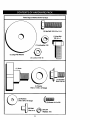
1
Owner's Manual
(RRFTSMAN
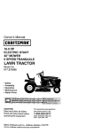
17.0 HP
ELECTRIC START
42" MOWER
AUTOMATIC
LAWN TRACT H
Model No.
917.270722
•
•
•
•
EZ
Safety
Assembly
Operation
Maintenance
• Repair Parts
CAUTION:
Read and follow all
Safety Rules and Instructions
before operating this equipment.
Seam,
For answers to your questions
about this product, Call:
1-800-659-5917
Sears Craftsman Help Line
5 am- 5 pm, Mon- Sat
Roebuck and Co., Hoffman Estates, IL 60179
Maintenance ......................................... 18
Service and Adjustments ...................... 22
Storage ................................................. 28
Troubleshooting.................................... 29
Repair Parts ......................................... 32
Pads Ordedng ....................... Back Cover
Warranty ................................................. 2
Safety Rules .......................................... .2
Product Specifications ........................... 5
Assembly ................................................ 8
Operation .............................................. 11
Maintenance Schedule ......................... 18
..LIMITED TWO YEAR WARRANTY ON CRAFTSMAN RIDING EQUIPMENT
For two(2) years from the date of purchase, if this Craftsman Riding Equipment is maintaih_d, lubricated and tuned up according to the instructionsin the owner's manual,
•Seam will repair or replace, free of charge, any pa.ds found to be defective in material or
workmanship.
This Warranty does not cover,
o._:
• Expendable items which become worn during normal use, such as blades, spark
plugs, air cleaners, belts, etc.
• Tire replacement or repair caused by punctures from outside objects, such as nails,
thorns, stumps, or glass.
• Repairs necessary because of operator abuse, negligence, improper storage or accident or the failure to maintain the equipment according to the instructions contained in
the owner's manual.
• Riding equipment used for commemial or rental purposes.
LIMITED
90 DAY WARRANTY
ON BA'I-I'ERY
For ninety (90) days from date of purchase, if any battery included with this riding equipment proves defective in material or workmanship and our testing determines the battery will not hold a charge, Sears will replace the battery at no charge. In-home warranty
service on your Craftsman riding equipment is available at no charge for 30 days from
the date of purchase. Please contact your nearest service center. After 30 days from the
date of purchasa, warranty service is available by taking your Craftsman riding equipment to your nearest Sears Service Center. (In-home warranty service will still be available after 30 days from the date of purchase but a standard trip charge will apply). This
warranty applies only while this product is in the United States. This Warranty gives you
specific legal rights, and you may also have other rights which may vary from state to
state.
Sears, Roebuck and Co., D/817 WA, Hoffman Estates, IL 60179
GENERAL OPERATION
• Never carry passengers.
• Do not mow in reverse unless absolute-
• Read, understand, and follow all instructions in the manual and on the machine
before starting.
• Only allow responsible adults, who are
familiar with the instructions, to operate
the machine.
ly necessary. Always look down and
behind before and while backing.
• Be aware of the mower discharge direction and do not point it at anyone. Do
not operate the mower without either
the entire grass catcher or the guard in
place.
• Slow down before tuming.
• Never leave a running machine unattended. Always turn off blades, set parking brake, stop engine, and remove
keys before dismounting.
• Clear the area of objects such as recks,
toys, wire, etc., which could be picked
up and thrown by the blade.
• Be sure the area is clear of other people
befo_mowing.
Stop machine if anyone
enters the area.
2
• Do nottry to stabilize the machine by
putting your foot on the ground.
• Do not use grass catcher on steep
slopes.
•Tum
off blades when not mowing.
• Stop engine before removing grass
catcher or unclogging chute.
• Mow only in daylight or good artificial
light.
• Do not operate the machine while under
the influence of alcohol or drugs.
•
Watch for traffic when operating near or
crossing roadways.
• Use extra care when loading or unloading the machine into a trailer or truck.
SLOPE
CHILDREN
Tragic accidents can occur ifthe operator
is not alert to the presence of children.
Children are often attracted to the
machine and the mowing activity. Never
assume that children will remain where
you last saw them.
• Keep children out of the mowing area
and under the watchful care of another
responsible adult.
• Be alert and turn machine off if children
enter the area.
• Before and when backing, look behind
and down for small children.
• Never carry children. They may fall off
and be seriously injured or interfere with
safe machine operation.
• Never allow children to operate the
machine.
• Use extra care when approaching blind
comers, shrubs, trees, or other objects
that may obscure vision.
OPERATION
Slopes are a major factor related to lossof-control and tipover accidents, which
can result in severe injury or death. All
slopes require extra caution, If you cannot
back up the slope or if you feel uneasy on
it, do not mow it.
DO:
• Mow up and down slopes, not across.
• Remove obstacles such as rocks, tree
limbs, etc.
• Watch for holes, ruts, or bumps. Uneven
terrain could overturn the machine. Tall
grass can hide obstacles.
• Use slow speed. Choose a low gear so
that you will not have to stop or shift
while on the slope.
• Follow the manufacturer's recommen-
SERVICE
• Use extra care in handling gasoline and
other fuels. They are flammable and
vapors are explosive.
Use only an approved container.
Never remove gas cap or add fuel
with the engine running. Allow engine to coo/before refueling. Do not
smoke.
Never refuel the machine indoors.
Never store the machine or fuel
container inside where there is an
open flame, such as a water heater,
• Never run a machine inside a closed
area.
• Keep nuts and bolts, especially blade
attachment bolts, tight and keep equipment in good condition.
• Never tamper with safety devices.
Check their proper operation regularly.
• Keep machine free of grass, leaves, or
other debris build-up. Clean oil or fuel
spillage. Allow machine to cool before
storing.
• Stop and inspect the equipment if you
strike an object. Repair, if necessary,
before restarting.
dations for wheel weights or counterweights to improve stability.
• Use extra care with grass catchers or
other attachments. These can change
the stability of the machine.
• Keep all movement on the slopes slow
and gradual. Do not make sudden
changes in speed or direction.
• Avoid starting or stopping on a slope. If
tires-lose traction, disengage the blades
and proceed slowly straight down the
slope.
DO NOT:
• Do notturn on slopes unless necessary,
and then, turn slowly and gradually
downhill, if possible.
• Do not mow near drop-offs, ditches, or
embankments. The mower could suddenly turn over if a wheel is over the
edge of a cliff or ditch, or if an edge
caves in.
• Do not mow on wet grass. Reduced
tra,_ion could cause sliding.
3
• Never make adjustments or repaim with
the engine running.
• Grass catcher components are subject
to wear, damage, and deterioration,
which could expose moving pads or
allow objects to be thrown. Frequently
check components and replace with
manufacturer's recommended pads,
when necessary.
• Mower blades are sharp and can cut.
Wrap the blade(s) or wear gloves, and
use extra caution when servicing them.
• Check brake operation frequently.
Adjust and service as required.
• Be sure the area is clear of other people
before mowing. Stop machine if anyone
enters the area.
• Mow up and down slopes (15 ° Max), not
across.
• Remove obstacles such as rocks, tree
limbs, etc.
• Watch for holes, ruts, or bumps. Uneven
terrain could overturn the machine. Tall
• Never carry passengers.
• Do not mow in reverse unless absolutely necessary. Always look down and
behind before and while backing.
• Never carry children. They may fall off
and be seriously injured or interfere with
safe machine operation.
• Keep children out of the mowing area
and under the watchful care of another
• Before and when backing, look behind
and down for small children.
grass can hide obstacles.
• Use slow speed. Choose a low gear so
that you will not have to stop or shift
while on the slope.
• Avoid starting or stopping on a slope. If
tires lose traction, disengage the blades
and proceed slowly straight down the
slope.
• Do not tum on slopes unless necessary,
and then, tum slowly and gradually
downhill, if possible.
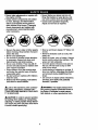
,_,Look for this symbol to point out important safety precautions. It means CAUTION!?! BECOME AWARE!!! YOUR SAFETY IS INVOLVED.
AWARNING:
The engine exhaust from
this product contains chemicals known to
the State of Califomia to cause cancer,
birth defects, or other reproductive harm.
responsible adult.
• Be alert and turn machine off if children
enter the area.
ACAUTION:
In order to prevent accidental starting when setting up, transporting,
adjusting or making repairs always disconnect spark plug wire and place wire where
it cannot contact spark plug.
4
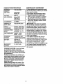
PRODUCT
SPECIFICATIONS
GASOLINE
CAPACITY
AND TYPE:
OIL TYPE
_,PI-SF/SG/SH):
MAINTENANCE
AGREEMENT
A Sears Maintenance Agreement is available on this product. Contact you_"nearest
Sears store for details.
1.25 GALLONS
UNLEADED
REGULAR
CUSTOMER
RESPONSIBILITIES
• Read and observe the safety rules.
• Follow a regular schedule in maintaining, cadng for and using your tractor.
• Follow the instructions under "Maintenance" and =Storage" sections of this
owner's manual.
SAE 30
(above 32°F)
SAE 5W-30
(below 32°F)
DIL CAPACITY:
3.0 PINTS
SPARK PLUG:
[GAP: .030")
Champion RC12YC
VALVE
;LEARANCE:
INTAKE: .003"-.005"
EXHAUST:.005"-.007"
-_ROUND SPEED
FORWARD:
0 - 5.5
MPH):
REVERSE:
0 - 2.4
TIRE PRESSURE:
FRONT: 14 PSI
REAR: 10 PSI
CHARGING
YSTEM:
3 AMPS BAI-I'ERY
5 AMPS HEADLIGHTS
BATTERY:
AMP/HR: 25
MIN. CCA:190
CASE SIZE: U1R
BLADE BOLT
TORQUE:
27-35 FT. LBS.
,AWARNING:
This tractor is equipped
with an internal combustion engine and
should not be used on or near any unimproved forest-covered,
brush-covered or
grass-covered land unless the engine's
exhaust system is equipped with a spark
arrester meeting applicable local or state
laws (if any). If a spark arrester is used, it
should be maintained in effective working
order by the operator.
In the state of California the above is
required by law (Section 4442 of the
California Public Resources Code). Other
states may have similar laws. Federal
laws apply on federal lands. A spark
arrester for the muffler is available through
your nearest Sears Authorized Service
Center (See REPAIR PARTS section of
this manual).
CONGRATULATIONS on your purchase
of a Craftsman Tractor. It has been
designed, engineered and manufactured
to give you the best possible dependability
and performance.
Should you expedence any problem you
cannot easily remedy, please contact your
nearest Sears Authorized Service Center.
We have competent, well-trained techniclans.and the proper tools to service or
repair this tractor.
Please read and retain this manual. The
instructions will enable you to assemble
and maintain your tractor properly. Always
observe the "SAFETY RULES".
5
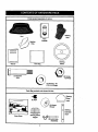
Pads Bag contents shown full size
(1) Hex Bolt 5/16-18 x 1-1/4
3/8-16 x I
(1) Hex Bolt
Lockwasher 3/8
(1) Large Rat Washer
(1) Loci(nut 5/16-18
(1) Knob
(1) Shoulder
Bolt 5/16-18
(1) Washer
17/32 x %3/16 x 12 Gauge
(2) Washers
3/16 x 3/4 x 16 Gauge
_#10
(2)
Weld
Nuts
#10
6
(2) Lock
Washers #10
x 5/8
Partspackedseparatelyin carton
D
Steering
Boot
Seat
Video
Cassette
Mulcher
Plate
I
Manual
Steedng
Wheel
Parts Bag
_(2)
Center-
(2) Shoulder
Bolts
lockNuts
(2) Washers 3/8
x 7/8 x 14 Gauge
Parts Bag contents not shown full size
_
teedng
Wheel
(2) Keys
Insert
Wheels
SlopeSheet
SteeringWheel
Adapter
_--. Steering
Extension
Shaft
ii
(2) Latch Hook
Assernblya
7
0
Yournewtractorhasbeenassembledat the factorywith exceptionof thosepartsleft
unassembledfor shippingpurposes.Toensuresafe andproperoperationof yourtractor
all parts andhardwareyou assemblemustbe tightenedsecurely.Usethe correcttools
as necessaryto insurepropertightness.Reviewthe videocassettebeforeyou begin.
TOOLS REQUIRED FOR
ASSEMBLY
• Assemble large flat washer, 3/8 lock
washer, 3/8 hex belt and tighten securely.
• Snap steering wheel insert into center
of steering wheel.
• Remove protective materials from tractor hood and grill.
IMPORTANT: Check for and remove any
staples in skid that may puncture tires
where tractor is to roll off skid.
- A socket wrench set will make assembly
easier. Standard wrench sizes you need
are listed below.
(1) Utility knife
(1) 9/16" wrench
(1)Pliers
(1) 3/4" wrench
(1) 3/4" Socket
w/drive rachet
(2) 1/2" wrench
(1) Phillips Screw driver
(1) Tire pressure gauge
Insert
When right or left hand is mentioned in
this manual, it means, from your point of
view, when you are in the operating position (seated behind the steering wheel).
TO REMOVE
CARTON
UNPACK
TRACTOR
,_3/8
Lockwasher
_Lt_rgher
Flat
FROM
CARTON
Wheel
• Remove all accessible loose parts and
parts boxes from shipping carton (See
page 6).
• Cut, from top to bottom, along lines on
all four corners of shipping carton, and
lay panels flat.
• Check for any additional loose parts or
boxes and remove.
Extension
Adapter
BEFORE ROLLING TRACTOR OFF
SKID
ATTACH
STEERING
ASSEMBLE
BOOT
WHEEL
EXTENSION
SHAFT AND
• Slide extension shaft onto lower steerTO ROLL TRACTOR OFF SKID (See
Operation section for location and
function of controls)
• Press lift lever plunger and raise attachment lift lever to its highest position.
• Release parking brake by depressing
clutch/brake pedal.
• Place freewheel control in freewheeling
position to disengage transmission (See
"TO TRANSPORT"
in the Operation
section of this manual).
• Roll tractor forward off skid.
ingshaft. Align mounting holes in extension and lower shafts and install 5/16
hex belt and Iocknut. Tighten securely.
IMPORTANT: Tighten bolt and nut securely to 18-22 ft. Ibs. torque.
• Place tabs of steering boot over tab
slots in dash and push down to secure.
iNSTALL STEERING WHEEL
• Position front wheels of the tractor so
they are pointingstraight forward.
• Slide steering wheel adapter onto steering shaft extension.
• Position steering wheel so cross bars
araJ_rizontal
(left to right) and slide
inside boot and onto adapter.
• Remove banding holding discharge
guard up against tractor.
8
CHECK TIRE PRESSURE
The tires on your tractor were overinflated
at the factory for shipping purposes.
Correct tire pressure is important for best
cutting performance.
• Reduce tire pressure to PSI shown in
"PRODUCT SPECIFICATIONS"
on
HOW TO SET UP YOUR TRACTOR
CHECKBATTERY
• Lift seat pan to raised position and open
battery box door.
• If this battery is put into service after
month and year indicated on label (label
located between terminals) charge battery for minimum of one hour at 6-10
amps. (See "BATTERY" in MAINTENANCE section of this manual for
page 5 of this manual.
CHECK
DECK LEVELNESS
For best cutting results, mower housing
should be properly leveled. See "TO
LEVEL MOWER HOUSING" in the
charging instructions).
Service and Adjustments section of this
manual.
Battery
CHECK FOR PROPER
ALL BELTS
Label
Box Door_
INSTALL
POSITION
OF
See the figures that are shown for replacing motion and mower blade drive belts in
the Service and Adjustments sectoin of
this manual. Verify that the belts are muted correctly.
CHECK BRAKE SYSTEM
After you learn how to operate your tractor, check to see that the brake is properly
adjusted. See "TO ADJUST BRAKE" in
the Service and Adjustments section of
this manual.
SEAT
Adjust seat before tightening adjustment
knob.
• Remove cardboard packing on seat
pan.
• Place seat on seat pan and assemble
shoulder bolt. Tighten shoulder bolt
securely.
• Assemble adjustment knob and flat
washer loosely. Do not tighten.
• Lower seat into operating position and
sit on seat.
• Slide seat until a comfortable position is
reached which allows you to press
clutch/brake pedal all the way down.
• Get off seat without moving its adjusted
position.
• Raise seat and tighten adjustment knob
INSTALL MULCHER PLATE
• Install two latch hooks to mulcher plate
using screw, washer, lock washer, and
weld nut as shown.
NOTE: Pre-assemble weld nut to latch
hook by inserting weld nut from the top
with hook pointing down.
• Tighten hardware securely.
• Raise and hold deflector shield in upright position.
• Place front of mulcher plate over front of
mower deck opening and slide into
place, as shown.
• Hook front latch into hole on front of
mower deck.
• Hook rear latch into hole on back of
mower deck.
securaly.
Seat
Seat Pan
ACAUTION:
+
Shoulder
Bolt
•
Do not remove discharge
guard from mower. Raise and hold guard
when attaching mulcher plate and allow it
to rest on plate while in operation.
_ TO CONVERT TO BAGGING OR
DISCHARGING
Simply remove mulcher plate and store in
a safdl_lace. Your mower is now ready for
discharging or installation of optional
grass catcher accessory.
Rat Washer
Adjusl_nentKnob
9
blades. The mulcher blades are _
for discharging and bagging also.
Weld Nut From
The Top
Weld
Ho_ Peints.
Down
Lock
Washer
Latch
3/8-16 Washer
Latch
e Wheel
v' CHECKLIST
PLEASE REVIEW THE FOLLOWING
CHECKLIST:
Lock Washer
Washer
Washer
Mulcher
Plate
Deflector
Shield
V' All assembly instructions have been
completed.
,/ No remaining loose parts in carton.
v' Battery is propedy prepared and
charged. (Minimum I hour at 6 amps).
v' Seat is adjusted comfortably and
tightened securely.
,/ All tires are properly inflated. (For
shipping purposes, the tires were
overinflated at the factory).
v' Be sure mower deck is properly leveled
side-to-side/front-to-rear
for best
Screw
Latch
Hooks
cutting results. (Tires must be properly
inflated for leveling).
,/ Check mower and drive belts. Be sure
they are muted propedy around pulleys
and inside all belt keepers.
I/ Check wiring. See that all connections
are still secure and wires are properly
clamped.
v' Before driving tractor, be sure freewheel control is in drive position.
ASSEMBLE GAUGE WHEELS TO
MOWER DECK
The gauge wheels are designed to keep
the mower deck in proper position when
operating mower. Be sure they are properly adjusted to ensure optimum mower performance.
• Assemble gauge wheels with tractor on
a flat level surface.
• Adjust mower to desired cutting height
(See "TO ADJUST MOWER CUTI'ING
HEIGHT" in the Operation section of
this manual).
• With mower in desired height of cut pesition, gauge wheels should be assembled so they are slightlyoff the ground.
Install gauge wheel in appropdate hole
with shoulder bolt, 3/8 washer, and 3/816 iocknut and tighten securely.
• Repeat for opposite side installing
gauge wheel in same adjustment hole.
WHILE LEARNING HOW TO USE YOUR
TRACTOR, PAY EXTRAA'I-rENTION
TO
THE FOLLOWING IMPORTANT ITEMS:
,/Engine
oil is at proper level.
/ Fuel tank is filled with fresh, clean,
regular unleaded gasoline.
/ Become familiar with all controls - their
location and function. Operate them
before you start the engine.
/ Be sure brake system is in safe operating condition.
/ It is important to purge the transmission before operating your tractor for
the first time. Follow proper starting
and transmission purging instructions
(See "TO START ENGINE" end
"PURGE TRANSMISSION"
in the Op
eration section of this manual).
10
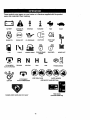
Thesesymbolsmay appearon yourtractoror in literaturesuppliedwith the product.
Learnand understandtheir meaning.
BATI'ERY
CAUTION OR
WARNING
REVERSE
FORWARD
FUEL
CHOKE
MOWER HEIGHT
FAST
PARKING BRAKE
LOCKED
SLOW
UNLOCKED
MOWER LIFT
N H L
A'I-rACHMENT
CLUTCH ENGAGED
REVERSE
NEUTRAL
ATTACHMENT
IGNITION
HIGH
LOW
KEEP AREA CLEAR
CLUTCH DISENGAGED
PARKING BRAKE
SLOPE HAZARDS
(SEE SAFETY RULES SECTION)
FREE WHEEL
DANGER, KEEP HANDS AND FEET AWAY
(Automatic Models only)
11
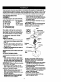
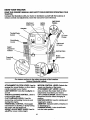
KNOW
YOUR TRACTOR
READ THIS OWNER'S MANUAL AND SAFETY RULES BEFORE OPERATING YOUR
TRACTOR
Compare the illustrations with your tractor to familiarize yourself with the locations of
various controls and adjustments. Save this manual for future reference.
Attachment
Clutch Lever
IgnlUon
Switch
Light Switch
Position
Ammeter
Throttle/Choke
Control
Lift Lever
Plunger
Clutch/Brake
Control
Attachment
Lift Lever
Height
Adjustment
Indicator
Brake
Motion
Control Lever
Freewheel
Control
Our tractors conformto the safety standards of the American
National Standards Institute.
ATTACHMENT
CLUTCH
LEVER: Used to
MOTION
CONTROL
LEVER: Selects the
engage the mower blades, or other attachments mounted to your tractor.
LIGHT SWITCH: Tums the headlights on
and off.
THROTTLE/CHOKE
CONTROL: Used to
speed and direction of the tractor.
ATTACHMENT
LIFT LEVER: Used to
raise and lower the mower deck or other
control engine speed.
CLUTCH/BRAKE
PEDAL:
attachment lift lever when changing its
position.
IGNITION SWITCH: Used for starting and
stopping the engine.
AMMETER: Indicates battery charging (+)
or discharging (-).
PARKING BRAKE: Locks clutch/brake
attachments mounted to your tractor.
UFT LEVER PLUNGER: Used to release
Used for
declutching and braking the tractor and
starting the engine.
FREEWHEEL
CONTROL: Disengages
transmission for I_ushing or slowly towing
the tractor with the engine off.
HEIGHT ADJUSTMENT
KNOB: Used to
adju_"f_e mower cutting height.
into the brake position.
12
The operationof anytractorcan resultin foreignobjectsthrownintothe
eyes, which can result in severe eye damage. Always wear safety glasses
or eye shields while operating your tractor or performing any adjustments or
repairs. We recommend a wide vision safety mask over spectacles, or standard safety glasses.
HOW TO USE YOUR TRACTOR
Your tractor is equipped with an operator
presence sensing switch. When engine is
running, any attempt by the operator to
leave the seat without first setting the
parking brake will shut off the engine.
TO SET PARKING
BRAKE
• Depress clutch/brake pedal into full
"BRAKE" position and hold.
• Place parking brake lever in =ENGAGED" position and release pressure
from clutch/brake pedal. Pedal should
remain in =BRAKE" position. Make sure
parking brake will hold tractor secure.
Attachment Clutch
Throttle/Choke
Lever "Engaged"
Control
Position
=Disengaged"
"Brake"
Position
/_
,
Parking Brake
',
Pedal =Drive"
Position
=Disengaged"
Position
Position
Motion
Control
Lever
STOPPING
MOWER BLADES • To stop mower blades, move attachment clutch lever to =DISENGAGED"
position.
GROUND
use.
• Never usa choke to stop engine.
IMPORTANT:
Leaving the ignition switch
in any position other than =OFF" will cause
the battery to be discharged, (dead).
NOTE: Under certain conditions when
tractor is standing idle with the engine running, hot engine exhaust gases may
cause =browning" of grass. To eliminate
this possibility, always stop engine when
stopping tractor on grass areas.
_, CAUTION:
Always stop tractor completely, as described above, before leaving
the operator's position; to empty grass
catcher, etc.
THROTTLE CONTROL
Always operate engine at full throttle.
• Operating engine at less than full throttle reduces the battery charging rate.
• Full throttle offers the best bagging and
mower performance.
TO MOVE FORWARD AND BACKWARD
The direction and speed of movement is
controlled by the motion control lever.
• Start tractor with motion control lever in
neutral (N) position.
• Release parking brake and clutch/brake
pedal.
• Slowly move motion control lever to
desired position.
NOTE: The effort to move the motion control lever will reduce after the first few
hours of use. This is normal.
TO ADJUST MOWER CUTTING HEIGHT
The cutting height is controlled by turning
the height adjustment knob in desired
direction.
DRIVE -
• To stop ground drive, depress
clutch/brake pedal into full "BRAKE"
position.
_ _,:-Movemotion control lever to neutral (N)
position.
IMPORTANT:
The motion control lever
does not retum to neutral (N) position
when the dutch/brake pedal is depressed.:
ENGINE
• Turn ignition key to =OFF" position and
remove key. Always remove key when
leaving tractor to prevent unauthorized
-
_'' Turn knob clockwise (C,) to raisa cutting
height.
•Tum
knob counterclockwise (,.._)to
lower cuttin_ height.
The curing height range is approximately
1-1/2" to4". The heights are measured
from the ground to the blade tip with the
engine not running. These he,ghts are approximate and may vary depending upon
soil conditions, height of grass andtypes
of grass being mowed.
• Move throttle control to slow position.
NOTE: Failure to move throttle control to
slow position and allowing engine to idle _
before stopping may cause engine to
13
"backfire".
• The averagelawn shouldbe cut to
opproximately
2-1/2 inches dudng the
cool season and to over 3 inches during
hot months. For healthier and better
looking lawns, mow often and after
moderate growth.
• For best cutting performance, grass
over 6 inches in height should be
mowed twice. Make the first cut rela-tively high; the second to desired height.
TO OPERATE MOWER
Your tractor is equipped with an operator
presence sensing switch. Any attempt by
the operator to leave the seat with the
engine running and the attachment clutch
engaged will shut off the engine.
• Select desired height of cut.
• Lower mower with attachment lift control.
• To restarrmovement, slowly release
parking brake and clutch/brake pedal.
• Slowly move motion control lever to
slowest setting.
• Make all tums slowly.
TO TRANSPORT
When pushing or towing your tractor, be
sure to disengage transmission by placing
freewheel control in freewheeling position.
Freewheel control is located at the rear
drawbar of tractor.
• Raise attachment lift to highest position
with attachment lift control.
• Pull freewheel control knob out and hold
in position by inserting retainer spring
into forward hole of control rod.
• Do not push or tow tractor at more than
two (2) MPH.
• To reengage transmission, reverse
above procedure.
NOTE: To protect hood from damage when
transporting your tractor on a truck or a
trailer, be sure hood is closed and secured
to tractor. Use an appropriate means of
tying hood to tractor (rope, cord, etc.).
• Start mower blades by engaging attachment clutch control.
• TO STOP MOWER BLADES - disengage attachment clutch control.
Attachment Clutch
Lever =Engaged"
"Disengaged"
Attachment Lift
Lever High Position
,_
Low
_uard
TOWING CARTS AND OTHER
ATTACHMENTS
Tow only the attachments that are recommendedby and comply with specifications
of the manufacturer of your tractor. Use
common sense when towing. Too heavy of
a load, while on a slope, is dangerous.
Tires can lose traction with the ground and
cause you to lose control of your tractor.
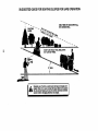
TO OPERATE ON HILLS
_,CAUTION:
Do not drive up or down
hills with slopes greater than 15° and do
not drive acr-ossany slope. Use the slope
guide provided at the back of this manual.
• Choose the slowest speed b_fore starting up or down hills.
• Avoid stopping or changing speed on
hills.
• If slowing is necessary, move throttle
control lever to slower position.
• If stopping is absolutely necessary, push
clutch/brake pedal quickly to brake position and engage parking brake.
• Move motion control lever to neutral (N)
position.
IMPORTANT: The motion control lever
does noL.-mtumto neutral (N) position
when the clutch/brake pedal is depressed.
BEFORE STARTING THE ENGINE
CHECK ENGINE OIL LEVEL
• The engine in your tractor has been
shipped, from the factory, already filled
with summer weight oil.
• Check engine oil with tractor on level
ground.
• Remove oil fill cap/dipstick and wipe
clean, reinsert the dipstick and screw
cap tight, wait for a few seconds,
remove and read oil level. If necessary,
add oil until =FULL" mark on dipstick is
reached. Do not overfill.
14
•
For cold weather operation you should
change oil for easier starting (See "OIL
VISCOSITY CHART" in the Maintenance section of this manual).
• To change engine oil, see the Maintenance section in this manual.
ADD
GASOLINE
• Fill fuel tank. Use fresh, clean, regular
unleaded gasoline with a minimum of 87
octane. (Use of leaded gasoline will
increase carbon and lead oxide
deposits and reduce valve life). Do not
mix oil with gasoline. Purchase fuel in
quantities that can be used within 30
days to assure fuel freshness.
IMPORTANT: When operating in temperatures below 32°F(0°C), use fresh, clean
winter grade gasoline to help insure good
cold weather starting.
,AWARNING:
Experience indicates that
alcohol blended fuels (called gasohol or
using ethanol or methanol) can attract
moisture which leads to separation and
formation of acids during storage. Acidic
gas can damage the fuel system of an
engine while in storage. To avoid engine
problems, the fuel system should be emptied before storage of 30 days or longer.
Drain the gas tank, start the engine and let
it run until the fuel lines and carburetor are
empty. Use fresh fuel next season. See
Storage Instructions for additional information. Never use engine or carburetor
cleaner products in the fuel tank or permanent damage may occur.
A, CAUTION: Fill to bottom of gas tank
filler neck. Do not overfill. Wipe off any
spilled oil or fuel. Do not store, spill or use
gasoline near an open flame.
TO START ENGINE
When starting the engine for the first time
or if the engine has run out of fuel, it will
take extra cranking time to move fuel from
the tank to the engine.
• Be sure freewheel control is in the
transmission engaged position.
• Sit on seat in operating position,
depress clutch/brake pedal and set
parking brake.
• Place motion control lever in neutral (N)
position.
• Move attachment clutch to =DISENGAGED" position.
• Move throttle control to choke position.
NOTE: Before starting, read the warm and
cold'St_rting procedures below.
• Insert key into ignition and turn key
clockwise to "START" position and
release key as soon as engine starts.
Do not run starter continuously for more
than fifteen seconds per minute, if the
engine does not start after several
attempts, move throttle control to fast
position, wait a few minutes and try
again. If engine still does not start,
move the throttle control back to the
choke position and retry.
WARM WEATHER STARTING (50 ° F and
above)
• When engine starts, move the throttle
control to the fast position.
• The attachments
and ground drive can
now be used. If the engine does not
accept the load, restart the engine and
allow it to warm up for one minute using
the choke as described above.
COLD WEATHER STARTING ( 50 ° F and
below)
• When engine starts, allow engine to run
with the throttle control in the choke
position until the engine runs roughly,
then move throttle control to fast position. This may require an engine warmup period from several seconds to several minutes, depending on the temperature.
AUTOMATIC TRANSMISSION
WARM UP
• Before driving the unit in cold weather,
the transmission should be warmed up
as follows:
Be sure the tractor is on level _mund.
Place the motion control lever m neutral.
Release the parking brake and let the
clutch/brake slowly retum to operating
position.
• Allow one minute for transmission to
warm up. This can be done during the
engine warm up period.
• The attachments can also be used during the engine warm-up period after the
transmission has been warmed up.
NOTE: At a high altitude (above 3000
feet) or in cold temperatures (below 32 F)
the carburetor fuel mixture may need to be
adjusted for best engine performance.
See =TO ADJUST CARBURETOR"
in the
Sewice and Adjustments section of this
manual.
15
PURGETRANSMISSION
,ACAUTION:
Never engage or disengage freewheel lever while the engine is
running.
To ensure proper operation and performance, it is recommended that the transmission be purged before operating tractor
for the first time. This procedure will
remove any trapped air inside the trans" mission which may have developed during
shipping of your tractor.
IMPORTANT:
Should your transmission
require removal for service or replacement, it should be purged after reinstallation before operating the tractor.
• Place tractor safely on level surface with
engine off and parking brake set.
• Disengage transmission by placing freewheel control in freewheeling position
(See "TO TRANSPORT"
in this section
of manual).
• Sitting in the tractor seat, start engine.
After the engine is running, move throttle control to slow position. With motion
control lever in neutral (N) position,
slowly disengage clutch/brake pedal.
• Move motion control lever to full forward
position and hold for five (5) seconds.
Move lever to full reverse position and
hold for five (5) seconds. Repeat this
procedure three (3) times.
NOTE: During this procedure there will be
no movement of drive wheels. The air is
being removed from hydraulic drive system.
• Move motion control lever to neutral (N)
position. Shut off engine and set parking
brake.
• Engage transmission by placing freewheel control in driving position (See
=TO TRANSPORT"
in this section of
mantlal).
• Sitting in the tractor seat, stad engine.
After the engine is running, move throttle control to half (1/2) speed. With
motion control lever in neutral (N) position, slowly disengage clutch/brake
pedal.
• Slowly move motion control lever forward; after the tractor moves approximately five (5) feet, slowly move motion
control lever to reverse position. After
the tractor moves approximately five (5)
feet return the motion control lever to
the neutral (N) position. Repeat this proceddre with the motion control lever
three (3) times.
• Your tractor is now purged and ready for
normal operation.
MOWING
TIPS
• Tire chains cannot be used when the
mower housing is attached to tractor.
• Mower should be propedy leveled for
best mowing performance.
See "TO
LEVEL MOWER HOUSING" in the
Service and Adjustments section of this
manual.
• The left hand side of mower should be
used for trimming.
• Drive so that clippings are discharged
onto the area that has been cut. Have
the cut area to the right of the tractor.
This will result in a more even distribution of clippings and more uniform cutting.
• When mowing large areas, stad by tuming to the right so that clippings will discharge away from shrubs, fences, driveways, etc. After one or two rounds, mow
in the opposite direction making left
hand tums until finished.
• If grass is extremely tall, it should be
mowed twice to reduce load and possible fire hazard from dried clippings.
Make first cut relatively high; the second
to the desired height.
• Do not mow grass when it is wet. Wet
grass will plug mower and leave undesirable clumps. Allow grass to dry
before mowing.
• Always operate engine at full throttle
when mowing to assure better mowing
performance and proper discharge of
material. Regulate ground speed by selecting a low enough gear to give the
mower the best cutting performance as
well as the quality of cut desired.
• When operating attachments, select a
ground speed that will suit the terrain
and give best performance of the attachment being used.
[
I
t
16
MULCHING MOWING TIPS
IMPORTANT:Forbest performance,keep
mowerhousingfree of built-upgrassand
trash.Cleanaftereachuse.
• The specialmulchingbladewill recut
the grassclippingsmanytimes and
reducethem in size so that as they fall
ontothe lawnthey will disperseintothe
grassand not be noticed. Also, the
mulched grass will biodegrade quickly
to provide nutrients for the lawn. Always
mulch with your highest engine (blade)
speed as this will provide the best recutring action of the blades.
• Avoid cutting your lawn when it is wet.
Wet grass tends to form clumps and
interferes with the mulching action. The
best time to mow your lawn is the early
aftemoon. At this time the grass has
dried and the newly cut area will not be
exposed to the direct sun.
• For best results, adjust the mower cutting height so that the mower cuts off
only the top one-third of the grass
• blades. For extremely heavy mulching,
reduce your width of cut on each pass
and mow slowly.
• Certain types of grass and grass conditions may require that an area be
mulched a second time to completely
hide the clippings. When doing a second cut, mow across or perpendicular to
the first cut path.
• Change your cutting pattem from week
to week. Mow north to south one week
then change to east to west the next
week. This will help prevent matting and
graining of the lawn,
17
CUSTOMER
RESPONSIBILITIES
3ERVICE
DATES
iv"
#-djust
*_otion
Drive
Check
Engine
Oil Level
Change
Engine
Air Filter
Clean
Air Screen
;qepiace
C!ean
Muffler/Spark
Oil Filter
ENgine
Tension
Oil
Clean
!nspect
Belt(s)
Arrester
(If equipped)
Coo;i'_,g FiRs
'!:(: v,auanty on thi_ tractor does ;',or cover
iL_ms that i_ave been subjected to operator
_bus_._ or negligence. To receive full value
hem lhe warranty, operator must maintain
tractor as instructed in this manual. Some
_djustments will need to be made periodically to properly maintain your tractor.
_dl adjustments in the Service and
Ac',iustmen_ts section of this manual should
be checked at least once each season•
* Once a year you should replace the
spark plug, clean or replace air filter, and
check blades and belts for wear. A new
spark plug and clean air filter assure
proper air-fuel mixture and help your
engine run better and last longer.
BEFORE
•
•
•
,
EACH USE
Check engine oil level.
Check brake operation.
Check tire pressure.
Check operator presence and interlock
system_.for proper operation.
, Check for loose fasteners.
_=
e r-rent
Wh_el.
Bearing
Whee'
Bearing
Zerk
_) Engine
O A_achm_
Clutch
Pivot(s)
O SAE 30 or 10w30 Motor OIL
_1 General Purpose Grease
Refer to Maintenance "Engine" Section
IMPORTANT:
Do not oil or grease the pivot
points which have special nylon bear-ings.
Viscous lubricants will attract dust and dirt
that will shorten the life of the self-lubricating
bearings. If you feel they must be lubricated,
use only a dry, powdered graphite type lubricant sparingly.
18
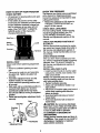
TRACTOR
NOTE: Make sure center hole in blade
Always observe safety rules when performing any maintenance.
BRAKE OPERATION
aligns with star on mandrel assembly.
• Reassemble hex bolt, lock washer and
flat washer in exact order as shown.
• Tighten bolt securely (27-35 Ft. Lbs.
If tractor requires more than six (6) feet
stopping distance at high speed in highest
gear, then brake must be adjusted. (See
"TO ADJUST BRAKE" in the Service and
Adjustments section of this manual).
-TIRES
• Maintain proper air pressure in all tires
(See "PRODUCT SPECIFICATIONS"
on page 5 of this manual).
• Keep tires free of gasoline, oil, or insect
control chemicals which can harm rubber.
• Avoid stumps, stones, deep ruts, sharp
objects and other hazards that may
cause tire damage.
NOTE: To seal tire punctures and prevent
flat tires due to slow leaks, tire sealant
may be purchased from your local parts
dealer. Tire sealant also prevents tire dry
rot and corrosion.
OPERATOR
PRESENCE SYSTEM
Be sure that operator presence and interlock systems are working properly. If your
tractor does not function as described
below, repair the problem immediately.
• The engine should not start unless the
clutch/brake pedal is fully depressed
and attachment clutch control is in the
disengaged position.
• When the engine is running, any
attempt by the operator to leave the
seat without first setting the parking
brake should shut off the engine.
• When the engine is running and the
attachment clutch is engaged, any
attempt by the operator to leave the
seat should shut off the engine.
• The attachment clutch should never
operate unless the operator is in the
seat.
BLADE CARE
For best results mower blades must be
torque).
IMPORTANT:
Blade bolt is Grade 8 heat
treated.
Mandrel Assembly
Trailing Edge Up
.Blade
Center
hole
Lock
Washer
Star
Flat Washer
Hex Bolt (Grade 8)*
*A Grade 8 heat treated bolt can be
identified by six lines on the bolt head.
TO SHARPEN BLADE
NOTE: We do not recommend sharpening
blade, but if you do, be sure the blade is
balanced.
Care should be taken to keep the blade
balanced. An unbalanced blade will cause
excessive vibration and eventual damage
to mower and engine.
• The blade can be sharpened with a file
or on a grinding wheel. Do not attempt
to sharpen while it is on the mower.
• To check blade balance, you will need a
5/8" diameter steel bolt, pin, or a cone
balancer. (When using a cone balancer,
follow the instructions supplied with balancer).
NOTE: Do not use a nail for balancing
blade. The lobes of the center hole may
appear to be centered, but are not.
• Slide blade onto an unthreaded portion
of the steel bolt or pin and hold the bolt
or pin parallel with the ground. If blade
is balanced, it should remain in a horizontal position. If either end of the blade
moves downward, sharpen the heavy
end until the blade is balanced.
Center Hole
kept sharp. Replace bent or damaged
blades.
BLADE REMOVAL
Blade
• Raise mower to highest position to allow
access to blades.
• Remove hex bolt, lock washer and flat
washer securing blade.
• Install new or resharpened blade with
trst_
edge up towards deck as shown.
5/8* Bolt
or Pin
BATTERY
Your tractor has a battery charging system
which is sufficient for normal use.
19
However,periodicchargingof the battery
withan automotivechargerwill extendits
life.
• Keepbatteryandterminalsclean.
• Keepbatteryboltstight.
SH. Select the oil's SAE viscosity grade
according to your expected operating temperature.
• Keep small vent holes open.
• Recharge at 6-10 amperes for 1 hour.
TO CLEAN
BATTERY AND TERMINALS
Corrosion and dirt on the battery and terminals can cause the battery to =leak _
- power.
• Open battery box door.
• Disconnect BLACK battery cable first
then RED battery cable and remove
battery from tractor.
• Rinse the battery with plain water and
dry.
• Clean terminals and battery cable ends
with wire brush until bright.
• Coat terminals with grease or petroleum
jelly.
• Reinstall battery (See =REPLACING
BATTERY" in the SERVICE AND
ADJUSTMENTS
section of this manual).
NOTE: Although multi-viscosity oils
(5W30, 10W30 etc.) improve starting in
cold weather, these multi-viscosity oils will
result in increased oil consumption when
used above 32°1=. Check your engine oil
level more frequently to avoid possible
engine damage from running low on oil.
Change the oil after every 25 hours of
operation or at least once a year if the
tractor is not used for 25 hours in one
year.
Check the crankcase oil level before starting the engine and after each eight (8)
hours of operation. Tighten oil fill cap/dipstick securely each time you check the oil
level.
V-BELTS
Check V-belts for deterioration
and wear
TO CHANGE
after 100 hours of operation and replace if
necessary. The belts are not adjustable.
Replace belts if they begin to slip from
wear.
TRANSAXLE
OIL
Determine temperature range expected
before oil change. All oil must meet API
service classification SF, SG or SH.
• Be sure tractor is on level surface.
COOLING
• Oil will drain more freely when warm.
• Catch oil in a suitable container.
The transmission fan and cooling fins
should be kept clean to assure proper
cooling.
Do not attempt to clean fan or transmission while engine is running or while the
transmission is hot.
• Inspect cooling fan to be sure fan
blades are intact and clean.
• Remove oil fill cap/dipstick. Be careful
not to allow dirt to enter the engine
when changing oil.
• Remove drain plug.
• After oil has drained completely, replace
oil drain plug and tighten securely.
• Refill engine with oil through oil fill dipstick tube. Pour slowly. Do not overfill.
For approximate capacity see "PRODUCT SPECIFICATIONS"
on page 5 of
this manual.
• Inspect cooling fins for dirt, grass clippings _andother materials. To prevent
damage to seals, do not use compressed air or high pressure sprayer to
clean cooling fins.
TRANSAXLE
PUMP FLUID
• Use gauge on oil fill cap/dipstick for
checking level. Be sure dipstick cap is
tightened securely for accurate reading.
Keep oil at "FULL" line on dipstick.
The transaxle was sealed at the factory
and fluid maintenance is not required for
the life of the transaxle. Should the
transaxle ever leak or require servicing,
contact your nearest authorized service
center.
Cap/Dipstick
ENGINE
Oil
Oil
Fill
Drain
Plug
LUBRICATION
On_
high quality detergent oil rated
with API service classification SF, SG or
ENGINE
20
CLEAN
ENGINE
AIR SCREEN
Air screen must be kept free of dirt and
chaff to prevent engine damage from overheating. Clean with a wire brush or compressed air to remove dirt and stubborn
dded gum fibers.
AIR FILTER
Your engine will not run propedy using a
dirty air filter. Clean the foam pre-cleaner
- after every 25 hours of operation or every
season. Sewice paper cartridge every 100
hours of operation or every season,
whichever occurs first.
COOLING
FINS
Remove any dust, dirt or oil from engine
cooling fins to prevent engine damage
from overheating.
• Remove screws from blower housing
and lift housing and dipstick tube
assembly off engine.
• Cover oil fill opening to prevent entry of
dirt.
• Use compressed air or stiff bdstle brush
to thoroughly clean engine cooling fins.
• To reassemble, reverse above procedure.
Service air cleaner more often under dusty
conditions.
Blower Housing
Screws
Screws
• Remove knob(s) and cover.
TO SERVICE PRE-CLEANER
•
•
•
•
Slide foam pre-cleaner off cartridge.
Wash it in liquid detergent and water.
Squeeze it dry in a clean cloth.
Saturate it in engine oil. Wrap it in clean,
absorbent cloth and squeeze to remove
excess oil.
• If very dirty or damaged,
cleaner.
air screen
DipstickTube
Assembly
replace pre-
• Reinstall pre-cleaner over cartridge.
• Reinstall cover and secure with knob(s).
TO SERVICE CARTRIDGE
• Remove cartridge nut.
• Carefully remove cartridge to prevent
debris from entering carburetor. Clean
base carefully to prevent debris from
entering carburetor.
• Clean cartridge by tapping gently on flat
surface. If very dirty or damaged,
replace cartridge.
• Reinstall cartridge, nut, precleaner,
cover and secure with knob(s).
IMPORTANT:
Petroleum solvents, such as
kerosene, are not to be used to clean the
cartddge. They may cause deterioration of
the cartridge. Do not oil cartddge. De not
use pressurized air to clean_or dry cartddge.
Cover
Knob
C
_
Pre-Cleaner/_
Spark
Plug
Engine Cooling Fins
MUFFLER
Inspect and replace corroded muffler and
spark arrester (if equipped) as it could create a fire hazard and/or damage.
SPARK
Replace spark plugs at the beginning of
each mowing season or after every 100
hours of operation, whichever occurs first.
Spark plug type and gap setting are
shown in "PRODUCT
SPECIFICATIONS"
on page 5 of this manual.
IN-LINE
FUEL
FILTER
The fuel filter should be replaced once
each season. If fuel filter becomes
Cartridge
_
PLUGS
clogged, obstructing fuel flow to carburetor, replacement is required.
• With engine cool, remove filter and plug
fuel line sections.
• Place new fuel filter in position in fuel
line with arrow pointing towards carburetor.
• Be sure there are no fuel line leaks and
clam.ps are propedy positioned.
Paper
21
_
Filter
CLEANING
• Clean engine, battery, seat, finish, etc.
" of all foreign matter.
• Keep finished su,'faces and _-=ele free
of all gasorme, oil, etc.
• Protect painted surfaces with automob_e type wax.
We do not recommend using a garden
hose to cleen your tractor unless the electrical system, muffler, air filter and carburetor are covered to keep water out. Water
in engine can result in a shortened engine
life.
_,CAUTION:
Before performing any service or adjustments:
• Depress clutch/brake pedal fully and set parking brake.
• Place motion control lever in neutral (N) position.
• Place attachment clutch in =DISENGAGED"
position.
• Tum ignition key "OFF" and remove key.
• Make sure the blades and all moving parts have completely stopped.
• Disconnect spark plug wire from spark plug and place wire where it cannot come
in contact with plug.
TO REMOVE
MOWER
• Disconnect front links from deck by
removing retainer springs.
• Raise lift lever to raise suspension
arms. Slide mower out from under tractor.
IMPORTANT:
If an attachment other than
the mower deck is to be mounted on the
Mower will be easier to remove from the
right side of tractor.
• Place attachment clutch in uDISENGAGED" position.
• Move attachment lift lever forward to
lower mower to its lowest position.
• Roll belt off engine pulley.
• Disconnect clutch rod from clutch lever
by removing retainer spring.
• Disconnect anti-swaybar from chassis
bracket by removing retainer spring.
• Disconnect suspension arms from rear
deck brackets by removing retainer
springs.
tractor, remove the front links.
TO INSTALL MOWER
• Raise attachment lift lever to its highest
position.
• Slide mower under tractor with discharge guard to right side of tractor.
• Lower lift lever to its lowest position.
• Install mower in reverse order of
removal instructions,
Retainer
Suspension
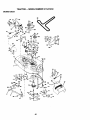
Arms
Clutch
Pulley
Front
Link
(Both Sides)
Retainer
(BothS_des)
spdng
,_ti-Swaybar
22
TO LEVELMOWERHOUSING
Adjustthe mowerwhiletractoris parked
on levelgroundor driveway. Makesure
tires are properlyinflated(See=PROD-
• Before making any necessary adjustments, check that both front links are
equal in length. Both links should be
approximately 10-3/8".
UCT SPECIFICATIONS').
If tires are
over or underinflated, you will not properly
adjust your mower.
SIDE-TO-SIDE
ADJUSTMENT
• Raise mower to its highest position.
• At the midpoint of both sides of mower,
measure height from bottom edge of
mower to ground.
Distance _A" on both
sides of mower should be the same or
within 1/4" of each other.
•
•
•
•
If adjustment is necessary, make adjustment on one side of mower only.
• To raise one side of mower, tighten lift
link adjustment nut on that side.
• To lower one side of mower, loosen lift
link adjustment nut on that side.
•
one
linkare
to same
length
as otheradjust
link.
If links
not equal
in length,
To lower front of mower loosen nut "E"
on both front links an equal number of
turns.
When distance "D" is 1/8" to 1/2" lower
at front than rear, tighten nuts "F"
against trunnion on both front links.
To raise front of mower, loosen nut "F"
from trunnion on both front links.
Tighten nut "E" on both front links an
equal number of tums.
When distance "D" is 1/8" to 1/2" lower
at front than rear, tighten nut "F" against
trunnion on both front links.
Recheck side-to-side adjustment.
_=_
_..
-_____Mandrel
NOTE:
Each full turn of adjustment nut
will change mower height about 1/8".
• Recheck measurements
after adjusting.
Bottoro
Both Front Links Should be Equal in Length
Suspension
Arm
Nut =F" _
Lift Link Adjustment Nut
FRONT-TO-BACK
Nut =E"
Trunnion f_
ADJUSTMENT
Front Links
IMPORTANT:
Deck must be level side-toside. If the followingfront-to-back
adjustment is necessary, be sure to adjust both
front links equally
so mc)wer will stay
level side-to-side.
TO REPLACE
MOWER
BLADE
DRIVE
BELT (See Illustration
Next Page)
The mower blade drive belt may be
replaced without tools. Park the tractor on
level surface. Engage parking brake.
To obtain the best cutting results, the
mower housing should be adjusted so that
the front is approximately 1/8" to 1/2"
lower than the rear when the mower is in
its highest position.
Check adjustment on ri._ht side of tractor.
Measure distance =D" d=rectly in front and
behind the mandrel at bottom edge of
mower housing as shown.
BELT REMOVAL
• Remove mower from tractor (See "TO
REMOVE MOWER" in this section of
this manual).
• Work belt off both mandrel pulleys and
idler pulleys,
• Pull belt away from mower.
23
BELT INSTALLATION
• Install new belt in reverse order of
removal.
• Make sure belt is in all pulley grooves
and inside all belt guides.
• Install mower in reverse order of
removal instructions.
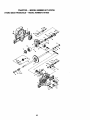
Idler
Pulleys
Mandrel
Mandrel
Pulley
TO ADJUST
TO REPLACE
BRAKE
Your tractor is equipped with an adjustable
brake system which is mounted on the
side of the transaxle.
If tractor requires more than six (6) feet
stopping distance at high speed in highest gear, then brake must be adjusted.
• Depress clutch/brake pedal and engage
parking brake.
• Measure distance between brake operating arm and nut "A" on brake rod.
• If distance is other than 1-9/16", loosen
jam nut and turn nut =A" until distance
becomes 1-9/16". Retighten jam nut
against nut "A".
• Road test tractor for proper stopping
distance as stated above. Readjust if
necessary. If stopping distance is still
greater than six (6) feet in highest gear,
further maintenance is necessary.
Contact your nearest authodzed service center/department.
Jam
With parking Brake
"Engaged"
MOTION
Park the tractor on level surface. Engage
parking brake. For assistance, there is a
belt installation guide decal on bottom side
of left footrest.
• Remove mower (See =TO REMOVE
MOWER" in this section of this manual.)
• Remove belt from stationary idler and
clutching idler.
• Pull belt slack toward rear of tractor.
Carefully remove belt upwards from
transmission input pulley and over cooling fan blades.
• Pull belt toward front of tractor and
remove downward from around engine
pulley.
• Install new belt by reversing above procedure.
Pulley
Clutching
StatJonar_
Transmission
Input Pulley_
Arm
DO Not,_uch his nut. If further brake adjustment is necessary contact your nearest authorizad service center/department
24
DRIVE BELT
TO ADJUST
MOTION
CONTROL
LEVER
The motion control lever has been preset
at the factory and adjustment should not
be necessary.
If for any reason the motion control lever
will not hold its position while at a selected
speed, it may be adjusted at the friction
pack located on the right side of transmission.
• Park tractor on level surface. Stop tractor by turning ignition key to =OFF" position, and engage parking brake.
• Adjust motion control lever by tightening
adjustment Iocknut one half (1/2) turn.
• Repair tire and reassemble.
• On rear wheels only: align grooves in
rear wheel hub and axle, Insert square
key.
• Replace washers and snap retaining
ring securely in axle groove.
• Replace axle cover.
NOTE: To seal tire punctures and prevent
flat tires due to slow leaks, tire sealant
may be purchased from your local parts
dealer, Tire sealant also prevents tire dry
rot and corrosion.
Washers
NOTE: If for any reason the effort to
move the motion control lever becomes
too excessive, reverse the above adjustment procedure by loosening Iocknut 1/4
to 1/2 tum.
Retaining
Ring
Road test tractor after adjustment and
repeat procedure if necessary.
TRANSMISSION
MENT
I
Axle Cover
REMOVAL/REPLACE-
Should your transmission require removal
for service or replacement, it should be
purged after reinstallation and before
operating the tractor. See "PURGE
TRANSMISSION"
in the Operation section
of this manual.
TO START
ENGINE
Square Key
(Rear Wheel Only)
WITH
A WEAK
BATTERY
ACAUTION:
Lead-acid batteries generate explosive gases. Keep sparks, flame
and smoking materials away from batteries. Always wear eye protection when
around batteries.
If your battery is too weak to start the
engine, it should be recharged. (See
"BATTERY" in the MAINTENANCE
section of this manual).
If "jumper cables" are used for emergency
starting, follow this procedure:
IMPORTANT:
Your tractor Is equiped with
a 12 volt negative grounded system. The
other vehical must also be a 12 volt negative grounded system. De not use your
tractor battery to start other vehicals.
Lock,nut
TO ADJUST STEERING WHEEL ALIGNMENT
If steeringwheel crossbars are not hodzontal ([eft to right) when wheels are positioned straight forward, remove steering
wheel and reassemble per instructions in
the Assembly section of this manual.
FRONT WHEEL TOE-IN/CAMBER
The front wheel toe-in and camber are not
TO ATTACH JUMPER CABLES • Connect each end of the RED cable to
the POSITIVE (+) terminal of each battery, taking care not to short against
chassis.
• Connect one end of the BLACK cable to
the NEGATIVE (-) terminal of fully
charged battery.
• Connect the other end of the BLACK
cable to good CHASSIS GROUND,
away from fuel tank and battery.
adjustable on your tractor. If damage has
occurred to affect the front wheel toe-in or
camber, contact your nearest authodzed
service center.
TO REMOVE WHEEL FOR REPAIRS
• Block up axle securely.
• Remove axle cover, retaining ring and
washers to allow wheel removal (rear
wheel contains a square key - Do not
lose).
_,
TO REMOVE
ORDER -
25
CABLES,
REVERSE
• BLACK cable first from chassis and_
then from the fully charged battery.
• RED cable last from both batteries.
PositiveTerminal
Negative Terminal
TO REPLACE HEADLIGHT
BULB
• Raise hood.
• Pull bulb holder out of the hole in the
backside of the grill.
• Replace bulb in holder and push bulb
holder securely back into the hole in the
backside of the grill.
• Close hood.
INTERLOCKS
Loose or damaged widng may cause your
tractor to run poorly, stop running, or prevent it from starting.
• Check wiring. See electrical wiring diagram in the Repair Parts section of this
manual.
Charged
Positive
' Negative
Terminal
REPLACING
TO REPLACE FUSE
BATTERY
Replace with 30 amp automotive-type
plug-in fuse. The fuse holder is located
behind the dash.
ACAUTION:
Do not short battery terminals by allowing a wrench or any other
object to contact both terminals at the
same time. Before connecting battery,
remove metal bracelets, wristwatch
bands, rings,etc.
Positive terminal must be connected first
TO REMOVE HOOD AND GRILL ASSEMBLY
• Raise hood.
• Unsnap headlight wire connector.
Stand in front of tractor. Grasp hood at
sides, tilt toward engine and lift off of
tractor.
• To replace, reverse above procedures.
to prevent sparking from accidental
grounding.
• Lift seat pan to raised position and open
battery box door.
• Disconnect BLACK battery cable first
then RED battery cable and carefully
remove battery from tractor.
• Install new battery with terminals in
same position as old battery.
• First connect RED battery cable to positive (+) terminal with hex bolt and keps
nut as shown. Tighten securely.
• Connect BLACK grounding cable to
negative (-) terminal with remaining hex
bolt and keps nut. Tighten securely.
• Close battery box door.
F-_'_
I _ \_
Hood
Wire ector
ENGINE
Maintenance, repair, or replacement of the
emission control devices and systems,
which are being done at the customers
expense, may be performed by any nonread engine repair establishment or individual. Warranty repairs must be performed by an authorized engine manufacturer's service outlet.
TO ADJUST THROTTLE
CONTROL
CABLE
Battery
Positive (Red) Cable
AND RELAYS
Nut
The throttle control has been preset at the
factory and adjustment should not be necessary. Check adjustment as described
below before loosening cable. If adjustment is necessary, proceed as follows:
Hex Bolt
Negative (Black) Cable
26
PRELIMINARY
• With engine not running, move throttle
control lever from slow to choke position. Slowly move lever from choke to
fast position.
• Check that holes "A" in govemor control lever and hole in governor plate lineup. If holes UA" are not aligned, loosen
clamp screw and move throttle cable
until holes are aligned. Tighten clamp
screw securely.
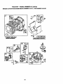
Governor
Govemor
Control Lever
Control Plate
FINAL SETTING
• Start engine and allow to warm for five
minutes. Make final adjustments with
engine running and shift/motion control
lever in neutral (N) position.
• Move throttle control lever to slow position. With finger, rotate and holdthrottle
lever against idle speed screw. Turn
idle speed screw to attain 1750 RPM.
_, While still holding throttle lever against
idle speed screw, turn idle mixture valve
full travel clockwise then counterclockwise until engine runs rough. Tum
valve to a point midway between those
two positions. Release throttle lever.
\
Clamp
Screw
Holes "A"
TO ADJUST
SE'I-I'ING
• Air cleaner assembly must be assembled to the carburetor when making carburetor adjustments.
• Be sure the throttle control cable is
adjusted properly (see above).
ACCELERATION
TEST
• Move throttle control lever from slow to
fast position. If engine hesitates or dies,
tum idle mixture valve out (counterclockwise) 1/8 turn. Repeat test and
continue to adjust, if necessary, until
engine accelerates smoothly.
High speed stop is factory adjusted. Do
not adjust - damage may result.
iMPORTANT:
Never tamper with the
engine governor, which is factory set for
proper engine speed. Overspeeding the
engine above the factory high speed setting can be dangerous. If you think the
engine-govemed high speed needs
adjusting, contact your nearest authorized
service center/department,
which has
proper equipment and experience to make
any necessary adjustments.
Throttle
Cable
CARBURETOR
NOTE: The carburetor on this engine is
low emission. It is equipped with an idle
fuel adjusting needle with a limiter cap,
which allows some adjustment within the
limits allowed by the cap. Do not attempt
to remove the limiter cap. The limifer cap
cannot be removed without breaking the
adjusting needle.
The carburetor has been preset at the factory and adjustment should not be necessary. However, minor adjustment may be
required to compensate for differences in
fuel, temperature, altitude or load. If the
carburetor does need adjustment, proceed
as follows:
In general, turning idle mixture valve in
Idle Speed
Screw
(clockwise) decreases the supply of fuel to
the engine giving a leaner fueVair mixture.
Turning the idle mixture valve out
(counterclockwise) increases the supply of
fuel to the engine giving a richer fuel/air
mixture.
IMPORTANT:
Damage to the needle
valve and the seat in carburetor may
result if screw is tumed in too tight.
Valve _qbh
Umiter
27
Throttle
Lever
Immediately prepare your tractor for storage at the end of the season or if the tractor will not be used for 30 days or more.
A CAUTION: Never store the tractor with
gasoline in the tank inside a building
where fumes may reach an open flame or
. spark. Allow the engine to cool before
storing in any enclosure.
Also, experience indicates that alcohol
blended fuels (called gasohol or using
ethanol or methanol) can attract moisture
which leads to separation and formation of
acids during storage. Acidic gas can damage the fuel system of an engine while in
storage.
• Drain the fuel tank.
• Start the engine and let it run until the
fuel lines and carburetor are empty.
• Never use engine or carburetor cleaner
products in the fuel tank or permanent
damage may occur.
• Use fresh fuel next season.
TRACTOR
Remove mower from tractor for winter
storage. This will allow you to clean it thoroughly. Remove all dirt, grease, leaves,
etc. Store in a clean, dry area.
• Clean entire tractor (See =CLEANING"
in the Maintenance section of this manual).
• Inspect and replace belts, if necessary
(See belt replacement instructions in the
Service and Adjustments section of this
manual).
• Lubricate as shown in the Maintenance
section of this manual.
NOTE: Fuel stabilizer is an acceptable
alternative in minimizing the formation of
fuel gum deposits during storage. Add stabilizer to gasoline in fuel tank or storage
container. Always follow the mix ratio
found on stabilizer container. Run engine
at least 10 minutes after adding stabilizer
to allow the stabilizer to reach the carburetor. Do not drain the gas tank and carburetor if using fuel stabilizer.
• Be sure that all nuts, bolts and screws
are securely fastened. Inspect moving
parts for damage, breakage and wear.
Replace if necessary.
• Touch up all rusted or chipped paint surfaces; sand lightly before painting.
BATTERY
ENGINE OIL
Drain oil (with engine warm) and replace
with clean engine oil. (See "ENGINE" in
the Maintenance section of this manual).
CYLINDER(S)
• Remove spark plug(s).
• Pour one ounce of oil through spark
plug hole(s) into cylinder(s).
•Tum
ignition key to "START" position for
a few seconds to distribute oil.
• Fully charge the battery for storage.
• After a pedod of time in storage, battery
may require recharging.
• To help prevent corrosion and power
leakage during long periods of storage,
battery cables should be disconnected
and battery cleaned thoroughly (see
"TO CLEAN BATTERY AND TERMINALS'_in the Maintenance section of
• Replace with new spark plug(s).
OTHER
• Do not store gasoline from one season
to another.
this manual).
• After cleaning, leave cables disconnected and place cables where they cannot
come in contact with battery terminals.
• If battery is removed from tractor for
storage, do not store battery directly on
concrete or damp surfaces.
• Replace your gasoline can if it starts to
rust. Rust and/or dirt in your gasoline
will cause problems.
• If possible, store your tractor indoors
and cover it to give protection from dust
and dirt.
ENGINE
• Cover your tractor with a suitable protective cover that does not retain moisture. Do not use plastic. Plastic cannot
breathe, which allows condensation to
form and cause your tractor to rust.
IMPORTANT:
Never cover tractor while
engine and exhaust areas are still warm.
FUEL SYSTEM
IMPORTANT: It is important to prevent
gum deposits from forming in essential
fuel system parts such as carburetor, fuel
filterr-fuel hose, or tank dudng storage.
28
"ROUBLESHOOTING
CHART
PROBLEM
Will not start
CAUSE
CORRECTION
• Engine valves out of adjustment.
• Fill fuel tank.
• See "TO START ENGINE" in
Operafion section.
• Wait several minutes before
attempting to start.
• Replace spark plug.
• Clean/replace air tilter.
• Replace fuel filter.
• Drain fuel tank and carburetor,
refill tank with fresh
gasoline and replace fuel tilter.
• Check all wiring.
• See "To Adjust Carburetor" in
Service and Adjustments
section.
• Contact an authorized service
center.
•
•
•
•
•
•
•
•
•
•
• Out of fuel.
• Engine not "CHOKED" properly.
• Engine flooded.
•
•
•
•
Bad spark plug.
Dirty air filter.
Dirty fuel filter.
Water in fuel.
• Loose or damaged wiring.
• Carburetor out of adjustment.
Hard to start
Dirty air filter.
Bad spark plug.
Weak or dead battery.
Dirty fuel tilter.
Stale or dirty fuel.
• Loose or damaged wiring.
• Carburetor out of adjustment.
• Engine valves out of adjustment.
Engine will not turn
over
• Clutch/brake pedal not
depressed.
• Attachment clutch is engaged.
• Weak or dead battery.
• Blown fuse.
• Corroded battery terminals.
• Loose or damaged widng.
• Faulty ignitionswitch.
• Faulty solenoid or starter.
Clean/replace air filter.
Replace spark plug.
Recharge or replace battery.
Replace fuel filter.
Drain fuel tank and refill with
fresh gasoline.
• Check all wiring.
• See "To Adjust Carburetor" in
Service and Adjustments
section.
• Contact an authorized service
center.
• Depress clutch/brake pedal.
• Faulty operator presence
switch(es).
Disengage attachment clutch.
Recharge or replace battery.
Replace fuse.
Clean battery terminals.
Check all wiring.
Check/replace ignitionswitch.
Check/raplace solenoid or
starter.
• Contact an authorized service
center.
Engine clicks but will
not start
•
•
•
•
•
•
•
•
Loss of power
• Cutting too much grass/too
fast.
• Throttle in "CHOKE" position.
• Build-up of grass, leaves and
trash under mower.
• Dirty air filter.
• Low oil leveVdirty oil.
Weak or dead battery.
Corroded battery terminals.
Loose or damaged widng.
Faulty solenoid or starter.
29
•
•
•
•
•
•
•
Recharge or replace battery.
Clean battery terminals.
Check all wiring.
Check/replace solenoid or
starter.
• Set in =Higher Cut" posifion/reduce speed.
• Adjust throttle control.
• Clean underside of mower
housing.
• Clean/replace air tilter.
• Check oil leveVchange oil.
TROUBLESHOOTING
CHART
f
PROBLEM
CAUSE
CORRECTION
Loss of power (cont'd)
• Faulty spark plug,
• Clean and regap or change
spark plug.
• Replace fuel filter.
• Drain fuel tank and refill with
fresh gasoline.
• Drain fuel tank and carburetor,
refill tank with fresh gasoline and
replace fuel filter.
Connect and lighten spark plug
wire.
• Clean engine air screen/fins.
• Clean/replace muffler.
• Check all widng.
• See "To Adjust Carburetor" in
Service and Adjustments
section.
• Contact an authorized service
center.
• Dirty fuel filter.
• Sfale or dirty fuel.
• Waterinfuai.
• Spark plug wire loose.
•
•
•
Dirty engine air screen/fins.
Dirty/cloggedmuffler.
Loose or damaged widng.
Carburetor out of adjustment.
• Engine valves out of adjustment.
Excessive vibration
• Worn, bent or loose blade.
• Bent blade mandrel.
• Loose/damaged part(s).
Replace blade. Tighten blade
bolt.
• Replace blade mandrel.
Tighten loose part(s). Replace
damaged parts.
Engine continues to
run when operator
leaves seat with at
tachment clutch
engaged
• Faulty operator-safety presence control system.
• Check wiring, switches and connections. If not
corrected, contact an authorized
service center/
department.
Poor cut - uneven
• Worn, bent or loose blade.
Replace blade. Tighten blade
bolt.
• Level mower deck.
- Clean underside of mower housing.
Replace blade mandrel.
- Clean around mandrels to open
vent holes.
• Mower deck not level.
• Buildup of grass, leaves, and
trash under mower.
• Bent blade mandrel.
• Clogged mower deck vent.
holes from buildupof
grass, leaves, and trash
around mandrels.
Mower blades will not
rotate
Poor grass discharge
• Obstruction in clutch mechanism.
i " Remove obstruction.
• Wom/damaged mower ddve
belt.
• Frozen idler pulley.
• Frozen blade mandrel.
i • Replace mower drive belt.
[
,I• Replace idler pulley.
I " Replace bfada mandrel.
• Engine speed ton slow.
I • Place throttle control in UFAST"
pos on.
• Travel speed too fast.
• Wet grass.
• Mower deck not level.
• Low/uneven tire air pressure.
• Wom, bent or loose blade.
3O
Shift to dower speed.
Allow grass to dry before mowing.
• Level mower deck.
• Check tires for proper air pressure.
• Replace/sharpen blade. Tighten
blade bolL
TROUBLESHOOTING
PROBLEM
Poor gmse discharge
(cont'd)
CHART
CAUSE
[CORRECTION
"
• Buildup of grass, leaves and
trash under mower.
• Mower drive belt worn.
• Blades impmpedy installed.
• Improper blades used.
• Clogged mower deck vent
holes from buildup of
grass, leaves, and trash
around mandrels.
Headlight(s) not
working (if so
equipped)
•
•
•
•
•
Battery will not
charge
• Bad batterycell_).
• Poor cable connections.
• Faultyragulator(ifso
equipped).
• Faultyaltemato_
• Replace battery.
• Check/clean all connections.
• Replace regulator.
• Freewheel control in "disengaged" position.
• Motion drive belt worn, damaged or broken.
• Air trapped in transmission
during shipment
or servicing.
• Place freewheel control in
"engaged" position.
• Replace motion drive belt.
Lossofdnve
Engine "backfires"
when turning engine
"OFP
Switch is "OFF".
Bulb(s) bumed out.
Faulty light switch.
Loose or damaged widng.
Blown fuse.
• Clean underside of mower hoesing.
• Replace mower ddve belt.
• Reinstall blades sharp edge
down.
• Replace with blades listed in this
manual.
• Clean around mandrels to open
vent holes.
; - Engine throttle control not set
at "SLOW" positionfor 30
seconds before stopping
engine.
31
•Tum switch =ON".
• Replace bulb(s).
• Check/replace light switch.
• Check widng and conneclJons.
• Replace fuse.
• Replace alternator.
• Purge transmission.
• Move throttle control to "SLOW"
position and allow to idle for 30
seconds before stopping engine.
TRACTOR
- - MODEL
NUMBER
917.270722
ELECTRICAL
i
16 ,
29
26
32
TRACTOR
- - MODEL
NUMBER
917.270722
ELECTRICAL
KEY
NO.
1
2
8
16
19
20
21
22
24
25
26
27
28
29
30
31
32
33
40
41
42
43
44
45
52
70
PART
NO.
DESCRIPTION
1449__5
74760412
156417
153664
STD551125
73350400
147430
4152J
4799,.I
146147
108824X
73510400
4207J
121305X
140301
124211X
141226
109310X
156442
71110408
131563
145673
73640400
121433X
141940
140422
Battery12 VOLT 25 AMP
BoltHex Hd 1/4-20unc x 3/4
Case Battery
Switch,InterlockPush-In
Washer Lock 1/4
NutJam Hex 114-20 Unc
Hamese Asm LightW14152j
BulbLight#1156
Cable Battery 6 Ga 11"red
Cable Battery 6 Ga w/16 wire red
Fuse 30 AMP AutoGreen
Nut Keps Hex 1/4-20 Unc
Cable Ground 6 Ga 12" black
Switch Plunger Nc Gray
Switch Ign 4 Pos
Nut Ignition
Cover Sw Key BIk I 25 Text SLT
Key Ign Molded Crattsman
Hamese Ign Man CI Am Hm 97
BoltBII_ Fin Hex 1/4-20 Unc x 1/2
Cover TerminalRed
Solenoid
Nut Keps BIk Hax 1/4-20 Uric
Ammeter Rectangular6 Amp
ProtectionWire Loop
Hamess Engine B&S 14 OHV
NOTE: All componentdimensionsgiven in U.S. inches
1 inch = 25.4 mm
33
TRACTOR
- - MODEL NUMBER
917.270722
CHASSIS AND ENCLOSURES
28
12
53
31
55
54
6O
2
_
74
14
3
38_39
,'!
_34
TRACTOR
- - MODEL
NUMBER
917.270722
CHASSIS AND ENCLOSURES
KEY
PART
NO.
NO.
1
2
3
4
5
9
10
11
12
13
14
17
18
25
26
28
29
30
31
37
38
39
51
52
53
54
55
57
60
64
74
140
142
143
144
145
--
160392
140356
17490612
19131216
155272
161917X013
S'1"D533710
155927
145660
155936
17490608
144983X558
126938X
19131312
S'TD541437
145198X558
155217
151287X558
139976
17490508
139886
139887
73800400
19091416
145201
161464
145202
STD522507
STD533707
154798
S'rD541437
158418
165867
154966
154207
156524
5479J
DESCRIPTION
ChassisAssembly
Drawhar
Screw, Thd. Rog.3/8-16 x 3/4
Washer 13/32 x 3/4 x 16 Gauge
BumperHood/Dash
Dash
Bo_ Cardage 3/8-16 x 3/4
Panel, Dash, LH.
Clip _nnerman Gnlle P/L
Panel, Dash, R.H.
Scraw'Thdrct3/8-16 x 1/2
HoodAssembly
Bumper Hood
Washer 13/32 x 13/16 x 12 Gauge
Nut
Grillew/Clips MSo558
Lens, Grille
Fender
Bracket, Fender
Screw Thdrol 5/16-18 x 1/2
PivotBracketAssembly,L.H.
PivotBracketAssembly,R.H.
Nut Lockw/Insert 1/4-20 UNC
Washer 9/32 x 7/8 x 16 Ga.
BracketGrillePickoffLH
Screw Hex Wshd #8-8 x 7/8
BracketGrineF_kofl RH
Boit, Fin Hex 1/4-20 UNC x .75
Bolt RdhdSqnk 3/8-16 UNC x 3/4
Dash LowerSilt
Nut, Crowntock 3/8-16 UNC
BracketFrontSuspension
Plate ReinforcementSTLT
BracketSwaybar Chassis
BracketPnt FootrestSTLT
Rod PivotChassis/Hood
Plug, Button
NOTE: Allcomponent dimensionsgiven in U.S. inches
1 inch= 25.4 mm
35
TRACTOR
- - MODEL
NUMBER
917.270722
GROUND DRIVE
57
_--18
_
_
83_82
19
71
16
"
81
88
.
87 8688
35
•
61
16 _
103
3_
_._
97
52
62
19
27
36
TRACTOR
- - MODEL.NUMBER
917.270722
GROUND DRIVE
KEY
NO.
PART
NO.
1
150071
2
5
6
146682
121520X
17490512
8
10
11
13
141003
76020416
105701X
74550412
15
18
74490544
74760616
19
73800600
21
22
24
25
26
27
28
29
30
32
34
35
36
37
38
39
40
41
42
47
48
49
50
51
52
53
55
56
57
59
106933X
130804
73350600
106888X
19131316
76020412
145204
124236X
130807
74760512
155071
120183X
19211616
1572H
123674X
74760644
4470J
154777
19131312
127783
154407
123205X
74760624
73680600
73680500
105710X
105709X
74760620
140294
140312
KEY
NO.
DESCRIPTION
Transaxla, (See Breakdown)
Hydro Gear 319-0650
Spring, Retum Brake
Strap, Torque
Screw,Thd., Roll,
5/16-16 x 3/4
Rod, Shift
Pin,Cotter 11/8x I Cad
Washer, Shift;Plate
Bolt 1/4-28 UNF Grade 8
WPatch
BoltHex Flghd 5/16-18 x Gr. 5
BoltFin Hex 3/8-16unc x 1
Gr. 5
Nut LockHex W/ins 3/6-16
UNC
Knob, Round 1/2-13
Rod, Brake
Nut, Hex Jam 3/8-16 Uric
Spring,Brake Rod
Washer
Pin Cotter 1/8 x 3/4 Cad
Rod, ParkingBrake
Cap, Parking Brake
Bracket,Transaxle
Bolt
ShaftAscembly, Foot Pedal
Bearing, Nylon
Washer
RolIPin
Pulley,Idler, Flat
Bolt
Spacer, Spltt .395 x .59
Keeper, Belt, Idler
Washer13/32 x13/16 x12 Ga.
Pulley,Idler, V-Groove, Plastic
Bellcraf_ Clutch Grnd Dw Stl
Retainer,Belt
Bolt
Nut, Crownlock 3/8-16 Unc
Nut, CrownlockS/16-18UNC
Unk, Clutch
Spring,Clutch Return
Bolt, Flex 3/8-16x 1-1/4
V-Belt,Ground Ddve
Keeper, Belt,Center Span
PART
NO.
61
62
63
64
65
66
69
17490612
8883R
140186
71170764
10040700
154778
142432
70
72
74
75
134683
19132012
156972
121749X
76
77
78
1_1
123583X
121748X
81
82
83
84
86
87
88
89
gO
95
96
113
116
156046
123782X
19171216
158266
157480
19212016
12000008
158388
124346X
156970
4497H
127285X
72110610
122
123
124
125
126
143
156963
19091016
156967
74780516
16851-1
74780520
145
146
147
148
149
150
151
153
74490540
74490536
74490524
159103
122052
150935
19133210
160792
DESCRIPTION
Screw, Thdrol. 3/8-16 x 3/4
Cover. Pedal
Pulley, Engine
Belt, Hex 711620 x 4 Gr. 5
Washer
Keeper, Belt, Engine
Screw, Hex Washer Hi-Lo
1/4-1/2
Keeper, Belt Engine
Washer 13/32 x 1-1/4 x 12 Ga.
Spacer, Axle PVST
Washer 25/32 x 1-1/4 x 16
Gauge
E-Ring
Key, Square
Washer 25/32 x 1-5/8 x 16
Gauge
ShaftAssembly
Spdng, Torsion
Washer 17/32 x 3/4 x 16 Gauge
"he ROd
Bushing
Washer 21/32 x 1-1//4 x 16
Ring Klip
Console, Shift
Nut Self-'rhd 1/4 Zinc
Rod Asm Bypass PVST
Retainer Spring 1"Zinc/Cad
StrapTorque LH LT
Bolt RdhdSq Neck 3/8-16 x
1.25
Plate BypassPVST
Washer 9/32 x 5/8 x 16 Ga.
Spdng Relum PVST
Belt F'mHex 5/16-18 Uns x 1
Nut Lock 5/16-18 Unc
BoltRn Hex 5/16-18 Unc x 11/4
Bolt Hex Flghd5/16-18 x Gr. 5
Bolt Hex Fig 5/16-18unc x 2
Belt Hex Flanged
Spacer
Spacer Reteiner Pm Mower
Besh_j Nyk_nCoUerad
Washer 13/32 x 2 x 10Ga.
Agen Wrench
NOTE: Allcomponeut dimensionsgiven in U.S. inches
1 inch = 25.4 mm
37
TRACTOR
- - MODEL
NUMBER
917.270722
STEERING ASSEMBLY
I
,---,---42
4?
/ /
28/
/
3O
....:.38
TRACTOR
STEERING
- - MODEL
NUMBER
917.270722
ASSEMBLY
KEY
NO.
1
2
3
4
5
6
7
8
9
10
11
13
15
17
18
19
20
22
23
25
26
27
28
29
30
32
36
37
38
39
40
41
42
43
44
46
47
51
54
62
63
65
66
67
68
PART
NO.
DESCRIPTION
139768
Steering Wheet
154427
FrordAxle ArSeembty
156483
SpindleAssembly,LH.
157473
SpindleAssembly,R.H.
6266H
Bearing, Race,Thrust, Hardened
121748X
Washer 25/32 x 1-5/8 x 16 Gauge
19272016
Washer 27/32 x 1-1/4 x 16 Gauge
12000029
Ring, Krlp
3366R
Beering, SteeringColumn
156438
Link, Drag
STD551137
Washer, Lock
154779
Spacer, Bearing, FrontAxle
73901000
Nut, Lock, Flange 5/8-11 UNC
156546
Shaft _,
Steering
57079
Washer, Thrust .515 x .750 x .033
124035X
Support, Shalt
126684X
Washer, Shim 114x 5/8 x .062
71200410
Screw Has Socket 114-20x 5/8
127501
Pinman Shaft Assembly
154406
Bracket, Steering
126847X
Bushing,Link, Drag
136874
Gear, Sector
19131416
Washer 13/32 x 7/8 x 16 Gauge
17490612
Screw,Thd., Roll.3/8-16 x 3/4
STD561210
Pin
130465
Rod, "Re
155099
Bushing,Steering
152927
Screw'l-r #10-32x 5 x 3/8 Flange
139769
Insert, Steering Wheel
19133808
Washer 13/32 x 2-3/8 x 6 Gauge
STD541537
Gripco Nut
100711L
Adaptor, Stasdng Wheel
145054
Boot, Steering Dash PJLMtl BIk
121749X
Washer 25/32 x 1-1/4 x 16 Gauge
153720
Exte_on Steering Non-Adjust
121232X
Cap, Spindle
6865M
Rging, Grease
STD541431
Nut Lock I'_ W/Ins 5/16-18 UNC
74780520
BoltFin Hex 5/16-18 UNC x 1-1/4
156594
Kit, Steering Assembly,Service
STD523710 . Boll Rn Hex 3/8-16 unc.x I Gro5
154780
Spacer Axle
1544O4
BearingArm Pittman
74781044
Bon Fin Hex 5/6.11unc x 2-3/4
154429
BraceA)de
NOTE: All componentdimensionsgive_ in U.S. inches
1 inch= 25.4 mm
39
TRACTOR - " MODEL NUMBER 917.270722
ENGINE
33
S_s_rk
A_resOPTiONA
A_par
L
k EQUIPMENT
ter
'1
4O
TRACTOR
- - MODEL
NUMBER
917.270722
ENGINE
KEY
NO.
1
2
3
4
13
14
15
16
23
29
31
32
33
35
37
38
40
44
46
62
72
78
81
PART
NO.
162157
17720410
........
137352
272293
13280324
13200300
STD551237
159880
137180
109202X
158990
123487X
17490512
137040
......
124028X
17490412
19091416
STD551131
71070512
17490620
128861
DESCRIPTION
Control
ThrotICh Lh
Screw Hex Thd Cut 1/4-20x5/8T
Engine (See Breakdown)B&S Model 311707-O132-E1
Muffler Exhaust B&S Lt
Gasket 1 313 ld "13nPlated
Nipple Pipe 3/8 NptX 3"
ElbowStd 90 Degree 3/8-18 Npt
Washer Lock ExtTooth3/8
Shield Browning/DebrisGuard
ArrestorSpark
Tank Fuel I 25 Fr
Cap Asm FuelScars Vented
Clamp Hose BIk
Screw, Thdrol 5/16-18 x 3/4 Tyt
Line Fuel 20"
Plug Oil Drain(Order From Engine Manufacturer)
Bushing Snap Nyl BIk Fuel Une
Screw HexwshThdrol 1/4-20x3/4
Washer 9/32 X 7/8 X 16ga
Washer LockHvy Hlcl Spr 5/16
Screw HexhdCap 5/16-18x3/4
Screw Thdrol 3/8-16xl-1/4 Tytt
Nut Range 1/4-20 Starter Nut
NOTE: All component dimensionsgiven in U.S. inches
1 inch= 25.4 mm
41
TRACTOR
- - MODEL
NUMBER
917.270722
SEAT ASSEMBLY
KEY
NO.
1
2
3
4
5
6
7
8
9
10
11
PART
NO.
DESCRIPTION
140123
140551
STD523710
19131610
145006
STD541437
124181X
17490616
19131614
155925
120068X
Seat 3450 BlkfolkCraftsman
BracketPnt _
Seat (bik)
Bo_tFin Hex 3/8-16unc X 1
Washer 13/32 X 3/4 X 10 Ga
Clip Push In Hinged
Nut He:<Lock w/Ins3/8-16 Unc
SpringSeat Cprsn 2 250 BIkZi
ScrewThdrol3/8-16 X 1Ty-tt
Washer 13/32 X 1X 14 Ga
Pan Pnt Seat (blk)
Knob Seat 1/2-13 Unc BIk
KEY
NO.
12
13
14
15
16
17
21
22
24
25
PART
NO.
DESCRIPTION
121246X
121248X
72050412
134300
121250X
123976X
153236
STD541431
19171912
127018X
BracketPnt MountingSwitch
BushingSnap BIk Ny150 Id
Bolt RdhdSht Nk 1/4-20x1-1/2
Spacer Split28 X 96 Zinc
Sp_ng Cprsn I 27 BIk Pnt
Nut Lock1/4 Lge Fig Gr 5 _nc
Bolt Shoulder5/16-18 Unc-2A
Nut Hex Lock w/Ins 5/16-18
Washer 17/32 X 1-3/16 X 12 Ga.
BoltShoulder5/16-18 X 62
NOTE: Allcomponent dimensions given in U.S. inchesl inch= 25.4 mm
42
TRACTOR
- - MODEL
NUMBER
917.270722
DECALS
5
5
6
4
3
10
2O
21
21
\
12
?:_Y
,_'>
PART
H©.
",'<
E/
PART
_.;£SCRIPTION
Dec_'.!, V-L_!t Z:, 83q} :!,sic
;i 3:':{:
!: _ 1i
" 3,: '_
'_
:
i4:_34
_54S_5
15_51S
!I-4
':
S:G04
_b_i3p
Decal,
Mower
EZ
r}ecal,
Fe_er
Dange_
Pad, Footres_ .LH "Ci! T
P_d, _ootresI
_anuel,
165093
'_ HF-.ELS & TIRES
KEY
NO.
1
2
3
4
4,10
PA RT
_'10,
59192
65139
106222X
59904
106732X427
278H
fl
9040H
8
9
10
10_108X427
122082X
7152J
tl
104757)(
144334
rail 8TLT
Ow,qer's iEnglisi_)
_is_ual, O_ner's
(Spanish)
DESCRIPTION
Cap ValueTire
Stem Value
Tire Front
Tube Front "13re(Not Provided, :
Sar,'ice Item Only
Rim Front
Fitting Grease (Front Wheel
Only)
Beadng Flange (Front Wheel
Only)
Rim Rear
Tire Rear
Tube Rear "l]re (Not Provided.
Sercie Item Only
Cap Axle
Sealant, Tim (10 oz. tube)
NOTE: All componentdimensionsgiven in U.S. inches
1 inch= 25.4 mm
43
TRACTOR
- - MODEL
NUMBER
917.270722
LIFT ASSEMBLY
29_
28
27
23
7
!
I
I
i
i
49
I
3O
3
\
13
26
6
12
• -_
13
44
TRACTOR
- - MODEL NUMBER
917.270722
LIFT ASSEMBLY
KEY
NO.
PART
NO.
DESCRIPTION
1 159460
Lilt LeverInner WireAsm.
2
159471
ShaftAsm. Lift
3
105767X
Pin Groove
4
1200(XX_
E Ring
5
19211621
Washer21/32xlx21
Ga.
6
120183X
Bearing Nylong
7
125631X
Grip Handle Rutad
8
122365X
ButtonPlungerRead
11 139865
LinkAsm LiftLH.
12 139866
LinkAsm LiftR.H.
13 STD624008
Retainer Spring
15 127218
Link Front
16 73350800
Nut Jam Hex 1/2-13 Unc
17 130171
TrunnionBIkZinc
18 73680800
NutLock W/Wsh 1/2-13 Une
19
139868
Arm SuspensionMower
20
163552
Retainer Spring
23
110807X
Nut, Special
24
19131016
Washer 13/32x5/8x16Ga.
25
2876H
Spnng
26
76020308
Pin, Cotter3/32 x 1/2
27
126971X
Rod,Adjust Life
28 73350600
Nut, Hex Jam 3/8-16 UNC
29
138057
Knob,InfiniteHeightAdmustment
30
150233
Trunnion,Inf. Height
31
140302
Bearing, Pvt. Lift.Spherical
32 73540600
Nut Crownlock3/8-24
49
145212
Nut, Hex Range Lock
50
110452)(
Nut, Push Phos. & Oil
NOTE: Allcomponent dimensionsgiven in U,S, inches
1 inch= 25.4 mm
45
TRACTOR
- - MODEL NUMBER
917.270722
MOWER DECK
68
_-132
31
21
22
113 111
26
\.
\
28
29
46
27
TRACTOR - -MODEL
NUMBER 917.270722
MOWER DECK
KEY
NO.
PART
NO.
1
2
3
144393
STD533107
138017
4
5
6
8
9
10
11
12
13
138440
STD624008
1308,32
850857
STD551137
140296
134149
129895
137645
14
15
16
17
18
19
2O
21
22
23
24
25
26
27
28
29
3O
31
32
33
34
35
36
37
4O
41
43
44
45
46
48
49
5O
51
52
53
54
55
56
58
128774
110485X
140329
72110610
STD522106
132827
159770
STD541431
134753
131267
105304X
123713X
110452X
130968
19111016
131491
157722
129963
153535
137266
STD533717
133835
131494
STD551037
STD541437
133551
140083
140088
STD624(X)3
137729
133944
155066
131340
STD541410
139888
131845
133943
155046
122052X
140086
DESCRIPTION
KEY
NO.
Mower Housing
Bolt
BrecketAssembly,Sway Bar,
Front
BracketAssembly,Sway Bar
Retainer Spdng
Arm, Suspension,Rear
Bolt, Hex 3/8-24 x 1.25 Gr. 8
Washer, Lock
Washer, Hardened
Blade, Mulching
Bearing, Ball
Shaft Assembly,Mandrel,
Vented (Incl. Key Number 6)
Housing,Mandrel, Vented
Beadng, Ball, Mandrel
Stripper,Vented Mower Deck
Bolt,Carriage 3/6-16 x 2-1/4
Bolt,Carriage 5/16-18 x 5/8
Bolt, Shoulder
Baffle,Vortex
Nut, Crownlock5/16-18 UNC
StiffenerBracket
Bracket, Deflector
Cap, Sleeve
Spdng, Torsion,Deflector
Nut, Push
Shield, Deflector
Washer 11/32 x 5/8 x 16 Ga.
Rod, Hinge
ScrewThdrol RollingWsh lid
Washer, Spacer
Pulley,Mandrel
Nut,Toplock, Flanged
Bolt
Pastner,ChdstrnasTrea
Pulley,Idler, Flat
• Washer13i32x13/16x16Ga.
Nut, Crownlock3/8-16UNC
Rod, Pivot,with Nibs
Rod, Clutch,Secondary, w/Nios
Guard, Mandrel, LH.
Retainer
Screw, Thd. Roll 1/4-20 x 5/8
Washer, Hardened
RollerAssembl_ Cam Follower
Bolt, Shoulder#10-24 Grade 5
Lceknut
Bolt, Shoulder5/16-18 UNC
Arm Assembly,Pad, Brake
Washer, Hardened
Arm, Idler
Spacer, Retainer
Spdng,TorsionBrakes42"
PART
NO.
59
67
68
71
72
73
74
75
76
141043
162113
144200
142427
131870 .
127847
121748X
120000_9
128903
77
78
79
80
81
82
83
84
85
92
127845
160570
127498
153701
73350600
142028
120958X
156084
72140620
STD541487
101
102
103
104
105
106
111
112
113
114
115
116
117
118
119
121
128
129
130
136420
71161010
19061216
STD541431
160793
2029J
155197
155198
17490512
STD541431
72110504
137644
133957
73930600
19121414
143723
153390
19131312
STD523710
131
132
141
--
STD533710
19132203
6266H
130794
--
145411
DESCRIPTION
Guard, Tuv Idler (94)
KnobCustom Ovel
V-Bett
Rod, Clutch, Primmy,with Nios
Spring, Return
Arm, Clutch, Secondary
Washer 25/32 x 1-5/8 x 16 Ga.
Ring, Klip
Bolt, Shoulder3/8-16 UNC x
1.44
Keeper, Spring
Arm, Clutch, Pdmary
Bushing,Large, Brass
Spdng, Mower Clutch
Nut, Hex Jam 3/8-16 UNC
TrunnionAdj. 94
Washer Sintered
Keeper Belt Idler
BoltCarriage 3/6-16 x 2-1/2
Locknut,Hex WhNsh 3/8-16
UNC
Cover Mulching42" Black
Screw Truss Hd Phi110-24x5/8
Washer #10
Washer Lock #10
Latch Asm Bagger
NutWeld
BracketGauge, Wheel LH
Bracket,Gauge, Wheet RH
ScrewThdrol 5/16-18 x 3/4
Nut, Hex Keps 5/16-18 UNC
Bolt,Carriage 5/16 UNC x 1/2
Bolt,Shoulder
Wheel, Gauge
Nut, Crownlock 3/8-16
Washer 13/32 x 7/8 x 14 Ga.
Bracket
Washer Felt
Washer 13/32 x 13/16 x 12 Ga.
Bdlt, Fin Hex 3/8-16 UNC x 1
Gr. 5
BoltRdhd Sqnk 3/8-16 UNC x 1
Washer 13/32 x 1-3/8 x 3 Ga.
Washer Thrust .75 x 1.230
Mandrel Assembly (Includes
Key Numbers8-10, 12-15, 31
and 32)
Mower Deck, Complete(Std
deck - orderespamtely mulcher
plate componentskey nos. 101106)
NOTE: Agcomponent dimensionsgiven in U.S.inches
1 inch = 25.4 mm
47
TRACTOR
- - MODEL
NUMBER
917.270722
HYDRO GEAR TRANSAXLE - - MODEL NUMBER 319-0650
41
21
59
23
9O
48
TRACTOR
HYDRO GEAR TRANSAXLE..
.-MODEL
917.270722
MODEL NUMBER 319-0650
KEY
PART
NO.
NO.
DESCRIPTION
532142930
532142931
532142932
532142928
532142933
532142934
532142935
532150771
532142937
532142938
532142939
532142940
532142941
532150772
532150773
532142944
532142945
532142946
532150774
532142948
532142949
532142950
532150787
532142951
532142952
532142953
532142954
532142955
532150777
532150778
532142958
Housing, Lower
Aeseml_, Upper Housing
Seal, Up
Ring, Wire Retaining
Ring, Retaining
Beadng, Shaft Ball
Beadng, Cmd/e
Beadng, Thrust 30x52x13
Swashplate, Variable
Block, CylhxlarAssembly
Arm,Trunnlo¢l
Seal, lip
Guide, Slot
Shaft, Motor
Bearing, Thrust 42x68x16
Block. CytinderAssembly
Seal, Lip 10 x 25 x 7
Actuator, Bypass
CenterSectionAssemblyK_
Seal, Lip 26 x 42 x 8
Ring, Retaining
Washer 26x35x 1
Plate, Bypass
Oil Rlter Element
Arm, Bypass
Ring, Retaining
Arm,Actuating
Pin, Actuating
Bolt 5/16-24xl-3/4
Locknut,Hex 5/16-24 UNJC
Brake Rotor/Statorlot
1
2
3
4
5
6
7
8
9
13
14
15
17
18
19
23
24
25
26
27
28
29
30
34
35
36
37
38
39
40
41
NUMBER
KEY
PART
NO.
NO.
DESCRIPTION
532142884
5321,._829
532142991
532142961
532142963
532142964
532142965
532142966
532142967
532142920
532142969
532144610
532142971
532150806
532142973
532142974
532142975
532142976
532142977
532142978
532142917
532142918
532142980
532144607
532144608
532150775
532150776
Washer 7/16 x 7/8 x.060
43
44
52
53
56
58
59
62
63
64
68
69
83
85
88
89
90
91
92
93
113
114
119
134
135
139
140
Dmeren_ Assem_
Washer 3/4 x 1.5 x.13
Seal .75 x 1.25 x .250
Shaft, Input
Bolt 1/4-20 x 1.38
Pin .50D x .43 ID x .750
Arm, Control
Puck, Dampener
Set Screw
Sp_ng
Stud 5/16-24
JackshaftAssembly
Jackshaft
Screw, Cap
Washer 7/18x 1 xl/2
Sleeve Bearing
Seal, Wiper
Spring, Block
Washer, BlockThrust
Cap, V_n! Assembb/
Rtting,O-Ring Assembly
Spacer
Nut, Castle 5/16-24
Pin, Cotter
Spdng, Compression
Nut, Flex 5/16-24
NOTE: All componentdimensionsgiven In U.S. Inches
1 inch= 25A mm
49
TRACTOR
- - MODEL NUMBER
917.270722
BRIGGS & STRATTON ENGINE-MODEL NUMBER 311707, TYPE NUMBER 0132-E1
11
,o
_
307 _
"k REQUIRE8 8PECIAL TOOLS
TO IN._'ALL. SEE REPAIR
h'_I_'RUGTIONMANUAL
I 10"19LABEL KIT
I
1lo_ OWNE.'s.MANUAL
I
u/[
5O
TRACTOR---MODEL
BRIGGS & STRATTON ENGINE-MODEL
NUMBER
917.270722
NUMBER 311707 , TYPE NUMBER 0132-E1
10
51
TRACTOR
- - MODEL
NUMBER
917.270722
BR|GGS & STRATTON ENGINE-MODEL NUMBER 311707, TYPE NUMBER 0132-E1
411117
SEE REPAIR
INSTRUCTION
Ik_t,lUAL
LMT/CARBURETOR
1270
_
I
047
PARTNUMBER
142
105
186"_
I
"l J
LOCATIONS
.--_.;
__,-,_ __ J
THIS CARBURETOR SERVICES BOTH CHOKE-A.-MATIC AND MANUAL CHOKE SY3TEM,_
,++,-+ +,
+
52
TRACTOR
- - MODEL
BRIGGS & STRATTON ENGINE-MODEL
NUMBER
917.270722
NUMBER 311707, TYPE NUMBER 0132-E1
878
8o2
r_
616
801
53
TRACTOR
- - MODEL
BRIGGS & STRATTON ENGINE-MODEL
NUMBER
917.270722
NUMBER 311707, TYPE NUMBER 0132-E1
304A
m&
.i
1005
54
TRACTOR
- - MODEL
BRIGGS & STRATTON ENGINE-MODEL
NUMBER
NUMBER 311707, TYPE NUMBER 0132-E1
_11
"'"
127_
70
9578
_;(_
110 _
%
917.270722
954_
J
104_|
95.
14
163_
529_1
_r RE(XmESm,t=Ct_ TOOLS
_mll_C'l_m_
I
958_
'
55
.,0
TRACTOR
- - MODEL
BRIGGS & STRATTON ENGINE-MODEL
KEY
NO.
PART
NO.
1
2
3
4
5
6
7
8
9
10
11
12
690156
399265
391086
494238
690188
94927
273763
495735
27803
94621
281246
271916
271997
94728
15
16
20
22
23
24
25
94239
690136
291675
95187
690222
222698
692271
692272
692273
692274
690162
690164
690166
690168
263129
498319
498320
13
26
27
28
29
*
0"
*
*
*
*
499940
95190
495856
495857
262811
224641
40815
262411
496884
690193
281735
273650
94637
494439
225136
94821
87
93
94
95
491323
281346
498030
94098
*a
§
917,270722
NUMBER 311707, TYPE NUMBER 0132-E1
DESCRIPTION
499468
32
33
34
35
40
43
45
46
50
51
51A
53
73
75
78
NUMBER
CylinderAssembly
Bushing,Cylinder
Seal, Oil
Sump, Engine
Head, Cylinder
Washer, Flat
Casket, Cylinder Head
BreatherAssembly
Casket, Breather
Screw, He)(
Tube, Breather
Gasket, Crankcase(.015_Thk)
Casket, Crankcase (.005_ Thk)
Screw_Cylinder Head (39/160)
Plug, Oil Drain
Crankshaft
Seal, Oil
Screw, Crankcase Cover
Rywheel
Key, Rywheal
Piston,Assembly (Std.)
PistonAssembly(.0100 O.S.)
Piston Assembly (.020_ O.S.)
PistonAssembly (.030(_ O.S.)
Ring Set, Piston(Std.)
Ring Set, Piston(.0100 O.S.)
Ring Set, Piston(.0200 O.S.)
Ring Set, Piston(.0300 O.S.)
Lock, Piston Pin
Pin Assembly,Piston(Std.)
PinAssembly, Piston(.005_
O.S.)
Rod Assembly,Connecting
(Std.)
Rod Assy.,Connecting (.020
U.S.)
Screw, Connecting Rod
Valve, E)dtaust
Velve,.Intake
Spring,Valve
Retainer,Valve
GovJOII Slinger
Tappet,Valve
Gear, Cam
Manifold, intake
Casket, Intake
Casket, intake
Stud, Carb. Mounting
Screen, Rotating
Washer, Flywheel
ScrewTorx_
KEY
NO.
PART
NO.
98
104
105
106
108
108A
110
116
117
495800
231789
231855
231854
224558
224540
225137
270920
232118
232119
690191
95160
690194
121
123
125
127
130
131
133
137
141
141A
142
146
163
171
186
187
224539
493379
494381
281165
495097
495931
232117
94196
281051
281051
493496
298049
188 94627
192 492160
199 494768
205 94903
205A 94073
209 260695
216 262766
216A 262766
222 495611
224 95163
227 493935
232 262785
RPM Scttings:
*
0
€
§
DESCRIPTION
Screw, Idle Speed
• Pin, Float Hinge
• Valve, Needle
• Scat, Inlet
Valve, Choke (ManualChoke)
Valve, Choke (Choke-A-Matic)
Washer, Rat
" Seal, O-Ring
° Jet, Main (Standard)
Jet, Main (HighAltitude)
CarburetorOverhaulKit
Screw, Hex
Carburetor
• Plug, Welch (Sold in KitOnly)
Valve, Throttle
Throttle Shaft Kit
Float,Carburetor
0* Gasket, Roar Bowl
Choke Shaft Kit (Man. Choke)
Choke Shaft Kit (Choke-AMatic)
• Nozzle, Carburetor
Key,Timing
* Casket, Air Cleaner
Nut
Connector,Hose
Une, Fuel (Cut to Required
Length)
Screw He)(
Adjuster,RockerArm
Valve, Shut-Oft
Screw, Sholder
Screw, Shoulder
Spring,Governor
Link,Choke
Unk, Choke
Bracket,Control
Screw,Torx_Hex
Lever, Governor
Spdng, Unk
Low:. 1650-1850
High: 3200-3400
Includedin Casket Set (690189).
included in CarburetorKit (690191).
Includedin CarburetorGasket Set (690192).
Indeded in Valve oved_ul Gasket Set (690190)
indudedinKifsO,0e.
NOTE: Allcomponentdimensionsgiven in U.S. inches
1 inch=25.4mm
" Seal, GovemorShaft
BushingThrottle Shaft
Valve, Idle Adjustment
'; Screw,Choke/Throttle
238
240
265
56
262836
394358
221535
Cap, Valve
Fdter,Fuel
Clamp, Casing
TRACTOR
- - MODEL NUMBER
BRIGGS & STRATTON ENGINE-MODEL
KEY
NO.
PART
NO.
294
304
304A
305
- 305A
306
307
309
310
311
333
334
337
354
355
356
358
363
381
383
461
467
474
482
493
493A
503
510
523
525
529
535
544
552
562
592
592A
601
614
615
616
634
810104
225511
225017
94682
94822
225020
94930
497595
94003
497608
495859
94731
491055
94010
281164
494705
690189
19203
94863
89838
94734
493903
393474
93621
224968
224969
806000
497606
495230
496113
281370
496894
497603
491986
94907
231978
92278
95162
93306
263080
495157
494453
634A
494455
635 280872
646 224546
657
94.905
663
94929
663A 94704
668 805402
689 262715
673
94896
718 230192
726 399676
727 490324
728
94951
729 _ _2_1390
917.270722
NUMBER 311707, TYPE NUMBER 0132-E1
KEY
NO.
DESCRIPTION
Adjuster,RockerArm
Housing,Blower (Red Outer)
Housing,Blower (Black Inner)
Screw, Hex
Screw, Ton<"
Shield,Cylinder
Screw, Hex
Mater, Starter
Screw, Hex
Brush Set
Armature, Magneto
Screw, ArmatureMounltng
Sparkpiug
Nut, Hex
,,0 Washer
Wire, Stop
Gasket Set
Flywheel Puller
Screw, Hex
Wrench, Spark Plug
Screw, Ton<',Hax
Nut,Air Cleaner
Alternator
Screw, Hex
Bracket, Mounting(Front)
Bracket, Mounting(Rear)
Strap, Starter
Ddve, Starter
Dipstick,Oil
Tube, Oil Fill
° Seal, Fill Tube
Filter,/VC Element
Armature, Starter
Bushing,GovemorCrank
Bolt, Governor Lover
Nut, Hex
Nut, Flex
Clamp, Fuel Une
Pin, Cotter
Ring, Retaining
Crank, Governor
° Seal, Spdng Assy.(Man.
PART
NO.
729A 225170
741 262932
757 213998
758 499994
759 230787
761 94593
783 280104
789 497708
801 497626
802 497607
803 497604
830 94555
847 496415
851 224110
868 499236
871 262835
875 495862
877 393456
878 393362
947 497672
967 272403
968 281758
975 494933
977 690192
987 281166
1005 281400
1006 224413
1019 690180
1022 272475
1023 225521
1026 494432
1026A 495136
1029 224554
1033 690190
1034 495248
1036 273807
1044 94673
1058 273686
1090 497605
1091 281364
RPM Seffings:
Choke)
*SeaI, SpdngAssy.(_e-AMaltc)
Boot,Spark Plug
Bmne
Screw, Slotted Hax
Screw, Hex
Screw, Hax
Spacer
Spring, F_n
Screw, Hex
Dowel, Sleeve
Gear, Ring
Cover, Starter Ddve
Screw, Torx"
Clip, Wire
0
_
§
DESCRIPTION
Clip,Wire
Gear,'Rming
Unk, Countewtei_t
Counterweight
Pin, Countan_ight
Screw, Hex
Gear, Starter
Harness, Wiring
Cap, Drive
Cap, End
Housing,Starter
Stud, RockerArm
Dipstick/TubeAssy.
Terminal,Cable
*e Seal, Valve
Bushing,Guide
Base, Air Cleaner
Wire, Alternator
Harness, Alternator
Solenoid, Fuel
Filter, Pre-Cleaner
Cover, Air Cleaner
Bawl, Rcet
Gasket Set, Carburetor
• Seal,'_rotUe Shaft
Fan, Rywheet
Retainer, Fan
Label Kit
*g Gasket, Rocker Cover
Cover, Rocker
Red, Push (Intake)
Rod, Push (Exhaust)
Ann, Rocker
Valve Overhaul Klt
Guide, PushRod
Label Kit, Emission
Screw, Shoulder
Owner's Manual
Retainer,Brush
Cap, Limiter
Low:1650 - 1850
High: 3200 - 3400
IncludodinGasketSet,PartNumber690189
Includedin CarburetorKit, PartNumber 690191
IncludedIn CaCouretorGasket Set, Part
Number 680192
Included
inValveOverhaul Gasket Set, Part
Number 690190
Included in ICits*,,0g
NOTE: All componentdimensionsgivenIn U.S. inches
1 inch= 25.4 mm
57
TRACTOR
- - MODEL
NUMBER
917.270722
SCHEMATIC
°
I
111111
BATrERY
REO
RED
FUSE 30 AMP.
STARTER
I
V_RE
• .....
1
SOLENOID
L .......
.--(
)G
Lq
J
CLUTCH / BRAKE
(PEDAL UP)
IGNITION
SWITCH
(NOT OCCUPfED)
SEAT SWITCH
/;
CLUTCH OFF)
A
w
et_.K
I
-........
ill
--
(_
IGNITIONuNIT _•
_
SPARK
_
PLUGGAP
(2 PLUGS ON
TWIN CYL ENGINES)
J
FUEL SHUT-OFF
SOLENOID
NOTE
YOUR TRACTOR IS
EQUIPPED WITH A SPECIAL
ALTERNATOR SYSTEM.
THE LIGHTS ARE NOT
CONNECTED TO THE
BA'I-I'ERY, BUT HAVE THEIR
OWN ELECTRICAL SOURCE.
BECAUSE OF THIS, THE
BRIGHTNESS OF THE LIGHTS
WILL CHANGE WITH ENGINE
IGNITION SWITCH
SPEED. AT IDLE THE LIGHTS
WILL DIM. AS THE ENGINE IS
NON-REMOVABLE
SPEEDED UP, THE LIGHTS
CONNECTIONS
WILL BECOME THEIR BRIGHTEST.
HEADLIGHTS
REMOVABLE
CONNECTIONS
WIRING INSULATED CLIPS
NOTE: IF WIRING INSULATED CLIPS WERE REMOVED FOR
SERVICING OF UNIT, THEY SHOULD BE REPLACED TO
PROPERLY SECURE YOUR WIRING.
58
SUGGESTED
_r
GUIDE FOR SIGHTING SLOPES FOR SAFE OPERATION
_
ONLY RIDE UP AND DOWN HILL,
NOT ACROSS HILL
SIGHTING
GUIDE
..-....Cu T
TH-_
O1
t,D
15" MAX.
I_
greater than 15") never across the face. Make turns gradually to prevent tipping or loss of control. Exercise extreme
caution
changing
slopes.
perate when
your Tractor
updirection
and downonthe
face of slopes (not
For the repair or replacement parts you need
delivered directly to your home
Call 7 am - 7 pm, 7 days a week
1-800-366-PART
(1-800-366-7278)
Para ordenar piezas con entrega
domicilio - 1-800-659-7084
a
For in--house major brand repair service
Call 24 hours a day, 7 days a week
1-800-4-REPAIR
(1-800-473-7274)
Para pedir servicio de reparaci6n
domicilio - 1-800-676-5811
a
For the location of a Sears Parts and
Repair Center in your area
Call 24 hours a day, 7 days a week
1-800-488-1222
Immmmm
mmm|mm
For information on purchasing a Sears
Maintenance Agreement or to inquire
about an existing Agreement
Call 9 am - 5 pm, Monday-Saturday
1-800-827-6655
When requesting service or ordering
pads, always provide the following
information:
• Product Type
• Model Number
• Part Number
• Part Description
SEARS
Amenca's Repazr Specialzsts
165092
Rev. 5
9.2.98
TR/JHNB/RD
Printed in U.S.A,