1
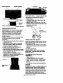
Owner's Manual _
I:R-nFTSM.gll
o
17.0 HP
ELECTRIC STAR'T
42" MOWER
6"SPEED TRANS_XLUE-
LAWN TRAG TOR
Modet N_.
917.270711
•
•
•
•
Safety
Assembly
Operation
Maintenance
• Repair Parts
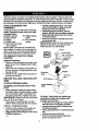
CAUTION:
Read and follow all
Safety Rules and Instructions
before operating this equipment.
For answers to your questions
about this product,Call:
1-800-659-5917
Sears Craftsman Help Une
5 am - 5 pm, Mon- Sat
Sears, Roebuck and Co., Hoffman Estates, IL 60179
Nlaintenance......................................... 18
Varrar_-_ ..... -. ...............................
. ........ 2
_afety Rules ...........................................
2 : Service and Adjustments ...................... 22
_rodObTS p°eCifiC_ti'on_ '...._ ......'...:.. :...::....5
Storage ................................................. 28
ssembly,.. ...... ,.-,-,-,---.,---..------,--.-...... 8
Troubleshooting.................................... 29
)peration ..............................................
12
Repair Parts ......................................... 32
Ylaintenance Schedule.._i_,',i_ .............. 18
Parts Ordering ..:.................... Back Cover
.IMITF_,__TVyO YEAR WARRANTY
ON CRAFTSMAN
RIDII_G EQUIPMENT
"ortwo (2) years from the date of I_umh_se, if this Craftsman Riding Equipment is main=_ined, lubricated and tunedup according to the instructions in the owner's manual,
;ears will repair or replace, free of charge, any parts found to be defective in material or
,orkmanship.
"his Warra._n_ty_do__s
not cover:.
Expendable items which become worn during normal use, such as blades, spark
plugs, air cleaners, belts, etc.
Tire replacement or repair caused by punctures from outside objects, such as nails,
thorns, stumps, or glass.
Repairs necessary because of operator abuse, negligence, improper storage or accident or the failure to maintain the equipment according to the instructions contained in
the owner's manual.
Ridingequipment
used for commercial
.IMITED 90 DAY WARRANTY
or rental purposes.
ON BATTERY
"or ninety (90) days from date of purchase, if any battery included with this riding equip
lent proves defective in material or workmanship and our testing determines the bat.=rywill not hold a charge, Sears will replace the battery at no charge. In-home warranty
;ervice on your Craftsman riding equipment is available at no charge for 30 days from
lie date of purchase. Please contact your nearest service center. After 30 days from the
ateof purchase, warranty service is available by taking your Craftsman riding equiplent to your nearest Sears Service Center. (In-home warranty service will still be availtble after 30 days from the date of purchase but a standard trip charge will apply). This
varranty applies only while this product is in the United States. This Warranty gives you
i;pecific legal rights, and you may also have other dghts which may vary from state to
;tate.
_ears, Roebuck and Co., D/817 WA, Hoffman Estates, IL 60179
._ENERAL OPERATION
• Never.carry passengers.
• Do not mow in reverse unless absolutely necessary. Always look down and
behind before and while backing.
• Be aware of the mower discharge direction and do not point it at anyone. Do
not operate the mower without either
the entire grass catcher or the guard in
place.
• Slow down before tuming.
• Never leave a running machine unattended. Always tum off blades, s_eet
parking brake, stop engine, and remove
keys before dismounting.
Read, understand, and follow all instructions in the manual and on the machine
before starting.
Only allow responsible adults, who are
familiar with the instructions, to operate
the machine.
. Clear the area of objects such as rocks,
toys, wire, etc., which could be picked
up and_wn
by the blade.
Be _ure _e area is clear of other people
befom_owmg.
Stop machine if anyone
enters the area.
2
• Do notby to stabilize the machine by
putting your foot on the ground.
• Do not use grass catcher on steep
slopes.
CHILDREN •
•Tum
off blades when not mowing.
• Stol_engine before removing grass
catcher or unclogging chute.
• Mow only in daylight or good artificial
lighL
• Do not operate the machine while under
the influence of alcohol or drugs.
• Watch for traffic when operating near or
crossing roadways.
• Use extra care when loading or unloading.the machine into a trm'le_or truck.
SLOPE OPERATION
Tragic accidents can occur if the operator
is not alert to the presence of children.
Children are often attracted to the
•machine and the mowing activity. Never
assume that children will remain where
you last saw them.
-- Keep children out of the mowing area
• and under the watchful care of another
'_
Slopes are a major factor related to lossof-control and tipover accidents, which
can result in severe injury or death. All
sl.opes require extra caution. If you cannot
back up th-e-_s-l_peo_ iT you feel uneasy on
it, do not mow it.
DO:
responsible adulL
• Be alert and turn machine off if children
enter the area.
• Before and when backing, look behind
and down for small children. •
• Never carry children. They may fall off
and be seriously injured or interfere with
safe machine operation.
• Never allow children to operate the
machine.
• Mow up and down slopes, not across.
• Remove obstacles such as rocks, tree
limbs, etc.
• Watch for holes, ruts, or bumps. Uneven
terrain_could overtum the machine. Tall
• Use extra care when approaching blind
comers, shrubs, trees, or other objects
that may obscure vision.
SERVICE
grass Can hide obstacles.
• Use slow speed. Choose a low gear so
that you will not have to stop or shift
while on the slope.
• Follow the manufacturer's recommen-
• Useextra cam in handling gasoline and
other fuels. They are flammable and
vapors am explosive.
Use only an approved container.
Never remove gas cap or add fuel
with the engine running. Allow engine to cool before refueling. DO not
smoke.
Never rehJel the machine indoors.
Never store the machine or fuel
dations forwheel weights or counterweights to improve stability.
• Use extra care with grass catchers or
other attachments. These can change
the stability of the machine.
• Keep all movement on the slopes slow
and gradual. Do not make sudden
changes in speed or direction.
• Avoid starting or stopping on a slope. If
--tires lose traction, disengage the blades
container inside where there is an
open flame,such as a water heater.
• Never run a machine inside a closed
and proceed slowly strai.ght down the
slope.
area.
• Keep nuts and belts, especially blade
attachment bolts, tight and keep equipment in good condition.
• Never tamper with safety devices.
Check their proper operation regularly.
• Keep machine free of grass, leaves, or
other debris build-up. Clean oH or fuel
spillage. Allow machine to cool before
•" stodng,.
• Stop and.inspect the.equipment
H you
strike an object. Repair, ifnecessary,
before restading,
DO NOT:
• Do nottum on slopes unless necessary,
and then, tum slowly and gradually
downhill, if possible.
• Do not mow near drop-offs, ditches, or
embankments. The mower could suddenly turn over if a wheel is over the
edge of a cliff or ditch, or if an edge
caves in.
• Do not mow on:wet grass, Reduced
traet'N_'ffP_uld-_use sfiding.
• "
3"
"
• Never make acljustments orrepairs with
engine running.
• Grass catcher components are subject
to wear, damage, and deterioration,
which could expose moving pads or
allow objects to be thrown. Frequently
check components and replace with
• Be sure the area is clear of other people
be_f_or_e__owj.n.g,
Stop machine if anyone
enters the area.
* Never carry passengers.
• Do not mow in reverse unless absolutely necessary.Always look down and
behind before and while backing.
• Never carry children. They may fall off
and be seriously injured or interfere with
-safemachine operation.
• Keep children out of the mowing area
and under the watchful care of another
• responsible adult.
• Be alert and tum machine off if children
enter the area.
• Before and when backing, look behind
and down for small children.
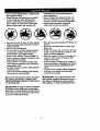
_Look for this symbol to point out important safety precautions. It means CAUTIONI!! BECOME AWAREI!! YOUR SAFETY !S INVOLVED.
_CAUTION:
In order to prevent accidentatst-arting when setting up, transporting,
adjusting or making repairs always disconnect spark plug wire and place wire where
it cannot contact spark plug.
manufacturer's recommended parts,
when necessary.
Mower blades are sharp and can cut.
Wrap the blade(s) or wear gloves, and
use extra caution when servicingthem.
Check brake operation frequently. _
Adjust and service as required.
• Mow up and down slopes (15° Max), not
across.
• Remove obstacles such•as rocks, tree
limbs, etc.
• Watch for holes, ruts, or bumps. Uneven
terrain could overtum the machine. Tall
grass can hide obstacles.
• Use slow speed. Choose a low gear so
that you will not have to stop or shift
while on the slope.
• Avoid starting or stopping on a slope. If
tires lose traction, disengage the blades
and proceed slowly straight down the
slope.
• Do not tum on slopes unless necessary,
and then, tum slowly and gradually
downhill, if possible.
_WARNING:
The engine exhaust from
this product contains chemicals known to
the State of Caiifomia to cause cancer,
birth defects, or other reproductive harm.
ShoukJ
you-e ,rk=nce
anyproUem
you..
.R0.u..or
spE=RcA!n .s
....
cannot easily remedy, please cor_tact your "
nearest Sears Authorized Service Center.
We have competent, well-trained technk
clans and the proper tools to service or
repair this tractor.
Please read and retain this manual. The
125 GALLONS
UNLEADED
REGULAR
CAPACITY
-
SAE 30 (above320F)
SAE 5W-30
OIL TYPE
instructions will enable you to assemble
and maintain your tractor properly. Always
observe the "SAFETY RULES'.
(below 32°F)
OIL CAPACITY:
3;0 PINTS
SPARK PLUG:
Champion RC12YC
MAINTENANCE AGREEMENT
INTAKE: .003"-.005"
A Sears Maintenance Agreement is available on this product. Contact your nearest
Sears store for details.
(GAP: .030")
EXHAUST: .005"-.007"
GROUND
(MPH):
SPEED
FORWARD:,
•
I sT
2 ND
3 RD
................
4 TM
5TM
6TM
REVERSE:
PRESSURE:
....
SYSTEM:
FRONT:
REAR:
CUSTOMER
1.2
1.5
2.4
3.5
4.8
5.4
1.5
• Read and observe the safety rules.
• Follow a regular schedule in maintaining, caring for and using your tractor.
• Follow the instructions under =Maintenance" and "Storage" sections of this
owner's r.-'mual.
_,WARNIhG:
This tractor is equipped
with an internal combustion engine and
should not be used on or near any unimproved forest-covered, brush-covered or
grass-covered land unless the engine's
exhaust system is equipped with a spark
arrester meeting applicable local or state
laws ('_ any). If a spark an'ester is used, it
should be maintained in effective working
order by the operator.
In the state of Califomia the above is
14 PSI
10 PSI
3 AMPS BATTERY
5 AMPS HEADLIGHTS
AMP/HR:
25
MIN. CCA:
190
CASE SIZE: UIR
BLADE BOLT
RESPONSIBILITIES
27-35 FT. LBS.
required by law (Section 4442 of the
California Public Resources Code). Other
states may have similar laws. Federal
laws apply on federal lands. A spark
arrester for the muffler is available through
your nearest Sears Authorized Service
Center (See REPAIR PARTS section of
this manual).
CONGRATULATIONS on your purchase
of a Cra_an
Tractor. It has been
designed, engineered and manufactured .
to give you the.best possible depondab, ity
ar;d performance.
5
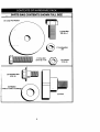
PARTS BAG CONTENTS SHOWN FULL SIZE
_'_'-
lr
(1) Large Flat Washer:
(1) Hex Bolt
3/8-16 x I
(1) Lockwasher
3/8
(1) Hex Bolt
5/16-18x 1-1/4
@
(1) Locknut
5/16-18
(1) Shoulder Bolt
5/16-18
(1) Washer
.17/32 x 1-3/16 x 12
Q
(1) Knob
6
" -
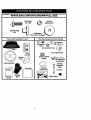
PARTS BAG CONTENTS,-SHOWN:FULL
_
SIZE •
(2) Screws
/_
(2) Lock
#10 x 5/8
_t_
Washem #10
(2) Weld Nuts
#10
(2) Washem
_/16 x 3/4 x 16 Gauge
Parts packet separately in carton
Parts Bag contents not shown full size
_]ER.
(_
(2) Washers
(2) Shoulder _
3/8 x 7/8 x 14
Bolts
(2) Centerlock Nuts (A' _f))
Seat
(2) .Gauge -Wheels
Cassette
Steering Wheel
Adapter
Mulcher /?/_
Video
i_"
(_
-
•Steermg Wheel
_'_'_ I
I
I-,
(2) Latch Hook
Assemblies-:.
Steering "
Extension
Steedng
Wheel Insert
Boot
Shaft
(2) Keys
Slope Sheet
i
7
Yot_rnew-tractorhasbeen assembledat the factorywithexceptionof thosepartsleft
unassembledfor shippingpurposes.Toensuresafe andproperoperationof yourtractor
all parts andhardwareyou assemblemust be tightened securely. Use the correct tools
as necessary
TOOLS
to insure proper tightness. Review the video cassette before you begin.
REQUIRED
FOR
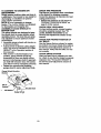
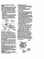
• Position steering wheel so cross bars
are horizontal (left to right) and slide
inside boot and onto adapter.
• Assemble large flat washer, 3/8 lock
washer, 3/8 hex bolt and tighten securely.
• Snap steering wheel insert into center
of steering wheel.
• Remove protective materials from tractor hood and grill.
IMPORTANT: Check for and remove any
staples in skid that may puncture tires
where tractor is to roll off skid.
ASSEMBLY
A socket wrench set will make assembly
easier. Standard wrench sizes you need
are listed below.
(1_)9/16" wrench
(1) Phillips Screw
ddver
(2) 1/2" wrench
(1)Tirepressure
(1) Pliers
(1) Utility knife
gauge
(1) 3/4" wrench socket
drive.mchet .......
When right or left hand is mentioned in
this manual, it means, from your point of
view, when you are in the operating position (seated behind the steering wheel).
TO REMOVE
TRACTOR
Insert
Lockwasher
3/8 He_
Bolt
FROM
CARTON
Large Flat
UNPAeK-CARTON
• Remove all accessible loose parts and
parts boxes from shipping carton (See
page 6),
• Cut, from top to bottom, along lines on
all four comers of shipping carton, and
lay panels flat.
• Check for any additional loose parts or
boxes and remove.
BEFORE ROLLING TRACTOR
SKID
ATTACH STEERING WHEEL
ASSEMBLE
_
EXTENSION
SHAFT
Stee__iill
r
Wheel
OFF
AND
BOQT_
• Slide extension shaft onto lower steering shaft. Align mounting holes in extension and lower shafts and install 5/16
hex bolt and Iocknut. Tighten securely.
IMPORTANT:
Tighten bolt and nut securely to 18-22 ft. Ibs. torque.
• • Place tabs of steering boot over tab
slots in dash and push down to secure.
INSTALL
STEERING
TOROLL TRACTOR OFF SKID (See
Operation section for location and
function of controls)
• Press lift lever plunger and raise attachment lift lever to its highest position.
• Release parking brake by depressing
clutch/brake pedal.
• Place gearshift lever in neutral (N) position.
• Roll tractor forward off skid.
WHEEL
• Position front wheels of the tractor so
they are pointing straight forward.
• Slide steering'wheel adapter onto steer--in g'_raft -e_tension.
• Remove banding holding discharge
guard up against tractor.
8
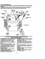
,tOW TO SET UP YOUR TRACTOR
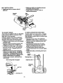
CHECK BATTERY
Lift seat pan to _
position and open.
Seat Pan
Shoulder
Bolt
batteyJ>ox_door.
• If this battery is put into service after
month and year •indicated on label (label
located between terminals) charge bat-,
tery for minimum of one hour at 6-10
amps. (See "BATTERY": in MAINTERat Washer
NANCE section of this manual for charg- AdjustmentKnob
ing instructions).
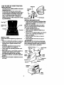
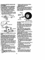
INSTALL MULCHER PLATE
• Install tWOlatchh0oks tOimUlcher plate
Seat Pan
using screw, washer, I_ Washer, and
weld nut as shown.
NOTE,"
Pre-assembla Weldnut to latch
Battery
Box
,Label
hook by inseding weld nut fromthe top
Door
with hook pointing down.
• Tighten hardware securely.
-Terminal_
• Raise and hold deflector shield in upright position.
• Place front of mulcher plate over front of
mower de;.,_opening and slide into
place, as shown.
• Hook front latch into hole on front of
mower deck.
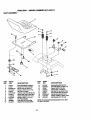
INSTALL SEAT
•
Hook rear latch into hole on back of
Adjust seat-beforetightening adjustment
mower deck.
knob.
• Remove cardboard packing on seat pan. 4_CAUTION: Do not remove discharge
guard from mower; Raise and hold guard
• Place seat on seat pan and assemble
•when attaching mulcher plate•and allow it
shoulder bolt. _ghten shoulder bolt
to rest onplate while in operation.
•i
securely.
• Assemble adjustment knob andfiat
Weld Nut
Hook Points
washer loosely. Do not tighten.
The Top .,_
• Lower seat into operating position and
Down
sit on seat:
Lock
Weld Washer
• Slide seat until a comfodable position is
reached which allows you .topress
Screw
clutch/brake pedal all the way down.
Latch
• (_et off seat without moving its adjusted
position. •
- .
....
_Ralse's_at and tighten adjustment knob
..
.
..
•
Weld Nut
securely.
Washer
[-Lock, Washer
Washer
Mulcher
Screw.
Deflector
Shiekl
Latch
Hooks
•
9
CHECK TIRE PRESSURE .
The tires on your tractor were overinflated
at the factory for shipping purposes.
Correct tire pressure is important for best
cutting performance.
• Reduce tire pressure to PS! shown in
=PRODUCT SPECIFICATIONS" on
page 5 of this manual.
TO CONVERT TO BAGGING OR
DISCHARGING
_Simply remove mulcher plate and store in
a safe-place. Your mower is now ready for
discharging or installation of optional
grass catcher accessory.
NOTE: It is not necessary to change
blades. The mulcher blades are designed
for discharging and bagging also.
_.SSEMBLE GAUGE WHEELS TO •
MOWER DECK
The gauge wheels are designed to keep
the mower deck in proper position When
opemting-rnower. Be sure they are properly adjusted to ensure optimum mower
performance.
• Assemble gauge wheels with tractor on
a flat level surface.
_, Adjust-mewer-to_desired cutting height
(See "TO ADJUST MOWER CUTTING
HEIGHT" in the Operation section of
this manual).
• With mower in desired height of cut
position, gauge wheels should be
assembled so they are slightly off the
ground. Install gauge wheel in appropriate holewithshoulder bolt, 318 washer,
and 3/8-16 Iocknut and tighten securely.
• Repeat for opposite side installing
gauge wheel in same adjustment hole.
CHECK
DECK
LEVELNESS
For best Cutting results, mower housing
should be properly leveled. See "TO
LEVEL MOWER HOUSING" in the
Service and Adjustments section of this
manual.
•
CHECK
FOR PROPER
POSITION
OF
ALL BELTS
See the figures that are shown for replacing motion and mower blade drive belts in
the Service and Adjustments section of
this manual. Verify that the belts are routed correctly.
CHECK BRAKE SYSTEM
After you leam how to operate your tractor, check to see that the brake is properly
adjusted. See -TO ADJUST BRAKE" in
the Service and Adjustments section of
this manual.
Gauge Wheel MounUng
Bracket
3/8-16
Locknut
-..°
10
/CHECKLBT
PLEASE REVIEW'rFIE
CHECKEIS'P.
,/
FOLLOWING
All assembly instructions have been
completed.
.,_
_ -.
/
No remaining loose parts in carton.
,/
Battery is properly prepared and
charged. (Minimum I hour at 6 amps).
,/
Seat is adjusted comfortably and
tightened securely.
,/
All tires are propedy inflated. (For
shipping purposes, the tires were
• o_-rinftated at the factory). "
,/ Be sure ilrmwer deck is properly leveled
side-to-side/front-to-rear
for best
,/
,/
cutting results. (Tires must be properly
inflatedfor ___veling).
Check mower and drive belts. Be sure
they are routed propedy around pulleys
and inside all belt keepers.
Check wiring. See that all connections
are still secure and wires are propedy
clamped.
WHILE LEARNING HOW TO USE YOUR
TRACTOR," PA_" EXTRA A'I-I'ENTION TO
THE FOLLOWING
IMPORTANT ITEMS:
4'
/
,/
Engine oil is at proper level.
Fuel tank is filled with fresh, clean,
regular unleaded gasoline.
Become familiar with all controls - their
location and function. Operate them
"before you start the engine.
4' Be sure brake system is in safe
operating condition.
11
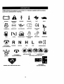
Th6_sesymbols may appear on your tractor or in literature supplied with the product.
Learn and understand their meaning.
,=
t
BATrERY
CAUTIONOR
WARNING
REVERSE
FORWARD
FAST
FUEL
CHOKE
MOWER HEIGHT
PARKING BRAKE
LOCKED
UNLOCKED
N H
ATTACHMENT
CLUTCH ENGAGED
IGNITION
REVERSE
NEUTRAL
ATTACHMENT
CLUTCH DISENGAGED
HIGH
KEEP AREA CLEAR
SLOW
MOWER UFT
L
c®) I
LOW
PARKING BRAKE
SLOPE HAZARDS
(SEE SAFETY RULES SECTION)
FREE WHEEL
DANGER, KEEP HANDS AND FEET AWAY
(Automatic Models only)
12
;NOW YOUR TRACTOR
IEAD THIS OWNER'S MANUAL AND,SAFETY RULES BEFORE OPERATING YouR
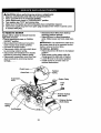
"RAC'r_R
"ompa_ethe illustrations with your tractor to familiarize yourself with the locations of
arious controls and adjustments. Save this manual for futurereference.
Ammeter
Clutch Lever
Ught
Switch
Ignition
s
Throttle/Choke
Control
J
s
Lift Lever
%
Plunger
_.u_ral_
Pedal
\
,
©
Attachment Lift
Lever
Parking Brake
Height
Adjustment
Knob
Gearshift
Lever
Our tractors conform to the safety standards of the American
National Standards Institute.
ATTACHMENT cLUTCH _LEVER: Used
to engage the mower blades, or other
attachments mounted to your tractor.
LIGHT SWITCH: Tums the headlights on
and off.
THROTTLE/CHOKE CONTROL: Used
for starting and controlling engine speed.
CLUTCH/BRAKE PEDAL: Used for
declutching and braking the tractor and
starting the engine.
PARKING BRAKE: Locks clutch/brake
pedal into the brake position,
HEI_JUS_rMENT
KNOB: Used to
adjusHtm, mower cutting height.
GEARSHIFT LEVER: Selects the speed
and direction of tractor.
ATTACHMENT
LIFT LEVER:
Used to
raise, lower, and adjust the mower deck or
other attachments mounted to your tractor.
LIFT LEVER PLUNGER:
Used to release
attachment lift lever when changing its
position.
IGNmON SWITCH:
stopping the engine.
AMMETER:
Indicates battery charging
(+) or discharging (-).
13
Used for starting and
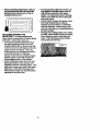
The operation of any tractor can result in foreign objects thrown into the
eyes, which can result in severe eye damage. Always wear safety glasses or eye shields while operating your tractor or performing any adjustments or repairs. We recommend a wide vision safety mask over spectacles, or standard safety glasses.
HOW TO USE YOUR TRACTOR
Your tractor is equipped with an operator
presence sensing switch, When engine
is running, any attempt by the operator to
leave the seatwithout first setting the
parkingbrake will shut off the engine.
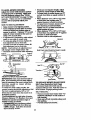
TO SETPARKING
BRAKE
IMPORTANT: Leaving the ignition switch
in any position other than "OFF" will cause
the battery to be discharged (dead).
NOTE: Under certain conditions when
tractor is standing idle with the engine running, hot engine exhaust gases may
cause "browning" of grass. To eliminate
this possibility, always stop engine when
pping tractor on grass areas.
CAUTION:
Always stop tractor completely, as described above, before leaving
the operator's position; to empty grass
catcher, etc.
• J)epress clutch/brake pedal into full
-=BRAKE"position and hold.
• Placeparking
brake lever inENGAGED" position and ielease pressure from clutch/brake pedal. Pedal
should remain in "BRAKE" position.
Make-sure-parkingbrake will holdtractor secure.
Throttle/Choke
Control lever
Attachment Clutch Lever
"Engaged" Position
_
"Disengaged"
ClutCh/Brake _
_/Position
TO MOVE FORWARD AND BACKWARD
The direction and speed of movement is
controlled by the gearshift lever.
• Start tractor with clutch/brake pedal
depressed and gearshift lever in neutral
(N) position.
• Move gearshift lever to desired position.
Peda-I-"D_d_- -_-_:_./Parking
Brake
Position
L "',_"
\V_
"Engaged"
_hifl
"Disengaged" Adjustment "PositionLever
Position
Knob
• Slowly release clutch/brake pedal to
start movement.
STOPPING
MOWER BLADES -
IMPORTANT: Bdng tractor to a complete
stop before shifting or changing gears.
Failure to do so will shorten the useful life
• To stop mower blades, move attachment clutch lever to DISENGAGED"
position.
GROUND DRIVE-
of your transaxle.
TO ADJUST MOWER
•
To stop ground ddve_ depress
clutch/Drake pedal into full "BRAKE"
7
position •
--.
• Move gearshift lever to neutral (N) positio-n.
ENGINE
-
CUTTING
HEIGHT
The cutting heiOht iS controlled by turning
the height adjustment knob in desired
direction.
• Turn knob clockwise (G) to raise cutting
height.
• Turn knob counterclockwise (O)to
lower cutting height.
The cutting height range is approximately
1-1/2" to 4". The heights are measured
from the ground to the blade tip with the
engine not running. These heights are approximate and may vary depending upon
soil conditions, height of grass and types
of grass being mowed.
_.
• Move throttle control to slow position.
NOTE-" Failure to move throttle control to
slow position and allowing engine to idle
before, stopping may cause engine to
"backfire'.
• Tum ignition key to "OFF" position and
remove key. Always remove key when
--le'_
tremor to prevent unauthodzed
• Never use choke to stop engine.
THROTTLE CONTROL
Always operate engine at full throttle.
• Operating engine at less than full throttle reduces the battery charging rate.
• Full throttle offers the best bagging and
mower performance.
14
• The average lawn should be cut to
approximately 2-t/2 inches dudng the
cooLseason and to over3 inches during
hot_nonths. For healthier andbetter
looking lawns, mow often and after
moderate growth.
• For best cutting performance, grass
over 6 inches in height should be
- mowed twice. Make the first cut relatively high; the second to desired
height.
TO OPERATE MOWER
Your tractor is equipped with an operator
pres_ce-sensing switch. Any attempt by
the operator to leave the seat with the
engine running and the attachment clutch
engaged will shut off the engine.
Select desired height of cut.
• Lowe_-r_o_-w_'li attachment lift control.
• Start mower blades by engaging attachment clutch control.
• TO STOP MOWER BLADES - disen•gage attachment clutch control.
Attachment Clutch
Lever "Fngaged___
Position
Attachment Lift Lever
High Position
_'(
=Disengag_____Low
.
ACAuTION:
Do not operate the mower
without either the entire grass catcher, on
wnowers.so equipped, or:the discharge
guard in place.
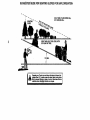
TO OPERATE ON HILLS:
_kCAUTION: Do not drive up or down
"hills with slopes greater than 15° and do
not drive across any-slope_A slope guide
at the back of your manual isprovided for
your use.
:"
• Choose:the slowest speed before starting up or down hills. "
• ••Avoidstopping or changing speed on
i _."hillS,...i • " _.":..: ....
" _
"
_ve_loslower
n isa ut
position.:
• Move gearshift lever to 1st gear. Be
sure you have allowed room for tractor
to roll slightly as you: restart movemenL
• To restart movement, slowly release
parking brake and clutch/brake pedal.
• Make all tums slowly.
TO TRANSPORT
• Raise attachment lift to highest position
with attachment lift control.
• When pushing or towing your tractor, be
sure gearshift lever is in neutial (N)
position.
• Do not push or tow tractor at more than
five (5) MPH.
.'.
NOTE: To protect hood from damage
when transporting your tractor on •a truck
or a trailer, be sure hood is closed and
secured to tractor. Use an appropriate
means of tying hood to tractor (rope, cord,
etc.).
BEFORE STARTING THE ENGINE
CHECK ENGINE OIL LEVEL
• The engine in your tractor has been
shipped, from the factory, already filled
with summer weight oil.
• Check engine oil with tractor on level
ground.
• Remove oil fill cap/diPStick and wipe
clean,reinsert the dipstick and screw
cap tight, wait for a few seconds,
remove and read oil level: If.necessary,
add oil until "FULL" mark on dipstick is
reached. Do not overfill.
• For cold weather operation you should
change oil for easier starting (See =OIL
VISCOSITY CHART" in the Mainten•ance section of this manual).
• To change engine oil, see the Maintenance section in this manual.
ADD GASOLINE
"
• Fill fuel tank. Use fresh, dean, regular
unleaded gasoline with a minimum of
87 .octane. (Use of leaded gasoline will
increase carbon and lead oxide
deposits and reduce valve life). Do not
mix oil with gasoline- Purchase fuel in
quantities that can be used within 30
.days to assure fuel freshness.
IMPORTANT: When operating in temperatures below 32"F(0°C), use fresh, clean
.
winter grade gasoline to help insure good
coM weather starling; _
necessary,
j_usl_clutch/Drake pedal quickly to brake
position and engage parking broke.
15
_WARNING:
ExPerience
indicates that
alcohol blended fuels (called gasohol or
usi'ng-eth_mol or methanol) can attract
moisture which leads to separation and
formation of acids during storage. Acidic
gas can damage the fuel system of an
engine while in storage. To avoid engine
problems, the fuel system should be emptied before storage of 30 days or longer.
Drain the gas tank, start the engine and let
it run until the fuel lines and carburetor are
empty. Use fresh fuel next season. See
Storage Instructions for additional information. Never use engine or carburetor
cleaner products in the fuel tank or permanct amage may occur.
AUTION: Fill to bottom of gas tank
filler nec_De
not overfill. Wipe off any
spilled oil or fuel. Do not store, spill or use
gasoline near an open flame.
TO START ENGINE
When starting the engine for the first time
or if the engine has run out of fuel, it will
take extra cranking time to move fuel from
the ta__nktothe engine.
• Sit on seat in operating position,
depress clutch/brake pedal and set
parking brake.
• Place gear shift lever in neutral (N) position.
• Move attachment clutch to =DISENGAGED" position.
• Move throttle control to choke position.
NOTE: Before Starting, read the warm
and cold starting procedures below.
• Insert key into ignition and turn key
clockwise to "START" position and
release key as soon as engine starts.
Do not run starter continuously for more
thaR fifteen seconds per minute. If the
engine does not stad after several
attempts, move throttle control to fast
position, wait a few minutes and try
again. If engine still does not start,
move the throttle control back to the
choke position and retry.
WARM
WEATHER
STARTING
(50 ° F and
above)
• When engine starts, move the throttle
control to the fast position.
• The attachments and ground drive can
now be used. If the engine does not
-- a_L_t tl'_load, restart the engine and
_..._i!ow _to warm up for one minute using
the choke as described above.
COLDWEATHER
STARTING ( 50°F AND
BELOW)
• When engine starts, allow engine to run
with the throttle control in the choke
position until the engine runs roughly,
then move throttle control to fast position. This may require an engine warmup period from several seconds to several minutes, depending on the temperature.
• The attachments can also be used during the engine warm-up period.
NOTE: If at a high altitude (above 3000
feet) or in cold temperatures (below 32 F)
the carburetor fuel mixture may need to be
adjusted for best engine performance.
See "TO ADJUST CARBURETOR"
in the
Service and Adjustments section of this
manual.
MOWING TIPS
• Tire chains cannot be used when the
mower housing isattached to tractor.
• Mower should be properly leveled for
best mowing performance. See "TO
LEVEL MOWER HOUSING" in the
Service and Adjustments section of this
manual.
° The left hand side of mower should be
used for trimming.
• Drive so that clippings are discharged
onto the area that has been cut. Have
the cut area to the right of the machine.
This will result in a more even distribution of clippings and more uniformcutting.
• When mowing large areas, start by tuming to the dght so that clippings will discharge away from shrubs, fences, driveways, etc. After one or two rounds,
mow in the-opposite direction making
left hand tums untilfinished
° If grass is extremely tall, it should be
mowed twice to reduce load and possible fire hazard from dried clippings.
Make first cut relatively high; the second
to the desired heighL
• Do not mow grass when it is wet. Wet
grass will plug mowerand leave undesirable clumps. Allowgrass to dry
before mowing.
• Always operate engine at full throttle
when mowing to assure better mowing
performance and proper.discharge of
material. Regulate ground speed by selecting a low enough geaHegive the
mower the best cutting performance as
well as the quality of cut desired.
16
* When operating:attachments,
-i- ,speed
• .For..l:_e_result,%adjustlhe mower cut-.
ting.heigMso _lhe
mower cuts off;
onlytbe.top one-third of the grass
.
blades. For extremely heavy mulching,
reduce your width of cut on each pass
and mow slowly.
• Certain types of grass and grass conditions may require thatan area be
mulched a second time to completely
hide the clippings..When doing a second cut, mow across or perpendicular tothe first cutpath.
• Change your cuttingpattem from week
- to weel_. Mow .northto south one week
then change to east to west the next
week. This will help prevent matting
and graining of the lawn.
select a
thatwm,s ttheterra
._ and give best pedormance
tacit.. _ent beingused.
of.the at-
.(
MULCHING MOWING TIPS
IMPORTANT: Forbest performance,
keep mower housing free of built-up grass
and trash. Clean after each use.
• The special •mulching blade will recut
. the grass clippings many times and
reduc6_-mTn _i_6so that as they fall
onto the lawn they willdisperse into the
grass and not be noticed. Also, the
mulched grass will biodegrade quickly
to provide nutrients for the lawn.
Always mulch with yourhighest engine
(blade) speed as this will provide the
best rgcu_ng_action of the blades.
• Avoid cutting your lawn when it is wet.
Wet grass tends to form clumps and
interferes with the mulching action. The
best time to mow your lawn is the early
afternoon. At this time the grass has
dried andthe newly Cut area wgl not be
exposed to the direct sun.
17
CUSTOMER RESPONSIBILITIES
AS YOU COMPLETE
REGULAR
SERVICE
ICE DATES
T
Check Tire Pressure
Check Operator
Presence
Interlock Systems
-.
R
Check for Loo_ Fasteners
A
Sharpan/ReplaceMowerBlade=
T
0
Lubr_a.on
Chat
c_._€_
Batteryt.qMDI
I/
R
clean Battery and Tennirmls/Rectmrge
V'
Check Transaxle Cooling
V'
Adjust
Blade
Adjust
Motion
Check
BE
V e
Ik_
._
.
V'
t/,
•
V'
V',
"
Belt(s) Tension
! Ks
Drive Belt(s) Tension
Engine Oil Level
Muffler/Spark
V'
t/,
ik_s
V p
V'
Clean
Clean AW
Air miter
Screen "
Inspect
N
I_
and
VP=
V'=
Attester
i
V'
Rep_
o. RIt,.-(._._)
Clean.Englne
CoolingFins
v_=
Replace
Spark
_
Replace
Air Filter Paper
Plug
Cartridge
V p
I_z
I_i-e_l_F._l_lYilter
I.
2.
3.
Change moro often when operating under 8 heavy load or In high mmblent tmnPeratUreL
Sefylr,,e more olten when operating kt dl_y _ dusty €ondttlom=.
It equipped wtlh oil _ter, change ol ever_ SO haum.
•
GENERAL
RECOMMENDATIONS
The warranty on this tractor does not cover
items that have been subjected to operator
abuse or negligence. To receive full value
frbm the warranty, operator must maintain
tractor as instructed in this manual. Some
adjustments will need to be made periodically to properly maintain your tractor.
All adjustments in the Service and
Adjustments section of this manual should
be checked at least once each season.
• Once-a year you should replace the
spark plug, clean or replace air filter, and
check blades and belts for wear. A new
spark plug and clean air filter assure
proper air-fuel mixture and help your
engine run better.and last longer.
S - If equipped wl81 =dJtmtable system.
S - Not rm_'Fdred If equipped with rrmbltemmce-froe batteqf7 -_
Imnt axle pl_t bolt to 3S It.-Ibe. maxlmwn.
LUBRICATION
CHART
O
Zerk
Spindle
Zerk
Front
Wheel
• Front Wheel
Bearing Zerk
Bearing
Zerk
• Engine
O Attachment
Clutch
Pivot(s)
: O GearI
I
shift
' Pivots
0 SAE 30 or 10w30 Motor OIL
@ General Purpose Grease
O Refer to Maintenance "Engine"Section
BEFORE EACH USE
• Check engine oil level.
• Check brake operation.
• Check tire pressure.
• Check operator presence and interlock
systems for proper operation.
• C_or
Io_se fasteners.
IMPORTANT: Do not oil or grease the
pivot points which have special nylon bearings. Viscous lubricants will attract dust
and dirt that will shorten the life of the selflubricating bearings. If you feel they must
be lubricated; use only a dry, powdered
graphite type lubricant sparingly.
18
TRACTOR
• TIghtan bolt securely (27-,35 Ft. Lbs.
torque).
Always observe safety rules when performing,any maintenance.
IMPORTANT: Blade bolt is Grade 8 heattreated.
BRAKEOPERATION
If tractor requires more than six (6) feet
stopping distance at high speed in highest
gear, then brake must be adjusted. (See
"TO ADJUST BRAKE" in the Service and
Adjustments section of this manual).
TIRES
Trailing
• Maintain proper air pressure in all tires
(See PRODUCT SPECIFICATIONS" '
on page 3 of this manual)..
• "Keep tires free of.gasoline, oil, Orinsect
control-chemicals Whichcan harm rub-
Lock Washer_._.
Center
Hole
MandrelAssembly
Rat
Star
<_<'Hex Bolt (Grade 8)*
*A Grade 8 heat treated boltcan be
identified by six lines on the bolt head.
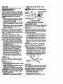
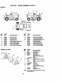
TO SHARPEN BLADE
ber,
NOTE: We do not recommend sharpening•
blade, but if you do, be sure the blade is
balanced.
Care should be taken to keep the blade
balanced. An unbalancedblade will cause
excessive vibration and eventual damage
to mower and engine.
• The blade can be sharpened with a file
or on a grindingwheel. Do notattempt
to sharpen while it is on the mower,
• To check blade balance, you will need a
5/8" diameter steel bolt, pin, or a cone
balancer, (When using a cone balancer,
follow the instructionssupplied with bal-
• Avoid stumps, stones, deep ruts, sharp
objects and other hazards that may
cause tire damage.
NOTE: :r_seaHire- punctures and prevent
flat tires due to slow leaks, tire sealant
may be purchased from your local parts
dealer. Tire sealant also prevents tire dry
rot and corrosion.
OPERATOR PRESENCE SYSTEM
Be sure that operator presence and interlock systems are working properly. If your
tractordoes-not function as described
below, repair the problem immediately.
• The engine should not start unless_the
clutch!brake pedal is fullydepressed
and attachment clutch control is in the
disengaged position.
• When the engine is running;any attempt by the operator to leave the
-seat without first setting the parking
brake should shut off the engine.
• When the engine is runningand the
attachment clutch is engaged, any
attempt by the operator to leave the
seat should shut off the engine.
•-The attachment clutch should never.
operate unless the operator is in the
seat.--:
-;
BLADE CARE
For best results mower I_lades must be
kept sharp. Replace bent or damaged
- blades.
BLADE REMOVAL
• Raise mower to I_[ghestposition to allow
- access to blades.
• Remove hex bolt, lock washer and flat
washer securing blade.
• Instal!.new orresharpened bladewith
• trailing _up
towards:deck as shown.
IMPOFrrAN'ri To ensureproper assembly,
Centerl:_oleih:blade must•align with star
on-mmt!ltel as=embly.:
• Re_mble'
hex bolt, lockwasher and
--tla_ash-_r in exact Orderas shown.
•
Blade
ancer).
NOTE: Do not use a nail.for balancing
blade. The lobes of the center hole may
appear to be centered, butare not.
• Slide blade onto an unthreaded portion
of the steel bolt or pin and hold the bolt
or pin parallel with the ground. If blade
is balanced, it should remain in a hod- .
zontal position. If either end of the blade
moves downward, sharpen theheavy
end untilthe blade isbaianced_
CenterHole
/
/
Blade
5/8" Bolt
or Pin
BATTERY
Your tractor has a battery charging system
which is sufficientfor normaluse.• Howew
er, periodic charging of the .battery.withan
automotive charger will extend its:life. . ::.
• . KeeP battery andterminals clean..:.:- .....
• Keep.battery bol_,tighL : .
•- Keep small.vent hOlesopen..
• "Recharge at 6-10 amperes fo_L1_hour.: "
o
19
NOTE::l'h_odginal
equipment
TO CHANGE ENGINE OIL
Determine temperature range expected
before oil change. All oil must meet API
service classificationSF, SG or SH.
• Be sure tractor is on level surface.
• Oil will drain more freely when warm.
• Catch oi!in a sui_ble container.
• •Remove oil fill cap/dipstick, Be careful
not to allow dirtto enter the engine
when changing oil.
• Remove drain plug.
• •After oil has drained completely, replace
oil drain plug and tighten securely.
• Refill engine with oil through oil fill dipstick tube. Pour slowly.Do not overfill.
For approximate capacity see "PRODUCT SPECIFICATIONS =Ton page _ of
this manual.
• Use gauge on oil fill cap/dipstick for
checking level. Be sure dipstick cap is
tightened securely for accurate reading.
Keep oil at =FULL" line on dipstick.
battery on
your tractor is maintenance free. Do not
attg_mptto open Or remove caps or covers.
Addihg or checking level of electrolyte is
not necessary.
TO CLEAN BATTERY AND TERMINALS
Corrosion and dirt on the battery and terminals can cause the battery to "leak"
power.
• Open battery box door.
• DisconnectBLACK battery cable first
then RED battery cable and remove
battery from tractor.
• Rinse the battery with plain water and
-_,4ry_ - •
•
Clean terminals and battery cable ends
withwire brush untilbright.
• Coat terminals with grease or petroleum
jelly.
• Remstall,,ba=ttery(See =REPLACING
BA'I-I'ERY in the SERVICE AND
ADJUSTMENTS section of this
manual).
V-BELTS
Check V-belts for deteriorationand wear
after 100 hours of operation and replace if
necessary. The belts are not adjustable.
Replace._be!ts_
ifthey begin to slip from
wear.
TRANSAXLE
COOLING
Keep transaxle free from build-up of dirt
and chaff which can restrict cooling.
ENGINE
LUBRICATION
Only use high quality detergent oil rated
with API service classification SF, SG or
-SH. Select the oil's SAE viscosity grade
• according to your expected operating temperature.
Oil Drain
AIR FILTER
..
Your engine will not runproperly using a
dirty ajrfllter. Clean the foam pre-cleaner
after every 25 hours of operation or every
season. Service paper cartridge every 100
hours of operation or every season,
whichever occurs first.
Service air cleaner more often under dusty"
conditions.
• Remove knob(s) and cover.
TO SERVICE PRE-CLEANER
• Slide foam pre..cleaner off cartridge.
• Wash it in liquid detergent and water.
• Squeeze it dry in a clean cloth.
SAE VLSCOSITYGRADES
roll
.
"rEM_I_llJRE
,o.
RANGE _T_ATED
8EFI_E.
,.
NEXT OK.¢.,lt_C_
• Saturate it in engine oil. Wrap it in clean,
NOTE: Although multi:Viscosityoils
(5W30, 10W30 etc.) improve starting in
cold weather, these multi-viscosityoils will
result in increased oil consumption when
used above 32°F. "Checkyour engine oil
level more frequently to avoid possible
engine damage from running low on oil.
Change the oil after every 25 hours of
operation or at least once a year if the
tractor is not•used for 25 hOursin one
year,
Check thecrankcase oil level before starti_ng-tlNi_ngil_eand after each eight (8)
hours of operation. Tighten oil fill cap/dip:stlL"IL_ect_'ely each time you check the oil
level.
absorbent cloth and squeeze to remove
excess oil.
• If very dirty or damaged, replace precleaner.
• Reinstall pre-cleaner over cartridge.
• Reinstallcover and secure with knob(s).
TO SERVICE CARTRIDGE
• Remove cartridge nut.
.
• Carefully remove cartridge to prevent
debris from entering carburetor.Clean
base Carefully to prevent debris from
entering carburetor.
• Clean cartridge by tapping gently on flat
surface. If very dirty or damaged,
replace cartridge.
20
• Relns
MUFFLER-
.cover and secure _
knob(s).
IMPORTANT:
Petroleum solvents, such as
kerosene, are not to be used to clean the
cartridge. They may cause deterioration of
the cartridge. Do not oil cartridge. Do not
use pressurized
air to clean or dry cartridge.
Inspect and replace corroded muffler+and
spark armster ('d equipped) as it could create a fire hazard and/or damage.
SPARK PLUGS
Cover
Knob
Cover
......
Cartridge
_Base
CLEANAIR
SCREEN
Air screen must be kept free of dirt and
chaff to prevent engine damage from overheating. Clean with a wire brush or compressed air to remove dirt and stubbom
dried gum fibers.
ENGINECOOUNG
FINS
Remove any dust, dirt or oil from engine
cooling fins to prevent enginedamage
from overheating.
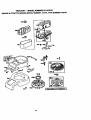
• Remove
screws from blower housing
and lift housing and dipstick tube
assembly off engine.
• Cover oil fill opening to prevent entry of
dirL
• Use compressed air or stiff bdstle brush
to thoroughly clean engine cooling fins.
• To reassemble, reverse above proce,
dure.
"_Scr__
-Dip
.Blower ,Housing
-
.".
Replace spark plugs at the beginning of
each mowing season
Orrafter
every
100
hours of operation, whichever occurs r,'st.
Spark plug type and gap setting are
shown in "PRODUCT SPECIFICAT|ONS"
on page 5 of this manual,
IN-LINE FUEL RLTER
- -The fuel filter should be replaced once
each season. If fuel filter becomes
Cartridge
Nut
Pre-Clean
Foam
er#_
•
dogged, obstructing fuel flow to carburetor, replacement is required.
• With engine cool, remove filter and plug
fuel line sections.
• Place new fuel filter in position in fuel
line with arrow pointing towards carburetor.
• Be sure there are no fuel line leaks and
clam.
CLEANING
• Clean engine, battery, seat, finish, etc.
of all foreign matter.
• Keep finished surfaces and wheels free
of all gasoline, oil, etc.
• Protect painted surfaces with automotive type wax.
We do not recommend using a garden
hose to clean your tractor unless the ele¢-. trical system, muffler, air filter and carburetor are covered to keep water out. Water
in engine can result in a shortened engine
life.
Scrffws!_
mr screen
Assemb /
|-.
Plug
21
.m.
,ACABTION: Before performing any service or adjustments:
• [}epress clutch/brake pedal fully and set parking brake.
• Place gearshift lever in neutral (N) position.
• Place attachment clutch in "DISENGAGED" position.
• Turn ignition key'OFF" and removekey.
• Make sure the blades and all movingparts have completely stopped.
Disconnect spark plug wire from spark plug and place wire where it cannot come
in contact with plug.
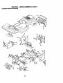
TO REMOVE MOWER
Mower will be easier to remove from the
right sid8 of tractor.
• Place attachment clutch in "DISENGAGED" position.
• Move attachment lift lever forward to
lower mower to its lowest position.
• Roll b-el_o-ff:_-ng3ri_
pulley.
• Disconnect clutch rod from clutch lever
by removing retainer spring.
• Disconnect anti-swaybar from chassis
bracket by removing retainer spring.
• Disconnect suspension arms from rear
deck brackets by removing retainer
spri_ngs_
..........
• Disconnect front links from deck by
removing retainer springs.
• Raise liftlever to raise suspension
arms. Slide mower out from under tractor.
IMPORTANT: If an attachment other than
the mower deck is to be mounted on the
tractor, remove the front links.
TO INSTALL MOWER ,
• Raise attachment lift lever to its highest
position.
• Slide mower under tractor with discharge guard to right side of tractor.
• Lower lift lever to its lowest position.
• Install mower in reverse order of
removal instructions.
Clutch
Retainer
Clutch Rod
Spring
Suspension
Arms
Engine Pulley
Front
Unk
\
Retainer Springs
(Both Sides)
Springs
(Both Sides)
Retainer
Spdng
22
TO LEVEL MOWER HOUSING
Adju_the
mower while b'a_or, is parked
on level ground or driveway. Make sure
tires _re pro_)erly inflated (See "PRODUCT SPECIFICATIONS"
on page 5 of this
manual).
If tires are over or unclednflated, you will not properly adjust your
mower.
SIDE-TO-SIDE
ADJUSTMENT
• Raise mower to its highest position.
'
• At the midpoint of both sides of mower,
measure heigM from bottom edge of.
mower to ground.
Distance ,A" on both
si_=s ()f mower should be the same or
within 1/4" of each other.
• If adjustment is necessary, make adjustment on one side of mower only.
-* To raise_oneside o.f mower, tighten lift
link adjustment nut on that side.
• To lower one side of mower, loosen lift
link adjustment nut on that side.
NOTE:
Each full tum of adjustment nut
will change mower height about 1/8".
• Recheck measurements after adjusting.
Bottom
of CudS--
•
,
....
•
!_ _
• ff links am not equal in length, adjust
one link to same lengthas other link.
• To lower front of mower Iooasn nut "E"
on both front links an equal number of
turns.
• When distance "[7' is 1/8" to 1/2" lower
at front than rear, tighten nuts "IF"
against trunnion on both front links.
• To raise front of mower, loosen nut "F"
from trunnion on both front links.
"lighten nut =E" on both front links an
equalnumberof turns.
When distance "17' is 1/8" to 1/2" lower
at front than rear, tighten nut "F= against
trunnion on both front links.
• Recheck side-to-side adjustment.
Mandrel
Both Front Links Should be Equal in Length
Bottom
of Curl
• rr't-lj
Su pen io,',
Nut'E'
Nut,F"
A,m
"
)"
Trunnion
FR "ONT.. TO-BACK ADJUSTMENT
IMPORTANT:
.=side.
ment
front
level
Deck must be level side-to _
!f_the following front-to-back adjustis necessary, be sure to adjust both
links equally so m_wer will stay
side-to-side.
-To obtain the best cutting results, the
mower housing should be adjusted so that
the front is approximhtely 1/8" to 1/2"
lower than the rear when the mower is in
its highestposition.
Check adjustment on right side of tractor.
Measure distance "D = directly in front and
behind the mandrel at bottom edge of
.. mowet:housir)g ._."_:shoWni:i.-- : " "
'. _fqC!_lli_[Iganynecessary
adjuSt. n_rits, ch_
that both front linksare
-ec]1:1_in length. Both links should be
approximately
10-3/8".
Front Unks
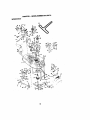
TO REPLACE
MOWER
BLADE
DRIVE
BELT (See Illustration Next Page)
The mower blade drive belt may be
replaced without tools. Park the tractor on
level surface. Engage parking brake.
BELT REMOVAL
-
• Remove mower fromtractor (See "TO
REMOVE MOWER" in this section of
this manual).
• Work belt off both mandrel pu!leys"and
idler Pulleys. ::: . .i : _,;:...' :-. :.:. ,
• Pu!lbeit a_yfr.O.m_:-m0.
we:c: -...
23
BELT INSTALLATION • Install new belt in reverse order of
rer_ovat:.
* Make sure belt is in all pulley grooves
and inside all belt guides.
• Install mower in reverse order of
"
removal instructions.
.
Idler
Pulleys
Mandrel
Pulley
Mandrel
Pulley
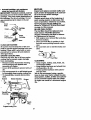
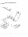
TO ADJUST BRAKE
Your tractor is equipped with an adjustable
brake system which is mounted on the
right side of the transaxle.
If tractor requires more than six (6) feet
stoppTn_oTst_h_:eat highspeed in highest gear, then brake must be adjusted.
• Depress clutch/brake pedal and engage
parking brake.
• Measure distance between brake operating arm and hut "A" on brake rod.
• If distance is other than 1-1/2", loosen
- jam nut and tum nut "A" untildistance
becomes 1-1/2". Retightenjam nut
against nut "A".
• Road test tractor for proper stopping
distance as stated above. Readjust if
- necessary. If stopping distance is still
greater than six (6) feet in highest gear,
• . further maintenance is necessary.
Contact your nearest authorized service center.
--.
TO REPLACE MOTION DRIVE BELT
Park the tractor on level surface. Engage
parking brake. For assistance, there is a
belt installation guide decal on bottom side
of left footrest.
• Remove mower (See "TO REMOVE
MOWER" in this section of this manual.)
• Remove belt from stationary idler and
clutching idler.
• Pull belt slack toward rear of tractor.
Remove belt upwards from tmnsaxle
pulley by deflecting belt keepers.
• Pull belt toward front of tractor and
remove downwards from around engine
pulley.
• Install new belt by reversing above procedure.
Clutching Idl
W'dh Parking Brake "Engaged"
Sta_onary ,d,er_
Nut "A"
Jam Nut
Arm
24
_f
"
• Replace washers and snap retain'rag
rRANSAXLE SHIFTER UNKAGEAND
_DJUSTMENT
The transaxle should _ in neutral when
the ge ar-shift.Jever is in the neutral (N).
:lock gate) position. The adjustment is
)reset at the factory;,however, if adjust1lent is needed, proceed as follows:
• Make sure tmnsaxle is inneutral (N).
• Loosen two Iocknuts on tie rod.
•-Tum center rod until gearshift lever falls
into neutral lock gate on fender console.
• Tighten Iocknuts securely.
ringsecurelyin axle groove.
• Replaceaxlecover.
NOTE: To seal tire punctures and prevent
flat tires due to slow leaks; tire sealant
may be purchased from your local pads
dealer. Tire sealant also prevents tire dry
rot and corrosion.
Washers
• Ret=n_ng
R_
Neutral Lock
Gate
!
Axle Cover
Locknuts
TO START ENGINE
BATTERY
THAT HAS A WEAK
&CAUTION:
Lead-acid batteries generate explosive gases. Keep sparks, flame
and smoking materials away from batteries. Always wear eye protection when
around batteries.
Tie
If your battery is too weak to start the
engine, it should be recharged. (See
"BA'I-I:ERY" in the MAINTENANCE
sec-
Transaxle
TO ADJUST
MENT
"_Square
Key
(Rear Wheel Only)
STEERING
WHEEL
tion of this manual).
If=jumper cables', are used for emergency
starting, follow this procedure:
JLIMPORTANT:
Your tractor Is equiped
with a 12 volt negative grounded system.
The other vehical must also be a 12 volt
AUGN-
If steering wheel crossbars are not horizontal (left to right) when wheelsare positioned straight forward, remove steering
wheel and reassemble per instructions in
negative grounded system. Do not use
your tractor battery to start other vehicais.
adjustable on your tractor.-.!f damage has
occurred to affect the front wheel toe-in or
TO ATI'ACHJUMPER
CABLES • Connect each end of the RED cableto
the POSITIVE (+)terminal of each battery, taking care not to short against
chassis.
• Connect one end of the BLACK cable to
-camber; contact your nearest authorized
service center.
TO REMOVE WHEEl: FOR REPAIRS
the NEGATIVE (-) terminal of fully
charged battery.
• Connect the other end of the BLACK
• Block up axle securely.
• Remove axle cover, retaining ring and
washers to allow wheel removal (rear
wheel contains a square key - Do not
cable to good CHASSIS GROUND,
away from fuel tank and battery.
the-Assemblysectionof this manual.
JERONT WHEEL TOE-IN/CAMBER
The front wheel toe-in and camber are not
lose).
TO REMOVE
CABLES,
REVERSE
ORDER=:
:
• BLACK cable first from chassis and
"
• Repair tire and reassemble.• On.. _..ee_
only:.,align grooves_ in
rear Wheel hub and axle. Insert square
key.,':_
-_"
then from the fully charged battery.
• RED cablelast from both batteries.
25
Positive
Term/.hal
Hex Bolt
Positive (Red) Cable
Negative (Black) Cable
TO REP=LACE HEADLIGHT
BULB
• Raise hood.
• Pull bulb holder out of the hole in the
Charged
Battery
Positive Terminal
Negative Terminal
backside of the grill.
• Replace bulb in holder and push bulb
holder securely back intothe hole in the
backside of the grill.
• Close hood.
REPLACING •BATTERY
ACAUTION:
Do not short battery terminals by allowing a wrench or any other
object to contact both terminals at the
same time. •Before connecting battery,
remove metal bracelets, wristwatch
bands,rings,etc.
Positive terminal must be connected first
to prevent-sparking from accidental
grounding.
'
• Lift seat pan to raised position and open
battery box door.
• Disconnect BLACK batterycable first
then RED battery cable and carefully
remove battery from tractor.
•.-Install new battery with terminals in
same position as old battery.
• First connect RED battery cable to positive (+) terminal with hex bolt and nut as
shown. Tighten securely.
ConnectBLACK
grounding cable to
negative (-) terminal with remaining hex
boR and nut. Tighter_securely.
Close battery box door.
Seat Pan
Battery Box
Door
INTERLOCKS
AND RELAYS
Loose or damaged wiring may cause your
tractor to run poorly, stoprunning, or prevent it from starting.
• Check wiring. See electrical wiring diagram in the Repair Parts section of this
manual.
TO REPLACE
FUSE
Replace with 30 amp automotive-type
plug-in fuse. The fuse holder is located
behind the dash.
TO REMOVE HOOD AND GRILL
ASSEMBLY
--;• Raise hood.
• Unsnap headlight wire connector.
• Stand in front of tractor. Grasp hood at
sides, tilt toward engine and lift off of
tractor.
• To replace, reverse above procedures.
ENGINE
Maintenance, repair, or replacement of the
emission control devices and systems,
which are being done at the customers
expense, may be performed by any •nonroad engine repair establishment or individual. Warranty repairs must be performed by an authorized engine manufac26 turer's service outlet.
TOADJUST .'II'IROTTLECONTROL
CABLE
--.
PREMMINARY
The tl_o_ttle _controlhas been preset at the
factory and adjustment should not be necessary. Check adjustment as descn'bed
below before loosening cable, if adjustment is necessary, proceed as follows:
• With engine not running, move throttle
- control lever from slow to cho!_e posi1ion. Slowly move lever from'choke to
adjusted properly (see above).
FINAL SETTING
Governor
Control Plate
\
Holes "A"
TO ADJUST
Clamp
Screw
:
Throttle
Cable
CARBURETOR
NOTE: The carburetor on this engine is
low emission. It is equipped with an idle
fuel adjusting needle)with a limiter cap,
which allows some adjustment within the
limits allowed by the cap. Do not attempt
to remove the limiter cap. The limiter cap
cannot be removed without breaking the
adjusting needle.
_l'he carburetor has been'preset at the factory and adjustment should not be necessary. However, minor adj;_rstment may be
required to compensate for differences in
-fuel,'temperature,
altitude or load. If the
-
• Start engine and allow to warm for five
minutes. Make final adjustments with
engine running and shift/motion control
lever in neutral (14)position.
• Move throttle control lever to slow position. With finger, rotate and hold throttle
lever against idle speed screw. Turn idle
speed screw to attain 1750 RPM.
• While still holding throttle lever against
idle speed screw, turn idle mixture valve
full travel clockwise then counterclock-
Check that holes "A" in governor control
lever and hole in govemor plate line-up.
ff _oles_A " are not aligned, loosen
clamp screw and move throttle cable
until holes are alii)ned. Tighten clamp
screw securely.
___Go_vemor_
....
Control Lever
wise until engine runs rough. Turn valve
to a point midway between those two
positions. Release throttle lever.
ACCELERATION
TEST • Move throttle control lever from slow to
fast position. If engine hesitates or dies,
turn idle mixture valve out (counterclockwise) 1/8 tum. Repeat test and
continue to adjust, if necessary, until
engine accelerates smoothly.
High speed stop is factory adjusted; Do
not adjust---d_,mage may resulL
IMPORTANT:
Never tamper with the
engine governor, which is factory set for
proper enginespeed,
overspeeding the
engine above the factory high speed setting can be dangerous, if you think the
engine<3ovemed high speed needs
adjusting, contact.your nearest authorized
serviceconter, which has proper equip.ment to make any necessary adjusbn, ents.
Idle Speed Screw'-
carburetor does need adjustment, proceed
as follows:
In general, turning idle mixture valve in
!cloc kw_ise) decreases the supply of fuel to
.,me engine giving a leaner fuel/air mixture.
. Tuming the idle mixture valve out "
.
- (cou_.."terclockwisa)"mcreases the Supply of
luel.tothe engine givi.nga richerfuel/air
rnixture_.
-.-----_-
IM.P.P.P.P.P.P.P.P.P_TAI_r:
Damage to the needle valve
afid _ sea_ in carburetor may result if
screw is turned in too tight.
-
bled to the carburetor when making carburetor adjustments.
• Be sure the throttle control cable is
astpos, .
•
SETTING
o. Air oleaner assembly must be essem-
Valve W'_h.
_r
27
Tl_rottle
Lever
Immediately prepare your tractor for storage at the end of the season or if the tractor will not be used for 30 days or more.
,ACAI.rFION: Never store the tractorwith
gasoline in the tank inside a building
where fumes may reach an open flame or
spark. Allow the engine to cool before storing in any enclosure.
TRACTOR
Remove mower from tractor for winter
st6r'ag_ This will allow you to clean it thoroughly. Remove all dirt, grease, leaves,
etc. Store in a clean, dry area.
• Clean entire tractor (See "CLEANING" in
the Maintenance section of this manual).
• Inspect a_cTre_ie.cebelts, if necessary
(See belt replacement instructionsin the
Service and Adjustments section of this
manual).
• Lubricate as shown in the Maintenance
section of this manual.
• Be sure that all nuts, bolts and screws
am_sec_eLyfastened. Inspect moving
parts for damage, breakage and wear.
Replace if necessary.
• Touch up all rusted or chipped paint surfaces; sand lightlybefore painting.
fuels (called gasohol or using ethanol or
methanol) can attract moisture which
leadsto separation and formation of acids
during storage. Acidic gas can damage the
fuel system of an engine while in storage.
• Drain the fuel tank.
• Start the engine and let it run untilthe
fuel lines and carburetor are empty.
• Never use engine or carburetorcleaner
products in the fuel tank or permanent
damage may occur.
• Use fresh fuel next season.
NOTE: Fuel stabilizer is an acceptable
altemative in minimizing the formation of
fuel gum deposits during storage. Add stabilizer to gasoline in fuel tank or storage
container. Always follow the mix ratio
found on stabilizer container. Run engine
at least 10 minutes after adding stabilizer
to allow the stabilizer to reach the carburetor. Do not drain the gas tank and carburetor if using fuel stabilizer.
ENGINE OIL
Drain oil (with engine warm) and replace
with clean engine oil. (See "ENGINE" in
the Maintenance section of this manual).
CYLINDER(S)
• Remove spark plug(s).
• Pour one ounce of oil through spark
plug hole(s) into cylinder(s).
•Tum
ignition key to "START" position for
a few seconds to distribute oil.
BATTERY
• Fully charge the battery for storage.
•- After a' period of time in storage, battery
may require recharging.
.. To help prevent corrosion and power
leakage during long periods of storage,
battery cables should be disconnected
and battery cleaned thoroughly (see "TO
CLEAN BATTERY AND TERMINALS" in
the Maintenance section of this manual).
• After cleaning, leave cables disconnected and place cables where they cannot
come in contact with battery terminals.
• If battery is removed from tractor for
storage, do not store battery directly on
concrete or damp surfaces.
• Replace with new spark plug(s).
OTHER -.
• Do not store gasoline from one season
to another.
• Replace your-gasoline can if it starts to
rust. Rust and/or dirt in your gasoline
will cause problems.
• If possible, store your tractor indoors
and cover itto give protection from dust
and dirt.
• Cover your tractor with a suitable protective cover that does not retain moisture. DOnot use plastic. Plastic cannot
breathe, which allows condensation to
form and cause your tractor to rust.
IMPORTANT: Never cover tractor while
engine and exhaust areas are still warm.
ENGINE
FUEL SYSTEM
•
IMPORTANT:
It is important to prevent
gum deposits from forming in essential fuel
system parts suqh as carburetor, fuel filter,
fuel _,
or tank during storage. Also,
expe1_e
ir_icates that alcohol blended
28
ROUBLESHOOTING CHART
t-CAUSE
CORRE¢;¥iON
• Out of fuel
-• Engine not =CHOKED"
• Fill fuel tank.
• See "TO START
properly.
• Engineflooded.
Operation section.
• Wait several minutes before
•
•
•
•
•
•
•
•
Bad spark plug
Dirty air filter.
Dirty fuel filter.
Waterin fuel
ENGINE" in
attempting to starL
Replace spark plug.
Clean/replace airfilter.
Replace fuel filter.
Drain fuel tank and carburetor, refill tank with fresh
gasoline and replace fuel filter.
• Engine valves out of
adjustment.
• Check all wiring.
• See "To Adjust Carburetor"
in Service and Adjustments
section.
• Contact an authorized service center.
•
•
•
•
•
•
•
•
•
• Loose or damaged wiring.
• Carburetor out of adjustment.
Hard to start
Clean/replace air filter.
Replace spark plug.
Recharge or replace battery.
Replace fuel filter.
Drain fuel tank and refill with
fresh gasoline.
• Check all wiring.
, See "To Adjust Carburetor"
in Service and Adjustments
section.
• Contact an authorized service center.
Dirty air filter.
Bad spark plug.
Weak or dead battery.
Dirty fuel filter.
Stale or dirty fuel
• Loose or damaged wiring.
• Carburetor out of adjustment.
* Engine valves out of
adjustment.
Engine will not turn
over
• Clutch/brake pedalnot
depressed.
• Attachment clutchis
engaged.
• Weak or dead battery.
• Depress clutch/brake
• DiSengage
clutch.
damagedwiring.
-
t-." Faulty ignition switch.
• Faulty
solenoidor:starter.
"
• Faulty operator presence
switch(es).
/,
•
Engine clicksbut
will not.,Slji
_
- .
.
-
.,
,
• Weak Ordead battery.
•Corroded
battery terminals.
29
attachment
• :ReCharge or replace battery.
• Replace fuse. "
• Clean battery terminals.
• Blown fuse.
• Corroded battery terminals.
• Looseor
pedal.
• Check all wiring.
• Check/replace ignition
switch.
:
,; Check/replace solenoid or
starter.
,; Contact an authorized service center.
"..
:..
_• Recharge or replace battery.
• Clean battery terminals.
TROUBLESHOOTING
PROBLEM
CHART
.-
"
CORRECTION
CAUSE
Engiae_clicksbut
will not start (con
t'd)
• Loose or damaged wiring.
• Faulty solenoid or starter.
• Check all wiring.
• Check/replace solenoid or
starter.
Loss Ofpower
• Cutting too much
grass/too fast.
• Throttle in =CHOKE"
• Set in "Higher Cut" position/reduce speed.
• Adjust throttle control.
tieR.
posi-
!.
• Build-up of grass, leaves
and trash under mower.
• Dirty air filter.
• Low oil level/didy oil.
• Faulty spark plug.
• Dirty fuel filter.
• Stale or dirty fuel.
Water in fuel.
• Spark plug wire loose.
• Dirty engine air
screen/fins.
' Dirty/clogged muffler.
• Loose or damaged wiring.
• Carburetor out of adjustment.
• Engine valves out of
adjustment.
Excessive vibration
• Wom, bent or loose blade.
• Bent blade mandrel.
• Loose/damaged part(s).
"Engine cOntinues to
run when operator
leaves seat with
=attachment
engaged
* _Faulty operator-safety
g.resencecontrol system.
clutch
Poor cut - uneven
• Wom, bentor
t
loose blade.
Mower deck not level.
• Buildup of grass, leaves,
and trash under mower.
• Bent blade mandrel.
3O
• Clean Underside of mower
housing.
• Clean/replace air filter.
• Check oil level/change oil.
• Clean and regap or change
spark plug.
• Replace fuel filter.
• Drain fuel tank and refill with
fresh gasoline.
• Drain fuel tank and carburetor, refill tank with fresh gasoline and replace fuel filter.
• Connect and tighten spark
plug wire.
• Clean engine air screen/fins.
• Clean/replace muffler.
• Check all wiring.
• See "ToAdjust Carburetor" in
Service and Adjustments
section.
• Contact an authorized service center.
• Replace blade. Tighten blade
boll
• Replace blade mandrel.
• Tighten loose part(s).
Replace damaged pads.
Check widng, switches and
connections. If not
corrected, contact an authorized service center..
• Replace blade. Tighten blade
boll
• Level mower deck.
• Clean underside of mower
housing.
• Replace blade mandrel;
TROUBLESHOOTINGCHART
PROBLEM
CAUSE
CORRECTION
• Cloggedmowerdeckvent
holesfrombuildupof
grass,leaves,andtrash
Poo'r _cut --uneven
(cont'd)
• Clean around mandrels to
open vent holes.
around mandrels.
Vlower blades wii
not rotate
Poor-grass
di-
• Obstruction in clutch
mechanism.
• Remove obstruction.
• Worn/damaged
drive belt.
• Replace mower drive belt.
mower
• Frozen idler pulley.
• Frozen blade mandrel.
• Replace idler pulley.
• Replace blade mandrel.
• Engine speed too slow.
• Place throttle control in
charge
• Travel speed too fast.
• Wet grass.
• Mower deck not level.
• Low/uneven tire air pressure.
• Wom, bent or loose blade.•
• Buildup of grass, leaves•
and trash under mower.
• Mower drive belt wom.
• Blades improperly
installed.
"FAST" position.
• Shift to slower speed.
• Allow grass to dry before
mowing.
• Level mower deck.
• Check tires for proper air
pressure.
• Replace/sharpen
blade.
Tighten blade belt.
•
• •Clean underside of mower
•
•
• Improper blades used.
•
• Clogged mower deck vent
holes from buildup of
•grass, leaves, and trash
•
housing.
Replace mower drive belL•
Reinstall blades ` sharp edge
down.
Replace with bladeslisted in •
this manual.
•:
Clean around mandrels tO
open vent holes.
around mandrels.
Headlight(s) not
working (if so
equipped)
-_ ....
', Switch is "OFF'.
• Turn switch'oN,.
•- Bulb(s) bumed out.
•, Faulty light switch.
-_. Loose or damaged wiring.
• Blown fuse.
• Replace bu!b(s).•
• Check/replace lightswitch.
• Checkwiringandconnectkx_
• Replace fuse.
ii.
Battery will not
charge
_;
• Bad battery Cell(s).
• Poor cable connections.
• Faulty regulator (if so
• Replace battery.
• Check/clean all connections.
• Replace regulator.
equipped).
Engine. =bac!dires"
when tuming;
engine 'OFF"
• Faulty alternator.
• Replace altemator..
, Engine throttle control not
• setat "SLOW"
positionfor 30 seconds
before stopping engine.
• Move throttle control to
31
.SLOW.
_
a !a,ow••
to idlefor 30 secondsbefom
stopping engine..
.
:-.
'
TRACTOR
- - MODEL
NUMBER
917.270711
ELECTRICAL
r
i
I
i
I
i
!
i
.i
7O
26
28
32
TRACTOR
.- MODEL
NUMBER
917.270711
ELECTRICAL
KEY
PART
NO.
NO.
1
2
8
16
19
2O
21
22
24
25
26
27
28
_29
30
31
32
33
40
41
42
43
44
45
52
70
NOTE:
144925
74760412
156417
153664
STD551125
733504O0
147430
4152J
4799J
146147
108824X
73510400
4207J
121305X
140301
124211X
141226
I O9310X
156442
71110408
131563
145673
7364O4OO
121433X
141940
140422
DESCRIPTION
Battery12 VOLT 25 AMP
BoltHex Hd 1/4-20unc x 3/4
Case Battery
Switch, InterlockPush-In
Washer Lock 114
Nut Jam Hex 114-20Unc
Harness AsmLightw14152j
Bob Light#1156
Cable Battery 6 Ga 11"red
Cable Battery 6 Ga w/16 wire red
Fuse 30 AMP AutoGreen
Nut, Keps Hex 1/4-20 UNC
Cable Ground6 Ga 12" black
Switch PlungerNc Gray
Switch Ign 4 Pos
Nut Ignition
Cover Sw Key BIk I 25 Text SLT
Key Ign MoldedCraftsman
Harness Ign Man CI Am Hm 97
Bolt BIk. Fin Hex 1/4-20 Unc x 1/2
Cover TerminalRed
Solenoid
Nut Keps BIkHex 1/4-20 Unc
Ammeter Rectangular6 Amp
ProtectionWire Loop
Harness EngineB&S 14 OHV
Allcomponentdimenslonsgive in U.S. inches
1 inch = 25.4 mm
TRACTOR
- - MODEL NUMBER
917_70711
CHASSIS AND ENCLOSURES
28
12
S
53
31
55
14
54
141•
TRACTOR
- - MODEL" NUMBER,
917.270711
CHASSIS AND ENCLOSURES
KEY
PART
NO.
NO.
1
2
3
4
5
9
10
11
12
13
14
17-18
25
26
28
29
3O
31
37
"38
39
51
52
53
54
55
57
60
54
74
114
115
116
140
142
143
144
145
--
NOTE:
160392
140356
17490612
19131216
155272
161917X013
STD533710
155927
145660
155936
17490608
144983X558
126938X
19131312
STD541437
145198X558
155217X599
151287X558
139976
17490508
139886
139887
73800400
19091416
145201
161464
145202
STD522507
72140606
154798
STD541437
158112
17490620
19131614
158418
156095
154966
154207
156524
5479J
DESCRIPTION
ChasdsAssembly
Drawbar
Screw, Thd. Roll. 3/8-16 x 3/4
Washer 13/32 x 3/4 x 16 Gauge
BumperHood/Dash
Dash
Bolt, Carriage 3/8-16 x 3/4
Panel, Dash, LH.
Clip "13nnerman
Grille P/L
Panel, Dash, R.H.
ScrewThdrol 3/8-16 x 1/2
Hood Assembly
BumperHood
Washer 13/32 x 13/16 x 12 Gauge
Nut
Grille w/Clips MS-558
Lens, Grille
Fend/Rrest Pnt STLT N HLD 558
Bracket,Fender Support
ScrewThdrol 5/16-18 x 1/2
PivotBracketAssembly,LH.
PivotBracketAssembly,R.H.
Nut Lockw/Insert 114-20 UNC
Washer 9/32 x 7/8 x 16 Ga.
BracketGrillePIckoff LH
Screw Hex Wshd 8-18 x 7/8
BracketGrille PlckoffRH
Bolt, Rn Hex 114-20UNC x .75
BoltRdhd Sqnk 3/8-16 UNC x 3/4
Dash Lower STLT
Nut Crownlock 3/8016 UNC
Keeper Belt Rear Lh SU P93O
Screw Thdrol3/8-16 x 1-114Tytt
Washer 13/32 x I x 14 Ga.
BracketSuspensionFront
Plate ReinforcementSTLT
Bracket
Swaybar
Chassis
BracketPnt FootrestSTLT
Rod PivotChassis/Fkx)d
Plug, Button
All componentdimensionsgive in U.S. inches
1 inch = 25.4 mm
-
35
TRACTOR
GROUND
. - MODEL
NUMBER
917.270711
DRIVE
26
1
27
36
TRACTOR
- . MODEL
NUMBER
917.270711
GROUND DRIVE
KEY
NO.
PART
NO.
DESCRIPTION
........
2
3
4
5
6
8
10
11
13
14
- 18
19
21
22
24
25
26
27
28
29
30
31
32
34
35
36
37
38.
39
40
41
42
47
48
49
50
_51
52
53
55
Transaxle (See Breakdown)
Peedess 206-508B
146682
Spring, Return, Brake
123666X
Pulley,Transaxle
12000028
Ring, Retainer
121520X
Strap,Torque
17490512
Screw,Thd., Roll. 5/16-18 x 3/4
_ :154792
Rod ShifterFender STLT
STD561210 - Pin, Cotter
105701X
Washer, Shift Plate
74550412
Bolt 1/4-28 UNF W/Patch Gr. 8
STD551125
Washer
ST_D5_23!10_ ,.BQ_.FInHex 3/8-16 UNC x 1.
Gr 5
STD541437
Nut
106933X
Knob
130804
Rod, Brake
STD541237
Nut
106888X
Spring,Brake Rod
STD551037
Washer
STD561210
Pin
145204
Rod, ParkingBrake
_1-2-42_X ..... Cap, ParkingBrake, Red
130807
Bracket,Transaxle
127275X
Keeper, Belt,LH.
STD523107
Bolt
155071
Shaft Assembly,Foot Pedal
120163X
Bearing, Nylon
STD551062
Washer
STD571810
Roll Pin
123674X
Pulley, Idler,Flat
STD523727
Bolt
4470J
Spacer, Split .395 x .59
154777
Keeper, Belt, Idler Fool-Proof
19131312
Washer 13/32 x 13/16 x 12 Ga.
127763
Pulley,Idler,V-Groove, Plastic
154407
Bellcrank Clutch Gmd Dry Stl
123205X
Retainer,Belt
STD523715
Bolt
STD641437
NutCrown Lock 3/8-16 UNC
STD541431
NutCrown Lock 5/16-18 UNC
105710X
105709X
Link,Clutch
Spring,Clutch Retum
KEY
NO.
56
57
56
59
61
62
63
64
65
56
70
72
74
75
76
77
78
79
80
81
82
83
84
85
86
87
88
89
90
96
112
113
116
145
148
149
150
151
NOTE:
PART
NO.
DESCRIPTION
Bolt Fin Hex 3/6-16 x 1-1/4
V-Belt, Ground Drive
Keeper, Belt, R.H.
Keeper, Belt, Center Span
Screw, Thd., RolL 3/8-16x 3/4
Cover, Pedal
Pulley,Engine
Bolt, Hex Head, Rn.
7116-20 x 4 Grade 5
Washer
STD551143
Keeper, Belt, Engine, Fool154778
Proof
GuIde, Mower Drive Belt, R.H.
134683
Washer 13/32 x 1-1/4 x 12 Ga.
19132012
137057
Spacer, Axle
Washer 25/32 x 1-1/4 x 16 Ga.
121749X
STD581075
E-Ring
123583X
Key, Square 2.0 x .1645/.1865
Washer 25/32 x 1-5/8 x 16
121748X
Gauge
Key Woodruff#9 3/16 x 3/4
2228M
Arm, Shilt
145090
Shaft Assembly
161082
Spdng, Torsion
123782X
Washer 17/32 x 3/4 x 16 Ga.
19171216
Tie Rod
145643
Nut, Nylock
150360
Bushing
157480
Washer
19212016
E-Ring
12000008
Console, Shift, STLT
158391
Nut, Self-Thding,Wsh Hd 1/4
124346X
Retainer Spring1"
4497H
Washer 9/32 x 3/4 x 10 Gauge
19091210
Strap Torque I.h Lt
121520X
Bolt Rdhd Sqneck 3/6-16 x 1.25
72110610
Bolt, Hex Flghd 5/16-18 Gr. 5
74490540
Spacer
159103
Spacer Retainer PM Mower
122052X
.... Bushing NylonCollered
150935
Washer 13/32 x2 x 10 Ga.
19133210
STD523712
130801
127274X
140312
17490612
8883R
140186
71170764
All component dimensionsgive in U.S.
inches 1 inch= 25.4 mm
TRACTOR
- - MODEL
NUMBER917.270711
STEERING ASSEMBLY
'I
T""_4a
:38
TRACTOR
STEERING
- - MODEL
NUMBER
917.270711
ASSEMBLY
KEY
NO.
1
2
3
4
5
6
7
8
9
10
11
13
1517
18
19
20
22
23
25
26
27
28
29
3O
32
36
37
38
39
40
41
42
43
44
46
47
51
54
62
63
65
66
67
68 _.
PART
NO.
139768
154427
156483
157473
6266H
121748X
19272016
12000029
3366R
156438
STD551137
154779
73901000
156546
57079
124035X
126684X
71200410
127501
154406
126847X
136874
19131416
17490612
STD561210
130465
155099
152927
139769
19133808
STD541537
100711L
145054
121749X
153720
121232X
6855M
STD541431
74780520
156594
STD523710
154780
154404
74781044
154429
DESCRIPTION
Steering Wheel
Axle Assembly STMP Dropped STL
SpindleAssembly,LH.
SpindleAssembly,R.H.
Bearing, Race, Thrust, Hardened
Washer 25/32 x 1-5/8 x 16 Gauge
Washer 27/32 x 1-1/4 x 16 Gauge
Ring, Klip
Bearing, Steedng Column
Draglink Extended Stamped
Washer, Lock
BearingAxle STLT/GT
Nut, Lock, Flange 5/8-11 UNC
Shaft Assembly,Steering
Washer, Thrust .515 x .750 x .033
Support,Shaft
Washer, Shim 1/4 x 5/8 x .062
Screw, Hex Socket 1/4-20 x 5/8
PittmanShaft Assembly
Bracket,Steering
Bushing,link, Drag
Gear, Sector
Washer 13/32 x 7/8 x 16 Gauge
Screw,Thd., Roll. 3/8-16 x3/4
Pin
Rod, "I'm
Bushing,Steering
Screw
Insert, Steering Wheel
Washer 13/32 x 2-3/8 x 8 Gauge
Gripco Nut
Adaptor,Steering Wheel
Boot, Steering Shaft
Washer 25/32 x 1-1/4 x 16 Gauge
ExtensionShaft Steedng LR.LT
Cap, Spindle
F_ng, Grease
NutLock Hex w/Ins. 5/16-18 UNC
BoltFin Hex 5/16-18 UNC x 1-114
KitSteering Asm Service
Boll Fin Hex 3/8-16 UNC x I Gr 5
SpacerAxle
BearingAnn Pittman....
Bolt,Fin Hex 5/8-11 UNC x 2-3/4
Axle, Brace
NOTE: All componentdimensionsgiven in U.S. inches
1 inch= 25.4 mm
39
TRACTOR
- - MODEL
NUMBER
917#.70711
ENGINE
3
1
38
78
33
31
33
40
23
29
_o
OPTIONAL
EQUIPMENT
Spark Arrester
4O
TRACTOR
-- MODEL
NUMBER
917.270711
ENGINF
KEY
NO.
PART
NO.
1
2
162157
17720410
3
......
_4 13
14
15
16
23
29
31
32
• 33
35
37
137352
165291
13280324
13200300
STD551237
159880
137180
109202X
158990
123487X
17490512
137040
38
.......
40
44
46
62
72
78
81
124028X
17490412
19091416
STD551131
71070512
17490620
128861
DESCRIPTION
Control,Throttle/ChoiCe
Screw, Hex Head, Thread Cuffing 1/4-20 x 5/8
Engine, B&S, (See Breakdown)No. 311707, Type No. 0132-E1
Muffler
Gasket, Exhaust
Nipple, Pipe 3/8 NPTx3
Elbow, Standard90°, 3/8-18 NPT
Washer
Shield, Brn/Dbr Guard
Arrestor,Spark
Tank, Fuel
Cap Assembly, FuelTank, Vented
Clamp, Hose
ScrewThdrol 5/16-18 x 3-4 Tyt
Une, Fuel
Plug, Oil Drain (Order From Engine Manufacturer)
Bushing,Snap, Fuel Une
Screw, Hex Washer Head, Thd., Roll. 114-20x 3/4
Washer 9/32 x 7/8 x 16 Gauge
Washer, Lock
Screw, Hex Cap Head 5/16-18 x 3/4
Screw, Thd., Roll. 3/8-16 x 1-1/4
Nut Range 1/4-20 Starter Nut
NOTE: Allcomponent dimensionsgiven in U.S. inches
1 inch = 25.4 mm
TRACTOR-_-MODEL
NUMBER
917.270711
SEAT ASSEMBLY
KE_; '-PART
NO.
NO.
;
1
2
3
4
5
6
7
8
9
10
tl
12
KEY
NO.
DESCRIPTION
140123
Seat 3350 BlkfolkCraftsman
140551
..BracketPnt Pivot Seat (l_k.)
STD523710
BoltFin Hex 3/8-16unc X 1
19131610
-.Washer 13/32 X 3/4 X lOGa
145O06
CHpPush In Hinged
STD541437
Nut Hex Lockw/Ins3/8-16 Uric
124181X
SpdngSeat Cpmn 2 250 BIkZi
17490616
ScrewThdml 3/8-16 X 1 Ty-tt
19131614
Washer 13/32 X 1X14Ga
• 155925
" • Pan PrdSeat (blk)
13
14.
15
16
17
21
22
24
25
PART
NO.
121248X
7205O412
134300
121250X
123976X
153236
STD541431
19171912
. 127018X
DESCRIPTION
Bushing
Snapak NylSOId
Bolt_
ShtNk 1/4-20x1-1/2
Spacersp_ _.9x9sZinc
Spdng Cpmn 1 27 BIk Pnl
Nut Lock 1/4 I.ge Fig Gr 5 Zsnc
BoltShoulder5/16,18 Unc-2A =
Nut Hex Lock w/Ins 5/16-18
Washer 17/32 X 1-3/16 X 12 Ga.
BoltShoulder5/16-18 X 62
,OTF.:
A.comp<mem
dimensions
_n mu.s,mct_..
1 08x.,ram+
s.t1+.13
'+2+2,rex;+
esl inch = 25.4 mm ,
42
TRACTOR
- - MODEL
NUMBER
917.270711
DECALS
13
13
6
10
3
20
12
KEY
NO.
1
2
3
4
6
8
9
10
12
PART
NO.
DESCRIPTION
156368
1-6._ ........
163200
163202
133644
163203
.163204
156439
146046
WHEELS
Decal, Oper. Instr.
Decal, Hp Engine
Decal, Hood, R.H.
Decal, Hood, LH.
Decal, Customer Maintenance
Decal, Deck Mower EZ
Decal, Fender, Craftsman
Decal, Fender Danger
Decal, V-Belt Drive Schematic
& TIRES
2_
.
S,8
" _b)
iF._7"
_
_/
PART
NO.
13
14
20
21
------
163254
160396
149516
163207
138311
154515
154516
165434
165435
KEY
NO.
PART
NO.
1
2
3
4
59192
65139
106222X
59904
5
6
7
106732X42"/
27811
....
90401-1
8
9
10
106108X427
122082X
7152J
11
--
104757X
144334
4,!0
f_,.._rt_ "" /
DESCRIPTION
Decal, Dash Panel B&S
Decal, V-Belt Schematic
Decal BatteryDngdPsn Eng
Decal, Fender Sd. Wht
Decal, LiftHandie
Pad FootrestLH STLT
Pad FootrestRH STLT
OwnersManual EngV_sh
OwneCs Manual, Spanish
DESCRIPTION
Valve Cap, Tire
Stern, Valve
Tire, Front
--Tube, FrontTire
(Not Provided,ServiceItem
Only)
3,9
6_--. R
KEY
NO.
1
11
Rim, Front
FdlJng,Grease (Front Wheel
Only)
Bearing, Flange (Front Wheel
Orgy)
Rim, Rear
Tire, Rear
Tube, Rear Tire
(Not Provided,Service Item
Only)
Cap, Axle
Sealant, Tim 10 oz.
NOTE: All componentdimensionsgiven in U.S. inches
1 Inch = 25A mm
43
TRACTOR -- MODELNUMBER 917.270711
UFT ASSEMBLY
28
27
2524
23
8
!
/
i
i
!
5
49.
/
3O
\
13
26
i'i:
5
_11
13
• 19
19
44
i
i
TRACTOR-_
LIFT ASSEMBLY
MODEL
NUMBER
917.270711
"
KEY
NO.
1
2
3
4
5
6
7
8
11
12
13
15
16
17
18
19
20
23
24
25
26
27
28
29
30
31
32
49
50
PART
NO.
159460
159471
105767X
12000002
19211621
120183X
125631X
122365X
139865
139865
4939M
127218
73350800
130171
73680800
139868
163552
110807X
19131016
2876H
76020308
126971X
73350600
138057
150233
140302
73540600
145212
110452X
DESCRIPTION
LiftLever InnerWire Assembly
Shaft Assembly,Lift
Pin, Groove "
E-Ring
Washer 21/32 x 1 x21 Gauge
Bearing,Nylon
Grip, Handle, Fluted
Button,Plunger,Red
Link,Uft, LH.
Link,Uft, R.H.
Retainer Spring
Unk, Front
Nut, Hex, Jam 1/2-13 UNC
" Trunnion
Nut Crowniock1/2-13 UNC
Arm, Suspension,Rear
Retainer Spring
Nut, Special
Washer 13/32 x 5/8 x 16 Gauge
Spring
Pin, Cotter 3/32 x 1/2
Rod, Adjust, Lift
Nut, He)(, Jam 3/8-16 UNC
Knob, InfiniteHeightAdjustment
Trunnion,Inf Height
Bearing, Pvt, Lift Spherical
Nut, Crownlock 3/8-24
Nut Hex Flange Lock
Nut Push Phos & 0t1
NOTE: Allcomponentdimensionsgiven in U.S. inches .
1 inch= 25.4 mm
TRACTOR"
MOWER
- MODEL NUMBER
DECK "
21
46
917.270711
MOWER DECK
TRACTOR
._
KEY
NO.
DESCRIPTION
PART
NO.
1
2
3
164961
STD533107
138017
4
5
6
8
138440
STD624008
13O832
850857
9
10
11
12
13
14
15
16
17
18
19
20
21
22
23
24
25
26
27
28
29..
30
31
32
33
34
35
36
37
40
41
43
44
45
46
48
49
5O
51
52
53
54
-- MODEL
MowerHous_j
Bolt
BracketAssembly,Sway Bar,
Front
BracketAssembly,Sway Bar
Retainer
Spring
Arm, Suspension,Rear
Bolt, He)( 3/8-24 x 1.25
Grade 8
STD_51137
Washer, Lock
140296
Washer, Hardened
134149
Blade, Mulching
129895
Beadng, Ball
137645
Shaft Assembly,Mandrel,
Vented (IncludesKey
Number 6)
128774
Housing,Mandrel, Vented
11O485X
Bearing, Ball, Mandrel
14O329
Stdpper,Vented Mower Deck
72110610
Bolt, Carriage 3/8-16 x 1-114
72140505
Bolt, Carriage 5/16-18 x 5/8
132827
Bolt, Shoulder
159770
Baffle,Vortex
S'1"_0_431 _. Nut Crownlock5/16-18 UNC
134753
StiffenerBracket
131267
Bracket, Deflector
105304X
Cap, Sleeve
123713X
Spdng, Torsion,Deflector
110452X
Nut, Push
130968
Shield,Deflector
19111016
Washer 11/32 x 5/8 x 16
Gauge
131491
Rod,Hinge
15-/722
Screw ThdrolWasher Head
129963
Washer,Spacer
153535
Pulley,Mandrel
137266
Nut, Toploc_ Flanged
STD533717
Bolt
."
133835
Faslmr, C_dstmasTree
131494
•Pu,ey,k,er, Rat
19131316
Washer 13/32x 13/16 x 16
Gauge
STD541437
Nut Crownlock3/8-16 UNC
133551
Rod, PivOt;with Nibs
140083
Rod, Clutch, Secondary,with
Nibs
140088
Guard, Mandrel, LH.
STD624003
Retainer
137729
Screw, Thd. Roll 1/4-20 x 5/8
133944
Washer, Hardened
155O66
RollerAssembly,Cam Follower
131340
Bolt, Shoulder #10-24 Grade 5
STD541410
Locknut
139888
Bolt, Shoulder 5/16-18 UNC
131845
Arm Assembly,Pad, Brake
133943
Washer, Hardened
NUMBER
917.2707!1
KEY
NO.
PART
NO.
55
56
58
59
67
68
71
72
73
74
155046
1220523(
140O86
141043
162113
144200
142427
1318=/0
127647
121748X
Arm, Idler
Spacer, Retainer
Spring,TorsionBrakes
Guard, TUV Idler
Knob Ct_om Oval
V-Belt
Rod, Clutch, Primary, with Nibs
75
76
12030029
128903
Ring,V3_
77
78
127845
160570
DESCRIPTION
Spring,P,emm
Arm, Clutch, Secondary
Washer 25/32 x 1-5/8 x 16
Gauge
Bolt, Shoulder 3/8-16 UNC x
1.44
Keeper, Spring
LeverAsm. Clutch Pd PIm
STLT
Bushing,Large, Brass
Spring,Mower Clutch
Nut, Hex Jam 3/8-16 Unc
79
127498
80
153701
81
73350600
82
142026
Tmonion,
Adj.
83
120958X
Washer Sintered
64
156O84
Keeper Belt Idler
85
72140620
BoltCarriage 3/8-1B x 2-1/2
92
STD541437
Nut
101
136426
MulcherCover
102
"71161010
Screw
103
19061216Washer #10
104
STD551110
Washer,Lock
105
160793
LatchAssembly, Bagger
106
2029J
Nut, Weld.
111
155197
Bracket+Gauge, Wheel LH,
112
156198
Bracket,Gauge, Wheel R.H.
113
17490512
• ScrewThdrol 5/16-18x3/4
114
73510500
Nut, Hex, Kepe 5/16-18 UNC
115
7211.0504
Bolt,carriage 5/16 UNC x 1/2
116
137644
Bolt,Shoulder
117
133957
Wheel, Gauge
118
73930600
Nut, Centedock3/8-16
119
19121414
Washer 3t8 x 7/8 x 14 Gauge
121
.143723
Bracket
128 " 153390
.... Washer Felt
129
19131312
Washer 13/32 x 13/16 x 12 Ga.
130
STD523710
Bolt, Fin Hax 3/8-16 UNC x 1
Gr. 5
131
STD533710
Bolt, RDHD SQNK 3/8-16 UNC
xl
132
19132203
Spacer washer "13/32I.D. x 13/8 O.D. x 1/4
141
62661-1
Washer Thrust .75 x 1.230
- -
130794
MaodreiAssembly(_udes
Key Numbers 8-10, 12-15, 31
- -
164963
and32)
MowerDeck,Complete
(StanderdDeck_Order
Separately Mulcher Plate and
Gauge Wheel Components,
Key Nos. 101-106 and 111-121)
NOTE: Allcomponent dimensions
given in U.S.inches
1 inch=25Amm
47
- -
"TRACTOR,-
:PEERLESS TRANSAXLE-
. MODEL
NUMBER
917.270711
- MODEL NUMBER 206-508B
O..-2/
I-
''71
!
I
4B
TRACTOR
-- MODEL
NUMBER
917.270711
PEERLESS TRANSAXLE - - MODEL NUMBER 206-508B
REF
NO.
PART
NO.
DESCRIPTION
1
2
3
4
772147
78(X)86A
770128
776395
Transaxle Cover
Needle Bearing5/8"
Tran_
Case
Countershaft
5
776409
OutputShah
778364
778369
778330
792180
792047
784352
784378
778334
"PI&._0"9
......
778368
778367
Spur Gear (38 teeth)
Spur Gear (15 teath)
Spur Gear (11 teeth)
Shift Key WoodruffKey #9
.Shift Collar
Shift Rod & Fork
Bevel Gear (30 teeth)
fn-put Bevel Pinion(13 teeth)
Bevel Gear (13 teeth) (Incl. 14)
Bevel Pinion(13 teeth) (Incl.
13)
Ring Gear (43 teeth)
Drive Pin
Spacer
Ball 5/16" dia
Set Screw 3/8-16 x 3/8"
Spring
Screw 114-20x 1-1/4"
Screw 1/4-20 X 1-3/8"
RetainingRing (pkg of 2)
RetainingRing
RetainingRing
Washer
Washer
Thrust Washer (.762 ID)
Anti-RotationWasher
Washer
Washer (.056 wide)
(USE AS NEEDED)
Flat Washer (.062 wide)
OBSeel 5/8"
Bushing
Flanged Bushing
Flanged Bushing3/4"
Brake Disk
BrakePad Plate
Brake Pad (pkg of 2)
Dowel Pin
Flat Washer
6
6A
7 _'-8
8A
9
10
11
12
13
14
15
778370
17
786188
18
786102
20
792077
21
792078
22 -792079
......
25
792073A
25A
7921 77
26
792125
27
792035
28
788040
29
780072
29A
780160
29B
780051
29C
780199
30
780108
31
780001
31A
780195
32
788083
_34
780194
35
780193
35A -_ 780197
36
790075
37
790007
38
799021
39
_786026
40
792076A
-
REF
NO.
PART
NO.
41A
42
42A
43
44
45
46
47
46
49
5O
51
52
53
54
56
57
58
59
60
61
65
66
67
69
70
71
71B
76
77
79
82
790079
792073A
792085A
792075
790025
786066
786086
774690
774691
778356
778338
778354
778352
77835O
778346
778355
778337
778353
778351
778349
778345
780189
776422
776396
792170
786187
788069
788092
780090
788078A
792144
778333
63
35
87..
150
• 157
180
778338
792154
788089
788093A
788088
730229A
5ooR
DESCRIPTION
Brake Lever
Screw 1/4-20 x 1-1/4"
Screw 1/4-20 x 2-1/4"
Loc_ut 5/16-24
Brake Pad Holder
spacer
Brake Lever Bracket
Axle (11-15/16" long)
/ode (16-1/2" long)
Spur Gear (29 teeth)
Spur Gear (27 teeth)
SpurGear (23 teeth)
SpurGear (19 teeth)
Spur Gear (16 teeth)
Spur Gear (15 teeth)
Spur Gear (11 teeth)
Spur Gear (13 teeth)
Spur Gear (17 teeth)
Spur Gear (21 teeth)
Spur Gear (24 teeth)
Spur Gear (25 teeth)
Washer
InputShaft
Shifter& Brake Shaft
Retaining Ring
Spacer.890
Square Cut Ring
(_XX_Ring
Washer
• Inverted Retaining Ring
Spdng
Bevel & Spur Gear (30 & 13
teeth)
Spur Gear (27 teeth)
Oil RII Plug
Oil Seal 9/16"
UquUGasketRTV _lk:one
Og Seal 3/4"
Gear Oil 80W90
Replacement 206-508B
Transaxle
Parts must be ordered from Tecumseh ProductsCo.
NOI'_: Allcomponentdimensionsgiven in U.S. inches
1 inch= 25.4 mm
TRACTOR
- - MODEL
BRIGGS & STRATTON ENGINE-MODEL
NUMBER
917.270711
NUMBER 311707, TYPE NUMBER 0132-E1
11
-k REOUIRF.8 SPECIAL TOOLS
TO INSTALL. SEE REPAIR
][_ISTRUGTION MANUAl_
5O
TRACTOR
BRIGGS
& STRATTON
- - MODEL
ENGINE-MODE
NUMBER
L NUMBER
51
917.270711
311707, TYPE
NUMBER
0132-E1
TRACTOR
- - MODEL
NUMBER
917.270711
BRIGGS & STRATTON ENGINE-MODEL NUMBER 311707, TYPE NUMBER 0132-E1
127,
. RECWJmES
S_CU_
_
_AL
THIS CARBURETOR SERVICES BOTH CHOKE-A-.MATIC AND MANUAL CHOKE SYSTEMS
52
TRACTOR
--MODEL
,.
BRIGGS
& STRATTON
ENGINE-MODEL
878
w
618_
6@="
614
783
801
729A
NUMBER
917.270711
.....
NUMBER
311707,
TYPE NUMBER
0132-E1
TRACTOR
BRIGGS
& STRATTON
- - MODEL
ENGINE-MODEL
NUMBER
NUMBER
917.270711
311707,
TYPE NUMBER
0132-E1
!
304A
481
1005
1lm _-_r-_"
.54
I
TRACTOR
- - MODEL
BRIGGS & STRATTON ENGINE-MODEL
NUMBER
917.270711
NUMBER 311707, TYPE NUMBER 0132-E1
w
REQUIRES
SPECIALTOOLS
127(_
1170
9878
355 _
634_
95 _
A
87_
11s _
355_)
1370
104_
142_
105_
lr_
5_9
8r_
7
55
51 0
61A_
I_)
TRACTOR
- - MODEL
BRIGGS & STRAT'J'ON ENGINE-MODEL
KEY
NO.
PART
NO.
:c__
Bushing,
Cy,nder
" Seal, Oil
Sump.Engine
5-. 690188
6 94927
7 273763
8 4957'35
9"--+27803
10 94621
11 281246
12 271916
271997
13 94728
15
16
20
22
23
24
25
Head, Cylinder
Washer.Rat
0* Gasket, CylinderHead
Brealher,ASsembly
• Gasket, Breather
Screw, Hex
-rube, Breather
• Gasket, Crankcase(.0156 Thk)
• Gasket, Crankcase_.005_ Thk)
94239
690136
291675
95187
69O222
222698
692271
692272
-_9_273692274
26 690162
690164
690166
27
28
29
Plug, Oil Drain
Crankshaft
• Seal, Oil
Screw, CrankcaseCover
Rywheel
(Std.)
RodAssy.;
Conneca_(.020
U.S.)
32
screw, Coen_
Valve, Exhaust
95190
33495856
34 49585"7
94.498630
95
194098
231789
231855
231854
224558
224540
225137
• Pin, Float Hinge
• Valve, Needle
• Seat, Inlet
Valve, Choke (Manual Choke)
Valve, Choke (Choke-A-MatJc)
Washer, Rat
:
27o920"
_2_118
Seal.O-R!ng.
• j_ MaintStandard)
Jet'Main(H_hAraude)
• 232119
121
123
125
127
130
131
133
137
• 141
141A
sso_91
224539
493379
494381
281165
495097
495931
Cad_rator Oved_aulKit
Screw, Hex
Carburetor
• Plug, Welch (Sold in KitOnly)
Valve, Throttle
Throttle Shaft Kit
Float,Carburetor
• 0. Gasket' Float Bowl
Choke Shaft Kit (Man. Choke)
Choke Shaft Kit (Choke-A-
232117
94196
281051
281051
493496
298049
• Nozzle, Carburetor
Key, Timing
• Gasket, Nr Cteaner
Nut
Connector,Hose
Line, Fuel (C_ to Required
9516O
690194
Malic)
142
146
163
171
186
187
Le_)
188 94627 _
192 492160
199 494768
2O5 94903
205A 94073
209 260695
216 262766
216A 262766
222 495611
224 95163
227 493935
232 :262785
Scraw Hex
Adjuster,Rocker Ann
RPMSeitJngs:
Low:. 1650-1850
Valve,Shut_
Screw, Shoider
Screw, Shoulder
,Sp_. Govemor
Un_ Choke
Unk, Choke
e_ket, Cor_
Screw,Ton_ He_
Lever,Gbvemor. •
Spdng,Unk _
H_j__0_0
GovJOtl Slinger
Tappe_Valve
Gear, Cam
Manifold, Intake
Gasket, Intake
Gasket, Intake
Stud, Cafo. Mounting
Induded In Gasket Set (690163).
•
Induded In Carburetor Kit (69019!).
0-.-Induded in Carburet_ Gasket _at (690192).
Induded In Valveovertiaul Gasket Set (690190)
§
IndudedIn l_:Its
"-0_.
..
,scree_Rotat_j
+
.
NONE:Aimmponento_k)ns
washar,_
ScrewTor_
' Seal G0vemorShaft
"
DESCRIPTION
Screw,
k_eSpeed
98
104
105
106
108
108A
110
116
117
spdng;
va_
Reran, Valve
53 s_37
494439
225136
94821
491323
291346
Rod
Valve,Intake
35 262811
4O 224641
43 40815
45 262411
46
496884
5O -69O193
51 261735
51A 273650
73
75
78
87
93
PART
NO.
Key,Rywhe_
Piston,Assembly(Std.)
Piston Assembly (.mOO O.S.)
.....PistonAssembly (.0206 O.S.)
Piston Assembly (.0306 O.S.)
Ring Set, PLston(Std.)
RingSet' Piston(.010_ O.S.)
Ping Set; Piston(.0206 O.So)
SSOlSe
Ring Set' Piston(.0306 O.S.)
263129
Loc_ Piston Pm
498319
PinAssemb_/,
Piston(Std.)
49832O
Pin Assembly,Piston (.005_
O:S.)
499468
Rod Assembly,Connecting
917,270711
NUMBER 311707, TYPE NUMBER0132-E1
KEY
NO.
DESCRIPTION
: 1:690156
2
399265
:: 3 391086
4494238
NUMBER
givenin U.S._chas
1 inch= 25,4 rnm
238 262836
240:394358
265 221535 "
eushV_
_hroraa
Shalt
- rave;_ _r_=_ant
+ Scre+w_
ch<:_errhrome
56
Cap, Valve
Filter,Furl
Clanlp, Caslng
TRACTOR
BRIGGS
KEY
NO.
& STRATTON
PART
NO.
-- MODEL
ENGINE-MODEL
DESCRIPTION
294 810104
304 225511
:304A 225017
305
94682
305A 94822
306 225020
307
94930
309_-497595
310
94003
311 497608
333 495859
334
94731
337
491055
354
940f0 ........
355 281164
-0
356
494705
358
690189
363
19203
381
94863
383
89838
461
94734
467 493903
474 -393zl74- ......
482
93621
493 224968
493A 224969
503 806000
510 " 497606
523 495230
525:496113
529 281370
°
5_
496894
544 497603
552 491986
562
94907
592 231978
592A 92278
601 95162
614
93306
615 263080
616 495157
634 494453
•
634A
.494455
Adjuster,RockerArm
Housing,Blower(Red Outer)
Housing,Blower(Black Inner)
Screw,Hex
Screw,Ton("
Shield, Cylinder
Screw, Hex
Motor,Starter
Screw, Hex
BrushSet
Armature, Magneto
Screw,ArmatureMounting
Spark Plug
Ndt, Hex
Washer
Wire, Stop
Gasket Set
Flywheel Puller
Screw, Hex
Wrench, SparkPlug
Screw, Torx', Hex
Nut,Air Cleaner
Alternator
Screw, Hex
Bracket,Mounting(Front)
Bracket,Mounting(Rear)
Strap, Starter
Drive,Starter
Dipstick,Oil
Tube, Oil Fill
Seal, Fill Tube
Filter,NC Element
Armature, Starter
Bushing,GovernorCrank
Bolt,Governor Lever
Nut, Hex
Nut, Hex
Clamp, Fuel Une
Pin, Cotter
Ring, Retaining
Crank, Governor
Seal, SpdugAssy.(Man.
Choke)
- Seal, Spring Assy.(Choke-A-
Ma_)
635 280872
Bopt,Spark Plug
646 224546
Brace
657
94905
Screw,Slotted Hex
663
94929
Screw, Hex
663A
94704
Screw, Hex
668 805402
Spacer
689 262715
Spring,Friction
673 94896
Screw, Hex
718 230192
Dowel, Sleeve
726 399676
Gear, Ring
727- .;_4
" _" Cover, Starter Drive
728 .,_951
Screw, Torx"
729 _8139_
Clip, Wire
NUMBER
NUMBER
KEY
NO.
917.270711
311707, TYPE
PART
NO.
729A
225170
741 262932
757 213998
758 499994
759 230787
761 94593
783 280104
789 497708
801 497626
8O2 497607
803 497604
830 94555
847 496415
851 224110
868 499236
871 262835
875 495862
. 877 393456
878 393362
947 497672
967 272403
968 281759
975 494933
977 690192
987 281166
1005
281400
1006
224413
1019
690180
1022
272475
1023
225521
1026
494432
1026A 495136
1029
224554
1033
690190
1034
495248
1036
273807
1044
94673
1058 . 273686
1090
497605
1091
261364
RPM Settings:
"
•
0
e
§
NUMBER
0132-E1
DESCRIPTION
Clip, Wire
Gear, "ffming
Link,Counterweight
Counterweight
Pin, Counterweight
Screw, Hex
Gear, Starter
Harness, Wiring
Cap, Drive
Cap, End
Housing,Starter
Stud, RockerArm
Dipstick/TubeAssy.
Terminal, Cable
*e Seal, Valve
Bushing,Guide
Base, Air Cleaner
Wire, Allemator
Harness, Aitemator
Solenoid, Fuel
Filter, Pre-Cleaner
Cover, Air Cleaner
Bowl, Float
Gasket Set, Carburetor
• Seal, Throttie Shaft
Fan, Flywheel
Retainer, Fan
Label Kit
*e Gasket, Rocker Cover
Cover, Rocker
Rod, Push (Intake)
Rod, Push (Exhaust)
Arm, Rocker
Valve Overhaul Kit
Guide, Push Rod
Label Kit;Emission
Screw, Shoulder
Owner's Manual
Retainer, Brush
.... Cap, Umiter
Low:1650 - 1850
High:3200 - 3400
..Included in Gasket Set, Part Number690189
Includedin Carburetor Kit, Part Number 690191
Includedin Carburetor Gasket Set, Part
Number 690192
.Includedin Valve Overhaul Gasket Set, Part
Number 690190
Includedin K'_s*,,0g
NOTE: All componentdimensionsgiven in U.S. inches
1 inch = 25.4 mm
TRACTOR
-- MODEL
NUMBER
917.270711
SCHEMATIC
-
llllll
BATTERY
BED
WHITE
i--
T ....
SEAT SWITCH
(NOT OCCUPIED)
!
A'rPMENT CLUTCH "_
(CLUTCH
OFF)
GROUNDING
CONNECTOR
]
(OPTIONAL)
'
I
_ut
i
SPARK
PLUG
IGNITION
UNIT
GAP e _---< )
(2 PLUGS ON
TWIN CYL ENGINES)
UNE i
c_.G
=_tP
SOLENOID
"
swn_ oun_n
DC e _
l
RPM
__..__ i _._ -',
s_u_n_es_°un_n_
.....
(j
"
NOTE
YOUR TRACTOR IS
EQUIPPED WITH A SPECIAL
l
I
-_
IAI.TERNATOR
!_,
: BAI"FERY, BUT HAVE THEIR
ALTERNATOR-SYSTEM.
i
OWN ELECTRICAL SOURCE.
BECAUSE OF THIS, THE
BRIGHTNESS OF THE UGHTS
WILL
CHANGE
WITH
SPEED.
AT IDLE
THEENGINE
UGHTS
_
"
_
•L
!
-
OFF IG+M.,I-_N_
IR_.,rrl
! Ru-i
I-_r_rr
I
. +t I A.v I
8-,.L /,,K_'_.I.
l.+_+st
_
I
_
/
mow..
_
....
A
WILL DIM. AS THE ENGINE IS
NON-REMOVABLEV
SPEEDED UP, THE LIGHTS .... "
CONNECTIONS
WILL BECOME THEIR BRIGHTEST,
IGNITION SWITCH
,_,
L_
T v
,"
l
i
_
).
_o
HEADLIGHTS
_
REMOVABLE_J
CONNECTIONS
WIRING INSULATED CUPS
NOTE: IF WIRING INSULATED CUPS WERE REMOVED FOR
SERVICING OF UNIT,.THEY SHOUU_BE REPLACED TO
PROPERLY SECURE YOUR WIRING.
58
I;
'.........
J
_4vOL__ urn.•
_eoo
m,M(U_,TS€_"_')
CONNECTED
TO THE
'
..':'_'d_..'T'._'-'_T,
._)
DIODE
I
THE LIGHTS ARE NOT
| L
"
m VOLTSAC
MmLe 3S00m_t
(CHNR_MG SYSllEM OISCONNEC_D)
/-
7
59
62
SUGGE_;TED GUIDE FOR SIGHTING SLOPES FOR SAFE OPERATION
ONLY RIDE UP AND DOWN HILL,
NOT ACROSS HILL .
O_
Co
SIGHT AND HOLD THIS LEVEL WITH
SKY LINE OR TREE.
15 ° MAX.
Operate your Tractor up and down the face of slopes (not I
greater than 15"), never across the face. Make turns gradually to prevent tipping or loss of control. Exercise extreme
caution when changing direcUon on slopes.
I
For the repair or replacement parts you need
delivered-directly to your home
Call 7 am - 7 pm, 7 days a week
1-800-366-PART
(1-800-366-7278)
Para ordenar piezas con entrega a
domicilio - 1-800-659-7084
For in-house major brand repair service
Gall 24 hours a day, 7 days a week
1-800-4-REPAIR
(1-800-473-7274)
Para pedir servicio de reparaci6n
domicilio - 1-800-676-5811
a
For the location of a Sears Parts and
Repair Center in your area
Call 24 hours a day, 7 days a week
1-_800-4_88-1222
mmmmmm
mmmmmm
For information on purchasing a Sears
- Maintenance Agreement or to inquire
about an existing Agreement
Call 9 am - 5 pm, Monday-Saturday
•1-800-827-6655
When requesting service or ordering
parts, always provide the following
information:
• Product Type
• Part Number
• Model Number * Part Description
S£ARS
Amenca'$ Repair Speciatssts
165434
Rev.2
7.23.98
JH/TR
Printed in U.S.A.