1
Owner's Manual
(RAFTXM;IN°
20.5 HP
ELECTRIC START
42" MOWER
AUTOMATIC
LAWN TRACTOR
Model No.
917.270860
•
•
•
•
Safety
Assembly
Operation
Maintenance
• Repair
Parts
CAUTION:
For answers toyour
Read and follow all Safety Rules
and Instructions before operating this equipment.
about this product, Call:
1-800-659-5917
Sears Craftsman Help Line
5 am - 5 pro, Mon - Sat
Sears, Roebuck and Co., Hoffman Estates, II 60179
Visit
our Craftsman
questions
website:www.sears.com/craftsman
Warranty ...............................................
2
Safety Rules ......................................... 2
Product Specifications .......................... 5
Assembly ..............................................
8
Operation ............................................ 11
Maintenance Schedule ...................... 18
Maintenance ....................................... •
Service and Adjustments .................... ;
Storage ............................................... '
Troubleshooting ................................. •
Repair Parts ...... ..................................
Parts Ordering ..................... Back Cov
LIMITED TWO YEAR WARRANTY ON CRAFTSMAN RIDING EQUIPMENT
For two (2) years from the date of purchase, if this Craftsman Riding Equipment is
maintained, lubricated and tuned up according to the instructions in the owner's
manual, Sears will repair or replace, free of charge, any parts found to be defective ir
material or workmanship.
This Warranty does not cover:
• Expendable items which become worn during normal use, such as blades, spark
plugs, air cleaners, belts, etc.
• Tire replacement or repair caused by punctures from outside objects, such as nails
thorns, stumps, or glass.
• Repairs necessary because of Operator abuse, negligence, improper storage or
accident or the failure to maintain the equipment according to the instructions
contained in the owner's manual.
• Riding equipment used for commercial or rental purposes.
LIMITED 90 DAY WARRANTY ON BATrERY
For ninety (90) days from date of purchase, if any battery included with this riding
equipment proves defective in material or workmanship and our testing determines th
battery will not hold a charge, Sears will replace the battery at no charge. In-home
warranty service on your Craftsman riding equipment is available at no charge for 30
days from the date of purchase. Please contact your nearest service center. After 30
days from the date of purchase, warranty service is available by taking your Craftsma_
riding equipment to your nearest Sears Service Center. (In-home warranty service wil
still be available after 30 days from the date of purchase but a standard trip charge wi
apply). This warranty applies only while this product is in the United States. This
Warranty gives you specific legal rights, and you may also have other rights which m_
vary from state to state.
Sears, Roebuck and Co., D/817 WA, Hoffman Estates, IL 60179
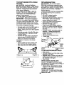
IMPORTANT:
This cutting machine is
capable of amputating hands and feet
and throwing objects. Failure to observe
the following safety instructions could
result in serious injury or death.
GENERAL
OPERATION
• Read, understand, and follow all
instructions in the manual and on the
machine before starting.
• Only allow responsible adults, who are
familiar with the instructions, to
operate the machine.
• Clear the area of objects such as
rocks, toys, wire, etc., which could be
picked up and thrown by the blade.
• Be sure the area is clear of other
people before mowing. Stop machine
if anyone enters the area.
• Never carry passengers.
• Do not mow in reverse unless absolutely necessary. Always look down
and behind before and while backing
• Be aware of the mower discharge
direction and do not point it at anyone
Do not operate the mower without
either the entire grass catcher or the
2
guard in place.
• Do not mow near drop-offs, ditches, or
embankments. The mower could
suddenly turn over if a wheel is over
the edge of a cliff or ditch, or if an edge
caves in.
• Do not mow on wet grass. Reduced
traction could cause sliding.
• Do nottry to stabilize the machine by
putting your foot on the ground.
• Do not use grass catcher on steep
slopes.
• Slow down beforeturning.
• Never leave a running machine
unattended. Always turn off blades, set
parking brake, stop engine, and
remove keys before dismounting.
• Turn off blades when not mowing.
• S.top engine before removing grass
catcher or unclogging chute.
• Mow only in daylight or good artificial
light.
• Do not operate the machine while
under the influence of alcohol or
drugs.
• Watch for traffic when operating near
or crossing roadways.
• Use extra care when loading or
unloading the machine into a trailer or
truck.
SLOPE
CHILDREN
Tragic accidents can occur if the operator
is not alert to the presence of children.
Children are often attracted to the
machine and the mowing activity. Never
assume that children will remain where
you last saw them.
• Keep children out of the mowing area
and under the watchful care of another
responsible adult.
• Be alert and turn machine off if
children enter the area.
• Before and when backing, _ook behind
and down for small children.
• Never carry chBdren.They may fall off
and be seriously injured or interfere
with safe machine operation.
• Never allow children to operate the
machine.
• Use extra care when approaching
blind corners, shrubs, trees, or other
objects that may obscure vision.
OPERATION
Slopes are a major factor related to lossof-control and tipover accidents, which
can result in severe injury or death. All
slopes require extra caution. If you
cannot back up the slope or if you feel
uneasy on it, do not mow it.
DO:
• Mow up and down slopes, not across.
• Remove obstacles such as rocks, tree
limbs, etc.
• Watch for holes, ruts, or bumps.
Uneven terrain could overturn the
machine. Tall grass can hide obstactes.
SERVICE
• Use slow speed. Choose a low gear
so that you will not have to stop or shift
while on the slope.
• Follow the manufacturer's recommen-
Use extra care in handling gasoline
and other fuels. They are flammable
and vapors are explosive.
- Use only an approved container.
- Never remove gas cap or add fuel
with the engine running. Allow
engine to cool before refueling. Do
not- smoke.
- Never refuel the machine indoors.
- Never store the machine or fuel
container inside where there is an
open flame, such as a water heater.
Never run a machine inside a closed
area.
• Keep nuts and bolts, especially blade
attachment bolts, tight and keep
equipment
in good condition.
• Never tamper with safety devices.
Check their proper operation regularly.
dations for wheel weights or counterweights to improve stability.
• Use extra care with grass catchers or
other attachments. These can change
the stability of the machine.
• Keep all movement on the slopes slow
and gradual. Do not make sudden
changes in speed or direction.
• Avoid starting or stopping on a slope. If
tires lose traction, disengage the
blades and proceed slowly straight
down the slope.
DO NOT:
• Do not turn on slopes unless necessary, and then, turn slowly and
gradually downhill, if possible.
3
• Grass catcher components are subjec_
to wear, damage, and deterioration,
which could expose moving parts or
allow objects to be thrown. Frequently
check components and replace with
manufacturer's recommended parts,
when necessary.
• Mower blades are sharp and can cut.
Wrap the blade(s) or wear gloves, and
use extra caution when servicing
them.
• Keep machine free of grass, leaves, or
other debris build-up. Clean oil or fuel
spillage. Allow machine to coot before
storing.
• Stop and inspect the equipment if you
strike an object. Repair, if necessary,
before restarting.
• Never make adjustments or repairs
with the engine running.
• Before and when backing, look behinC
and down for small children.
• Mow up and down slopes (15 ° Max),
not across.
• Remove obstacles such as rocks, tree
limbs, etc.
• Watch for holes, ruts, or bumps.
Uneven terrain could overturn the
machine. Tall grass can hide obstacles.
• Use slow speed. Choose a low gear
so that you will not have to stop or shift
while on the slope.
• Avoid starting or stopping on a slope. I1
tires lose traction, disengage the
blades and proceed slowly straight
down the slope.
• Do not turn on slopes unless necessary, and then, turn slowly and
gradually downhill, if possible.
• Check brake operation frequently.
Adjust and service as required.
• Be sure the area is clear of other
people before mowing. Stop machine
if anyone enters the area.
• Never carry passengers.
• Do not mow in reverse unless absolutely necessary. Always look down
and behind before and while backing.
• Never carry children. They may fall off
and be seriously injured or interfere
with safe machine operation.
• Keep children out of the mowing area
and under the watchful care of another
responsible adult.
• Be alert and turn machine off if
children enter the area.
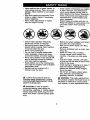
Look for this symbol to point out
important safety precautions. It means
CAUTION!H BECOMEAWARE!!!YOUR
SAFETY IS INVOLVED.
WARNING: The engine exhaust from
this product contains chemicals known to
the State of California to cause cancer,
birth defects, or other reproductive harm.
CAUTION: In order to prevent
accidental starting when setting up,
transporting, adjusting or making repairs
always disconnect spark plug wire and
place wire where it cannot contact spark
plug.
4
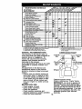
PRODUCT
SPECIFICATIONS
MAINTENANCE
GASOLINE
CAPACITY
AND TYPE:
3.5 GALLONS
UNLEADED
REGULAR
OILTYPE
_PI-SF/SG/SH):
SAE 30(ABOVE
SAE 5W-30
(BELOW 32°F)
)ILCAPACITY:
W/FILTER:
A Sears Maintenance Agreement is
available on this product. Contact your
nearest Sears store for details.
CUSTOMER
32°F)
GAP: .030")
3.5PINTS
VALVE
CHAMPION
RJ19LM
OR J19LM
INTAKE:
EXHAUST:.007"-.009"
GROUND
FORWARD:
5.5
(MPH):
REVERSE:
2.4
TIRE
PRESSURE:
FRONT:
REAR:
14 PSI
10 PSI
CHARGING
SYSTEM:
3 AMPS BA'FrERY
5 AMPS HEADLIGHT
BA'I-I'ERY:
AMP/HR:
30
MIN. CCA: 240
CASE SIZE:U1R
BLADE BOLT
TORQUE:
WARNING:
This tractor is equipped
with an internal combustion engine and
should not be used on or near any
unimproved forest-covered,
brushcovered or grass-covered land unless
the er_gine's exhaust system is equipped
with a spark arrester meeting applicable
local or state laws (if any). If a spark
arrester is used, it should be maintained
in effective working order by the operator.
In the state of California the above is
.004"-.006"
CLEARANCE:
SPEED
RESPONSIBILITIES
• Read and observe the safety rules.
• Follow a regular schedule in maintaining, caring for and using your tractor.
• Follow the instructions under "Maintenance" and "Storage" sections of this
owner's manual.
W/O FILTER: 3.0PINTS
SPARK PLUG:
AGREEMENT
required by law (Section 4442 of the
California Public Resources Code).
Other States may have similar laws.
Federal laws apply on federal lands. A
spark arrester for the muffler is available
through your nearest Sears Authorized
Service Center/Department
(See
REPAIR PARTS section of this manual).
27-35 FT. LBS
CONGRATULATIONS
on your purchase
of a Craftsman Tractor. It has been
designed, engineered and manufactured
to give you the best possible dependability and performance.
Should you experience any problem you
cannot easily remedy, please contact
your nearest Sears Authorized Service
Center. We have competent, well-trained
technicians and the proper tools to
service or repair this tractor.
Please read and retain this manual. The
instructions will enable you to assemble
and maintain your tractor properly.
Always observe the "SAFETY RULES".
5
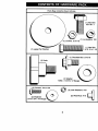
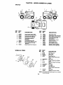
Parts Bag contents shown full size
(1) Hex Bolt
3/8-16 x 1
(1) Lockwasher
3/8
Locknut 5/16-18
(1) Hex Bolt
5/16-18 x 1-1/4
(1) Large Flat Washer
(1) Shoulder Bolt 5/16-18
(1) Knob
©
(1) Washer
17/32 x 1-3/16 x 12 Gauge
(2) Lock Washers
_
#10
#10x5/8
(2) Weld Nuts #10
3/16(2)_4as_r_auge@
6
I
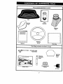
Parts packed separately in carton
Seat
Video
Cassette
Mulcher
Plate
Steedng
Boot
Steering
Wheel
Manual
I
Parts Bag
Parts Bag contents not shown full size
_
"_" i
I
I
(2) Latch Hook
Assemblies
_
Steering
Extension
Shaft
Slope Sheet
Steedng
Wheel
Insert
Steering Wheel
Adapter
(2) Keys
Your new tractor has been assembled at the factory with exception of those parts left
unassembled for shipping purposes. To ensure safe and proper operation of your
tractor all parts and hardware you assemble must be tightened securely. Use the
correct tools as necessary to insure proper tightness. Review the video cassette before
you begin.
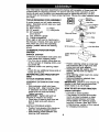
TOOLS
REQUIRED
_]
FOR ASSEMBLY
A socket wrench set will make assembly
easier. Standard wrench sizes you need
are listed below.
(1) 9/16"wrench
(2) 1/2" wrench
(1) 3/4" socket with
drive ratchet
/---_
(,_,_
_---'_
f/-_._----"_
(1) Pliers
(1) Utility knife
Steering
Wheel Insert
Hex Bolt
Lock Washer
Large Flat
Washer
Steering Wheel
(1) _re pressure gauge
(1) Phillips screwdriver
When right or left hand is mentioned in
this manual, it means, from your point of
view, when you are in the operating
position (seated behind the steering
wheel).
Steering Boot
Extension
Shaft
5/16 Locknut_5/16
Hex Bolt
TO REMOVETRACTOR FROM
CARTON
UNPACK
Lower Steering _-_-'j,
_ _
i"
Shaft
_, •
_.._./.--_'
T.ab
, "'-.
/
,_ Slots
CARTON
• Remove all accessible
loose parts and
parts boxes from shipping carton.
• Cut, from top to bottom, along lines on
all four corners of shipping carton, and
lay panels flat.
• Remove mower and packing materials.
• Position steering wheel so cross bars
are horizontal (left to right) and slide
inside boot and onto adapter.
• Assemble large fiat washer, 3/8 lock
washer, 3/8 hex bolt and tighten
securely.
• Snap steering wheel insert into center
of steering wheel.
• Remove protective materials from
tractor hood and grill.
IMPORTANT: Check for and remove any
staples in skid that may puncture tires
where tractor is to roll off skid.
• Check for any additional loose parts or
boxes and remove.
BEFORE
SKID
ROLUNG
AI-FACH
STEERING
ASSEMBLE
BOOT
TRACTOR
OFF
WHEEL
EXTENSION
SHAFT
AND
• Slide extension shaft onto lower
steering shaft. Align mounting holes
in extension and lower shafts and
install 5/16 hex bolt and Iocknut.
Tighten securely.
IMPORTANT:
_ghten bolt and nut
securely to 18-22 ft. Ibs. torque.
• Place tabs of steering boot over tab
slots in dash and push down to
secure.
INSTALL STEERING WHEEL
• Position front wheels of the tractor so
they are pointing straight forward.
• Slide steering wheel adapter onto
steering shaft extension.
HOW TO SET UP YOUR TRACTOR
CHECK BA'n'ERY
• Uft hood to raised position.
• If this battery is put into service after
month and year indicated on label
(label located between terminals)
charge battery for minimum of one
hour at 6-10 amps. (See "BAI-rERY"
in Maintenance section of this manual
for charging instructions).
8
-
.-"
-
Label
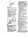
INSTALL SEAT
Adjust seat before tightening adjustment
knob.
• Remove cardboard packing on seat
pan.
• Place seat on seat pan and assemble
shoulder bolt. Tighten shoulder bolt
securely.
• Assemble adjustment knob and flat
washer loosely. Do not tighten.
• Lower seat into operating position
and sit on seat.
• Slide seat until a comfortable position
is reached which allows you to press
clutch/brake pedal all the way down.
• Get off seat without moving its
adjusted position.
• Raise seat and tighten adjustment ,
knob securely.
Seat
Shoulder
Bolt
Flat Washer
Adjustment
Knob
TO ROLLTRACTOR
OFF SKID (See
Operation section for location and
function of controls)
• Press lift lever plunger and raise
attachment lift |ever to its highest
position.
• Release parking brake by depressing
clutch/brake pedal.
• Place freewheel control in freewheeling position to disengage transmission
(See "TO TRANSPORT" in the Operation section of this manual).
• Roll tractor forward off skid.
• Remove banding holding discharge
guard up against tractor.
TO DRWE TRACTOR OFF SKID
_1_WARNING: Before starting, read,
understand and follow all instructions in
the Operation section of this manual. Be
sure tractor is in a well-ventilated area.
Be sure the area in front of tractor is
clear of other people and objects.
• Be sure all the above assembly steps
have been completed.
• Check engine oil level and fill fuel
tank with gasoline.
• Place freewheel control in 'transmission engaged" position.
• Sit on seat in operating position,
depress clutch/brake pedal and set
the .parking brake.
• Place motion control lever in neutral
(N) position.
• Press lift lever plunger and raise
attachment tiff lever to its highest
position.
• Start the engine. After engine has
started, move throttle control to idle
position.
• Release parking brake.
• Slowly move the motion control lever
forward and slowly drive tractor off
skid.
• Apply brake to stop tractor, set parking
brake and place motion control lever
in neutral position.
• Turn ignition key to "OFF" position.
Continue with the instructions that
follow.
iNSTALL MULCHER PLATE
• Install two latch hooks to mulcher plate
using screw, washer, lock washer, and
weld nut as shown.
NOTE: Pre-assemble weld nut to latch
hook by inserting weld nut from the top
with hook pointing down.
• Tighten hardware securely,
• Raise and hold deflector shield in
upright position.
• Place front of mulcher plate over front
of mower deck opening and slide into
place, as shown.
• Hook front latch into hole on front of
mower deck.
• Hook rear latch into hole on back of
mower deck.
/IL CAUTION: Do not remove discharge
guard from mower. Raise and hold guard
when attaching mulcher plate and allow
9 it to rest on plate while in operation.
CHECK FOR PROPER
OF ALL BELTS
Hook
Points
Weld Nut
POSITION
Latch
See the figures that are shown for
replacing motion and mower blade drive
belts in the Service and Adjustments
section ofthis manual. Verifythat the
belts are routed correctly.
CHECK BRAKE SYSTEM
Washer
After you learn how to operate your
tractor, check to see that the brake is
properly adjusted. See _TO ADJUST
BRAKE" in the Service and Adjustments
section of this manual.
Weld Nut
Lock
Washer
Latch
Hook
Nut
Washer
Plate
t/CHECKLIST
'_/Screw
PLEASE REVIEWTHE
CHECKLIST:
,/
All assembly instructions have been
completed.
,/" No remaining loose parts in carton.
/ Battery is properly prepared and
charged.
(Minimum 1 hour at 6
amps).
/ Seat is adjusted comfortably and
tightened securely.
/All tires are properly inflated. (For
shipping purposes, the tires were
overinflated at the factory).
,/Be sure mower deck is properly
leveled side-to-side/front-to-rear
for
best cutting results. (Tires must be
properly inflated for leveling).
,/" Check mower and drive belts. Be sure
they are routed properly around
pulleys and inside all belt keepers.
4' Check wiring. See that all connections
are still secure and wires are properly
clamped.
,/Before driving tractor, be sure fTeewheel control is in drive position.
Shield
Latch Hooks
TO CONVERTTO
DISCHARGING
FOLLOWING
BAGGING
OR
Simply remove mulcher plate and store
in a safe place. Your mower is now ready
for discharging or installation of optional
grass catcher accessory.
NOTE: It is not necessary to change
blades. The mulcher blades are designed for discharging and bagging also.
CHECK TIRE PRESSURE
The tires on your tractor were overinfiated at the factory for shipping purposes. Correct tire pressure is important
for best cutting performance.
• Reduce tire pressure to PSI shown in
"PRODUCT SPECIFICATIONS"
section of this manual.
WHILE LEARNING HOWTO USE YOUR
TRACTOR, PAY EXTRAATrENTION
TO
THE FOLLOWING IMPORTANT ITEMS:
/
/
For best cutting results, mower housing
should be properly leveled. See "TO
LEVEL MOWER HOUSING" in the
Service and Adjustments
manual.
regular unleaded gasoline.
Become familiar with all controls - their
location and function. Operate them
before you start the engine.
/ Be sure brake system is in safe
operating condition.
,/It is important to purge the transmission before operating your tractor for
the first time. Follow proper starting
and transmission purging instructions
(See =3"0 START ENGINE" and
=PURGE TRANSMISSION"
in the
Operation section of this manual).
/
CHECK DECK LEVELNESS
section of this
10
Engine oil is at proper level.
Fuel tank is filled with fresh, clean,
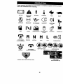
These symbols may appear on your tractor or in literature supplied with the product.
Learn and understand their meaning.
& ÷
BATTERY
CAUTION OR
WARNING
REVERSE
FORWARD
FAST
SLOW
E.G,.EO._I_
ENO,.EOFFIxI
O,LPRESSO.E_w
LIG_SO._]
O%+_+@
FUEL
CHOKE
MOWER HEIGHT
PARKING BRAKE
LOCKED
UNLOCKED
MOWER LIFT
R N H L
A'UI'ACHMENT
CLUTCH ENGAGED
REVERSE
NEUTRAL
A'i-I'ACHMENT
IGNITION
HIGH
LOW
KEEP AREA CLEAR
PARKING BRAKE
SLOPE HAZARDS
(SEE SAFETY RULES SECTION)
CLUTCH DISENGAGED
FREE WHEEL
(AutomatlcModelsonly)
DANGER, KEEP HANDS AND FEET AWAY
11
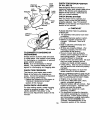
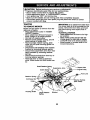
KNOWYOUR
TRACTOR
READ THIS OWNER'S MANUAL AND SAFETY RULES BEFORE OPERATING
YOUR TRACTOR
Compare the illustrations with your tractor to familiarize yourself with the locations of
various controls and adjustments, Save this manual for future reference.
Switch
Attachment
Clutch Lever
Ignition
Ammeter
Lever
Plunger
Throttle
L_ Lever
Clutch/
Brake
Height
Adjustment
Knob
Free Wheel
Ig Brake Lever
Motion
Control
Lever
Ourtractomcon_rm
tothes_e_standa_softhe
In_ff_e.
AMMETER
- Indicates charging (+) or
discharging (-) of battery.
A'n'ACHMENT
CLUTCH LEVER - Used
American
N_ionalStanda_s
MOTION CONTROL LEVER - Selects the
speed and direction of tractor.
FREEWHEEL
CONTROL
- Disengages
transmission for pushing or slowly
towing the tractor with the engine off.
IGNITION SWITCH - Used for starting
and stopping the engine.
LIFT LEVER PLUNGER - Used to
release attachment lift lever when
changing its position.
LIGHT SWITCH - Turns the headlights on
and off.
PARKING BRAKE LEVER - Locks
clutch/brake pedal into the brake
position.
THROTTLE
CONTROL - Used to control
to engage the mower blades, or other
attachments mounted to your tractor.
ATTACHMENT
LIFT LEVER - Used to
raise; lower, and adjust the mower deck
or other attachments mounted to your
tractor.
CHOKE CONTROL
- Used when starting
a cold engine.
CLUTCH/BRAKE
PEDAL - Used for
declutching and braking the tractor and
starting the engine.
HEIGHT ADJUSTMENT
KNOB - Used to
adjust the mower cutting height.
engine
12
speed,
The operation of any tractor can result in foreign objects thrown into
the eyes, which can result in severe eye damage. Always wear safety
glasses or eye shields while operating your tractor or performing any
adjustments or repairs. We recommend a wide vision safety mask
over spectacles or standard safety glasses.
HOW TO USE YOUR TRACTOR
TO SET PARKING
BRAKE
Your tractor is equipped with an operator
presence sensing switch. When engine
is running, any attempt by the operator to
leave the seat without first setting the
parking brake will shut off the engine.
• Depress clutch/brake pedal into full
"BRAKE" position and hold.
• Place parking brake lever in "ENGAGED" position and release pressure from clutch/brake pedal. Pedal
should remain in "BRAKE" position.
Make sure parking brake will hold
tractor secure.
Attachment Clutch Lever
Choke
Control_
X
T W!
"Engaged" Position
_
"Disengaged"
_k,._k,..J-_,_'_'(
" _'_ Position
• Never use choke to stop engine.
IMPORTANT:
Leaving the ignition
switch in any position other than "OFF"
will cause the battery to be discharged,
(dead).
NOTE: Under certain conditions when
tractor is standing idle with the engine
running, hot engine exhaust gases may
cause "browning" of grass. To eliminate
this possibility, always stop engine when
stopping tractor on grass areaS.
CAUTION:
Always stop tractor
completely, as described above, before
leaving the operator's position; to empty
grass catcher, etc.
TO USE THRO'I-FLE
CONTROL
Always operate engine at full throttle.
• Operating engine at less than full
throttle reduces the battery charging
rate.
• Full throttle offers the best bagging
and mower performance.
TO USE CHOKE
CONTROL
Parking
ControF-_ '\ "_ \ ,._\\_
Brake
-.-__,
_', \ "_/ I
"Engaged"
Clutch/
"_._ ____
-Ll"....--s"Positio n .
Use choke control whenever you are
starting a cold engine. Do not use to start
a warm engine.
• To engage choke control, p011 knob
out. Slowly push knob in to disengage..
TO MOVE FORWARD AND BACKWARD
Brake_
"_Height "i--_.
"Dis .e.nga.ged".._"
._,,_
_,__
._,
Position
Knob
"Brake"
STOPPING
MOWER
BLADES
Motion
Control
Lever
Position
-
• To stop mower blades,move
attachment clutch lever to "DISENGAGED"
position.
GROUND DRIVE -
The direction and speed of movement is
controlled by the motion control lever.
• Start tractor with motion control lever in
neutral (N) position.
• Release parking brake and.clutch/
brake pedal.
• Slowly move motion control lever to
desired position.
• To stop ground drive, depress clutch/
brake pedal into full "BRAKE" position.
• Move motion control lever to neutral
(N) position.
IMPORTANT:
The motion control lever
does not return to neutral (N) position
when the clutch/brake pedal is depressed.
ENGINE • Move throttle control to slow positionl
NOTE: Failure to move throttle control to
slow position and allowing engine to idle
before stopping may cause engine to
"backfire".
• Turn ignition key to "OFF" position and
remove key. Always remove key when
leaving tractor to prevent unauthorized
use.
TO ADJUST
HEIGHT
MOWER
cUTrlNG
The cutting height is controlled by
turning the height adjustment knob in
desired direction.
• Turn knob clockwise ((-N) to raise
cutting height.
• Turn knob counterclockwise (P-_)to
lower cutting height.
13
The cutting height range is approximately 1-1/2" to 4". The heights are
measured from the ground to the blade
tip with the engine not running. These
heights are approximate and may vary
depending upon soil conditions, height
of grass and types of grass being
mowed.
• The average lawn should be cut to
approximately 2-1/2 inches during the
cool season and to over 3 inches
during hot months. For healthier and
better looking lawns, mow often and
after moderate growth.
• For best cutting performance, grass
over 6 inches in height should be
mowed twice. Make the first cut
relatively high; the second to desired
height.
TO ADJUST
GAUGE
• Lower mower with attachment
control.
• Start mower blades by engaging
attachment clutch control.
• TO STOP MOWER BLADES - disengage attachment clutch control.
A CAUTION:
DO not operate the mower
without either the entire grass catcher, on
mowers so equipped, or the discharge
guard in place.
Attachment Clutch Lever _Engaged"
Position
Lift
Lever High
Position
"-Low
Position
WHEELS
Position
Guard
Gauge wheels are properly adjusted
when they are slightly off the ground
when mower is at the desired cutting
height in operating position. Gauge
wheels then keep the deck in proper
position to help prevent scalping in most
terrain conditions.
• Adjust gauge wheels with tractor on a
fiat level surface.
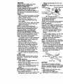
TO OPERATE
ON HILLS
CAUTION:
Do not drive up or down
hills with slopes greater than 15 ° and do
not drive across any slope.
• Choose the slowest speed before
starting up or down hills.
• Avoid stopping or changing speed on
hills.
• Adjust mower to desired cutting height
(See 'TO ADJUST MOWER CU'FI'ING
HEIGHT" in the Operation section of
this manual).
• With mower in desired height of cut
position, gauge wheels should be
assembled so they are slightly off the
ground. Install gauge wheel in
appropriate hole with shoulder bolt, 3/
8 washer, and 3/8-16 Iocknut and
tighten securely.
• Repeat for opposite side installing
gauge wheel in same adjustment hole.
• If slowing is necessary, move throttle
control lever to slower position.
• If stopping is absolutely necessary,
push clutch/brake pedal quickly to
brake position and engage parking
brake.
• Move motion control lever to neutral
(N) position.
IMPORTANT: The motion control lever
does not return to neutral (N) position
when the clutch/brake pedal is depressed.
• To restart movement, slowly release
parking brake and clutch/brake pedal.
• Slowly move motion control lever to
slowest setting.
• Make all turns slowly.
Locknut_.---_
_ _,_
Gauge
_
-_
"_l_
Wheel
-%_._
A_
_lr _,_X_
Mounting
_
_
'"_i"_-_J
Bracket_
_
_ f
3/8 Washer -_"'_
f:_
yShoulder
Gauge Wheel''"-,,_v-_Bolt
TO TRANSPORT
When pushing or towing your tractor, be
sure to disengage transmission by
placing freewheel control in freewheeling position. Free wheel control is
located at the rear drawbar of tractor.
• Raise attachment lift to highest
position with attachment lift control.
TO OPERATE MOWER
Your tractor is equipped with an operator
presence sensing switch. Any attempt by
the operator to leave the seat with the
engine running and the attachment
clutch engaged will shut off the engine.
• Select desired height of cut.
lift
14
• Pullfreewheelcontrolout and
ADD GASOUNE
down
into the slot and release so it is held in
• Fill fuel tank. Use fresh, clean, regula
unleaded gasoline with a minimum of
87 octane. (Use of leaded gasoline
will increase carbon and lead oxide
deposits and reduce valve life). Do
not mix oil with gasoline. Purchase
fuel in quantities that can be used
within :30 days to assure fuel freshness.
IMPORTANT:
When operating in
temperatures below 32°F(0°C),
use
fresh, clean winter grade gasoline to
help insure good cold weather starting.
_i, WARNING:
Experience indicates tha
alcohol blended fuels (called gasohol or
using ethanol or methanol) can attract
moisture which _eads to separation and
formation of acids during storage. Acidic
gas can damage the fuel system of an
engine while in storage. To avoid engim
problems, the fuel system should be
emptied before storage of 30 days or
longer. Drain the gas tank, start the
engine and let it run until the fuel lines
and carburetor are empty. Use fresh fue
next season., See Storage Instructions
for additional information.
Never use
the disengaged position.
• Do not push or tow tractor at more
than two (2) MPH.
• To reengage transmission, reverse
above procedure.
NOTE: To protect hood from damage
when transporting your tractor on a truck
or a trailer, be sure hood is closed and
secured to tractor. Use an appropriate
means of tying hood to tractor (rope,
cord, etc.).
TOWING CARTS AND OTHER
A'n'ACHMENTS
Tow only the attachments that are
recommended by and comply with
specifications of the manufacturer of your
tractor. Use common sense when towing.
Too hea W of a load, while on a slope, is
dangerous. 13res can lose traction with
the ground and cause you to lose control
of your tractor.
BEFORE
CHECK
STARTING
ENGINE
THE
engine or carburetor cleaner products in
the fuel tank or permanent damage may
occur,
_, CAUTION:
Fill
filler neck. Do not
spilled oil or fuel.
use gaso{ine near
ENIGNE
OIL LEVEL
to bottom of gas tank
overfill. Wipe off any
Do not store, spill or
an open flame.
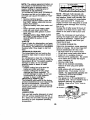
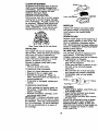
TO START ENGINE
• The engine in your tractor has been
shipped, from the factory, already filled
with summer weight oil.
• Check engine oil with tractor on level
ground.
• Remove oil fill cap/dipstick
and wipe
clean, reinsert the dipstick and screw
cap tight, wait for a few seconds,
remove and read oil level. If neces-
When starting the engine fer the first time
or if the engine has run out of fuel, it will
take extra cranking time to move fuel
from the tank to the engine.
• Be sure freewheel control is in the
transmission engaged position.
• Sit on seat in operating position,
depress clutch/brake pedal and set
parking brake.
• Place motion control lever in neutral
(N) position.
• Move attachment clutch to "DISEN-
sary, add oil until "FULL" mark on
dipstick is reached. Do not overfill.
• For cold weather operation you should
change oil for easier starting (See "OIL
VISCOSITY
CHART" in the Maintenance section of this manual).
• To change engine oil, see the Maintenance section in this manual.
GAGED" position.
• Move throttle control to fast position
• Pull choke control out for a cold
engine start attempt. For a warm
engine start attempt the choke control
may not be needed.
NOTE: Before starting, read the warm
and cold starting procedures
below.
15
• Insert key into ignition and turn key
clockwise to =START" position and
release key as soon as engine starts.
Do not run starter continuously for
more than fifteen seconds per minute.
If the engine does not start after
several attempts, push choke control
in, wait a few minutes and try again. If
engine still does not start, pull the
choke control out and retry.
• The attachments can be used during
the engine warm-up period after the
transmission has been warmed up
and may require the choke control be
pulled out slightly.
NOTE: If at a high altitude (above 3000
feet) or in cold temperatures (below 32
F) the carburetor fuel mixture may need
to be adjusted for best engine performance. See "TO ADJUST CARBURETOR" in the Service and Adjustments
section of this manual.
WARM WEATHER STARTING (50 ° F and
above)
• When engine starts, slowly push
choke control in until the engine
begins to run smoothly. If the engine
starts to run roughly, pull the choke
control out slightly for a few seconds
and then continue to push the control
in slowly.
• The attachments and ground drive can
now be used. If the engine does not
accept the load, restart the engine and
allow it to warm up for one minute
using the choke as described above.
PURGE TRANSMISSION
CAUTION: Never engage or disengage freewheel lever while the engine is
running.
To ensure proper operation and performance, it is recommended that the
transmission be purged before operating
tractor for the first time. This procedure
will remove any trapped air inside the
transmission which may have developed
during shippingof your tractor.
IMPORTANT; Should your transmission
require removal for service or replacement, it should be purged after reinstallation before operating the tractor.
• Place tractor safely on level surface
with engine off and parking brake set.
• Disengage transmission by placing
freewheel control in freewheeling
position (See "TO TRANSPORT" in
this section of manual).
• Sitting in the tractor seat, start engine.
After the engine is running, move
throttle control to slow position. With
motion control lever in neutral (N)
position, slowly disengage clutch/
brake pedal.
• Move motion control lever to full
forward position and hold for five (5)
seconds. Move lever to full reverse
_osition and hold for five (5) seconds.
epeat this procedure three ,(3) times.
NOTE; During this procedure there will
be no movement of drive wheels. The air
is being removed from hydraulic drive
system.
• Move motion control lever to neutral
(N) position. Shut- off engine and set
parking brake.
• Engage transmission by placing
freewheel control in driving position
(See 'I"O TRANSPORT" in this section
of manual).
COLD WEATHER STARTING (50° F and
below)
• When engine starts, slowly push
choke control in until the engine
begins to run smoothly. Continue to
push the choke control in small steps
allowing the engine to accept small
changes in speed and load, until the
choke control is fully in. If the engine
starts to run roughly, pull the choke
control out slightly for a few seconds
and then continue to push the control
in slowly. This may require an engine
warm-up period from several seconds
to several minutes, depending on the
temperature.
AUTOMATICTRANSMISSION
WARM UP
• Before driving the unit in cold weather,
the transmission should be warmed up
as follows:
• Be sure the tractor is on level
ground.
• Place the motion control lever in
neutral. Release the parking brake
and let the clutch/brake
slowly return to operating position.
• Allow one minute for transmission to
warm up. This can be done during
the engine warm up period.
16
• Sitting in the traotor seat, start engine.
After the engine is running, move
throttle control to half (1/2) speed. W'dh
motion control lever in neutral (N)
position, slowly disengage clutch/
brake pedal.
• Slowly move motion control lever
forward, after the tractor moves
approximately five (5) feet, slowly
move motion control lever to reverse
position. After the tractor moves
approximately five (5) feet return the
motion control lever to the neutral (N)
position. Repeat this procedure with
the motion control lever three (3)
times.
• Your tractor is now purged and now
ready for normal operation.
MOWING TIPS
• Mower should be properly leveled for
best mowing performance. See =TO
LEVEL MOWER HOUSING" in the
Service and Adjustments section of
this manual.
• The left hand side of mower should be
used for trimming.
• Drive so that clippings are discharged
onto the area that has been cut. Have
the cut area to the right of the tractor.
This will result in a more even distril_ution of clippings and more uniform
cutting.
• When mowing large areas, start by
turning to the right so that clippings wilt
discharge away from shrubs, fences,
driveways, etc. After one or two
rounds, mow in the opposite direction
making left hand tums until finished.
• If grass is extremely tall, it should be
mowed twice to reduce load and
possible fire hazard from dried
clippings. Make first cut relatively
high; the second to the desired height.
• Do not mow grass when it is wet. Wet
grass will plug mower and leave
undesirable clumps. Allow grass to
dry before mowing.
• Always operate engine at full throttle
when mowing to assure better mowing
performance and proper discharge of
material. Regulate ground speed by
selecting a low enough gear to give
the mower cutting performance as well
as the quality of cut desired.
• When operating attachments, select a
• ground speed that will suit the terrain
and give best performance of the
attachment being used.
1
MULCHING
MOWING TIPS
IMPORTANT: For best performance,
keep mower housing free of built-up
grass and trash. Clean after each use.
• The special mulching blade will recut
the grass clippings many times and
reduce them in size so that as they fall
onto the lawn they will disperse into
the grass and not be noticed. Also, the
mulched grass will biodegrade quickly
to I_rovidenutrients for the lawn.
Always mulch with your highest
engine (blade) speed as this will
provide the best recutting action of the
blades.
• Avoid cutting your lawn when it is wet.
Wet grass tends to form clumps and
interferes with the mulching action.
The best time to mow your lawn is the
early afternoon. At this time the grass
has dried and the newly cut area will
not be exposed to the direct sun.
• For best results, adjust the mower
cutting height so that the mower cuts
off only the top one-third of the glass
blades. For extremely heavy mulching,
reduce your width of cut on each pass
and mow slowly.
• Certaintypas of grass and grass
conditions may require that an area be
mulched a second time to completely
hide the clippings. When doing a
second cut, mow across or perpendicular to the first cut path.
• Change your cutting pattern from week
to week. Mow north to south one week
then change to east to west the next
week. This will help prevent matting
and graining of the lawn.
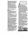
Max 1/'3"
17
MAINTENANCE
SCHEDULE
Check Tire
Brake
Pressure
OperaUon
R
Check Operator Presence and
Interlock Systems
Check for Loose Fasteners
A
Sharpen/Replace
T
Lubrice_on Chart
0
Chec_ Battery Level
Clean Battery and Terminals
T
R
_-,/_
__/_,y
_
v',
v'
Mower Blades
Blade Bait(s)
v'
v'
Check Transaxla Cooltng
Adjust
._o_ ._JP_'_
Tension
Adjust Motion Drive Beti(s) Tension
Check
Engine
Change
Oil Level
t/
I/
Engine Oil
E
Clean
N
Clean Air Screen
Air Filter
GI
Inspect Muffler/Spark Arrester
Replace Oil Filter (if equipped)
N
Clean
Engine
Replace
Cooling
v'
Fins
Spark Plug
v',
Replace Air Filter Paper Cartridge
v'
Replace Fuel Filter
1
2
3
4
- Change more often when opef_tlrlg under a hea W Jo_d or irl high ambient temperature.
- Service more often when _
in dirty or dusty conditions.
- If aquipp_d wRh og fleer, change OII avery 50 hours.
- RepLace ble<ine more often when mo_ng in =_ndy soil.
GENERAL
RECOMMENDATIONS
LUBRICATION CHART
The warranty on this tractor does not
cover items that have been subjected to
operator abuse or negligence. To
receive full value from the warranty,
operator must maintain tractor as
instructed in this manual.
Zerk
Zerk
OFront Wheel
Bearing
Zerk
Some adjustments will need to be made
periodically to properly maintain your
tractor.
All adjustments in the Service and
Adjustments section of this manual
should be checked at least once each
season.
• Once a year you should replace the
spark plug, clean or replace air filter,
and check blades and belts for wear.
A new spark plug and clean air filter
assure proper air-fuel mixture and
help your engine run better and last
longer.
BEFORE EACH USE
Check engine oil level.
Check brake operation.
Check tire pressure.
Check operator presence and
interlock systems for proper operation.
• Check for loose fasteners.
5 - If equipped _
adjustable sy=dem,
6 - NOt required if equipped with ff_intet_ance-free
battery,
7 - _ghten
front axle pivot bolt to 35 ft,-Ibs, ma_dmum.
DO not overtighten.
Zerk
I
i
(_Seneral Purpose Grease
_)Refer to Maintenance "Engine" Section
IMPORTANT:
Do not oil or grease the
pivot points which have special nylon
bearings. Viscous lubricants will attract
dust and dirt that will shorten the life of
the self-lubricatin_ bearings. If you feel
they must be lubncated, use only a dry,
powdered graphite type lubricant
sparingly.
•
•
•
•
18
TRAC1OR
Always observe safety rules when
performing any maintenance.
BRAKE OPERATION
If tractor requires more than six (6) feet
stopping distance at high speed in
highest gear, then brake must be
adjusted. (See "TO ADJUST BRAKE" in
the Service and Adjustments section of
this manual).
TIRES
• Maintain proper air pressure in all tires
(See "PRODUCT SPECIFICATIONS"
section of this manual).
• Keep tires free of gasoline, oil, or
insect control chemicals which can
harm rubber.
• Avoid stumps, stones, deep ruts, sharp
objects and other hazards that may
cause tire damage.
NOTE: To seal tire punctures and
prevent flat tires due to slow leaks, tire
sealant may be purchased from your
local parts dealer. "Fire sealant also
prevents tire dry rot and corrosion.
OPERATOR
PRESENCE
SYSTEM
Be sure operator presence and interlock
systems are working properly. If your
tractor does not function as described,
repair the problem immediately.
• The engine should not start unless the
clutch/brake pedal is fully depressed
and attachement clutch control is in
• Tighten bolt securely (27-35 Ft. Lbs.
torque).
IMPORTANT:
Blade bolt is Grade 8 he_
treated.
T,o_ "g =,_.... _..
Mandrel Assembl_
the disengaged position.
• When the engine is running, any
attempt by the operator to leave the
seat without first setting the parking
brake should shut off the engine.
• When the engine is running and the
attachment clutch is engaged, any
attempt by the operator to leave the
seat should shut off the engine.
• The attachment clutch should never
......
_
H;le
_
Lock Washe_'__
_.Star
_----Hex Bolt (Grade L_
*A Grade 8 heat treated bolt can be ident'die_
by six lines on the bolt head.
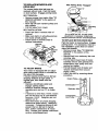
TO SHARPEN BLADE
NOTE: We do not recommend sharpen
ing blade - but if you do, be sure the
blade is balanced.
Care should be taken to keep the blade
balanced.
An unbalanced
blade will
cause excessive vibration and eventual
damage to mower and engine.
• The blade can be sharpened with a
file or on a grinding wheel. Do not
attempt to sharpen while on the
mower.
• To check blade balance, you will neec
a 5/8" diameter steel bolt, pin, or a
cone balancer.
(When using a cone
balancer, follow the instructions
supplied with balancer.)
NOTE: Do not use a nail for balancing
blade. The lobes of the center hole may
appear to be centered, but are not.
• Slide blade on to an unthreaded
portion of the steel bolt or pin and hol_
the bolt or pin parallel with the grounc
If blade is balanced, it should remain
in a horizontal position.
If either end (
the blade moves downward, sharpen
the heavy end until the blade is
balanced.
operate unless the operator is in the
seat.
BLADE CARE
For best results mower blades must be
kept sharp. Replace bent or damaged
blades.
BLADE REMOVAL
• Raise mower to highest position to
allow access to blades.
• Remove hex bolt, lock washer and flat
washer securing blade.
• Install new or resharpened
blade with
trailing edge up towards deck as
shown.
IMPORTANT:
To ensure proper assembly, center hole in blade must align with
star on mandrel assembly.
• Reassemble
hex bolt, _ock washer and
19
flat washer in exact order as shown.
Center
5/8" B_.
.
-
_
_
_._
_ aQe
BA'B'ERY
Your tractor has a battery charging
system which is sufficient for normal use
However, periodic charging of the batter
with an automotive charger will extend
its life.
i
Keep
tight.
eep battery
battery bolts
and terminals
clean.
Keep small vent holes open.
" Recharge
at 6-10 amperes
for 1 hour
NOTE: The original equipment battery on
your tractor is maintenance free. Do not
attempt to open or remove caps or
covers. Adding or checking level of
electrolyte is not necessary,
TO CLEAN BATI'ERY AND TERMINALS
Corrosion and dirt on the battery and
terminals can cause the battery to "leak"
power,
Remove terminal guard.
Disconnect BLACK battery cable first
then RED battery cable and remove
battery from tractor.
• Rinse the battery with plain water and
dry.
• Clean terminals and battery cable
ends with wire brush until bright.
• Coat terminals with grease or petroleum jelly.
• Reinstall battery (See "REPLACING
BATTERY" in the SERVICE AND
ADJUSTMENTS section of this
manual).
V-BELTS
Check V-belts for deterioration and wear
after 100 hours of operation and replace
if necessary. The belts are not adjustable.
Replace belts if they begin to slip from
wear,
TRANSAXLE COOLING
The transmission fan and cooling fins
should be kept clean to assure proper
cooling.
Do not attempt to clean fan or transmission while engine is running or while the
transmission is hot. To prevent possible
damage to seals, do not use high
pressure water or steam to clean
transaxle,
• Inspect cooling fan to be sure fan
blades are intact and clean.
• Inspect cooling fins for dirt, grass
clippings and other materials. To
prevent damage to seals, do not use
compressed a=ror high pressure
sprayer to clean coohng fins.
TRANSAXLE
PUMP FLUID
The transaxle was sealed at the factory
and fluid maintenance is not required for
the life of the transaxle. Should the
transaxle ever leak or require servicing,
contact your nearest authorized service
center/department.
NOTE: Although multi-viscosity oils
(5W30, 10W30 etc.) improve starting in
cold weather, these multi-viscosity oils
will result in increased oil consumption
when used above 32°F. Check your
engine oil level more frequently to avoid
possible engine damage from running
low on oil.
Change the oil after every 50 hours of
operation or at least once a year if the
tractor is not used for 50 hours in one
year.
Check the crankcase oil level before
starting the engine and after each eight
(8) hours of operation_ Tighten oil fill
cap/dipstick
securely each time you
check the oil level.
TO CHANGE ENGINE OIL
Determine temperature range expected
before oil change. All oil must meet API
service classification SF, SG or SH.
• Be sure tractor is on level surface.
• Oil will drain more freely when warm.
• Catch oil in a suitable container.
• Remove oil fill cap/dipstick. Be careful
not to allow dirt to enter the engine
when changing oil.
• Remove drain plug.
• After oil has drained completely,
replace oil drain plug and tighten
securely.
• Refill engine with oil through oil fill
dipstick tube. Pour slowly. Do not
overfill. For approximate capacity see
"PRODUCT SPECIFICATIONS"
section of this manual.
• Use gauge on oil fill cap/dipstick for
checking level. Be sure dipstick cap is
tightened securely for accurate
reading. Keep oil at "FULL" line on
dipstick.
ENGINE
LUBRICATION
Oil Drain
Only use high quality detergent oil rated
with API service classification SF, SG, or
SH. Select the oil's SAE viscosity grade
according to your expected operating
temperature.
Oil Fill
Dipstsick
2O
CLEAN AIR SCREEN
Air screen must be kept free of dirt and
chaff to prevent engine damage from
overheating.
Clean with a wire brush or
compressed air to remove dirt and
stubborn dried gum fibers.
ENGINE COOUNG
FINS
Remove any dust, dirt or oil from engine
cooling fins to prevent engine damage
from overheating. Air guide covers must
be removed. Remove side panels and
hood (See 'TO REMOVE HOOD AND
GRILLASSEMBLY" in the Service and
Adjustments section of this manual).
Foam Pre-Cleane_idg
e
MUFFLER
Inspect and replace corroded muffler
and spark arrester (if equipped) as it
could create a fire hazard and/or
damage.
SPARK PLUGS
Replace spark plugs at the beginning of
each mowing season or after every I00
hours of operation, whichever occurs
first. Spark plug type and gap setting are
shown in "PRODUCT SPECIFICATIONS"
section of this manual.
IN-LINE FUEL FILTER
Clean These Areas of Dirt and Debris
AIR FILTER
Your engine will not run properly using a
dirty air filter. Clean the foam pre-cleaner
after every 25 hours of operation or
every season. Service paper cartridge
every 100 hours of operation or every"
season, whichever occurs first.
Service air cleaner more often under
dusty conditions.
• Remove knobs and cover.
TO SERVICE PRE-CLEANER
The fuel filter should be replaced once
each season, if fuel filter becomes
clogged, obstructing fuel flow to carburetor, replacement is required.
• With engine cool, remove filter and
plug fuel line sections.
• Place new fuel filter in position in fuel
line with arrow pointing towards
carburetor.
• Be sure there are no fuel line leaks
and clamps are properly positioned.
• Immediately wipe up any spilled
gasoline.
• Wash it in liquid detergent and water;
• Squeeze it dry in a clean cloth.
• Saturate it in engine oil. Wrap it in
clean, absorbent cloth and squeeze to
remove excess oil.
• If very dirty or damaged, replace precleaner.
TO SERVICE
C':u_PFi_
Clamp
CARTRIDGE
CLEANING
• Clean cartridge by tapping gently on
fiat surface. If very dirty or damaged,
replace cartridge.
• Reinstall precleaner cartridge, cover
and secure with knobs.
IMPORTANT:
Petroleum solvents, such
as kerosene, are not to be used to clean
Clean en_]ine, battery seat, finish, etc.
of all foreign matter.
Keep finished surfaces and wheels
free of all gasoline, oil, etc.
• Protect painted surfaces with automotive type wax.
We do not recommend using a garden
hose to clean your tractor unless the
electrical system, muffler, air filter and
carburetor are covered to keep water out.
Water in engine can result in a shortened engine life.
i
the cartridge. They may cause deterioration of the cartridge.
Do not oil cartridge.
Do not use pressurized air to clean or
dry cartridge.
21
_CAUTION:
Before performing any service or adjustments:
• Depress clutch/brake pedal fully and set parking brake.
• Place motion control lever in neutral (N) position.
• Place attachment clutch in "DISENGAGED" position.
• Turn ignition key "OFF" and remove key.
• Make sure the blades and all moving parts have completely stopped.
• Disconnect spark plug wire from spark plug and place wire where it cannot
come in contact with plug.
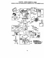
TRACTOR
IMPORTANT: If an attachment other than
the mower deck is to be mounted on the
tractor, remove the front links and hook
the clutch spring onto square hole in
frame.
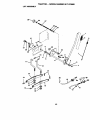
TO INSTALL MOWER
• Raise attachment lift lever to its highest position.
• Slide mower under tractor with discharge guard to right side of tractor.
Lower lift lever to its lowest position.
Install mower in reverse order of removal instructions.
TO REMOVE MOWER
Mower will be easier to remove from the
right side of tractor.
• Place attachment clutch in "DISENGAGED" position.
• Move attachment lift lever forward to
lower mower to its lowest position.
• Roll belt off engine pulley.
• Remove small retainer spring, and lift
clutch spring off pulley bolt.
• Remove large retainer spring, slide
collar off and push housing guide out
of bracket.
• Disconnect anti-swaybar from chassis
bracket by removing retainer spring.
• Disconnect suspens0on arms from rear
deck brackets by removing retainer
springs.
• Disconnect front links from deck by removing retainer springs.
• Raise lift lever to raise suspension
arms. Slide mower out from under tractot.
Small Retainer Spring
- Square Hole
Pulley
Unk
Anti-Sway
Collar
Housing
Retainer Springs
(Both Sides)
Large Retainer
Spring
Bracket
22
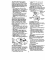
TO LEVEL MOWER
HOUSING
Adjust the mower while tractor is parked
on level ground or driveway. Make sure
tires are properly inflated (See "PRODUCT SPECIFICATIONS" section of this
manual). If tires are over or
underinflated, you will not properly
adjust your mower.
SIDE-TO-SIDE
ADJUSTMENT
• Raise mower to its highest position.
• At the midpoint of both sides of mower,
measure height from bottom edge of
mower to ground.
Distance "A" on
both sides of mower should be the
same or within 1/4" of each other.
• If adjustment is necessary, make
adjustment on one side of mower only.
• To raise one side of mower, tighten _ift
link adjustment
nut on that side.
• To lower one side of mower, loosen lift
• Before making any necessary adjustmerits, check that both front links are
equal in length. Both links should be
approximately 10-3/8".
• If links are not equal in length, adjust
one link to same length as other link.
• To lower front of mower loosen nut "E
on both front links an equal number o
turns.
• When distance "D" is 1/8" to 1/2" Iowe
at front than rear, tighten nuts "F"
against trunnion on both front links.
• To raise front of mower, loosen nut "F
from trunnion on both front links.
Tighten nut "E" on both front links an
equal number of turns.
• When distance "D" is 1/8" to 1/2" Iowc
at front than rear, tighten nut "F"
against trunnion on both front links.
• Recheck side-to-side adjustment.
link adjustment nut on that side.
NOTE:Each full turn of adjustment
nut
will change mower height about 1/8".
• Recheck measurements
after adjusting.
Bottom edge of
,Mandrel
Bottom edge of
mowe_
r°und
Both Front Links Should be Equal in Length
Suspension
Lift Unk Adjustment Nut
"E"
Nut
FRONT-TO-BACKADJUSTMENT
IMPORTANT:
Deck must be level side-to
side. If the following front-to-back
adjustment is necessary, be sure to
adjust both front links equally so mower
will stay level side-to-side.
To obtain the best cutting results, the
mower housing should be adjusted so
that the front is approximately
1/8" to 1/2"
lower than the rear when the mower is in
Front Links
its highest position.
Check adjustment on right side of tractor.
Measure distance "D" directly in front
and behind the mandrel at bottom edge
of mower housing as shown.
23
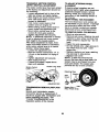
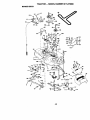
TO REPLACE MOWER BLADE
DRIVE BELT
With Parking Brake "Engaged"
The mower blade drive belt may be
replaced without tools. Park the tractor
on level surface. Engage parking brake.
BELT REMOVAL
-
• Remove mower from tractor (See "TO
REMOVE MOWER" in this section of
Jam Nut
this manual).
• Work belt off both mandrel pulleys and
idler pulleys.
• Pull belt away from mower.
BELT INSTALLATION
Operating
Arm
-
• Install new belt in reverse order of
removal.
• Make sure belt is in all pulley grooves
and inside all belt guides.
• Install mower in reverse order of
removal instructions.
Mandrel
Pulley Idler
Iley
TO ADJUST BRAKE
Your tractor is equipped with an adjustable brake system which is mounted on
the side of the transaxle.
If tractor requires more than six (6) feet
stopping distance at high speed in
highest gear, then brake must be
adjusted.
• Depress clutch/brake pedal and
engage parking brake.
• Measure distance between brake
operating arm and nut "A" on brake
rod.
• If distance is other than 1-9/16", loosen
jam nut and turn nut "A" until distance
becomes 1-9/16". Retighten jam nut
against nut "A".
• Road test tractor for proper stopping
distance as stated above. Readjust if
necessary. If stopping distance is still
greater than six (6) feet in highest
gear, further maintenance is necessary. Contact your nearest authorized
service center/department.
24
Do not touch this nut. If further brake
adjustment is necessary contact your
nearest authodzed service center/department
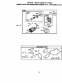
TO REPLACE MOTION DRIVE BELT
Park the tractor on level surface. Engage
parking brake. For assistance, there is a
belt installation guide decal on bottom
side of left footrest.
• Remove mower (See "TO REMOVE
MOWER" in this section of this
manual.)
• Remove belt from stationary idler and
clutching idler.
• Pull belt slack toward rear of tractor.
Carefully remove belt upwards from
transmission input pulley and over
cooling fan blades.
• Pull belt toward front of tractor and
remove downward from around
engine pulley.
• Install new belt by reversing above
procedure.
Engine Pulley--
_:_
Clutchingldler/
_1'
Input Pulley _
_
A
TRANSAXLE
MOTION CONTROL
LEVER NEUTRAL ADJUSTMENT
The motion control lever has been preset
at the factory and adjustment should not
be necessary.
• loosen adjustment bolt in front of the
right rear wheel, and lightly tighten.
• Start engine and move motion control
lever until tractor does not move
forward or backward.
• Hold motion control lever in that
-
position and turn engine off.
• While holding motion control lever in
place, loosen the adjustment bolt.
• Move motion control lever to the
neutral (N) (lock gate) position.
• Tighten adjustment bolt securely.
NOTE:
If additional clearance is needed
• Block up axle securely.
• Remove axle cover, retaining ring and
washers to allow wheel removal (rear
wheel contains a square key - Do not
lose).
• Repair tire and reassemble.
• On rear wheels only: align grooves in
rear wheel hub and axle. Insert
square key.
• Replace washers and snap retaining
ring securely in axle groove.
• Replace axle cover.
NOTE: To seal tire punctures and
prevent fiat tires due to slow leaks, tire
sealant may be purchased from your
local parts dealer. Tire sealant also
prevents tire dry rot and corrosion.
to get to adjustment bolt, move mower
deck height to the lowest position,
After above adjustment is made, if the
tractor still creeps forward or backward
while motion control lever is in neutral
position, follow these steps:
• Loosen the adjustment bolt.
• Move the motion control lever 1/4 to
1/2 inch in the direction it is trying to
creep.
• Tighten adjustment bolt securely.
• Start engine and test.
• If tractor still creeps, repeat abov e
steps until satisfied.
Motion Control
TO ADJUST STEERING WHEEL
ALIGNMENT
If steering wheel crossbars are not
horizontal (left to right) when wheels are
positioned straight forward, remove
steering wheel and reassemble per
instructions in the Assembly section of
this manual.
FRONT WHEEL TOE-IN/CAMBER
The front wheel toe-in and camber are
not adjustable on your tractor. If damage
has occurred to affect the front wheel
toe-in or camber, contact your nearest
authorized service center/department.
TO REMOVE WHEEL FOR REPAIRS
Neutral Lock Gate
Retaining Ring
Washer
Axle
Cover
Adjustment Bolt
TRANSMISSION
REMOVAl/REPLACE-
Square Key -_
(Rear Wheel Only)
MENT
Should your transmission require
removal for service or replacement, it
should be purged after reinstallation and
before operating the tractor. See
"PURGE TRANSMISSION" in the
Operation section of this manual.
25
TO START ENGINE WITH A WEAK
BATTERY
CAUTION: Lead-acid batteries
generate explosive gases: Keep sparks,
flame and smoking materials away from
batteries. Always wear eye protection
when around batteries.
If your battery is too weak to start the
engine, it should be recharged. (See
'BATTERY' in the MAINTENANCE
section of this manual).
If "jumper cables" are used for emergency starting, follow this procedure:
IMPORTANT: Your tractor is equipped
with a 12 volt negative grounded system.
The other vehicle must also be a 12 volt
negative grounded system. Do not use
your tractor battery to start other vehicles.
TO A-I-IACH JUMPER CABLES • Connect each end of the RED cable to
the POSITIVE (+) terminal of each
battery, taking care not to short against
chassis.
• Connect one end of the BLACK cable
to the NEGATIVE (-) terminal of fully
charged battery.
• Connect the other end of the BLACK
cable to good CHASSIS GROUND,
away from fuel tank and battery.
TO REMOVE CABLES, REVERSE
ORDER • BLACK cable first from chassis and
then from the fully charged battery.
• RED cable last from both batteries.
REPLACING
BATTERY
_lb CAUTION: Do not short battery
terminals by allowing a wrench or any
other object to contact both terminals at
the same time. Before connecting battery,
remove metal bracelets, wristwatch
bands,rings,etc.
Positive terminal must be connected first
to prevent sparking from accidental
grounding.
• Lift hood to raised position.
• Remove terminal guard.
• Disconnect BLACK battery cable then
RED battery cable and carefully
remove battery from tractor.
• Install new battery with terminals in
same position as old battery.
• Ralnstall terminal guard.
• First connect RED battery cable to
positive (+) battery terminal with hex
bolt and keps nut as shown. Tighten
securely.
• Connect BLACK grounding cable to
negative (-) battery terminal with
remaining hex bolt and keps nut.
Tighten securely
• Close terminal access doors.
• Close hood.
Hex Bolt
(Red)
Cable
Guard
=Positive" (+)
Negative (Black',
Cable
TO REPLACE HEADUGHT
BULB
• Raise hood.
• Pull bulb holder out of the hole in the
backside of the grill.
• Replace bulb in holder and push bulb
holder securely back into the hole in
the backside of the grill.
• Close hood.
"Negative" (-)
INTERLOCKS
26
AND RELAYS
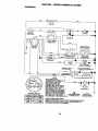
Loose or damaged wiring may cause
your tractor to run poorly, stop running, Ol
prevent it from starting.
• Check wiring. See electrical wiring
diagram in the Repair Parts section.
TO REPLACE FUSE
Replace with 15 amp automotive-type
plug-in fuse. The fuse holder is located
behind the dash.
TO ADJUST CHOKE CONTROL
TO REMOVE HOOD AND GRILL
ASSEMBLY
• Raise hood.
• Unsnap headlight wire connector.
• Stand in front of tractor. Grasp hood at
sides, tilt toward engine and lift off of
tractor.
• To replace, reverse above procedure.
ENGINE
Maintenance, repair, or replacement
the emission control devices and
of
systems, which are being done at the
customers expense, may be performed
by any non-road engine repair establishment or individual. Warranty repairs must
be performed by an authorized engine
manufacturer's
service outlet.
TO ADJUST THROI"rLE
CONTROL
CABLE
The throttle control has been preset at
the factory and adjustment should not be
necessary. Check adjustment as
described below before loosening cable,
If adjustment is necessary, proceed as
follows:
The choke control has been preset at the
factory and adjustment should not be
necessary. Check adjustment as
described below before loosening cable.
If adjustment is necessary, proceed as
follows:
• With engine not running, move choke
control (located on dash panel) to full
choke position.
• Loosen knob and remove cover
assembly from air cleaner.
• Choke should be closed. If it is not,
loosen casing clamp screw and move
choke cable until choke is completely
closed. Tighten casing clamp screw
securely.
• Replace air cleaner cover assembly
and tighten knob.
TO ADJUST CARBURETOR
The carburetor has been preset at the
factory and adjustment should not be
necessary. However, minor adjustment
may be required to compensate for
differences in fuel, temperature, altitude
or load. If the carburetor does need
adjustment, proceed as follows:
In general, turning the mixture screw In
(clockwise) decreases the supply of fuel
to the engine giving a leaner fuel/air
mixture. Turning the mixture screw out
(counterclockwise) increases the supply
of fuel to the engine giving a richer fuel/
air mixture.
IMPORTANT:
Damage to the
need[as and the seats in the carburetor
may result if screw is turned in too tight.
PREUMINARY SE]-I'ING -
Be sure you have a clean air filter,
and the throttle control cable and
choke are adjusted properly (see
above).
• With engine not running, move throttle
control lever to fast position.
• Check that swivel is against stop. If it is
not, loosen cable clamp screw and
pull cable back until swivel is against
stop. Tighten cable clamp screw
securely.
Clamp ,_w
....._vel
With engine off turn idle mixture
screw In (clockwise) closing it finger tight and then turn out (counterclockwise) 1-1/4 to 1-1/2 turns.
FINAL SETI'ING
_._
• Start engine and allow to warm for five
minutes. Make final adjustments with
engine running and shift/motion
control lever in neutral (N) position.
• With throttle control lever in slow
Cable
Governed Idle Spring
(Red or White)
-
Stop
position, hold throttle lever against idle
speed screw and adjust idle speed
screw to obtain 1300 to 1500 RPM.
27
• While still holding throttle lever against
idle speed screw, turn idle mixture
screw In (clockwise) until engine
begins to die and then turn out
(counterclockwise) until engine runs
rough. Turn screw to a point midway
between those two positions.
• Continue to hold throttle lever against
idle speed screw and adjust idle
speed screw to obtain 1200 RPM, if
the governed idle spring is red, or 900
RPM, if the governed idle spring is
white. Release throttle lever.
Clamp
Screw
Closed
O
Throttle
ACCELERATION TEST • Move throttle control lever from slow to
fast position. If engine hesitates or
dies, turn idle mixture screw out
(counterclockwise) 1/8 turn. Repeat
test and continue to adjust, if necessary, until engine accelerates
smoothly.
High speed stop is factory adjusted. Do
not adjust - damage may result.
IMPORTANT: Never tamper with the
engine governor, which is factory set for
proper engine speed. Overspeeding the
engine above the factory high speed
setting can be dangerous. If you think
the engine-governed high speed needs
adjusting, contact your nearest authorized service center/department, which
has proper equipment and experience to
make any necessary adjustments.
Screw
28
Idle Speed
Immediately prepare your tractor for
storage at the end of the season or if the
tractor will not be used for 30 days or
more.
_. CAUTION: Never store the tractor
w=thgasoline in the tank inside a
building where fumes may reach an
open flame or spark. Allow the engine to
cool before storing in any enclosure.
TRACTOR
Remove mower from tractor for winter
storage. When mower is to be stored for
a penod of time, clean it thoroughly,
remove all dirt, grease, leaves, etc. Store
in a clean, dry area.
• Clean entire tractor (See "CLEANING"
in the Maintenance section of this
manual).
• Inspect and replace belts, if necessary
(See belt replacement instructions in
the Service and Adjustments section of
this manual).
• Lubricate as shown in the Maintenance section of this manual.
• Be sure that all nuts, bolts and screws
are securely fastened. Inspect moving
parts for damage, breakage and wear.
Replace if necessary.
• Touch up all rusted or chipped paint
surfaces; sand lightly before painting.
ethanol or methanol) can attract moistu_
which leads to separation and formatio=
of acids during storage. Acidic gas can
damage the fuel system of an engine
while in storage.
• Drain the fuel tank.
• Start the engine and let it run untilthe
fuel lines and carburetor are empty.
• Never use engine or carburetor
cleaner products in the fuel tank or
permanent damage may occur,
• Use fresh fuel next season.
NOTE: Fuel stabilizer is an acceptable
alternative in minimizing the formation o,
fuel gum deposits during storage. Add
stabilizer to gasoline in fuel tank or
stori_ge container. Always follow the mi_
ratio found on stabilizer container. Run
engine at least 10 minutes after adding
stabilizer to allow the stabilizer to reach
the carburetor. Do not drain the gas tanF
and carburetor if using fuel stabilizer,
ENGINE OIL
Drain oil (with engine warm) and replac,
with clean engine oil. (See "ENGINE" in
the Maintenance section of this manual)
CYLINDER(S)
• Remove spark plug(s).
• Pour one ounce of oil through spark
plug hole(s) into cylinder(s)_
• Turn ignition key to "START" position
for a few seconds to distribute oil.
• Replace with new spark plug(s).
OTHER
BATTERY
• Fully charge the battery for storage,
• After a period of time in storage,
battery may require recharging.
• To help prevent corrosion and power
leakage during long pedods of
storage, battery cables should be
disconnected and battery cleaned
thoroughly (see "TO CLEAN BA'I-rERY
AND TERMINALS" in the Maintenance
section of this manual).
• After cleaning, leave cables disconnected and place cables where they
cannot come in contact with battery
terminals.
• If battery is removed from tractor for
storage, do not store battery directly on
concrete or damp surfaces.
• Do not store gasoline from one seaso_
to another.
• Replace your gasoline can ff your can
starts to rust. Rust and/or dirt in your
gasoline will cause problems..
• If possible, store your tractor indoors
and cover it to give protection from
dust and dirt.
• Cover your tractor with a suitable
protective cover that does not retain
moisture, Do not use plastic, Plastic
cannot breathe which allows condensation to form and will cause your
tractor to rust.
IMPORTANT: Never cover tractor while
engine and exhaust areas are still
warm.
ENGINE
FUEL SYSTEM
IMPORTANT: It is important to prevent
puUmdeposits from forming in essential
el system parts such as carburetor, fuel
filter, fuel hose, or tank dudng storage.
Also, experience indicates that alcohol
blended fuels called gasohol or using
29
TROUBLESHOOTING
PROBLEM
Will not start
CHART
CAUSE
CORRECTION
• Out of fuel.
• Engine not "CHOKED"
properly.
• Engine flooded.
• Bad spark plug.
• Dirty air filter.
• Dirty fuel filter.
• Water in fuel.
• Loose or damaged
wiring.
• Carburetor out of
adjustment.
• Engine valves out of
adjustment.
Hard to start
• Dirty air filter.
• Bad spark plug.
• Weak or dead battery.
• Dirty fuel filter.
• Stale or dirty fuel.
• Loose or damaged
wiring.
• Carburetor out of
adjustment.
• Engine valves out of
adjustment.
Engine will not turn
over
• Clutch/brake pedal not
depressed.
• Attachment clutch is
engaged.
• Weak or dead battery.
• Blown fuse.
• Corroded battery
terminals.
• Loose or damaged
wiring.
Faulty ignition switch.
Faulty solenoid or
starter.
• Faulty operator
presence switch(es).
Engine clicks but will
not start
• Weak or dead battery.
• Corroded battery
terminals.
3O
• Fill fuel tank.
• See "TO START ENGINE"
in Operation section.
• Wait several minutes
before attempting to start.
• Replace spark plug.
• Clean/replace air filter.
• Replace fuel filter.
• Drain fuel tank and
carburetor, refill tank with
fresh gasoline and replace
fuel filter.
• Check all wiring.
• See '3"0 Adjust Carburetor"
in Service Adjustments
section.
• Contact an authorized
service center/department.
• Clean/replace air filter.
• Replace spark plug.
• Recharge or replace
battery.
• Replace fuel filter.
• Drain fuel tank and refill with
fresh gasoline.
• Check all wiring.
• See "To Adjust Carburetor"
in Service Adjustments
section.
• Contact an authorized
service center/department.
• Depress clutch/brake
pedal.
• Disengage attachment
clutch.
• Recharge or replace
battery.
• Replace fuse.
• Clean battery terminals.
• Check all wiring.
• Check/replace ignition
switch.
• Check/replace solenoid or
starter.
• Contact an authorized
service center/department.
• Recharge or replace
battery.
• Clean battery terminals.
TROUBLESHOOTING
PROBLEM
CHART
CAUSE
Engine clicks but will
not-start (Cont'd)
Loss of power
CORRECTION
• Loose or damaged
wiring.
• Faulty solenoid or
starter.
• Check all wiring.
• Cutting too much
grass/too fast•
• Throttle in =CHOKE"
position.
• Build-up of grass,
leaves and trash
under mower.
• Dirty air filter.
• Low oil level/dirty oil.
• Faulty spark plug.
• Set in "Higher Cut" position/
reduce speed.
• Adjust throttle control.
• Dirty fuel filter.
• Stale or dirty fuel.
• Water in fuel.
• Spark plug wire loose.
• Dirty engine air screen/
I" fiDnS4/clogged
muffler.
• Loose or damaged
wiring.
• Carburetor out of
adjustment.
• Engine valves out of
adjustment.
Excessive
vibration
Engine continues
to run when operator
leaves seat with
attachment clutch
engaged
Poor cut - uneven
• Worn, bent or loose
blade.
• Bent blade mandrel.
• Loose/damaged part(s).
• Check/replace solenoid or
starter.
• Clean underside of mower
housing.
• Clean/replace air filter.
Check oil level/change oil.
Clean and regap or change
spark plug.
• Replace fuel filter.
• Drain fuel tank and refill
with fresh gasoline.
• Drain fuel tank and carbure
tor, refilltank with fresh
gasoline and replace fuel
filter.
• Connect and tighten spark
plug wire.
• Clean engine air screen/fins.
• Clean/replace muffler.
• Check all wiring.
• See "To Adjust Carburetor"
in Service Adjustments
section,
• Contact an authorized
servic e center/department
• Replace blade. "lighten
blade bolt.
• Replace blade mandrel.
• Tighten loose part(s).
Replace damaged parts.
• Faulty operator-safety
presence control
system.
• Check wiring, switches and
connections. If not corrected,
contact an authorized
service center/department
• Worn, bent or loose
blade.
• Mower deck not level
• Buildup ofgrass,
leaves, andtrash
under mower.
• Bent blade mandrel•
• Clogged mower deck
ventholas from buildup
• of grass, leaves, and
trash around mandrels.
Replace blade. Tighten
blade bolt.
• Level mower deck.
• Clean underside of mower
housing.
31
• Replace blade mandrel.
• Clean around mandrels to
open vent holes.
TROUBLESHOOTING
CHART
PROBLEM
Mower blades will not
rotate
Poor grass discharge
CAUSE
CORRECTION
• Obstruction in clutch
mechanism.
• Remove obstruction.
• Worn/damaged
drive belt.
• Replace
mower drive belt.
• Frozen idler pulley,
• Frozen blade mandrel.
• Replace
• Replace
idler pulley.
blade mandrel,
• Engine speed too slow.
• Place throttle control in
=FAST"position.
• Shift to slower speed.
• Allow grass to dry before
mowing.
• Level mower deck.
• Check tires for proper air
pressure.
• Replace/sharpen blade.
Tighten blade bolt.
• Clean underside of mower
housing.
mower
• Travel speed too fast.
• Wet grass.
• Mower deck not level.
• Low/uneven tire air
pressure,
• Worn, bent or loose blade.
• Buildup of grass,
leaves and trash under
mower.
• Mower drive belt worn.
• Blades improperly
installed.
• Improper blades used.
• Clogged mower deck
vent holes from buildup
of grass, leaves, and
trash around mandrels.
• Replace mower drive belt.
• Reinstall blades sharp edge
down.
• Replace with blades listed
in this manual.
• Clean around mandrels to
open vent holes.
Headlight(e)
not
working (if so
equipped)
•
•
•
•
Switch is =OFF".
Bulb(s) burned out.
Faulty light switch.
Loose or damaged
wiring.
• Blown fuse.
• Turn switch"ON".
• Replace bulb(s).
• Check/replace light switch.
• Check wiring and connec
tions.
• Replace fuse.
Battery will not charge
• Bad battery cell(s).
• Poor cable connections.
• Replace battery.
• Check/clean all connec
tions.
• Replace regulator.
• Faulty regulator (if so
equipped).
• Faulty alternator.
• Replace
alternator.
I
Loss of Drive
• Freewheel
control in
=disengaged"
position.
• Motion drive belt worn,
damaged or broken.
• Air trapped in transmission during shipment or
servicing.
Engine "backfires"
when turning engine
"OFF"
• Engine throttle control
not set at "SLOW"
position for 30 seconds
before stopping engine.
32
• Place freewheel control in
"engaged" position.
• Replace motion drive belt.
• Purge transmission.
Move throttle control to
=SLOW" position and allow
to idle for 30 seconds before
stopping engine.
TRACTOR - - MODEL NUMBER 917.270860
SCHEMATIC
BLACK
I
°
J (OPTIONAL)
wHiTe
I
J
O_O
'
FUSE'_5AMP.
I"-
.....
,i-
_
_
STARTER
_.....,
----'_
I
Bt_
SOLENOID
I
I_
SEATSWWCH
(NOTOCCUPIED)
IGNITION
t
8_OK
GROUNDING
CONNECTOR
eL_K
(CLUTCH
OFF)
•
(OPTIONAL)
K_K
(_
CHAROING
tGNmON
UNIT
_pt',J_R_M OUT PUT
SPARK
I
_
PLUG
L
GAP
[-"-_{2
PLUGS ON
TWIN CYI_ ENGINES)
_ VOLTS AO MIN, O 3_00 RpM
ORf_E
IGNmON SWITCH
NOTE
YOUR TRACTOR IS
EQUIPPED WITH A SPECIAL
ALTERNATOR SYSTEM.
THE LIGHTS ARE NOT
CONNECTED TO THE
BAI-FERY, BUT HAVE THEIR
OWN ELEC31:UCALSOURCE.
BECAUSE OF THIS, THE
HEADLIGHTS
BRIGHTNESS OF THE UGHTS
WILL CHANGE WITH ENGINE
SPEED. AT IDLE THE LIGHTS
WILL DIM. AS THE ENGINE IS
NON-REMOVABLE
REMOVABLE
SPEEDED UP, THE LIGHTS
CONNECTIONS
WILL BECOME THEIR BRIGHTEST. CONNECTIONS
WIRING INSULATED CUPS
NOTE: IF WIRING INSULATED CLIPS WERE REMOVED FOR
SERVICING OF UNIT, THEY SHOULD BE REPLACED TO
PROPERLY SECURE YOUR WIRING.
33
"_
TRACTOR - - MODEL NUMBER 917.270860
ELECTRICAL
I
I
I
I
41
I
I
I
I
16
I I
i
II
I
I I
_45
29
11
I
I
t
I
12
34
TRACTOR - - MODEL NUMBER 917.270860
ELECTRICAL
PART
NO.
NO.
1 163465
2 74760412
8 7603J
10 145211
11 150109
12 145769
16 153664
19 S'rD551125
20 73350400
21
166182
22 4152J
24
4799J
25
146148
26
166180
27
73510400
28
145491
29
121305X
30
140301
31
124211X
32
141226
33
109310X
40
16_o96
41
71110408
42
131563
43
168327
44 73640400
45
121433X
52
141940
55
17490508
70 166658
DESCRIPTION
Battery
Bolt,Hex 1/4-20 x 3/4
Tray, Battery
Bolt,BtrFront 1/4-20x7-1/2
Ho(ddownBatteryFront Mount
Nut, Push NylonBattery Front 1/4
Switc_ InterlockPush-In
Washer, Lock 1/4
NUt, Hex, Jam 1/4-20
Harness, LightSocket(w/4152J)
Light Bulb
Cable, Battery
Cable, Battery
Fuse
Nut Kel_ He)( 1/4-20 Unc
Cable, Ground
Switch, Seat
Switch, Ignition4 Position
Nut, Ignition
Cover, IgnitionSwitch
Key, Molded,Cra_tsman
Harness, Ignition
Bolt_,lkFin Hex 1/4-20 UNC x 1/2
Cover,Terminal
Solenoid
Nut Keps BIk He)( 1/4-20 UNC
AmmeterRectangular6 Amp
ProtectionWire Loop (HourMeter)
ScrewThdrol 5/16-18xl/2
Harness EngineB&S
NOTE: Allcomponentdimensionsgivenin U.S. inches
1 inch= 25.4 mm
35
TRACTOR - - MODEL NUMBER 917.270860
CHASSIS AND ENCLOSURES
28
12
53
31
14
3
74
3
36
TRACTOR - - MODEL NUMBER 917.270860
CHASSIS AND ENCLOSURES
KEY
NO.
1
2
3
4
5
9
10
11
12
13
14
17
18
20
23
25
26
28
29
30
31
37
38
39
51
52
53
54
55
57
58
60
64
74
140
142
143
144
145
PART
NO.
DESCRIPTION
166816
140356
Dmwbar
17060612
Screw 3/8-16 x 3/4
S'1_551025
Washer 13/32 x 3/4 x 16 Gauge
155272
BumperHood/Dash
165454)_313 Dash, Silkscrsened
_710
Bolt, Carriage 3/8-16x 1
155_7
Panel, Dash, LH
145660
Ct_pTmnsrmanGrilleP/t.
169118
Panel, Dash, RH
•
17490608
Screw, Thd., Roll. 3/8-16 x 1/2 Type "IF
144983X558 Hood Assem'oty
126e_SX
Bomber Hood
156437
Plate Mtg Battery FuelTank
124028X
Bushing,Snap, Nylon,Fuel Line
19131312
Washer 13/32 x 13/16 x 12 Gauge
S'TD541437
Locknut,Hex, with Insert 3/8-16 UNC
156725X558 Grille/LensAsm
155217X599 Lens, Grille
151267X558 Fer,.der/Footrast
139976
Bracket,Fender/Support
17490508
Borew, Thdrol. 5/16-18 x 1/2 TYT
139886
P'_otBracket Assembty, L.H,Mower, Rear
139887
Pivot Bracket Assembly, RH, Mower, Rear
Nut LockW/Insert 1/4 - 26 UNC
7380040O
19091416
• Washer 9/32 X 7/8 X 16 Ga.
1452O1
BracketGdlle Pickoff LH
161464
Screw, Hex Wshd #6-16x7/8
BracketGrillePickoff RH
14,._r,.o0_
STD552507 BoltFinHex 1/4 °20 UNC X.75
140547
Air Duct P/L 18HP B&S 0pp. T',,A
n
72140606
BoltRdhd Sqnk 3/8-16 UNC x 3/4
154798
DashLewerSTLT
STD541437
NutCrowniock3/8-16 UNC
158418
Bracket SuspensionFront
165867
Plate ReinforcementSTLT
154966
Bracket Swaybar Chassis
Bracket FootrestSTLT
154207
156524
Rod PivotChassis/Hood
NOTE: All componentdimensionsgiven in U.S. inches
1 ioch = 25.4 rnm
37
TRACTOR - - MODEL NUMBER 917.270860
GROUND DRIVE
52
22
27
84
55
77
105
38
TRACTOR - - MODEL NUMBER 917.270860
GROUND DRIVE
K]EY PART
NO.
NO.
1
......
2
3
8
10
14
16
142431
143995
165866
STD561210
10040400
_1431
18
STD523710
19
_1437
21
22
24
25
26
27
28
29
30
32
34
35
36
37
38
39
40
41
42
47
48
49
50
51
52
53
55
56
57
59
61
62
63
64
65
130564
145627
73350600
106888X
STD551037
STO561210
145204
124236X
130807
74760512
155071
120183X
19211616
1572t-I
131494
STD523727
4470J
165838
19131312
127783
154407
123205X
_715
STD541437
STD541431
105710)(
105709X
STD523712
140294
140312
17060612
8883R
140186
164975
$1_551143
DESCRIPTION
Transaxle(See Breakdown)
HydroGr 319-0650
Spring, Return, Brake
Pulley,Transaxle
Rod Shift Fender Adjust
PinCetter 1/8xl CAD
WasherLcokHvyHelical
Nut LockHex W/ins. 5/16-18
Unc
BoltFinHex 3/6-16Uncxl
Gr. 5
Nut LockHex WhNsh 3/8-16
Unc
Knob, Deluxe 1/2-13
Rod, Brake Hydro
Nut, HexJam 3/8-16Unc
Spring,Brake Rod
Washer
PinCotter 1i8x3/4CAD.
ROd,ParkingBrake
Cap, ParkingBrake
Bracket,Transaxle
BoltHexHd 5/16.18Uncx3/4
Shaft, FootPedal
Bearing,Nylon
Washer
Pin, Roll
Pulley, Idler, Flat
Bolt
Spacer, Split
Keeper, Belt Idler
Washer 13/32x13/16x12Ga.
Pulley, Idler,V-Groove
BellcrankClutch Gmd Dr'/STL
Retainer,Belt
Bolt
NutCrownlock 3/6-16UNC
NUt, Crownlock 5/16.18 Unc
Link, Clutch
Spdng, Return, Clutch
BoitHex 3/8-16x1-1/4
V-Belt, Ground Drive
Keeper, Center'Span
Screw 3/8-16x3/4
Cover, Pedal
PuLley,Engine
Bolt Hex 7/16-20 x 4 Gr. 5
Washer
KEY
NO.
PART
NO.
66
154778
70
134683
71
140158
72
19132012
73 156347
74 121199X
75 121749X
76 S'[0581075
77
123583X
78
121748X
81
165591
82 "165711
83
19171216
84
165815
89
164890X428
90
124346X
93 142564
94
140462
g5 167696
96 4497H
97
140469
96
102
103
104
105
116
145
146
147
150
151
156
157
158
159
160
161
162
163
164
165
166
168
169
73510600
14"_322
73940800
140156
71070516
7211C610
7449(3540
74490536
7449(To24
165850
19133210
166002
153236
165589
165494
19_92016
72140406
73680400
74780416
19091010
165623
166880
16549_
165580
DESCRIPTION
Keeper BettEngineHydro
Guide Be_RH Engine
Strap TorqueI.h Hydro 18/20"T
Washer 13/32 x 1.1/4 x 12 Ga.
StrapTorque Rh Hydro 0650
Spacer, Split
Washer 25/32 x 1-1/4x 16Ga.
E-Fling
Key, Square
Washer 25/32 x 1-5/8 x 16 C-=a.
Shaft Asm Cross Tapered 650 2q
Spring Torsion
Washer 17/32x3/4x 16Ga.
LinkTransaxle 0650 LT/Y'F/STL
Console, Shift
Nut Self.ThdWsh-hd 1/4 Zinc
Line Fuel Hydro 4"
Fan, Hydro 7"
Control BypassHydro
RetainerSpdng 1"Zinc!Cad
Keeper BoltRh Hydro 0750.
18/20"
Net Keps Hex 3/8-16Unc
Washer Bellvitle .501D x 1.50D
Net Has Jam Toplock 1/4-20 Ur_
Arm,Control Hydro
Screw Cap Hex 5/16 x 18 x 1
Bolt Can'. 3/8-16 x 1.25
Bolt Hex FIghd 5/16-18 Gr. 5
Bolt Hex Flghd 5/16.18 x 2-1/4
BoltHex Flghd 5/16-18 x 1-1/2
BushingBell.crankGrd Odve
Washer 13/32 x 2 x 10 Ga.
Washer Srrted5/161D x 1.125
Bolt Shoulder5/16-18 Unc - 2A
Bracket Shift Mount
HubTappered Range ShiftLt
Washer 29/32 x 1-1/4 x 16 Ga
Bolt Rdhd Sqnk 1/4-20 x 3/4 Gr.
NutCrownlockl/4-20 Uric
Bolt Hex Fin 1/4-20 Uncx 1 Gr.
Washer 5/8 x .281 x 10 Ga
Bracket Pivot Lever
Screw 5/16-18 x 5/8
BoltShoulder5/16-19 x .561
Plate FasteningLt
NOTE: Allcomponentdimensions given in U.S. inches
1 inch = 25.4 mm
39
TRACTOR - - MODEL NUMBER 917.270860
STEERINGASSEMBLY
t
i
i_I
_41
I
11_--*_.. d12
....----17
118
47
\
\
al
4O
TRACTOR - - MODEL NUMBER 917.270860
STEERING ASSEMBLY
KEY
NO.
1
2
3
4
5
6
7
8
9
10
11
13
15
17
18
19
22
23
25
26
27
28
29
30
32
36
37
38
39
40
41
42
43
44
46
47
51
54
6_
63
65
66
67
68
79
8O
PART
NO.
139768
154427
156483
157473
6266H
121748X
19272015
12000029
3366R
156438
STD551137
154779
_1000
156546
57079
161]_95
165857
165851
154406
126847X
136874
19131416
17060612
STD561210
130465
155O99
15292"/
139769
19133812
STD541537
100711L
145054X428
121749X
153720
121232)(
6855M
7380(_00
74780520
16-/902
74780616
15478Q
1544O4
74781044
154429
19132012
74950612
DESCRIPTION
SteedngWheel
FrontAxk3Aseem_y
SpindleAssembly,LH.
SpindleAssembly,R.H.
Bearing, Race, Thrust, Hardened
Washer 25/32 x 1-5/8 x 16 Gauge
Washer 27/32 x 1-1/4 x 16 Gauge
Ring, Klip
BeEu'i.ng,
.st_ng CoLumn
Link,
Drag
Washer, Lock
Spacer, Bearing, FrontAxle
NUt, Lock,Flange 5/8-11 UNC
Shaft Assembly,Steering
Washer, Thrust .515 x .750 x .033
Support, Shaft
Screw hex WshhdTorx
PittmanShaft Assembly
Bracket, Steering
Bushing,Link, Drag
Gear, Sector
Washer 13/32 x 7/8 x 16 Gauge
Screw 3/8-16 x 3/4
Pin
Rod, Tte
Bushing,Steering
Soraw "t-t"#t0-32 x 5 x 3/8 Flange
Insert,Steering Wheel
Washer 13/32 x 2-3/8 x 12 Gauge
Gripco Nut
Adaptor,SteeringWheel
Boot,Steering Dash PiL Mtl BIk
Washer 25/32 x 1-1/4 x 16 Gauge
ExtensionSteering Non-Adjust
Cap, Spindle
Fitting,Grease
NUtLockHx W_
5/16-18 UNC
BoltFin Hex 5/16-18 UNC x 1-1/4
WJt,Steering Assembly, Service
Belt Fin Hex 3/8-16 uric.x 1 Gr. 5
SpacerAx_
Bearing Arm Pittman
Belt Fin Hex 5/8-1 lunc x 2-3/4
Brace Axle
Washer 13/32 x 1-1/4 x 12 Ga
Bolt Hex Nylon3/8-16 x 3/4
NOTE: All componentdim.ensionsgiven in U.S. inches
1 inch = 25.4 mm
41
TRACTOR - - MODEL NUMBER 917.270860
ENGINE
3
14
13
0
i
81
I
17
32
34
i
39
L
•
\
I OPTIONAL
EQUIPMENT
Spark Arrester
I
42
23
TRACTOR - - MODEL NUMBER 917.270860
ENGINE
KEY
NO.
1
2
3
4
5
6
7
8
10
11
12
13
14
15
16
17
23
25
26
27
29
31
32
33
34
35
37
38
39
81
PART
NO.
162152
17720410
149723
144O69
144O68
138129
150176
145552
STD551125
STD522507
165287
13280336
1_
_1237
17490624
159e80
145996
739206OO
1529L>7
137180
157103
1616_6
123487X
106062X
1706_512
8543R
10_o7X
128861
DESCRIPTION
ControlThrot Paddle 32 22
Screw Hex Thd Cut 1/4-20x5/8 T
Engine(See Breakdown)BriggsModel No. 461707-0145-E1
MufflerExhaust
Exhaust Asm. L.elt "
ExhaustAsm. Right
ClampTube Double Engine
Bolt5/16 - 18 UNC X 3/4 WiSems
Heat Shield t.t
Washer Lock Hvy, Helical 1/4
Bolt Fin Hex 1/4-20 x 3/4
Gasket Muffler
NipplePipe 4-1/2"
ElbowStd 90 Degree 3/8-18 Npt
Washer Lock ExtTooth3/8
ScrewTl_drot3/8-16xl -1/2 Tytt
ShieldBrowning,_Debris
Guard
Cor_ol Choke
Nut Keps 3/8-24 Unf
Screw"1-1"
#10-32 x 5 x 3/8 Flange
ArrestorSpark
Tank Fuel 3 50 Rear
Cap FuelGuage STLT
ClampHose BIk
Spacer Pad
Screw 5/16-18 x 3/4
LineFuel
PlugOil Drain (See EngineBreakdown
Pad Idler 1,75 x .75 x .06
Nut, Flange 1/4-20 Starter Nut
NOTE: Allcomponentdimensionsgiven in U.S, inches
1 inch= 25.4 mm
43
TRACTOR - - MODEL NUMBER 917.270860
SEAT ASSEMBLY
K]EY PART
NO.
1
2
3
4
5
6
7
8
9
!0
11
12
NO.
DESCRIPTION
140123
140551
74760616
19131610
145OO6
_1437
124181X
17060616
19131614
155925
166369
121246)(
Seat 34,50 BIk_k Craftsman
Bracket Pnt PivotSeat (blk)
BoltFin Hex 3/8-16unc X 1
Washer 13/32 X 3/4 X 10Ga
Clip PushInHinged
Nut Hex Lockw/Ins 3/8-16 Uric
SpringSeat Cprsn2 250 BIk Zi
Screw 3,.'8-16X1-1/2
Washer 13/32 X 1 X 14 Ga
Pan Pnt Seat (blk)
I<zx_ Seat
BracketPnt MountingSwitch
KEY
PART
NO.
NO.
13
14
15
16
17
21
22
24
25
121248X
72060412
134300
12125QX
123971_
153236
$3"ITo41431
19171912
127018X
DESCRIPTION
BushingSnap BIk Ny150 Id
BoltRdhdSht Nk 1/4-20xl -1/2
SpacerSprit28 X g6 Zinc
Sprklg Cprsn I 2-/Blk Pnt
NutLock 1/4 LgeFig Gr 5 Zinc
Bolt Shoulder5/16-18 Unc-2A
Nut Hex Lockw/Ins 5/16-t8
Washer 17/32 X 1-3/16 X 12 Ga.
BoltShoulder5]16-18 X 62
NOTE: All component dimensionsgiven in U.S. inches
1 inch = 25.4 mm
44
TRACTOR - - MODEL NUMBER 917.270860
DECALS
7
2
3
1
4
11
2
9
2O
14
13
14
15
KL=Y PART
NO.
NO.
1
2
3
4
6
156439
163205
163200
163202
133644
7
9
11
169637
163204
156811
13
146046
KEY
NO.
DESCRIPTION
Decal FenderDanger Sears
OecaJFend AutoSears Gold
Decal Hood Rh _
Decal Hood Lh Craftsman
Decal Malnt Customer
Sears Don]
Decal _rne_
Srs
Decal FenderCraftsmanGold
DecalFanderSTLTH Oper
Inst EiS
Decal V-belt Dr Sch TraotorE
14
15
19
20
22
- ----.
--
KEY
NO.
WHEELS & TIRES
PART
NO.
DESCRIPTION
166_'_7
1603_6
138047
166887
14_516
16_10
138311
154515
154516
169907
169908
Decal Dash Panel
Decal MowerDrive Schematic
Decal, BatteryDiehard Sears
Decal Deck Mower EZ3
Decal Battery
Decal By Pass Lt Hydro
Decal LiftHandte
Pad FootrestLh STLT •
Pad FootrestRh STLT
Manual,Owner's (Englbh)
Manual,Owner's (Spanish)
PART
NO,
DESCRIPTION
1
2
3
4
59192
65139
106222)(
59904
5
6
106732X427
2-/8H
7
2O40H
4,10
Valve Cap,"13m
Stem, Valve
Tire, Front
,
Tube, Fn_nt'_m
_lnotProvided, Service Item
ly)
Rim,Front
Fitting, Grease (FrontWheel
Onty)
11
Bearing,Range (FrontWheel
Only)
8
9
10
106108)(427
1_o(_2X
71523
11
--
104757X
144334
Rim, Rear
Tire, Rear
Tube, P,car_re
(Not Provided,Service Item
Only)
Cap, Axle
Sealant, Tire (10 oz. Tube)
NOTE: Allcomponentdimensionsgiven in U.S. inches
1 inch= 25.4 mm
45
TRACTOR - - MODEL NUMBER 917.270860
LIFT ASSEMBLY
27
25 24
7
41
iI •
!
s
5
49
38
30
3
13
6
6
5
4
13
13
2O
32
19
32
46
TRACTOR - - MODEL NUMBER 917.270860
LIFTASSEMBLY
NO.
1
2
3
4
5
6
7
8
11
12
13
15
16
17
16
19
20
23
24
25
26
27
28
29
30
31
32
36
37
38
40
41
49
50
PART
NO.
DESCRIPTION
159460
159471
1G5767X
12000002
19211621
120183X
125631X
122365X
139865
139866
_4008
127218
7'33.50800
130171
_
139868
163552
110807X
19131016
2876H
76020308
126971X
73350600
138057
1,50"233
1403(_
73540600
155097
123935X
17490512
19112410
155098
145212
110452X
Lift Lever InnerWire Asm.
Shaft Asm. Lift
Pin Groove
ERing
Washer 21/32 x 1 x 21 Ga.
BearingNyleng
Gdp Handle Ruted,
ButtonPlunger Read
LinkAsm Uft L.H.
Link Asm LiftR.H.
RetainerSpring
LinkFront
Nut Jam Hex t/2-13 Uno
TrunnionBIkZinc
Nut LockW/Wsh 1/2-13 Uric
Arm SuspensionMower
RetainerSpdng
Nut, Special
Washer 13/32 x 5/8 x 16 Ga.
Spnng
Pin, Cotter 3/32 x 1/2
Rod, Adjust Life
Nut, Hex Jam 3/8-16 UNC
Knob, infiniteHeight Admustment
Trunnion,Inf. Height
Bearing, Pvt. Lift.Spherical
Nut Crownleck3/8-24
Pointer Height Indicator
Plug Hole BIk 1.485/1.515 Dia
Screw Thdrol 5/16-1B x 3/4
Washer 11/82 x 1-1/2 x 10 Ga
IndicatorHeight Stlt
Nut, Hex Flange Lock
Nut, Push Phos. &-Oil
NOTE; ANcomponentdimensk)nsgiven in U.S. inches
1 inch= 25.4 mm
47
TRACTOR
- - MODEL NUMBER
917.270860
MOWERDECK
+m' ._C./
_"
40
36
153
1_4
159 "--.,_
>21
21
22
3 24
25
27
48
TRACTOR - - MODEL NUMBER 917.270860
MOWER DECK
KEY
NO.
PART
NO.
I
2
3
165892
S'FD533107
138017
4
5
6
8
9
10
1!
12
13
16548O
STD624006
130832
850857
STD551137
140296
134149
1298_5
137645
14 128774
15 110485X
16 140329
18 72140505
19 132827
20
159770
21
STD541431
22
134753
23
131267
24
105304X
25
123713)<
26
110452X
27
130968
28
19111016
29 131491
30
157722
31
129963
32
153535
33
137266
34 STD533717
35
133835
36
1314,94
37
19131316
40 STD541437
44
14O068
45 STD624003
46 137729
48 133944
49 155066
50 131340
51 ST[To41410
52 13.9888
53
131845
54
133943
55
155046
56
165723
59 141043
67 149846
DESCRIPTION
MowerHousing
Belt
Bracket Assembly,Sway Bar,
Front
BrasketSway Bar 38/42"
RetainerSpdng
Arm, S,JSpeosic_,Rear
Belt, Hex 3/8-24 x 1.25 Gr. 8
Washer, Lock
Washer, Hardened
Blade, Mulching
Beedng, Ball
Shaft Assembly,Mandrel,
Vented (Incl. Key Number6)
Housing,Mandrel, Vented
Bearing, Ball, Mandrel
stripper, Vented Mower Deck
Bolt, Carriage 5/16.-18x 5/8
Belt, Shoulder
Baffle, Vortex
Nut, Cmwnlock5/16-18UNC
Stiffener Bracket
Bracket, Deflector
Cap, Sleeve
Spring,Torsion,Deltector .
Nut, Push
Shield, Deflector
Washer 11/32 x 5/8 x 16 Ga.
Rod, Hinge
ScrewThdrolRollingWsh Hd
Washer, Spacer
Pulley,Mandrel
Nut, Toplock,Flanged
Bolt
Feelner,ChdstmssTree
Pulley, Idler, Flat
Washer 13/32 x 13/16 x 16 Ga.
Nut, Crownlock3/8-16 UNC
Guard, Mandrel, L.H.
Retainer
Screw, Thd. Roll 1/4-20 x 5/8
Washer, Hardened
RollarAssembly,Cam Fctk_ver
Belt, Shoulder#10-24 Grade 5
Locknut
Bo4t,Shoulder5/16-18 UNC
Arm Assembly,Pad, Brake
Washer, Hardened
Arm, Idler
Spacer, Retainer
Guard, Tuv Idler (94)
Knob CustomOval
KEY
NO.
PART
NO.
68
92
144959
STD541437
101
102
103
104
105
106
111
112
113
114
115
116
117
118
119
121
128
129
136420
71161010
19061216
STD551110
16079_
2029J
155107
155198
17060512
73510500
72110504
48981-1
165746
7"3930600
19121414
143723
153390
19131312
130
S'T'D523710
131
142
143
144
145
146
147
148
149
150
151
152
153
154
155
156
157
158
159
S'113533710
165890
157109
158634
165888
165891
131335
169(P-2
165898
19091216
169670
169676
169674
169675
169671
169672
169669
17720410
_717
- -
130794
--
169583
DESCRIPTION
_Belt
Locknut,Hex W/Wsh 3/6-16
UNC
Cover Mulching42" Black
Screw Truss Hd Phil10-24 x5/8
Washer #10
Washer Lock
Latch Asm Bagger
Nut Weld
Bracket Gauge, Wheel LH
Bracket,Gauge, Wheel RH
SCrew 5/16-18 x 3/4
NUt, Hex Keps 5/16-18 UNC
Belt, Carriage 5/16 UNC x 1/2
Belt, Shoulder
Wheel, Gauge
NUt,Crownlock 3/6-16
Washer 13/32 x 7/8 x 14 Ge.
Bracket
Washer Felt
Washer 13/32 x 13/16 x 12
Ga.
Bolt, Fin Hex 3/8-16 UNC x 1
Gr. 5
Bolt Rdh.dSqnk 3/8-16 UNC x 1
Arm SpdngBrake Mower
BracketArm Idler 42"
Keeper Belt42" Clutch Cable
Pulley Idler Rat
Belt Carraige Idler
SpringExtension
spdng Retum Idler
Retainer SpdngYdlGw Zinc
Washer 9/32 x 3/4 x 16 Ga.
Bracket Clutch
Cabla Clutch42"
Washer fiat 3/8" Type B
SpringRetainer
Spdng RetentionLever
Spacer
Rod Clutch
.
Screw Hex Thd CUt 1/4-20 x 5/8
Bolt Rdhd Sqn 3/8-16 Unc x 13/4
MandrelAssembly(Includes
Key Numbers 6-16, 12-15, 31
and32)
Mower Deck,Complete (Std
deck- order separately muloher
plate componentskey nos, 101106)
NOTE: Allcomponentdimensionsgiven in U.S.inchss
1 inch = 25.4 mm
49
TRACTOR - - MODEL NUMBER 917.270860
HYDRO GEAR TRANSAXLE . . MODEL NUMBER 319-0650
58
34
139
18
28
91 \
26
23
9O
19
53
52
14
91
9OO
35
5O
TRACTOR - - MODEL NUMBER 917.270860
HYDROGEARTRANSAXLE- - MODELNUMBER319-0650
KEY
PART
NO.
NO.
DESCRIPlr'ION
142960
142_1
142932
1429_8
142933
142884
1429G5
150771
142937
1429(38
1429G9
142940
142941
150772
150773
142944
142945
142946
150774
142948
142949
142950
150787
1_1
142952
142g53
142954
142955
150777
150778
142_68
Housing,Lower
Assembly,Upper Housing
Seal, Up
Ring,Wire Retaining
Ring, Retaining
Bearing, Shaft Ball
Bearing,Cradle
Baaring, Thrust 30x52x13
Swashplate,Variable
Block,Cylinder Assembly
Ann, Trunnion
Seal, Lip
Guide, Slot
Shaft, Motor
Baadng, Thrust 42x68x16
Block,Cylinder Assembly
Seal, Lip 10x25x7
Actuator, Bypass
Center Section Assembly Kit
Seal, Lip 26 x 42 x 8
Ring, Retaining
Washer 26 x 35 x 1
Plate, Bypass
Oil FilterElement
Ann, Bypass
Ring, Retaining
Arm,Actuating
Pin, Actuating
Bolt 5/16-24 x 1-3/4
Locknut,Hex 5/16-24 UNJC
Brake RotoriStatorWit
1
2
3
4
5
6
7
8
9
13
14
15
17
18
19
23
24
25
26
27
28
29
30
34
35
36
37
38
39
40
41
KEY
PART
NO.
NO.
DESCRIPTION
142884
150_9
142991
142961
142963
142964
14_65
142966
142967
142920
142969
144610
142971
150806
142973
142974
142975
142976
142977
142978
142917
142916
142980
144607
144608
150775
150776
150071
Washer 7/16 x 7/8 x .060
DifferentialAssembly
Washer 3/4 x1.5 x .13
Seal .75 x 1.25 x .250
Shaft, Input
Bolt 1/4-20 x 1.38
Pin .50D x .43 ID x .750
Arm,Control
Puck,Dampener
Bat Screw
Spdng
Stud 5/16-24
Jackshaft Assembly
Jackshaft
Screw,Cap
Washer 7/16 x 1 x 1/2
SleeveBaaring
Seal, Wiper
Spring, Block
Washer, BlockThrust
Cap, VentAasembly Frtting,O-Ring Assembly
Spacer
Nut, Castle 5/16-24
Pin, Cotter
Spring,Compression
Not, Hex 5/16-24
Trensaxle Complete
43
44
52
53
56
58
._
62
88
64
68
69
83
85
88
89
90
91
92
88
113
114
119
134
135
139
140
900
NOTE: Allcomponentdimensionsgiven in U,S. inches
1 inch -- 25.4 mm
51
TRACTOR - - MODEL NUMBER 917.270860
BRIGGS & STRATTON ENGINE-MODEL NUMBER 461707, TYPE NUMBER 0146-EI
634 ;
552A
552
4040
1095 VALVE OVERHAUL
GASKET SET
12191 61SA_I
1019 LABEL KIT
I
r
1058 OWNER'S MANUAL
I
m
_lr REQUIRES SPECIAL TOOLS
TO INSTALL
SEE REPAIR
INSTRUCTION
MANUAL
52
TRACTOR - - MODEL NUMBER 917.270860
BRIGGS & STRATTON ENGINE-MODEL NUMBER 461707, TYPE NUMBER 0145-E1
51 _
122 1
50 _
304
51A
865
205_
_4A o
202 _
212 _
267 t
203_
305_
307
865A
447
57__
861 PUMP REPAIR KIT
306A
425
307_
I
1..21CARBURETOR KIT
]
9681
_J7_
2say
,,_1138 11_S_'1
44S
Es21r
m ,1,,i}l_T _1
I 592e
I
-k REQUIRESSPECIALTOOLS
TO INSTAL1 SEEREPAIR
INSTRUC_ONMANUAL
9719
859
391 _
267_
1036 LABEL KIT-EMISSION
J
53
TRACTOR - - MODEL NUMBER 917.270860
BRIGGS
& STRATrON
ENGINE.MODEL
NUMBER
461707,
TYPE NUMBER
0145-E
802
513
783
I
i051
697
y
803
797 @
544
801
358 GASKET SET
20@
54
TRACTOR
- - MODEL NUMBER
BRIGGS & STRATTON ENGINE-MODEL
KEY
NO.
1
2
3
4
5
5A
7
7A
8
9
10
t0A
11
13
15
16
19
2O
23
24
25
26
27
28
29
32
33
34
35
36
4O
41
42
46
46
47
48
50
51
51A
53
54
73
75
78
91
PART
NO.
4.98583
399265
91086
4933O4
214517
214518
271867
271868
495754
27803
94382
94380
280_5
27339O
271188
271189
94565
94239
69O666
399264
291675
491180
222698
49918O
499181
4.99182
499183
499184
499285
4_186
499187
263129
498319
49832O
4.98314
496541
95017
39042O
494.553
691302
26828
2215_6
29226O
4.94.553
261368
214487
3_H15
4.98542
213290
271412
93970
932O8
691438
222511
_I 134
693483
917.270860
NUMBER 461707, TYPE NUMBER 0146.E1
DESCRIPTION
K]EY
NO.
CylinderAssembly
Bushing/SealWJt
_r SeaJ_)it
Sump-Engine
Head-Cylinder#1
Head-Cylinder#2
GasketoCylinderHead #1
Gasket-CylinderHead #2
Breather,Assembly(Cylinder#1)
Gasket-Breather
Screw (BreatherAssemb/y)
Screw (BreatherCover)
Tube-Bmether
-k Gasket-Crankcase (.015" Thick,
Std.)
_k Geaket-Crankcase (.005" Thick)
.k Gasket-Crankcase (.009" Thick)
Screw (CylinderHead)
Plug40ilDrain
Crankshaft
Bushing
Seal-Oil
Flywheel
Key-F'_
PistonAssembly (Standard)
PistonAssembly (,010 =O.S.)
PistonAssembly (.020" O.S.)
Piston Assembty(.030" O.S.)
Ring Set, Piston(Standard)
Ring Set, Pistea (,010 "O.S.)
Ring Set, Piston(,020 "O.S.)
Ring Set, Piston (,030 "O.S.)
Lock-PistonPin
Pin Assembly, Piston (Std.)
Pin Assembly-Piston(.005"
O.S.)
Rod-Connecting(Standard)
Rod-Connecting(.020 U.S.)
Screw (ConnectingRod)
Va,'ve-F_._aust (t_dude(e):
Keeper-valve (Ref. No. 42))
Valve-Intake
Spring-Valve(Intake)
Sp,nO-Vak_ (Exhaust)
Retainar-Valve(Exhaust)
Retainer-Valve(E_aust)
Keaper-Vstve
Tappet-Vah_
CamshaR
Slinger-Oit
Short Block
Manifold-Intake
Gasketolntake
•_€ Gasket-Intake
Screw (Carburetor)
Screw (Intake Mantfok_
Screen-Rotating
Washer (Flywheel)
Screw (FlywheelFan)
Body Aasembly-Uppe_
95
97
98
102
104
105
107
108
109
1!7
121
122
125
130
133
146
147
161
163
177
187
197
202
203
205
209
2!1
212
215
219
220
222
_7
235
240
244
258
267
278
297
304
3O5
306
306A
307
309
310
311
332
333
334
337
356
358
383
386
391
392
55
PART
NO.
690718
693485
2O7_
693509
693506
692078
693482
6_3505
693498
693538
69G500
491539
281411
_3479
693504
693512
94196
693508
496599
271411
271170
299146
DESCRIPTION
Screw ('l'hrottleValve)
Shaft-Threttle
I_t-ldle Speed
• Gasket-CarburetorBody
• Pin-_Hinge
• Valve-FleatNeedle
BodyAsasmbly-Lower
Valve-Choke
Shaft-Choke
Jet-Main
Jet-Main(HighAltitude)
CarburetorI_
Spacer
Carburetcr
Valve-Throttle
Roar-Carburetor
Key-_ming
Jet-Pilot
Base-AirCleaner
tk C-_skst-Air_er
_r SeaJ-O-Ring
Line-Fuel(Cutto Reduired
Length)
95063
Screw (Back Plate)
262683
Link-MechanicalGovernor
28(_97
Crank-Ball
93971
Screw (BellCrank)
262352
Sprig-Governor
261563
Swing-Governor
69_985
Link-Throttle
224816
Guide-Air
394348
Ge,_-Govemor
222773
Washer-Thruet(GovernorGear)
491282
Bracket-Control
491297
Lever-Governor
0o4995
Sh_d-Fu_ Spray
394358
Filter-Fuel
230318
Connector-Hose(Pulse Line)
_
Screw(EngineSump)
93897
Screw (cosk_O
C_amp)
94942
Washer (GovernorLever)
94289
Nut-Wing(AirFilterRetainer)
691390
Housir_
69O960
Screw(Bower _)
222846
Shield-Cylinder
223734
Shield-Cylinder
94930
Screw (CylinderShield)
497596
Moter-Starter
94003
Bolt (StarterMotor)
497608
Brush Set
230674
Nut(Flywheel)
394891
_e-Magnelo
94731
Sclew (MagnetoArmature)
802592
Plug-Spark
4947_
Wire-Stop
4,95868
Gasket Bat
89838
Wrench-SparkPlug
693490
•+ Gasket-Pump
69_487
Body-Pump
fl_G491 e+ Slmng-Pumpt:_aphragm
TRACTOR
- - MODEL NUMBER
BRIGGS & STRATTON ENGINE-MODEL
KEY
NO.
PART
NO.
404
423
425
432
433
434
435
441
445
447
449
474
482
510
513
523
525
527
535
544
552
552A
562
569
572
573
592
601
615
615A
616
634
634A
635
637
643
689
697
725
726
741
783
223882
94674
94823
6934_Z
693489
60349_
693494
222875
394019
93343
94882
93474
93621
497606
39800_
494947
495348
223167
272490
97603
262332
262331
93853
272645
222892
491304
92278
95162
94296
93898
491530
491287
271013
66538
693510
496700
262337
93585
280866
91362
262989
693059
797
797A
94010
69_167
Nut (StarterTerminal)
Nut (StarterTerminal)
802
803
807
497607
497604
693511
_
Housing-Starter
Spacer
917.270860
NUMBER 461707, TYPE NUMBER 0145-E
DESCRIPTION
Washer (GovernorCrank)
Screw f,Air Cleaner Base)
Screw (AirCleaner _
0+ Cap-Spring
•+ Diaphragm-FuelPump
Cover-Diaphragm
Scow (Diaph.ragm
Cover)
Bracket-OilFill
Filter-Air
Screw (Air Guide Cover)
Screw (Oil FillBracket)
Alternator
Screw (Alternator)
Drive-Starter
Clutch-Drive
Dipstick
Tut_=-oilFill
Clamp-Tube
Filter-Air
Armature-Starter
Bushing(GovernorCrank)
Bushing(Governer Crank)
Bolt-Carriage (GovernorLever)
_ Gasket-Base
Cover-Breather(Cylinder#2)
Plate-Back
Nut (Governer Lever)
ClampHose
Retainer (GovernorCrank)
Retainer-GovemorShaft
Crank_ovemor
,A-SeaJ-Govemor Shaft
Washer-Foem
Boot-SparkRug
Washer-Se_d
Retainar-AirFilter
Spdng-Fdc_on
Screw (DriveCap)
Shield-Heat
GasFP_'_j
Ge_-_ming
Gear-Starter
KEY
NO.
PART
NO.
822
847
851
859
861
865
B65A
868
868A
869
870
871
693497
495715
493880
6g_188
39_397
224774
224775
497656
273312
261463
262_4
=361961
231218
393456
495901
3_815
877
881
918
934
955
968
971
1005
1006
1019
1036
1051
1058
1081
1090
1095
1125
1132
1136
1137
1138
....
_
•
e
+
DESCRIPTION
Washer-Seal ('f'hrottleShaft)
DipstickKubeAssem_y
Terminal_3ab_e
I_- Diaphragm-FuelPump
Kit-FuelPump
Cover-AirGuide
Cover-A_Guide
Seal-Valve
Seal-Valve
Seat-Valve (Intake)
Seat-Valve (Exhaust)
Bushing-Guide(Exhaust)
Bushing-Guide (Intake)
Wire-Alternator
Rate-Cover
Hose-Vacuum(Cylinder-To-Irapulse Pump)(Cutto Required
Length)
94627
Screw (Fan Retainer)
693513
_etor
_5008
Cover*AirCleaner
805540
Screw (Upper BodyTo Lower
Body)
498157
Fan-Flywheal
224901
Retainer-Fan
496726
Label Kit
499382
Label I_rt.EmissJon
263080
Ring-Retaining
273688
Owner'sManual
280860
.JrSeal-O-Ring
497605
Retainer-Brush
4.96047
Gasket Sat-Valve Overhaul
94724
Sc_,w (Cover Rate)
94675
Screw (OilSlinger)
94297
Screw (Governor,Con_ol Rod)
220680
Washer (Governer,ControlRod)
94298
Nut (Governor,ControlRod
460707-0145-E1ReplasementEngine
Included in Gasket Set, Ref Number358.
Includedin Carburetor1_3t.
Ref Number 121.
Includedin Value Overhaul tot, Ref Number
1095.
Included in Fuel PumpI_0t,Ref Number 861
*
NOTE: Allcomponent dimensionsgiven in U.8. inches
1 inch = 25.4 mm
56
57
SUGGESTED
I
GUIDE FOR SIGHTING SLOPES FOR SAFE OPERATION
ONLY RIDE UP AND DOWN HILL,
NOT ACROSS HILL
"
SIGHTING
15° MAX.
_
.Jk
Operate your Tractor up end down the face of elopes (not
greater than 15 ), never across the face. Make turns gradually to prevent tipping or loss of control. Exercise extreme
direction on slopss.
For in-home major brand repair service:
Call 24 hoursa day, 7 days a week
1-800-4-MY-HOME
s" (1-800-469-4663)
Para pedir servicio de reparaci6n a domicilio
1-800-676-5811
In Canada for all your service and parts needs call
Au Canada pour tout le service ou les pi_ces
1-800-665-4455
For the repair or replacement parts you need:
Call 6 am - 11 pm CST, 7 days a week
PartsDirectsM
1-800-366-PART
(1-800-366-7278)
Para ordenar piezas con entrega a domicilio
1-800-659-7084
For the location of a Sears Parts and Repair Center
in your area:
Call 24 hours a day, 7 days a week
1-800-488-1222
For information on purchasing a Sears Maintenance
Agreement or to inquire about an existing Agreement:
Call 9 am - 5 pro, Monday - Saturday
1-800-827-6655
IHome Central'MJ
I 169907
Rev. 1 7,6.99
TR
Printed in U.S.A.