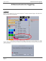
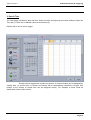
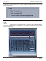
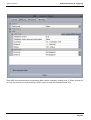
1
Cyber Control 2
DT
USER MANUAL
ROBE lighting s.r.o.
Czech republic
www.robe.cz
Table of contents
I Before We Start
1. What's New to Suite 2
2. The Cyber Control Package
3. Software & Hardware Installation
4. Fixture Profiles
II Quick Start
1. Creating your first show
2. Creating your first Scene
3. Editing a scene with EasyStep
4. Editing a Scene with EasyTime
III Programming
1. Show Structure
2. Creating The MASTER Page
3. Creating Cycles
4. Button Editor
5. Arranging Buttons
6. Button Dials
7. Scene Fading
8. Palettes
9. Palette Types (advanced)
IV EasyTime Effects
1
2
10
13
14
17
16
21
23
27
31
30
31
33
36
39
42
46
48
50
55
1. ConstantLevel
2. Gradient
3. Curve
4. Color
5. X/Y
6. Matrix
7. Picture
8. Gif
9. Video
10. Text
11. Color Manager
12. EasyTime Phasing
54
55
56
57
58
59
60
60
61
62
63
64
V Dealing with Fixtures
67
1. Groups
2. Rects
66
68
3. Live Control with Groups
4. Advanced Positioning
5. Advanced Patching
6. Multiple Universes
7. Printing a Patch
VI External Control & Triggering
1. Keyboard
2. Date & Time
3. MIDI
4. DMX
5. Interface Ports
6. MIDI Time Code (MTC)
7. Audio
8. OLED Keypad
VII Other Features
1. Access Privileges
2. Favourites
3. Multimedia
4. Stand Alone
VIII Easy Show
1. Getting Started
2. Creating Timelines Manually
3. Timeline Options
4. Other Options
5. Triggering
6. Synchronization Options
IX Other Software
1. Console Editor
2. 3D Visualiser
3. Scan Library Editor
70
72
73
76
77
79
78
79
81
85
87
89
91
93
96
95
96
98
99
104
103
106
107
108
109
110
113
112
114
116
Cyber Control 2
I Before We Start
I Before We Start
Welcome
Welcome to Cyber Control 2! You are probably eager to
get straight on with your programming and see what Suite 2 is capable of doing so we have made the
first two chapters short and simple. The aim of the first chapter is to prepare you for using the software.
The second heading explains the foundations of the software. If you are completely new to Cyber
Control or lighting programming, the first two headings should be enough to get you started.
Checklist
Before starting, make sure you have all the required tools. You should have a package with:
-USB-DMX interface
-PC or laptop computer running Microsoft Windows XP, Vista or Seven (if you are using a 64 bit
operating system, check the hardware documentation to make sure the interface supprts 64 bit)
-USB cable
-Software installation CD
I
Page 1
Cyber Control 2
1. What's New to Suite 2
This chapter is for Cyber Control 1 users and outlines the new features in Suite 2
Page 2
I Before We Start
Cyber Control 2
I Before We Start
The first thing you will notice is that the menus have been replaced with a ribbon bar
All information is now saved in a .shw show file. Suite 1 show files (.ssh) can be
imported.
Page 3
Cyber Control 2
I Before We Start
The page panels have been re-designed to be more ergonomic and to save space.
Buttons can now be re-arranged manually by ctrl+ right clicking and dragging
New button compression types such as pop-up toolboxes help save screen space.
Page 4
Cyber Control 2
I Before We Start
Shift+clicking a button brings up a small toolbox where button functions can be modified.
Faders have been changed to rotary dials. These dials save space and allow a higher definition. They
can be adjusted just as easily as faders by selecting the dial and moving the mouse up and down.
Date and time triggering of buttons now uses a graphical calendar.
Page 5
Cyber Control 2
I Before We Start
Direct access to easy show functions is now possible without having to rename buttons.
The patch manager has been changed. Fixtures can now be patched using a grid view.
Page 6
Cyber Control 2
I Before We Start
The button editor is easier to use. When fixtures are selected, common presets appear in the preset
window. Channels can also be modified in the old style.
The EasyStep window can be used as before, or the new EasyTime window can be used. EasyTime
now works with timelines allowing you to quickly and easily drag and drop an effect.
Page 7
Cyber Control 2
I Before We Start
Suite 2 integrates a palette function so templates can be made for common presets such as position,
then be applied to many scenes.
The Cycle window now contains a timeline view.
Page 8
Cyber Control 2
I Before We Start
A brand new stand alone editor allows you to write directly to the internal memory or SD card without
the need for saving and importing your scene buttons into Easy Stand Alone.
Advanced live control from the fixtures window. It is now possible to have a group of fixtures listen to a
particular button, then add and remove fixtures from the group at any time.
Page 9
Cyber Control 2
I Before We Start
2. The Cyber Control Package
Here is a brief overview of all the software in the Cyber Control package.
Cyber Control 2
This is the main piece of DMX lighting programming software. Quickly and easily
program complex effects with moving fixtures. Trigger with audio, MIDI, DMX, time and many other
methods. Copy scenes onto an SD card to be used without a computer.
Page 10
Cyber Control 2
I Before We Start
Visual Control
Our real-time 3D visualiser allows you to pre-program your show without lighting fixtures. This software
will show you all of your lighting effects in the same way as they would look if your actual lighting
fixtures were connected to the computer. This software is not required to program your show.
Page 11
Cyber Control 2
I Before We Start
Easy Show
Available with all first class products, this software is ideal to synchronise lighting effects with audio and
video. Similar to audio editing software, Easy Show includes timelines where you can drag, drop,
expand and scroll your lighting effects along with Audio and Video timelines.
Scan Library Editor
Create your own profiles or modify existing profiles for lighting fixtures. Many effects are included
(colour, gobo, gobo rotation, prism, etc).
Page 12
Cyber Control 2
I Before We Start
3. Software & Hardware Installation
You must install the software first, then install the hardware second.
Insert the Cyber Control installation CD into the CD drive of the computer. Wait for the software
installation to begin automatically. If you've downloaded the software from our website, double click the
setup icon.
Follow the on-screen instructions to install the software.
Connect the Male (3/5 pins) end of the XLR cable into the Cyber Control 2 DMX interface and connect
the female (3/5 holes) end of the XLR into your first fixture.
Page 13
Cyber Control 2
I Before We Start
4. Fixture Profiles
All of the attributes of a DMX device are saved in a special file called the “Fixture Profile” or .SSL2 file.
The more accurate the fixture profile, the easier it will be to program your lighting with Cyber Control 2.
If you have an incomplete fixture profile, Cyber Control 2 will not understand the lights you want to
control and therefore make it very difficult for you to program your lighting fixtures.
There is a profile for almost every fixture on the market. Fixture profiles can be created and edited with
the "Scan Library" editor software. For more details on how to make Scanlibrary profiles, see the Scan
Library tutorial or have a read of Words of Wisdom TIP 5 at dmxsoft.com.
Page 14
Cyber Control 2
I Before We Start
Page 15
Cyber Control 2
II Quick Start
II Quick Start
The Main Cyber Control 2 Concepts
The main concepts of Cyber Control 2 are
pages, scenes and switches.
1. Each fixture type has its own page.
2. Each page contains scenes and switches.
3. A scene controls multiple channel types. E.g. Colour AND gobo AND xy. Only one scene can be
activated on a page at one time.
4. A switch controls one channel type. E.g. color OR gobo OR xy. It is possible to have as many
switches activated as you like (as long as they don't affect the same channel type).
For example, you could have a scene whereby the lights are moving and dimming up and down. You
can then make a "red wash" switch and when the switch is activated, the moving scene will carry on,
but the lights turn red. Switches are good for quick temporary changes and scenes are where you will
usually store your main lighting programming.
1. Creating your first show
Open Cyber Control 2. The open the show dialog can be found from the main menu.
Click here to create a new show.
Page 16
Cyber Control 2
II Quick Start
The window panels can be re-arranged by dragging and dropping. To start off, the only
panels required are the pages and master panels.
Each different model of fixture generally has its own page. New pages can be created
here
Page 17
Cyber Control 2
II Quick Start
Step 1
Select your fixture from the left. Fixtures are ordered by manufacturer. In the example
above we are creating a page for our imaginary moving head which can be found in the "Generic"
folder.
Page 18
Cyber Control 2
II Quick Start
Step 2
The software needs to know how many fixtures are being used and the starting DMX address. In the
example below we have 8 moving heads starting at address 1.
Step 3
The highest pan and tilt values of a fixture can be set here. For example, if you are using a moving
head in the corner of a room in a club, you probably will not want the light beam to spend 50% of the
time shining away from the room.
Page 19
Cyber Control 2
II Quick Start
Step 4
The software will now create pre-programmed switches for many of the common presets of the fixture.
Step 5
The software can also create a variety of pre-programmed effects.
Page 20
Cyber Control 2
II Quick Start
Step 6
You have now created your first page. Click here to open the 3D visualiser and see what
has been generated.
2. Creating your first Scene
Notice that all of your pre-programmed buttons have a red
strip across the top. This means that the button is a SWITCH button. A SWITCH button usually controls
just one property. For example here are 10 gobo switches. (These are compressed together to save
space.)
Page 21
Cyber Control 2
II Quick Start
A collection of SWITCHES can be saved into a SCENE. A new SCENE can be created
here.
When "As you see now" is selected, everything you see will be saved into the SCENE.
You can change the settings of a SCENE here.
Page 22
Cyber Control 2
II Quick Start
A SCENE can be triggered from the computer keyboard.
Double clicking a SCENE or SWTICH will deactivate all other SWITCHES
3. Editing a scene with EasyStep
1. Turn your lamps on
SCENES and SWITCHES can be edited using the EasyStep tool or the
EasyTime tool. In this chapter, we will create a simple movement using the EasyStep tool. Click the
beam open icon to automatically activate the shutter, iris and dimmer channels. Create a new scene,
make sure “As you see now” is selected and select “OK + Edit”.
Page 23
Cyber Control 2
2. Select fixtures to edit
Select the fixtures you wish to control here(1). Presets can be modified here(2).
Page 24
II Quick Start
Cyber Control 2
II Quick Start
3. Assign EasyStep mode to the relevant channels
Each channels mode can be set here. All channels are set to off by default. To make a
simple movement pattern, assign the EasyStep tool to the pan and tilt channels. Drag the EasyStep
icon here and hold ctrl to select multiple channels.
4. Adjust fixtures
In addition to the preset tab, you can also adjust your fixtures using the faders tab. Move the X and Y
faders to position the fixtures.
Page 25
Cyber Control 2
II Quick Start
5. Create a new step and preview
Once the parameters have been adjusted, click here(1) to create a new
step. Move the X and Y faders to the second position. EasyStep sequences can be previewed by
clicking here(2).
6. Add fade/wait times
Fade and wait times can be added by double clicking a step or by clicking the clock icon.
Page 26
Cyber Control 2
II Quick Start
4. Editing a Scene with EasyTime
1. Turn your lamps on
Click the open beam button to automatically open the dimmer, iris and shutter. Create a
new scene, make sure “As you see now” is selected and select “OK + Edit”.
2. Select fixtures to edit
Switch off basic positioning here (1). Select the fixtures you wish to control here(2).
Presets can be modified here(3).
Page 27
Cyber Control 2
II Quick Start
3. Assign EasyTime mode to the relevant channels
Assign the EasyTime tool to the pan and tilt channels. Drag the EasyTime icon here and
hold ctrl to select multiple channels.
Page 28
Cyber Control 2
II Quick Start
4. Compress channels & drag an effect
Click here to compress all moving head pan and tilt channels together then drag a
pan/tilt effect.
5. Editing your effect
Select "Automatic curve"(1).
Add phasing to your effect (2)
Change the length of the effect(3)
For more information on the effects available with EasyTime, see the EasyTime effects chapters
Page 29
Cyber Control 2
III Programming
III Programming
1. Show Structure
Here is a diagram of a Cyber Control 2 show structure. Notice that each button is saved
as a separate file. Therefore you only need to manually save what is made within the button editor,
everything else is saved automatically. This also makes it very easy to copy page folders and button
files between different shows.
Clicking the save button in the open/save show dialog will compress all these files into one single show
file allowing you to easily create a backup or use the show on a different computer.
Page 30
Cyber Control 2
III Programming
2. Creating The MASTER Page
What is the MASTER Page?
The MASTER page is a combination of all the other pages in your show. It allows you to create Scenes,
Switches and Cycles which contain programming for more than one fixture type. The MASTER page is
usually your main live view, where you will add your final programming.
Programming the MASTER page
In the image below we have a page for some moving heads and a page for some scanners. Select a
variety of switches on both pages, then Click here(1) to attach both pages to the MASTER page.
Buttons on the MASTER page are created in the same way as on any fixture page. If you create a
button and select the “As You See Now” option, all currently activated buttons in all pages will be saved
(as long as the page is attached to the MASTER page).
Page 31
Cyber Control 2
III Programming
Scenes can be modified very quickly. To modify a parameter, ctrl+right click and drag a
switch from a fixture page to the MASTER page button you wish to modify and select “copy”. In the
example below we are changing the moving head gobo.
Page 32
Cyber Control 2
III Programming
If you are making a show for somebody else to use, or if you are limited on screen
space, you can close and dock all other windows and have just the MASTER page enabled. See the
access privileges topic for more information.
3. Creating Cycles
What is a Cycle?
A Cycle is a cue list of scenes and switches. Cycles are useful if you have a set of scenes and switches
and wish to trigger these sequentially. Click here(1) to create a new Cycle and click here (2) to view the
Cycle panel.
Page 33
Cyber Control 2
III Programming
Recording a Cycle
To record a cycle; click record, select a
combination of buttons then click record again when you are done. The selected Switches are
displayed at the top and the selected Scenes are displayed on the bottom.
-Buttons can be moved around the timeline by clicking and dragging
-The button activation order can be viewed in a list by clicking here(1)
-Additional button presses can be recorded whilst playing a Cycle by selecting the play/record button(2)
-A cycle can be triggered by Midi Time Code by clicking here(3) (See the Midi Time Code chapter for
more information)
-The cycle will play up to the end marker. To change the cycle end time, drag the end marker or click
here(4) to enter an end time manually.
-Click here(5) for advanced scene settings
Page 34
Cyber Control 2
III Programming
Cycle Button Settings
The cycle button settings allow you to determine what the button will do when it is
triggered within the cycle.
Type of action- determines if the button is switched ON, switched OFF or has a button dial/live
MODIFICATION applied
Start time- manually set the time at which the button is triggered
Go- this will pause the cycle when the button is triggered. This is useful if you are controlling a
pre-programmed show and you want to manually skip through a cycle list (as with a traditional lighting
console)
Button Dials- allows you to change the Dimmer, Speed, Size and Phase dials of the button
Live- Allows you to add and remove fixtures from the button
Page 35
Cyber Control 2
III Programming
4. Button Editor
Channels
Select ‘Edit’ under the "Button" tab on the main ribbon to access the
button editor. You can also ctrl+click the button. To edit a fixture, select the fixtures you wish to edit
from the Fixtures panel. The channels will appear in the channels window.
Preset Tabs
The Preset tabs allow for quicker modification of presets. A color wheel
allows you to quickly modify the color of a fixture and the X-Y grid allows you to quickly change a
fixtures position. To use the preset tabs you must have the Dimmer or ON channel function assigned.
If you are editing a button on the MASTER page and are working with multiple fixtures of different
types, the Preset window is able to understand common channels between the fixtures. For example, if
you are using a CMY moving head, and an LED RGB panel, you will be able to modify the color of both
fixtures with a single color wheel.
Page 36
Cyber Control 2
III Programming
Using the Channel Window
The button editor allows you
to modify DMX channels in a variety of different ways. Before editing your scene, it is important to make
sure that each DMX channel is assigned to the correct function. To assign a channel function, drag one
of the icons from the left onto the top of a channel. Hold ctrl to drag onto multiple channels at once.
Off: Deactivates the channel
On: Allows manual adjustment of the channel fader
Dimmer: Allows manual adjustment of the channel fader. The channel will fade between the set value
and 0 if the button dimmer dial is moved
Dimmer Min-Max: Allows a minimum and maximum value to be set. The channel will fade between the
minimum and maximum values if the button dimmer dial is moved. Select the "Min" checkbox at the
bottom of the fader to set the minimum value
Easy Time: Allows the channel to be edited using the Easy Time tool
Easy Step Fade: Allows the channel to be edited using the Easy Step tool
Easy Step Cut: Allows the channel to be edited using the Easy Step tool but ignores any fade
commands. This is useful for a gobo or shutter channel
-To jump to a particular function, right click here(1) and select the function.
-To jump to a particular preset (eg. gobo holes, color red, shutter closed ), right click here(2) and select
the preset.
Page 37
Cyber Control 2
III Programming
-Double click the white number to manually type the DMX value or %
Select the "All" tab to see the channels of all your fixtures.
-You can number your fixtures by index, channel address or universe number by right clicking at the top
of the window
-Right click one of the white numbers to toggle between DMX value and % value
-Double click on one of the white numbers to manually enter a DMX or % value
tip: when using the All channels tab, docking the window at the bottom of the button editor will allow you
to see more DMX channel faders, giving a similar view as the button editor in Cyber Control 1
Page 38
Cyber Control 2
III Programming
5. Arranging Buttons
Buttons can be arranged in a variety of different ways. Ctrl+right click and
drag a button to manually change its position.
Custom layers
Custom layers can be created here.
Click here to create a new zone for your layer, then simply
drag your parameters into the relevant zone. Click the settings button if you want to embed a color
mixing wheel or XY grid inside the zone.
Page 39
Cyber Control 2
III Programming
Compression
Common switches can be compressed into one button. For example all the gobo
switches are grouped into one switch button like the example shown below.
Page 40
Cyber Control 2
III Programming
To create a compression, make sure the Scenes or Switches you want to
compress are named with a common prefix. In the example below we have 4 scenes which start with
the prefix “Effect”.
Button compression types can be modified within the page settings. Create a new
compression here and enter the compression prefix, in our case this is “Effect”.
Page 41
Cyber Control 2
III Programming
Several different compression types can be created.
External window icon: a dialog pops up with the button icons
External window list: a dialog pops up with a list of the buttons
External window color mixing list: a dialog pops up with a list of the buttons and a color mixing wheel
External window color mixing icon: a dialog pops up with the buttons icons and a color mixing wheel
External window X/Y list: a dialog pops up with a list of the buttons and an X/Y grid
External window X/Y icon: a dialog pops up with the buttons icons and an X/Y grid
6. Button Dials
The dimmer, speed, size and phase of a button can be
changed by shift+right clicking a button and selecting "Show Fades:" from the menu, or by shift+clicking
on the button and selecting one of the dials.
Speed: Changes the speed of an EasyTime or EasyStep sequence
Dimmer: Fades any channels with the dimmer or dimmer min/max property assigned. Dimmer and
Color mixing channels are also adjusted unless they are set to OFF
Phase: Takes an EasyTime sequence and starts it at a later point in the sequence for each fixture
Size: Takes a pan/tilt effect and changes the size
Page 42
Cyber Control 2
III Programming
Speed, Dimmer, Phase and Size dials can also be accessed under the button tab at the top of the
fixture page. Page dimmer and speed dials can be accessed under the page tab but be careful, if you
turn the page dimmer to 0, you will never have any light output!
Page 43
Cyber Control 2
III Programming
Advanced Phasing (not for beginners!)
Shift+right click a switch phasing dial to view the advanced phasing menu. Here we can
determine how Suite 2 will phase a switch.
When no phasing is applied, the example sequence here fades from red
to yellow
When phasing is added, the sequence starts at a later point for each fixture. As the
Page 44
Cyber Control 2
III Programming
phasing dial is increased, the time between each of the fixtures starting points increases.
When linear phasing is applied, the difference between each of the fixtures starting
times is the same.
There are 4 different non-linear phasing types available. With non-linear phasing, the difference
between each of the fixtures starting times changes. The example below shows the outcome of a
"Square x" phase. The difference between each of the fixtures starting times gets shorter which can be
used to great effect to produce a sequence which looks like an object falling for example.
Cube root x can often be used to create more realistic wave and rippling effects.
When "Delay the beginning of sequences" is selected, the phasing is
linear, however instead of changing the starting point of the sequence for each fixture, it holds the first
step of the sequence and adds a delay.
This is very useful for creating color sweeps!
Note: "Looping" must be switched off for this type of phasing to work because the last frame of each
timeline is frozen to compensate for the delay at the beginning.
Page 45
Cyber Control 2
III Programming
7. Scene Fading
We can set fade times between scenes. This is useful if we want to fade between two static positions,
or fade the dimmer. The fade function must first be enabled on the master channels. This can be done
within the page settings.
Fade times can be added within the scene settings.
Page 46
Cyber Control 2
III Programming
To visualise the fade, open up the Fade Scenes panel. A fade can be paused,
replayed(1),skipped to the beginning/end(2) or controlled manually(3) (if manual fade is enabled within
the scene settings).
Page 47
Cyber Control 2
III Programming
8. Palettes
Palettes are very powerful when
programming lighting. Imagine you are on a tour and you get to a different venue and realize you need
to move your drums 2 meters backwards, you now have to change each of your scenes. This can be
time consuming! With Cyber Control 2, we can set up Palettes. These can be useful if you need to
update a set of scenes at once.
New Palettes can be created here. If you want to create a preset palette such as a gobo or a color
wheel color select “New Palette per fixture”. If you want to create a palette with a variable preset such
as pan/tilt, a color mixing color, a dimmer, iris or zoom preset you will need to select “New Generic
Palette Per Fixture”. See the next topic for more information on the different palette types.
Use the global effects panel to adjust your fixtures or right click and select a preset
below (not available when using Generic Palettes). Hold shift to assign the same preset to all selected
fixtures.
Page 48
Cyber Control 2
III Programming
To delete the preset from the pallet, click the cross.
New palette groups can be created here.
Palettes can be applied to scenes within the button editor.
Drag the palette onto the desired channel and hold ctrl to select multiple channels
Palettes can also be dragged directly onto a fixture, an EasyStep step or an EasyTime constant level
block.
For information on how to use a palette inside a dynamic effect, see the advanced palettes topic.
Page 49
Cyber Control 2
III Programming
9. Palette Types (advanced)
The previous topic describes how to create a palette and assign it to a scene. This topic will explain the
various palette types.
Page 50
Cyber Control 2
III Programming
Standard and Generic Palettes
There are two types of palette, a
STANDARD palette and a GENERIC palette. The standard palette saves a DMX value, for example
DMX 251 on the gobo channel. A generic palette saves a value relative to a particular preset, for
example dimmer 50%.
Standard palettes are useful if you want to save a particular preset on one type of fixture such as “Gobo
Holes”. Generic presets are useful if you need to save a variable length preset such as dimmer, iris ,
focus or zoom amongst different types of fixtures.
Generic Palette Example
If we were using some Martin Mac700's and Mac 2000's, the range of
their iris sizes are different.
If we have created a generic iris palette then this is not a problem. We simply create a generic palette
with 50% value and Cyber Control 2 will output whatever DMX value is 50% of the iris size. The DMX
value 100 will be sent to the Mac700 and the value 107 will be sent to the Mac2000.
Page 51
Cyber Control 2
III Programming
Generic Palette Example 2
Imagine that you want to create some dimmer palettes. Dimmer palettes can be useful
as the light output can look different depending on the size of the venu and the other lights you are
using.
However, some fixtures have inverted dimmers, no problem! Just create a generic palette for the
dimmer and it won't matter which brand of fixture you insert, what channel or range the dimmer is,
whether it is inverted or not, the brightness of the light will always be 50%.
Palettes Per Fixture and Per Fixture Type
Standard palettes can be created per
fixture or per fixture type. Palettes per fixture type can be included inside EasyTime effects, however
palettes per fixture cannot. This is because, when an EasyTime effect is built it does not ask for
information about each individual fixture, it simply asks for the amount of fixtures and the individual
properties of the fixture type. From this, the effect is generated.
For example, let's say we want to use a color palette inside a rainbow effect. If we were to take a
palette per fixture, the color of each fixture could be different, so the effect would not know which color
to take to generate the rainbow.
Palettes per fixture type can also be useful in circumstances where the amount of fixtures changes.
Let's say we have 2 different fixture types with the same gobos but in a different order. We could create
a set of gobo palettes so we only have to click one button to access the same gobo from both fixtures. If
we had a palette per fixture, we would have to create the palette for each individual fixture. If we added
more fixtures at a later date, these would then have to be updated. If we create the palette per fixture
type, then we can add as many fixtures as and when we want without the need to think about the
palette!
Generic Palettes
Generic palettes are primarily used for colors. They can be applied to any fixture and
also any fixture type. For example, if you create a generic palette with the color "fire red" (picked from
the color wheel), this palette can be used on any CMY or RGB fixture to turn the color "fire red".
If you are creating a matrix effect on a RECT, you must use a generic palette. This is because of the
same reason that you cannot use a palette per fixture type on an standard easy time effect. Rects can
cross several fixture types, they only know how to create colors, they know nothing about the fixture
types. If you have a palette per fixture type with 2 colors stored on 2 different types of fixture, the RECT
would not know which color to take to generate the effect.
Page 52
Cyber Control 2
III Programming
Pre-Recorded Palettes
Pre-Recorded palettes are put together by the software depending on which fixtures you are using.
Page 53
Cyber Control 2
IV EasyTime Effects
IV EasyTime Effects
1. ConstantLevel
To use the EasyTime effects, first make sure that you have selected the relevant fixtures and have
assigned the EasyTime mode. Constant Level is the most basic effect. Depending which type of
channel you drag the effect onto, a different set of options will be available.
If the constant level effect is dragged onto a pan/tilt channel of a moving fixture, the position can be
modified by dragging on the X/Y grid, or by choosing a palette if one has been created.
Page 54
Cyber Control 2
IV EasyTime Effects
If an effect is dragged onto a gobo, iris or dimmer channel, you can select from one of the channel
presets.
2. Gradient
The gradient effect works in the same way as the static effect, however it allows you fade between
DMX values (colors, positions..)
Start and end colors can be changed by selecting here (1). Colors can be added by double clicking
inside the gradient.
Page 55
Cyber Control 2
IV EasyTime Effects
The gradient type can be changed:
-Auto gradient: Automatically fades between the blocks before and after the effect
-Linear(1): Fades between 2 points on the color wheel (there will be a dip in the brightness as the
marker passes through the center of the wheel)
-Shortest(2): Fades around the color wheel in the shortest direction
-Longest(3): Fades around the color wheel in the longest direction. This is useful when creating rainbow
effects all around the color wheel by setting the start and end colors as the same.
3. Curve
With the curves effect, basic mathematical forumlas can be used to adjust a channel. In
this example, the red color level is being adjusted with a sinus wave. Curve types can be selected
here(1).
- Adjust the amplitude to stretch the wave(2)
- Move the wave backwards and forwards by adjusting the phase and adjust the offset to move the
wave up or down(3)
- Change the frequency of the wave by adjusting the ratio, this will speed up your pattern(4)
- Add phasing here(5). Remember that for phasing to work correctly, the software must be told which
order your fixtures are positioned. For more information on phasing, see the EasyTime Phasing topic.
Page 56
Cyber Control 2
IV EasyTime Effects
4. Color
The color mixing effects tool does exactly this. It mixes colors together to create fantastic looking effects
very quickly.
- Select a color effect type(1)
- Change the speed, size and number of colors here(2)
- To change the color, simply select the color and drag around the color wheel(3)
Page 57
Cyber Control 2
IV EasyTime Effects
5. X/Y
This effect is to be used on any pan or tilt channels of a
fixture. It allows you to quickly and easily create moving patterns.
-Click here to switch the light beam on(1). This will not be saved as part of the effect but it will allow you
to see your fixtures as you adjust the position
-Select the shape you wish to create here(2)
-Alter the shape of the circle by dragging the points(3)
-Right click to change the starting point(4)
-Phasing can be added here(5)
Other functions
-Move the pattern(1)
-Add/delete points(2)
-Change the interval time between each point(3)
-Change the direction of the pattern(4)
-Re-arrange the fixtures order (see the gradient tutorial for more information)(5)
Page 58
Cyber Control 2
IV EasyTime Effects
6. Matrix
NOTE: This effect cannot be applied to a selection of fixtures. This effect
must be applied to a RECT. For more information on this, see the RECTS topic.
Matrix effects are similar to color mixing effects. However the effects are specifically designed for a
matrix of fixtures.
Select an effect from the list here(1)
The number of colors, size and speed of the effect can be modified here(2)
Page 59
Cyber Control 2
IV EasyTime Effects
7. Picture
NOTE: This effect cannot be applied to a selection of fixtures. This effect must be
applied to a RECT. For more information on this, see the RECTS topic.
Images can be inserted onto a matrix. The more fixtures you have, the higher the resolution and the
better the image will be interpreted. It is often best to use simple images without too much detail.
Click here(1) to insert a bitmap, gif or jpg image. By default, the image will be stretched to fit the matrix.
Click here if you want to keep the original picture proportions(2).
8. Gif
NOTE: This effect cannot be applied to a selection of fixtures. This effect must be
applied to a RECT. For more information on this, see the RECTS topic.
Gif animations can be inserted onto a matrix. The more fixtures you have, the higher the resolution and
the better the image will be interoperated. It is often best to use simple images without too much detail.
Click here(1) to insert a gif animation. Click here(2) if you want to keep the original gif proportions, or if
you would like the gif to be stretched to fit the matrix.
Page 60
Cyber Control 2
IV EasyTime Effects
9. Video
NOTE: This effect cannot be applied to a selection of fixtures. This effect must be applied to a RECT.
For more information on this, see the RECTS topic.
Videos can be inserted onto a matrix. The more fixtures you have, the higher the resolution and the
better the image will be interoperated. It is often best to use simple videos without too much detail.
Click here(1) to insert an AVI video. Click here(2) if you want to keep the original video proportions, or if
you would like the video to be stretched to fit the matrix..
Page 61
Cyber Control 2
IV EasyTime Effects
Note that not all AVI compression formats can be read by the software, so your video may need to be
converted using media encoding software.
10. Text
NOTE: This effect cannot be applied to a selection of fixtures. This effect must be
applied to a RECT. For more information on this, see the RECTS topic.
You can insert text onto your matrix with the text tool.
- Enter your text here(1) and click the T icon to modify the font(2)
- Click play to view your text(3)
- Change the position of your text by adjusting the vertical and horizontal offset properties(4)
- If you wish to have scrolling text, choose your direction here(5)
- You can change the scrolling speed here(6)
- Change the text and background colors here(7)
Page 62
Cyber Control 2
IV EasyTime Effects
11. Color Manager
NOTE: This effect cannot be applied to a selection of fixtures. This effect must be applied to a RECT.
For more information on this, see the RECTS topic.
The color manager allows you to easily draw an effect onto a matrix. An effect can be drawn onto a
matrix by selecting a colour wheel and clicking the pencil tool. The color manager tools works in a
similar way to your standard painting software package, with the ability to fill, draw lines, draw squares
and insert images.
Images can be moved around the matrix here (1).
Several images can be saved if you wish to create an animation.
-Steps can be created here(1)
-Steps can be faded here(2)
-The time between each step can also be changed here(3)
Page 63
Cyber Control 2
IV EasyTime Effects
12. EasyTime Phasing
Phasing can be applied to several Easy Time
effect types. The effect will look at the fixtures in DMX address order
and depending on the value set on the phasing dial, the effect will
start at a later point on each fixture.
Here is an example of phasing added to a gradient effect before and
after the fixtures have been rearranged. If your fixtures are not
positioned in DMX
order, the phasing effect will not work correctly.
If you would like the effect to phase in a different order, click here to open the fixture order dialog.
Page 64
Cyber Control 2
IV EasyTime Effects
Drag the fixtures on the left to change
the order. To group two fixtures together, drag one of the fixtures on the left ontop of another, hold ctrl,
then release.
Page 65
Cyber Control 2
V Dealing with Fixtures
V Dealing with Fixtures
1. Groups
Selecting Fixtures
Fixtures can be arranged into groups for quick selection when controlling
live and programming. Fixture groups can be edited within the fixtures window.
1. Fixtures can be moved by selecting here and then dragging.
2. Hold ctrl to select multiple fixtures. Multiple fixtures can be selected automatically by clicking here.
3. By default, an image of each fixture is shown with text. This can be changed to the currently selected
gobo or iris here.
4. Moving each fixture can be time consuming when using large amounts of fixtures. Click here to
position your fixtures into a shape.
5. A different fixture view will appear depending on the selected page. To always show the fixtures
included on the master page regardless of the select page, click here.
Page 66
Cyber Control 2
V Dealing with Fixtures
Grouping Fixtures
Select the fixtures you wish to use in a group and then create a new group here(1). Right click to edit,
delete or rename.
Background
To select a background for the Fixtures window, right click and select “Background Image Settings”.
Images can be imported or copied from the 3D visualiser. Use the fader to change the size of the
background image.
Page 67
Cyber Control 2
V Dealing with Fixtures
2. Rects
RECTS are an extremely powerful tool in Cyber Control 2, and very simple to use. Using EasyTime, we
can apply an effect to a selection of fixtures, or to a RECT. A rect is a virtual zone where a sequence
can be played. You can for instance, play several sequences on the same LED matrix at different
positions using several rects.
Rects can be created on the “Groups Rect” tab within the fixtures window of the button editor.
To apply an effect onto a RECT. Drag the RECT onto the timeline to create a new track. You can now
drag your effects onto the timeline in the usual way.
Page 68
Cyber Control 2
V Dealing with Fixtures
You can create as many rects as you wish. They can be resized and moved by selecting here(1).
Page 69
Cyber Control 2
V Dealing with Fixtures
Rect Layers
Additional layers can be added to a rect timeline by right clicking and selecting “Add new timeline”
The opacity of a layer can be modified by right clicking the layer and selecting opacity. In addition to
changing the opacity a mask can be added to the area, for example perhaps you would like all the black
areas of a layer to be transparent. Use the fader on the right to adjust the sensitivity of the
transparency.
3. Live Control with Groups
Live Control with Groups
When scenes and switches are selected, all of the fixtures within the page respond to the button
presses. Using the group’s window, it is possible to have independent control of groups of fixtures.
Click Record then select the fixtures you wish to control. As you activate the scenes and switches, only
the selected fixtures change. When you want to once again control all your fixtures, click Record.
Record can automatically be released after each button press by selecting the auto button.
When fixtures are controlled live, temporary presets appear on the right. Fixtures can be added or
removed from these temporary presets. This is done by making a new selection and pressing the +++
or --- buttons. To delete the temporary preset, click reset. To clear all live presets, click the cross.
Page 70
Cyber Control 2
V Dealing with Fixtures
A selection can be temporarily saved within a button, so that every time a particular
button is selected, it is only applied to a certain selection of fixtures, regardless of what is selected
within the group’s window. A warning symbol is displayed in the corner of the switch to note that it will
only apply its preset to certain fixtures. To disable this, click reset.
Page 71
Cyber Control 2
V Dealing with Fixtures
4. Advanced Positioning
Advanced Positioning
Cyber Control 2 offers many different ways to position your fixtures. Here
are 16 moving heads. Click the wand to open the fixture positioning wizard. Select the matrix icon on
the right to open the matrix editor.
Change the matrix dimensions here and click “Advanced Positioning” to re-order your fixtures within the
matrix.
Change the position of a fixture in a matrix simply by dragging the fixture. It is also possible to change
the order in which our fixtures are laid out, for example, right to left, or top to bottom.
Page 72
Cyber Control 2
V Dealing with Fixtures
Imagine that you have a single fixture which consists of 4RGB devices
positioned on a 2 x 2 matrix (12 DMX addresses). In some cases you may want to treat these 4 fixtures
as 1 fixture. In this case, you can set up a primary matrix. Select the primary matrix dimensions and
drag the fixture positions if necessary.
5. Advanced Patching
Advanced Patching
Cyber Control 2 has many advanced patching capabilities. These can be found on the patch tab within
the page settings window.
The patch of a channel can be modified by clicking in the patch area.
Page 73
Cyber Control 2
V Dealing with Fixtures
Click here to set up a new patch.
The output channel and universe can be set on the left and the minimum and maximum amplitude can
be set to scale channel values down. Setting the minimum to 255 and the maximum to 0 will invert the
channel. This can be useful when using unusual fixtures whereby the dimmer is at 100% when the
channel is at 0.
Page 74
Cyber Control 2
V Dealing with Fixtures
It is possible to limit the highest pan and tilt value of a fixture. This is useful if you have a fixture in the
corner of a room and you don't want the fixture to point at the wall. It can also be used to calibrate a
fixtures moving sequences if not programmed with palettes.
-The pan tilt dialog can be opened by clicking here(1)
-Select your fixtures, then adjust the size of the square on the right
-Use the target to move the fixtures around the room, notice a red line is drawn to help you resize the
square
-You can view your fixtures graphically by deselecting "List View"
-This dialog can also be an effective way to check if the lights are positioned correctly within the fixtures
window by checking the "Solo" radio button
Page 75
Cyber Control 2
V Dealing with Fixtures
6. Multiple Universes
Cyber Control 2 supports multiple universes and interfaces. The universes and interfaces can be
modified within the output tab of the starting parameters. The software is set to automatically select
your interfaces by default. Uncheck auto detection to set this up manually. Products can be selected
here(1).
Some interfaces have 3 universes. Each universe in the software can be patched to one of the interface
outputs, or the DMX output universe can be swapped with a DMX input universe so the show can be
triggered from a DMX desk(2).
If you have a Cyber Control 2 Cyber Pro interface connected, you can also output out of a variety of
other products including the Cyber Control Easy Stand Alone IP interface, the Cyber Control STICK, or
through an art-net protocol interface using the ethernet socket on your computer. You can change the
order of your interfaces by dragging. You can delete an interface by dragging off the screen.
ArtNet
If you have an Economy or Cyber Pro interface connected. You can
output additional universes from your computers Ethernet socket using a protocol which sends DMX
over a network. This protocol is called ArtNet.
Most of the time, your fixtures won't be able to read the ArtNet protocol and you will have to convert it to
DMX using an ArtNet to DMX converter. These can usually convert several universes. We can provide
a single universe converter with our SLESA-IP1 interface.
Page 76
Cyber Control 2
V Dealing with Fixtures
To set up ArtNet:
1. Connect your computer to a router with an Ethernet cable
2. ArtNet works on 2.x.x.x IP address range so make sure your computers Ethernet adapter and the
router are set on this address range
3. Connect your lighting fixture or ArtNet-DMX converter to your router
4. Connect the USB-DMX interface to your computer
5. Open Cyber Control 2 and navigate to the output hardware tab inside Software Preferences
6. De-select auto detection and select ArtNet from the combo box
7. Choose a Cyber Control 2 universe from the left combo box and an ArtNet universe on the right
8. If you are using multiple ArtNet universes with an ArtNet-DMX converter, remember to match the
incoming ArtNet universes with the outgoing DMX universes on your converter
The following Suite2 interfaces are compatible with ArtNet:
Suite2-EC - 2 universes
Suite2-FC - 4 universes
Suite2-FC+ - 40 universes*
*ArtNet physically supports up to 40 universes, however if you are planning a project with more than 20
universes, we advise that you contact us first.
7. Printing a Patch
You can print a list of all the fixtures used in your show, their positions and DMX addresses. This can
be useful when setting DMX addresses on the fixtures and can also be sent to clients or equipment hire
companies.
Page 77
Cyber Control 2
VI External Control & Triggering
VI External Control & Triggering
1. Keyboard
Buttons can be triggered from the computer keyboard. To assign a keyboard trigger, shift+right click a
button and select "Link to Keyboard".
Hit the key you wish to use as a trigger. Click here(1) to set the trigger as a "Flash
Trigger". When you press the key, the button will be activated and when you release the key, the button
will be deactivated.
Page 78
Cyber Control 2
VI External Control & Triggering
2. Date & Time
You can trigger a button by date and time. Select a button and open up the button settings. Select the
Time tab(1). There are 3 calendar views to choose from(2).
Double click to set up a time trigger.
Scenes can be triggered at sunrise and sunset. A custom location can be assigned by
clicking here (1) and the time of sunrise and sunset will be automatically calculated. A trigger time
relative to the sunrise or sunset time can be assigned here(2). For example a scene could be
deactivated 4 hours after sunrise.
Page 79
Cyber Control 2
VI External Control & Triggering
Recurring events can be triggered daily, weekly, monthly or yearly. We can set up a recurrence range
between two dates. For example, you may want to trigger a button at sunset every Saturday over the
summer.
Page 80
Cyber Control 2
VI External Control & Triggering
A trigger can be set to activate the button, deactivate the button, or toggle the button on and off every
time the trigger is called.
3. MIDI
Almost everything in Cyber Control 2 can be controlled by almost any MIDI controller.
You can use the console editor to create an image of your own MIDI controller. See the console editor
topic for more information.
Page 81
Cyber Control 2
VI External Control & Triggering
The software first needs to be told which MIDI port to read from. This can be set within
the Software Preferences.
Mapping MIDI controls to the MIDI console
Right click here(1) to create a new console preset, then right click here (2)to load your
midi controller. If your controller is not listed, you will need to build your own console with the console
editor, or map your MIDI controls to a similar console.
You may need to map each control on your MIDI controller to the controls in the MIDI console panel.
(Many of the default consoles are pre-mapped.)
1. Right click the button you wish to link to the MIDI controller
2. Select the MIDI setup tab
3. Either enter the parameters in yourself or select "Auto Setup MIDI" and move the corresponding
fader/dial/button on your controller
Page 82
Cyber Control 2
VI External Control & Triggering
Each MIDI command and the corresponding fader can be viewed by clicking here(1). When all links are
in view, the console can look confusing. Select solo(2) to view the selected control only.
Page 83
Cyber Control 2
VI External Control & Triggering
Assigning a MIDI command to a button
To assign a MIDI command to a button:
1. Right click the desired scene
2. Select "Link to MIDI Controller"
3. Select the desired action (activate the button, change the dimmer of the button etc..)
4.
Either move the relevant fader/button on your MIDI controller or if you do not have your MIDI
controller connected, select "Click on the Console Window" and select the relevant button inside the
console window
Page 84
Cyber Control 2
VI External Control & Triggering
One command on the controller can be used to activate a variety of different commands
within the software. For example, you could assign a dial to automatically control the speed of several
movement buttons.
Commands can be edited by right clicking on the relevant button on the MIDI console. Here we can set
a minimum and maximum MIDI value to trigger the command. In the example below, when the MIDI
value reaches 47, the sequence will be at maximum speed.
The console can also be used to control parts of the interface. This can be achieved within the Edition
tab.
4. DMX
Almost everything in Cyber Control 2 can be controlled by almost any DMX controller.
You can use the console editor to create an image of your own DMX controller. See the console editor
topic for more information. The controller can then be viewed within the console window.
Make sure you have a DMX input set up within the Software Preferences, see the Multiple Universes
topic for more information.
Once you have created your console, each control must be mapped to a control on the console. To do
this, right click on a console control, then select the DMX input universe and channel.
Page 85
Cyber Control 2
VI External Control & Triggering
Once the DMX controller is mapped to the Console, you can map the Console faders,
dials and buttons to almost any software feature. See the MIDI topic for more information on the
Console.
Direct DMX Input Patch
A DMX input channel can also be directly assigned to a fixture channel within the button editor. Click
here(1) to open the DMX input panel, then drag the desired DMX input channel over to the fixture
channel.
Page 86
Cyber Control 2
VI External Control & Triggering
5. Interface Ports
All Suite2 interfaces have 8 dry contact ports at the rear.
This socket is HE10 interface port socket. You can insert an 8 button touch-pad into this socket. This
works by bridging each of the 8 trigger
pins with the ground pin.
Page 87
Cyber Control 2
VI External Control & Triggering
You can connect up to 255 buttons by combining the 8 ports in binary.
For example, if ports 1, 2 and 3 are connected to the ground pin, this will trigger address 7.
One way of combining the ports from a dry contact switch would be to insert a diode between the switch
and the ports. A generic purpose diode for small signals can be used such as the 1n4148.
Once the port connections have been set up. They can be assigned to trigger a scene within the scene
settings "Trigger" tab. If you are addressing the ports in binary, be sure to select "Address 8" for
example, instead of "Port 8".
You can also set up a port trigger from the previous/next buttons mounted on the interface.
Page 88
Cyber Control 2
VI External Control & Triggering
6. MIDI Time Code (MTC)
MIDI Time Code (MTC) is a type of MIDI message created for synchronization purposes.
You can use Midi Time Code to synchronize a Cycle with an external device such as a CD player, 3rd
party video and sound software, or a SMPTE generator.
To use MIDI time code, you first need to make sure you have a MIDI interface connected to your
computer.
Go to the general settings and select the MIDI setup tab. Select the device you wish to receive the Time
Code from or send the Time Code to.
Page 89
Cyber Control 2
VI External Control & Triggering
Once you have your MIDI Time Code device connected, select the IN button to begin receiving the
Time Code signal. To send Time Code to another device whilst the Cycle is playing, select the OUT
button.
Page 90
Cyber Control 2
VI External Control & Triggering
7. Audio
EasyTime and EasyStep sequences can be triggered by audio.
1. Click here to enable audio in an EasyStep sequence
2. Click here to enable audio in an EasyTime sequence
Notice that the timeline values change to music notes. These can be dragged to change where the
playhead will jump on each beat.
Audio Analysis
The audio analysis is a tool which sends a
pulse to any audio enabled EasyStep or EasyTime sequence. The audio analysis works in 4 different
modes:
Manual: Choose a manual BPM from the combo box
Tap: Tap out a BPM by pressing the tap button
Audio Analysis: Calculates a BPM from an incoming audio signal. By default, the threshold is set
automatically, check "Manual" to set the threshold yourself appropriate to the style of music
BPM by Midi Clock: Detects a midi clock signal sent from high end DJ software and DJ mixers. Note
that you will need to select a midi device from the Software Preferences first
Page 91
Cyber Control 2
VI External Control & Triggering
BPM by Midi clock is usually the most accurate form of BPM detection because DJ software will anylise
the BPM from the audio file before it is played.
Note: if you cannot see an audio input when using the audio analysis, make sure the correct recording
input is selected on the "Audio settings" tab. Also check that the correct input is set up in the windows
control panel->sound. Adjust the Gain dial to increase the input signal.
Page 92
Cyber Control 2
VI External Control & Triggering
8. OLED Keypad
The main problem with keyboard and MIDI triggering is that unless you have your keyboard fully
labeled, it is easy to forget which keys you have assigned to which scenes without searching the screen
for your keyboard assignment.
There are now several OLED keyboards on the market which can be used with Cyber Control 2. Art
Lebedev produce a variety of OLED input devices including the Optimus Maximus, Mini Three and Aux.
Page 93
Cyber Control 2
VI External Control & Triggering
A tutorial on using the United Keys 9 button OLED
keyboard with Cyber Control 2 can be found here.
Page 94
Cyber Control 2
VII Other Features
VII Other Features
1. Access Privileges
Various parts of the software can be locked and password protected. The access
privileges can be set within the Lock tab of the Software Preferences.
Click here(1) to set a new password.
Click the lock key to lock the selected functions. Notice that a lock icon appears next to each locked
function. To unlock the show, hold ctrl and select the lock key, then enter the password.
Page 95
Cyber Control 2
VII Other Features
Forgotten the password?
The password is stored in the Global Show XML file. This can be located by navigating to the Datalight
folder in the Suite 2 root directory, selecting your show folder and opening the Global XML file.
2. Favourites
In Cyber Control 2, you can set favourites. A favourite is like a macro. It allows you to save and recall a
software state. The favourites panel can be opened here (1) and a new favourite can be created here
(2).
Favourites can be modified by selecting the "Edit" tab. Favourites are organised by page. In the
example below, the "blue" color preset can be removed from the favourite by selecting the X.
Page 96
Cyber Control 2
VII Other Features
To update the state of a particular page, select the buttons you wish to include within the favourite, then
select "Update buttons state".
Favourites can also store window positions, this can be done by selecting "Update Value" on the "Send
Windows Positioning" parameter.
Page 97
Cyber Control 2
VII Other Features
3. Multimedia
Cyber Control 2 is capable of playing audio and video files (if encoded correctly). To insert an audio or
video file, select a button, open the button settings and select the Video tab.
-Insert the media file here(1)
-Here(2), we can test our video, and adjust the start and end markers
-Switch between video and sound here(3), and loop your video here
-Drag here (4) to zoom in/out of the timeline
If you wish to output the video out of a secondary monitor, this can be set up within the general settings.
You may need to restart the software before some of these settings are applied.
Page 98
Cyber Control 2
VII Other Features
4. Stand Alone
You can save SCENES and SWITCHES into the stand alone memory of your interface
so they can be played without a computer. It is advisable that you back up some of your SCENES into
the interface in case of a computer crash. The Stand Alone editor can be accessed here.
Page 99
Cyber Control 2
VII Other Features
The memory of several interfaces can be written simultaneously, click here(1) to add an interface.
Each interface has 5 areas. New areas can be created here(1). Pages can be assigned to an area by
clicking here(2). New stand-alone scenes can be created here(3).
Creating a stand-alone scene
A stand alone scene can contain a combination of SCENE and SWITCH buttons. Click here(1) to insert
a new button.
Drag the scene from the scenes panel and onto one of the 99 scene spaces. Make sure the correct
area is selected.
Page 100
Cyber Control 2
VII Other Features
Once your stand-alone scene has been dragged onto the interface, other scene settings such as
looping and port triggering can be edited by selecting here(1).
The interfaces have an internal clock and calendar so the scenes can be triggered by date and time.
The date and time triggers can be assigned within the calendar tab. Select the scene from the left and
drag it over to the calendar. Timing can be modified by double clicking.
Page 101
Cyber Control 2
VII Other Features
Note: the time triggers created within the button settings are not applied in stand-alone mode.
Once the stand alone scenes have been created and assigned, the memory can be written here(1).
Page 102
Cyber Control 2
VIII Easy Show
VIII Easy Show
Easy Show is included within the Cyber Control first class
package. It allows you to synchronize your Cyber Control buttons with audio and video. Programming is
performed using timelines, like many popular audio and video editing software packages. Easy Show is
quick and simple. Adding lighting scenes is as easy as dragging and dropping from Cyber Control, and
dropping into Easy Show.
1. Getting Started
Easy Show can be opened by clicking here. Check the status of the Easy Show
communication in the bottom left corner of the window.
Page 103
Cyber Control 2
VIII Easy Show
To add a button to Easy Show, simply ctrl+right click and drag the button from the Cyber
Control 2 window to the clip bin inside the Easy Show window.
A new track is automatically set up for the page. The scene can now be dragged onto the new track.
Notice that the track is split into two sections. The top section is for SCENES and CYCLES and the
bottom section is for SWITCHES. If you need to have more than one Switch activated at a time, click
Page 104
Cyber Control 2
VIII Easy Show
here(1) to create a new Switch timeline.
To automatically create a track for each page of your show and to fill the bins with all your lighting
buttons, click here.
Page 105
Cyber Control 2
VIII Easy Show
2. Creating Timelines Manually
To create a timeline manually, you first need to create a bin. The bin is where you store your lighting
scenes, videos or audio files. Each bin corresponds to a track. You can have as many bins as you like
for your multimedia files, but you can only have one bin for each page of fixtures. To create a bin, click
here(1). To import multimedia files to your new bin, or to import a button to a new page bin, click
import(2).
You can import multimedia files or lighting effects from Suite 2 into a bin.
Page 106
Cyber Control 2
VIII Easy Show
3. Timeline Options
As seen in the previous topic, the timeline is where sequences are built. Clicking here(1) will hide the
track from Suite 2.
Tracks can be expanded here(2) for automating the speed and dimmer functions, see the next topic for
more information on how to do this.
Click here(3) to lock a track. This will prevent you from accidently moving the contents.
Extra tracks can be added here(4) if you wish to have more than one switch activated at a time.
Show and hide multimedia tracks here(5).
If you need to move more than one scene at a time, click the block selection tool here(1).
All scenes on a particular track can be selected, or all the scenes in the whole sequence(2).
Zoom in and out of the timeline here(3).
Page 107
Cyber Control 2
VIII Easy Show
4. Other Options
Zoom Preview- This window allows you to easily navigate around the timeline
Undo- This window contains a list of our recent actions making it very simple to go back if a mistake
has been made.
Infos- This area shows information on the currently selected block. Click here(1) to enable the dimmer
and speed functions.
Once the dimmer and speed functions are enabled, click here(1) to edit. To change the brightness of
the lighting throughout the scene, draw a line here(2).
Additional points can be created by clicking on the line, and deleted by selecting and dragging away
from the track.
Page 108
Cyber Control 2
VIII Easy Show
Marker points can be added to a timeline. These can be used to stop playback. If "Jump in playback
mode" is selected, playback will continue when the marker is reached.
If you are using video, you can view it in full screen by hitting F1.
5. Triggering
In addition to the playback controls in the Easy Show
Monitor window, sequences can also be triggered from buttons in Suite 2. Create a new scene or
switch and go to the button settings. Select Easy Show.
Clicking here(1) will start Easy Show when the button is selected.
Open a new show here(2).
Shows can be played here(3).
Other commands include stopping the show and jumping between markers.
Page 109
Cyber Control 2
VIII Easy Show
6. Synchronization Options
Easy Show has several synchronization options. The Synchro dialog can be found here.
A synchronization device can be chosen here:
- Audio: The timeline will always be synchronized with the audio time. If the audio were to skip (for
example, if a higher priority process took place), the timeline would also skip ensuring your lighting is
always perfectly timed to the audio
Page 110
Cyber Control 2
VIII Easy Show
- MIDI Time Code: Timelines can be synchronized with MIDI Time Code (MTC). Ensure that a MIDI
interface has been connected to your computer before opening Easy Show. An offset can be set if
delays are experienced
Other MIDI Time Code devices can be synchronized from Easy Show. Select “Enable MIDI output” and
select the desired MIDI output device.
Page 111
Cyber Control 2
IX Other Software
IX Other Software
1. Console Editor
With the console editor, you can re-create a graphical representation of your MIDI or
DMX controller with moving faders, dials and buttons. These can then be linked to almost all software
features. See the MIDI topic for more information on using the console.
The console editor can be found here.
Click here(1) to add a background image. Make sure your image has been copied into the
common->console folder inside the Cyber Control 2 directory. Faders, buttons and dials can be added
here(2). Default midi assignments can be mapped here(3).
Page 112
Cyber Control 2
IX Other Software
Make sure you save your console image within the console folder, it will then appear within the console
selection list.
Page 113
Cyber Control 2
IX Other Software
2. 3D Visualiser
To start the 3D visualizer, select "Visual Control (3D)".
The window will appear on top of all other windows, to disable this feature, select view and click here.
The fixtures in the 3D visualizer will automatically communicate with your fixtures in Cyber Control 2.
"Controlled by Cyber Control 2" is displayed at the bottom.
Page 114
Cyber Control 2
IX Other Software
Sometimes you may have one DMX channel in Suite 2, controlling several fixtures in reality, for
example, 1 par can channel may trigger 4 par cans. In this case you will need to patch these extra
fixtures within the Visualiser.
For more information on how to use Visual Control, see the Visual Control topics
Page 115
Cyber Control 2
IX Other Software
3. Scan Library Editor
Scan Library allows you to create your own fixture profile to use with Suite 2.
If you are editing a fixture that is already in use by Suite 2, you will need to restart Suite 2 before your
changes take effect.
If you want to regenerate the pre programmed buttons after modifying a profile, you will need to
re-patch the fixtures. The path window can be accessed from the page settings dialog.
Click here to open the Scan Library Editor.
Page 116