1
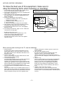
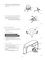
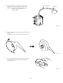
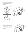
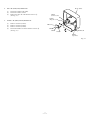
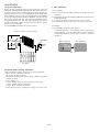
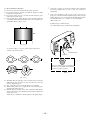
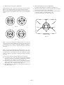
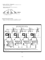
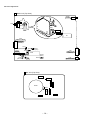
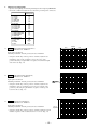
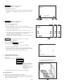
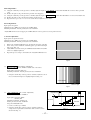
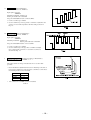
TV-AN1410
NH
SERVICE MANUAL
COLOR TELEVISION
S/M Code No. 09-004-417-4S1
SU
PP
LE
ME
DA
NT
TA
• This Service Manual contains the additional information “NOTICES BEFORE REPAIRING”,
“DISASSEMBLY INSTRUCTIONS” and “ADJUSTMENT” for the model TV-AN1410 (NH).
If requiring the other information, see Service Manual of TV-AN1410 (NH),
(S/M Code No. 09-99B-417-4R1).
NOTICES BEFORE REPAIRING
To make the best use of this equipment, make sure to
obey the following items when repairing (or mending).
1. Do not damage or melt the tunicate of the leading wire on
the AC1 side, including the power supply cord.
2. Do not soil or stain the letters on the spec. inscription plates,
notice labels, fuse labels, etc.
3. When repairing the part extracted from the conducted side
of the board pattern, fix it firmly with applying bond to the
pattern and the part.
4. Restore the following items after repairing.
1) Conditions of soldering of the wires (especially, the
distance on the AC1 side).
2) Conditions of wiring, bundling of wires, etc.
3) Types of the wries.
4) Attachment conditions of all types of the insulation.
5. After repairing, always measure the insulation resistance
and perform the voltage-withstand test (See Fig-1).
1) The insulation resistance must be 1 MΩ when applying
500V per second.
2) In the voltage withstand test, apply 1 kV for 1 minute and
check that the GO lamp lights.
*
*
*
*
Insulation resistance: 1 MΩ (500 V/s)
Voltage-withstand: 1 kV for 1 minute
Safety checker (Model 7110, etc.)
Earth cable
Connect the earth cable
to the outside metal part
terminal.
AC cable
Breaking current set to 10 mA.
Connect the safety checker as shown in Fig-1, then
measure the resistance and perform the test.
Do not touch the equipment during testing.
For details of the safety checker, refer to the supplied
Operation manual.
Fig-1
When servicing and checking on the TV, note the followings.
and high voltage parts. Therefore, put these parts in the
original positions.
5. Take care of the cathode-ray tube.
By setting an explosion-proof cathode-ray tube in this
equipment, safety is secured against implosion.
However, when removing it or servicing from the back, it
gives out shock that is dangerous. Take enough care to deal
with it.
6. Avoid an X-ray.
Safety is secured against an X-ray by giving considerations
to the cathode-ray tube and the high voltage peripheral
circuit, etc. Therefore, when repairing the high voltage
peripheral circuit, use the designated parts and do not
change the circuit. Repairing, except indicates, causes
rising of high voltage, and the cathode-ray tube emits an
X-ray.
7. Perform a safety check after servicing.
Confirm that the screws, parts and wiring which were
removed in order to service are put in the original positions,
or whether there are deteriorated portions around the places
serviced.
1. Keep the notices.
As for the places which need special attentions, they are
indicated with labels or seals on the cabinet, chassis and
parts. Make sure to keep the indications and notices in the
operation manual.
2. Avoid an electric shock.
There is a high voltage part inside. Avoid an electric shock
while the electric current is flowing.
3. Use the designated parts.
The parts in this equipment have the specific characteristics
of incombustibility and withstand voltage for safety.
Therefore, use a part which has the same character as the
replaced part. Especially as to the important parts for safety
which is indicated in the circuit diagram or the table of parts
with a ! mark, the designated parts must be used.
4. Put parts and wires in the original position after assembling
or wiring.
There are parts which use the insulation material such as a
tube or tape for safety, or which are assembled so that these
parts do not make contact with the printed board. The inside
wiring is designed not to get close to the pyrogenic parts
–2–
DISASSEMBLY INSTRUCTIONS
1.
REAR CABINET REMOVAL
(1)
Front cabinet
Remove four screws 1 and three screws 2, then remove
the rear cabinet in the direction of the arrow. (See Fig. 1-1)
1
1
Rear cabinet
1
2
2
2
1
Fig. 1-1
2.
HIGH-VOLTAGE CAP (ANODE CAP) REMOVAL
2-1. Cautions before Removing
Anode cap
Discharge the anode voltage
(1)
The anode voltage is not discharged completely from the
CRT of this unit even after the power is turned off. Be sure
to discharge the residual anode voltage before removing
the anode cap.
CRT GND
Do not use pliers
(2)
Do not use pliers, etc. to remove the anode cap. If you used
pliers and bent the hook to remove the cap, the spring
characteristics of the hook could be lost, and when reinstalled,
the cap would come off from the CRT anode button easily,
causing an accident.
(3)
If the anode cap is turned in the direction of its
circumference, the hook is likely to come off.
Do not turn the anode cap
Grip
Hook
CRT
Fig. 2-1
CRT GND
2-2. Anode Cap Removal
(1)
(2)
(3)
(4)
Anode cap
Discharge the anode voltage. (See Fig. 2-1)
Connect a flat-bladed screwdriver to the CRT GND via an
alligator clip.
Use a tester to check the end of the screwdriver and
ground of the TV for continuity.
Touch the hook with the end of the screwdriver.
Caution : Be careful not to damage the anode cap.
Turn over the anode cap.
Caution : Be careful not to damage the anode cap.
CRT
Anode button
Hook
Fig. 2-2
–3–
(5)
Push the anode cap with your thumb in the direction of
arrow 1 as shown in the figure, then lift the cap in the
direction of arrow 2 to release the hook on one side.
(See Fig. 2-3)
1
2
Anode cap
1
CRT
CRT
Hook
Hook
Fig. 2-3
(6)
Turn over the anode cap on the side where the hook was
released and pull out the cap in the direction opposite to
that on which the cap was pushed. (See Fig. 2-4)
Caution : Do not pull out the anode cap straight up.
: Do not pull the cap forcibly. After removing
the cap, check that the hook is not deformed.
Anode cap
Pull out
CRT
Anode button
Hook
Fig. 2-4
3.
ANODE CAP REINSTALLTION
Anode cap
Observe the cautions carefully so that no accident occurs
due to a defect in installing the anode cap and so it does
not come off.
Left
Right
2-1. Caution before Reinstalling
Never turn the anode cap after installing it
Never re-use the hook when it has been deformed
(1)
(2)
If the anode cap is turned after it is installed, it may come
off. Therefore, arrange the high-voltage cable before
attaching the anode cap. (See Fig. 3-1)
If you have attached the anode cap before arranging the
high-voltage cable, arrange the cable carefully so the cap
does not turn.
Fig. 3-1
3-2. Anode cap reinstallation
(1)
(2)
Anode button
Use a clean cloth moistened slightly with alcohol to clean
the installation section. (See Fig. 3-2)
Caution : Check that the installation section is free
from dust, foreign matter, etc.
Coat the anode cap installation circumference with an
appropriate amount of the specified silicone grease
(KS-650N).
Caution : Be careful that silicone grease does not
enter the anode button.
Installation
section
Fig. 3-2
–4–
(3)
Eliminate twisting, etc. of the high-voltage cable and
arrange it so that no twisting occurs. (See Fig. 3-3)
Caution : If the cable is not arranged correctly, the
anode cap could turn and cause an
installation defect.
High-voltage cable
Anode cap
Fig. 3-3
(4)
Turn over the rubber cap symmetrically on the left and right.
(See Fig. 3-4)
Caution : Take great care not to damage the anode cap.
Fig. 3-4
(5)
Fit your forefinger over the projection at the center of the
cap and hold the cap between your thumb and middle
finger. (See Fig. 3-5)
Fig. 3-5
–5–
(6)
(7)
Apply the hook on one side to the anode button as shown
on the figure. (See Fig. 3-6)
Caution : Check that the hook is held securely.
Apply the hook on the other side to the anode button as
shown in Fig. 3-7.
Anode button
Hook
Hook
30˚
Anode button
Anode button
Hook
Fig. 3-6
Fig. 3-7
(8)
Pull the anode cap slightly with the rubber cap turned over
and visually check that the hook is engaged securely.
(9) Release your hand from the rubber cap of the anode cap.
Caution : Cover the anode cap so that it does not lift.
(10) Hold the skirt of the andoe cap slightly to improve the
close contact between the cap and CRT.
(11) Check that the anode cap is in close contact with the CRT.
(See Fig. 3-8)
Anode cap
Skirt
Fig. 3-8
–6–
4.
NK C.B. (PWB, NK) REMOVAL
(1)
(2)
(2)
5.
Front cabinet
Disconnect CN903 (CRT GND).
Disconnect CN901, CN902.
Remove the NK C.B. in the diection of arrow 1.
(See Fig. 4-1)
CN801
(Power Cord)
CN802
(Degauss cord)
MAIN C.B. (PWB, MAIN) REMOVAL
(1)
(2)
(3)
(4)
Remove connector (CN401).
Remove connector (CN801).
Remove connector (CN802).
Pull out the MAIN C.B. in the direction of arrow 2.
(See Fig. 4-1)
NK C.B
CN902
CN901
MAIN C.B
CN903
CN401
(Speakers)
Fig. 4-1
–7–
ADJUSTMENT
Set-Up For Adjustment
1. CRT Adjustment
Because the video signal output from a pattern generator is used as the
adjustment signal input during adjustment, the video signal output from
the pattern generator must conform with the specifications. Measure the
output waveform across 75Ω load. Confirm that the synchronizing signal
has an amplitude of about 0.3V, the video signal portion has an amplitude
of about 0.7V and the burst signal has an amplitude of about 0.3V with
flat envelope. Confirm that ratio of the burst signal amplitude and the
red signal amplitude is 0.30 : 0.66. If the output signal does not conform
with the specifications, calibrate the pattern generator. (Refer to pattern
generator operation manual.)
Use the LEADER: LCG 404 for the pattern generator.
1-1. Precautions
(1) Receive the white raster signal, and then perform aging for at least
20 minutes.
(2) Demagnetize the area surrounding the CRT with a degausser before
making adjustments.
(3) Set the picture quality for each mode to the factory setting.
(4) Position the front screen facing to the east as much as possible.
1-2. Purpose
(1) Beam landing adjustment (purity magnet)
Set the left/right balance of beam landing. If there is a discrepancy
in this adjustment, a color irregularity will occur. After completion
of the landing adjustment, it is necessary to perform a convergence
adjustment.
Color bar signal of a pattern generator
Approx. 0.7V
1 Vp-p White (Approx.
75%)
Burst signal
Before adjustment
Color
irregularity
Approx.
0.3V
Approx. 0.3V
After adjustment
Black
Red
Blue
Magenta
Cyan
Green
75% white
Yellow
Fig. 1-1
TV display
Precautions Before Starting Adjustment
Satisfy the following setting conditions before starting adjustment.
• Allow warm-up of 20 minutes or longer.
(Do not turn off during warm-up.)
• Set all picture quality controls of users' setting to initial set-up, unless
otherwise specified.
• Picture quality reset
1. Select "Picture" on the screen menu and press enter button.
2. Select "Normal" and press enter button.
3. Select "Reset" and press enter button.
• Set the pattern generator’s output level to 1.0Vp-p (across 75Ω load).
–8–
(2) Beam convergence adjustment (4-pole magnet)
(3) Beam convergence adjustment (6-pole magnet)
With a 4-pole magnet align the G beam with the already aligned
R/B beam.
Align the R beam with the B beam. The G beam does not move
with this adjustment.
(magenta)
(magenta)
B
R/B
R
G
(white)
R/B
G
G
Align the R beam with the B beam
Fig. 1-2
RGB
Align the G beam with the R/B beam
Fig. 1-3
(4) The composition of each magnet is as shown in Fig. 1-4.
In making adjustments, rotate the lock ring clockwise (looking from
the CRT’s back screen) and disengage.
Be careful not to loose the lock ring too much. If the magnet
assembly has become shifted during adjustments, secure it to the
position in Fig. 1-4.
DY lock screw
Purity
4-pole 6-pole Lock ring
Magnet assembly
lock screw
CRT
DY
Magnet assembly
Fig 1-4
–9–
NK C.B
1-3. Beam Landing Adjustment
(1) Receive the green raster signal from the pattern generator.
(2) Loosen the magnet lock screw, and shift the magnet assembly
backward (toward the neck).
(3) Loosen the DY lock screw, and shift the DY deflecting yoke
backward (toward the neck).
(4) After opening the two purity magnets to the same angle, adjust the
color width of the bands on both sides of the screen so that they are
equal width. (Refer to Fig. 1-5 (a)).
*
As there is occurrence of convergence distortion after completing
the landing adjustments, be sure to carry out convergence
adjustments.
*
If the color irregularity in the screen’s corner section are not
improved, correct them with the landing magnet. After using the
landing magnet, be sure to demagnetize the CRT with degausser
and verify that there is no occurrence of color irregularity.
(Refer to Fig. 1-6)
Landing magnet: 81-JTI-710-010
(two-sided adhesive tape) : 80-XVI-218-010 Cushion
R=B
R
G
B
Fig 1-5 (a)
As shown in Fig. 1-5 (b), the purity magnet functions in
relation to the electron beam.
Landing magnet
Cushion
S
N
S
S
N
N
N
S
NS
SN
Since the landing magnet is polarized,
check the screen’s improvement through
rotation, not only by position.
SS
NN
Fig 1-6
Fig 1-5 (b)
(5) Gradually shift the deflecting yoke toward the front (toward the
CRT funnel). Stop movement at the point when the screen has
become completely green.
(6) Also, verify the respective monochromatics of red and blue.
(7) While looking at the screen, adjust the tilt of the deflecting yoke
and tighten the DY lock screw.
(8) Shift the magnet assembly to the front (toward the CRT funnel),
stop movement before the adjustment position and then tighten the
magnet lock screw.
At this time, be careful not to shift the position of the purity magnet.
– 10 –
1-4. Beam Center Convergence Adjustment
1-5. The Surrounding Convergence Adjustment
Make adjustments on the convergence with 4-pole and 6-pole magnets.
Operate each magnet in relation to the electron beam as shown in
Figs. 1-7 and 1-8. When performing this adjustment, verify whether there
is distortion in the focus adjustment. If necessary, carry out adjustments
again.
Perform this adjustment after completion of adjustment 1-4.
(1) Shake the deflecting yoke up, down to the right and left, and adjust
any discrepancies in the screen’s surroundings.
(2) Insert wedges in three locations in the gap between the deflecting
yoke and the surface of the CRT funnel in order
to secure the deflecting yoke. (Refer to Fig. 1-9)
S
S
N
B
G
N
B
N
R
G
R
Wedge
Wedge
N
S
S
Fig 1-7
N
Wedge
S
S
Wedge
N
S
B
G
R
N
B
G
R
S
Position of wedge
N
N
S
S
Fig. 1-9
N
Fig 1-8
In Fig. 1-7, two 4-pole magnets are stacked together so as to be of the
same polarity. Move the B and R beams to their respective direction, by
rotating the two 4-pole magnets together. By adjusting the opening of
the two magnets, it is possible to adjust the amount of the beam’s
movement.
In Fig. 1-8, the two 6-pole magnets are stacked together so as to be of
the same polarity. Move the B and R beams to their respective direction,
by rotating the two 6-pole magnets together. By adjusting the opening
of the two magnets, it is possible to adjust the amount of the beam’s
movement.
(1) Receive the dot pattern signal through the pattern generator.
(2) Pay attention to the center of the screen, and perform adjustments
with two 4-pole magnets so that the R beam and B beam are perfectly
aligned and become a magenta color. (Refer to Fig. 1-2)
(3) In the same way, pay attention to the screen, and perform adjustments
with a 6-pole magnet so that the magenta beam and G beam are
aligned and become a white dot. (Refer to Fig. 1-3)
(4) After adjustments are completed, secure all magnets with the lock
link. (Refer to Fig. 1-4)
– 11 –
Setting Of IIC Bus Data
This model is designed to adjust most parts of the image projection and
deflection by using the jig remote controller.
Preparations:
• Modify the hidden keys on the RC-6VT06 jig remote controller
(TV-C142/86-LB4-951-010) so that they can easily be pressed.
2 keys to be modified (Refer to the below illustration).
Starting service mode:
Hidden key “TEST”:
• Press the “TEST” key on the jig remote controller once to enter to the
“Aging mode” (Refer to Fig. 1).
• Press “TEST” key on the jig remote controller one more time to enter
to the “Adjustment Mode”.
Hidden key “FINISH”:
• The accumulated hours in the aging mode will be reset by pressing
the “FINISH” key on the jig remote controller.
• Do not press this key at the time of general repairs.
AGING
AFT OK 0000H IN-ST
Aging mode operation method:
Make sure that do confirmation after replacing EEP ROM.
Fig. 1
1. Enter to the “Aging Mode” by pressing the “TEST” key on the remote
controller (Refer to Fig. 1).
2. Press the “SYSTEM” key to check the status of distinction switch
(Refer to Fig. 2).
1 MONO
2 IN-ST
3 ST
4 ST+S
5 SPARE
• If the contents are different, choose [IN-ST] by pressing the “1” key
for the destinations.
• For the data, move 0-F by using channel keys and change to “0” or
“1”.
0 1 2 3 4 5 6 7 8 9 A B C D E F
1 1 0 0 1 0 1 1 1 1 1 1 0 1 0 0
Contents of Aging mode:
1. Release “Auto Power Off” function.
Release “Auto Power Off” function when no input is supplied.
Use this mode for warming up (aging) during CRT adjustment.
2. AFT S-curve status indication
The condition of AFT S-curve is indicated by “OK” for suitable
tunning, “UP” for too high or “DN” for too low.
Fig. 2
UP . . . Deviation from standard value high.
AFT S-curve
OK . . . Normal value.
DN . . . Deviation from standard value low.
– 12 –
3. Display of “CRT ON” accumulated hours
The CRT usage time is accumulated on an hourly basis and is
displayed in hexadecimal figures.
Sample calculation of displayed hexadecimal figures :
AFT OK 1234 H IN-ST
* The display will be reset to 0000H when the accumulated hours
exceed 7FFFH(32768 hours).
Adjustment Mode Operation Method:
1. Return to aging display by pressing the “SYSTEM” key and press
“TEST” key once again to enter into the adjustment menu screen.
ADJUSTMENT MENU CHART
PUSH
CH UP/DN KEY
PAGE 1
1 H POS
2 V POS
3 V SIZE
4 OSD POS
5 PIF VCO
6 RF AGC
PUSH
CH UP/DN KEY
PAGE 3
1 SUB CONTRAST
2 SUB BRIGHT
3 SUB TINT
4 SUB COLOR
PAGE 2
00
1 R CUTOFF
00
2 G CUTOFF
00
3 B CUTOFF
00
4 G DRIVE
00
5 B DRIVE
ENTER CONTRAST
00
00
00
00
00
00
PUSH
1~6 KEY
PUSH
1~5 KEY
00
00
00
00
PUSH
1~4 KEY
Press MENU key to return.
PAGE 1
PUSH
CH UP/DN KEY
PAGE 4
1 358 TRAP
2 BPF
3 H AFC
4 WPL
00
00
00
00
PUSH
1~4 KEY
Press MENU key to return.
PAGE 2
PUSH
CH UP/DN KEY
Press MENU key to return.
PAGE 3
Press MENU key to return.
PAGE 4
(Inoperable)
1 H POS
2 V POS
3 V SIZE
1 R CUTOFF
0~31
2 G CUTOFF 0~255
3 B CUTOFF 0~255
0~7
0~63
4 OSD POS
SD
AFT
5 PIF VCO
SD
AFT
6 RF AGC
PUSH
CH UP/DN KEY
-63~+63
1 SUB CONTR...
0~255
4 G DRIVE
0~48
NO
OK
0~127
NO
OK
0~63
5 B DRIVE
2 SUB BRIGHT -63~+63
3 SUB TINT -63~+63
4 SUB COLOR -63~+63
0~255
0~255
1 358 TRAP
1: OFF
3 H AFC
4 WPL
PUSH
CH UP/DN KEY
PUSH
CH UP/DN KEY
0: ON
2 BPF CUTOFF 2: AUTO
0: +2
1: +1
0: OFF
1: ON
PUSH
CH UP/DN KEY
value in the adjustment menu can be modified using the volume adjustment keys (+, -).
* Each
menu contents will be cleared when audio muting key is pressed during menu screen operation and it will be restored by
* The
* pressing “0” key.
Fig.3
– 13 –
Electrical Adjustment
A MAIN C.B (Top View)
SW801
POWER
SFR
T601
(FBT)
T601
(FBT)
FOCUS
SCREEN
IC1
1
J402
VIDEO 1 INPUT
OUTPUT
(REAR)
C213
C332
TP202(FM-DET)
R211 TP201(AFT)
TP203
TU101
J401
VIDEO 2 IN
(FRONT)
AERIAL
IC301
L205
P-IF 1
R103
L201
TP102
S-IF
(RF AGC)
TP302
(PIN 3)
BT301 1
J403
HEADPHONE
B NK C.B (Top View)
R903
R906
SO901
R905
R902
R904
TP903
R901
TP102(IF)
R101
1
1
CN902
CN901
– 14 –
1.
Menu Screen Adjustment
• Operate after inputting the following initial figures when replacing EEP ROM.
• Check the condition and adjust the area where the general repair is carried out.
Initial Figures
PAGE 1
1. H POS
20
2. V POS
2
3. V SIZE
18
4. OSD POS
6
5. PIF VCO
58
6. RF AGC
32
PAGE 2
1. R CUT OFF
127
2. G CUT OFF
127
3. B CUT OFF
127
4. G DRIVE
127
5. B DRIVE
127
PAGE 3
1. SUB CONTRAST
24
2. SUB BRIGHT
35
3. SUB TINT
0
4. SUB COLOR
16
PAGE 4
SPECIFIED FIGURE
1. 3.58 TRAP
ON
2. BPF
AUTO
3. H AFC
+1
4. WPL
OFF
1-1.
8~9
H POS Horizontal Positioning Adjustment /
Adjustment Menu Screen : PAGE 1-1
Center
8~9
PAGE 1
Input signal : Crosshatch
Measuring instrument : Pattern generator / Leader : LCG-404
• Using the volume keys on the jig remote controller, adjust the dot
mark in the centre on the crosshatch screen to the exact centre
position allocating an equal number of squares on both left and right
sides of the dot. (Fig. 1-1)
1 H POS
20
Fig.1-1
1-2.
V POS Vertical Positioning Adjustment /
Adjustment Menu Screen : PAGE 1-2
Input signal : Crosshatch
Measuring instrument : Pattern generator / Leader : LCG-404
• Using the volume keys on the jig remote controller, adjust the dot
mark in the centre of crosshatch screen to the exact vertical centre
position by allocating an equal number of squares on both top and
bottom of the dot. (Fig. 1-2)
1-3.
PAGE 1
V SIZE Vertical Size Adjustment /
Adjustment Menu Screen : PAGE 1-3
Input signal : Crosshatch
Measuring instrument : Pattern generator / Leader : LCG-404
13~14
squares
• Using the volume keys on the jig remote controller, adjust the vertical
number of squares on the crosshatch screen to 13 or 14. (Fig. 1-3)
3 V SIZE
18
Fig.1-3
– 15 –
1-4.
OSD POS OSD Positioning Adjustment /
Adjustment Menu Screen : PAGE 1-4
PAGE 1
Input signal : Not specified
• Using the volume keys on the jig remote controller, adjust + marks on
both side to be an equal distance from the edge of the screen. A=B.
(Fig. 1-4)
OSD POS 6
A
B
Fig.1-4
1-5.
PIF VCO VIDEO IF • VCO Adjustment /
Adjustment Menu Screen : PAGE 1-5
Input signal : ANT RF - INPUT
Color bar
Measuring instrument : Pattern generator / Leader : LCG-404
• Using the volume keys on the jig remote controller, adjust AFT status
on the screen to “OK”. (Fig. 1-5)
• If there is more than one area to adjust, select the average figure.
* “NG” will be indicated for SD when no screen signal was sent. It will
not be any problem for VCO adjustment. (eg. Video input
environment with receiving no signal.)
Even in this case, adjustment is possible if there is a load on ANT.
1-6.
2.
RF AGC RF - AGC / Adjustment Menu Screen : PAGE 1-6
Input signal : ANT RF - INPUT
Color bar
Test point : TP-102 RF - AGC (TU101-PIN1)
Measuring instrument : Oscilloscope
Pattern generator / Leader : LCG-404
PAGE 1
1. Connect oscilloscope to TP102
2. Using the volume keys on the jig remote controller, adjust the test
point voltage becomes to 3.5V±0.3V. And at the same time, confirm
AFT status changes to “OK” as shown in the Fig. 1-6.
SD
OK
AFT
OK
6 RF AGC
32
White Balance Adjustment
Adjustment Menu Screen : PAGE 2-1 ~ 5
Fig.1-6
Input signal
: White raster
Contents of the adjustment : 1. R CUT OFF
2. G CUT OFF
3. B CUT OFF
4. G DRIVE
5. B DRIVE * More than 20 minutes of
aging is required before
adjusting.
* Whole adjustment process
should be repeated for
several times.
Measuring instrument : Pattern generator / Leader : LCG-404
Cut Off Adjustment :
2-1. Input white raster signal by using pattern generator.
2-2. Fix the cut off figure for the brightest color on the screen at 127 and
adjust the other 2 cut off figures for a white picture by using the volume
keys on the jig remote controller.
– 16 –
* User’s picture quality will be cleared when
the adjustment menu screen appears.
Drive Adjustment :
2-3. Using the volume keys on the jig remote controller, adjust the figure of 4. G DRIVE to more than 200 until the screen becomes a greenish
color.
2-4. Reduce the figure to the point where the greenish color disappears.
2-5. Using the volume keys on the jig remote controller, adjust the figure of 5. B DRIVE to more than 200 until the screen becomes bluish color.
2-6. Reduce the figure to the point where the bluish color disappears.
2-7. Repeat the above process of 2-1 to 2-6 for several times to adjust the screen whiter.
Focus Adjustment:
Input signal : Dot pattern
Adjustment point : SFR located at upper part of FBT (T601)
Measuring instrument : Pattern generator / Leader : LCG-404
• Adjust SFR which is located at upper part of FBT (T601) in order to get the best focus point for the dot.
3. Screen Adjustment:
Input signal : No signal (No raster)
Adjustment point : SFR located at lower part of FTB (T601)
Measuring instrument : Pattern generator / Leader : LCG-404
1.
2.
3.
4.
Enter to the “Adjustment Menu Screen” by using the jig remote controller.
Press “0” key of the 10 numeric channel keypad to get a horizontal single
line screen. (Fig. 2-2)
Adjust SFR located at the lower part of FBT (T601) until the horizotal line
starts to be slightly brightened.
Repeat the process of Step 2. and return to the “Adjustment Menu Screen”.
Fig.2-2
3-1.
SUB BRIGHT Sub-brightness Adjustment /
Adjustment Menu Screen : PAGE 3-2 (Make sure of the order)
PAGE 3
Input signal : Color bar (Stair step)
Measuring instrument : Pattern generator / Leader : LCG-404
1. Using the volume keys on the jig remote controller, adjust the scale of
the second last from right to be slightly brightened. (Fig. 3-1)
2 SUB BRIGHT
35
2nd from right
Fig.3-1
3-2.
Pedestal level
SUB CONTRAST Sub-contrast Adjustment /
Adjustment Menu Screen : PAGE 3-1
Input signal : Color bar (QIW)
Chroma / Off
Measuring instrument : Oscilloscope
Pattern generator / Leader : LCG-404
Test point : TP903/NK C.B.
80V±2.0V
75%white
1. Connect oscilloscope to TP903.
2. Using the volume keys on the jig remote controller, adjust the
voltage between pedestal level and 100% white to 80V ± 2.0V as
shown in the Fig. 3-2.
– 17 –
100%white
Fig. 3-2
3-3.
SUB TINT Sub-tint Adjustment /
Adjustment Menu Screen : PAGE 3-3
Input signal : Color bar
VIDEO IN
Measuring instrument : Oscilloscope
Pattern generator/Leader : LCG-404
Test point : TP302/BT301 (wire connector) PIN 3
1. Connect oscilloscope to TP302.
2. Use the volume keys on the jig remote controller to adjust the lower
envelope of waveform tangential to the linear ramp as shown in
Fig. 3-3.
3-4.
SUB COLOR Sub-color Adjustment /
Adjustment Menu Screen : PAGE3-4
Input signal : Color bar
VIDEO IN
Measuring instrument : Oscilloscope
Pattern generator/Leader : LCG-404
Test point : TP302/BT301(wire connector) PIN 3
1. Connect oscilloscope to TP302.
2. Use the volume keys of the jig remote controller and adjust
the top and bottom excursions of waveform to be linear as
shown in the Fig. 3-4.
4.
TV SETTING CHECK Checking of Setting per Model Basis /
Adjustment Menu Screen : PAGE 4-1 ~ 4
The setting details are fixed per model basis. Do not set other than
specified.
• Check whether the adjustment menu screen is matching to the table–4.
If not, use the volume keys on the jig remote controller to search and set
the matching menu screen to the model.
3.58 TRAP
BPF
H AFC
WPL
*
0 : ON
2 : AUTO
1 : +1
0 : OFF
The contents for 3.58 TRAP can not be modified.
Table–4
– 18 –
5.
Tuner Adjustment:
Perform the following adjustment in case of replacing any adjustment element during the repair. Proceed with the following adjustments as well
as in the adjustment menu screen. If those adjustments are not completed on both sides, the required adjustment will not be registered even
thought the adjustment has been processed in the adjustment menu screen.
The components which will be affected due to the repair.
• VCO coil
• SIF coil
5-1.
VCO ADJUSTMENT VCO (PIF) Adjustment /
Video Carrier Frequency Free Running Adjustment
Input signal : RF-Color bar
Input level : 90dBµV
Broadcast CH/fc=45.75MHz
Mode : TUNER
Test point : INPUT/TP-102 IF (TU101-PIN 11)
OUTPUT/TP-201 AFT (IC301-PIN 44)
Adjustment point : L205/P-IF
Measuring instrument : Oscilloscope
Pattern generator / Leader : LCG-404
1. Connect oscilloscope to TP-201.
2. Input specified level of RF signal to TP-102 and adjust L205 until
TP-201 voltage becomes 2.8V±0.3VDC.
5-2.
SIF ADJUSTMENT Audio IF Modulation Adjustment
Input signal : AM/FM-SG RF OUT/4.5MHz - SIF
MOD OFF
90dBµV
• Simple adjustment method receives normal broadcasting.
Mode : TUNER
Test point : INPUT / TP-203 : IC301-PIN 52
OUTPUT / TP-202 : IC301-PIN 54
Adjustment point : L201/S-IF
Measuring instrument : Oscilloscope
AM/FM-Signal generator
1. Connect oscilloscope to TP-202.
2. Input specified signal to TP-203 and adjust L201 until TP-202
voltage becomes 4.5V ± 0.2VDC.
– 19 –
2–11, IKENOHATA 1–CHOME, TAITO-KU, TOKYO 110, JAPAN TEL:03 (3827) 3111
9420025
Printed in Singapore