1
Agilent 34980A
Multifunction
Switch/Measure Unit
Mainframe User’s Guide
Agilent Technologies, Inc.
Printed in Malaysia
Edition 7
March 2013 E0313
*34980-90005*
34980-90005
Agilent Technologies
Notices
© Agilent Technologies, Inc. 2004-2012
Declaration of Conformity
Restricted Rights Legend
No part of this manual may be reproduced
in any form or by any means (including
electronic storage and retrieval or translation into a foreign language) without prior
agreement and written consent from
Agilent Technologies, Inc. as governed
by United States and international copyright laws.
Declarations of Conformity for this
product and for other Agilent products may be downloaded from the
Web. Go to http://regulations.corporate.agilent.com/DoC/search.htm
and click on “Declarations of Conformity.” You can then search by product
number to find the latest Declaration
of Conformity.
U.S. Government Restricted Rights.
Software and technical data rights granted
to the federal government include only
those rights customarily provided to end
user customers. Agilent provides this
customary commercial license in Software and technical data pursuant to FAR
12.211 (Technical Data) and 12.212
(Computer Software) and, for the Department of Defense, DFARS 252.227-7015
(Technical Data - Commercial Items) and
DFARS 227.7202-3 (Rights in Commercial Computer Software or Computer
Software
Documentation).
Manual Part Number
34980-90005
Edition
Seventh Edition, March 2013
Printed in Malaysia
Agilent Technologies, Inc.
3501 Stevens Creek Blvd
Santa Clara, CA 95052 USA
Microsoft® and Windows® are U.S. registered trademarks of Microsoft Corporation.
Software Revision
This guide is valid for the firmware that
was installed in the instrument at the time
of manufacture. However, upgrading the
firmware may add or change product
features. For the latest firmware and
documentation, go to the product page at:
www.agilent.com/find/34980A
Warranty
The material contained in this document is provided “as is,” and is
subject to being changed, without
notice, in future editions. Further,
to the maximum extent permitted
by applicable law, Agilent disclaims
all warranties, either express or
implied, with regard to this manual
and any information contained
herein, including but not limited to
the implied warranties of merchantability and fitness for a particular purpose. Agilent shall not
be liable for errors or for incidental
or consequential damages in connection with the furnishing, use, or
performance of this document or of
any information contained herein.
Should Agilent and the user have a
separate written agreement with
warranty terms covering the material in this document that conflict
with these terms, the warranty
terms in the separate agreement
shall control.
Technology Licenses
The hardware and/or software described
in this document are furnished under a
license and may be used or copied only in
accordance with the terms of such license.
ii
Safety Notices
CAUTION
A CAUTION notice denotes a
hazard. It calls attention to an
operating procedure, practice, or
the like that, if not correctly performed or adhered to, could result
in damage to the product or loss of
important data. Do not proceed
beyond a CAUTION notice until
the indicated conditions are fully
understood and met.
WA RNING
A WARNING notice denotes a
hazard. It calls attention to an
operating procedure, practice,
or the like that, if not correctly
performed or adhered to, could
result in personal injury or
death. Do not proceed beyond a
WARNING notice until the indicated conditions are fully
understood and met.
Agilent 34980A Mainframe User’s Guide
Additional Safety Notices
The following general safety precautions
must be observed during all phases of
operation of this instrument. Failure to
comply with these precautions or with
specific warnings or instructions elsewhere in this manual violates safety standards of design, manufacture, and
intended use of the instrument. Agilent
Technologies assumes no liability of the
customer’s failure to comply with the
requirements.
Do Not Modify the
Instrument
General
Instruments that appear damaged or
defective should be made inoperative and
secured against unintended operation
until they can be repaired by qualified service personnel.
Do not use this products in any manner
not specified by the manufacturer. The
protective features of this product may be
impaired if it is used in a manner not
specified in the operation instructions.
Do not install substitute parts or perform
any unauthorized modification to the
product. Return the product to an Agilent
Sales and Service Office for service and
repair to ensure that safety features are
maintained.
In Case of Damage
Safety Symbols
Before Applying Power
Verify that all safety precautions are
taken. Make all connections to the unit
before applying power.
Ground the Instrument
This product is provided with protective
earth terminals. To minimize shock hazard, the instrument must be connected to
the ac power mains through a grounded
power cable, with the ground wire firmly
connected to an electrical ground (safety
ground) at the power outlet. Any interruption of the protective (grounding) conductor or disconnection of the protective
earth terminal will cause a potential shock
hazard that could result in personal injury.
Do Not Operate in an
Explosive Atmosphere
Do not operate the instrument in the presence of flammable gases or fumes.
Do Not Remove the
Instrument Cover
Only qualified, service-trained personal
who are aware of the hazards involved
should remove instrument covers. Always
disconnect the power cable and any external circuits before removing the instrument cover.
ii
Waste Electrical and
Electronic Equipment
(WEEE) Directive
2002/96/EC
Alternating current
Frame or chassis
terminal
Standby supply. Unit is
not completely
disconnected from ac
mains when switch is off
This product complies with the WEEE
Directive (2002/96/EC) marking requirement. The affixed product label (see
above) indicates that you must not discard this electrical/electronic product
in domestic household waste.
Product Category: With reference to the
equipment types in the WEEE directive
Annex 1, this product is classified as a
“Monitoring and Control instrumentation” product.
To return unwanted products, contact
your local Agilent office, or go to
www.agilent.com/environment/product
for more information.
Caution, risk of
electric shock
Technical Support
Caution, refer to
accompanying
If you have questions about your shipment, or if you need information about
warranty, service, or technical support,
contact
Agilent Technologies:
In the United States: (800) 829-4444
In Europe: 31 20 547 2111
In Japan: 0120-421-345
Or go to www.agilent.com/find/assist
for information on contacting Agilent in
your country of specific location. You can
also contact your Agilent Technologies
Representative.
Contents
1 Introduction to the 34980A
Data Acquisition Overview. . . . . . . . . . . . . . . . . . . . . . . . . . . . . . . . . . . . . . . . . . . . . 2
Measurement Software . . . . . . . . . . . . . . . . . . . . . . . . . . . . . . . . . . . . . . . . . . . . . 3
Data Acquisition Circuitry . . . . . . . . . . . . . . . . . . . . . . . . . . . . . . . . . . . . . . . . . . . 5
Plug-In Modules. . . . . . . . . . . . . . . . . . . . . . . . . . . . . . . . . . . . . . . . . . . . . . . . . . . 6
System Cabling . . . . . . . . . . . . . . . . . . . . . . . . . . . . . . . . . . . . . . . . . . . . . . . . . . . 6
Transducers and Sensors . . . . . . . . . . . . . . . . . . . . . . . . . . . . . . . . . . . . . . . . . . . . 7
Alarm Limits . . . . . . . . . . . . . . . . . . . . . . . . . . . . . . . . . . . . . . . . . . . . . . . . . . . . . 7
Signal Routing and Switching. . . . . . . . . . . . . . . . . . . . . . . . . . . . . . . . . . . . . . . . . . . 8
Switching Topologies. . . . . . . . . . . . . . . . . . . . . . . . . . . . . . . . . . . . . . . . . . . . . . . 8
RF and Microwave Switching . . . . . . . . . . . . . . . . . . . . . . . . . . . . . . . . . . . . . . . 10
Measurement Input . . . . . . . . . . . . . . . . . . . . . . . . . . . . . . . . . . . . . . . . . . . . . . . . . . 11
The Internal DMM . . . . . . . . . . . . . . . . . . . . . . . . . . . . . . . . . . . . . . . . . . . . . . . . 11
Scanning. . . . . . . . . . . . . . . . . . . . . . . . . . . . . . . . . . . . . . . . . . . . . . . . . . . . . . . . 13
Scanning With External Instruments . . . . . . . . . . . . . . . . . . . . . . . . . . . . . . . . . . 14
The Digital Modules . . . . . . . . . . . . . . . . . . . . . . . . . . . . . . . . . . . . . . . . . . . . . . 16
Control Output . . . . . . . . . . . . . . . . . . . . . . . . . . . . . . . . . . . . . . . . . . . . . . . . . . . . . 18
The Digital Modules . . . . . . . . . . . . . . . . . . . . . . . . . . . . . . . . . . . . . . . . . . . . . . 18
The Actuator / General-Purpose Switches . . . . . . . . . . . . . . . . . . . . . . . . . . . . . . 20
2 Getting Started
Front Panel at a Glance . . . . . . . . . . . . . . . . . . . . . . . . . . . . . . . . . . . . . . . . . . . . . . . 22
Rear Panel at a Glance . . . . . . . . . . . . . . . . . . . . . . . . . . . . . . . . . . . . . . . . . . . . . . . 23
Rear Panel Connector Pinouts. . . . . . . . . . . . . . . . . . . . . . . . . . . . . . . . . . . . . . . . . . 24
External Trigger/Alarms Connector (Male D-Sub) . . . . . . . . . . . . . . . . . . . . . . . 24
Analog Bus Connector (Female D-Sub) . . . . . . . . . . . . . . . . . . . . . . . . . . . . . . . 24
Annunciator Display Indicators . . . . . . . . . . . . . . . . . . . . . . . . . . . . . . . . . . . . . . . . 25
Installing and Connecting Modules . . . . . . . . . . . . . . . . . . . . . . . . . . . . . . . . . . . . . 26
Removing a Slot Cover . . . . . . . . . . . . . . . . . . . . . . . . . . . . . . . . . . . . . . . . . . . . 26
Installing a Module . . . . . . . . . . . . . . . . . . . . . . . . . . . . . . . . . . . . . . . . . . . . . . . 27
Instrument Rack Mounting . . . . . . . . . . . . . . . . . . . . . . . . . . . . . . . . . . . . . . . . . . . . 32
Operating the 34980A from the Front Panel Keyboard . . . . . . . . . . . . . . . . . . . . . . 34
Front Panel Menu Reference . . . . . . . . . . . . . . . . . . . . . . . . . . . . . . . . . . . . . . . . 35
Menu Example 1: Setting the Time and Date . . . . . . . . . . . . . . . . . . . . . . . . . . . 37
Menu Example 2: Opening and Closing Channel Relays . . . . . . . . . . . . . . . . . . 38
Using the Measure Keys . . . . . . . . . . . . . . . . . . . . . . . . . . . . . . . . . . . . . . . . . . . 39
Menu Example 3: Configuring the DMM for a Measurement . . . . . . . . . . . . . . 40
Agilent 34980A Mainframe User’s Guide
v
Menu Example 4: Configuring a Channel for a Measurement . . . . . . . . . . . . . . 42
Connecting the 34980A to Your Computer. . . . . . . . . . . . . . . . . . . . . . . . . . . . . . . . 45
Connecting Over LAN . . . . . . . . . . . . . . . . . . . . . . . . . . . . . . . . . . . . . . . . . . . . . 46
Connecting Over GPIB . . . . . . . . . . . . . . . . . . . . . . . . . . . . . . . . . . . . . . . . . . . . 51
Connecting Over USB . . . . . . . . . . . . . . . . . . . . . . . . . . . . . . . . . . . . . . . . . . . . . 52
Communicating with the 34980A . . . . . . . . . . . . . . . . . . . . . . . . . . . . . . . . . . . . . . . 53
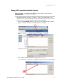
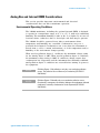
Operating the 34980A using the Integrated Web Browser Interface . . . . . . . . . . . . 53
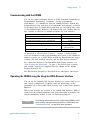
Launching the Web Interface . . . . . . . . . . . . . . . . . . . . . . . . . . . . . . . . . . . . . . . . 54
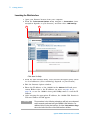
Displaying the Browser Web Control Page . . . . . . . . . . . . . . . . . . . . . . . . . . . . . 55
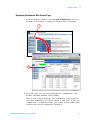
Selecting the “Allow Full Control” Mode . . . . . . . . . . . . . . . . . . . . . . . . . . . . . . 56
Setting a Web Browser Password . . . . . . . . . . . . . . . . . . . . . . . . . . . . . . . . . . . . 56
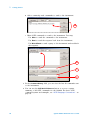
Closing and Opening Channel Relays . . . . . . . . . . . . . . . . . . . . . . . . . . . . . . . . . 57
Modifying the Channel Configuration. . . . . . . . . . . . . . . . . . . . . . . . . . . . . . . . . 58
Sending SCPI Commands Via the Web Interface . . . . . . . . . . . . . . . . . . . . . . . . 59
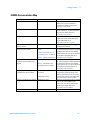
34980A Documentation Map . . . . . . . . . . . . . . . . . . . . . . . . . . . . . . . . . . . . . . . . . . 61
3 Features and Functions
Front Panel Features . . . . . . . . . . . . . . . . . . . . . . . . . . . . . . . . . . . . . . . . . . . . . . . . . 64
Front Panel Display . . . . . . . . . . . . . . . . . . . . . . . . . . . . . . . . . . . . . . . . . . . . . . . 64
Front Panel Controls . . . . . . . . . . . . . . . . . . . . . . . . . . . . . . . . . . . . . . . . . . . . . . 65
Basic Operating Modes . . . . . . . . . . . . . . . . . . . . . . . . . . . . . . . . . . . . . . . . . . . . . . . 66
SCPI Commands . . . . . . . . . . . . . . . . . . . . . . . . . . . . . . . . . . . . . . . . . . . . . . . . . . . . 66
SCPI Language Conventions . . . . . . . . . . . . . . . . . . . . . . . . . . . . . . . . . . . . . . . . 66
Rules for Using a Channel List . . . . . . . . . . . . . . . . . . . . . . . . . . . . . . . . . . . . . . 67
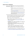
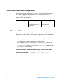
Remote Interface Configuration . . . . . . . . . . . . . . . . . . . . . . . . . . . . . . . . . . . . . . . . 68
GPIB Interface . . . . . . . . . . . . . . . . . . . . . . . . . . . . . . . . . . . . . . . . . . . . . . . . . . . 69
LAN Interface . . . . . . . . . . . . . . . . . . . . . . . . . . . . . . . . . . . . . . . . . . . . . . . . . . . 69
Clearing 34980A Memory . . . . . . . . . . . . . . . . . . . . . . . . . . . . . . . . . . . . . . . . . . . . 78
Volatile Memory . . . . . . . . . . . . . . . . . . . . . . . . . . . . . . . . . . . . . . . . . . . . . . . . . 78
Non-Volatile Memory . . . . . . . . . . . . . . . . . . . . . . . . . . . . . . . . . . . . . . . . . . . . . 78
Analog Bus and Internal DMM Considerations . . . . . . . . . . . . . . . . . . . . . . . . . . . . 79
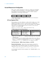
Environmental Operating Conditions . . . . . . . . . . . . . . . . . . . . . . . . . . . . . . . . . 79
Electrical Operating Conditions. . . . . . . . . . . . . . . . . . . . . . . . . . . . . . . . . . . . . . 80
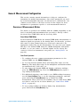
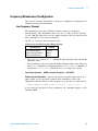
General Measurement Configuration . . . . . . . . . . . . . . . . . . . . . . . . . . . . . . . . . . . . 81
Overview of Measurement Modes. . . . . . . . . . . . . . . . . . . . . . . . . . . . . . . . . . . . 81
Analog Buses . . . . . . . . . . . . . . . . . . . . . . . . . . . . . . . . . . . . . . . . . . . . . . . . . . . . 84
Measurement Functions . . . . . . . . . . . . . . . . . . . . . . . . . . . . . . . . . . . . . . . . . . . . 85
Measurement Range. . . . . . . . . . . . . . . . . . . . . . . . . . . . . . . . . . . . . . . . . . . . . . . 86
Measurement Resolution . . . . . . . . . . . . . . . . . . . . . . . . . . . . . . . . . . . . . . . . . . . 87
Custom A/D Integration Time . . . . . . . . . . . . . . . . . . . . . . . . . . . . . . . . . . . . . . . 88
Autozero. . . . . . . . . . . . . . . . . . . . . . . . . . . . . . . . . . . . . . . . . . . . . . . . . . . . . . . . 89
Trigger Delay . . . . . . . . . . . . . . . . . . . . . . . . . . . . . . . . . . . . . . . . . . . . . . . . . . . . 90
Automatic Trigger Delays . . . . . . . . . . . . . . . . . . . . . . . . . . . . . . . . . . . . . . . . . . 91
Safety Interlock . . . . . . . . . . . . . . . . . . . . . . . . . . . . . . . . . . . . . . . . . . . . . . . . . . 92
User-Defined Channel Labels . . . . . . . . . . . . . . . . . . . . . . . . . . . . . . . . . . . . . . . 93
vi
Agilent 34980A Mainframe User’s Guide
2-Wire Versus 1-Wire Mode . . . . . . . . . . . . . . . . . . . . . . . . . . . . . . . . . . . . . . . . 95
Temperature Measurement Configuration . . . . . . . . . . . . . . . . . . . . . . . . . . . . . . . . 96
Measurement Units . . . . . . . . . . . . . . . . . . . . . . . . . . . . . . . . . . . . . . . . . . . . . . . 96
Thermocouple Measurements . . . . . . . . . . . . . . . . . . . . . . . . . . . . . . . . . . . . . . . 97
RTD Measurements. . . . . . . . . . . . . . . . . . . . . . . . . . . . . . . . . . . . . . . . . . . . . . . 98
Thermistor Measurements. . . . . . . . . . . . . . . . . . . . . . . . . . . . . . . . . . . . . . . . . 100
Voltage Measurement Configuration . . . . . . . . . . . . . . . . . . . . . . . . . . . . . . . . . . . 101
DC Input Resistance . . . . . . . . . . . . . . . . . . . . . . . . . . . . . . . . . . . . . . . . . . . . . 101
AC Low Frequency Filter . . . . . . . . . . . . . . . . . . . . . . . . . . . . . . . . . . . . . . . . . 102
Resistance Measurement Configuration. . . . . . . . . . . . . . . . . . . . . . . . . . . . . . . . . 103
Offset Compensation. . . . . . . . . . . . . . . . . . . . . . . . . . . . . . . . . . . . . . . . . . . . . 103
Current Measurement Configuration . . . . . . . . . . . . . . . . . . . . . . . . . . . . . . . . . . . 104
AC Low Frequency Filter . . . . . . . . . . . . . . . . . . . . . . . . . . . . . . . . . . . . . . . . . 104
Frequency Measurement Configuration . . . . . . . . . . . . . . . . . . . . . . . . . . . . . . . . . 105
Low Frequency Timeout . . . . . . . . . . . . . . . . . . . . . . . . . . . . . . . . . . . . . . . . . . 105
Mx+B Scaling. . . . . . . . . . . . . . . . . . . . . . . . . . . . . . . . . . . . . . . . . . . . . . . . . . . . . 106
Scanning . . . . . . . . . . . . . . . . . . . . . . . . . . . . . . . . . . . . . . . . . . . . . . . . . . . . . . . . .
Rules for Scanning . . . . . . . . . . . . . . . . . . . . . . . . . . . . . . . . . . . . . . . . . . . . . .
Adding Channels to the Scan List . . . . . . . . . . . . . . . . . . . . . . . . . . . . . . . . . . .
Scan Trigger Source . . . . . . . . . . . . . . . . . . . . . . . . . . . . . . . . . . . . . . . . . . . . .
Trigger Count . . . . . . . . . . . . . . . . . . . . . . . . . . . . . . . . . . . . . . . . . . . . . . . . . .
Sweep Count . . . . . . . . . . . . . . . . . . . . . . . . . . . . . . . . . . . . . . . . . . . . . . . . . . .
Sample Count . . . . . . . . . . . . . . . . . . . . . . . . . . . . . . . . . . . . . . . . . . . . . . . . . .
Channel Delay . . . . . . . . . . . . . . . . . . . . . . . . . . . . . . . . . . . . . . . . . . . . . . . . . .
Automatic Channel Delays . . . . . . . . . . . . . . . . . . . . . . . . . . . . . . . . . . . . . . . .
Reading Format . . . . . . . . . . . . . . . . . . . . . . . . . . . . . . . . . . . . . . . . . . . . . . . . .
Non-Sequential Scanning . . . . . . . . . . . . . . . . . . . . . . . . . . . . . . . . . . . . . . . . .
Viewing Readings Stored in Memory . . . . . . . . . . . . . . . . . . . . . . . . . . . . . . . .
108
108
110
112
117
117
118
120
121
123
124
125
Monitor Mode. . . . . . . . . . . . . . . . . . . . . . . . . . . . . . . . . . . . . . . . . . . . . . . . . . . . . 127
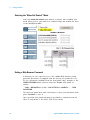
Scanning With External Instruments . . . . . . . . . . . . . . . . . . . . . . . . . . . . . . . . . . . 129
Alarm Limits . . . . . . . . . . . . . . . . . . . . . . . . . . . . . . . . . . . . . . . . . . . . . . . . . . . . .
Viewing Stored Alarm Data . . . . . . . . . . . . . . . . . . . . . . . . . . . . . . . . . . . . . . .
Using the Alarm Output Lines . . . . . . . . . . . . . . . . . . . . . . . . . . . . . . . . . . . . .
Using Alarms With the Digital Modules. . . . . . . . . . . . . . . . . . . . . . . . . . . . . .
132
135
136
138
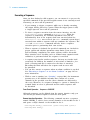
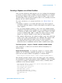
Sequences . . . . . . . . . . . . . . . . . . . . . . . . . . . . . . . . . . . . . . . . . . . . . . . . . . . . . . . .
Defining a Sequence . . . . . . . . . . . . . . . . . . . . . . . . . . . . . . . . . . . . . . . . . . . . .
Querying the Sequence Definition . . . . . . . . . . . . . . . . . . . . . . . . . . . . . . . . . .
Executing a Sequence . . . . . . . . . . . . . . . . . . . . . . . . . . . . . . . . . . . . . . . . . . . .
Executing a Sequence on an Alarm Condition . . . . . . . . . . . . . . . . . . . . . . . . .
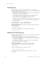
Deleting Sequences . . . . . . . . . . . . . . . . . . . . . . . . . . . . . . . . . . . . . . . . . . . . . .
Reading the List of Stored Sequences. . . . . . . . . . . . . . . . . . . . . . . . . . . . . . . .
140
140
143
144
145
146
146
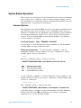
System-Related Operations . . . . . . . . . . . . . . . . . . . . . . . . . . . . . . . . . . . . . . . . . .
Firmware Revision . . . . . . . . . . . . . . . . . . . . . . . . . . . . . . . . . . . . . . . . . . . . . .
Product Firmware Updates . . . . . . . . . . . . . . . . . . . . . . . . . . . . . . . . . . . . . . . .
Instrument State Storage . . . . . . . . . . . . . . . . . . . . . . . . . . . . . . . . . . . . . . . . . .
147
147
148
148
Agilent 34980A Mainframe User’s Guide
vii
Error Conditions. . . . . . . . . . . . . . . . . . . . . . . . . . . . . . . . . . . . . . . . . . . . . . . . . 150
Self-Test . . . . . . . . . . . . . . . . . . . . . . . . . . . . . . . . . . . . . . . . . . . . . . . . . . . . . . . 151
Front-Panel Display Control . . . . . . . . . . . . . . . . . . . . . . . . . . . . . . . . . . . . . . . 151
Front-Panel Number Format . . . . . . . . . . . . . . . . . . . . . . . . . . . . . . . . . . . . . . . 152
Real-Time System Clock . . . . . . . . . . . . . . . . . . . . . . . . . . . . . . . . . . . . . . . . . . 153
Internal DMM Disable . . . . . . . . . . . . . . . . . . . . . . . . . . . . . . . . . . . . . . . . . . . . 153
Relay Cycle Count . . . . . . . . . . . . . . . . . . . . . . . . . . . . . . . . . . . . . . . . . . . . . . . 154
SCPI Language Version . . . . . . . . . . . . . . . . . . . . . . . . . . . . . . . . . . . . . . . . . . . 154
Calibration Overview . . . . . . . . . . . . . . . . . . . . . . . . . . . . . . . . . . . . . . . . . . . . . . . 155
Calibration Security . . . . . . . . . . . . . . . . . . . . . . . . . . . . . . . . . . . . . . . . . . . . . . 155
Calibration Count. . . . . . . . . . . . . . . . . . . . . . . . . . . . . . . . . . . . . . . . . . . . . . . . 156
Calibration Message. . . . . . . . . . . . . . . . . . . . . . . . . . . . . . . . . . . . . . . . . . . . . . 157
Factory Reset State . . . . . . . . . . . . . . . . . . . . . . . . . . . . . . . . . . . . . . . . . . . . . . . . . 158
Instrument Preset State . . . . . . . . . . . . . . . . . . . . . . . . . . . . . . . . . . . . . . . . . . . . . . 160
4 Introduction to the Plug-In Modules for the 34980A
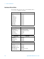
User’s Guides for the 34980A’s Plug-In Modules . . . . . . . . . . . . . . . . . . . . . . . . . 164
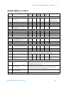
Available Modules, at a Glance. . . . . . . . . . . . . . . . . . . . . . . . . . . . . . . . . . . . . . . . 165
Slot and Channel Addressing Scheme . . . . . . . . . . . . . . . . . . . . . . . . . . . . . . . . . . 166
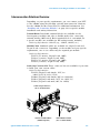
Interconnection Solutions Overview. . . . . . . . . . . . . . . . . . . . . . . . . . . . . . . . . . . . 167
Module Considerations . . . . . . . . . . . . . . . . . . . . . . . . . . . . . . . . . . . . . . . . . . . . . . 168
General Considerations . . . . . . . . . . . . . . . . . . . . . . . . . . . . . . . . . . . . . . . . . . . 168
Environmental Operating Conditions . . . . . . . . . . . . . . . . . . . . . . . . . . . . . . . . 168
Electrical Operating Conditions. . . . . . . . . . . . . . . . . . . . . . . . . . . . . . . . . . . . . 170
viii
Agilent 34980A Mainframe User’s Guide
Agilent 34980A Multifunction Switch/Measure Unit
Mainframe User’s Guide
1
Introduction to the 34980A
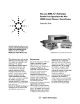
This chapter provides an overview of a computer- based
data acquisition and measurement control system using the
Agilent 34980A Multifunction Switch/Measure Unit and
typical plug- in modules.
Data Acquisition Overview 2
Measurement Software 3
Data Acquisition Circuitry 5
Plug-In Modules 6
System Cabling 6
Transducers and Sensors 7
Alarm Limits 7
Signal Routing and Switching 8
Switching Topologies 8
Multiplexer Switching 8
Matrix Switching 9
General Purpose Switching 9
RF and Microwave Switching 10
Measurement Input 11
The Internal DMM 11
Signal Conditioning, Ranging, and Amplification
Analog-to-Digital Conversion (ADC) 12
Main System Processor 12
Scanning 13
Scanning With External Instruments 14
The Digital Modules 16
Digital Input 16
Totalizer 17
Control Output 18
The Digital Modules 18
Digital Output 18
Voltage (DAC) Output 19
The Actuator / General-Purpose Switches 20
Agilent Technologies
11
1
1
Introduction to the 34980A
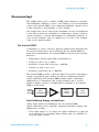
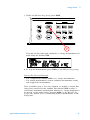
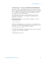
Data Acquisition Overview
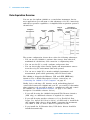
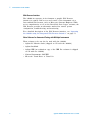
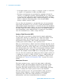
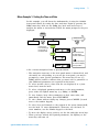
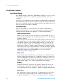
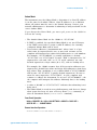
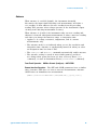
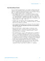
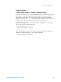
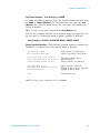
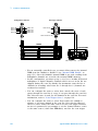
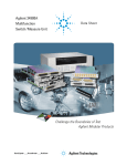
You can use the Agilent 34980A as a stand- alone instrument, but for
most applications you will want to take advantage of its PC connectivity
and remote operation capabilities. A simplified data acquisition system is
shown below.
Computer
and Software
Interface
Cable
34980A
Mainframe
Plug-in
Modules
(up to 8)
Transducers,
Sensors and Events
System
Cabling
The system configuration shown above offers the following advantages:
• You can use the 34980A to perform data storage, data reduction,
mathematical calculations, and conversion to engineering units.
• You can use the PC to easily configure and present data.
• You can electrically isolate analog signals and measurement sensors
from the noisy PC environment and earth ground.
• You can use a single PC to monitor multiple instruments and
measurement points while performing other PC- based tasks.
The 34980A is shipped with Ethernet, USB and GPIB (IEEE- 488)
interfaces. For a detailed description of these connections, see
“Connecting the 34980A to Your Computer” on page 45.
Ideally, before selecting a PC interface mode and making physical
connections between the 34980A and your PC, you would first determine
what software tools you will be using to communicate with and control
the 34980A (see “Measurement Software” on page 3 for a brief
description of available software choices).
• If you will be using the 34980A's integrated Web Browser interface
(LAN only), no additional software is required for connection.
• If you will be using another software tool (e.g. BenchLink Data
Logger Pro, Agilent IO Libraries Suite), you will need to install both
that software and a device driver before connecting the instrument
over GPIB or USB. No device driver is required for LAN.
• If you install the IO Libraries Suite, USB device drivers should be
installed automatically.
2
Agilent 34980A Mainframe User’s Guide
1
Introduction to the 34980A
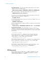
Measurement Software
A variety of software tools are available for remote communication with
the 34980A; the most commonly used tools are briefly discussed below.
Data Logging and Monitoring
Agilent 34832A BenchLink Data Logger Pro is a Windows®- based
application available on CD from Agilent. It is designed to make it easy
to use the 34980A with your PC (over GPIB, USB or LAN) for collecting
and analyzing data. You program the desired measurement, scan and
data logging requirements using an intuitive, tabbed spreadsheet
environment; data is displayed in tabular and graphical formats.
The BenchLink Data Logger Pro software provides several advanced
features not available in the standard BenchLink Data Logger software
(which ships for free on CD- ROM with every 34980A ordered with an
internal DMM). Particularly, the Pro version allows for customized action
scripts, conditional control of external instruments, decision making or
program initiation based on limit checks and alarm events, and advanced
math operations. Both the standard and Pro versions are supplied on the
same CD- ROM. The Pro version can be used for 30 days without
obligation; subsequently a software license is required for its continued
use. Go to www.agilent.com/find/34832A for purchasing information.
Agilent 34980A Mainframe User’s Guide
3
1
Introduction to the 34980A
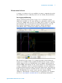
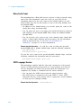
Web Browser Interface
The 34980A incorporates in its firmware a graphic Web Browser
interface for remote LAN access and control of the instrument via a
Java- enabled Web browser, such as Microsoft® Internet Explorer. While
not as comprehensive a tool as the BenchLink Data Logger software, the
Web Browser provides an alternative method for remote system
configuration, troubleshooting, and monitoring.
For a detailed description of the Web Browser interface, see “Operating
the 34980A using the Integrated Web Browser Interface” on page 53.
Other Software for Automated Testing with Multiple Instruments
These software tools can also be used with the 34980A:
• Agilent IO Libraries Suite (shipped on CD with the 34980A)
• Agilent IntuiLink
• Agilent VEE (an evaluation copy of the VEE Pro software is shipped
on CD with the 34980A)
• National Instruments LabVIEW
• Microsoft® Visual Basic or Visual C++
4
Agilent 34980A Mainframe User’s Guide
1
Introduction to the 34980A
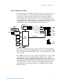
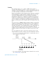
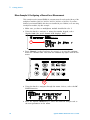
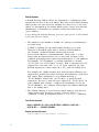
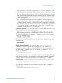
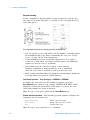
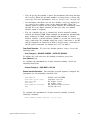
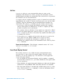
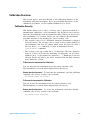
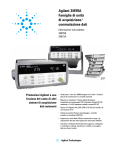
Data Acquisition Circuitry
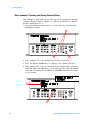
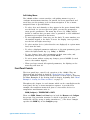
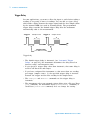
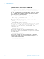
As shown below, the 34980A's main system processor controls all of the
basic functionality of the instrument. This is where the instrument
communicates with the plug- in modules, interacts with command
transactions over the remote interfaces, and controls the optional
internal DMM. The main system processor also performs Mx+B scaling
operations, monitors alarm conditions, converts transducer measurements
to engineering units, adds time stamp information to scanned
measurements, and stores measurement data in memory.
Optional
OUT
IN
Alarms
Internal
External
Trigger
DMM
I
Hi Measure
Lo Measure
Hi Sense
Lo Sense
ABUS1
Analog
Bus
ABUS2
ABUS3
ABUS4
Control
Slot
1000
Slot
2000
Slot
3000
LAN
Main
System
Processor
Digital Bus
USB
GPIB
Slot
8000
AC
Power
The main system processor also controls activity on the four hardware
alarm outputs and external triggering lines. You can use the alarm output
lines to trigger external alarm lights, sirens, or send a TTL pulse to your
control system.
The 34980A provides four 2- wire internal Analog Buses for easier signal
routing. You can route your measurements directly to the optional
internal DMM using the 34980A multiplexer and matrix modules or you
can connect to external signals via the Analog Bus connector located on
the instrument's rear panel. Since four 2- wire buses are provided, you
can dedicate one bus for use with the internal DMM while using the
other three buses for module extensions or additional signal routing
between modules.
Agilent 34980A Mainframe User’s Guide
5
1
Introduction to the 34980A
Plug-In Modules
The 34980A offers a complete selection of plug- in modules to give you
high- quality measurement, switching, and control capabilities. The
plug- in modules communicate with the main system processor via the
internal digital bus. The multiplexer modules also connect to the internal
DMM via the internal Analog Buses. Each module has its own
microprocessor to offload the main system processor and minimize
backplane communications for faster throughput. See Chapter 4,
“Introduction to the Plug- In Modules for the 34980A” for an overview of
the available plug- in modules and their functions. Each module is
shipped with its own User's Guide.
System Cabling
Depending on your specific requirements, you can connect your device
under test (DUT) to the 34980A using several optional interconnection
solutions (see “Interconnection Solutions Overview” on page 167).
Detachable terminal blocks are available for low- frequency modules and
offer an extremely flexible method for connecting external wiring. You
can also connect to the plug- in modules directly using standard cabling
with 50- pin D- Sub and 78- pin D- Sub connectors. Optional solder cup
connector kits are also available if you choose to build your own custom
cabling.
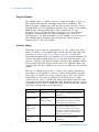
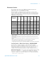
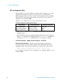
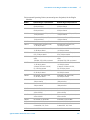
The type of cabling that you use to connect your signals, transducers,
and sensors to the module is critical to ensure measurement integrity.
Some types of transducers, such as thermocouples, have very specific
requirements for the type of cabling that should be used to make
connections. Be sure to consider the usage environment when choosing
wire gauge size and insulation qualities. Wire insulation typically consists
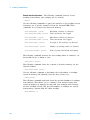
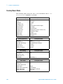
of materials such as PVC or PTFE. The table below lists several common
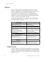
cable types and describes their typical uses.
Cable Type
6
Common Uses
Thermocouple
Extension Wire
Thermocouple
measurements
Twisted Pair,
Shielded Twisted
Pair
Measurement inputs,
voltage outputs,
switching, counting
Shielded
Coaxial,
Double-Shielded
Coaxial
VHF Signal switching
Flat Ribbon,
Twisted Pair
Ribbon
Digital Input/Output
Comments
Available in specific thermocouple types.
Also available in a shielded cable for added
noise immunity.
Most common cable for low-frequency
measurement inputs. Twisted pair reduces
common mode noise. Shielded-twisted pair
provides additional noise immunity.
Most common cable for high-frequency
signal routing. Available in specific
impedance values (50 or 75). Provides
excellent noise immunity. Double-shielded
cable improves isolation between channels.
Requires special connectors.
Often used with mass termination
connectors. These cables provide little
noise immunity.
Agilent 34980A Mainframe User’s Guide
1
Introduction to the 34980A
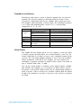
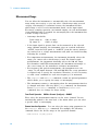
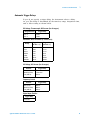
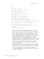
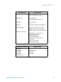
Transducers and Sensors
Transducers and sensors convert a physical quantity into an electrical
quantity. The electrical quantity is measured and the result is then
converted to engineering units by the 34980A's main system processor.
For example, when measuring a thermocouple, the instrument measures
a dc voltage and mathematically converts it to a corresponding
temperature in °C, °F, or K.
Typical Transducer Type
Measurement
Temperature
Pressure
Flow
Strain
Events
Digital
Thermocouple
Resistance temperature detector
(RTD)
Thermistor
Solid state device
Rotary type, thermal type
Resistive elements
Limit switches, optical counters,
rotary encoder
System status
Typical Transducer Output
0 mV to 80 mV
2-wire or 4-wire resistance from 5 to 500
2-wire or 4-wire resistance from 10 to 1M
±10 VDC
4 mA to 20 mA
4-wire resistance from 10 to 10 k
0V or 5V pulse train
TTL levels
Alarm Limits
The 34980A has four alarms which you can configure to alert you when
a reading exceeds specified limits on a channel during a scan. You can
assign a high limit, a low limit, or both to any configured channel in the
scan list. You can assign multiple channels to any of the four available
alarms (numbered 1 through 4). For example, you can configure the
instrument to generate an alarm on Alarm 1 when a limit is exceeded on
any of channels 1003, 2025, or 3020.
You can also assign alarms to channels on the digital modules (34950A
and 34952A). For example, you can generate an alarm when a specific
bit pattern or bit pattern change is detected on a digital input channel or
when a specific count is reached on a totalizer channel. With the digital
modules, the channels do not have to be part of the scan list to generate
an alarm.
Agilent 34980A Mainframe User’s Guide
7
1
Introduction to the 34980A
Signal Routing and Switching
The switching capabilities of the plug- in modules available with the
34980A provide test system flexibility and expandability. You can use the
switching plug- in modules to route signals to and from your test system
or multiplex signals to the internal DMM or external instruments.
Relays are electromechanical devices which are subject to wear- out
failure modes. The life of a relay, or the number of actual operations
before failure, is dependent upon how the relay is used—applied load,
switching frequency, and environment. The 34980A Relay Maintenance
System automatically counts the cycles of each relay in the instrument
and stores the total count in non- volatile memory on each switch
module. You can use this feature to track relay failures and to predict
system maintenance requirements. For more information on using this
feature, refer to “Relay Cycle Count” on page 154.
Switching Topologies
Several switching plug- in modules are available with different topologies
for various applications. The following switching topologies are available:
• Multiplexer (with armature, reed, or FET switches)
• Matrices (with armature or reed switches )
• General Purpose (with Form C or Form A switches)
The following sections describe each of these switching topologies. For
more information, see the individual User's Guides included with each
module.
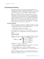
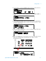
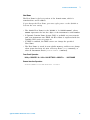
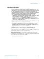
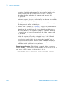
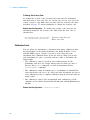
Multiplexer Switching
Multiplexers allow you to connect one of multiple channels to a common
channel, one at a time. A simple 4- to- 1 multiplexer is shown below.
Channel 1
Common
Channel 2
Channel 3
Channel 4
Multiplexers are available in several types:
• One- Wire (Single- Ended) Multiplexers for common LO measurements
• Two- Wire Multiplexers for floating measurements
• Four- Wire Multiplexers for resistance and RTD measurements
• Very High Frequency (VHF) Multiplexers for switching frequencies up
to 3 GHz.
When you combine a multiplexer with a measurement device, like the
optional internal DMM, you create a scanner. For more information on
scanning, see “Scanning” on page 13.
8
Agilent 34980A Mainframe User’s Guide
1
Introduction to the 34980A
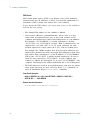
Matrix Switching
A matrix switch connects multiple inputs to multiple outputs and
therefore offers more switching flexibility than a multiplexer. Use a
matrix for switching low- frequency (less than 30 MHz) signals only. A
matrix is arranged in rows and columns. For example, a simple 3x3
matrix could be used to connect three sources to three test points as
shown below.
Source 1
Source 2
Source 3
Test 1
Test 2
Test 3
In a matrix switch configuration, any one of the signal sources can be
connected to any one of the test inputs. Be aware that with a matrix, it
is possible to connect more than one source at the same time. Therefore,
it is important to make sure that dangerous or unwanted conditions are
not created by these connections.
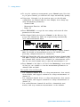
General Purpose Switching
You can use General Purpose (GP) switches to control power connections
to your DUTs, control status indicators, or actuate external power relays
or solenoids. The GP switches for the 34980A are available in two switch
configurations as shown below.
Form C
Form A
Form C switches are also called Single- Pole, Double- Throw (SPDT) and
contain a normally- open (NO) and a normally- closed (NC) contact. Form
A switches are also called Single- Pole, Single- Throw (SPST) and contain
a normally open (NO) contact, which is either open or closed.
Agilent 34980A Mainframe User’s Guide
9
1
Introduction to the 34980A
RF and Microwave Switching
A variety of RF and microwave switch modules are also available for the
34980A. This includes RF multiplexers (34941A, 34942A), SPDT switching
from dc to 20 GHz (34946A, 34947A), and a switch/attenuator driver
module (34945A) that allows you to control switches or attenuators
external to the 34980A mainframe.
For more information, see “Introduction to the Plug- In Modules for the
34980A” on page 163.
CAUTION
10
The 34946A and 34947A support only 24 VDC coil options for the
N1810 switches. If the proper voltage option (Opt. 124) is not used,
the switches could be damaged. N1810 switches also require option
201 “D” subminiature connectors and option 402 Position
Indicators.
Agilent 34980A Mainframe User’s Guide
1
Introduction to the 34980A
Measurement Input
The 34980A allows you to combine a DMM (either internal or external)
with multiplexer channels to create a scan. During a scan, the instrument
connects the internal DMM to the configured multiplexer channels one at
a time and makes a measurement on each channel.
Any channel that can be "read" by the instrument can also be included in
a scan. This includes any combination of temperature, voltage, resistance,
current, frequency, or period measurements on multiplexer channels. A
scan can also include a read of a digital port or a read of the totalizer
count on the digital modules.
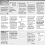
The Internal DMM
A transducer or sensor converts a physical quantity being measured into
an electrical signal which can be measured by the internal DMM. To
make these measurements, the internal DMM incorporates the following
functions:
• Temperature (thermocouple, RTD, and thermistor)
• Voltage (dc and ac up to 300V)
• Resistance (2- wire and 4- wire up to 100 M)
• Current (dc and ac up to 1A)
• Frequency and Period (up to 300 kHz)
The internal DMM provides a universal input front- end for measuring a
variety of transducer types without the need for additional external
signal conditioning. The internal DMM includes signal conditioning,
amplification (or attenuation) and a high resolution (up to 22 bits)
analog- to- digital converter. A simplified block diagram of the internal
DMM is shown below.
Analog
Input
Signal
Signal
Conditioning
Amp
Analog to
Digital
Converter
Main
Processor
Signal Conditioning, Ranging, and Amplification
Analog input signals are multiplexed into the internal DMM's
signal- conditioning section—typically comprising switching, ranging, and
amplification circuitry.
• If the input signal is a dc voltage, the signal conditioner is composed
of an attenuator for the higher input voltages and a dc amplifier for
the lower input voltages.
Agilent 34980A Mainframe User’s Guide
11
1
Introduction to the 34980A
• If the input signal is an ac voltage, a converter is used to convert the
ac signal to its equivalent dc value (true RMS value).
• Resistance measurements are performed by supplying a known dc
current to an unknown resistance and measuring the dc voltage drop
across the resistor. The input signal switching and ranging circuitry,
together with the amplifier circuitry, convert the input to a dc voltage
which is within the measuring range of the internal DMM's
analog- to- digital converter (ADC).
You can allow the instrument to automatically select the measurement
range using autoranging or you can select a fixed measurement range
using manual ranging. Autoranging is convenient because the instrument
automatically decides which range to use for each measurement based on
the input signal. For fastest scanning operation, use manual ranging for
each measurement (some additional time is required for autoranging
since the instrument has to make a range selection).
Analog-to-Digital Conversion (ADC)
The ADC takes a prescaled dc voltage from the signal- conditioning
circuitry and converts it to digital data for output and display on the
34980A front panel. The ADC governs some of the most basic
measurement characteristics. These include measurement resolution,
reading speed, and the ability to reject spurious noise.
There are several analog- to- digital conversion techniques but they can be
divided into two types: integrating and non- integrating. The integrating
techniques measure the average input value over a defined time interval,
thus rejecting many noise sources. The non- integrating techniques sample
the instantaneous value of the input, plus noise, during a very short
interval. The 34980A's internal DMM uses an integrating ADC technique.
You can select the resolution and reading speed from 6 digits (22 bits) at
3 readings per second to 4 digits (16 bits) at up to 3,000 readings per
second. The integration time, resolution, and number of digits are all
interrelated (see “Custom A/D Integration Time” on page 88 for more
details).
Main System Processor
The main system processor controls the input signal conditioning,
ranging, the ADC, and all backplane transactions. The main system
processor synchronizes measurements during scanning and control
operations. The main system processor uses a multi- tasking operating
system to manage the various system resources and demands.
The main system processor also performs Mx+B scaling operations,
monitors alarm conditions, converts transducer measurements to
engineering units, adds time stamp information to scanned
measurements, and stores measurement data in memory.
12
Agilent 34980A Mainframe User’s Guide
1
Introduction to the 34980A
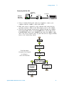
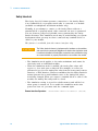
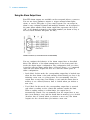
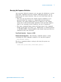
Scanning
The instrument allows you to combine a DMM (either internal or
external) with multiplexer channels to create a scan. During a scan, the
instrument connects the DMM to the configured multiplexer channels one
at a time and makes a measurement on each channel.
Before you can initiate a scan, you must set up a scan list to include all
desired multiplexer or digital channels. Channels which are not in the
scan list are skipped during the scan. By default, the instrument
automatically scans the list of channels in ascending order from slot 1
through slot 8 (channels are reordered as needed). If your application
requires non- ordered scanning of the channels in the present scan list,
you can configure a non- sequential scan. Measurements are taken only
during a scan and only on those channels which are included in the scan
list.
You can store up to 500,000 readings in memory during a scan and all
readings are automatically time stamped. The most recent readings are
always preserved in memory. You can read the contents of memory at
any time, even during a scan. Reading memory is not cleared when you
read it. Each time you start a new scan, the instrument clears all
readings stored in reading memory from the previous scan. Therefore, all
readings currently stored in memory are always from the most recent
scan.
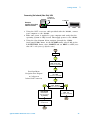
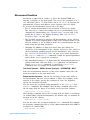
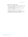
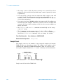
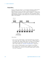
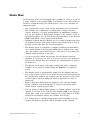
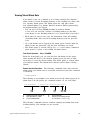
You can configure the event or action that controls the onset of each
sweep through the scan list (a sweep is one pass through the scan list):
• You can set the instrument's internal timer to automatically scan at a
specific interval as shown below.
Scan List
t
Ch 1
Ch 2
Ch 3
Ch 4
Ch 5
Ch 6
t
t1
t2
t3
t4
t5
t6
Channel Delay
(0 to 60 seconds)
• You can also program a time delay between channels in the scan list
(see “Channel Delay” on page 120).
Agilent 34980A Mainframe User’s Guide
13
1
Introduction to the 34980A
• You can manually control a scan by repeatedly pressing the Scan
(Measure) key from the front panel.
• You can start a scan by sending a software command from the remote
interface (MEASure? or INITiate command).
• You can start a scan when an external TTL trigger pulse is received.
• You can start a scan when an alarm event is logged on the channel
being monitored.
For more information on scanning, see “Scanning” on page 108.
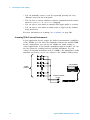
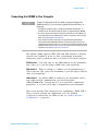
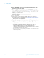
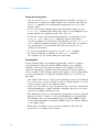
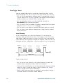
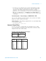
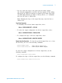
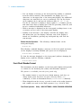
Scanning With External Instruments
If your application doesn't require the built- in measurement capabilities
of the 34980A, you can order the mainframe without the internal DMM.
In this configuration, you can use the 34980A for signal routing or
control applications. If you install a multiplexer plug- in module, you can
use the system for scanning with an external instrument. You can
connect an external instrument such as a DMM to the multiplexer's COM
terminals (see below) or you can connect to the 34980A's analog buses.
External DMM
Input
Channels
Common Terminals
(COM)
L
H
14
Agilent 34980A Mainframe User’s Guide
1
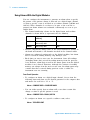
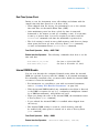
Introduction to the 34980A
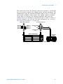
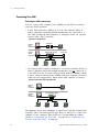
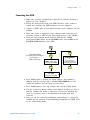
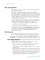
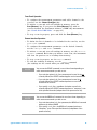
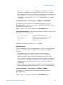
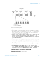
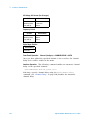
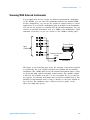
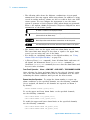
The figure below shows the external connections required to synchronize
the scan sequence between the 34980A and an external instrument. The
34980A must notify the external instrument when a relay is closed and
fully settled (including channel delay). The 34980A outputs a Channel
Closed pulse. In response, the external instrument must notify the
34980A when it has finished its measurement and is ready to advance to
the next channel in the scan list. For more information, see “Scanning
With External Instruments” on page 129.
Analog Bus Connector
ABus1 HI
ABus2 HI
ABus3 HI
ABus4 HI
9
5
6
1
ABus1 LO
ABus2 LO
ABus3 LO
ABus4 LO
Ext Trig Connector
Channel Advance
(In)
GND
6
9
1
5
Channel Closed
(Out)
34980A Mainframe
External
DMM
VM Complete Out
Agilent 34980A Mainframe User’s Guide
Ext Trig In
15
1
Introduction to the 34980A
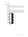
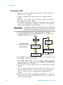
The Digital Modules
The 34950A and 34952A digital modules add two additional measurement
input capabilities to the system: digital input and event totalize. For more
information, see the individual User's Guides included with those
modules.
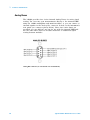
Digital Input
The digital modules have multiple non- isolated 8- bit input/output ports
which you can use for reading digital patterns. You can read the live
status of the bits on the port or you can configure a scan to include a
digital read. Each port has a separate channel number on the module
and contains 8- bits. You can combine ports to read 16- or 32- bit words.
Bit 0
8
Bit 7
Bit 8
8
Bit 15
Bit 16
8
Bit 23
Bit 24
8
Bit 31
16
Agilent 34980A Mainframe User’s Guide
1
Introduction to the 34980A
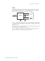
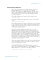
Totalizer
The digital modules have 32- bit totalizer input channels for counting
pulses and measuring frequency. You can manually read the totalizer
count or you can configure a scan to read the count.
Count +
Count -
32 Bits
Totalizer
Gate
Gate
You can configure the totalizer to count on the rising edge or falling edge
of the input signal. The minimum rise/fall time for input signals to the
totalizer is 5 S.
The maximum count is 4,294,967,295 (232 - 1). The count rolls over to "0"
after reaching the maximum allowed value.
You can configure the totalizer to read without affecting the count or
reset the count to zero without losing any counts.
Agilent 34980A Mainframe User’s Guide
17
1
Introduction to the 34980A
Control Output
In addition to signal routing and measurement, you can also use the
34980A to provide simple control outputs. For example, you can control
external high- power relays using the GP switch modules or a digital
output channel.
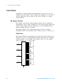
The Digital Modules
The 34950A, 34951A and 34952A digital modules add two additional
measurement control output capabilities to the system: digital output and
voltage (DAC) output. For more information, see the individual User's
Guides included with those modules.
The digital modules also contain digital input and event totalizer
capabilities which are described in more detail on page 16 and page 17.
Digital Output
The digital modules have multiple non- isolated 8- bit input/output ports
which you can use for writing digital patterns. Each port has a separate
channel number on the module and contains 8- bits. You can combine
ports to output 16- or 32- bit words.
Bit 0
8
Bit 7
Bit 8
8
Bit 15
Bit 16
8
Bit 23
Bit 24
8
Bit 31
18
Agilent 34980A Mainframe User’s Guide
1
Introduction to the 34980A
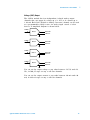
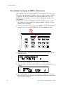
Voltage (DAC) Output
The 34951A module has four independent, isolated analog output
channels that can output dc voltage up to 16V or dc current up to
20 mA. Each DAC (Digital- to- Analog Converter) channel can be used
as a programmable voltage source for analog input control of other
devices. A simplified diagram is shown below.
16 Bits
DAC 1
DAC 1H
DAC 1L
DAC 2
DAC 2H
DAC 2L
DAC 3
DAC 3H
DAC 3L
DAC 4
DAC 4H
DAC 4L
16 Bits
16 Bits
16 Bits
You can set the output voltage to any value between - 16 Vdc and +16
Vdc, in 500 V steps on any or all four channels.
You can set the output current to any value between - 20 mA and +20
mA, in 630 nA steps on any or all four channels.
Agilent 34980A Mainframe User’s Guide
19
1
Introduction to the 34980A
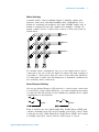
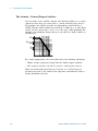
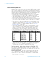
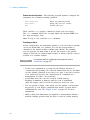
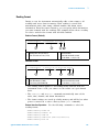
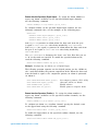
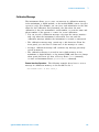
The Actuator / General-Purpose Switches
You can think of the 34937A, 34938A, and 34939A modules as a control
outputs because they are often used to control external power devices.
For example, the 34937A provides 28 independent, isolated Form C
(SPDT) switches. Each channel can switch up to 300V dc or ac rms. Each
switch can also switch up to 1A dc or ac rms up to 60W maximum. For
example, the maximum current that you can switch at 120V is 0.45A as
shown below.
300
120
100
50
30
.2
.5
1
For control applications, the GP modules have the following advantages:
• Higher voltage and power rating than the digital output channels.
• The actuator switches can also be used to control power devices.
When used with high- power devices, however, it is critical that you
provide protection to the switch from capacitive and inductive loads to
ensure maximum relay life.
20
Agilent 34980A Mainframe User’s Guide
Agilent 34980A Multifunction Switch/Measure Unit
Mainframe User’s Guide
2
Getting Started
This chapter provides an overview of the 34980A’s controls,
displays and connections; module assembly, wiring and
installation instructions; and some basics of operation with
examples. It is designed to allow you to gain quick
familiarity with the instrument and start using it.
Front Panel at a Glance 22
Rear Panel at a Glance 23
Rear Panel Connector Pinouts 24
Annunciator Display Indicators 25
Installing and Connecting Modules 26
Installing a Module 27
Wiring and Installing a Terminal Block 29
Instrument Rack Mounting 32
Operating the 34980A from the Front Panel Keyboard 34
Front Panel Menu Reference 35
Menu Example 1: Setting the Time and Date 37
Menu Example 2: Opening and Closing Channel Relays 38
Using the Measure Keys 39
Menu Example 3: Configuring the DMM for a Measurement 40
Menu Example 4: Configuring a Channel for a Measurement 42
Connecting the 34980A to Your Computer 45
Connecting Over LAN 46
Connecting Over GPIB 51
Connecting Over USB 52
Communicating with the 34980A 53
Operating the 34980A using the Integrated Web Browser Interface 53
Launching the Web Interface 54
Displaying the Browser Web Control Page 55
Selecting the “Allow Full Control” Mode 56
Setting a Web Browser Password 56
Closing and Opening Channel Relays 57
Modifying the Channel Configuration 58
Sending SCPI Commands Via the Web Interface 59
34980A Documentation Map 61
Agilent Technologies
21
2
Getting Started
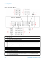
Front Panel at a Glance
1
2
3
4
5
6
7
8
9
10
11
12
13
22
The On/Standby switch is used to toggle the 34980A between On and Standby modes only. To turn the unit off, remove
the power cord.
The Utility key accesses menus to configure Remote I/O (LAN, GPIB, and USB) operation, set Date and Time, and
configure other system-related instrument parameters.
The Store/Recall key allows you to save and recall up to six instrument setups.
Control keys directly control module actions.
The number keypad is used for entering numerical characters.
The exponent entry key is used to enter the exponent during a numerical entry.
The Cancel key exits any menu without saving changes.
Arrow keys move the cursor position in an entry.
The knob provides for entry of alphanumeric characters, selecting slots or channels, and navigating menus.
The Enter key steps you through a menu or saves number entries.
Running a program puts the display into “remote” and disables the front panel keys. Local takes you out of “remote”
mode and enables the front panel keys.
Configure keys select functions and set function parameters.
Measure keys execute and monitor measurements. Depending on which measurement key you use, you can have
complete/direct control over the switching and measurement operation, or you can have the 34980A automatically
control these to capture the desired data.
Agilent 34980A Mainframe User’s Guide
2
Getting Started
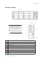
Rear Panel at a Glance
Safety Symbols Located on Rear Panel
Warning. Risk of electric shock
Caution. Refer to accompanying
descriptions in User’s Guide
Alternating Current
Mainframe Chassis Ground
1
2
3
4
5
6
7
8
9
10
11
12
Access to Analog Buses (shown with removable cover installed). For pinouts, see page 24.
Module installed in slot 1
Slot identifier
Module ground screw
Slot cover over slot 2
AC power connector
LAN connector (10Base T/100Base Tx)
USB 2.0 connector
External trigger input. For pinouts, see page 24.
Internal DMM option mark. If you ordered the internal DMM option, the circle is marked black.
IEEE 488.2 GPIB Connector
Chassis ground screw
Agilent 34980A Mainframe User’s Guide
23
2
Getting Started
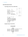
Rear Panel Connector Pinouts
External Trigger/Alarms Connector (Male D-Sub)
Analog Bus Connector (Female D-Sub)
24
Agilent 34980A Mainframe User’s Guide
2
Getting Started
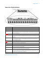
Annunciator Display Indicators
Display Indicator
LAN
USB
GPIB
ABUS [1234]
ERROR
Rmt
Safety Interlock
Trig
HOT
ALARM (H1234L)
Mx+B
4W
OC
*
Definition
Lit when communicating with the 34980A over LAN.
Lit when communicating with the 34980A over USB.
Lit when communicating with the 34980A over GPIB.
Indicates Analog Bus (ABus) connectivity. Normally, this shows the designated ABus connected on any
module in the mainframe. During a scan, if ABus 1 and ABus 2 are both indicated, they will be used at
some point during that scan.
When lit, an error has been generated and is in the error queue.
Indicates Remote mode is in use. Running a program puts the display into “remote” mode and disables
the front panel keys. Pressing the LOCAL button takes you out of “remote” mode and enables the front
panel keys.
Indicates an ABus Safety Interlock. When lit, at least one terminal block or cable has been removed from
the D-sub connector of a module. For more information, see page 92 and the User’s Guides for the
appropriate Multiplexer Modules.
Lit when the 34980A is waiting for an external or manual trigger during scans.
Indicates an over-temperature condition. When lit, one or more general purpose (34937A/34938A)
modules have reached their over-temperature limits.
A HI or LO alarm condition has occurred on the indicated alarms.
Alarms are enabled on the displayed channel.
Scaling is enabled on the displayed channel. This appears on display after you have selected the scaling
function via the front panel or remote interface.
A 4-wire measurement is specified on the displayed channel. This appears on the display after you have
selected the 4-wire function via the front panel or remote interface.
Lit when Offset Compensation has been specified for a given measurement. This appears on the display
after you have selected the offset compensation function via the front panel or remote interface. For more
information, see “Offset Compensation” on page 103
A measurement is in progress.
Agilent 34980A Mainframe User’s Guide
25
2
Getting Started
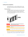
Installing and Connecting Modules
For most applications, prior to using the 34980A you will select and
install modules, and make connections with terminal blocks or cabling.
The following sections illustrate module and terminal block installation.
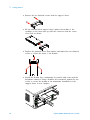
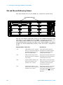
Removing a Slot Cover
Your 34980A is shipped from the factory with one slot uncovered and
the remaining seven slots covered (the illustration below shows a module
already inserted in Slot 1). When you are ready to install additional
modules in the seven remaining slots, you must first remove its slot
cover. Using a flat blade screwdriver, pry each side of the slot cover until
the cover releases from the slot.
WA RNING
CAUTION
CAUTION
When any slot covers are removed, hazardous voltages may be
exposed on the analog bus connectors.
Install current limiting devices between high energy sources and the
module inputs.
Do not block air intake or exhaust vents at the sides of the instrument
With the slot cover removed, you can now install a module in this slot.
For detailed examples of the slot and channel numbering scheme used in
the 34980A, see “Slot and Channel Addressing Scheme” on page 166.
26
Agilent 34980A Mainframe User’s Guide
2
Getting Started
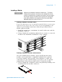
Installing a Module
NOT E
Applies to the multiplexer and matrix modules only — The Safety
Interlock feature prevents connections to the Analog Buses from a
module if a terminal block or properly-wired cable is not connected to
that module. If proper connections are not present, the Analog Bus
relays will be disabled on that module and the front panel Safety
Interlock display annunciator will turn on.
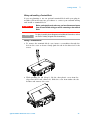
Installing a Module for Use with Cables
If you are planning to use an optional terminal block to connect your
external wiring, skip to the next section. If you are planning to use
cables for your external connections, follow the procedure below to
install a plug- in module:
1 Install the module into a mainframe slot until it fully seats with the
backplane connector.
2 Using a Pozidriv #1 screwdriver, tighten the two screws to secure the
module in the mainframe. Installation is now complete.
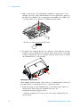
Installing a Module for Use with Terminal Blocks
All of the 34980A plug- in modules, except the RF and microwave
modules, can be used with a compatible terminal blocks (optional
accessories 349xxT), which provide screw terminals or solder cup
connections for your external wiring. If you plan to use an optional
terminal block, follow the procedure below to install the module:
1 Using a Pozidriv #1 screwdriver, remove the panhead grounding screw
located between the module connectors.
Agilent 34980A Mainframe User’s Guide
27
2
Getting Started
2 Remove the two flathead screws from the support sleeve.
3 Fit the terminal block support sleeve against the module so the
openings on the sleeve line up with the connectors and the center
screw hole as shown.
4 Replace the panhead screw. Then replace and tighten the two flathead
screws to secure the sleeve to the module.
5 Install the module into a mainframe slot until it fully seats with the
backplane connector. Using a Pozidriv #1 screwdriver, tighten the two
screws to secure the module in the mainframe. Installation of the
support sleeve is now complete.
28
Agilent 34980A Mainframe User’s Guide
2
Getting Started
Wiring and Installing a Terminal Block
If you are planning to use an optional terminal block with your plug- in
modules, follow the next two procedures to connect your external wiring
and install a terminal block.
WA RNING
Before you begin this task, make sure you have disconnected power
from all external field wiring you will be connecting to the terminal
block.
NOT E
For plug-in module pinout diagrams and additional information, refer to
the User's Guide(s) shipped with the module(s).
Wiring a Terminal Block
1 To remove the terminal block cover, insert a screwdriver through the
hole in the cover as shown. Gently push the tab in the direction of the
arrow.
2 While pushing the tab (Step 1), lift the clear plastic cover from the
edge near the D- sub connectors. Slide the cover from under the tab
holders and remove the cover.
Agilent 34980A Mainframe User’s Guide
29
2
Getting Started
3 Make connections to the individual terminals as appropriate. Use a
suitable wire type, gauge and insulation for your application (typical is
20 AWG; the terminals can accommodate a maximum of 18 AWG). Use
a 2.5 mm cable tie as shown for additional strain relief.
Wire Size: 20 AWG (typical); 18 AWG (max)
6 mm
4 To replace the terminal block cover, slide the cover tabs into the tab
holders on the terminal block as shown. Press down on the cover until
it snaps securely into place. Continue with the next section to install
the terminal block to the module.
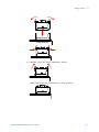
Installing a Terminal Block
After making external wiring connections to a terminal block, follow the
procedure below to fasten the block to a plug- in module.
1 Push the levers on the terminal block to the fully- open position as
shown below. Then slide the terminal block into the
instrument- mounted support sleeve...
…until the terminal block stops at the two points indicated by the
arrows below.
30
Agilent 34980A Mainframe User’s Guide
2
Getting Started
Terminal Block
Support Sleeve
34980A Mainframe
2 Carefully rotate the levers upward as shown…
…until both levers are locked in the closed position.
Agilent 34980A Mainframe User’s Guide
31
2
Getting Started
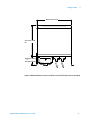
Instrument Rack Mounting
The Agilent 34980A Mainframe can be mounted in a standard 19 inch
instrument rack or in an Agilent rack cabinet. Orientation can be either
forward mounted (front panel facing the front of the cabinet) or reverse
mounted (rear panel facing the front of the cabinet).
Either method will require a set of cabinet rails to support the
instrument’s weight and planned orientation, and a set of mounting
brackets to secure the unit to the cabinet.
Agilent- supplied rail kits are available for Agilent cabinets only; for all
other racks contact the rack’s vendor. The following rack mounting kits
and rail kits are available from Agilent:
Agilent Part
Kit Contents
Y1130A Rack Mount Kit
2 short brackets for forward mounting, 2 longer brackets
for reverse mounting, and associated hardware
Standard Rack Mount Kit,
part number 5063-9214
2 short brackets for forward mounting and associated
hardware
E3663A Basic Rail Kit
2 rails and associated hardware for forward mounting in
an Agilent cabinet
E3664AC Third Party Rail Kit
2 rails and associated hardware for reverse mounting in an
Agilent cabinet
• For forward rack mounting, use the short brackets from the Agilent
Standard rack mount kit or Y1130A Rack Mount Kit. For Agilent rack
cabinets, use the E3663A Basic Rail Kit.
• For reverse rack mounting use the longer brackets (see figure below)
from the Y1130A Rack Mount Kit. For Agilent rack cabinets, use the
E3664AC Third Party Rail Kit.
Agilent 34980A (shown with Reverse Rack Mount brackets installed)
32
Agilent 34980A Mainframe User’s Guide
2
Getting Started
425.6 mm (16.76 in)
367.7 mm (14.48
in)
101.9 mm (4.01 in)
or
70.4 mm (2.78 in)
Agilent 34980A Dimensions (shown with Reverse Rack Mount brackets installed)
Agilent 34980A Mainframe User’s Guide
33
2
Getting Started
Operating the 34980A from the Front Panel Keyboard
This section gives an overview on operating the 34980A from the front
panel keyboard. The Front Panel Menu Reference subsection briefly
describes the menus accessed by the front panel keys, and the
subsequent subsections provide examples of menu navigation.
NOT E
Before you can operate the front panel keyboard, connect the power
cord to the 34980A and turn on the power. If the instrument does not
power on properly, contact Agilent Technologies Technical Support.
At power on, all segments on the front panel are displayed and all
lighted keys temporarily turn on. The front panel is ready for operation
when the keys are no longer lit and the green channel field on the
display shows the first slot in which a module is installed.
34
Agilent 34980A Mainframe User’s Guide
2
Getting Started
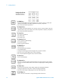
Front Panel Menu Reference
This subsection provides an overview of the top two levels of menus you
can access from the front panel. The menus are designed to sequentially
guide you through all parameters required to configure a particular
function or operation.
The Store/Recall Menu
Use to store and recall instrument states. You can:
• Store up to six instrument states in non-volatile memory;
• Assign a name to each storage location;
• Recall stored states, the power-down state, the factory reset state, or a preset state.
The Utility menu
Use to configure system-related instrument parameters. You can:
• Connect and configure the 34980A to use over LAN, GPIB, or USB;
• Set the real time clock and calendar;
• Set the radix character and thousand separator;
• Enable/disable the internal DMM;
• Query and update the firmware revisions for the mainframe and its modules.
Measurement configuration parameters are set using the Configure key
group (see descriptions on page 36)
Agilent 34980A Mainframe User’s Guide
35
2
Getting Started
Configure Key Group
Use these menus to set
measurement parameters.
The DMM Menu
• Set the internal DMM’s measurement function (AC volts, DC volts, AC current, DC
current, 2-wire ohms, 4-wire ohms, temperature, frequency, and period)
• Set measurement function parameters
The Channel Menu
• Set channel measurement function (AC volts, DC volts, AC current (34921A only), DC
current (34921A only) 2-wire ohms, 4-wire ohms, temperature, frequency, and period)
• Set measurement function parameters
The Scan Menu
• Set trigger-in parameters
• Set sweep count
• Set sample count
The Sequence Menu
• View a sequence command string
• Execute the sequence
• Delete sequence definitions
The Module Menu
• Open all relays
• Clear all measurement functions
• Clear channel labels
• Configure external trigger and clock (applies only to 34951A module)
• Set trace or level mode (applies only to 34951A module)
• Set waveform parameters (applies only to 34951A module)
The View Menu
• View errors and alarms
The Advanced Key
This key is reserved to operate advanced functions in a future firmware release. When
activated, you will be notified in the release notes accompanying the enabling firmware
revision.
The Alarm Menu
• Select one of four alarms to report alarm conditions on the displayed channel
• Configure a high limit, a low limit, or both for the displayed channel
• Select the slope (rising or falling edge) for the four alarm output lines
The Exit Menu Key
Press to leave the current menu, saving all changes made in that menu
36
Agilent 34980A Mainframe User’s Guide
2
Getting Started
Menu Example 1: Setting the Time and Date
In this example, you will learn the fundamentals of using the 34980A
front- panel menus by setting the date and time. Begin by pressing the
Utility menu key, then use the Utility key, knob and arrow keys to
navigate the menu as shown below. Follow the menu prompts as they are
displayed.
Utility
...
REMOTE I/O
Additional Choices
DATE / TIME
Use the knob
to scroll through
the choices on
the same level.
Utility
YEAR
and
Also use the knob
to enter alphanumeric characters.
Utility
MONTH
...
MINUTE
and
Use the arrow keys
to move the display
cursor position.
A list of menu navigation hints is provided below:
• The navigation structure of the front panel menus is hierarchical, and
the menus are self- guiding; as you use the front panel, you may be
prompted to enter specific parameters. The menu key in use (e.g.
Utility) will be backlit to indicate that you must select a parameter or
that additional parameters are required in that menu.
• To select another choice (other than the one displayed) at a given
menu level, turn the knob.
• To select a displayed parameter and move to the next parameter,
press either the lighted menu key (e.g. Utility) or ENTER.
• To save changes, keep other parameters at their same value, and
immediately exit the menu, press EXIT MENU.
• To exit a menu without saving any changes, press CANCEL (located
next to the number keypad).
• To select slots and channels so they appear in the green channel field,
use the knob. To enter alphanumeric characters, use the knob. To
enter numbers, use the number keypad or the knob.
• To move the display cursor position, use the left and right arrow keys.
• When you have entered all required parameters, the lighting on the
menu key will turn off.
Agilent 34980A Mainframe User’s Guide
37
2
Getting Started
Menu Example 2: Opening and Closing Channel Relays
This example is applicable for use with any of the multiplexer modules
(34921A, 34922A, 34923A, 34924A, or 34925A); it illustrates a 34921A
module installed in slot 1.
1 Using the number keypad, press 1 to select the slot containing the
multiplexer module.
2
1
3
2 Select channel 27 on the module by pressing 2 and then 7.
3 Press the lighted ENTER key to complete your channel selection.
4 With channel 1027 selected (shown in green channel field on display),
toggle the Close and Open keys to close and open the selected channel.
Note that the display shows OPEN or CLOSED, indicating the status
of the channel.
4
4
38
Agilent 34980A Mainframe User’s Guide
2
Getting Started
Using the Measure Keys
In Menu Examples 2 and 3 (the following two subsections), you will use
keys in the front- panel Measure group. The three keys in the Measure
group control the initiation of measurements (conversely, the menu keys
in the Configure group allow you to set parameters for measurements).
Depending on which measurement key you select, you can have
complete/direct control over the switching and measurement operations,
or you can allow the 34980A to automatically control the measurement to
capture the desired data.
The three keys in the Measure group are:
• DMM - When pressed, the internal DMM takes
continuous measurements on whatever signal you have
routed to it. This mode allows the most flexibility, but
you must manually control the opening and closing of
relays.
• Channel - When pressed, the 34980A controls the
relays needed for the internal DMM to make
continuous measurements on a single selected
channel. The measurement configuration used for a
particular channel (as specified in the Channel menu
in the Configure group) is stored and recalled
whenever you select that channel.
• Scan - When pressed, the 34980A controls all the relays
required to make a series of sequential measurements,
even across multiple channels with unlike
measurement functions. Scan takes the measurements
and stores the results in volatile memory.
Agilent 34980A Mainframe User’s Guide
39
2
Getting Started
Menu Example 3: Configuring the DMM for a Measurement
This example uses the internal DMM for a measurement. It can be used
with any of the multiplexer modules (34921A, 34922A, 34923A, 34924A,
or 34925A). If you have disabled your internal DMM, don't have one
installed in your 34980A, or are not using a multiplexer module, skip
this example.
1 Make sure you have a multiplexer module installed in slot 1. Select
any channel on this module (the channel number is shown in green
channel field on display).
2 Within the Configure key group, press DMM to set the measurement
parameters for the internal DMM. Note that the DMM key lights.
2
3 Using the knob to navigate through the menu choices, select the AC
VOLTS function.
4 Press the lighted DMM key to accept the ac voltage function.
5 Using the knob, select 10V, which indicates the range parameter for ac
voltage.
6 Press EXIT MENU to save your selections (ac voltage, 10 volt range)
and immediately exit the menu. All unmodified parameters within the
menu remain unchanged.
40
Agilent 34980A Mainframe User’s Guide
2
Getting Started
7 Within the Measure key group, press DMM.
7
Note that the key lights and continuous ac voltage measurements are
made using the internal DMM.
8 To stop the measurements, press DMM (in the Measure key group).
During This Tutorial Example:
• You configured the internal DMM for ac voltage measurements,
• You started measurements, viewed continuous measurement results,
and stopped the measurements.
Since you didn't open or close any channels, no module or Analog Bus
relays were exercised in this example. The internal DMM acted as a
stand- alone instrument and measured whatever ac voltages happened to
be present on the Analog Buses. Pressing DMM (in the Measure key
group) also allowed you to continuously monitor measurements on the
front panel.
Agilent 34980A Mainframe User’s Guide
41
2
Getting Started
Menu Example 4: Configuring a Channel for a Measurement
This example uses the internal DMM for a measurement. It can be used with any of the
multiplexer modules (34921A, 34922A, 34923A, 34924A, or 34925A). If you have
disabled your internal DMM, don't have one installed in your 34980A, or are not using
a multiplexer module, skip this example.
1 Make sure you have a multiplexer module installed in slot 1.
2 Using the knob to navigate or using the number keypad, select
Channel 1016 (the green channel field displays 1016).
2
3 Press Channel (in the Configure key group) to access the configure
menu for Channel 1016. Note that the Channel key lights while in the
menu.
3
4 Using the knob to navigate through the menu choices, select the DC
VOLTS function.
5 Press the lighted Channel key to select this function and proceed to
the next parameter in the menu.
42
Agilent 34980A Mainframe User’s Guide
2
Getting Started
6 Use the knob to select the 100 mV range for the dc voltage function.
7 Continue pressing the lighted Channel key until CHANNEL LABEL is
shown.
8 At the CHANNEL LABEL choice, use the knob (to select alphanumeric
characters) and the arrow keys (to select the cursor position) to enter
a custom channel label.
9 Press the lighted Channel key to save the assigned channel label and
all other changes you made.
10 Press the Channel key (in the Measure key group). Note that the key
lights, the required relays automatically close, and dc voltage
measurements begin.
10
Agilent 34980A Mainframe User’s Guide
43
2
Getting Started
11 To stop the continuous measurements, press Channel again. Note that
as you press Channel, you will hear the relays automatically opening.
12 Using steps 1 through 6 on the previous page, set the following
configuration for Channel 1014 (for this example, don't change any
other measurement parameters):
• Channel: 1014
• Measurement Function: AC Volts
• Range: 1V
13 Press EXIT MENU to accept the new settings and retain all other
parameters in this menu.
14 With Channel 1014 selected, press Channel (in the Measure key
group). The Channel key lights, the required relays automatically
close, and measurements begin.
15 With the Channel key still lighted, turn the knob to display channel
1016. You should see measurements start for DC VOLTS (your
previously configured function for channel 16).
16 With the Channel key still active, turn the knob between channels 1016
and 1014 to monitor the measurement results for each channel. As you
pass Channel 1015, which is not configured for a measurement, notice
that the associated channel relay is open and measurement is off.
17 Press Channel so the light is off. Notice that Monitoring is now turned
off, but you can continue to view the measurement parameters on
channels 1014 and 1016.
During This Tutorial Example:
• You configured channel 16 for dc voltage measurements, then started,
viewed results, and stopped continuous dc voltage measurements on
channel 16.
• You configured channel 14 for ac voltage measurements, then started,
viewed results, and stopped continuous ac voltage measurements on
channel 14.
• You scrolled between channels 14 and 16 to alternatively start,
monitor, and stop continuous measurements on the channels.
44
Agilent 34980A Mainframe User’s Guide
2
Getting Started
Connecting the 34980A to Your Computer
NOT E
To easily configure and verify an interface connection between the
34980A and your PC, you can use the Agilent IO Libraries Suite or an
equivalent.
• The Agilent IO Libraries Suite—along with installation instructions—is
provided on the Automation-Ready CD, which is shipped with your 34980A.
• Previous versions of the Agilent IO Libraries software are also available. For
more information and to download the current or an earlier version from the
Web, go to www.agilent.com/find/iolib.
• The procedures in this section refer to the Connectivity Guide (Agilent
Technologies USB/LAN/GPIB Interfaces Connectivity Guide). If you have
installed the IO Libraries Suite, you can access the Connectivity Guide via the
Agilent IO Libraries Control icon. Or, you can access the Connectivity Guide via
the Web at www.agilent.com/find/connectivity.
The Agilent 34980A supports GPIB, USB, and LAN interfaces. All three
interfaces are enabled at power on. The corresponding front- panel
annunciator turns on whenever there is activity on the remote interface.
GPIB Interface You need only set the GPIB address for the instrument
and connect it to your PC using a GPIB cable (sold separately).
USB Interface There is nothing to configure on your instrument for a
USB connection. Just connect the instrument to your PC using a USB 2.0
cable (sold separately).
LAN Interface By default, DHCP is enabled on the instrument, which
may enable network communication over the LAN interface
(10BaseT/100BaseTx). You may need to set several LAN configuration
parameters. A crossover LAN cable is shipped with your instrument.
This section provides basic instructions for establishing a GPIB, USB or
LAN connection between the 34980A and a PC. For detailed
configuration instructions for GPIB or LAN, see “Remote Interface
Configuration” on page 68.
Agilent 34980A Mainframe User’s Guide
45
2
Getting Started
Connecting Over LAN
Selecting the LAN network type
You can connect and configure your 34980A for Site LAN or Isolated
(non- site) LAN operation.
• A Site LAN network is defined as a local area network (LAN) in
which computers and LAN- enabled instruments are connected to a
site LAN (workgroup LAN, Intranet, or enterprise LAN) via optional
routers, hubs, and/or switches.
Typical Site LAN Networks
To Site LAN
Example
Direct
Connection
PC
Instrument
Ethernet Hub or Switch
Example
Switch
Connection
To Site LAN
PC
Instrument
Instrument
Instrument
Instrument
• An Isolated LAN network is defined as a local area network (LAN) in
which computers and LAN- enabled instruments are not connected to
a site LAN. Use the crossover cable provided with the 34980A to make
a direct connection between the 34980A and your computer. Crossover
cables are also supported by many newer LAN switches or routers.
Typical Isolated (Non-Site) LAN Networks
Example
Direct
Connection
CAT5 Crossover Cable
PC
Instrument
Ethernet Hub or Switch
Example
Switch
Connection
PC
Instrument
Instrument
Instrument
Instrument
The diagrams above show examples of typical site LAN and isolated LAN
networks. Select the LAN network type that you will use to connect the
34980A to your computer. Then follow the corresponding procedures
shown on “Connecting Via Site LAN” on page 47 or “Connecting Via
Isolated (Non- Site) LAN” on page 49.
46
Agilent 34980A Mainframe User’s Guide
2
Getting Started
Connecting Via Site LAN
To Network
Interface Card
(NIC)
To LAN Port
To Site LAN
Example
Site LAN
Connection
PC
34980A
1 Using a standard LAN patch cable (not supplied), connect your
computer and the 34980A to LAN wall outlets.
2 Make sure power is applied to your computer and verify that the
operating system is fully booted. Then apply power to the 34980A.
3 Using the flow diagram shown below, navigate through the 34980A
front- panel Utility menu. At the IO PORT menu, select LAN. At the
LAN SETTINGS menu, select MODIFY and verify that DHCP is ON
(ON is the factory default state). If your LAN does not support DHCP,
refer to the Connectivity Guide.
8WLOLW\
5HPRWH,2
8WLOLW\
,23257
/$1*3,%86%
8VHNQREWRVHOHFW/$1
8WLOLW\
Front Panel Menu
Navigation Flow Diagram
(1$%/(/$1
12<(6
to Configure a
Site LAN Connection
8VHNQREWRVHOHFW<(6
8WLOLW\
8WLOLW\
/$16(77,1*6
9,(:02',)<
8WLOLW\
8VHNQREWRPDNHVHOHFWLRQ
/$167$786
'+&3%227
8VHNQREWRVHOHFW
,3B$''5(66
'+&3
2))21
8VHNQREWRVHOHFW21
(;,7
0(18
,3B$''5(66
[[[[[[[[[[
(;,7
0(18
Agilent 34980A Mainframe User’s Guide
47
2
Getting Started
4 Press EXIT MENU, which saves any changes and defaults all other
parameters in the Utility menu.
5 Wait for the DHCP server to assign a valid address; this operation can
take between 30 seconds and one minute to complete).
6 From the Utility menu (see Navigation Flow Diagram on page 47),
navigate to the LAN SETTINGS choice and select VIEW. Using the
flow diagram as a guide, view the instrument's IP address and other
LAN settings. Write down the IP address in the space below:
34980A IP Address: ___________________________
7 Press EXIT MENU.
8 Now you can use the integrated 34980A Web Browser Interface to
access and control the instrument. See “Launching the Web Interface”
on page 54 for more information.
9 If you plan to program the instrument over LAN using other software:
• Make sure you have installed the required I/O software on your
computer.
• If you will be using the Agilent IO Libraries Suite, use its
Connection Expert utility to add the 34980A and verify a
connection. When identifying the instrument, it is easiest if you use
the IP address noted in step 6 above.
• For an overview on programming instruments via LAN, refer to the
Connectivity Guide.
48
Agilent 34980A Mainframe User’s Guide
2
Getting Started
Connecting Via Isolated (Non-Site) LAN
To Network
Interface Card
(NIC)
Example
Isolated (Non-Site)
LAN Connection
To LAN Port
CAT5 Crossover Cable
PC
34980A
1 Using the CAT5 crossover cable provided with the 34980A, connect
your computer to the 34980A.
2 Make sure power is applied to your computer and verify that the
operating system is fully booted. Then apply power to the 34980A.
3 Using the flow diagram below, navigate through the 34980A
front- panel Utility menu. At the IO PORT menu, select LAN. At the
LAN SETTINGS menu, select MODIFY and set DHCP to OFF (note
that ON is the factory default state).
8WLOLW\
5HPRWH,2
8WLOLW\
,23257
/$1*3,%86%
8VHNQREWRVHOHFW/$1
8WLOLW\
Front Panel Menu
Navigation Flow Diagram
(1$%/(/$1
12<(6
8VHNQREWRVHOHFW<(6
to Configure an
Isolated LAN Connection
8WLOLW\
8WLOLW\
/$16(77,1*6
9,(:02',)<
8WLOLW\
8VHNQREWRPDNHVHOHFWLRQ
/$167$786
'+&3%227
8VHNQREWRVHOHFW
,3B$''5(66
'+&3
2))21
8VHNQREWRVHOHFW2))
(;,7
0(18
,3B$''5(66
[[[[[[[[[[
(;,7
0(18
Agilent 34980A Mainframe User’s Guide
49
2
Getting Started
4 Press EXIT MENU, which saves any changes and defaults all other
parameters in the Utility menu.
5 From the Utility menu, navigate to the LAN SETTINGS choice and
select VIEW. Using the flow diagram ON page 49 as a guide, view the
instrument's IP address and other LAN settings. Write down the IP
address in the space below:
34980A IP Address: ___________________________
6 Press EXIT MENU.
7 Now you can use the integrated 34980A Web Browser Interface to
access and control the instrument. See “Launching the Web Interface”
on page 54 for more information.
8 If you plan to program the instrument over LAN using other software
(e.g. Agilent IO Libraries Suite, BenchLink Data Logger Pro):
• Make sure you have installed the required I/O software on your
computer.
• If you will be using the Agilent IO Libraries Suite, use its
Connection Expert utility to add the 34980A and verify a
connection. When identifying the instrument, it is easiest if you use
the IP address noted in step 5 above.
• For an overview on programming instruments via LAN, refer to the
Connectivity Guide.
50
Agilent 34980A Mainframe User’s Guide
2
Getting Started
Connecting Over GPIB
1 Make sure you have installed the required I/O software and device
drivers on your computer.
2 Follow the instructions from your GPIB interface card’s vendor to
install and configure the GPIB hardware in your computer.
3 Connect a GPIB cable (not provided) between your computer and the
34980A.
4 Make sure power is applied to your computer and verify that the
operating system is fully booted. Then apply power to the 34980A.
5 Using the flow diagram below, navigate through the 34980A
front- panel Utility menu. At the IO PORT menu, select GPIB. At the
ENABLE GP-IB submenu, select YES.
8WLOLW\
5HPRWH,2
Front Panel Menu
Navigation Flow Diagram
to Configure a
GPIB Connection
8WLOLW\
8WLOLW\
,23257
*3,%86%/$1
8VHNQREWRVHOHFW*3,%
8WLOLW\
*3,%$''5(66
)DFWRU\$GGUHVV
8VHNQREDQGDUURZNH\V
WRVHOHFWGLIIHUHQWDGGUHVV
8WLOLW\
(1$%/(*3,%
12<(6
8VHNQREWRVHOHFW<(6
6 Press Utility again to display the GPIB Address. The 34980A is
shipped from the factory with a default GPIB ADDRESS of 9. To
change the address, use the know or arrow keys.
7 Press Utility again to save any changes and exit the Utility menu.
8 Use the Connection Expert utility of the Agilent IO Libraries Suite to
add the 34980A and verify a connection. If you have installed any
other I/O software, refer to documentation included with that
software.
9 Now you can use various programming environments to control the
34980A. For an overview on programming instruments via GPIB, refer
to the Connectivity Guide.
Agilent 34980A Mainframe User’s Guide
51
2
Getting Started
Connecting Over USB
1 Make sure you have installed the required I/O software and device
drivers on your computer.
2 Connect a standard USB cable between your computer and the
34980A.
3 Make sure your computer and its operating system is fully booted.
Then apply power to the 34980A.
4 The Found New Hardware Wizard will automatically start and guide
you through configuring the 34980A as a USB device. To install the
software automatically, accept all defaults.
If you installed the Agilent IO Libraries software, this also installed the
NOT E
required low-level software drivers. Therefore, you do not need to insert
the CD when the Found New Hardware Wizard instructs you to do so.
5 Using the flow diagram below, navigate through the 34980A
front- panel Utility menu. At the IO PORT menu, select USB. At the
ENABLE USB submenu, select YES.
8WLOLW\
8WLOLW\
5HPRWH,2
&211(&7
675,1*
;;;;;;
8WLOLW\
Front Panel Menu
Navigation Flow Diagram
to Configure a
USB Connection
,23257
*3,%86%/$1
8WLOLW\
8VHNQREWRVHOHFW86%
5(%2275(48,5('
)251(:6(77,1*6
8WLOLW\
(1$%/(86%
12<(6
8VHNQREWRVHOHFW<(6
&\FOHSRZHUWRWKH
WRFRPSOHWH86%FRQQHFWLRQ
6 Press Utility. The 34980A will display a two- line status message, with
7
8
9
10
52
the 34980A’s connect code for USB.
Press Utility one more time to save any changes and exit the Utility
menu. If you made a change, the message REBOOT REQUIRED FOR
NEW SETTINGS will be displayed.
Cycle power to the unit. When it reboots, the USB connection will be
enabled.
Use the Connection Expert utility of the Agilent IO Libraries Suite to
add the 34980A and verify a connection. If you have installed any
other I/O software, refer to documentation included with that
software.
Now you can use various programming environments to control the
34980A. For an overview on programming instruments via USB, refer
to the Connectivity Guide.
Agilent 34980A Mainframe User’s Guide
2
Getting Started
Communicating with the 34980A
You can use either instrument drivers or SCPI (Standard Commands for
Programmable Instruments) commands — in any programming
environment — to communicate with the 34980A. However, Agilent has
designed drivers that work best in recommended environments, as shown
in the table below. To install drivers and their associated Help files, refer
to the 34980A Product Reference CD shipped with your 34980A. This CD
also contains a collection of example programs for your reference.
Programming Environment
Microsoft Visual C® version 6.0, Visual C++®, and ANSI C
Microsoft® Visual Basic® version 6.0
Microsoft® Visual Studio®.NET for C#, C, and Visual Basic
Agilent VEE
National Instrument’s LabVIEW®
®
National Instrument’s LabWindows/CVI®
Driver
IVI-C, IVI-COM
IVI-C, IVI-COM
IVI-COM
IVI-COM
LabVIEW® Plug and Play
(native mode), IVI-C
IVI-C
As discussed in “Measurement Software” on page 3, several graphic
tools are available for remote programming and control of the 34980A in
addition to basic use of SCPI. These include the BenchLink Data Logger
software (Pro and standard versions) and the Web Browser Interface.
For a brief introduction to the BenchLink Data Logger software, see
“Data Logging and Monitoring” on page 3. The Data Logger software,
and software support are supplied with the 34980A on the 34980A
Product Reference CD.
The Web Browser Interface is described in the subsequent subsections.
Operating the 34980A using the Integrated Web Browser Interface
You can use the 34980A's Web Browser Interface for remote LAN access
and control (configuration, troubleshooting and monitoring) of the
instrument via a Java- enabled Web browser, such as Microsoft® Internet
Explorer.
This section provides an overview of the 34980A Web Interface. While it
works with the 34980A mainframe and all installed plug- in modules, the
34921A multiplexer module is used for illustration purposes.
NOT E
Agilent 34980A Mainframe User’s Guide
The following tasks assume you have configured the 34980A for LAN
communication and have verified connection to a LAN network. See
“Connecting Over LAN” on page 46 for more information.
53
2
Getting Started
Launching the Web Interface
1 Open your Internet browser from your computer.
2 From the Tools>Internet Options menu, navigate to Connections (exact
navigation depends on your browser), and then select LAN Settings.
2
5
Click here for Help
3 From the LAN Settings dialog, select/activate the bypass proxy server
for local addresses (exact terminology depends on your browser).
4 Exit the Internet Options window.
5 Enter the IP address of the 34980A in the Address field and press
return. Either refer to the IP address you wrote on page 48 or
page 50, or use the 34980A's front panel Utility menu to read the IP
address.
6 After entering the appropriate IP address, the 34980A Web Interface's
Welcome Window should appear.
NOT E
54
The procedures in the following subsections will help you understand
tasks commonly performed using the 34980A's Web Interface. For
additional help on using the interface, click the ?Help with the Page
tab on the lower-left corner of the Web Interface window.
Agilent 34980A Mainframe User’s Guide
2
Getting Started
Displaying the Browser Web Control Page
1 From the Welcome Window, click the Browser Web Control tab on the
left side of the window to display the Browser Web Control page.
1
2
2 From this page, you can view and modify the configuration of the
modules currently installed in the 34980A.
When you first launch this page, the configuration of the module in
the lowest numbered slot is shown (shown in bold text). To view the
configuration of a different module, click on the desired module name
from the list (slots are numbered 1 through 8).
Agilent 34980A Mainframe User’s Guide
55
2
Getting Started
Selecting the “Allow Full Control” Mode
Select the Allow Full Control radio button as shown. Once enabled, this
mode allows you to open and close channel relays and modify the state
of the installed modules.
Setting a Web Browser Password
If desired, you can control access to the 34980A Web Interface using
password protection. As shipped from the factory, no password is set.
To set a password (available from the front panel only), navigate to the
WEB PASSWORD menu selection from the 34980A front panel, as
follows:
Utility > REMOTE I/O > LAN > LAN SETTINGS > MODIFY > . . . WEB
PASSWORD
Use the front panel knob and control keys to enter your password, then
press Exit Menu to save it.
Once specified, this password must be provided to transition from the
Observe Only mode to the Allow Full Control mode
56
Agilent 34980A Mainframe User’s Guide
2
Getting Started
Closing and Opening Channel Relays
You must be in the Allow Full Control mode to close and open
channels.
NOT E
1 To close a channel, left- click directly on the graphic of the desired
relay. To open a closed channel, click again on the relay graphic.
2
1
2 You can also open and close the four Analog Bus relays by
left- clicking the graphics of these relays. The Analog Bus Overview
display located near the top of the window shows the slot- by- slot
status of the four Analog Buses.
Agilent 34980A Mainframe User’s Guide
57
2
Getting Started
Modifying the Channel Configuration
NOT E
You must be in the Allow Full Control mode to modify the channel
configuration.
1 To modify the measurement configuration of individual channels (e.g.,
add channel labels, select function and range, etc.), right- click directly
on the graphic of the desired relay. The Channel Configuration dialog
box for that channel is displayed.
1
2
2 As an example, change the label on Channel 1001 to DUT_1. Click OK.
58
Agilent 34980A Mainframe User’s Guide
2
Getting Started
Sending SCPI Commands Via the Web Interface
You must be in the Allow Full Control mode to send instrument
commands to the 34980A.
NOT E
The Web Interface provides a utility to send SCPI commands to the
34980A via the SCPI Command Interface window. The procedure below
shows how to access this window and send commands.
1 Press the Commands button at the top of the Web Browser Control
page to launch the SCPI Command Interface window.
1
2 The SCPI Command Interface window allows you to:
a Set the time to wait for a command response from the instrument.
2a
Agilent 34980A Mainframe User’s Guide
59
2
Getting Started
b Select commonly used commands to send to the instrument.
2b
c
Enter SCPI commands to send to the instrument. You may:
•Use Write to send the command to the instrument.
•Use Read to read the response back from the instrument.
•Use Write & Read to send a query to the instrument and read back
the response.
2c
3
4
3 In the Command History field, you can view the last 20 commands sent
to the instrument.
4 You can use the SCPI Quick Reference button to access a syntax
summary of all SCPI commands for the 34980A. For basic SCPI
command syntax and examples, see “SCPI Language Conventions” on
page 66.
60
Agilent 34980A Mainframe User’s Guide
2
Getting Started
34980A Documentation Map
If you want to...
Install Agilent IO Libraries Suite
...Go here
Automation-Ready CD
Install 34980A instrument drivers
34980A Product Reference CD
Read the Agilent Connectivity Guide
Automation-Ready CD
Learn more about the 34980A Web
Browser Interface
Learn about the 34980A front-panel
menu content and operation
Web Interface On-Line Help system
“Front Panel at a Glance” on
page 22
“Operating the 34980A from the
Front Panel Keyboard” on page 34
Learn more about the 34980A
mainframe and the available plug-in
modules
Learn about the SCPI programming
commands used with the 34980A
Chapter 3, “Features and Functions
Chapter 3, “Features and Functions
Chapter 4, “Introduction to the
Plug-In Modules for the 34980A
34980A Programmer’s Reference
On-Line Help
Quick Reference Guide
Calibrate or troubleshoot the 34980A 34980A Service Guide
Additional Comments
The Automation-Ready CD is shipped with the
34980A. You can also find installation
instructions and additional information at:
www.agilent.com/find/iolib.
The 34980A Product Reference CD is shipped
with the 34980A. You can also download the
drivers from the Agilent Web site at:
www.agilent.com/find/drivers.
The Automation-Ready CD is shipped with the
34980A. You can also download the guide
from the Agilent Web site at:
www.agilent.com/find/connectivity.
Click on the ?Help with this Page tab on
the Web Interface window.
These chapters are part of this Mainframe
User’s Guide, shipped as a printed manual with
the 34980A and a PDF file on the 34980A
Product Reference CD. You can also download
the manual from the Agilent Web site at:
www.agilent.com/find/34980A.
These chapters are part of this Mainframe
User’s Guide, shipped as a printed manual with
the 34980A and a PDF file on the 34980A
Product Reference CD. You can also download
the manual from the Agilent Web site at:
www.agilent.com/find/34980A.
You can find the Programmer's Reference Help
file and the Quick Reference Guide on the
34980A Product Reference CD. You can also
download these guides from the Agilent Web
site at: www.agilent.com/find/34980A.
Shipped as a printed manual with the 34980A
and a PDF file on the 34980A Product
Reference CD. You can also download the
manual from the Agilent Web site at:
www.agilent.com/find/34980A.
Update 34980A instrument firmware www.agilent.com/find/34980A
Agilent 34980A Mainframe User’s Guide
61
2
62
Getting Started
Agilent 34980A Mainframe User’s Guide
Agilent 34980A Multifunction Switch/Measure Unit
Mainframe User’s Guide
3
Features and Functions
This chapter provides detailed information about the features
of the Agilent 34980A, whether you will be operating the
instrument from the front panel or over the remote
interface.
For general information about the plug- in modules, see
Chapter 4, “Introduction to the Plug- In Modules for the
34980A” . For information specific to a particular plug- in
module, see the separate User’s Guide provided for that
module.
Front Panel Features 64
Basic Operating Modes 66
SCPI Commands 66
Remote Interface Configuration 68
Clearing 34980A Memory 78
Analog Bus and Internal DMM Considerations 79
General Measurement Configuration 81
Temperature Measurement Configuration 96
Voltage Measurement Configuration 101
Resistance Measurement Configuration 103
Current Measurement Configuration 104
Frequency Measurement Configuration 105
Mx+B Scaling 106
Scanning 108
Monitor Mode 127
Scanning With External Instruments 129
Alarm Limits 132
Sequences 140
System-Related Operations 147
Calibration Overview 155
Factory Reset State 158
Instrument Preset State 160
Agilent Technologies
63
3
Features and Functions
Front Panel Features
Front Panel Display
The 34980A features a dual- line, alphanumeric display, plus a set of text
and symbolic annunciators to indicate operational modes and error
conditions.
At power on, all segments on the front panel are displayed and all lighted
keys temporarily turn on. The front panel is ready for operation when the
keys are no longer lit and the green channel field on the display shows the
first slot in which a module is installed.
Displayed Messages
The two- line display is context- sensitive; the nature of information
displayed will depend on if you are navigating the configuration menus,
switching between module and channels or viewing measurements
Module and Channel Status
When not in a menu, use the arrow keys to scroll through the (up to
eight) modules installed in the 34980A, and the knob to scroll through
available channels.
With each press of an arrow key, the upper display line indicates at left
the channel in use, in the form sccc, where s is the slot number for
that module and ccc is the channel number. When you stop on any
module, the upper display line will display at right the module type
briefly, then change to display channel information. Scrolling through
the modules will only show information for installed modules, skipping
over unused slots. For detailed examples of the slot and channel
numbering scheme used in the 34980A, see “Slot and Channel
Addressing Scheme” on page 166.
Menu Choices
During menu- driven operations (e.g. measurement configuration), the
primary display line indicates the configuration feature or menu, and
the second display line indicates the submenu, configuration choices or
parameters. The second display line also displays temporary messages,
when exiting menus or to convey configuration state changes.
Readings
During measurement operations, the primary display line shows the
measurement reading and selected measurement function, and the
second display line can be enabled to display secondary measurements.
Annunciators
The annunciators provide indications of communication mode, analog
bus connectivity, trigger status, alarm conditions and more. For a
complete description, see “Annunciator Display Indicators” on page 25.
64
Agilent 34980A Mainframe User’s Guide
3
Features and Functions
Self-Guiding Menus
The 34980A utilizes context- sensitive, self- guiding menus for you to
configure measurement functions. In general, the front panel knob and
arrow keys are the primary tools in menu navigation. A list of menu
navigation hints is provided below:
• To select slots and channels so they appear in the green channel field,
use the knob. As you use the front panel, you may be prompted to
enter specific parameters. The menu key in use (e.g. Utility) will be
backlit to indicate that you must select a parameter or that additional
parameters are required in that menu.
• To enter alphanumeric characters, use the knob. To enter numbers, use
the number keypad or the knob. To move the display cursor position,
use the left and right arrow keys.
• To select another choice (other than the one displayed) at a given menu
level, turn the knob.
• To select a displayed parameter and move to the next parameter, press
either the lighted menu key (e.g. Utility) or ENTER.
• To save changes, keep other parameters at their same value, and
immediately exit the menu, press EXIT MENU.
• To exit a menu without saving any changes, press CANCEL (located
next to the number keypad).
• When you have entered all required parameters, the lighting on the
menu key will turn off.
Front Panel Controls
The front panel keys control local operation of the 34980A. They are
illustrated and described in detail in “Front Panel at a Glance” on
page 22. Familiarize yourself with the operation of these keys by following
the Menu Examples in the Getting Started chapter, beginning with “Menu
Example 1: Setting the Time and Date” on page 37.
Throughout this chapter, for each feature which can be controlled from the
front panel, the key or menu navigation sequence is provided. For
example, the navigation instruction given to view menu choices for
temperature measurement units is:
DMM (Configure) > TEMPERATURE > UNITS
There are DMM, Channel and Scan keys in both the Measure and Configure
key groups. Pay particular attention to which is specified in a given
instruction; the key group is inside parentheses ( ). The above example
specifies the DMM key in the Configure group.
Agilent 34980A Mainframe User’s Guide
65
3
Features and Functions
Basic Operating Modes
The 34980A has two basic operating modes: Front Panel Operation and
Remote Interface Operation.
The ability to configure the instrument, control circuits and make
measurements from the front panel is useful when the devices being tested
are in close proximity to the 34980A. However, for most test applications,
the 34980A will be located remotely from the devices under test, and you
will send commands to it using its remote interface connectivity modes
(e.g. LAN, GPIB or USB) and your choice of software (e.g. direct SCPI
commands, Web Browser Interface).
For all subsequent sections in this chapter (and in the individual User’s
Guides accompanying the plug- in modules); each feature of the 34980A
mainframe is documented in the following order, as applicable:
• A description of the feature, its application and available choices.
• Instructions for Front Panel Operation.
• Programming instructions/examples for Remote Interface Operation.
The instructions under the heading Front Panel Operation either describe how
to navigate the front panel menus or specify specific menu settings. The
instructions under the heading Remote Interface Operation specify the
required SCPI commands.
SCPI Commands
The instrument complies with the rules and conventions of the present
version of SCPI (Standard Commands for Programmable Instruments).
NOT E
For complete details on the SCPI commands, see the Programmer’s
Reference Help file included on the Agilent 34980A Product Reference CD.
SCPI Language Conventions
Throughout this guide, the following conventions are used for SCPI
command syntax for remote interface programming:
• Braces ( { } ) enclose the parameter choices for a given command
string. The braces are not sent with the command string.
• A vertical bar ( | ) separates multiple parameter choices for a given
command string.
• Triangle brackets ( < > ) indicate that you must specify a value for the
enclosed parameter. The brackets are not sent with the command string.
• Some parameters are enclosed in square brackets ( [ ] ). This indicates
that the parameter is optional and can be omitted. The brackets are not
sent with the command string. If you do not specify a value for an
optional parameter, the instrument chooses a default value.
66
Agilent 34980A Mainframe User’s Guide
Features and Functions
3
Rules for Using a Channel List
Many of the SCPI commands for the 34980A include a channel list
parameter which allows you to specify one or more channels.
From the remote interface, the channel number has the form (@sccc),
where s is the mainframe slot number (1 through 8) and ccc is the
channel number. You can specify a single channel, multiple channels,
or a range of channels.
The following command closes channel 10 on the module in slot 3.
ROUT:CLOS (@3010)
The following command closes channels 10, 12, and 15 on the module
in slot 2.
ROUT:CLOS (@2010,2012,2015)
The following command closes channels 5 through 10 (slot 1) and channel
15 (slot 2). When you specify a range of channels, any channels that are
invalid will be ignored (no error will be generated) but the first and last
channel in the range must be valid.
ROUT:CLOS (@1005:1010,2015)
The Analog Bus relays (numbered s911, s912, s913, etc.) on the
multiplexer and matrix modules are ignored if they are included in a
range of channels. An error will be generated if an Analog Bus relay is
specified as the first or last channel in a range of channels. For example,
the following command closes all valid channels between channel 30
(slot 1) and channel 5 (slot 2). In addition, this command closes Analog
Bus relay 911 on the module in slot 1 (Bank 1). Note that although the
specified range of channels includes the other Analog Bus relays, they are
ignored and are not closed by this command.
ROUT:CLOS (@1030:2005,1911)
The following command will generate an error since the Analog Bus relays
cannot be specified as the first or last channel in a range of channels
(none of the channels will be closed).
ROUT:CLOS (@1005:1911)
!Generates an error
In the following command, since the optional <ch_list> parameter is
omitted, the command will be applied to the internal DMM. If the internal
DMM is disabled or is not present, an error will be generated.
INP:IMP:AUTO ON
Agilent 34980A Mainframe User’s Guide
!Applies to the internal DMM
67
3
Features and Functions
Remote Interface Configuration
NOT E
To easily configure and verify an interface connection between the
34980A and your PC, you can use the Agilent IO Libraries Suite or an
equivalent.
• The Agilent IO Libraries Suite—along with installation instructions—is
provided on the Automation-Ready CD, which is shipped with your
34980A.
• Previous versions of the Agilent IO Libraries software are also available. For
more information and to download the current or an earlier version from the
Web, go to www.agilent.com/find/iolib.
• If you have installed the IO Libraries Suite, you can access the Connectivity
Guide via the Agilent IO Libraries Control icon. Or, you can access the
Connectivity Guide via the Web at www.agilent.com/find/connectivity. This
guide provides detailed information on connecting and troubleshooting
GPIB, USB and LAN interfaces.
The Agilent 34980A supports GPIB, USB, and LAN interfaces. All three
interfaces are enabled at power on. All three interfraces are enabled at
power on, and the corresponding front- panel annunciator turns on
whenever there is activity on the remote interface.
Remote communication with the 34980A requires three steps:
1 Making a PC data connection. This was covered in Chapter 1. For
basic connection instructions, see “Connecting the 34980A to Your
Computer” on page 45.
2 Configuration of that connection. The remainder of this section covers
configuration settings for GPIB and LAN (there are no configuration
settings needed for a USB connection).
3 Sending commands (programming the 34980A). You may use SCPI
commands, the Web Browser Interface, the BenchLink Data Logger
software, or another tool.
For SCPI Command syntax (detailed information on the SCPI
commands available to program the instrument over the remote
interface), see the Programmer’s Reference Help file included on the
Agilent 34980A Product Reference CD shipped with the instrument.
The 34980A Web Browser Interface is covered fully in Chapter 2. For
an overview of the Web Browser Interface (LAN only), see “Operating
the 34980A using the Integrated Web Browser Interface” on page 53.
68
Agilent 34980A Mainframe User’s Guide
Features and Functions
3
GPIB Interface
Each device on the GPIB (IEEE- 488) interface must have a unique address.
You can set the instrument’s address to any value between 0 and 30.
The address is set to “9” when the instrument is shipped from the factory.
• Your computer’s GPIB interface card has its own address. Be sure to
avoid using the computer’s address for any instrument on the interface
bus.
• The GPIB address is stored in non- volatile memory, and does not
change when power has been off, after a Factory Reset (*RST
command), or after an Instrument Preset (SYSTem:PRESet command).
Front Panel Operation:
Utility > REMOTE I/O > GPIB > GPIB ADDRESS
To set the GPIB address, turn the knob (or use the number keypad)
to select the desired address.
Remote Interface Operation:
SYSTem:COMMunicate:GPIB:ADDRess
LAN Interface
By default, DHCP is enabled on the instrument, which may enable network
communication over the LAN interface (10BaseT/100BaseTx) without
modifying default settings. However, you may need to change several LAN
configuration parameters, including:
• DHCP
• IP Address
• Auto- IP
• Subnet Mask
• Default Gateway
• Host Name
• DNS Server
• Domain Name
Front panel and remote interface instructions for setting these parameters
are provided in the following subsections.
Agilent 34980A Mainframe User’s Guide
69
3
Features and Functions
DHCP
DHCP (Dynamic Host Configuration Protocol) is a protocol for
automatically assigning a dynamic IP address to a device on a network.
DHCP is typically the easiest way to configure your instrument for remote
communication using the LAN interface.
If you change the DHCP setting, you must cycle power on the 34980A to
activate the new setting.
• When DHCP is enabled (factory setting), the instrument will try to
obtain an IP address from a DHCP server. If a DHCP server is found,
it will assign a dynamic IP address, Subnet Mask, and Default Gateway
to the instrument.
• When DHCP is disabled or unavailable, the instrument will use the
static IP address, Subnet Mask, and Default Gateway during power- on.
• If a DHCP LAN address is not assigned by a DHCP server, then a static
IP will be assumed after approximately 2 minutes.
• The DHCP setting is stored in non- volatile memory, and does not
change when power has been off, after a Factory Reset (*RST
command), or after an Instrument Preset (SYSTem:PRESet command).
Front Panel Operation:
Utility > REMOTE I/O > LAN > LAN SETTINGS > MODIFY > DHCP
Remote Interface Operation:
SYSTem:COMMunicate:LAN:DHCP {OFF|ON}
70
Agilent 34980A Mainframe User’s Guide
3
Features and Functions
IP Address
An Internet Protocol (IP) Address is required for all IP and TCP/IP
communications with the instrument. If DHCP is enabled (factory setting),
the specified static IP address is not used. However, if the DHCP server
fails to assign a valid IP address, the currently configured static IP
address will be used.
If you change the IP address, you must cycle power on the 34980A to
activate the new setting.
• The default IP Address for the 34980A is “169.254.9.80”.
• Dot- notation addresses (“nnn.nnn.nnn.nnn” where “nnn” is a byte
value) must be expressed with care, as most web software on the
computer will interpret byte values with leading zeros as octal numbers.
For example, “255.255.020.011” is actually equivalent to decimal
“255.255.16.9” not “255.255.20.11” because “.020” is interpreted as “16”
expressed in octal, and “.011” as “9”. To avoid confusion, use only
decimal expressions of byte values (0 to 255), with no leading zeros.
For example, the 34980A assumes that all dot- notation addresses are
expressed as decimal byte values and strips all leading zeros from these
byte values. Thus, attempting to set an IP address of “255.255.020.011”
will become “255.255.20.11” (a purely decimal expression). Be sure to
enter the exact expression, “255.255.20.11”, in your computer web
software to address the instrument. Do not use “255.255.020.011” — the
computer will interpret this address differently due to the leading zeros.
• If you are planning to use a static IP address on a Corporate LAN,
contact your network administrator to obtain a fixed IP address to be
used exclusively for your instrument.
• The IP address is stored in non- volatile memory, and does not change
when power has been off, after a Factory Reset (*RST command), or
after an Instrument Preset (SYSTem:PRESet command).
Front Panel Operation:
Utility > REMOTE I/O > LAN > LAN SETTINGS > MODIFY > DHCP OFF >
AUTO IP OFF > IP ADDRESS
Remote Interface Operation:
SYSTem:COMMunicate:LAN:IPADdress "<address>"
Agilent 34980A Mainframe User’s Guide
71
3
Features and Functions
Auto-IP
The Auto- IP standard automatically assigns an IP address to the 34980A
when on a network that does not have DHCP servers.
If you change the Auto- IP configuration, you must cycle power on the
34980A to activate the new setting.
• Auto- IP allocates IP addresses from the link- local address range
(169.254.xxx.xxx).
• From the factory, the Auto- IP setting is enabled.
• The Auto- IP setting is stored in non- volatile memory, and does not
change when power has been off, after a Factory Reset (*RST
command), or after an Instrument Preset (SYSTem:PRESet command).
Front Panel Operation:
Utility > REMOTE I/O > LAN > LAN SETTINGS > MODIFY > DHCP OFF > AUTO IP
Remote Interface Operation:
SYSTem:COMMunicate:LAN:AUTOip (OFF|ON}
72
Agilent 34980A Mainframe User’s Guide
3
Features and Functions
Subnet Mask
The instrument uses the Subnet Mask to determine if a client IP address
is on the same local subnet. When a client IP address is on a different
subnet, all packets must be sent to the Default Gateway. Contact your
network administrator to determine if subnetting is being used and for the
correct Subnet Mask.
If you change the Subnet Mask, you must cycle power on the 34980A to
activate the setting.
• The default Subnet Mask for the 34980A is “255.255.0.0”.
• If DHCP is enabled, the specified Subnet Mask is not used. However,
if the DHCP server fails to assign a valid IP address, the currently
configured Subnet Mask will be used.
• Dot- notation addresses (“nnn.nnn.nnn.nnn” where “nnn” is a byte
value) must be expressed with care, as most web software on the
computer will interpret byte values with leading zeros as octal numbers.
For example, “255.255.020.011” is actually equivalent to decimal
“255.255.16.9” not “255.255.20.11” because “.020” is interpreted as “16”
expressed in octal, and “.011” as “9”. To avoid confusion, use only
decimal expressions of byte values (0 to 255), with no leading zeros.
For example, the 34980A assumes that all dot- notation addresses are
expressed as decimal byte values and strips all leading zeros from these
byte values. Thus, attempting to set a Subnet Mask of “255.255.020.011”
will become “255.255.20.11” (a purely decimal expression). Be sure to
enter the exact expression, “255.255.20.11”, in your computer web
software to address the instrument. Do not use “255.255.020.011” — the
the computer will interpret this address differently due to the leading
zeros.
• A value of “0.0.0.0” or “255.255.255.255” indicates that subnetting is not
being used.
• The Subnet Mask is stored in non- volatile memory, and does not change
when power has been off, after a Factory Reset (*RST command), or
after an Instrument Preset (SYSTem:PRESet command).
Front Panel Operation:
Utility > REMOTE I/O > LAN > LAN SETTINGS > MODIFY > DHCP OFF >
AUTO IP OFF > . . . SUBNET MASK
Remote Interface Operation:
SYSTem:COMMunicate:LAN:SMASk "<mask>"
Agilent 34980A Mainframe User’s Guide
73
3
Features and Functions
Default Gateway
A Default Gateway address allows the instrument to communicate with
systems that are not on the local subnet. Thus, this is the Default Gateway
where packets are sent which are destined for a device not on the local
subnet, as determined by the Subnet Mask setting. Contact your network
administrator to determine if a gateway is being used and for the
correct address.
If you change the Default Gateway, you must cycle power on the 34980A
to activate the new setting.
• The default for the 34980A is “0.0.0.0” (no gateway, and subnetting is
not being used).
• If DHCP is enabled, the specified Default Gateway is not used.
However, if the DHCP server fails to assign a valid IP address,
the currently configured Default Gateway will be used.
• Dot- notation addresses (“nnn.nnn.nnn.nnn” where “nnn” is a byte
value) must be expressed with care, as most web software on the
computer will interpret byte values with leading zeros as octal numbers.
For example, “255.255.020.011” is actually equivalent to decimal
“255.255.16.9” not “255.255.20.11” because “.020” is interpreted as “16”
expressed in octal, and “.011” as “9”. To avoid confusion, use only
decimal expressions of byte values (0 to 255), with no leading zeros.
For example, the 34980A assumes that all dot- notation addresses are
expressed as decimal byte values and strips all leading zeros from these
byte values. Thus, attempting to set a Default Gateway of
“255.255.020.011” will become “255.255.20.11” (a purely decimal
expression). Be sure to enter the exact expression, “255.255.20.11”, in
your computer web software to address the instrument. Do not use
“255.255.020.011” — the computer will interpret this address differently
due to the leading zeros.
• The Default Gateway is stored in non- volatile memory, and does not
change when power has been off, after a Factory Reset (*RST
command), or after an Instrument Preset (SYSTem:PRESet command).
Front Panel Operation:
Utility > REMOTE I/O > LAN > LAN SETTINGS > MODIFY > DHCP OFF >
AUTO IP OFF > . . . DEFAULT GATEWAY
Remote Interface Operation:
SYSTem:COMMunicate:LAN:GATEway "<address>"
74
Agilent 34980A Mainframe User’s Guide
Features and Functions
3
Host Name
The Host Name is the host portion of the domain name, which is
translated into an IP address.
If you change the Host Name, you must cycle power on the 34980A to
activate the new setting.
• The default Host Name for the 34980A is “A- 34980A- nnnnn”, where
nnnnn represents the last five digits of the instrument’s serial number.
• If Dynamic Domain Name System (DNS) is available on your network
and your instrument uses DHCP, the Host Name is registered with the
Dynamic DNS service at power- on.
• If DHCP is enabled, the DHCP server can change the specified
Host Name.
• The Host Name is stored in non- volatile memory, and does not change
when power has been off, after a Factory Reset (*RST command), or
after an Instrument Preset (SYSTem:PRESet command).
Front Panel Operation:
Utility > REMOTE I/O > LAN > LAN SETTINGS > MODIFY > . . . HOST NAME
Remote Interface Operation:
SYSTem:COMMunicate:LAN:HOSTname "<name>"
Agilent 34980A Mainframe User’s Guide
75
3
Features and Functions
DNS Server
The Domain Name Service (DNS) is an Internet service that translates
Domain names into IP addresses. Contact your network administrator to
determine if DNS is being used and for the correct address.
If you change the DNS address, you must cycle power on the 34980A to
activate the new setting.
• The default DNS Address for the 34980A is “0.0.0.0”.
• Dot- notation addresses (“nnn.nnn.nnn.nnn” where “nnn” is a byte
value) must be expressed with care, as most web software on the
computer will interpret byte values with leading zeros as octal numbers.
For example, “255.255.020.011” is actually equivalent to decimal
“255.255.16.9” not “255.255.20.11” because “.020” is interpreted as “16”
expressed in octal, and “.011” as “9”. To avoid confusion, use only
decimal expressions of byte values (0 to 255), with no leading zeros.
For example, the 34980A assumes that all dot- notation addresses are
expressed as decimal byte values and strips all leading zeros from these
byte values. Thus, attempting to set an IP address of “255.255.020.011”
will become “255.255.20.11” (a purely decimal expression). Be sure to
enter the exact expression, “255.255.20.11”, in your computer web
software to address the instrument. Do not use “255.255.020.011” — the
computer will interpret this address differently due to the leading zeros.
• The DNS address is stored in non- volatile memory, and does not change
when power has been off, after a Factory Reset (*RST command), or
after an Instrument Preset (SYSTem:PRESet command).
Front Panel Operation:
Utility > REMOTE I/O > LAN > LAN SETTINGS > MODIFY > DHCP OFF >
AUTO IP OFF > . . . DNS SERVER
Remote Interface Operation:
SYSTem:COMMunicate:LAN:DNS "<address>"
76
Agilent 34980A Mainframe User’s Guide
Features and Functions
3
Domain Name
A domain name is a registered name on the Internet, which is translated
into an IP address. This feature is available from the remote interface only.
If you change the Domain Name, you must cycle power on the 34980A to
activate the new setting.
• If Dynamic Domain Name System (DNS) is available on your network
and your instrument uses DHCP, the Domain Name is registered with
the Dynamic DNS service at power- on.
• If DHCP is enabled, the DHCP server can change the specified
Domain Name.
• The Domain Name is stored in non- volatile memory, and does not
change when power has been off, after a Factory Reset (*RST
command), or after an Instrument Preset (SYSTem:PRESet command).
Remote Interface Operation:
SYSTem:COMMunicate:LAN:DOMain "<name>"
Agilent 34980A Mainframe User’s Guide
77
3
Features and Functions
Clearing 34980A Memory
For security reasons, you may want to clear memory in the 34980A.
Volatile Memory
The following settings are stored in volatile memory:
• All measurement results
• Any non- default internal DMM settings
• Any non- default channel configurations
• Any non- default Mx+B scaling constants
• All alarm settings
Front Panel Operation:
To clear all measurement results and settings held in volatile memory,
cycle power to the 34980A.
Remote Interface Operation:
To clear all measurement results and settings held in volatile memory,
send the *RST command.
Non-Volatile Memory
The following settings are stored in non- volatile memory:
• Optional channel labels
• Real- time system clock setting
• Front- panel number format setting
• GPIB address setting
• LAN settings
• Stored instrument states
Remote Interface Operation:
To clear the stored instrument states, use the
MEMory:STATe:DELete:ALL command.
To clear non- volatile memory, with the exception of the LAN MAC
address and USB ID, use the SYSTem:SECurity:IMMediate command.
78
Agilent 34980A Mainframe User’s Guide
3
Features and Functions
Analog Bus and Internal DMM Considerations
This section provides important environmental and electrical
considerations that can affect mainframe operation.
Environmental Operating Conditions
The 34980A mainframe, including the optional internal DMM, is designed
to operate in a temperature range of 0 °C to +55 °C with non- condensing
humidity. The maximum humidity is 80% at 40 °C or higher. Do not use in
locations where conductive dust or electrolytic salt dust may be present.
The 34980A should be operated in an indoor environment where
temperature and humidity are controlled. Condensation can pose a
potential shock hazard. Condensation can occur when the instrument is
moved from a cold to a warm environment, or if the temperature and/or
humidity of the environment changes quickly.
When used in pollution degree 1 conditions, the maximum voltage rating
for the Analog Buses is 300V. When used in pollution degree 2 conditions,
the maximum voltage rating is 100V. If conditions change, ensure that
condensation has evaporated and the instrument has thermally stabilized
until pollution degree 1 conditions are restored before turning on power to
the equipment.
NOT E
NOT E
Pollution Degree 1: No pollution or only dry, non-conductive pollution
occurs. The pollution has no influence (on insulation) (IEC 61010-1
2nd Edition).
Pollution Degree 2: Normally only non-conductive pollution occurs.
Occasionally, a temporary conductivity (leakage current between isolated
conductors) caused by condensation can be expected (IEC 61010-1
2nd Edition).
Agilent 34980A Mainframe User’s Guide
79
3
Features and Functions
Electrical Operating Conditions
WA RNING
To avoid electric shock, turn off the 34980A and disconnect or
de-energize all field wiring to the modules and the Analog Bus
connector before removing any module or slot cover.
Transients
The Analog Buses and the optional internal DMM are designed to safely
withstand occasional transient overvoltages up to 1000 Vpeak. Typically,
these transient overvoltages result from switching inductive loads or from
nearby lightning strikes. The lightning- caused transient overvoltages that
may occasionally occur on mains power outlets may be as high as
2500 Vpeak.
WA RNING
Do not connect the Analog Buses directly to a mains power outlet.
If it is necessary to measure a mains voltage or any circuit where a
large inductive load may be switched, you must add signal conditioning
elements to reduce the potential transients before they reach the
Analog Buses.
High Energy Sources
The Analog Buses and the optional internal DMM are designed to handle
inputs up to their rated currents or their rated powers, whichever is less.
Under certain fault conditions, high energy sources could provide
substantially more current or power than the instrument can handle. It is
important to provide external current limiting, such as fuses, if the inputs
are connected to high- energy sources.
CAUTION
80
Install current limiting devices between high energy sources and the
module inputs.
Agilent 34980A Mainframe User’s Guide
Features and Functions
3
General Measurement Configuration
This section contains general information to help you configure the
instrument for making measurements. Since these parameters are used
by several measurement functions, the discussion is combined into one
common section. Refer to the later sections in this chapter for more
information on parameters specific to each measurement function.
Overview of Measurement Modes
Two modes of operation are available with the 34980A, depending on the
level of switching and measurement that you wish to directly control:
the Stand- Alone DMM Mode and the Scanning Mode.
Stand-Alone DMM Mode
In the Stand- Alone DMM Mode, the internal DMM makes measurements of
whatever signals are present on the Analog Buses. In this mode, you have
full control of what channel relays are closed and connected to the
appropriate Analog Bus for the measurement. You can route your signals
directly to the internal DMM using the 34980A multiplexer and matrix
modules, or you can connect to external signals via the Analog Bus
connector located on instrument’s rear panel (see “Analog Buses” on
page 84).
Front Panel Operation:
• To configure the most common measurement parameters for the
internal DMM, use the DMM (Configure) key.
• To close the desired channel relays and Analog Bus relays, use the
Close key. The Analog Bus relays on the multiplexer and matrix modules
are numbered s911, s912, s913, etc.
• To auto- trigger the internal DMM and display continuous readings,
press the DMM (Measure) key. Press the DMM (Measure) key again to
stop taking measurements.
• For additional triggering control and to store DMM readings in memory,
use the Scan (Configure) key to set the triggering parameters, and then
press and hold the Scan (Measure) key to initiate the DMM
measurement. These selections are available only for stand- alone DMM
use when a scan list has not been defined (see “Stand- Alone DMM
Mode” on page 81).
• To stop storing readings in memory during long measurements,
press and hold the Scan (Measure) key.
Agilent 34980A Mainframe User’s Guide
81
3
Features and Functions
Remote Interface Operation:
• You can use the MEASure? command without specifying a <ch_list> to
quickly take a stand- alone DMM reading. Note, however, that with the
MEASure? command, most measurement parameters are set to their
default values.
• To close the desired channel relays and Analog Bus relays, use the
ROUTe:CLOSe command. The Analog Bus relays on the multiplexer and
matrix modules are numbered s911, s912, s913, etc.
• To directly control all measurement parameters or triggering, use the
CONFigure, SENSe, and TRIGger commands without specifying a
<ch_list> parameter. To initiate the measurement, use the INITiate or
READ? command without specifying a <ch_list>. Each time you initiate a
new measurement, the instrument will clear the previous set of
readings from memory.
• To stop a measurement in progress, use the ABORt command.
• To view the readings in memory, use the FETCh? command
(the readings are not erased when you read them).
Scanning Mode
In the Scanning Mode, the 34980A automatically controls a sequence
of measurements using the internal DMM, possibly across multiple
channels, and stores the results in memory. The 34980A closes and
opens the appropriate channel relays and Analog Bus relays required
for the sequence. The following general rules apply to the Scanning Mode
(for more information on using the Scanning Mode, see “Scanning” on
page 108.)
• Any channel that can be “read” by the instrument can also be included
in a scan. A scan can also include a read of a digital channel or a read
of the totalizer count on the digital modules.
• Before you can initiate a scan, you must set up a scan list to include all
desired multiplexer or digital channels. Channels which are not in the
scan list are skipped during the scan.
• The Analog Bus relays are automatically opened and closed as required
during the scan to connect to the internal DMM for the measurement.
For example, all 2- wire measurements use the ABus1 (MEAS) relays
for 4- wire measurements, the ABus2 (SENS) relays are used in addition
to the ABus1 relays.
• Each time you initiate a new scan, the instrument will clear the
previous set of readings from memory.
82
Agilent 34980A Mainframe User’s Guide
3
Features and Functions
Front Panel Operation:
• To configure the measurement parameters and add a channel to the
scan list, use the Channel (Configure) key.
• To initiate a scan and store all readings in memory, press the
Scan (Measure) key. If you press the Scan (Measure) key with no
scan list defined, the instrument initiates a DMM- only measurement
(see “Stand- Alone DMM Mode” on page 81).
• To stop a scan in progress, press and hold the Scan (Measure) key.
Remote Interface Operation:
• To define the list of channels to be included in the scan list, use the
ROUTe:SCAN command.
• To configure the measurement parameters on the desired channels,
use the CONFigure and SENSe commands.
• To initiate a scan and store all readings in memory, use the INITiate
or READ? command. Each time you initiate a new scan, the instrument
will clear the previous set of readings from memory.
• To stop a scan in progress, use the ABORt command.
• To view the readings in memory, use the FETCh? command
(the readings are not erased when you read them).
NOT E
You can use the READ? command in one of three forms depending on
which measurement mode you wish to use.
• If you omit the optional <ch_list> parameter and a scan list is not
currently defined, the READ? command applies to the internal DMM.
• If you omit the optional <ch_list> parameter and a scan list is
currently defined, the READ? command performs a scan of the
channels in the scan list.
• If you specify a <ch_list>, regardless of whether a scan list is
currently defined, the READ? command performs a “temporary” scan
of the specified channels (independent of the present scan list).
NOT E
You can use the MEASure? command in one of two forms depending on
which measurement mode you wish to use.
• If you omit the optional <ch_list> parameter, the MEASure? command
applies to the internal DMM.
• If you specify a <ch_list>, the MEASure? command performs a
“temporary” scan of the specified channels (independent of the
present scan list).
Agilent 34980A Mainframe User’s Guide
83
3
Features and Functions
Analog Buses
The 34980A provides four 2- wire internal Analog Buses for easier signal
routing. You can route your measurements directly to the internal DMM
using the 34980A multiplexer and matrix modules, or you can connect to
external signals via the Analog Bus connector located on the instrument’s
rear panel (see connector pinout below). Since four 2- wire buses are
provided, you can dedicate one bus for use with the internal DMM and
use the other three buses for module extensions or additional signal
routing between modules.
Analog Bus connector (as viewed from rear of instrument)
84
Agilent 34980A Mainframe User’s Guide
3
Features and Functions
Measurement Functions
The following table shows which DMM measurement functions are
supported by each of the multiplexer modules.
Note that similar considerations must be taken into account on the
34931A, 34932A, and 34933A matrix modules. Since the matrix modules
cannot be incorporated into a scan list, you must use the Stand- Alone
DMM Mode for these modules.
34921A
40-ch
Arm
Mux
34922A
70-ch
Arm
Mux
34923A
40-ch
Reed
Mux
(2-Wire)
34923A
80-ch
Reed
Mux
(1-Wire)
34924A
70-ch
Reed
Mux)
34925A
40-ch
FET
Mux
(2-Wire)
34925A
80-ch
FET
Mux
(1-Wire)
Voltage, AC/DC
Yes
Yes
Yes
Yes
Yes
Yes
Yes
Current, AC/DC
Yes1
No
No
No
No
No
No
Yes
Yes
Yes
Yes
Yes
Yes
Yes5
Yes5
Yes6
Yes6
Measurement
Function(s)
Frequency/Period Yes
Ohms 2-Wire
Yes
Yes
Yes5
Ohms 4-Wire
Yes
Yes
Yes5
No
Yes5
Yes6
No
Thermocouple
Yes2
Yes3
Yes3,4
Yes3,4
Yes3,4
Yes3
Yes3
RTD 2-Wire
Yes
Yes
Yes5
Yes5
Yes5
No
No
No
Yes5
Yes6
No
Yes5
Yes5
No
No
RTD 4-Wire
Yes
Yes
Yes5
Thermistor
Yes
Yes
Yes5
1 Direct current measurements are allowed on channels 41 through 44 only (for all other channels, external
shunts are required).
2 Optional 34921T Terminal Block is required for thermocouple measurements with built-in internal
reference junction.
3 A fixed or external reference junction temperature is required for thermocouple measurement with this
module.
4 Impact of higher offset voltage specification (< 50 V) must be taken into consideration.
5 1 k or higher range used unless 100 series resistors are bypassed on module.
6
10 k or higher range used for loads over approximately 300 due to series resistance of FET channels.
Front Panel Operation:
DMM or Channel (Configure) > DMM MEASUREMENT
Use the knob (or numeric keypad) to select the desired channel.
Then select the desired measurement function for this channel. You are
automatically guided to the next level of the menu where you can
configure other measurement parameters (range, integration time, etc.).
Remote Interface Operation: You can select the measurement function using
the CONFigure and MEASure? commands. For example, the following
command configures the specified channel for dc voltage measurements.
CONF:VOLT:DC 10,DEF,(@3001)
Agilent 34980A Mainframe User’s Guide
85
3
Features and Functions
Measurement Range
You can allow the instrument to automatically select the measurement
range using autoranging or you can select a fixed range using manual
ranging. Autoranging is convenient because the instrument decides
which range to use for each measurement based on the input signal.
For fastest scanning operation, use manual ranging on each measurement
(some additional time is required for autoranging since the instrument has
to make a range selection).
• Autorange thresholds:
Down range at:
Up range at:
<10% of range
>120% of range
• If the input signal is greater than can be measured on the selected
range (manual ranging), the instrument gives an overload indication:
“±OVLD” from the front panel or “±9.9E+37” from the remote interface.
An overload on ac voltage measurements will yield one invalid reading
following the overload.
• For temperature measurements, the instrument internally selects the
range; you cannot select which range is used. For thermocouple
measurements, the instrument internally selects the 100 mV range.
For thermistor and RTD measurements, the instrument autoranges to
the correct range for the transducer resistance measurement.
• For frequency and period measurements, the instrument uses one
“range” for all inputs between 3 Hz and 300 kHz. The range parameter
is required only to specify the resolution. Therefore, it is not necessary
to send a new command for each new frequency to be measured.
• The CONFigure and MEASure? commands contain an optional parameter
which allows you to specify the range or autoranging.
• The instrument returns to autoranging when the measurement function
is changed and after a Factory Reset (*RST command). An Instrument
Preset (SYSTem:PRESet command) or Card Reset (SYSTem:CPON
command) does not change the range setting.
Front Panel Operation:
DMM or Channel (Configure) > RANGE
First, select the measurement function on the active channel. You are
automatically guided to the next level of the menu where you can select
a specific range or autoranging.
Remote Interface Operation: You can select the range using parameters in
the CONFigure and MEASure? commands. For example, the following
command selects the 10 Vdc range on the specified channel.
CONF:VOLT:DC 10,DEF,(@3001)
86
Agilent 34980A Mainframe User’s Guide
3
Features and Functions
Measurement Resolution
Resolution is expressed in number of digits the internal DMM can
measure or display on the front panel. You can set the resolution to 4, 5,
or 6 full digits, plus a “½” digit which can be “0” or “1”. To increase the
measurement accuracy and improve noise rejection, select 6½ digits.
To increase the measurement speed, select 4½ digits.
• For ac voltage measurements, the resolution is fixed at 6½ digits.
The only way to control the reading rate for ac measurements is by
changing the channel delay (see “Channel Delay” on page 120) or by
setting the ac filter to the highest frequency limit (see “AC Low
Frequency Filter” on page 102).
• The specified resolution is used for all measurements on the selected
channel. If you have applied Mx+B scaling, have assigned alarms to the
selected channel, or are in Monitor mode, those measurements are also
made using the specified resolution.
• Changing the number of digits does more than just change the
resolution of the instrument. It also changes integration time, which is
the measurement sampling period for the instrument’s A/D converter.
See “Custom A/D Integration Time” on page 88 for more information.
• The CONFigure and MEASure? commands contain an optional parameter
which allows you to specify the resolution.
• The instrument returns to 5½ digits when the measurement function is
changed and after a Factory Reset (*RST command). An Instrument
Preset (SYSTem:PRESet command) or Card Reset (SYSTem:CPON
command) does not change the resolution setting.
Front Panel Operation: DMM or Channel (Configure) > INTEGRATION > NPLC
Select the measurement function on the active channel, then select the
desired resolution at the next menu level.
Remote Interface Operation: Specify the resolution in the same units as
the measurement function, not in number of digits. For example, if the
function is dc voltage, specify the resolution in volts. For frequency,
specify the resolution in hertz.
You can select the resolution using parameters in the CONFigure and
MEASure? commands. For example, the following command selects the
10 Vdc range with 4½ digits of resolution on the specified channel.
CONF:VOLT:DC 10,0.001,(@3001)
The following command selects the 1A range with 6½ digits of resolution
on channel 2041 (current measurements are allowed only on channels 41
through 44 on the 34921A).
MEAS:CURR:AC? 1,1E-6,(@2041)
You can also select the resolution using the SENSe commands. For example,
the following command specifies a 2- wire ohms measurement with 100 of
resolution on channel 1003.
SENS:RES:RES 100,(@1003)
Agilent 34980A Mainframe User’s Guide
87
3
Features and Functions
Custom A/D Integration Time
Integration time is the period of time the internal DMM’s analog- to- digital
(A/D) converter samples the input signal for a measurement. Integration
time affects the measurement resolution (for better resolution, use a longer
integration time) and measurement speed (for faster measurements, use a
shorter integration time). The default integration time is 1 PLC.
• Integration time is specified in number of power line cycles (PLCs).
Select from 0.02, 0.2, 1, 2, 10, 20, 100, or 200 power line cycles.
• Only integral number of power line cycles (1, 2, 10, 20, 100, or 200
PLCs) provide normal mode (line frequency noise) rejection.
• You can also specify integration time in seconds (this is called aperture
time). Select a value from 300 µs and 1 second, with 4 µs resolution.
• The only way to control the reading rate for ac measurements is by
changing the channel delay (see “Channel Delay” on page 120) or by
setting the ac filter to the highest frequency limit (see “AC Low
Frequency Filter” on page 102).
• The specified integration time is used for all measurements on the
selected channel. If you have applied Mx+B scaling, have assigned
alarms to the selected channel or are using Monitor mode, those
measurements are also made using the specified integration time.
• The following table shows the relationship between integration time,
measurement resolution, number of digits, and number of bits.
Integration Time
0.02 PLC
0.2 PLC
1 PLC
2 PLC
10 PLC
20 PLC
100 PLC
200 PLC
Resolution
< 0.0001 x Range
< 0.00001 x Range
< 0.000003 x Range
< 0.0000022 x Range
< 0.000001 x Range
< 0.0000008 x Range
< 0.0000003 x Range
< 0.00000022 x Range
Digits
4½ Digits
5½ Digits
5½ Digits
6½ Digits
6½ Digits
6½ Digits
6½ Digits
6½ Digits
Bits
15
18
20
21
24
25
26
26
• The instrument selects 1 PLC when the measurement function is
changed and after a Factory Reset (*RST command). An Instrument
Preset (SYSTem:PRESet command) or Card Reset (SYSTem:CPON
command) does not change the integration time setting.
Front Panel Operation:
DMM or Channel (Configure) > INTEGRATION > TIME
First, select the measurement function on the active channel. You are
automatically guided to the next level of the menu where you can select
a specific integration time.
Remote Interface Operation: You can set the integration time using the
SENSe commands. For example, the following command specifies an
aperture time of 2 ms for resistance measurements on channel 2001.
SENS:RES:APER 0.002,(@2001)
88
Agilent 34980A Mainframe User’s Guide
3
Features and Functions
Autozero
When autozero is enabled (default), the instrument internally
disconnects the input signal following each measurement, and takes a
zero reading. It then subtracts the zero reading from the preceding
reading. This prevents offset voltages present on the instrument’s input
circuitry from affecting measurement accuracy.
When autozero is disabled, the instrument takes one zero reading and
subtracts it from all subsequent measurements. It takes a new zero reading
each time you change the function, range, or integration time.
• Applies to dc voltage, resistance, temperature, and dc current
measurements only.
• The autozero mode is set indirectly when you set the resolution and
integration time. Autozero is automatically turned off when you select
an integration time less than 1 PLC.
• The CONFigure and MEASure? commands automatically enable autozero.
• The autozero setting is stored in non- volatile memory, and does
not change when power has been off, after a Factory Reset (*RST
command), or after an Instrument Preset (SYSTem:PRESet command).
Front Panel Operation:
DMM or Channel (Configure) > AUTO ZERO
Remote Interface Operation: The OFF and ONCE parameters have a similar
effect. Autozero OFF does not issue a new zero measurement. Autozero
ONCE issues an immediate zero measurement.
[SENSe:]<function>:ZERO:AUTO {OFF|ONCE|ON} [,(@<ch_list>)]
Agilent 34980A Mainframe User’s Guide
89
3
Features and Functions
Trigger Delay
In some applications, you want to allow the input to settle before taking a
reading or for pacing a burst of readings. You can add a trigger delay,
which adds a delay between the trigger signal and the first sample taken
by the internal DMM (not used in Scanning Mode). The programmed
trigger delay overrides the default trigger delay that the instrument
automatically adds to the measurement.
Trigger 1
Sample Count
Trigger 2
Sample Count
t
Trigger Delay
(0 to 3600 seconds)
Trigger delay
• The default trigger delay is Automatic (see “Automatic Trigger
Delays” on page 91); the instrument determines the delay based on
function, range, and integration time.
• If you specify a trigger delay other than Automatic, that same delay is
used for all functions and ranges.
• If you have configured the instrument to take more than one reading
per trigger (sample count > 1), the specified trigger delay is inserted
between the trigger and the first reading in the sample burst.
• The CONFigure and MEASure? commands set the trigger delay to
Automatic.
• The instrument selects an automatic trigger delay after a Factory Reset
(*RST command). An Instrument Preset (SYSTem:PRESet command) or
Card Reset (SYSTem:CPON command) does not change the setting.
90
Agilent 34980A Mainframe User’s Guide
Features and Functions
3
Automatic Trigger Delays
If you do not specify a trigger delay, the instrument selects a delay
for you. The delay is determined by the function, range, integration time,
and ac filter setting as shown below.
DC Voltage, Thermocouple, DC Current (for all ranges):
Integration Time
PLC > 1
PLC 1
Trigger Delay
2.0 ms
1.0 ms
Resistance, RTD, Thermistor (2- and 4-wire):
Range
100
1 k
10 k
100 k
1 M
10 M
100 M
Trigger Delay
(for PLC > 1)
Trigger Delay
(for PLC 1)
1.0 ms
1.0 ms
1.0 ms
20 ms
25 ms
200 ms
200 ms
2.0 ms
2.0 ms
2.0 ms
25 ms
30 ms
200 ms
200 ms
AC Voltage, AC Current (for all ranges):
AC Filter
Slow (3 Hz)
Medium (20 Hz)
Fast (200 Hz)
Trigger Delay
7.0 seconds
1.0 second
120 ms
Frequency, Period:
AC Filter
Slow (3 Hz)
Medium (20 Hz)
Fast (200 Hz)
Trigger Delay
600 ms
300 ms
100 ms
Digital Input, Totalize:
Trigger Delay
0 seconds
Agilent 34980A Mainframe User’s Guide
91
3
Features and Functions
Safety Interlock
The Safety Interlock feature prevents connections to the Analog Buses
if no terminal block or properly- wired cable is connected to a module
(available on multiplexer and matrix modules only).
Normally, if you attempt to connect to the Analog Buses without a
terminal block or properly- wired cable connected, an error is generated.
You can, however, temporarily disable errors generated by the Safety
Interlock feature. This simulation mode may be useful during test system
development when you may not have connected any terminal blocks or
cables to your module.
This feature is available from the remote interface only
CAUTION
The Safety Interlock feature is implemented in hardware on the modules
and cannot be circumvented. Regardless of whether the simulation mode
is enabled or disabled, all Analog Bus connections are prohibited as long
as no terminal block or properly-wired cable is connected to the module.
• The simulation mode applies to the entire mainframe and cannot be
selectively used on individual modules.
• When the simulation mode is enabled, the Analog Bus relays will
appear to close and open as directed. For example, no errors are
generated if you close an Analog Bus relay from the front panel, remote
interface, or Web Interface. However, remember that the Safety Interlock
feature prevents the actual hardware state of the Analog Bus relays
from being changed. When you connect a terminal block or cable to the
module, the Analog Bus relays will be closed.
• The simulation setting is stored in volatile memory and will be lost
when power is turned off. To re- enable the simulation mode after
power has been off, you must send the command again.
Remote Interface Operation:
92
SYSTem:ABUS:INTerlock:SIMulate {OFF|ON}
Agilent 34980A Mainframe User’s Guide
Features and Functions
3
User-Defined Channel Labels
You can assign user- defined labels to any channel, including Analog Bus
channels on the multiplexer and matrix modules. User- defined channel
labels are available for identification purposes only and cannot be used in
place of a channel number within a command string.
• When shipped from the factory, each channel is assigned a unique
factory- default label (cannot be overwritten). From the front panel,
the factory- default labels are shown on the upper line of the display
(e.g., “MUX CH BANK 1”, “MATRIX1 ROW3 COL4”, “DIO BYTE 1”, etc.).
From the Web Interface, the factory- default labels are displayed as the
channel number (e.g., “1001”, “3020”, etc.).
• If desired, you can assign the same user- defined label to multiple
channels within the same module or on different modules (i.e., channel
labels are not required to be unique).
• You can specify a label with up to 18 characters. You can use letters
(A- Z), numbers (0- 9), and the underscore character. If you specify a
label with more than the allowed 18 characters, it will be truncated
(no error is generated).
• From the Web Interface, a limited number of characters can be
displayed due to space constraints in the browser window. If the
user- defined label it too long to be displayed properly, it will be
truncated (no error is generated).
• The instrument keeps a record of what module types are installed in
each slot. If a different module type is detected in a specific slot at
power on, all user- defined channel labels for that slot are discarded.
If an empty slot is detected at power- on, any previously- defined labels
for that slot are preserved and will be restored if the same module type
is installed later; however, if a module of a different type is installed
in that slot, the previously- defined labels will be discarded.
• All user- defined channel labels are stored in non- volatile memory,
and do not change when power has been off, after a Factory Reset
(*RST command), after an Instrument Preset (SYSTem:PRESet
command), or after a stored state is recalled (*RCL command).
Agilent 34980A Mainframe User’s Guide
93
3
Features and Functions
Front Panel Operation:
Channel (Configure) > CHANNEL LABEL
To define the channel label, press the arrow keys to move the cursor to a
specific position and then turn the knob to select the desired letter or
number.
To clear the channel label on the selected channel, change each character
to “ ^ ” (starting with the rightmost character) and then press the left
arrow key to move to the next character.
To clear all channel labels on the selected module, navigate to:
Module (Configure) > CLEAR LABELS? > YES
Remote Interface Operation: The following command assigns a label
(“TEST_PT_1”) to channel 3 in slot 1.
ROUT:CHAN:LABEL "TEST_PT_1",(@1003)
The following command clears the user- defined label previously assigned
to channel 3 in slot 1. The channel will now be identified by its factory
default label (e.g., “MUX CH BANK 1”, “MATRIX1 ROW3 COL4”,
“DIO BYTE 1”, etc.).
ROUT:CHAN:LABEL "",(@1003)
The following command clears all user- defined channel labels on the
module in slot 1. The factory- default labels are assigned to all channels on
the module in slot 1.
ROUT:CHAN:LABEL:CLEAR:MOD 1
The following command clears all user- defined labels on all modules
installed in the 34980A. The factory- default labels are assigned to all
channels on all installed modules.
ROUT:CHAN:LABEL:CLEAR:MOD ALL
94
Agilent 34980A Mainframe User’s Guide
Features and Functions
3
2-Wire Versus 1-Wire Mode
You can configure the 34923A, 34925A, and 34933A modules for 2- wire
(differential) or 1- wire (single ended) measurements. Detailed instructions
for these configuration options can be found in the individual User’s
Guides shipped with the modules. If you change the module configuration,
you must cycle power on the 34980A to activate the new setting.
• To determine whether the module is in the 2- wire or 1- wire
configuration, check the module description shown on the front panel
when the module is selected, or send the SYSTem:CTYPe? or
SYSTem:CDEScription? command. For example, the SYSTem:CTYPe?
response for the 34923A will be either “34923A” (differential mode) or
“34923A- 1W” (single- ended mode).
• If you are using terminal blocks with these modules, be sure to use the
corresponding 2- wire or 1- wire terminal block.
• The module configuration is stored in non- volatile memory on the
module and does not change when you remove the module from the
mainframe, after a Factory Reset (*RST command), or after an
Instrument Preset (SYSTem:PRESet command).
Front Panel Operation:
Module (Configure) > MODE NEXT POWER-ON
After selecting the 2- wire (“WIRE2”) or 1- wire (“WIRE1”), you must cycle
power on the 34980A to activate the new setting.
Remote Interface Operation: The following command selects the 1- wire
configuration on the module in slot 3. The new configuration will not take
effect until you cycle power on the 34980A.
SYST:MOD:WIRE:MODE WIRE1,3
Agilent 34980A Mainframe User’s Guide
95
3
Features and Functions
Temperature Measurement Configuration
This section contains information to help you configure the instrument
for making temperature measurements. The table below shows the
thermocouple, RTD, and thermistor types for which the instrument
supports direct measurements.
*
Thermocouple Types*
RTD Types
B, E, J, K, N, R, S, T
*
**
Thermistor Types
R0 = 49 to 2.1 k
= 0.00385 (DIN/IEC 751) *
= 0.00391**
2.2 k, 5 k, 10 k
(YSI 44000 Series)
Using ITS-90 software conversions
Using ITPS-68 software conversions
Measurement Units
The instrument can report temperature measurements in °C (Celsius), °F
(Fahrenheit), or K (Kelvins). You can mix temperature units on different
channels within the instrument and on the same module.
• The CONFigure and MEASure? commands automatically select °C.
• Setting the Mx+B measurement label to °C, °F, or K has no effect on
the temperature measurement units currently selected.
• The instrument selects Celsius when the probe type is changed and
after a Factory Reset (*RST command). An Instrument Preset
(SYSTem:PRESet command) or Card Reset (SYSTem:CPON command) does
not change the units setting.
Front Panel Operation:
DMM or Channel (Configure) > TEMPERATURE > UNITS
Remote Interface Operation:
96
UNIT:TEMP {C|F|K}[,(@<ch_list>)]
Agilent 34980A Mainframe User’s Guide
3
Features and Functions
Thermocouple Measurements
The instrument supports the following thermocouple types: B, E, J, K, N,
R, S, and T using ITS- 90 software conversions. The default is a J- Type
thermocouple.
• Thermocouple measurements require a reference junction temperature.
For the reference junction temperature, you can use an internal
measurement on the module (34921A only), an external thermistor
or RTD measurement, or a known fixed junction temperature.
• The internal reference junction source is valid only on channels 1
through 40 on the 34921A with the 34921T terminal block installed.
• If you select an external reference, the instrument makes
thermocouple measurements relative to a previously- stored RTD or
thermistor measurement stored in a reference register. To store a
reference temperature, first configure a multiplexer channel for an
RTD or thermistor measurement. Then assign the measurement
from that channel as the external reference. When you initiate a
measurement on an external reference channel, the acquired
temperature is stored in volatile memory in the reference register.
Subsequent thermocouple measurements use the stored temperature
as their reference. The temperature remains in memory until you
measure a subsequent external reference value in the reference
register or remove the mainframe power.
• If you select a fixed reference temperature, specify a value between
- 20 °C and +80 °C (always specify the temperature in °C regardless
of the temperature units currently selected).
• The accuracy of the measurement is highly dependent upon the
thermocouple connections and the type of reference junction used.
Use a fixed temperature reference for the highest accuracy
measurements (you must maintain the known junction temperature).
The internal isothermal block reference (34921A only) requires no
external wiring but provides lower accuracy measurements than a fixed
reference.
• The thermocouple check feature allows you to verify that your
thermocouples are properly connected for measurements. If you enable
this feature, the instrument measures the channel resistance after
each thermocouple measurement to ensure a proper connection. If an
open connection is detected (greater than 5 k on the 10 k range),
the instrument reports an overload condition for that channel
(or displays “OPEN T/C” on the front panel).
Agilent 34980A Mainframe User’s Guide
97
3
Features and Functions
Front Panel Operation: To select the thermocouple function on the active
channel, choose the following items.
DMM or Channel (Configure) > TEMPERATURE > PROBE TYPE > THERMOCOUPLE
Then, use the knob to select the thermocouple type from the list.
THERMOCOUPLE TYPE > B|E|J|K|N|R|S|T
If desired, you can enable the thermocouple check feature on the active
channel (opens are reported as “OPEN T/C”).
T/C CHECK > OFF|ON
To select the reference junction source for the active channel, choose one
of the following items.
REFERENCE > FIXED|EXT|INT
For an external reference, configure an RTD or thermistor as the external
reference channel.
Channel (Configure) > TEMPERATURE > PROBE TYPE > RTD > . . . USE AS EXT REF?
Remote Interface Operation: You can use the CONFigure or MEASure?
command to select the probe type and thermocouple type. For example,
the following command configures channel 3001 for a J- type thermocouple
measurement.
CONF:TEMP TC,J,(@3001)
You can also use the SENSe command to select the probe type and
thermocouple type. For example, the following command configures
channel 2003 for a J- type thermocouple measurement.
SENS:TEMP:TRAN:TC:TYPE J,(@2003)
The following commands use the SENSe command to set a fixed reference
junction temperature of 40 degrees (always in °C) on channel 2003.
SENS:TEMP:TRAN:TC:RJUN:TYPE,(@2003)
SENS:TEMP:TRAN:TC:RJUN 40,(@2003)
The following command enables the thermocouple check feature on the
specified channel (opens are reported as “+9.90000000E+37”).
SENS:TEMP:TRAN:TC:CHECK ON,(@2003)
RTD Measurements
The instrument supports RTDs with = 0.00385 (DIN/IEC 751) using
ITS- 90 software conversions or = 0.00391 using IPTS- 68 software
conversions. The default is = 0.00385.
98
Agilent 34980A Mainframe User’s Guide
Features and Functions
3
• The resistance of an RTD is nominal at 0 °C and is referred to as R0.
The instrument can measure RTDs with R0 values from 49 to 2.1 k.
• You can measure RTDs using a 2- wire or 4- wire measurement method.
The 4- wire method provides the most accurate way to measure small
resistances. Connection lead resistance is automatically removed using
the 4- wire method.
• For 4- wire RTD measurements, the instrument automatically pairs
channel n in Bank 1 with channel n+20 in Bank 2 (34921A, 34923A)
or n+35 (34922A, 34924A) to provide the source and sense connections.
For example, make the source connections to the HI and LO terminals
on channel 2 in Bank 1 and the sense connections to the HI and LO
terminals on channel 22 (or 37) in Bank 2.
Front Panel Operation: To select the 2- wire or 4- wire RTD function for the
active channel, choose the following items.
DMM or Channel (Configure) > TEMPERATURE > PROBE TYPE > RTD|4W RTD
To select the RTD type ( = 0.00385 or 0.00391) for the active channel,
choose the following item.
RTD TYPE > 0.00391|0.00385
To select the nominal resistance (R0) for the active channel, choose the
following item.
RO > 100 OHM
Remote Interface Operation: You can use the CONFigure or MEASure?
command to select the probe type and RTD type. For example, the
following command configures channel 3001 for 2- wire measurements of
an RTD with = 0.00385 (use “85” to specify = 0.00385 or “91” to
specify = 0.00391).
CONF:TEMP RTD,85,(@3001)
You can also use the SENSe command to select the probe type, RTD type,
and nominal resistance. For example, the following command configures
channel 1003 for 4- wire measurements of an RTD with = 0.00391
(channel 1003 is automatically paired with channel 1023 for the 4- wire
measurement).
SENS:TEMP:TRAN:FRTD:TYPE 91,(@1003)
The following command sets the nominal resistance (R0) to 1000 on
channel 1003.
SENS:TEMP:TRAN:FRTD:RES 1000,(@1003)
Agilent 34980A Mainframe User’s Guide
99
3
Features and Functions
Thermistor Measurements
The instrument supports 2.2 k (YSI Series 44004), 5 k (YSI Series 44007),
and 10 k (YSI Series 44006) thermistors.
Front Panel Operation: To select the thermistor function for the active
channel, choose the following items.
DMM or Channel (Configure) > TEMPERATURE > PROBE TYPE > THERMISTOR
To select the thermistor type for the active channel, choose from the
following items.
THERMISTOR TYPE > 10K|5K|2.2K
Remote Interface Operation: You can use the CONFigure or MEASure?
command to select the probe type and thermistor type. For example,
the following command configures channel 3001 for measurements of a
5 k thermistor:
CONF:TEMP THER,5000,(@3001)
You can also use the SENSe command to select the probe type and
thermistor type. For example, the following command configures channel
1003 for measurements of a 10 k thermistor:
SENS:TEMP:TRAN:THERM:TYPE 10000,(@1003)
100
Agilent 34980A Mainframe User’s Guide
3
Features and Functions
Voltage Measurement Configuration
This section contains information to help you configure the instrument for
making voltage measurements. The instrument can measure dc and true
RMS ac- coupled voltages on the measurement ranges shown below.
100 mV
1V
10 V
100 V
300 V
Autorange
DC Input Resistance
Normally, the instrument’s input resistance is fixed at 10 M for all
dc voltage ranges to minimize noise pickup. To reduce the effects of
measurement loading errors, you can set the input resistance to greater
than 10 G for the 100 mVdc, 1 Vdc, and 10 Vdc ranges.
Applies to dc voltage measurements only.
DC Input Resistance Settings for Voltage Measurements:
Input Resistance Setting
Input Resistance: Auto OFF
Input Resistance: Auto ON
Input Resistance for:
100 mV, 1 V, 10 V ranges
10 M
> 10 G
Input Resistance for:
100 V, 300 V ranges
10 M
10 M
• The CONFigure and MEASure? commands automatically select AUTO OFF
(fixed at 10 M for all ranges).
• The instrument selects 10 M (fixed input resistance on all dc voltage
ranges) after a Factory Reset (*RST command). An Instrument Preset
(SYSTem:PRESet command) or Card Reset (SYSTem:CPON command)
does not change the input resistance setting.
Front Panel Operation:
DMM or Channel (Configure) > INPUT RESISTANCE
Remote Interface Operation: You can enable or disable the automatic
input resistance mode on the specified channels or the internal DMM.
With AUTO OFF (default), the input resistance is fixed at 10 M for all
ranges. With AUTO ON, the input resistance is set to >10 G for the three
lowest dc voltage ranges.
[SENSe:]<function>:IMPedance:AUTO {OFF|ON} [,(@<ch_list>)]
If you omit the optional <ch_list> parameter, the command applies to the
internal DMM.
Agilent 34980A Mainframe User’s Guide
101
3
Features and Functions
AC Low Frequency Filter
The instrument uses three different ac filters which enable you to either
optimize low- frequency accuracy or achieve faster ac settling times.
The instrument selects the slow (3 Hz), medium (20 Hz), or fast (300 Hz)
filter based on the input frequency that you specify for the selected
channels or the internal DMM.
Applies to ac voltage and ac current measurements only.
AC Filter Settings for Voltage Measurements:
Input Frequency
3 Hz to 300 kHz (Slow)
20 Hz to 300 kHz (Medium)
200 Hz to 300 kHz (Fast)
Default Settling Delay
7 seconds / reading
1 second / reading
0.12 seconds / reading
Minimum Settling Delay
1.5 seconds
200 ms
20 ms
• The CONFigure and MEASure? commands automatically select the 20 Hz
(medium) filter.
• The instrument selects the default 20 Hz (medium) filter after a Factory
Reset (*RST command). An Instrument Preset (SYSTem:PRESet command) or
Card Reset (SYSTem:CPON command) does not change the setting.
Front Panel Operation:
DMM or Channel (Configure) > AC FILTER
Remote Interface Operation: Specify the lowest frequency expected in
the input signal on the specified channels. The instrument selects the
appropriate filter based on the frequency you specify (see table above).
[SENSe:]VOLTage:AC:BANDwidth {3|20|200} [,(@<ch_list>)]
If you omit the optional <ch_list> parameter, the command applies to the
internal DMM.
102
Agilent 34980A Mainframe User’s Guide
3
Features and Functions
Resistance Measurement Configuration
This section contains information to help you configure the instrument
for making resistance measurements. Use the 2- wire method for ease of
wiring and higher density or use the 4- wire method for improved
measurement accuracy. The measurement ranges shown below.
100
1 k
10 k
100 k
1 M
10 M
100 M
Autorange
Offset Compensation
Offset compensation removes the effects of any dc voltages in the circuit
being measured. The technique involves taking the difference between two
resistance measurements on the specified channels, one with the current
source turned on and one with the current source turned off.
Applies only to 2- wire and 4- wire resistance measurements on the
100, 1 k, and 10 k ranges.
• Four- wire measurements are not allowed on the multiplexer modules
configured for the 1- wire (single ended) mode (see page 95).
• For 4- wire resistance measurements, the instrument automatically pairs
channel n in Bank 1 with channel n+20 in Bank 2 (34921A, 34923A,
34925A) or n+35 (34922A, 34924A) to provide the source and sense
connections. For example, make the source connections to the HI and
LO terminals on channel 2 in Bank 1 and the sense connections to the
HI and LO terminals on channel 22 (or 37) in Bank 2.
• The CONFigure and MEASure? commands automatically disable offset
compensation.
• The instrument disables offset compensation after a Factory Reset
(*RST command). An Instrument Preset (SYSTem:PRESet command) or
Card Reset (SYSTem:CPON command) does not change the setting.
Front Panel Operation:
DMM or Channel (Configure) > OFFSET COMP
Remote Interface Operation:
[SENSe:]FRESistance:OCOMpensated {OFF|ON} [,(@<ch_list>)]
[SENSe:]RESistance:OCOMpensated {OFF|ON} [,(@<ch_list>)]
If you omit the optional <ch_list> parameter, the command applies to the
internal DMM. For 4- wire measurements, specify the paired channel in
Bank 1 (source) as the <ch_list> channel (channels in Bank 2 are not
allowed in the <ch_list>).
Agilent 34980A Mainframe User’s Guide
103
3
Features and Functions
Current Measurement Configuration
This section contains information to help you configure the instrument
for making current measurements on the 34921A multiplexer module.
The module has four fused channels for direct dc and ac current
measurements on the ranges shown below.
10 mA
100 mA
1A
Autorange
Current measurements are allowed only on channels 41 through 44
on the 34921A module.
AC Low Frequency Filter
The instrument uses three different ac filters which enable you to either
optimize low- frequency accuracy or achieve faster ac settling times.
The instrument selects the slow (3 Hz), medium (20 Hz), or fast (300 Hz)
filter based on the input frequency that you specify for the selected
channels or the internal DMM.
Applies to ac current and ac voltage measurements only.
AC Filter Settings for Current Measurements:
Input Frequency
3 Hz to 300 kHz (Slow)
20 Hz to 300 kHz (Medium)
200 Hz to 300 kHz (Fast)
Default Settling Delay
7 seconds / reading
1 second / reading
0.12 seconds / reading
Minimum Settling Delay
1.5 seconds
200 ms
20 ms
• The CONFigure and MEASure? commands automatically select the 20 Hz
(medium) filter.
• The instrument selects the default 20 Hz (medium) filter after a Factory
Reset (*RST command). An Instrument Preset (SYSTem:PRESet command) or
Card Reset (SYSTem:CPON command) does not change the setting.
Front Panel Operation:
DMM or Channel (Configure) > AC FILTER
Remote Interface Operation: Specify the lowest frequency expected in
the input signal on the specified channels. The instrument selects the
appropriate filter based on the frequency you specify (see table above).
[SENSe:]CURRent:AC:BANDwidth {3|20|200} [,(@<ch_list>)]
If you omit the optional <ch_list> parameter, the command applies to the
internal DMM.
104
Agilent 34980A Mainframe User’s Guide
Features and Functions
3
Frequency Measurement Configuration
This section contains information to help you configure the instrument for
making frequency measurements.
Low Frequency Timeout
The instrument uses three different timeout ranges for frequency
measurements. The instrument selects the slow (3 Hz), medium (20 Hz),
or fast (300 Hz) filter based on the input frequency that you specify with
this command for the selected channels.
Applies to frequency measurements only.
Timeouts for Specified Frequency Range Settings:
Input Frequency
3 Hz to 300 kHz (Slow)
20 Hz to 300 kHz (Medium)
200 Hz to 300 kHz (Fast)
Timeout
1 second
100 ms
10 ms
• The CONFigure and MEASure? commands automatically select the 20 Hz
(medium) filter.
• The instrument selects the default 20 Hz (medium) filter after a Factory
Reset (*RST command). An Instrument Preset (SYSTem:PRESet command) or
Card Reset (SYSTem:CPON command) does not change the setting.
Front Panel Operation:
DMM or Channel (Configure) > AC FILTER
Remote Interface Operation: Specify the lowest frequency expected in the
input signal on the specified channels. The instrument selects the
appropriate timeout based on the frequency you specify (see table above).
[SENSe:]FREQuency:RANGe:LOWer {3|20|200} [,(@<ch_list>)]
If you omit the optional <ch_list> parameter, the command applies to the
internal DMM.
Agilent 34980A Mainframe User’s Guide
105
3
Features and Functions
Mx+B Scaling
The scaling function allows you to apply a gain and offset to readings
during a scan or while making measurements in the stand- alone DMM
mode. In addition to setting the gain (“M”) and offset (“B”) values, you can
also specify a custom measurement label for your scaled readings (RPM,
PSI, etc.). You can apply scaling to any multiplexer channels and for any
measurement function. Scaling is not allowed with any of the channels on
the digital modules.
• Scaling is applied using the following equation:
Scaled Reading = (Gain x Measurement) + Offset
• If you change the measurement configuration (function, transducer type,
etc.) on a channel or the internal DMM, scaling is turned off on those
channels but the gain and offset values are not cleared.
• If you plan to use scaling on a channel which will also use alarms,
be sure to configure the scaling values first. If you attempt to assign
the alarm limits first, the instrument will turn off alarms and clear the
limit values when you enable scaling on that channel. If you specify a
custom measurement label with scaling, it is automatically used when
alarms are logged on that channel.
• If you redefine the scan list, no change will be made to the scaling
state or the gain and offset values. If you decide to add a channel back
to the scan list, the original gain and offset values are restored.
• You can specify a custom label with up to three characters. You can use
letters (A- Z), numbers (0- 9), an underscore ( _ ), blank spaces, or the
“#” character which displays a degree symbol ( ° ) on the front panel
(displayed as a “#” in an output string from the remote interface).
• The maximum value allowed for the gain and offset is ±1E+15.
• The CONFigure and MEASure? commands automatically set the gain
(“M”) to 1 and offset (“B”) to 0.
• A Factory Reset (*RST command) turns off scaling, clears the scaling
values on all channels, and sets the custom label to a null string (“ ”).
An Instrument Preset (SYSTem:PRESet command) does not clear the
scaling values and does not turn off scaling.
106
Agilent 34980A Mainframe User’s Guide
3
Features and Functions
Front Panel Operation:
DMM or Channel (Configure) > SCALING > GAIN|OFFSET|UNITS
To define the label on the selected channel, press the arrow keys to move
the cursor to a specific position and then turn the knob to select the
desired letter or number. To clear the label on the selected channel,
change each character to “ ^ ” (starting with the rightmost character) and
then press the left arrow key to move to the next character.
Remote Interface Operation: Use the following commands to set the gain,
offset, and custom measurement label.
CALC:SCALE:GAIN 1.2,(@1003)
CALC:SCALE:OFFSET 10,(@1003)
CALC:SCALE:UNIT 'PSI',(@1003)
After setting the gain and offset values, send the following command to
enable the scaling function on the specified channel.
CALC:SCALE:STATE ON,(@1003)
Agilent 34980A Mainframe User’s Guide
107
3
Features and Functions
Scanning
The instrument allows you to combine a DMM (either internal or external)
with multiplexer channels to create a scan. During a scan, the instrument
connects the DMM to the configured multiplexer channels one at a time
and makes a measurement on each channel.
Any channel that can be “read” by the instrument can also be included in
a scan. This includes any combination of temperature, voltage, resistance,
current, frequency, or period measurements on multiplexer channels.
A scan can also include a read of a digital channel or a read of the
totalizer count on the digital modules. Scanning is allowed with the
following modules:
• 34921A through 34925A Multiplexer Modules
• 34950A Digital I/O Module (digital input and counter channels only)
• 34952A Multifunction Module (digital input and totalizer channels only)
Automated scanning is not allowed with the other switching modules.
In addition, a scan cannot include a write to a digital channel or a voltage
output from a DAC channel. You can, however, write your own program to
manually create a “scan” to include these operations.
Rules for Scanning
• Before you can initiate a scan, you must set up a scan list to include all
desired multiplexer or digital channels. Channels which are not in the
scan list are skipped during the scan. By default, the instrument scans
the list of channels in ascending order from slot 1 through slot 8
(channels are reordered as needed). If your application requires
non- ordered scanning of the channels in the present scan list, see
“Non- Sequential Scanning” on page 124. Measurements are taken only
during a scan and only on those channels which are included in the
scan list.
• You can store at least 500,000 readings in memory and all readings are
automatically time stamped. If memory overflows, a status register bit
is set and new readings will overwrite the first (oldest) readings stored.
The most recent readings are always preserved. You can read the
contents of memory at any time, even during a scan. Reading memory
is not cleared when you read it.
• Each time you start a new scan, the instrument clears all readings
(including alarm data) stored in reading memory from the previous
scan. Therefore, the contents of memory are always from the most
recent scan.
108
Agilent 34980A Mainframe User’s Guide
Features and Functions
3
• The Analog Bus relays are automatically opened and closed as required
during the scan to connect to the internal DMM for the measurement.
For example, all 2- wire measurements use the ABus1 (MEAS) relays; for
4- wire measurements, the ABus2 (SENS) relays are used in addition to
the ABus1 relays.
• When the scan is initiated, the instrument will open all channels in
banks that contain one or more channels in the scan list.
• In order to guarantee that no signals are connected to the Analog Buses
prior to the scan, the instrument will open all ABus1 relays (applies to
all banks in all slots). In banks that contain channels in the scan list,
the instrument will also open all ABus2 relays (regardless of whether
4- wire measurements are involved). If no channels configured for
4- wire measurements are included in the scan list, the state of the
ABus2 relays in the non- scanned banks is not altered.
• The state of the ABus3 and ABus4 relays is not altered and these relays
remain available for use during the scan. However, be sure to use
CAUTION when closing these relays on banks involved in the scan.
While the scan is running, any signals present on ABus3 and/or ABus4
will be joined with the scanned measurement on ABus1 and ABus2.
• While the scan is running, the instrument prevents use of all channels
in banks that contain one or more channels in the specified scan list
(these channels are dedicated to the scan). In addition, the instrument
prevents use of all ABus1 and ABus2 relays on banks containing
channels in the scan list. If one or more channels configured for 4- wire
measurements are included in the scan list, then the rules for ABus2
relay operations are extended to the non- scanned banks as well.
• If the ABus1 relay used for current measurements (channel 931 on
34921A only) is not closed prior to the initiation of the scan, the four
current channels (channels 41 through 44) are not affected by the scan.
However, if the ABus1 relay is closed, the instrument will open the
ABus1 relay as well as the four associated current channels in a
make- before- break fashion.
• When you add a digital read (digital modules) to a scan list, the
corresponding channel is dedicated to the scan. The instrument issues a
Card Reset to make that channel an input channel (the other channel is
not affected).
• While the scan is running, you can perform low- level control operations
on any channels on the digital modules that are not in the scan.
For example, you can output a DAC voltage or write to a digital channel
(even if the totalizer is part of the scan list). However, you cannot
change any parameters that affect the scan (channel configuration,
scan interval, Card Reset, etc.) while a scan is running.
• If a scan includes a read of the totalizer, the count is reset each time it
is read during the scan only when the totalizer reset mode is enabled.
Agilent 34980A Mainframe User’s Guide
109
3
Features and Functions
• At the end of the scan, the last channel that was scanned will be
opened (as well as any Analog Bus relays used during the scan).
Any channels that were opened during the scan will remain open at
the completion of the scan.
• If you abort a scan that is running, the instrument will terminate any
reading in progress (readings are not cleared from memory). If a scan
is in progress when the command is received, the scan will not be
completed and you cannot resume the scan from where it left off.
Note that if you initiate a new scan, all readings are cleared from memory.
• You can use either the internal DMM or an external instrument to make
measurements of your configured channels. However, the 34980A allows
only one scan list at a time; you cannot scan some channels using the
internal DMM and others using an external instrument. Readings are
stored in 34980A memory only when the internal DMM is used.
• The Monitor mode is automatically enabled on all channels that are
part of the active scan list (see “Monitor Mode” on page 127).
• The present scan list is stored in volatile memory and will be lost when
power is turned off or after a Factory Reset (*RST command).
Adding Channels to the Scan List
Before you can initiate a scan, you must set up a scan list to include all
desired multiplexer or digital channels. Channels which are not in the
scan list are skipped during the scan. By default, the instrument scans the
list of channels in ascending order from slot 1 through slot 8 (channels
are reordered as needed).
To Build a Scan List From the Front Panel
• To add the active channel to the scan list, press Channel (Configure).
Then select the function, range, resolution, and other parameters for
this channel. Then add the channel to the scan list by selecting:
SCAN THIS CHANNEL? > YES
• To remove the active channel from the scan list, select:
SCAN THIS CHANNEL? > NO
• To remove all channels from the scan list, select:
Scan (Configure) > CLEAR SCAN LIST? > YES
• To initiate a scan and store all readings in memory, press
Scan (Measure). Each time you initiate a new scan, the instrument
clears all previously stored readings. If you have not defined a scan list,
Scan (Measure) performs an internal DMM scan independent of any
channels.
• To stop a scan in progress, press and hold Scan (Measure).
110
Agilent 34980A Mainframe User’s Guide
Features and Functions
3
To Build a Scan List From the Remote Interface
• Use the ROUTe:SCAN command to define the list of channels in the scan
list. To determine what channels are currently in the scan list, use the
ROUTe:SCAN? query command.
• To add channels to the present scan list, use the ROUTe:SCAN:ADD
command. To remove channels from the present scan list, use the
ROUTe:SCAN:REMove command.
• To remove all channels from the scan list, send “ROUT:SCAN (@)”.
• To initiate a scan, use the INITiate or READ? command.
Measurements are stored in memory. Each time you initiate a new scan,
the instrument will clear the previous set of readings from memory.
• To stop a scan in progress, use the ABORt command.
Agilent 34980A Mainframe User’s Guide
111
3
Features and Functions
Scan Trigger Source
You can configure the event or action that controls the onset of each
sweep through the scan list (a sweep is one pass through the scan list):
• You can set the instrument’s internal timer to automatically scan at a
specific interval. You can also program a time delay between channels
in the scan list (see “Channel Delay” on page 120).
• You can manually control a scan by repeatedly pressing the
Scan (Measure) key from the front panel.
• You can start a scan by sending a software command from the remote
interface (MEASure? or INITiate command).
• You can start a scan when an external TTL trigger pulse is received.
• You can start a scan when an alarm event is logged on the channel
being monitored.
Interval Scanning
In this configuration, you control the frequency of scan sweeps by
selecting a wait period from the start of one trigger to the start of the
next trigger (called the trigger- to- trigger interval). If the scan interval
is less than the time required to measure all channels in the scan list, the
instrument will scan continuously, as fast as possible (no error is generated).
Trigger 1
Sweep 1
Sweep 2
Sweep n
Trigger 2
...
t
Trigger Timer
(0 to 359,999 seconds)
Trigger-to-trigger interval
• You can set the scan interval to any value between 0 seconds and
99:59:59 hours (359,999 seconds), with 1 ms resolution.
• Once you have initiated the scan, the instrument will continue scanning
until you stop it or until the trigger count is reached. See “Trigger
Count” on page 117 for more information.
• Mx+B scaling and alarm limits are applied to measurements during a
scan and all data is stored in volatile memory.
112
Agilent 34980A Mainframe User’s Guide
3
Features and Functions
• The CONFigure and MEASure? commands automatically set the scan
interval to immediate (0 seconds) and the scan count to 1 sweep.
• The instrument sets the scan interval to immediate (0 seconds) after a
Factory Reset (*RST command). An Instrument Preset (SYSTem:PRESet
command) or Card Reset (SYSTem:CPON command) does not change
the setting.
Front Panel Operation:
Scan (Configure) > INTERVAL > SCAN INTERVAL
To initiate the scan and store all readings in memory, press the
Scan (Measure) key. Between scan sweeps, “WAITING FOR TRIG” will be
displayed on the front panel.
Note: To stop a scan, press and hold the Scan (Measure) key.
Remote Interface Operation: The following program segment configures the
instrument for an interval scan.
TRIG:SOURCE TIMER
TRIG:TIMER 5
TRIG:COUNT 2
INIT
Select interval time mode
Set the scan interval to 5 seconds
Sweep the scan list 2 times
Initiate the scan
Note: To stop a scan, send the ABORt command.
Manual Scanning
In this configuration, the instrument waits for either a front- panel key
press or a remote interface command before sweeping through the
scan list.
• All readings from the scan are stored in volatile memory.
Readings accumulate in memory until the scan is terminated
(until the trigger count is reached or until you abort the scan).
• You can specify a trigger count which sets the number of front- panel
key presses or scan trigger commands that will be accepted before
terminating the scan. See “Trigger Count” on page 117 for more
information.
• Mx+B scaling and alarm limits are applied to measurements during a
manual scanning operation and all data is stored in volatile memory.
Front Panel Operation:
Scan (Configure) > INTERVAL > MANUAL
To initiate the scan and store all readings in memory, press the
Scan (Measure) key.
Note: To stop a scan, press and hold the Scan (Measure) key.
Agilent 34980A Mainframe User’s Guide
113
3
Features and Functions
Remote Interface Operation: The following program segment configures the
instrument for a manual scanning operation.
TRIG:SOURCE BUS
TRIG:COUNT 2
INIT
Select bus (manual) mode
Sweep the scan list 2 times
Initiate the scan
Then, send the *TRG (trigger) command to begin each scan sweep.
The *TRG command will not be accepted unless the internal DMM is in
the “wait- for- trigger” state.
Note: To stop a scan, send the ABORt command.
Scanning on Alarm
In this configuration, the instrument initiates a scan each time a reading
crosses an alarm limit on a channel. You can also assign alarms to
channels on the digital modules (34950A and 34952A). For example,
you can generate an alarm when a specific bit pattern or bit pattern
change is detected on a digital input channel or when a specific count is
reached on a totalizer channel.
NOT E
For complete details on configuring and using alarms, refer to
“Alarm Limits” on page 132.
• In this scan configuration, you may use the Monitor function to
continuously take readings on a selected channel and wait for an alarm
on that channel. Channels do not have to be part of an active scan list
to be monitored; however, the channel must be configured for a
measurement in order to be monitored.
• All readings from the scan are stored in volatile memory.
Readings accumulate in memory until the scan is terminated
(until the trigger count is reached or until you abort the scan).
• You can specify a trigger count which sets the number of front- panel
key presses or scan trigger commands that will be accepted before
terminating the scan. See “Trigger Count” on page 117 for more
information.
• Mx+B scaling and alarm limits are applied to measurements during a
manual scanning operation and all data is stored in volatile memory.
114
Agilent 34980A Mainframe User’s Guide
3
Features and Functions
Front Panel Operation:
Scan (Configure) > ALARM
To enable the Monitor function, select the desired channel and then press
the DMM or Channel (Measure) key. To initiate the scan, press the Scan
(Measure) key. When an alarm occurs, the scan starts and readings are
stored in memory.
Note: To stop a scan, press and hold the Scan (Measure) key.
You can also configure whether the instrument sweeps through the scan
list one time or continuously when an alarm condition is detected:
Scan (Configure) > ALARM > ALARM TRIG MODE > SINGLE|CONTIN
Remote Interface Operation: The following program segment configures the
instrument to continuously scan when an alarm is detected.
TRIG:SOURCE ALARM1
TRIG:SOURCE:ALARM CONT
Select alarm configuration
Select continuous scan mode
CALC:LIM:UPPER 10.25,(@1003)
CALC:LIM:UPPER:STATE ON,(@1003)
OUTPUT:ALARM1:SOURCE (@1003)
Set upper alarm limit
Enable alarms
Report alarms on Alarm 1
ROUT:MON:CHAN (@1003)
ROUT:MON:CHAN:ENABLE ON,(@1003)
ROUT:MON:STATE ON
Select monitor channel
Enable monitoring on channel
Enable monitor mode
INIT
Initiate the scan
Note: To stop a scan, send the ABORt command.
Agilent 34980A Mainframe User’s Guide
115
3
Features and Functions
External Scanning
In this configuration, the instrument sweeps through the scan list once
each time a low- going TTL pulse is received on the rear- panel Ext Trig
Input line (pin 6).
Ext Trig Input connector (as viewed from rear of instrument)
• You can specify a scan count which sets the number of external pulses
the instrument will accept before terminating the scan. See “Trigger
Count” on page 117 for more information.
• If the instrument receives an external trigger before it is ready to
accept one, it will buffer one trigger and then ignore any additional
triggers received (no error is generated).
• All readings from the scan are stored in volatile memory.
Readings accumulate in memory until the scan is terminated
(until the scan count is reached or until you abort the scan).
• Mx+B scaling and alarm limits are applied to measurements during the
scan and all data is stored in volatile memory.
Front Panel Operation:
Scan (Configure) > INTERVAL > EXTERNAL
To initiate the scan and store all readings in memory, press the
Scan (Measure) key. Between scan sweeps, “WAITING FOR TRIG” will be
displayed on the front panel. When a TTL pulse is received, the scan
starts and readings are stored in memory.
Note: To stop a scan, press and hold the Scan (Measure) key.
Remote Interface Operation: The following program segment configures the
instrument for an external scan.
TRIG:SOURCE EXT
TRIG:COUNT 2
INIT
Select external mode
Sweep the scan list 2 times
Initiate the scan
Note: To stop a scan, send the ABORt command.
116
Agilent 34980A Mainframe User’s Guide
3
Features and Functions
Trigger Count
You can specify the number of triggers that will be accepted by the
internal DMM before returning to the “idle” state. The trigger count applies
to both scanning and stand- alone DMM measurements (with no scan list).
• Select a trigger count between 1 and 500,000 triggers, or continuous.
• You can store at least 500,000 readings in memory and all readings are
automatically time stamped. If memory overflows, the new readings will
overwrite the first (oldest) readings stored; the most recent readings are
always preserved.
• You can specify a trigger count in conjunction with a sample count and
a sweep count. The three parameters operate independent of one
another, and the total number of readings returned will be the product
of the three parameters.
• The CONFigure and MEASure? commands automatically set the scan
trigger count to 1.
• The instrument sets the scan trigger count to 1 after a Factory Reset
(*RST command). An Instrument Preset (SYSTem:PRESet command) or
Card Reset (SYSTem:CPON command) does not change the setting.
Front Panel Operation:
Scan (Configure) > SCAN TRIGGER > COUNTED|INFINITE
Remote Interface Operation:
TRIGger:COUNt
To configure a continuous scan, send TRIG:COUNT INFINITY.
Sweep Count
The sweep count sets the number of sweeps per trigger event during a
scan (a sweep is one pass through the scan list). The front- panel sample
annunciator (“ * ”) turns on during each measurement.
Trigger
Sweep 1
Sweep 2
Sweep n
Trigger
...
t
Sweep Count
(1 to 500,000 sweeps)
Sweep count
Agilent 34980A Mainframe User’s Guide
117
3
Features and Functions
• The sweep count is valid only while scanning. If no channels have been
assigned to the scan list, the specified sweep count is ignored (no error
is generated).
• You can specify a sweep count in conjunction with a trigger count and
a sample count. The three parameters operate independent of one
another, and the total number of readings returned will be the product
of the three parameters.
• You can store at least 500,000 readings in memory and all readings are
automatically time stamped. If memory overflows, the new readings will
overwrite the first (oldest) readings stored; the most recent readings are
always preserved.
• The CONFigure and MEASure? commands automatically set the sweep
count to 1 sweep.
• The instrument sets the sweep count to 1 after a Factory Reset
(*RST command). An Instrument Preset (SYSTem:PRESet command) or
Card Reset (SYSTem:CPON command) does not change the setting.
Front Panel Operation:
Scan (Configure) > SWEEP COUNT
Remote Interface Operation:
SWEep:COUNt
Sample Count
The sample count sets the number of auto- triggered samples the internal
DMM will take per channel per trigger. The sample count applies to both
scanning and stand- alone DMM measurements (with no scan list). The
front- panel sample annunciator (“ * ”) turns on during each measurement.
Trigger
Sample Count
(1 to 500,000 samples)
Trigger
t
Sample count for Stand-Alone DMM Mode
118
Agilent 34980A Mainframe User’s Guide
3
Features and Functions
Sweep Count
Trigger
Sweep 1
Sweep 2
Sweep n
Trigger
...
t
Ch 1
Ch 2
Ch 3
Ch 4
Ch 5
Ch 6
Sample Count
(1 to 500,000 samples)
Sample count for Scanning Mode
• For scanning, the specified sample count sets the number of readings
per channel (same for all channels in the scan list). If no channels have
been assigned to the scan list, the sample count sets the number of
readings per trigger for the internal DMM.
• You can specify a sample count in conjunction with a trigger count and
a sweep count. The three parameters operate independent of one
another, and the total number of readings returned will be the product
of the three parameters.
• You can store at least 500,000 readings in memory and all readings are
automatically time stamped. If memory overflows, the new readings will
overwrite the first (oldest) readings stored; the most recent readings are
always preserved.
• The CONFigure and MEASure? commands automatically set the sample
count to 1.
• The instrument sets the sample count to 1 after a Factory Reset
(*RST command). An Instrument Preset (SYSTem:PRESet command) or
Card Reset (SYSTem:CPON command) does not change the setting.
Front Panel Operation:
Scan (Configure) > SAMPLE COUNT
Remote Interface Operation:
Agilent 34980A Mainframe User’s Guide
SAMPle:COUNt
119
3
Features and Functions
Channel Delay
You can control the pacing of a scan sweep by inserting a delay between
multiplexer channels in the scan list (useful for high- impedance or
high- capacitance circuits). The delay is inserted between the relay closure
and the actual measurement on the channel, in addition to any delay that
will implicitly occur due to relay settling time. The programmed channel
delay overrides the default channel delay that the instrument automatically
adds to each channel.
Scan List
t
Ch 1
t1
Ch 2
t2
Ch 3
t3
Ch 4
t4
Ch 5
t5
Ch 6
t6
t
Channel Delay
(0 to 60 seconds)
Channel delay
• You can set the channel delay to any value between 0 seconds and
60 seconds, with 1 ms resolution. You can select a different delay for
each channel. The default channel delay is automatic; the instrument
determines the delay based on function, range, integration time,
and ac filter setting (see “Automatic Channel Delays” on page 121).
• You can select a unique delay for every channel on the module.
• The channel delay is valid only while scanning. If no channels have
been assigned to the scan list, the specified channel delay is ignored
(no error is generated).
120
Agilent 34980A Mainframe User’s Guide
3
Features and Functions
• To ensure you are getting the most accurate measurements possible,
use care when setting the channel delay less than the default value
(automatic). The default channel delay is designed to optimize
parameters, such as settling time, for the most accurate measurements.
• The CONFigure and MEASure? commands set the channel delay to
automatic. A Factory Reset (*RST command) also sets the channel delay
to automatic.
Front Panel Operation:
Channel (Configure) > CHANNEL DELAY > TIME
Once you have added the specified channel to the scan list, the channel
delay choice will be visible in the menu.
Interface Operation: The following command add a 2- second channel delay
to the specified channels.
ROUT:CHAN:DELAY 2,(@1003,1013)
Automatic Channel Delays
If you do not specify a channel delay, the instrument selects a delay
for you. The delay is determined by the delay based on function, range,
integration time, and ac filter setting.
DC Voltage, Thermocouple, DC Current (for all ranges):
Integration Time
PLC > 1
PLC 1
Channel Delay
2.0 ms
1.0 ms
Resistance, RTD, Thermistor (2- and 4-wire):
Range
100
1 k
10 k
100 k
1 M
10 M
100 M
Channel Delay Channel Delay
(for PLC > 1) (for PLC 1)
2.0 ms
2.0 ms
2.0 ms
25 ms
30 ms
200 ms
200 ms
Agilent 34980A Mainframe User’s Guide
1.0 ms
1.0 ms
1.0 ms
20 ms
25 ms
200 ms
200 ms
121
3
Features and Functions
AC Voltage, AC Current (for all ranges):
AC Filter
Slow (3 Hz)
Medium (20 Hz)
Fast (200 Hz)
Channel Delay
7.0 seconds
1.0 second
120 ms
Frequency, Period:
AC Filter
Slow (3 Hz)
Medium (20 Hz)
Fast (200 Hz)
Channel Delay
600 ms
300 ms
100 ms
Digital Input, Totalize:
Channel Delay
0 seconds
Front Panel Operation:
Channel (Configure) > CHANNEL DELAY > AUTO
Once you have added the specified channel to the scan list, the channel
delay choice will be visible in the menu.
Interface Operation: The following command enables an automatic channel
delay on the specified channels.
ROUT:CHAN:DELAY:AUTO ON,(@1003,1013)
Selecting a specific channel delay using the ROUTe:CHANnel:DELay
command (see “Channel Delay” on page 120) disables the automatic
channel delay.
122
Agilent 34980A Mainframe User’s Guide
Features and Functions
3
Reading Format
During a scan, the instrument automatically adds a time stamp to all
readings and stores them in memory. Each reading is stored with
measurement units, time stamp, channel number, and alarm status
information. From the remote interface, you can specify which information
you want returned with the readings. The examples below show a reading
in relative and absolute format with all fields enabled.
Relative Format (Default):
2.61950000E+01
C,000000000.017,1003,2
1
1
2
2
Reading with units (26.195 °C)
Time since start of scan (17 ms)
3
3
4
4
Channel number
Alarm limit threshold crossed
(0 = No Alarm, 1 = LO, 2 = HI)
Absolute Format:
2.61950000E+01
C,2004,11,21,15,30,23.000,1003,2
1
1
2
3
2
Reading with units (26.195 °C)
Date (November 21, 2004)
Time of day (3:30:23.000 PM)
3
4
5
4
5
Channel number
Alarm limit threshold crossed
(0 = No Alarm, 1 = LO, 2 = HI)
• The reading format applies to all readings being removed from the
instrument from a scan; you cannot set the format on a per- channel
basis.
• The CONFigure and MEASure? commands automatically turn off the
units, time, channel, and alarm information.
• The format settings are stored in volatile memory and will be lost when
power is turned off or after a Factory Reset (*RST command).
Remote Interface Operation:
reading format.
Use the following commands to select the
FORMat:READing:ALARm ON
FORMat:READing:CHANnel ON
FORMat:READing:TIME ON
FORMat:READing:TIME:TYPE {ABSolute|RELative}
FORMat:READing:UNIT ON
Agilent 34980A Mainframe User’s Guide
123
3
Features and Functions
Non-Sequential Scanning
By default, the instrument scans the list of channels in ascending order
from slot 1 through slot 8 (channels are reordered as needed). If your
application requires non- ordered scanning of the channels in the present
scan list, you can use the non- sequential scanning mode.
This feature is available from the remote interface only.
• The scanning mode applies to the entire mainframe and cannot be
selectively used on individual modules.
• When sequential scanning is enabled (default), the channels in the scan
list are placed in ascending order from slot 1 through slot 8. Duplicate
channels are not allowed. For example, (@2001,1003,1001,1003) will be
interpreted as (@1001,1003,2001).
• When sequential scanning is disabled (OFF), the channels remain in the
order presented in the scan list (see exception below). Multiple
occurrences of the same channel are allowed. For example,
(@2001,2001,2001) and (@3010,1003,1001,1005) are valid and the
channels will be scanned in the order presented.
• When you specify a range of channels in the scan list, the channels are
always sorted in ascending order, regardless of the scan order setting.
Therefore, (@1009:1001) will always be interpreted as 1001, 1002,
1003, etc.
• If you define a scan list with the sequential mode enabled and later
disable the mode, the scan list will not be reordered; however, the scan
list will be treated as a non- sequential list thereafter.
• If you have defined a scan list with the sequential mode disabled (OFF)
and later enable the mode, the channels will be reordered.
• Non- sequential scan lists are not stored as part of the instrument state
by the *SAV command; in this case, the ordered mode will be enabled
and the scan list will be empty when the instrument state is restored
(*RCL command).
• The scan order setting is stored in volatile memory and the ordered
mode will be enabled when power is turned off or after a Factory Reset
(*RST command).
Remote Interface Operation:
124
ROUTe:SCAN:ORDered {OFF|ON}
Agilent 34980A Mainframe User’s Guide
3
Features and Functions
Viewing Readings Stored in Memory
• During a scan, the instrument automatically adds a time stamp to all
readings and stores them in memory. You can read the contents of
memory at any time, even during a scan. Reading memory is not
cleared when you read it.
• This feature is available from the remote interface only.
• You can store at least 500,000 readings in memory and all readings are
automatically time stamped. If memory overflows, a status register bit
is set and new readings will overwrite the first (oldest) readings stored.
The most recent readings are always preserved.
• Each time you start a new scan, the instrument clears all readings
(including alarm data) stored in reading memory from the previous
scan. Therefore, the contents of memory are always from the most
recent scan.
• The instrument clears all readings from memory after a Factory Reset
(*RST command), after an Instrument Preset (SYSTem:PRESet
command), or when mainframe power is cycled.
• The instrument clears all readings from memory when a new scan is
initiated, when any measurement parameters are changed (CONFigure
and SENSe commands), and when the triggering configuration is
changed (TRIGger commands).
• While a scan is running, the instrument automatically stores the
minimum and maximum readings and calculates the average for each
channel. You can read these values at any time, even during a scan.
• Each reading is stored with measurement units, time stamp, channel
number, and alarm status information. From the remote interface,
you can specify which information you want returned with the readings.
See “Reading Format” on page 123 for more information.
• Readings acquired during a Monitor are not stored in memory
(however, all readings from a scan in progress at the same time are
stored in memory).
• The INITiate command stores readings in memory. Use the FETCh?
command to retrieve stored readings from memory (the readings are
not erased when you read them).
Agilent 34980A Mainframe User’s Guide
125
3
Features and Functions
Remote Interface Operation: The following command retrieves stored
readings from memory (the readings are not erased).
FETCh?
Use the following commands to query the statistics on the readings stored
in memory for a specific channel or from the internal DMM. These
commands do not remove the data from memory.
CALC:AVER:MIN? (@3005)
Minimum reading on channel
CALC:AVER:MIN:TIME? (@3005) Time minimum was logged
CALC:AVER:MAX? (@3005)
Maximum reading on channel
CALC:AVER:MAX:TIME? (@3005) Time maximum was logged
CALC:AVER:AVER? (@3005)
CALC:AVER:COUNT? (@3005)
CALC:AVER:PTPEAK? (@3005)
Average of all readings on channel
Number of readings taken on channel
Peak- to- peak (maximum–minimum)
The following command retrieves the last reading taken on channel 1 on
the module in slot 3 during a scan.
DATA:LAST? (@3001)
The following command clears the contents of statistics memory for the
selected channel.
CALC:AVER:CLEAR (@3001)
Use the following command to determine the total number of readings
stored in memory (all channels) from the most recent scan.
DATA:POINTS?
The following command reads and clears the specified number of readings
from memory. This allows you to continue a scan without losing data
stored in memory (if memory becomes full, new readings will overwrite
the first readings stored). The specified number of readings are cleared
from memory, starting with the oldest reading.
DATA:REMOVE? 12
126
Agilent 34980A Mainframe User’s Guide
3
Features and Functions
Monitor Mode
In the Monitor mode, the instrument takes readings as often as it can on
a single channel or the internal DMM, even during a scan. This feature is
useful for troubleshooting your system before a test or for watching an
important signal.
• Any channel that can be “read” by the instrument can be monitored.
This includes any combination of temperature, voltage, resistance,
current, frequency, or period measurements on multiplexer channels.
You can also monitor a digital input channel or the totalizer count on
the digital modules. You can also monitor measurements on the internal
DMM, independent of any channel measurements.
• Readings acquired during a Monitor are not stored in memory but they
are displayed on the front panel; however, all readings from a scan in
progress at the same time are stored in memory.
• The Monitor mode is equivalent to making continuous measurements
on a single channel or the internal DMM with an infinite scan count.
Only one channel can be monitored at a time but you can change the
channel being monitored at any time.
• A scan in progress always has priority over the Monitor function.
• Channels do not have to be part of an active scan list to be monitored;
however, the channel must be configured for a measurement in order to
be monitored.
• The Monitor mode ignores all trigger settings and takes continuous
readings on the selected channel using the IMMediate (continuous)
source.
• The Monitor mode is automatically enabled on all channels that are
part of the active scan list. If you define the scan list after monitoring
has already been enabled, any channels that are not part of the active
scan list will be ignored during the monitor operation (no error is
generated).
• Mx+B scaling and alarm limits are applied to the selected channel
during a Monitor and all alarm data is stored in the alarm queue
(which will be cleared if power fails).
• You can monitor a digital input channel or totalizer channel even if the
channel is not part of the scan list (the internal DMM is not required
either). The count on a totalizer channel is not reset when it is being
monitored (the Monitor ignores the totalizer reset mode).
• If a channel that is currently being monitored is manually closed or
opened, the Monitor operation will be disabled on that channel.
Agilent 34980A Mainframe User’s Guide
127
3
Features and Functions
Front Panel Operation:
DMM or Channel (Measure)
For channel monitoring, turn the knob to the desired channel. To stop a
Monitor, press the lighted key again.
Remote Interface Operation: Use the following command to select between
the channel Monitor mode (default) and the internal DMM monitor mode.
ROUTe:MONitor:MODE {CHANnel|DMM}
The following program segment selects the channel to be monitored
(specify only one channel) and enables the Monitor function.
ROUTE:MON:CHAN (@1003)
ROUTE:MON:CHAN:ENABLE ON,(@1003)
ROUTE:MON:STATE ON
The following program segment enables the Monitor function on the
internal DMM:
ROUTE:MON:MODE DMM
ROUTE:MON:STATE ON
To read the monitor data from the selected channel or the internal DMM,
send the following command. Each reading is returned with measurement
units, time stamp, channel number, and alarm status information
(see “Reading Format” on page 123).
ROUTe:MONitor:DATA?
128
Agilent 34980A Mainframe User’s Guide
Features and Functions
3
Scanning With External Instruments
If your application doesn’t require the built- in measurement capabilities
of the 34980A, you can order the mainframe without the internal DMM.
In this configuration, you can use the system for signal routing or control
applications. If you install a multiplexer plug- in module in the mainframe,
you can use the system for scanning with an external instrument. You can
connect an external instrument such as a DMM to the multiplexer’s COM
terminals (see below) or you can connect to the 34980A’s analog buses.
External DMM
Input
Channels
Common Terminals
(COM)
H
L
The figure on the following page shows the external connections required
to synchronize the scan sequence between the 34980A and an external
instrument. The 34980A must notify the external instrument when a relay
is closed and fully settled (including channel delay). The 34980A outputs
a Channel Closed pulse from pin 5 on the rear- panel Ext Trig connector.
In response, the external instrument must notify the 34980A when it has
finished its measurement and is ready to advance to the next channel in
the scan list. The 34980A accepts a Channel Advance pulse on the
Chan Adv input line (pin 6).
Agilent 34980A Mainframe User’s Guide
129
3
Features and Functions
Analog Bus Connector
ABus1 HI
ABus2 HI
ABus3 HI
ABus4 HI
9
6
Ext Trig Connector
5
1
ABus1 LO
ABus2 LO
ABus3 LO
ABus4 LO
Chan Adv In
6
GND
9
1
5
Chan Closed Out
34980A
External DMM
VM Complete Out
Ext Trig In
• For an externally- controlled scan, you must either remove the internal
DMM from the 34980A or disable it (see “Internal DMM Disable” on
page 153). Since the 34980A’s internal DMM is not used, readings from
multiplexer channels are stored in the external DMM’s memory.
• In this configuration, you must set up a scan list to include all desired
multiplexer or digital channels. Channels which are not in the list are
skipped during the scan. By default, the instrument scans the list of
channels in ascending order from slot 1 through slot 8 (channels are
reordered as needed).
• You can configure the event or action that controls the onset of each
sweep through the scan list (a sweep is one pass through the scan list).
The selected source is used for all channels in the scan list. For more
information, refer to “Scan Trigger Source” on page 112.
• You can configure the event or action that notifies the 34980A to
advance to the next channel in the scan list. Note that the Channel
Advance source shares the same sources as the scan trigger. However,
an error is generated if you attempt to set the channel advance source
to the same source (other than IMMediate) used for the scan trigger.
130
Agilent 34980A Mainframe User’s Guide
3
Features and Functions
• You can specify the number of times the instrument will sweep through
the scan list. When the specified number of sweeps have occurred, the
scan stops. For more information, refer to “Sweep Count” on page 117.
• An externally- controlled scan can also include a read of a digital port
or a read of the totalizer count on the digital modules. When the
channel advance reaches the first digital channel, the instrument scans
through all of the digital channels in that slot (only one channel
advance signal is required).
• You can configure the list of channels for 4- wire external scanning
without the internal DMM. When enabled, the instrument automatically
pairs channel n in Bank 1 with channel n+20 in Bank 2 (34921A,
34923A, 34925A) or n+35 (34922A, 34924A) to provide the source and
sense connections. For example, make the source connections to the HI
and LO terminals on channel 2 in Bank 1 and the sense connections to
the HI and LO terminals on channel 22 (or 37) in Bank 2.
Front Panel Operation:
following items.
To select the channel advance source, choose the
Scan (Configure) > ADVANCE CHANNEL > AUTO|EXT|MANUAL
To initiate the scan and store all readings in memory, press the
Scan (Measure) key.
To configure the instrument for 4- wire external scanning, choose the
following menu item.
Channel (Configure) > FOUR WIRE > OFF|ON
Remote Interface Operation: The following program segment configures the
instrument for an externally- controlled scan.
INST:DMM OFF
ROUT:SCAN (@1001:1020)
TRIG:SOUR IMM
TRIG:COUN 5
ROUT:CHAN:ADV:SOUR EXT
INIT
Disable internal DMM
Configure scan list
Set trigger source
Set trigger count
Set channel advance source
Initiate the scan
To configure the instrument for 4- wire external scanning, send the
following command.
ROUTe:CHANnel:FWIRe {OFF|ON}, (@<ch_list>)
Agilent 34980A Mainframe User’s Guide
131
3
Features and Functions
Alarm Limits
The instrument has four alarms which you can configure to alert you
when a reading exceeds specified limits on a channel during a scan.
You can assign a high limit, a low limit, or both to any configured channel
in the scan list. You can assign multiple channels to any of the four
available alarms (numbered 1 through 4). For example, you can configure
the instrument to generate an alarm on the Alarm 1 output when a limit
is exceeded on any of channels 1003, 2025, or 3020.
You can also assign alarms to channels on the modules with digital I/O
capabilities (34950A and 34952A). For example, you can generate an alarm
when a specific bit pattern or bit pattern change is detected on a digital
input channel or when a specific count is reached on a totalizer channel.
With the digital modules, the channels do not have to be part of the scan
list to generate an alarm. For complete details, see “Using Alarms With the
Digital Modules” on page 138.
Alarm data can be stored in one of two locations depending on whether a
scan is running when the alarm occurs.
1 If an alarm event occurs on a channel as it is being scanned, then that
channel’s alarm status is stored in reading memory as the readings are
taken. Each reading that is outside the specified alarm limits is logged
in memory. You can store at least 500,000 readings in memory during
a scan. You can read the contents of reading memory at any time, even
during a scan. Reading memory is not cleared when you read it.
2 As alarm events are generated, they are also logged in an alarm queue,
which is separate from reading memory. This is the only place where
non- scanned alarms get logged (alarms during a monitor, alarms
generated by the digital modules, etc.). Up to 20 alarms can be logged
in the alarm queue. If more than 20 alarm events are generated, they
will be lost (only the first 20 alarms are saved). Even if the alarm
queue is full, the alarm status is still stored in reading memory during
a scan. The alarm queue is cleared by the *CLS (clear status) command,
when power is cycled, and by reading all of the entries. A Factory Reset
(*RST command) does not clear the alarm queue.
• You can assign an alarm to any configured channel and multiple
channels can be assigned to the same alarm number. However,
you cannot assign alarms on a specific channel to more than one
alarm number.
• When an alarm occurs, the instrument stores relevant information about
the alarm in the queue. This includes the reading that caused the
alarm, the time of day and date of the alarm, and the channel number
on which the alarm occurred. The information stored in the alarm
queue is always in absolute time format and is not affected by the
FORMat:READing:TIME:TYPE command setting.
132
Agilent 34980A Mainframe User’s Guide
3
Features and Functions
• You must configure the channel (function, transducer type, etc.) before
setting any alarm limits. If you change the measurement configuration,
alarms are turned off and the limit values are cleared. Alarms are also
turned off when you change the temperature probe type, temperature
units, or disable the internal DMM.
• If you plan to use alarms on a channel which will also use Mx+B
scaling, be sure to configure the scaling values first. If you attempt to
assign the alarm limits first, the instrument will turn off alarms and
clear the limit values when you enable scaling on that channel. If you
specify a custom measurement label with scaling, it is automatically
used when alarms are logged on that channel.
• If you redefine the scan list, alarms are no longer evaluated on those
channels (during a scan) but the limit values are not cleared. If you
decide to add a channel back to the scan list (without changing the
function), the original limit values are restored and alarms are turned
back on. This makes it easy to temporarily remove a channel from the
scan list without entering the alarm values again.
• Each time you start a new scan, the instrument clears all readings
(including alarm data) stored in reading memory from the previous
scan. Therefore, the contents of reading memory are always from the
most recent scan.
• As shown below, alarms are logged in the alarm queue only when a
reading crosses a limit, not while it remains outside the limit and not
when it returns to within limits.
Alarm Event
No Alarm
Upper Limit
Lower Limit
• Four TTL alarm outputs are available on the rear- panel Alarms
connector. You can use these hardware outputs to trigger external alarm
lights, sirens, or send a TTL pulse to your control system.
You can also initiate a scan sweep (no external wiring required) when
an alarm event is logged on a channel. For complete details, refer to
“Using the Alarm Output Lines” on page 136.
Agilent 34980A Mainframe User’s Guide
133
3
Features and Functions
• The following table shows the different combinations of front- panel
annunciators that may appear while using alarms. In addition to being
stored in reading memory, alarms are also recorded in their own SCPI
status system. You can configure the instrument to use the status
system to generate a Service Request (SRQ) when alarms are generated.
Refer to the Agilent 34980A Programmer’s Reference Help file for more
information on the Status System.
An alarm is enabled on the displayed channel.
The indicated HI or LO limit is being configured on the indicated alarm
(shown while in the Alarm menu).
An alarm has occurred on one or more channels. The behavior of the
Alarm Output lines tracks the alarm annunciators on the front panel.
The Alarm Output lines have been cleared but alarms remain in the queue.
• The default values for the upper and lower alarm limits are “0”.
The lower limit must always be less than or equal to the upper limit,
even if you are using only one of the limits.
• For details on configuring alarms on the digital modules, see “Using
Alarms With the Digital Modules” on page 138.
• A Factory Reset (*RST command) clears all alarm limits and turns off
all alarms. An Instrument Preset (SYSTem:PRESet command) or
Card Reset (SYSTem:CPON command) does not clear the alarm limits and
does not turn off alarms.
Front Panel Operation:
Alarm > LOW LIMIT > HIGH LIMIT > THIS CHANNEL ALARM
After selecting the lower and upper limit for the selected channel, assign
one of the four alarm numbers. Note that the instrument does not start
evaluating the alarm conditions until you exit the Alarm menu.
Remote Interface Operation: To assign the alarm number to report any
alarm conditions on the specified channels, use the following command
(if not assigned, all alarms on all channels are reported on Alarm 1
by default).
OUTPUT:ALARM2:SOURCE (@2001,2012)
To set the upper and lower alarm limits on the specified channels,
use the following commands.
CALC:LIMIT:UPPER 5.25,(@2001,2012)
CALC:LIMIT:LOWER 0.025,(@2001,2012)
To enable the upper and lower alarm limits on the specified channels,
use the following commands.
CALC:LIMIT:UPPER:STATE ON,(@2001,2012)
CALC:LIMIT:LOWER:STATE ON,(@2001,2012)
134
Agilent 34980A Mainframe User’s Guide
3
Features and Functions
Viewing Stored Alarm Data
If an alarm occurs on a channel as it is being scanned, that channel’s
alarm status is stored in reading memory as the readings are taken, and
in a separate alarm queue. The alarm queue the only place where
non- scanned alarms (e.g. alarms during a monitor, alarms generated by
the digital modules) get logged.
• You can store at least 500,000 readings in memory during
a scan. You can read the contents of reading memory at any time,
even during a scan. Reading memory is not cleared when you read it.
• Each time you start a new scan, the instrument clears all readings
(including alarm data) stored in reading memory from the previous
scan.
• Up to 20 alarms can be logged in the alarm queue. If more than 20
alarm events are generated, only the first 20 alarms are saved.
• The alarm queue is cleared only by the *CLS (clear status) command,
when power is cycled, or by reading all alarm entries.
Front Panel Operation:
View > ALARMS
From the front panel, you can view the first 20 alarms in the queue.
After turning the knob to the desired channel, press the left or right
arrow keys to view the alarm reading. The alarm queue is cleared when
you read the alarms. The annunciators indicate which alarm is being
viewed.
Remote Interface Operation: The following command reads data from the
alarm queue (one alarm event is read and cleared each time this command
is executed).
SYSTEM:ALARM?
The following is an example of an alarm stored in the alarm queue (if no
alarm data is in the queue, the command returns “0” for each field).
2.61950000E+01
1
1
2
3
C,2004,11,21,15,30,23.000,1003,2
2
Reading with Units (26.195 °C)
Date (November 21, 2004)
Time (3:30:23.000 PM)
3
4
5
4
5
Channel Number
Alarm Limit Threshold Crossed
(0 = No Alarm, 1 = LO, 2 = HI)
The following command retrieves scanned readings and alarm data from
reading memory (the readings are not erased).
FETCH?
Agilent 34980A Mainframe User’s Guide
135
3
Features and Functions
Using the Alarm Output Lines
Four TTL alarm outputs are available on the rear- panel Alarms connector.
You can use these hardware outputs to trigger external alarm lights,
sirens, or send a TTL pulse to your control system. You can assign an
alarm to any configured channel and multiple channels can be assigned to
the same alarm number. Each alarm output line represents the logical
“OR” of all channels assigned to that alarm number (an alarm on any of
the associated channels will pulse the line).
Alarms connector (as viewed from rear of instrument)
You can configure the behavior of the alarm output lines as described
below. The behavior of the alarm annunciators on the front panel also
tracks the alarm output configuration. The configuration that you select
is used for all four alarm output lines. A Factory Reset (*RST command)
clears all four alarm outputs but does not clear the alarm queue in
either configuration.
• Latch Mode: In this mode, the corresponding output line is latched true
when the first alarm occurs and remains asserted until you clear it by
initiating a new scan or cycling power. You can manually clear the
output lines at any time (even during a scan) and the alarm data in
memory is not cleared (however, data is cleared when you initiate a
new scan).
• Track Mode: In this mode, the corresponding output line is asserted
only when a reading crosses a limit and remains outside the limit.
When a reading returns to within limits, the output line is
automatically cleared. You can manually clear the output lines at any
time (even during a scan) and the alarm data in memory is not cleared
(however, data is cleared when you initiate a new scan). The alarm
outputs are also cleared when you initiate a new scan.
136
Agilent 34980A Mainframe User’s Guide
3
Features and Functions
• You can control the slope of the pulse from the alarm outputs
(the selected configuration is used for all four outputs). In the falling
edge mode, 0V (TTL low) indicates an alarm. In the rising edge mode,
+5V (TTL high) indicates an alarm. A Factory Reset (*RST command)
will reset the slope to falling edge.
Note: Changing the slope of the output lines may cause the lines to
change state.
Front Panel Operation:
• To manually clear all four alarm output lines, select:
Alarm > CLEAR ALARM OUT? > YES|NO
• To select the output configuration for all four output lines, select:
Alarm > ALARM OUT SIGNAL > TRACK|LATCH
• To configure the slope of all four output lines, select:
Alarm > ALARM OUT SLOPE > NEGATIVE|POSITIVE
Remote Interface Operation: To clear the specified output lines (or to clear
all four lines), use one of the following commands.
OUTPUT:ALARM2:CLEAR
OUTPUT:ALARM:CLEAR:ALL
Clear alarm output line 2
Clear all four alarm outputs
To select the output configuration for all four output lines, use the
following command.
OUTPut:ALARm:MODE {LATCh|TRACk}
To configure the slope of all four output lines, use the following command.
OUTPut:ALARm:SLOPe {NEGative|POSitive}
Agilent 34980A Mainframe User’s Guide
137
3
Features and Functions
Using Alarms With the Digital Modules
You can configure the instrument to generate an alarm when a specific
bit pattern or bit pattern change is detected on a digital input channel
or when a specific count is reached on a totalizer channel (34950A and
34952A). These channels do not have to be part of the scan list to
generate an alarm. Alarms are evaluated continuously as soon as you
enable them.
• The channel numbering scheme for the digital input and totalizer
channels is shown below (s represents the slot number).
Digital Input Channel
Numbering
Totalizer Channel Numbering
34950A
s101 through s104
s201 through s204
s301, s302
34952A
s001 through s004
s005
• Pattern comparisons always start on the lowest- numbered channel in
the bank and extend to all channels involved in the channel width.
• Alarms are evaluated continuously on the digital modules, but alarm
data is stored in reading memory only during a scan.
• Each time you start a new scan, the instrument clears all readings
(including alarm data) stored in reading memory from the previous
scan. However, alarm data stored in the alarm queue from the digital
modules is not cleared. Therefore, although the contents of reading
memory are always from the most recent scan, the alarm queue may
contain data that occurred during previous scans or while the
instrument was not scanning.
Front Panel Operation:
• To configure an alarm on a digital input channel, choose from the
following items and then set the desired patterns for the compare data
and mask. Set each bit to “0” or “1”.
Alarm > COMPARE DATA > COMPARE MASK
• You can either specify that an alarm will occur when certain bits
change or when a specific pattern is read:
Alarm > COMPARE FOR > EQUAL|NOT-EQ
• To configure an alarm on a specific totalizer count, select:
Alarm > TOTALIZER LIMIT
138
Agilent 34980A Mainframe User’s Guide
3
Features and Functions
Remote Interface Operation (Digital Input): To assign the alarm number to
report any alarm conditions on the specified digital input channels,
use the following command.
OUTPut:ALARm[1|2|3|4]:SOURce (@<ch_list>)
To configure alarms on the specified digital input channel, use the
following commands (also see the example on the following page).
CALCulate
:COMPare:TYPE {EQUal|NEQual},(@<ch_list>)
:COMPare:DATA <data>,(@<ch_list>)
:COMPare:MASK <mask>,(@<ch_list>)
Select EQUal to generate an alarm when the data read from the port
is equal to CALC:COMP:DATA after being masked by CALC:COMP:MASK.
Select NEQual (not equal) to generate an alarm when the data read from
the port is not equal to CALC:COMP:DATA after being masked by
CALC:COMP:MASK.
Use CALC:COMP:MASK to designate the “don’t care” bits. Bits that you set
to “0” in the mask are ignored. To enable the specified alarm mode,
send the following command.
CALCulate:COMPare:STATe ON,(@<ch_list>)
Example: Configuring an Alarm on a Digital Input
The following program segment sets the digital pattern for the 34950A in
slot 3 and then enables the pattern comparison mode. When the data read
from the bank is equal to the comparison pattern, an alarm is generated
on Alarm 2.
CALC:COMP:DATA:WORD #HF6,(@3101)
CALC:COMP:TYPE EQUAL,(@3101)
OUTP:ALARM2:SOUR (@3101)
CALC:COMP:STAT ON,(@3101)
Set compare pattern (1111 0110)
Generate alarm on match
Enable alarms
Enable pattern compare mode
Remote Interface Operation (Totalizer): To assign the alarm number to
report any alarm conditions on the specified totalizer channels, use the
following command.
OUTPut:ALARm[1|2|3|4]:SOURce (@<ch_list>)
To configure an alarm on a totalizer channel, specify the desired count
as the upper limit using the following command.
CALCulate:LIMit:UPPer <count>,(@<ch_list>)
To enable the upper limit on the specified totalizer channel, use the
following command.
CALCulate:LIMit:UPPer:STATe ON,(@<ch_list>)
Agilent 34980A Mainframe User’s Guide
139
3
Features and Functions
Sequences
This section gives information on defining and executing a sequence,
which is a compiled series of SCPI commands stored in non- volatile
memory and identified by a user- defined name. Sequences can be used in
a variety of applications, such as creating a signal path from a
device- under- test to a measurement device or sequencing relays in a
specified order. You can also uses sequences in conjunction with other
operations to configure and synchronize complex measurements without
having to send the routing commands each time.
The following tables summarizes the commands used to define, execute,
and manage sequences. For more information, see the Agilent 34980A
Programmer’s Reference Help file.
Sequence Definition
ROUTe:SEQuence:DEFine <name>, "<commands>" Defines a sequence.
ROUTe:SEQuence:DEFine? <name>
Returns sequence definition.
Sequence Execution
ROUTe:SEQuence:ABORT
ROUTe:SEQuence:BUSY?
ROUTe:SEQuence:RUNNing:NAME?
ROUTe:SEQuence:TRIGger[:IMMediate]
ROUTe:SEQuence:WAIT
Terminates currently-running sequence.
Returns “1” if sequence is executing (busy).
Returns name of currently-running sequence.
Executes specified sequence.
Blocks until sequence has completed.
Sequence Management
ROUTe:SEQuence:CATalog?
ROUTe:SEQuence:DELete:ALL
ROUTe:SEQuence:DELete[:NAME] <name>
Returns list of defined sequence names.
Deletes all sequences from memory.
Deletes specified sequence from memory.
Alarm Limits
Returns sequence associated with alarm.
OUTPut:ALARm{1-4}:SEQuence?
ROUTe:SEQuence:TRIGger:SOURce <name>, <source> Assigns trigger source to sequence.
Returns trigger source currently selected.
ROUTe:SEQuence:TRIGger:SOURce? <name>
Defining a Sequence
A sequence defines a series of SCPI commands with an associated name.
When the sequence is first defined, the commands are compiled and then
stored in a compressed format in non- volatile memory. The following SCPI
commands are allowed in a sequence definition (all other commands will
generate an error).
140
Agilent 34980A Mainframe User’s Guide
Features and Functions
3
ABORt
DISPlay:TEXT '<string>'
OUTPut[:STATe] {OFF|0|ON|1}, (@<ch_list>)
ROUTe:CLOSe (@<ch_list>)
ROUTe:CLOSe:EXCLusive (@<ch_list>)
ROUTe:MODule:WAIT {1-8|SLOT1-SLOT8|ALL}
ROUTe:OPEN (@<ch_list>)
ROUTe:OPEN:ABUS [{1-4|ABUS1-ABUS4|ALL}]
ROUTe:OPEN:ALL [{1-8|SLOT1-SLOT8|ALL}]
ROUTe:SEQuence:TRIGger[:IMMediate] <name>
[SENSe:]TOTalize:CLEar:IMMediate (@<ch_list>)
SOURce:CURRent[:LEVel] {<current>|MIN|MAX|DEF}, (@<ch_list>)
SOURce:DIGital:DATA[:{BYTE|1|WORD|2|LWORd|4}] <data>,(@<ch_list>)
SOURce:DIGital:DATA:BIT {0|1}, <bit>, (@<ch_list>)
SOURce:FUNCtion:TRIGger:IMMediate (@<ch_list>)
SOURce:VOLTage[:LEVel] {<voltage>|MIN|MAX|DEF} , (@<ch_list>)
SYSTem:BEEPer
SYSTem:DELay[:IMMediate] <time>
• Sequences can be defined from the remote interface only. You can,
however, review, execute, and delete sequences from the front panel.
• When a sequence is defined, the specified commands are checked for
proper syntax and absolute parameter range limits. If an error is
detected during compilation, the entire sequence will be discarded.
During compilation, the sequence commands do not have to be valid for
the current instrument configuration; this allows you to define
sequences without regard to compatibility with the current set of
installed modules. More extensive error checking, such as channel range
expansion and validation, is performed when the sequence is executed.
• If you define a sequence with a name already in use by another
sequence, the new definition will overwrite the previous definition
(no error is generated).
• A sequence name can contain up to 30 characters. The first character
must be a letter (A- Z), but the remaining 29 characters can be letters,
numbers (0- 9), or an underscore ( _ ). Blank spaces are not allowed.
• When stored in memory, the user- defined sequence names are
converted to all uppercase letters. For example, when stored “MySeq_1”
is converted to “MYSEQ_1”.
Agilent 34980A Mainframe User’s Guide
141
3
Features and Functions
• A sequence may invoke another sequence, but may not invoke itself
recursively. In addition, the number of invocations is limited to four
levels of nesting and this is enforced at the time of execution.
Exceeding the limit will abort the sequence and an error will
be generated.
• At the time of sequence definition, a sequence may reference another
undefined sequence; however, at the time of execution an error will be
generated if an undefined sequence is invoked.
• Up to 500 unique sequences can be stored in non- volatile memory.
Each sequence is limited to 1024 bytes.
• While a scan is running (see “Scanning” on page 108), the instrument
prevents use of all channels in banks that contain one or more
channels in the specified scan list (these channels are dedicated to
the scan). Therefore, if a sequence attempts to operate a channel in
a scanned bank, an error is generated and the entire sequence will
be discarded.
• If the command overlap function is enabled, all switching operations
within the sequence follow the overlapping rules. If the command
overlap function is disabled, all commands within the sequence are
processed in a serial fashion in the exact order in which they are
received. Note, however, that within a single command containing a
<ch_list> parameter (e.g., ROUT:CLOSE (@1001:1010)), the order of the
individual switch operations is not guaranteed.
Remote Interface Operation: The following command defines a sequence
named “MYSEQ_1”, which closes several channels on the module in slot 1
and opens a single channel on the module in slot 2.
ROUT:SEQ:DEF MYSEQ_1,"ROUT:CLOS (@1001:1009);OPEN (@2001)"
142
Agilent 34980A Mainframe User’s Guide
3
Features and Functions
Querying the Sequence Definition
Once you have defined a sequence, you can query the definition to review
what SCPI commands have been assigned. Although sequences can be
defined from the remote interface only, you can review them from the
front panel.
• The exact text specified in the original sequence definition is not
preserved when the sequence is compressed/stored in memory.
Therefore, the string returned may not be identical to the original
string, but it will be functionally equivalent. If the specified sequence
name is not currently stored in memory, an error is generated.
• The query command always returns the short form of the command
header in all upper- case letters (e.g., “ROUT:CLOS” is returned instead
of “ROUTE:CLOSE”). Channel numbers and channel range specifiers are
returned as they were specified.
Front Panel Operation:
Sequence > VIEW
Remote Interface Operation: The following command returns a string
containing the SCPI commands assigned to the specified sequence.
ROUT:SEQ:DEF? MYSEQ_1
The above command returns a string in the form (the quotes are
also returned):
":ROUT:CLOS (@1001:1009);:ROUT:OPEN (@2001)"
Agilent 34980A Mainframe User’s Guide
143
3
Features and Functions
Executing a Sequence
After you have defined a valid sequence, you can execute it to process the
specified commands. If the specified sequence name is not currently stored
in memory, an error will be generated.
• If you attempt to trigger a sequence while one is already executing,
the trigger will be placed in a queue. When the trigger queue is full,
a “trigger ignored” error will be generated.
• To abort a sequence execution from the remote interface, use the
ROUTe:SEQuence:ABORt command or a Device Clear. When the
sequence is terminated, the resultant instrument state will be
determined by how of the sequence had been executed when the
ABORt/Device Clear was received. An ABORt command (system abort)
executed from within a sequence will not terminate the sequence. The
*RST and SYSTem:PRESet commands will also abort a sequence
execution prior to performing their own actions.
• When a sequence is defined, the specified commands are checked for
proper syntax and absolute parameter range limits. If an error is
detected during compilation, the entire sequence will be discarded.
More extensive error checking, such as channel range expansion and
validation, is performed when the sequence is executed.
• A sequence may invoke another sequence, but may not invoke itself
recursively. In addition, the number of invocations is limited to four
levels of nesting and this is enforced at the time of execution.
Exceeding the limit will abort the sequence and an error will
be generated.
• You can also execute a sequence when an alarm condition is reached.
See “Executing a Sequence on an Alarm Condition” on page 145 for
more information.
• While a scan is running (see “Scanning” on page 108), the instrument
prevents use of all channels in banks that contain one or more
channels in the specified scan list (these channels are dedicated to
the scan). Therefore, if a sequence attempts to operate a channel in a
scanned bank, an error is generated and the entire sequence will
be discarded.
Front Panel Operation:
Sequence > EXECUTE
Although sequences can be defined from the remote interface only, you
can execute pre- defined sequences from the front panel.
Remote Interface Operation: The following command executes a sequence
named “MYSEQ_1”, which closes several channels on the module in slot 1
and opens a single channel on the module in slot 2.
ROUT:SEQ:DEF MYSEQ_1,"ROUT:CLOS (@1001:1009);OPEN (@2001)"
ROUT:SEQ:TRIG MYSEQ_1
144
Agilent 34980A Mainframe User’s Guide
3
Features and Functions
Executing a Sequence on an Alarm Condition
After you have defined a valid sequence, you can configure the instrument
to execute a sequence when a reading crosses an alarm limit on a channel.
The specified sequence will execute once when an alarm occurs on the
specified alarm. If the specified sequence name is not currently stored in
memory, an error will be generated.
For more information on configuring alarms, see “Alarm Limits” on
page 132.
• Assigning a sequence to an alarm will remove any other sequence's
association with that alarm, as well as that alarm’s association to any
other sequence.
• You can assign multiple channels to any of the four available alarms
(numbered 1 through 4). For example, you can configure the instrument
to generate an alarm on the Alarm 1 output when a limit is exceeded
on any of channels 1003, 2005, or 3010. You cannot, however, assign
alarms on a specific channel to more than one alarm number.
• The sequence will execute once when an alarm occurs, after which the
trigger source will be automatically set to MANual. The sequence will
not execute again until the trigger source has been reassigned,
the alarm has been cleared, the association of the sequence to the
alarm has been re- established, and the alarm condition exists again.
Front Panel Operation:
Sequence > TRIGGER > MANUAL|ALARM1–ALARM4
Select MANUAL to remove an association without reassigning it to
another alarm.
Remote Interface Operation: To assign the sequence to a specific alarm
number, use the following command. Specify the MANual parameter to
remove an association without reassigning it to another alarm.
ROUTe:SEQuence:TRIGger:SOURce <name>,{ALARm1-ALARm4|MANual}
The following program segment selects the alarm source and configures
the instrument to execute the sequence named “MYSEQ_1” when an alarm
is reported on Alarm 1. The Monitor mode is used to evaluate alarm
conditions on the selected channel.
ROUT:SEQ:DEF MYSEQ_1,"ROUT:CLOS (@1001:1009);OPEN (@2001)"
CALC:LIM:UPP 10.25,(@1003)
CALC:LIM:UPP:STAT ON,(@1003)
OUTP:ALARM1:SOUR (@1003)
ROUT:MON:CHAN (@1003)
ROUT:MON:CHAN:ENAB ON, (@1003)
ROUT:SEQ:TRIG:SOUR MYSEQ_1,ALAR1
ROUT:MON:STAT ON
INIT
Agilent 34980A Mainframe User’s Guide
145
3
Features and Functions
Deleting Sequences
You can delete sequences from the front panel or over the remote
interface. Deleting a sequence also frees up space in non- volatile memory
previously allocated for the sequence.
• If you attempt to delete a sequence name that is not currently stored
in memory, an error will be generated.
• If you attempt to delete a sequence while it is executing, an error
will be generated. To abort a sequence execution, use the
ROUTe:SEQuence:ABORt command or a Device Clear.
• Deleting a sequence will remove its association with an alarm if used
(see “Executing a Sequence on an Alarm Condition” on page 145 for
more information).
Front Panel Operation:
Sequence > DELETE|DELETE ALL
Remote Interface Operation:
named “MYSEQ_1”.
The following command deletes the sequence
ROUT:SEQ:DEL MYSEQ_1
The following command deletes all sequences from memory.
ROUT:SEQ:DEL:ALL
Reading the List of Stored Sequences
From the remote interface only, you can read the names of all sequences
currently stored in memory.
• When stored in memory, the user- defined sequence names are
converted to all uppercase letters. For example, when stored “MySeq_1”
is converted to “MYSEQ_1”.
• Up to 500 unique sequences can be stored in non- volatile memory.
Each sequence is limited to 1024 bytes.
Remote Interface Operation: The following command returns a
comma- separated list of sequence names currently stored.
ROUT:SEQ:CAT?
The above command returns a string in the form:
MYSEQ_1,PATH_DUT1,SW_PATH2
If no sequence names have been stored, a null string (“ ”) string
is returned.
146
Agilent 34980A Mainframe User’s Guide
3
Features and Functions
System-Related Operations
This section gives information on system- related topics such as instrument
state storage, error conditions, self- test, and front- panel display control.
This information is not directly related to making measurements but is an
important part of operating the instrument.
Firmware Revision
The mainframe, the internal DMM, and each of the plug- in modules has its
own microprocessor. You can query each to determine which version of
firmware is installed. For the mainframe, three firmware revision numbers
are returned: mainframe revision, boot code revision, and front- panel
revision. For the internal DMM and all plug- in modules, one firmware
revision number is returned.
Front Panel Operation:
Utility > FIRMWARE > REVISIONS
Use the knob to scroll through the revision numbers for the mainframe,
internal DMM, and each installed module.
Remote Interface Operation: Use the following command to read the
mainframe firmware revision numbers (be sure to dimension a string
variable with at least 72 characters).
*IDN?
The above command returns a string in the form:
AGILENT TECHNOLOGIES,34980A,<Serial Number>,m.mm–b.bb–f.ff–d.dd
m.mm
b.bb
f.ff
d.dd
=
=
=
=
Mainframe revision number
Boot code revision number
Front-panel revision number
Internal DMM revision number
Use the following command to read the firmware revision number of the
module in the specified slot (be sure to dimension a string variable with
at least 73 characters).
SYSTem:CTYPe? <slot>
This command returns a string in the form:
AGILENT TECHNOLOGIES,<Model Number>,<Serial Number>,<Firmware Rev>
A 10- digit string is returned for the Serial Number field. The Firmware
Revision has the form R.RR and indicates the revision of firmware
currently in use on the specified module.
Agilent 34980A Mainframe User’s Guide
147
3
Features and Functions
Product Firmware Updates
As new product features and enhancements become available, you can
easily update your mainframe and plug- in module firmware to ensure
optimum compatibility. The latest firmware updates are available from the
Agilent 34980A product page at www.agilent.com/find/34980AUpdates.
Front Panel Operation:
Utility > FIRMWARE > UPDATE
Once you have downloaded the latest mainframe firmware (see above),
use the knob to scroll through the installed modules that require a
firmware update. To exit the menu without installing the updates,
select CANCEL.
Instrument State Storage
The instrument has five storage locations in non- volatile memory to store
instrument states, numbered 1 through 5. You can assign a user- defined
name to each of locations 1 through 5.
• You can store the instrument state in any of the five locations, but you
can only recall a state from a location that contains a previously
stored state.
• The instrument stores the state of all plug- in modules including all
channel configurations, scanning setups, and Mx+B scaling values.
However, note that only the measurement attributes of the
currently- selected function (range, resolution, etc.) will be preserved in
the stored states.
• Before recalling a stored state, the instrument verifies that the same
plug- in module types are installed in each slot. If a different module
type is installed, the instrument will perform the equivalent of a
Factory Reset (*RST command) and an error will be generated.
• When shipped from the factory, storage locations 1 through 5 are
empty. In addition, the automatic recall mode is disabled
(MEMory:STATe:RECall:AUTO OFF command) and a Factory Reset (*RST
command) is issued when power is turned on.
• You can name a location from the front panel or over the remote
interface but you can recall a named state only from the front panel.
The name can contain up to 12 characters. The first character must be
a letter (A- Z), but the remaining 11 characters can be letters, numbers
(0- 9), or the underscore character (“_”). Blank spaces are not allowed.
An error is generated if you specify a name with more than 12 characters.
• A Factory Reset (*RST command) does not affect the configurations
stored in memory. Once a state is stored, it remains until it is
overwritten or specifically deleted.
148
Agilent 34980A Mainframe User’s Guide
Features and Functions
Front Panel Operation:
3
Store/Recall > STORE|RECALL|DELETE|RENAME|AUTO
To rename a location, select RENAME. Press the arrow keys to move the
cursor to a specific position and then turn the knob to select the desired
letter or number. To clear the name of a location, change each character
to “ ^ ” (starting with the rightmost character) and then press the left
arrow key to move to the next character.
To automatically recall a specific location when power is restored,
select AUTO. Use the knob to scroll through the available locations
containing a stored state.
Remote Interface Operation:
recall instrument states.
Use the following commands to store and
*SAV {1|2|3|4|5}
*RCL {1|2|3|4|5}
To assign a user- defined name to a stored state to be recalled from the
front panel, see the following example. From the remote interface, you can
only recall a stored state using a number (1 through 5).
MEM:STAT:NAME 1,TEST_RACK_1
To configure the instrument to automatically recall location 2 when power
is restored, send the following commands.
*SAV 2
MEM:STATE:RECALL:SELECT 2
MEM:STATE:RECALL:AUTO ON
Agilent 34980A Mainframe User’s Guide
149
3
Features and Functions
Error Conditions
When the front panel ERROR annunciator turns on, one or more command
syntax or hardware errors have been detected. A record of up to 20 errors
can be stored in the instrument’s error queue. Each remote interface I/O
session (i.e., GPIB, USB, LAN, etc.) has its own interface- specific error
queue. Errors appear in the error queue of the I/O session that caused
the error (the front panel reports errors from all I/O sessions).
For a complete listing of the error messages, see the Agilent 34980A
Programmer’s Reference Help file, located on the Product Reference
CD- ROM shipped with the instrument.
• The instrument beeps once each time a command syntax or hardware
error is generated.
• A special global error queue holds all power- on and hardware- related
errors (e.g., over- temperature, Safety Interlock, etc.).
• Errors are retrieved in first- in- first- out (FIFO) order. The first error
returned is the first error that was stored. Errors are cleared as you
read them. Once you have read all of the interface- specific errors, the
errors in the global queue are retrieved.
• Errors are cleared as you read them. When you have read all errors
from the interface- specific and global error queues, the ERROR
annunciator turns off and the errors are cleared.
• If more than 20 errors have occurred, the last error stored in the queue
(the most recent error) is replaced with - 350,“Error queue overflow”.
No additional errors are stored until you remove errors from the queue.
If no errors have occurred when you read the error queue, the
instrument responds with +0,“No error”.
• The front panel reports errors from all I/O sessions as well as the
global error queue.
• The interface- specific and global error queues are cleared by the *CLS
(Clear Status) command and when power is cycled. The errors are also
cleared when you read the error queue. The error queue is not cleared
by a Factory Reset (*RST command) or an Instrument Preset
(SYSTem:PRESet command).
Front Panel Operation:
View > ERROR QUEUE
Use the knob to scroll through the errors. Press the right arrow key to
view the text of the error message. All errors are cleared when you exit
the menu.
Remote Interface Operation:
error from the queue.
The following command reads and clears one
SYSTem:ERRor?
150
Agilent 34980A Mainframe User’s Guide
3
Features and Functions
Self-Test
A power- on self- test occurs automatically when you turn on the
instrument. This limited test assures you that the instrument and all
installed plug- in modules are operational. This self- test does not perform
the extensive self test described below.
A complete self- test actually performs a series of internal tests and takes
approximately 20 seconds to execute. If all tests pass, you can have high
confidence that the instrument and all installed plug- in modules are
operational. This feature is available from the remote interface only.
• If you have a 34951A Isolated DAC Module installed, the complete
self- test will require an additional 15 seconds to complete per DAC
module (a memory test is performed).
• The complete self- test will abort if any signals are connected to ABus1
via the rear- panel Analog Bus connector (pins 4, 5, and 9; see “Analog
Buses” on page 84). Be sure to disconnect any signals from ABus1 prior
to running the self- test.
• If the power- on or complete self- test fails, and error is stored in the
error queue. See the Agilent 34980A Service Guide for more
information on returning the instrument to Agilent for service.
• Following the complete self- test, the instrument issues a Factory Reset
(*RST command).
Remote Interface Operation: The following command returns “+0” if the
self- test is successful or “+1” if it fails.
*TST?
Front-Panel Display Control
For security reasons or for a slight increase in measurement rates,
you may want to turn off the front- panel display. From the remote
interface, you can also display up to 18 characters on the upper line
of the front- panel display.
• You can disable the front- panel display only by sending a command
from the remote interface (i.e., you cannot disable the front panel while
in local operation).
• When disabled, the entire front- panel display goes dark and all display
annunciators except ERROR, HOT, and Safety Interlock are disabled.
• The front- panel display is automatically enabled when power is cycled,
after a Factory Reset (*RST command), or after an Instrument Preset
(SYSTem:PRESet command).
Agilent 34980A Mainframe User’s Guide
151
3
Features and Functions
• You can display a message on the front panel by sending a command
from the remote interface. The instrument can display up to 18
characters on the upper line of the front- panel display; any additional
characters are truncated (no error is generated). You can use letters
(A- Z), numbers (0- 9), and special characters like “@”, “%”, “*”, etc.
Use the “#” character to display a degree symbol ( ° ). Commas, periods,
and semicolons share a display space with the preceding character, and
are not considered individual characters.
• While a message is displayed on the front panel, readings from a scan
or monitor are not sent to the front- panel display.
• Sending a text message to the display overrides the display state;
this means that you can display a message even if the display is
turned off. In addition, pressing any front- panel key will clear the
text message.
Remote Interface Operation:
front- panel display.
The following command turns off the
DISPLAY OFF
The following command displays a message on the front panel and turns
on the display if currently disabled (the quotes are not displayed).
DISPLAY:TEXT "SCANNING ..."
To clear the message displayed on the front panel (without changing the
display state), send the following command.
DISPLAY:TEXT:CLEAR
Front-Panel Number Format
The instrument can show numbers on the front- panel display with periods
or commas for the decimal point (radix) and thousands separator.
This feature is available from the front panel only.
• The number format is stored in non- volatile memory, and does not
change when power has been off, after a Factory Reset (*RST
command), or after an Instrument Preset (SYSTem:PRESet command).
• When shipped from the factory, a period is used as the radix character
and commas are used for the digits separator (e.g., +1.234,56 VDC).
Front Panel Operation:
152
Utility > MISC. SETTINGS > RADIX|THOUSAND SEPARATOR
Agilent 34980A Mainframe User’s Guide
3
Features and Functions
Real-Time System Clock
During a scan, the instrument stores all readings and alarms with the
current time and date (based on a 24- hour clock).
• When shipped from the factory, the instrument is set to the current
time and date for Greenwich Mean Time (GMT).
• After mainframe power has been cycled, the time is truncated
downward to the nearest second (no rounding occurs). If a real- time
accuracy of greater than 1 second is required, you must send the
SYSTem:TIME command each time the mainframe is powered on.
• The clock setting is stored in non- volatile memory, and does not change
when power has been off, after a Factory Reset (*RST command),
or after an Instrument Preset (SYSTem:PRESet command).
Front Panel Operation:
Utility > DATE/TIME
Remote Interface Operation:
time and date.
The following commands show how to set the
Set time to 3:30:23.000 PM
Set date to November 21, 2004
SYST:TIME 15,30,23.000
SYST:DATE 2004,11,24
Internal DMM Disable
You can scan through the configured channels using either the internal
DMM (an optional accessory with the 34980A) or an external instrument.
For externally- controlled scans, you must either disable the internal DMM
or remove it from the instrument.
• For information on controlling a scan with an external instrument,
refer to “Scanning With External Instruments” on page 129.
• With the internal DMM disabled, any command received that is directed
to the DMM or requires its use (e.g., configuring a multiplexer channel
for a DMM measurement), will generate an error.
• When you change the state of the internal DMM, the instrument issues
a Factory Reset (*RST command).
• If you ordered the internal DMM, it is enabled when shipped from
the factory.
• The internal DMM setting is stored in volatile memory and will
be enabled (ON) when power is turned off or after a Factory Reset
(*RST command).
Front Panel Operation:
Utility > DMM
Remote Interface Operation:
Agilent 34980A Mainframe User’s Guide
INSTrument:DMM[:STATe] {OFF|ON}
153
3
Features and Functions
Relay Cycle Count
The instrument has a Relay Maintenance System to help you predict relay
end- of- life. The instrument counts the cycles on each relay in the
instrument and stores the total count in non- volatile memory on each
relay module. You can use this feature on any of the relay modules and
the internal DMM.
• In addition to the channel relays, you can also query the count on the
Analog Bus relays and bank relays.
• You can query the state of six relays associated with function selection
and isolation on the internal DMM. These relays are numbered K102
through K107.
• You can reset the cycle count on any of the channel relays, Analog Bus
relays, or bank relays (allowed only from remote) but the instrument
must be unsecured. See “To Unsecure the Instrument for
Calibration” on page 155 for more information.
Remote Interface Operation: To read the count on either the specified
internal DMM relay or module channel relays, send the following commands.
DIAG:DMM:CYCLES? 2
DIAG:RELAY:CYCLES? (@1003,1013)
To reset the cycle count on the specified module channel relays, send the
following command (the instrument must be unsecured).
DIAG:RELAY:CYCLES:CLEAR (@1003,1911)
SCPI Language Version
The instrument complies with the rules and conventions of the present
version of SCPI (Standard Commands for Programmable Instruments).
You can determine the SCPI version with which the instrument is in
compliance by sending a command from the remote interface.
• You can query the SCPI version from the remote interface only.
• The SCPI version is returned in the form “YYYY.V”, where “YYYY”
represents the year of the version, and “V” represents a version number
for that year (for example, 1994.0).
Remote Interface Operation:
154
SYSTem:VERSion?
Agilent 34980A Mainframe User’s Guide
3
Features and Functions
Calibration Overview
This section gives a brief introduction to the calibration features of the
instrument and plug- in modules. For a more detailed discussion of the
calibration procedures, see the Agilent 34980A Service Guide.
Calibration Security
This feature allows you to enter a security code to prevent accidental or
unauthorized calibrations of the instrument. The specified code is used to
unsecure the mainframe and all installed modules. When you first receive
your instrument, it is secured. Before you can calibrate the instrument,
you must unsecure it by entering the correct security code.
• The security code is set to “AT34980” when the instrument is shipped
from the factory. The security code is stored in non- volatile memory in
the mainframe, and does not change when power has been off, after a
Factory Reset (*RST command), or after an Instrument Preset
(SYSTem:PRESet command).
• The security code can contain up to 12 characters. The first character
must be a letter (A- Z), but the remaining 11 characters can be letters,
numbers (0- 9), or the underscore character (“_”). Blank spaces are not
allowed. You do not have to use all 12 characters but the first character
must always be a letter.
To Unsecure the Instrument for Calibration
You can unsecure the instrument from the remote interface only.
The instrument is secured when shipped from the factory.
Remote Interface Operation: To unsecure the instrument, send the following
command (the factory security code is shown).
CAL:SECURE:STATE OFF,AT34980
To Secure the Instrument for Calibration
You can secure the instrument from the remote interface only.
The instrument is secured when shipped from the factory.
Remote Interface Operation: To secure the instrument, send the following
command (the factory security code is shown).
CAL:SECURE:STATE ON,AT34980
Agilent 34980A Mainframe User’s Guide
155
3
Features and Functions
To Change the Security Code
To change the security code, you must first unsecure the instrument,
and then enter a new code. You can change the security code from the
remote interface only. Make sure you have read the security code rules
described on page 155 before attempting to change the security code.
Remote Interface Operation: To change the security code, unsecure the
instrument using the old security code. Then enter the new code as
shown below.
CAL:SECURE:STATE OFF,AT34980
CAL:SECURE:CODE SN123456789
Unsecure with old code
Enter new code
Calibration Count
You can query the instrument to determine how many calibrations have
been performed on the entire mainframe, the digital modules, or the
internal DMM (remote interface operation only). Note that your
instrument was calibrated before it left the factory. When you receive
your instrument, be sure to read the various counts to determine the
initial values.
• The calibration count is stored in non- volatile memory in the
mainframe, and does not change when power has been off, after a
Factory Reset (*RST command), or after an Instrument Preset
(SYSTem:PRESet command).
• The calibration counts increments up to a maximum of 4,294,967,295
after which they roll over to “0”. Since the value increments by one for
each calibration point, a complete calibration may increase the value by
many counts.
• The calibration count is also incremented with calibrations of DAC
channels on the 34951A Isolated DAC Module and 34952A Multifunction
Module.
Remote Interface Operation:
156
CALibration:COUNt?
Agilent 34980A Mainframe User’s Guide
3
Features and Functions
Calibration Message
The instrument allows you to store one message in calibration memory
in the mainframe, a digital module, or the internal DMM (remote interface
operation only). For example, you can store such information as the date
when the last calibration was performed, the date when the next
calibration is due, the instrument’s serial number, or even the name and
phone number of the person to contact for a new calibration.
• You can record a calibration message only from the remote interface
and only when the instrument is unsecured. You can read the
calibration message whether the instrument is secured or unsecured.
• The calibration message may contain up to 40 characters. From the
front panel, you can view 18 characters of the message at a time.
• Storing a calibration message will overwrite any message previously
stored in memory.
• The calibration message is stored in non- volatile memory in the
mainframe, a digital module, or the internal DMM, and does not change
when power has been off, after a Factory Reset (*RST command),
or after an Instrument Preset (SYSTem:PRESet command).
Remote Interface Operation: The following example shows how to store a
message in calibration memory on the module in slot 3.
CAL:STRING "CAL: 21 NOV 2005",3
Agilent 34980A Mainframe User’s Guide
157
3
Features and Functions
Factory Reset State
The following tables show the state of the instrument after a *RST
or SYSTem:CPON command is executed.
Measurement Configuration
Function
Range
Resolution
Integration Time
Input Resistance
Channel Labels
Channel Delay
Reading Format
Sample Count
Trigger Count
Trigger Delay
Trigger Source
Scanning Operations
Scan List
Reading Memory
Min, Max, and Average
Sweep Count
Trigger Interval
Monitor in Progress
Mx+B Scaling
Scaling State
Gain Factor (“M”)
Offset Factor (“B”)
Scale Label
Alarm Limits
Alarm Queue
Alarm State
HI and LO Alarm Limits
Alarm Output
Alarm Output Configuration
Alarm Output State
Alarm Output Slope
158
Factory Reset State
DC Volts
Autorange
5½ Digits
1 PLC
10 M (fixed for all DCV ranges)
No Change
Automatic Delay
Reading Only (no units, channel, time)
1 Sample per Trigger
1 Trigger
Automatic Delay
Immediate
Factory Reset State
Empty
All Readings are Cleared
All Statistical Data is Cleared
1 Sweep
1 Second
Stopped
Factory Reset State
Off
1
0
Null String (“ “)
Factory Reset State
Not Cleared
Off
0
Alarm 1
Latched Mode
Output Lines are Cleared
Fail = Low
Agilent 34980A Mainframe User’s Guide
Features and Functions
3
Module Hardware
Factory Reset State
Multiplexer Modules
All Channels Open
2-Wire/1-Wire Mode: No Change
Matrix Modules
All Channels Open
2-Wire/1-Wire Mode: No Change
GP Modules
All Channels Open
RF Modules
Channels b01 and b02 Selected (b=Bank)
Microwave Modules
34945A: All Channel Drives = Default
34946A: Channels 101 and 201 to COM
34947A: Channels 101, 201, and 301 to COM
System Control Modules
System-Related Operations
Display State
Error Queue
Stored States
System Date
System Time
Temperature Units
Agilent 34980A Mainframe User’s Guide
34950A: DIO Ports = Input, Count = 0,
Trace Patterns are Cleared
34951A: DACs=0 Vdc,
Trace Waveforms Cleared
34952A: DIO Ports=Input, Count=0,
DACs=0 Vdc
34959A: DIO Ports=Input,
All Relay Channels Open
Factory Reset State
On
Errors Not Cleared
No Change
No Change
No Change
°C
159
3
Features and Functions
Instrument Preset State
The following tables show the state of the instrument after a
SYSTem:PRESet command is executed.
Measurement Configuration
Function
Range
Resolution
Integration Time
Input Resistance
Channel Labels
Channel Delay
Reading Format
Sample Count
Trigger Count
Trigger Delay
Trigger Source
Preset State
No Change
No Change
No Change
No Change
No Change
No Change
No Change
No Change
No Change
No Change
No Change
No Change
Scanning Operations
Scan List
Reading Memory
Min, Max, and Average
Sweep Count
Trigger Interval
Monitor in Progress
No Change
All Readings are Cleared
All Statistical Data is Cleared
No Change
No Change
Stopped
Mx+B Scaling
Preset State
Scaling State
Gain Factor (“M”)
Offset Factor (“B”)
Scale Label
Alarm Limits
Alarm Queue
Alarm State
HI and LO Alarm Limits
Alarm Output
Alarm Output Configuration
Alarm Output State
Alarm Output Slope
160
Preset State
No Change
No Change
No Change
No Change
Preset State
No Change
No Change
No Change
No Change
No Change
Output Lines are Cleared
No Change
Agilent 34980A Mainframe User’s Guide
Features and Functions
Module Hardware
Preset State
Multiplexer Modules
All Channels Open
2-Wire/1-Wire Mode: No Change
Matrix Modules
All Channels Open
2-Wire/1-Wire Mode: No Change
GP Modules
All Channels Open
RF Modules
Channels b01 and b02 Selected (b=Bank)
Microwave Modules
34945A: All Channel Drives = Default
34946A: Channels 101 and 201 to COM
34947A: Channels 101, 201, and 301 to COM
System Control Modules
System-Related Operations
Display State
Error Queue
Stored States
System Date
System Time
Temperature Units
Agilent 34980A Mainframe User’s Guide
3
34950A: DIO Ports = Input, Count = 0,
Trace Patterns are Cleared
34951A: DACs=0 Vdc,
Trace Waveforms Cleared
34952A: DIO Ports=Input, Count=0,
DACs=0 Vdc
34959A: DIO Ports=Input,
All Relay Channels Open
Preset State
On
Errors Not Cleared
No Change
No Change
No Change
°C
161
3
162
Features and Functions
Agilent 34980A Mainframe User’s Guide
Agilent 34980A Multifunction Switch/Measure Unit
Mainframe User’s Guide
4
Introduction to the Plug-In Modules
for the 34980A
This chapter provides an overview of the plug- in modules
available for the 34980A. For specific instructions
applicable to a particular module, consult that module’s
User’s Guide (see “User’s Guides for the 34980A’s Plug- In
Modules" on page 164 for a list of these manuals).
User’s Guides for the 34980A’s Plug-In Modules 164
Available Modules, at a Glance 165
Slot and Channel Addressing Scheme 166
Interconnection Solutions Overview 167
Module Considerations 168
General Considerations 168
Environmental Operating Conditions 168
Electrical Operating Conditions 170
Agilent Technologies
163
4
Introduction to the Plug-In Modules for the 34980A
User’s Guides for the 34980A’s Plug-In Modules
The following separate User’s Guides provide detailed operating
instructions for the plug- in modules.
• These User’s Guides are shipped with the individual modules when
purchased, but separately from the 34980A mainframe.
• PDF versions of these User’s Guides are available on the Agilent
34980A Product Reference CD. They can also be downloaded at
www.agilent.com/find/34980A.
Agilent Part #
164
Covers Modules
Title
34980-90021
34921A - 34925A
LF Multiplexer Module User’s Guide
34980-90031
34931A - 34933A
Matrix Module User’s Guide
34980-90034
34934A
High Density Matrix Module User’s Guide
34980-90037
34937A - 34939A
General Purpose Switch Module User’s Guide
34980-90041
34941A - 34942A
RF Multiplexer Module User’s Guide
34980-90045
34945A
Microwave Switch/Attenuator Driver Module User’s Guide
34980-90046
34946A - 34947A
Microwave Switch/Driver Module User’s Guide
34980-90050
34950A
64-Bit Digital I/O and Counter Module User’s Guide
34980-90051
34951A
4-Channel Isolated D/A Converter Module User’s Guide
34980-90052
34952A
Multifunction Module User’s Guide
34980-90059
34959A
Breadboard Module User’s Guide
Agilent 34980A Mainframe User’s Guide
Introduction to the Plug-In Modules for the 34980A
4
Available Modules, at a Glance
Module
Description
Max
Current
BW
Scan
(MHz) ch/sec
Multiplexer Modules
34921A
40-channel armature multiplexer w/low ±300V
thermal offset
1A
45 MHz 100
<3 V
34922A
34923A
34924A
34925A
±300V
±150V
±150V
±80V
1A
0.5A
0.5A
0.02A
25 MHz
45 MHz
25 MHz
1 MHz
100
500
500
1000
<3 V
<50 V
<3 V
<3 V
±300V
±300V
±150V
±100V
1A
1A
0.5A
0.5A
30 MHz
30MHz
30 MHz
35 MHz
100
100
500
500
<3 V
<3 V
<50 V
<50 V
300 V
250 VAC
250 VAC
100V
1 A
5A
5A
1A
10 MHz N/A
<3V
1 MHz N/A
40 MHz N/A
<3V
<3V
70-channel armature multiplexer
40/80-channel reed multiplexer
70-channel reed multiplexer
40-channel optically isolated
FET multiplexer
Matrix Modules
34931A
Dual 4x8 armature matrix
34932A
Dual 4x16 armature matrix
34933A
Dual/Quad 4x8 reed matrix
34934A
High Density reed matrix
General Purpose Switch Modules
34937A
28-channel Form C and
4-channel 5-Amp Form A
34938A
28-channel 5-amp Form A
34939A
64-channel Form A
RF and Microwave Modules
Module
Description
34941A
34942A
34945A/
34945EXT
34946A*
Quad 1x4 503GHz RF multiplexer
Quad 1x4 751.5GHz RF multiplexer
Microwave switch attenuator/driver
Dual 1x2 SPDT terminated microwave
switch.
34947A*
Triple 1x2 SPDT unterminated
microwave switch
System Control Modules
34950A
64-bit digital I/O with memory and
counter
34951A
4-channel isolated D/A converter with
waveform memory
34952A
Multifunction module with 32-bit DIO,
2-ch D/A and totalizer
Breadboard module
34959A
Max
volts
Thermal
Offset
Comments
Temperature reference
4 current channels
Config as 2- or 4-wire
Config as 2- or 4-wire
Config as 1-, 2- or 4-wire
Config as 2- or 4-wire
Config as 1-, 2- or 4-wire
Backplane expandable
Backplane expandable
Insertion Isolation Freq
VSWR Input
Comments
Loss
Range
Impedance
0.6 dB
> 58 dB 3 GHz
< 1.25 50
@ 1 GHz
0.6 dB
> 60 dB 1.5 GHz < 1.35 75
@ 1 GHz
Can drive up to 64 external switch coils; 32 SPDT switches,8 multiport switches, 8
attenuators, or a combination. Expand with additional 34945EXTs.
< 0.42 dB > 85 dB 4 GHz or < 1.15 50
@ 4 GHz
< 0.69 dB > 67 dB 20 GHz < 1.30
@ 20 GHz
< 0.42 dB > 85 dB 4 GHz or < 1.15 50
@ 4 GHz
< 0.69 dB > 67 dB 20 GHz < 1.30
@ 20 GHz
Eight 8-bit digital I/O channels with programmable polarity, thresholds up to 5V, with
handshaking protocols and pattern memory. Two 10MHz frequency counters and
programmable clock output to 20 MHz.
Output DC voltage up to ± 16 V or DC current up to ± 20 mA. Output waveforms with a
200 kHz update rate and 16 bits of resolution. Use on-board memory to create
point-to-point waveforms with more than 500,000 points.
Four 8-bit digital I/O channels, two ± 12-V analog outputs, and 100 kHz gated totalizer.
Provides access to the +12V and +5V supplies, 16 GPIO ports and 28 relay line drives
* Requires N1810 Switch Options 124 (24 volt coils), 201 (D submin. 9-pin conn.), and 402 (Position Indicators)
Agilent 34980A Mainframe User’s Guide
165
4
Introduction to the Plug-In Modules for the 34980A
Slot and Channel Addressing Scheme
The eight module slots in the 34980A are arranged as shown below.
Slot Number Indicators
-
The slot and channel addressing scheme for the 34980A follows the form
sccc where s is the mainframe slot number (1 through 8) and ccc is the
three- digit channel number. Note that MUX channels numbers are
derived differently from matrix modules, and channel numbers for matrix
modules are derived differently between 1- wire and 2- wire configuration
modes.
166
Displayed Number... Means This...
Determined by...
1014
A MUX module is in slot 1, channel of
interest is 14. This channel is labeled on
the simplified schematics as 014 on
Bank 1 of each MUX module.
MUX module channel numbers are
determined by the numbers assigned to
the switches on each bank. Channel
numbers contain three digits.
3921
A MUX or matrix module is in slot 3,
channel of interest is 921 (Analog Bus
relay on ABus1)
MUX and matrix channel numbers for the
Analog Bus relays are determined by the
number assigned to the relays.
5304
A 34931A, 34932A, 34933A (2-wire
mode) matrix module is in slot 5,
crosspoint is row 3, column 4.
Matrix module (in 2-wire mode) channel
numbers are derived from the crosspoint
or intersection of rows and columns,
columns having two digits).
2437
A 34933A matrix module in 1-wire
34933A matrix module (in 1-wire mode)
mode is in slot 2, matrix of interest is 4, channel numbers are derived from a
crosspoint is row 3, column 7.
specific matrix number and the crosspoint
or intersection of rows and columns on
that matrix.
Agilent 34980A Mainframe User’s Guide
Introduction to the Plug-In Modules for the 34980A
Interconnection Solutions Overview
Depending on your specific requirements, you can connect your DUT
to the 34980A using the following optional interconnection solutions.
See the 34980A Product Data Sheet for additional information. See
“Installing and Connecting Modules" on page 26 for specific module
installation and wiring instructions.
Terminal Blocks Detachable terminal blocks are available for the
low- frequency modules and offer a flexible method for connecting
external wiring (300V rated). Each terminal block is customized for
a specific module (not available for RF and microwave modules).
Ordering Information: 349xxT (e.g., 34921T, 34922T, etc.)
Shielded Cables Standard cables are available for 50- pin D- sub and
78- pin D- sub connectors. Depending on the module and your specific
requirements, one or two cables may be required per module.
Ordering Information:
Y1135A (1.5 meters, 50- pin D- sub, 300V)
Y1136A (3 meters, 50- pin D- sub, 300V)
Y1137A (1.5 meters, 78- pin D- sub, 300V)
Y1138A (3 meters, 78- pin D- sub, 300V)
Solder Cup Connector Kits These connector kits are available if you want
to build your own custom cables.
Ordering Information:
Y1139A (50- pin D- sub female, 125V, for
34921/23/25/31/32/33/37/38)
Y1140A (78- pin D- sub female, 60V, for 34922/24)
Y1141A (50- pin D- sub male, 125V, for 34951/52)
Y1142A (78- pin D- sub male, 60V, for 34950)
Solder Cup Connectors
(50- or 78-Pin D-Sub)
349xxT Terminal Block
(Module Specific)
Agilent 34980A Mainframe User’s Guide
300V Shielded Cables
(50- or 78-Pin D-Sub)
167
4
4
Introduction to the Plug-In Modules for the 34980A
Module Considerations
This section lists important items and actions that can affect the
operation of your modules.
General Considerations
NOT E
To reduce wear on the internal DMM relays, wire like functions
on adjacent channels.
Environmental Operating Conditions
These modules are designed to operate in a temperature range of 0 °C to
+55 °C with non- condensing humidity. The maximum humidity is 80% at
40 °C or higher. Do not use in locations where conductive dust or
electrolytic salt dust may be present.
These modules should be operated in an indoor environment where
temperature and humidity are controlled. Condensation can pose a
potential shock hazard. Condensation can occur when the modules are
moved from a cold to a warm environment, or if the temperature and/or
humidity of the environment changes quickly.
The table on page 169 shows maximum voltage, current and power
dissipation ratings for each module. If conditions change, ensure that
condensation has evaporated and the instrument has thermally stabilized
until pollution degree 1 conditions are restored before turning on power
to the equipment.
NOT E
Pollution Degree 1: No pollution or only dry, non-conductive
pollution occurs. The pollution has no influence (on insulation)
(IEC 61010-1 2nd Edition).
NOT E
Pollution Degree 2: Normally only non-conductive pollution
occurs. Occasionally, a temporary conductivity (leakage current
between isolated conductors) caused by condensation can be
expected (IEC 61010-1 2nd Edition).
CAUTION
168
For proper module cooling, all unused slots must be covered.
Agilent 34980A Mainframe User’s Guide
Introduction to the Plug-In Modules for the 34980A
Environmental Operating Limits (current and power dissipation) for the Plug-In
Modules
Module
Pollution Degree 1 Specifications
Pollution Degree 2 Specifications
34921A
40 channels, 300 Vrms or VDC, 1A,
60 VA per channel
40 channels, 100 Vrms or DC, 1A,
60 VA per channel
34922A
70 channels, 300 Vrms or VDC, 1A
60 VA per channel
70 channels, 100V, 1A,
60 VA per channel
34923A
20/40/80 channels, 150 Vpeak, 0.5A,
10 VA per channel
20/40/80 channels, 100 Vpeak, 0.5A,
10 VA per channel
34924A
70 channels, 150 Vpeak, 0.5A,
10 VA per channel
70 channels, 100 Vpeak, 0.5A,
10 VA per channel
34925A
40/80 channels, 80 Vpeak, 50 mA
40/80 channels, 80 Vpeak, 50 mA
34931A
Dual 4x8 matrix, 300 Vrms or VDC,
1A, 60 VA per channel
Dual 4x8 matrix, 100 Vrms or DC,
1A, 60 VA per channel
34932A
Dual 4x16 matrix, 300 Vrms or VDC,
1A, 60 VA per channel
Dual 4x16 matrix, 100 Vrms or DC,
1A, 60 VA per channel
34933A
Dual/quad 4x8 matrix, 150 Vpeak,
0.5A, 10 VA per channel
Dual/quad 4x8 matrix, 100 Vpeak,
0.5A, 10 VA per channel
34934A
High Density multi-format expandable
matrix,
100 Vpeak, 0.5A, 10VA per channel
High Density multi-format expandable
matrix,
100 Vpeak, 0.5A, 10VA per channel
34937A
28 channels, 300 Vrms or VDC,
1A, 60 VA per channel
4 channels, 250 Vrms or 30 VDC,
5A, 150 VA per channel
28 channels, 100 Vrms or DC,
1A, 60 VA per channel
4 channels, 100 Vrms or 30 VDC,
5A, 150 VA per channel
34938A
20 channels, 250 Vrms or 30 VDC,
2A, 60 VA per channel
20 channels, 100 Vrms or 30 VDC,
2A, 60 VA per channel
34939A
64 channels, 100 Vrms or VDC,
2A, 60 VA per channel
64 channels, 100 Vrms or VDC,
2A, 60 VA per channel
34941A
Four channels, 30V, 0.5A,
10W per channel
Four channels, 30V, 0.5A,
10W per channel
34942A
Four channels, 30V, 0.5A,
10W per channel
Four channels, 30V, 0.5A,
10W per channel
34945A
See 34945A User’s Guide
See 34945A User’s Guide
34946A
Dual channel, 7V, 1W per channel,
4 GHz or 20 GHz
Dual channel, 7V, 1W per channel,
4 GHz or 20 GHz
34947A
Triple channel, 7V, 1W per channel,
4 GHz or 20 GHz
Triple channel, 7V, 1W per channel,
4 GHz or 20 GHz
34950A
64 channels, 5V, 30 mA Max
64 channels, 5V, 30 mA Max
34951A
4 channels, 16V, 20 mA
4 channels, 16V, 20 mA
34952A
32 DIO channels, 42V, 400 mA,
2 channel DAC, 12V, 10 mA
32 DIO channels, 42V, 400 mA,
2 channel DAC, 12V, 10 mA
34959A
See 34959A User’s Guide
See 34959A User’s Guide
Agilent 34980A Mainframe User’s Guide
169
4
4
Introduction to the Plug-In Modules for the 34980A
Electrical Operating Conditions
WA RNING
To avoid electric shock, turn off the 34980A and disconnect or
de-energize all field wiring to the modules and the Analog Bus
connector before removing any module or slot cover.
Transients
The 34921A, 34922A, 34923A, 34924A, 34925A, 34931A, 34932A, 34933A,
34934A, 34937A, 34938A and 34939A modules are designed to safely
withstand occasional transient overvoltages up to 1000 Vpeak. Typically,
these transient overvoltages result from switching inductive loads or from
nearby lightning strikes. The lightning- caused transient overvoltages that
may occasionally occur on mains power outlets may be as high as 2500
Vpeak.
The 34941A, 34942A, 34945A, 34946A, 34947A, 34950A, 34951A, 34952A
and 34959A modules are intended for only low- voltage applications, and
should not be connected to circuits that may generate or conduct large
transient voltages.
WA RNING
Do not connect any of the modules directly to a mains power
outlet. If it is necessary to measure a mains voltage or any circuit
where a large inductive load may be switched, you must add
signal conditioning elements to reduce the potential transients
before they reach the module or the Analog Buses.
High Energy Sources
These modules are designed to handle inputs up to their rated currents
or their rated powers, whichever is less. Under certain fault conditions,
high energy sources could provide substantially more current or power
than a module can handle. It is important to provide external current
limiting, such as fuses, if the module inputs are connected to high- energy
sources.
CAUTION
170
Install current limiting devices between high energy sources and
the module inputs.
Agilent 34980A Mainframe User’s Guide
Index
Symbols
A
*RST state, 158
±9.9E+37 (overload), 86
A/D conversion, 12
abort measurements, 82
absolute reading format, 123
ABus connector, 23, 24, 84
ac current measurements, 104
low frequency filter, 102
ac low frequency filter, 102
ac voltage measurements, 101
low frequency filter, 102
actuator switches, 20
addressing
channel, 166
slots, 166
Advanced key, 36
Agilent Connectivity Guide, 45, 68
Agilent IO Libraries Suite, 45, 68
Agilent VEE, 53
Alarm key, 36
alarm limits, 7
alarm queue, 132
alarms, 132
Alarm Output connector, 136
annunciators, 134
latch mode, 136
output polarity, 137
rules, 132
scanning on alarm, 114
track mode, 136
viewing stored data, 135
with digital modules, 138
Alarms connector, 23, 24, 136
allow full control mode, 56
analog bus connector, 23, 24, 84
annunciators, 25
alarms, 134
arrow keys, 22
auto-IP address, 72
automatic channel delay, 121
automatic trigger delay, 91
autorange, 86
autorange thresholds, 86
autozero, 89
available documents, 61
Numerics
10BaseT/100Base Tx, 23
2-wire versus 1-wire mode, 95
34832A BenchLink Data Logger Pro
software, 3
34921A 40-Channel Armature
Multiplexer Module, 165
34922A 70-Channel Armature
Multiplexer Module, 165
34923A 40/80 Channel Reed Multiplexer
Module, 165
34924A 70-Channel Reed Multiplexer
Module, 165
34925A 40-Channel Optically Isolated
FET Multiplexer Module, 165
34931A Dual 4x8 Armature Matrix
Module, 165
34932A Dual 4x16 Armature Matrix
Module, 165
34933A Dual/Quad 4x8 Reed Martix
Module, 165
34934A High Density Matrix
Module, 165
34937A 28-Channel Form C and
4-Channel Form A Switch
Module, 165
34938A 28-channel, 5 Amp Form A
Switch Module, 165
34939A 64-channel, 1 Amp Form A
Switch Module, 165
34941A Quad 1x4, 50 Ohm, 3GHz RF
Multiplexer Module, 165
34942A Quad 1x4, 75 Ohm, 1.5 GHz RF
Multiplexer Module, 165
34945A Microwave Switch
Attenuator/Driver Module, 165
34946A Dual 1x2 SPDT Terminated
Microwave Switch Module, 165
34947A Triple 1x2 SPDT Unterminated
Microwave Switch Module, 165
34950A 64-Bit Digital I/O Module with
Memory and Counter, 165
34951A 4-Channel Isolated D/A
Converter with Waveform
Memory, 165
34952A Multifunction Module with
32-Bit Digital I/O, 2-Channel D/A
and Totalizer, 165
34959A Breadboard Module, 165
34980A
documentation, 61
simplified block diagram, 5
4W channel pairing, 103
5063-9214 Standard Rack Mount Kit, 32
B
browser web control page, 55
buttons
front panel, 22
C
cables, 167
calendar, time and date, 153
calibration, 155
count, 156
default code, 155
message, 157
securing instrument, 155
Agilent 34980A Mainframe User’s Guide
security, 155
unsecuring instrument, 155
Cancel key, 22
celsius, 96
Chan Advance connector, 24
Chan Closed connector, 23, 24
channel advance, 129
channel closed, 129
channel configuration, 58
channel delay, 120
automatic delay, 121
Channel key (Configure menu), 36
Channel key (Measure group), 39
channel labels, 93
channel numbering, 166
channel pairing (4W), 103
channel relays
front panel operation, 38
remote operation, 57
channel selection, 38
channels
configuring for measurments, 42
clearing memory, 78
clock, 153
command errors. See 34980A
Programmer’s Reference Help file
Command History field, 60
communication
via GPIB, 51
via isolated LAN, 49
via site LAN, 47
computer connection, 45
condensation, 168
Configure key group, 22, 36
connecting to your PC, 45
connection via USB, 52
connectivity software, 45, 68
connector
Alarms, 23, 136
analog bus, 23, 84
Chan Advance, 23
Chan Closed, 23
Ext Trig, 23, 116
GPIB (IEEE 488.2), 23
LAN, 23
USB, 23
VM Complete, 23
connector pinouts, 24
Control keys, 22
control output, 18
cooling requirements, 168
current measurements, 104
ac filter, 104
custom channel labels, 93
cycle count, 153, 154
D
DAC output, 19
data acquisition overview, 2
data acuisition circuitry overview, 5
data logger software, 3
171
Index
date, 153
dc current measurements, 104
dc input resistance, 101
dc voltage measurements, 101
input resistance, 101
default (reset) state, 158
default gateway, 74
degrees C, 96
degrees F, 96
delay
trigger, 90
DHCP, 47, 49, 70
differential mode, 95
digital input, 16
digital output, 18
digital voltage output, 19
dimensions
rack mounting, 33
Display, 64
display
annunciators, 25
disabling, 151
displaying message, 152
indicators, 25
number format, 152
DMM
configuring for measurements, 40
disabling, 153
DMM key (configure group), 36
DMM key (Measure group), 39
DNS, 75
DNS server, 76
documentation map, 61
domain name, 77
driver installation, 53
drivers, 53
dynamic IP address, 70
E
E3663A Basic Rail Kit, 32
E3664AC Third Party Rail Kit, 32
electrical operating conditions, 80, 170
Enter key, 22
environmental operating conditions, 79,
168
ERROR front panel annunciator, 25
error queue, 150
errors. See 34980A Programmer’s
Reference Help file
Exit Menu key, 36
exponent entry (Exp) key, 22
Ext Trig connector, 23, 24, 116
external DMM, 129
external scanning, 116
connections, 129
external trigger connector, 23
F
factory reset state, 158
172
fahrenheit, 96
fast ac filter, 102, 104
fast filter, 104, 105
firmware
revision, 140, 147
web browser interface, 4
firmware updates, 61, 148
format
number, 152
reading, 123
four-wire channel pairing, 103
frequency measurements, 105
front panel, 25
alarms, 134
annunciators, 25
control knob, 22
keys, 22
menus, 35
operation, 34
Front Panel Display, 64
front-panel display
disabling, 151
displaying message, 152
number format, 152
G
gateway, 74
general purpose modules
specifications, 165
general purpose switch modules
list, 165
general purpose switches, 20
global error queue, 150
GPIB (IEEE 488.2)
address, 69
configuring, 69
connecting the 34980 via, 51
connector, 23
grounding screw, 23
H
high energy sources, 80, 170
host name, 75
HOT front panel annunciator, 25
humidity, 168
humidity limits, 79
I
IEEE 488.2 (GPIB)
address, 69
configuring, 69
connector, 23
input resistance, 101
instrument drivers, 53
instrument preset state, 160
instrument specifications. See 34980A
Data Sheet
(www.agilent.com/find/34980a)
instrument states, 148
integration time, 88
internal DMM, 11
disabling, 153
internet browser interface, 54
IO libraries, 45, 68
IP address
Auto-IP, 72
default, 71
DHCP, 70
entry in web browser, 54
leading zeros, 71
setting, 71
viewing on front panel, 48, 50
IPTS-68 software conversions, 96
isolated LAN
connecting the 34980 via, 49
description, 46
ITS-90 software conversions, 96
IVI-C, IVI-COM, 53
K
kelvins, 96
keyboard operation, 34
keys, front panel, 22
knob, 22
L
labels, 93
LAN
Auto-IP, 72
connector, 23
DHCP, 70
DNS, 75
DNS server, 76
domain name, 77
gateway, 74
host name, 75
IP address, 71
network types, 46
operating the 34980 over, 53
subnet mask, 73
latch mode (alarms), 136
launching the web browser, 54
leading zeros (IP address), 71
learn more, 61
Local key, 22
low frequency filter, 102
low frequency timeout, 105
M
main system processor, 12
manual range, 86
matrix modules
list, 165
specifications, 165
matrix switching, 9
Measure key group, 22
Agilent 34980A Mainframe User’s Guide
Index
Measure keys
operation, 39
measurement
configuration, 40
range, 86
resolution, 87
software, 3
measurement input, 11
medium ac filter, 102, 104
medium filter, 104, 105
memory
clearing, 78
stored states, 148
viewing alarm data, 135
viewing readings, 125
memory available, 125
memory limits, 125
memory storage, 108
Menus, 65
menus
front panel, 35
message
front panel, 152
Messages Displayed, 64
Microsoft Visual Basic, 53
Microsoft Visual C, 53
Microsoft Visual Studio, 53
microwave switch, 165
microwave switch modules
list, 165
Module key, 36
modules
general purpose switching, 165
installing, 27
installing with cables, 27
installing with terminal blocks, 27
matrix, 165
multiplexer, 165
RF and microwave, 165
system control, 165
monitor mode, 127
multiplexer modules
list, 165
specifications, 165
multiplexer switching, 8
Mx+B scaling, 106
N
National Instrument’s LabVIEW, 53
National Instrument’s
LabWindows/CVI, 53
network types, 46
noise rejection, 87
nominal resistance (RTDs), 98
non-sequential scanning, 124
non-volatile memory, 78
NPLCs, 88
number format, 152
number keypad, 22
number of digits, 87
numbering
slots, 166
O
odometer, 153, 154
offset compensation, 103
On/Standby switch, 22
OPEN T/C, 97
operating conditions, 79, 80, 168, 170
overload, 86
OVLD, 86
P
password
calibration, 155
web browser, 56
paths (sequences)
catalog, 146
defining, 140
deleting, 146
executing, 144
executing on alarm, 145
querying definition, 143
valid commands, 140
pc connection, 45
pinouts
analog bus, 84
rear panel connectors, 24
plug-in modules, 6
electrical operating conditions, 170
environmental operating
conditions, 168
RF and microwave, 165
system control, 165
User’s Guides, 164
pollution degree, 168
pollution degree definitions, 79
power line cycles, 88
power-on self test, 151
preset state, 160
product specifications. See 34980A Data
Sheet
(www.agilent.com/find/34980a)
programming conventions, 66
programming environments, 53
programming errors. See 34980A
Programmer’s Reference Help file
R
R0 values (RTDs), 98
rack mount kits, 32
rack mounting, 32
instrument dimensions, 33
reverse orientation, 32, 33
radix, 152
rail kits, 32
range, 86
selection example, 40
reading format, 123
Agilent 34980A Mainframe User’s Guide
reading memory available, 125
reading memory limits, 125
reading storage, 108
real-time clock, 153
rear panel
Analog Bus connector, 24
ext trig connector, 24
slot numbering, 23
recall stored state, 148
reference junction, 97
relative reading format, 123
relay cycle count, 153, 154
relay odometer, 153, 154
remote operation, 53
reset state, 158
resistance measurements, 103
offset compensation, 103
resolution, 87
rf and microwave switching, 10
RF multiplexer modules
list, 165
specifications, 165
RTD
nominal resistance, 98
R0 values, 98
types, 98
RTD measurements, 98
RTD types, 96
S
safety interlock, 92
annunciator, 25
sample count, 118
scaling, 106
scan interval, 112
Scan key (Configure menu), 36
Scan key (Measure group), 39
scan list, 82, 83, 110
scan sample count, 118
scan sweep count, 117
scan trigger, 112
scan trigger count, 117
scanning, 13, 108
adding channels, 110
external, 129
non-sequential, 124
on alarm, 114
overview, 82
rules, 82, 108
scanning with external instruments, 14
sccc numbering, 166
SCPI, 53, 59
Command Interface window, 59
commands, web entry, 59
errors, 150
language conventions, 66
version, 154
SCPI errors. See 34980A Programmer’s
Reference Help file
selecting a channel, 38
self test, 151
173
Index
Sequence key, 36
sequences
catalog, 146
defining, 140
deleting, 146
executing, 144
executing on alarm, 145
querying definition, 143
valid commands, 140
serial number, 147
setting the clock, 153
settling delay, 120
shielded cables, 167
signal routing and switching, 8
simulation mode (Safety Interlock), 92
single-ended mode, 95
site LAN
connecting the 34980 via, 47
description, 46
slot cover, 23
removal, 26
slot numbering, 23, 166
slow ac filter, 102, 104
slow filter, 104, 105
software, 3, 4
Agilent IO Libraries Suite, 45, 68
data logger, 3
for GPIB programming and control, 51
for LAN programming and control, 48,
50
for USB programming and control, 52
measurement, 3
revision, 140, 147
testing, 4
solder cup connectors, 167
specifications. See 34980A Data Sheet
(www.agilent.com/find/34980a)
stand-alone DMM mode, 81
stop measurements, 82
Store/Recall key, 22
Store/Recall Menu, 35
stored readings
viewing, 125
stored states, 148
subnet mask, 73
sweep count, 117
syntax conventions, 66
system cabling, 6
system clock, 153
system control modules
list, 165
specifications, 165
system processor, 12
T
temperature limits, 79
temperature measurements, 96
temperature units, 96
terminal blocks, 167
installation, 30
wiring, 29
174
WIRE1, 95
WIRE2, 95
testing software, 4
text message, 152
thermistor
types, 100
thermistor measurements, 100
thermistor types, 96
thermocouple
reference junction, 97
types, 96, 97
time and date, setting, 37, 153
timeout, 105
totalizer, 17
track mode (alarms), 136
transducers and sensors, 7
transients, 80, 170
trigger count, 117
trigger delay, 90
automatic, 91
trigger interval, 112
trigger timer, 112
true RMS measurements, 101
Y
Y1130A Rack Mount Kit, 32
Y113xA cables, 167
Y114xA connectors, 167
YSI 44000 series thermistors, 96
U
updating firmware, 148
USB
connecting the 34980 via, 52
connector, 23
user-defined labels, 93
Utility key, 22
Utility Menu, 35
V
ventilation requirements, 168
View key, 36
viewing alarm data, 135
VM Complete, 130
VM Complete connector, 23
VM Complete connector, rear panel
connectors, 24
voltage measurements, 101
voltage output, 19
voltmeter complete, 130
W
warranty, ii
web browser, 4, 54
allow full control mode, 56
Command History field, 60
launching, 54
modifying channel configuration, 58
opening and closing channel relays, 57
password, 56
SCPI, 59
SCPI command entry, 59
SCPI Quick Reference button, 60
use with LAN, 48, 50
using with LAN, 53
web control page, 55
Agilent 34980A Mainframe User’s Guide
Index
Agilent 34980A Mainframe User’s Guide
175
Index
176
Agilent 34980A Mainframe User’s Guide