1
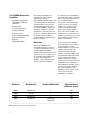
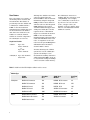
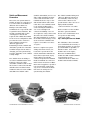
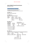
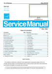
How your 3499A/B/C Test System
Benefits From Upgrading to the New
34980A Switch/Measure/Control System
Application Note
Add functionality, streamline your test
programs, and reduce the physical test
system size by upgrading from your
3499A/B/C to the new 34980A
Multifunction Switch/Measure Unit.
This application note will describe
differences and advantages of the
new 34980A as compared to the
3499A/B/C. The 34980A
Switch/Measure System masters
switching, measurement, and
control features by offering a
superior selection of switch
topologies and system control
features. A state-of-the-art DMM
has been integrated into the
34980A mainframe providing a
wide variety of measure capability.
The 34980A mainframe also
includes standard PC connections
and instrument control options for
your ease of use.
Discover the detailed advantages of
upgrading your test system using
the 34980A in this document.
34980A Mainframe, plug-in modules and terminal cards
Measurements
One of the advantages of the new
34980A is its ability to make
highly accurate test system
measurements. The integration of
a high-speed DMM into the
mainframe enhances the 34980A
switch and control system by
providing voltage, current,
temperature, frequency, and
resistance measurements without
using any of the mainframe’s
available eight slots. The DMM
conveniently generates
measurement results in selectable
engineering units. Eleven
different types of measurements
can be made and are listed on the
page 2. The 34980A time-stamped
measurement data can be stored
or displayed and analyzed as the
measurements are acquired. The
34980A also has configurable
High/Low limits on each channel
that activate an alarm if the input
signals are out of the set range.
The 34980A’s integrated DMM
saves you time and money by
reducing the number of individual
instruments required, and
additional cabling for
measurements and triggering. In
comparison, the 3499A/B/C
switch requires an external DMM
or other measurement instrument
as well as additional wiring to
provide the same functionality.
List of 34980A Measurement
Capabilities
•
Temperature measured with
Thermocouples, RTDs and
Thermistors
•
DC and AC volts
•
2- and 4-wire Resistance
•
Frequency and Period
•
DC and AC current
•
4 alarms for High/Low or both
limits for each channel
•
Digital I/O
•
Analog outputs (DAC)
The 34980A mainframe also
includes four 2-wire internal
analog buses. This is a
differentiating 34980A feature and
not included with the 3499A/B/C.
The analog buses can be used to
route measurements directly to
the internal DMM or connect the
mainframe modules to external
instruments. The analog bus can
be used to extend modules such as
the matrix switch modules, or
provide additional signal routing
between modules.
In comparison, the 3499 Family
has mainframes in three different
sizes: A, B, and C that house five,
two, and nine modules
respectively. The 3499 Family
offers a selection of 30 plug-in
modules, 13 of which are the
earlier generation HP 3488A
Switch/Control Unit modules.
Since some of the modules were
designed for the 3488, and some
modules specifically for the 3499,
there is duplicate functionality
between the modules.
Mainframes
As test systems and capability
needs expand there is a call for a
greater number of switch
channels within one system. The
34980A switch modules are
designed for high switching
channel count. The 34980A eightslot mainframe fully loaded with
2-wire multiplexer modules
houses a total switch channel
count of 560. The 3499C nine-slot
mainframe fully loaded with 2wire multiplexer modules houses
a total of 360 switch channels.
For a quick summary of the
maximum switch channel count
for the switch systems
mainframes, see Table 1.
The 34980A Multifunction
Switch/Measure Unit consists of
an eight-slot mainframe with an
optional DMM. The DMM is
mounted directly behind the front
panel so it does not require any of
the available eight module slots.
A choice from 19 different
modules can be plugged directly
into the eight-slot mainframe.
Mainframe
Mainframe Size
Number of Module Slots
Maximum Number
of Channels (2-wire)
34980A
Full Rack, 3U
8
560
3499B
Rack, 2U
2
80
3499A
Half Rack, 2U
5
200
3499C
Full Rack, 5U
9 (electrical)/
14 (physical)
360
Table 1. Max 2-wire Mux channel count per Mainframe
2
Modules
The 34980A implements a
superior selection of switch
topologies. The 34980A switch
topologies are similar to
3499A/B/C switch modules and
include multiplexers, matrixes,
high-power, general purpose, and
RF/microwave switches.
However, the 34980A modules
have utilized the newest switch
technology which enables a higher
density of channels per module,
and the ability to achieve the
faster scan rates with the
integrated DMM. The 34980A
offers other functionality used in
test systems and includes digital
I/O, a counter/totalizer and D/A
converters. New 34980A
functions include a FET
multiplexer switch module, a
counter/timer and digital I/O with
pattern generator/detector along
with digital I/O and D/A
converters. The 34980A RF and
microwave switch drivers offer
functionality for a broader range
of RF/microwave switches being
used by customers today.
The 3499A/B/C does provide a
selection of optics switching
which is not available with the
34980A. Table 2 shows the
34980A and 3499A/B/C system
modules organized by switch
and/or measurement type. It is
easy to compare and upgrade
from the 3499A/B/C switch
modules to the new 34980A
switch modules as well as add
new switch, measurement and
control capabilities.
Benefits of the new 34980A
modules vs 3499A/B/C modules
•
Increased channel count per
module with the same switch
reliability
•
Increased drivability for
various RF/uWave switches
•
High Speed FET multiplexer
•
Reed Matrix switch
•
Switch/attenuator driver
•
Counter/Timer
•
High Speed Digital I/O with
memory
•
Analog output with waveform
capabilities
•
Breadboard module
with +5V, +12V
With so many different types of
switch modules to choose from,
you can easily identify the
modules from Table 2 that
provide the best solution to meet
your test application needs. For
detailed module specifications,
please refer to the product data
sheets available at these web
locations:
http://www.agilent.com/find/34980A
and
http://www.agilent.com/find/3499
3499A/B Mainframe and plug-in modules
3
Table 2. Direct comparison of 34980A and 3499 modules
Module Type
Multiplexer
General Purpose
Matrix
Digital I/O
Multifunction
34980A
34921A 40 Ch armature 300V 1A
34922A 70 Ch armature 300V 1A
34923A 40 Ch reed 200V .5A
34924A 70 Ch reed 80V .5
34925A 40 Ch FET +/-80V .5A
34937A 28 Ch, 1A and 4 Ch, 5A
34938A 20 Ch, 5A
34931A Dual 4x8 armature 300V 1A
34932A Dual 4x16 armature300V 1A
34933A Dual 4x8 reed 80V .5A
See multifunction 34950A, 34952A
34952A 32-bit Digital I/O with 2 Ch
DAC and Counter/Timer
34950A 64-bit Digital I/O with Pattern
Generator/Detector
Fiber-Optic Multiplexer
RF & Microwave
DAC
Breadboard
4
34941A Quad 1x4 RF 1.5G 50Ω, SMA
34946A 4G/20G 50Ω, 2 SPDT SMA
(N1810TL)
34947A 4G/20G 50Ω, 3 SPDT, SMA
(N1810UL)
34942A Quad 1x4 RF 1.5G 75Ω, mSMB
34945A uwave Switch/Attn Driver
32 SPDT or 8 attenuators
The following µwave switches and
attenuators are supported with
the distribution1 boards;
N181x series SPDT switches
876X series SPDT switches
87104x/106x multi-port switches
87606x series matrix switches
8722x transfer switches
849x series attenuators
8490x series attenuators
Generic screw terminal connections
Third-party switches (screw terminals)
34951A Quad 16-bit D/A Converter
34959A +12 V, +5 V
3499A/B/C
N2260A 40 Ch armature 200V 1A
N2266A 40 Ch reed 200V .5A
N2270A 10 Ch 1000V 1A
44470A 10 Ch armature 250V 2A
44470D 20 Ch armature 250V 2A
N2261A 40 Ch
N2267A 8 Ch, 8A
44471A 10 Ch
44471D 20 Ch
44477A 7 Ch SPDT (Form C)
N2262A 4x8 armature 200V 1A
44473A 4x4 armature 250V 2A
N2263A
44474A
N2264A
N2265A
N2269A
32-bit TTL
16-bit TTL
12 GP, 3 GP 5A, 16-bit Dig I/O
4x4 matrix, 16-bit Dig I/O
2 DAC, 16-bit Dig I/O
N2280A Quad 1x2
N2281A Dual 1x4
N2282A Single 1x8
N2268A Dual 1x4 3.5G 50Ω
N2272A Single 1x9 1.0G 50Ω
N2276A Dual 1x6 20G 50Ω
(87106B/4B)
44472A Dual 1x4 300M 50Ω
44478A Dual 1x4 1.3G 50Ω
44476A Triple 1x2 18G 50Ω
(8762B)
44478B Dual 1x4 1.3G 75Ω
N2276B Relay driver (2 switches)
Choose from switches;
87104A/B/C
87106A/B/C
also drive two external attenuators
84904/6/7/K/L
44476B Relay driver (2 switches)
Choose from switches;
8762A/B/C/F
8763B/C
8764B/C
See multifunction
44475A 5.5
User Interface
The 34980A offers the most
modern instrument I/O options for
interfacing a controller PC with the
switch system: GPIB, USB and
LAN. All three Input/Output
interface connections come
standard with the 34980A
mainframe. If you choose to modify
or upgrade your test system I/O,
the 34980A is system ready.
You can also easily control the
34980A without connecting to a PC
by pressing the front-panel buttons,
an advantage when first setting up
or troubleshooting a system.
Upgrading your test system from
using the 3499A/B/C GPIB to the
34980A GPIB, or newer USB or
LAN is quick and easy. If you have
used I/O Config from the Agilent
I/O Libraries to set your GPIB
instrument connection, you would
use the same I/O Config to set up
your LAN or “TCPIP” instrument
connection. Retrieve the LAN,
TCPIP address from your
instrument and enter it into I/O
Config. When you address your
instrument in a program, it will
look similar to; TCPIP0::9::INSTR.
For more information on
connecting to Agilent instruments
you can access the Agilent
Technologies USB/LAN/GPIB
Interfaces Connectivity Guide at
www.agilent.com/find/connectivity
With LAN, the instrument can be
located closer to the device under
test without worrying about the
distance to the PC. A USB to
instrument connection is even
easier. The computer
automatically detects instruments
that are USB ready. If you are
currently using the 3499A/B/C
RS232 interface, it is recommended
to upgrade to the 34980A GPIB,
USB or LAN interface to achieve
optimal data transfer rates.
Instrument Control
(Programming)
The 34980A and 3499A/B/C can
both be controlled locally from the
front panel, or by sending either
instrument or driver commands
from a PC for remote control. The
34980A’s instrument commands
and drivers are based on modern
standards such as SCPI (standard
commands for programmable
instruments) and IVI-C and IVI
COM drivers. The SCPI instrument
commands of the 34980A are
similar to the 3499A/B/C’s but
they are not interchangeable. A
comparison of the commands is
provided in appendix A. The
34980A's IVI-C and IVI-COM
drivers are similar to Plug & Play
drivers, the 3499A/B/C's Plug &
Play driver for example, but
include improvements. The IVI
(Interchangeable Virtual
Instruments) driver specification
was built upon the Plug&Play
driver specification but adds the
capabilities provided by the
Microsoft ActiveX technologies
which simplify instrument
interchangeability, and product
performance. The 34980A also
includes many new commands for
the operation of the embedded
DMM. A 34980A Web interface
provides a new easy way to
communicate via LAN with the
instrument.
Table 3 shows a summary of the
programming control options
available for the 3499A/B/C and the
34980A. There is similarity between
the instrument commands, however,
the 34980A has evolved to use the
most modern and widely accepted
instrument command standards.
Table 3. Control Options for 3499A/B/C and 34980A
3499A/B/C
34980A
Front Panel Buttons
3488 Legacy Commands
SCPI Commands
Plug & Play driver
IVI COM driver
IVI-C driver
LabVIEW driver
Web Interface
5
Listed below are each of the many ways available to communicate and
control the 34980A, the communication options and their description
Web Page Interface
The 34980A comes with a built-in
detailed instrument web page that
allows you to remotely connect and
communicate with the mainframe
and installed modules. You
establish a LAN connection, either
directly between the 34980A and
PC, or from the 34980A to an
existing Local Area Network. The
instrument Web page resides on
the 34980A and can be accessed
using a standard web browser such
as Netscape or Internet Explorer
on a PC. Just type the IP address
into the web browser. The web
interface allows you to select any of
the installed modules and view the
current configuration, change
settings, make measurements, and
makes it easy to troubleshoot or
debug the switch/measure system.
The instrument web interface also
allows you to check the current
status of the instrument by viewing
the error queue, calibration status
and the accumulated module
switch closures.
Web interface display for 34921A MUX Switch module
Web interface display of scanned measurements
6
SCPI Commands
The 34980A can be programmed
using SCPI commands or the IEEE
standard commands.
Configuration, measurements and
system control of the mainframe
and modules are easily achieved
using these instrument commands.
One difference between
instrument commands for the
3499A/B/C and the 34980A relates
to addressing specific channels in
the system. Table 4 shows an
example difference in 3499A/B/C
switch control commands
compared to 34980A commands.
Notice the 34980A uses four digits
to address the module slot number
and channel(s) rather than only
three digits as the 3499A/B/C
uses. Also, for the 3499A/B/C the
[ROUTe] in the command
structure is optional, where with
the 34980A it is required.
The 34980A offers new
measurement and module
capabilities such as counter/timer
and digital I/O with pattern
generator/detector that use
commands unique to their
functionality. Appendix A includes
a list of the 34980A and 3499A/B/C
commands as well as direct
comparisons of the commands.
IVI-C, IVI COM and LabVIEW
instrument drivers
34980A IVI-C, IVI COM and
LabVIEW instrument drivers are
available for simplified
programming. If you currently
program using Plug&Play drivers,
the IVI-C driver is similar and can
be used to program in the same
way. The IVI COM driver conforms
to the most modern IVI COM
instrument driver standard and
can be used in any programming
environment. LabVIEW
programmers are able to use the
34980A LabVIEW instrument
driver for their graphical
programming environment.
Table 4. Command comparisons
34980A
3499A/B/C
Close channel 10 on the module in slot 3
ROUTe:CLOS (@3010)
[ROUTe:]CLOS (@310)
Scan channels 0 through 40 on the module in slot 1
ROUTe:SCAN (@1001:1040)
[ROUTe:]SCAN (@100:140)
Example program. 34980A SCPI commands in VEE
7
Scan Feature
The scan feature is a sequence of
alternating switch closures and
measurements. This feature is
provided by both the 34980A and
a 3499A/B/C combined with a
DMM or other measurement
instrument. The 34980A increases
the measurement scan abilities
and offers more than twice the
number of scanned channels
within one scan list compared to
the 3499A/B/C as seen here.
Single Scan List Size:
34980A
Up to 560
2-wire channels
or
Up to 640
1-wire channels
3499A/B/C Up to 200 channels
and/or bits
Although the 34980A scan feature
can be used with either the
internal DMM or with an external
instrument, using the integrated
DMM provides a faster and more
efficient scan rate. The integrated
DMM eliminates the need for
external instrument triggers and
wiring. The 3499A/B/C scan list
requires the use of instrument
triggers to work with an external
DMM or other measurement
instrument. Each switch module is
rated with individual switch scan
rates. A comparison of the scan
rates for both systems Multiplexer
and Matrix switch modules is
shown in Table 5 below.
The 3499A/B/C cannot store
readings but does offer more scan
configurability. For example,
once a 3499A/B/C scan list is set
up, the user can select an arm
source, a trigger source, the
number of sweeps, and the delay
time for each individual channel
within the scan list.
Another advantage the 34980A
system has over the 3499A/B/C
system is its ability to store
measurement readings. When the
34980A internal DMM is used, up
to 500,000 time stamped readings
can be stored in volatile memory.
Table 5. 34980A and 3499A/B/C Multiplexer & Matrix module scan rates
Module Type
Multiplexer
Matrix
8
34980A
Modules
Scan Rate
Ch/s
3499A/B/C
Modules
Scan Rate
Ch/s
34921A 40 Ch armature
100
N2260A 40 Ch armature
80
34922A 70 Ch armature
100
N2266A 40 Ch reed
350
34923A 40 Ch reed
500
N2270A 10 Ch
100
34924A 70 Ch reed
500
44470A 10 Ch armature
43
34925A 40 Ch FET
1000
44470D 20 Ch armature
43
34931A Dual 4x8 armature
100
N2262A 4x8 armature
80
34932A Dual 4x16 armature
100
44473A 4x4 armature
43
34933A Dual 4x8 reed
500
Monitor Feature
The 34980A monitor feature
allows you to monitor readings
acquired by the switch/measure
system. You can also monitor
readings acquired with the
34980A internal DMM. To
monitor a measurement from the
front panel, simply select the
channel and press either the
Measure [DMM] or [Channel]
button to see a continually
updated channel output or state
on the front display. For
programs, use the
ROUTe:MONitor:DATA?
Command. The command reads
the data from the channel
currently selected by the Monitor
function. One reading is displayed
for each monitor command. The
Web interface can also be used to
monitor a channel measurement.
The 3499A/B/C monitor feature
allows users to continuously
monitor a selected switch or
module status from the front
display. A channel monitor can
be set up using the front panel
buttons or instrument commands.
The 3499A/B/C monitor output
can be a specific switching
channel, a digital I/O port or the
state of all switches or digital I/O
on one plug-in module. The
3499A/B/C allows a single
channel to be monitored
continuously even during an
instrument scan.
Stored State Feature
The 34980A is also able to
store/recall up to six (0 through
5) instrument setups. A stored
setup state can be automatically
recalled at any time, even during
a power up state. The stored
state feature contains the state of
the plug-in modules including
channel configurations, scanning
setups, alarm values, and Mx + B
scaling values. Location 0 is
typically used for the Factory
Reset and power down state, but
can also be programmed with a
new setup.
The 3499A/B/C is able to store
and recall up to 50 instrument
setup states with revision 4.0.
The instrument setups include the
status of relay channels, and/or
the static digital I/O state, module
configuration, and scanning
setups (scan lists, arm count, arm
source, etc.). The 3499A/B/C is
not able to automatically power
up in a stored state.
9
Switch and Measurement
Connections
Most often, test systems must be
flexible enough to be easily moved
to a new location or modified for
different devices under test.
Having a removable wiring
terminal block or a pre-wired cable
is optimal in these situations. The
module’s terminal and/or cable
can simply be removed and
replaced with a different terminal
for the new test configuration. This
prevents the need to rewire the
same terminal each time for
different applications.
Fortunately, both the 34980A and
3499A/B/C provide the removable
terminals and pre-wired cables so
changing your test system wiring
from the 3499A/B/C to the 34980A
is fairly simple.
The 34980A offers the ability to
use either standard Dsub 50 and
Dsub 78 connectors/cables,
detachable terminal cards or mass
interconnect connections. The RF
and Microwave modules include
standard connectors such as SMA
and SMB. The 34980A cables
34980A Modules and Std DSub 50/78 connectors
10
(Dsub50 and Dsub78) are low cost
and readily available from many
sources. The detachable screw
terminal blocks are easy to wire
and include built-in cable strain
relief. The screw terminals attach
to the switch modules with a
secure latching mechanism for
ease of use and improved
connection reliability. No tools
are required to easily connect and
disconnect the wired terminals.
The 3499 terminals are secured to
the module and housing by screws
at the end of the terminals and
require a screwdriver to remove
or replace.
For more complex test system
wiring, mass interconnect (one
location in a system where the
switch, instruments and DUT are
interconnected) is made easy by
using solutions provided by
connection experts. The standard
Dsub 50 and Dsub 78 connectors
make it faster and easier for Mass
Interconnect suppliers to provide a
test system wiring solution. The
easy to use connections facilitate
time and cost savings for test
systems using the 34980A.
The 34980A terminal wiring and
cables are different from that of
the 3499A/B/C. However, they
offer a better solution to test
system interface due to the use of
highly reliable standard
connectors and low cost cables.
Refer to Table 2 for the modules
that have optional terminal
blocks or the 34980A data sheet
for specific module wiring
connection details:
http://www.agilent.com/find/34980A.
The 3499A/B/C offers removable
screw terminal blocks for many of
the modules and also an option for
pre-wired DIN96 to quad D25, or
dual D50 cables. Some of the
modules such as the Optics,
Microwave and RF modules
include the SMA or BNC terminals
for application specific
connections. Refer to Table 2 for
modules that include terminals.
3499A/B/C Modules and Terminals
Summary
Although the 3499A/B/C
Switch/Control system has been a
great addition to many test
systems, the new 34980A now
offers an even better module
selection plus measurement
capability, standard PC
connections for communication,
and is easy to connect to modules.
The wide offering of plug-in
modules for the 34980A enables
you to select a configuration for
your specific application needs.
Features that differentiate
new 34980A:
•
FET switches for long life, high
speed measurement scans and the
latest in technology Armature and
Reed relays for both Multiplexer
and Matrix switching
•
Analog bus for joining modules,
connecting to external instruments,
accessing internal DMM.
•
Up to 5A general purpose switch
addresses the most common high
power and device control
applications.
•
Bread board with +12V and +5V
supplies for more design flexibility.
•
Integrated DMM and measurement
capability save you time versus
programming with an external
measurement instrument, and
money with the switch and DMM
in one instrument.
•
Up to 1000 readings/sec scan rate
for higher speed applications
•
GPIB and new USB and LAN
interfaces provide flexibility, lower
cost, higher data transfer rates,
and are the emerging trend of
choice of interfaces.
•
Up to 70 Ch per module offer
higher density solutions
•
Standard module connectors &
cables offer an easy connection
and for Mass interconnect
solutions.
•
Screw terminals with latching
mechanisms are easy to remove
and replace and securely fastened
when in use.
•
Web interface to quickly and easily
test or debug the test system
switching.
•
Large memory buffer for acquired
measurements.
There are a few specialized
features the 3499 offers that are
not available with the new
34980A. It is good to be aware of
the differences as you upgrade to
the newer system.
3499A/B/C differentiating features
•
4 dig I/O ports built into mainframe
doesn’t require a module
•
Fiber-Optic modules
•
1000V multiplexer module
The 34980A Switch/Measure unit
can be used in the same
applications as the 3499A/B/C
including design verification,
functional test and data
acquisition applications. It can
also be used in many new
applications such as for data
logging, as a data acquisition
system and/or as a switch system.
It can even provide a solution for
applications requiring transducerbased measurements such as
thermocouple or strain. The
34980A offers a great switch,
measurement and test system
control solution at a great value.
11
Appendix A – Command Reference/Comparison
34980A Commands
ABORt
3499A/B/C Commands
ABORt
ARM
:SOURce
BUS|EXTernal|IMMediate|TIMer|MIX/HOLD
:SOURce?
:COUNt
<number>|MIN| MAX
:TIMer
<seconds>|MIN|MAX
:TIMer?
CALCulate
:AVERage:AVERage?
:AVERage:CLEar
:AVERage:COUNt?
:AVERage: MAXimum?
:AVERage:MAXimum:TIME?
:AVERage:MINimum?
:AVERage:MINimum:TIME?
:AVERage:PTPeak?
:LIMit:LOWer
:LIMit:LOWer?
:LIMit:LOWer:STATe
:LIMit:LOWer:STATe?
:LIMit:UPPer
:LIMit:UPPer?
:LIMit:UPPer:STATe
:LIMit:UPPer:STATe?
:SCALe:GAIN
:SCALe: GAIN?
:SCALe:OFFSet
:SCALe:OFFSet?
:SCALe: OFFSet:NULL
:SCALe: STATe
:SCALe: STATe?
:SCALe:UNIT
:SCALe: UNIT?
CALibration
:COUNt?
:LFRequency?
:SECure:CODE
SECure:STATe
:SECure:STATe?
:SETup
:SETup?
:STRing
:STRing?
:VALue
:VALue?
CALibration?
CONFigure
CONFigure
:EXTernal[:TRIGger]
:SOURce
:SOURce?
[:OUTPut]
0|1|OFF|ON
[:OUTPut]?
12
34980A Commands (cont’d.)
:CURRent:AC
:CURRent[:DC]
:DIGital:STATe
:DIGital:WIDTh
:FREQuency
:FRESistance
:PERiod
:RESistance
:TEMPerature
:TOTalize
[:VOLTage]:AC
[:VOLTage][:DC]
CONFigure?
DATA
:LAST?
:POINts:EVENt:THReshold
:POINts:EVENt:THReshold?
:POINts?
:REMove?
DIAGnostic
:DMM:CYCLes:CLEar
:DMM:CYCles?
:RELay CYCles:CLEar
:RELay:CYCLes?
3499A/B/C Commands (cont’d.)
DIAGnostic
[:RELay]:CYCLes:CLEar
[:RELay]:CYCLes?
[:RELay]:CYCLes:CLEar
[:RELay]:CYCLes?
[:RELay]:CYCLes:MAX?
:DISPlay[:INFOrmation]
:DISPlay:STATe?
:MONitor
:MONitor?
:SPEEK?
:SPOKE
DISPlay
[:STATe]
[:STATe]?
:TEXT
:TEXT ?
:TEXT:CLEar
FETCh?
FORmat
:BORDer
:READing:ALARm
:READing:ALARm?
:READing:CHANnel
:READing:CHANnel?
:READing:TIME
:READing:TIME?
:READing:TIME:TYPE
:READing:TIME:TYPE?
:READing:UNIT
:READing:UNIT?
INITiate
INSTrument
:DMM:CONNect
:DMM:DISConnect
:DMM:INSTalled?
:DMM[:STATe]
:DMM[:STATe]?
MEASure
FETCh?
INITiate
13
34980A Commands (cont’d.)
:CURRent:AC?
:CURRent[:DC]?
:DIGital[:<width>]?
:DIGital[:BYTE]:BIT?
:FREQuency?
FRESistance?
:PERiod?
:RESistance?
:TEMPerature?
:TOTalize?
[:VOLTage]:AC?
[:VOLTage][:DC]?
MEMory
:STATe:CATalog?
:STATe:DELete
:STATe:NAME
:STATe:NAME?
:STATe:RECall:AUTO
:STATe:RECall:AUTO?
:STATe:RECall:SELect
:STATe:RECall:SELect?
:STATe:VALid?
OUTPut
:ALARm<n>:CLEar
:ALARm:MODE
:ALARm:MODE?
:ALARm:SLOPe
:ALARm: SLOPe?
:ALARm<n>:SOURce
:ALARm<n>:SOURce?
[:STATe]
R?
READ?
ROUTe
:CHANnel:ADVance:SOURce
:CHANnel:ADVance:SOURce?
:CHANnel:DELay
:CHANnel:DELay?
:CHANnel:DELay:AUTO
:CHANnel:DELay:AUTO?
:CHANnel:FWIRe
:CHANnel:FWIRe?
:CHANnel:LABel:CLEar:MODule
:CHANnel:LABel[:DEFine]
:CHANnel:VERify[:STATe]
:CLOSe
:CLOSe?
:MODule:BUSY?
:MODule:WAIT
:MONitor[:CHANnel]
:MONitor[:CHANnel]ENABle
:MONitor:DATA?
:MONitor:MODE
:MONitor:STATe
:MONitor:STATe?
:OPEN
:OPEN?
:OPEN:ABUS
:OPEN:ALL
:OPERation:OVERlap[ENABle]
14
3499A/B/C Commands (cont’d.)
[ROUTe:]
[CHANnel:]DELay
[CHANnel:]DELay?
CLOSe
CLOSe?
OPEN
OPEN?
34980A Commands (cont’d.)
:SCAN
:SCAN:ADD
:SCAN:REMove
:SCAN:SIZE?
3499A/B/C Commands (cont’d.)
SCAN:SIZE?
SCAN[:LIST]?
SCAN[:LIST]
SCAN CLEar
CPAir
CPAir?
FUNCtion
FUNCtion?
SAMPle
:COUNt
:COUNt?
SENSe
SENSe
:CURRent:AC
:BANDwidth
:BANDwidth?
:RANGe
:RANGe?
:RANGe:AUTO
:RANGe:AUTO?
:CURRent[:DC]
:APERture:ENABled?
:APERture
:NPLC
:NPLC?
:RANGe
:RANGe?
:RANGe:AUTO
:RANGe:AUTO?
:RESolution
:RESolution?
:ZERO:AUTO
:DIGital:DATA[:<width>]?
:DIGital:DATA[BYTE]:BIT?
:FREQuency
:APERture
:APERture?
:RANGe:LOWer
:RANGe:LOWer?
:VOLTage:RANGe
:VOLTage:RANGe?
:VOLTage:RANGe:AUTO
:VOLTage:RANGe:AUTO?
:FRESistance
:APERture
:APERture:ENABled?
:NPLC
:NPLC?
:OCOMpensated
:OCOMpensated?
:RANGe
:RANGe?
:RANGe:AUTO
:DIGital
:DATA:BIT?
:DATA[:<BYTE|WORD|LWORD>[:VALue]?
:DATA[:<BYTE|WORD|LWORD>:BLOCK?
:DATA[:<BYTE|WORD|LWORD>:TRACE
:TRACe[:DATA]?
15
34980A Commands (cont’d.)
:RANGe:AUTO?
:RESolution
:RESolution?
:ZERO:AUTO
:FUNCtion
:FUNCtion?
:PERiod:APERture
:PERiod:VOLTage:RANGe
:VOLTage:RANGe?
:VOLTage:RANGe:AUTO
:VOLTage:RANGe:AUTO?
:PERiod:ZERO:AUTO
:RESistance:APERture
:APERture?
:ALPERture:ENABled?
:NPLC
:NPLC?
:OCOMpensated
:OCOMpensated?
:RANGe
:RANGe?
:RANGe:AUTO
:RANGe:AUTO?
:RESolution
:RESolution?
:ZERO:AUTO
:TEMPerature:ABERture
:APERture:ENABled?
:NPLC
:NPLC?
:TRANsducer:Tcouple:IMPedance:AUTo
:Tcouple:CHECk
:RJUNction
:RJUNction:TYPE
:TYPE
:TRANsducer:TYPE
:FRTD:RESistance
:FRTD:TYPE
:RTD:RESistance
:RTD:TYPE
:THERmistor:TYPE
:ZERO:AUTO
:RJUNction?
:TOTalize:CLEar:IMMediate
:DATA?
:SLOPe
:THReshold[:MODE]
:TYPE
:VOLTage
:AC:BANDwidth
:AC:BANDwidth?
:AC:RANGe
:AC:RANGe?
:AC:RANGe:AUTO
:AC:RANGe:AUTO?
[:DC]:APERture
[:DC]:APERture?
[:DC]:APERture:ENABled?
[:DC]:IMPedance:AUTO
[:DC]:NPLC
16
3499A/B/C Commands (cont’d.)
34980A Commands (cont’d.)
[:DC]:NPLC?
[:DC]:RANGe
[:DC]:RANGe?
[:DC]:RANGe:AUTO
[:DC]:RANGe:AUTO?
[:DC]:RESolution
[:DC]RESolution
[:DC]:ZERO:AUTO
[:DC]:ZERO:AUTO?
SOURce
:CURRent[:LEVel]
:CURRent[:LEVel]?
3499A/B/C Commands (cont’d.)
SOURce
:DIGital
:MODE
:MODE?
:CONTrol:POLarity
:CONTrol:POLarity?
:FLAG:POLarity
:FLAG:POLarity?
:IO:POLarity
:IO:POLarity?
:DATA[:<BYTE|WORD|LWORD>:POLarity
:DATA[:<BYTE|WORD|LWORD>:POLarity?
:DATA:BIT
:DATA[:<BYTE|WORD|LWORD>[:VALue]
:DATA[:<BYTE|WORD|LWORD>:BLOCK
:DATA[:<BYTE|WORD|LWORD>:TRACE
:TRACe:DEFine
:TRACe:DEFine?
:TRACe:CATalog?
:TRACe[:DATA]
:TRACe:DELete[:NAME]
:TRACe:DELete:ALL
:DIGital:DATA[:<width>]
:DIGital:DATA[BYTE]:BIT
:DIGital:STATe?
:FUNCtion:CLOCk:EXTernal:DIVisor
:CLOCk[INTernal]:PERiod
:CLOCk:SOURce
:CURRent:GAIN
:CURRent:OFFSet
:ENABle
:FREQuency
:HALT
:STATus?
:TRACe:NCYCles
:TRACe[NAME]
:TRACe:SINDex
:TRIGger:IMMediate
:TRIGger:SOURce
:VOLTage:GAIN
:VOLTage:OFFSet
:MODE
:MODE?
:VOLTage[:LEVel]
:VOLTage[:LEVel]?
STATus
STATus
:ALARm:CONDition?
:ALARm:ENABle
17
34980A Commands (cont’d.)
3499A/B/C Commands (cont’d.)
:ALARm:ENABle?
:ALARm[:EVENt]?
:MODule:ENABle
:MODule:EVENt?
:MODule:SLOT[n]:CONDition?
:MODule:SLOT[n]:ENABle
:MODule:SLOT[n][:EVENt]?
:OPERation:CONDition?
:OPERation:ENABle
:OPERation:ENABle?
:OPERation[:EVENt]?
:PRESet
:QUEStionable:CONDition?
:QUEStionable:ENABle
:QUEStionable:ENABle?
:QUEStionable[:EVENt]?
SYSTem
:ABUS:INTerlock:SIMulate
:ALARM?
:BEEPer
:BEEPer:STATe?
:CDEScription?
:COMMunicate:ENABle
:GPIB:ADDRess
:LAN:AUTOip
:LAN:BSTatus?
:LAN:CONTrol?
:LAN:DHCP
:LAN:DNS
:LAN:DOMain
:LAN:GATEway
:LAN:HISTory?
:LAN:HISTory:CLEar
:LAN:HOSTname
:LAN:IPADdress
:LAN:KEEPalive
:LAN:MAC?
:LAN:SMASk
:LAN:TELNet:PROMpt
:LAN:TELNet:WMESsage
:CPON
:CTYPe?
:DATE
:DATE?
:ERRor?
:KLOCk:EXCLude
:KLOCk:EXCLude?
:KLOCk[:STATe]
:KLOCk[:STATe]?
:LOCK:OWNer?
:LOCK:RELease
:LOCK:REQuest?
:MODule?
:MODule:PFAil:JUMPer:AMP5?
:MODule:WIRE:MODE
:MODule:TEMPerature?
:PRESet
:SECurity:IMMediate
:TIME
18
:OPERation:CONDition?
:OPERation:ENABle
:OPERation: ENABle?
:OPERation[:EVENt]?
:PRESet
SYSTem
:CPON
:CTYPe?
:ERRor?
34980A Commands (cont’d.)
3499A/B/C Commands (cont’d.)
:TIME?
:TIME:SCAN?
:VERSion?
:VERSion?
:LOCal
:REMote
:RWLock
:STATe:DELete
TRACe:CATalog?
[:DATA]
[:DATA]:DAC
[:DATA]:FUNCtion
:DELete:ALL
:DELete[:NAME]
:FREE?
:POINts?
TRIGger
TRIGger
[:IMMediate]
:COUnt
:COUNt?
:DELay
:DELay?
:DELay:AUTO
:DELay:AUTO?
:SOURce
:SOURce?
:TIMer
:TIMer?
:SOURce
:SOURce?
:TIMer
TIMer?
UNIT
:TEMPerature
:TEMPerature?
IEEE-488.2 Common Commands
*CLS
*ESE *ESE?
*ESR?
*IDN?
*OPC *OPC?
*PSC *PSC?
*RCL
*RST
*SAV
*SRE *SRE?
*STB?
*TRG
*TST?
*WAI
IEEE-488.2 Common Commands
*CLS
*OPC *OPC?
19
www.agilent.com/find/emailupdates
www.agilent.com
Agilent Technologies’ Test and Measurement
Support, Services, and Assistance
Agilent Technologies aims to maximize the value
you receive, while minimizing your risk and
problems. We strive to ensure that you get the
test and measurement capabilities you paid for
and obtain the support you need. Our extensive
support resources and services can help you
choose the right Agilent products for your
applications and apply them successfully. Every
instrument and system we sell has a global
warranty. Support is available for at least five
years beyond the production life of the product.
Two concepts underlie Agilent’s overall support
policy: “Our Promise” and “Your Advantage.”
Our Promise
Our Promise means your Agilent test and
measurement equipment will meet its advertised
performance and functionality. When you are
choosing new equipment, we will help you with
product information, including realistic
performance specifications and practical
recommendations from experienced test
engineers. When you use Agilent equipment, we
can verify that it works properly, help with
product operation, and provide basic
measurement assistance for the use of specified
capabilities, at no extra cost upon request. Many
self-help tools are available.
Your Advantage
Your Advantage means that Agilent offers a
wide range of additional expert test and
measurement services, which you can purchase
according to your unique technical and business
needs. Solve problems efficiently and gain a
competitive edge by contracting with us for
calibration, extra-cost upgrades, out-of-warranty
repairs, and onsite education and training, as
well as design, system integration, project
management, and other professional
engineering services. Experienced Agilent
engineers and technicians worldwide can help
you maximize your productivity, optimize the
return on investment of your Agilent
instruments and systems, and obtain
dependable measurement accuracy for the life
of those products.
Get the latest information on the products and
applications you select.
Agilent T&M Software and Connectivity
Agilent’s Test and Measurement software and
connectivity products, solutions and developer
network allows you to take time out of
connecting your instruments to your computer
with tools based on PC standards, so you can
focus on your tasks, not on your connections.
Visit www.agilent.com/find/connectivity for
more information.
By internet, phone, or fax, get assistance with
all your test & measurement needs
Online assistance:
www.agilent.com/find/assist
Phone or Fax
United States:
(tel) 800 829 4444
Canada:
(tel) 877 894 4414
(fax) 905 282 6495
China:
(tel) 800 810 0189
(fax) 800 820 2816
Europe:
(tel) (31 20) 547 2323
(fax) (31 20) 547 2390
Japan:
(tel) (81) 426 56 7832
(fax) (81) 426 56 7840
Korea:
(tel) (82 2) 2004 5004
(fax) (82 2) 2004 5115
Latin America:
(tel) (305) 269 7500
(fax) (305) 269 7599
Taiwan:
(tel) 0800 047 866
(fax) 0800 286 331
Other Asia Pacific Countries:
(tel) (65) 6375 8100
(fax) (65) 6836 0252
Email: [email protected]
Product specifications and descriptions in this
document subject to change without notice.
© Agilent Technologies, Inc. 2004
Printed in USA October 5, 2004
5989-1581EN