1
SEARS
OWNER'S
MANUAL
MODEL NO.
944.627592
CRAFTSMAN+
Caution:
Read and follow
all Safety Rules
and Instruct,ons
Before Operating
This Equipment
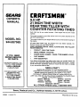
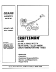
9.0 HP
21 INCH TINE WIDTH
REAR TINE TILLER WITH
COUNTER ROTATING TINES
•
•
•
•
•
Sears, Roebuck
Assembly
Operation
Customer Responsibilities
Service and Adjustments
Repair Parts
and Co., Hoffman Estates, IL 60179 U.S.A.
Safe
Operation
SAFETY
RULESPowered
for Walk-Behind
Practices
TRAINING
•
•
Read the Owner's Manual carefully. Be thoroughly
familiar with the controls and the proper use of the
equipment. Know how to stop the unit and disengage
the controls quickly.
Never allow children to operate the equipment: Never
allow adults to operate the equipment without proper
instruction.
Keep the area of operaUon clear of all persons, particularly small children, and pets.
•
•
•
Thoroughly inspect the area where the equipment isto
be used and remove all foreign objects.
Disengage all clutches and shift into neutral before
starting the engine (motor);
Do not operate the equipment without wearing adequate outer garments. Wear footwear that will improve footing on slippery surfaces.
Handle fuel with care; it is highly flammable.
Use an approved fuel container.
Never add fuel to a running engine or hot engine.
Fill fuel tank outdoors with extreme care. Never fill fuel
tank indoors.
Replace gasoline cap securely and clean up spilled
fuel before restarting.
Use extension cords and receptacles as specified by
the manufacturer for all units with electric drive motors
or electric starting motors,
Never attempt to make any adjustments while the
engine (motor) is running (except where specifically
recommended by manufacturer).
•
•
•
•
•
•
•
•
•
•
•
•
•
•
.... MAINTENANCE
•'
•
•
•
•
•
•
•
AND
STORAGE
Keep machine, attachments, and accessories'in safe
working condition.
Check shear pins, engine mounting bolts, and other
bolts at frequent intervals for proper tightness to be
sure the equipment is in safe working condition.
Never stora the machine with fuel in the fueltank inside
a building where ignition sources are present, such as
hot water and space heaters, clothes dryers, and the
like. Allow the engine to cool before storing in any
enclosure.
Always refer to the operator's guide instructions for
important details if the tiller is to be stored for an
extended period.
•
•
•
- IMPORTANT
-
CAUTIONS,
IMPORTANTS,
AND NOTES ARE A MEANS
OF ATTRACTING
ATTENTION
TO IMPORTANT
OR
CRITICAL INFORMATION
IN THIS MANUAL.
OPERATION
•
•
&
Tillers
Never operate the tiller without proper guards, plates,
or other safety protective devices in place.
Keep children and pets away.
Do not overload the machine capacity by attempting to
till too deep at too fast a rate.
Never operate the machine at high speeds on slippery
surfaces. Look behind and use care when backing.
Never allow bystanders near the unit.
Use only attachments and accessories approved by
the manufacturer of the tiller.
Never operate the tiller without good visibility or light.
Be careful when tilling in hard ground. The tines may
catch in the ground and propel the tiller forward. If this
occurs, let go of the handlebars and do not restrain the
machine.
•
•
PREPARATION
Rotary
Do not put hands or feet near or under rotating parts.
Exercise extreme caution when operating on or crossing gravel drives, walks, or roads. Stay alert for hidden
hazards or traffic. Do not carry passengers.
After striking a foreign object, stop the engine (motor)
remove the wire from the spark plug, thoroughly inspect the tiller for any damage, and repair the damage
before restarting and operating the tiller.
Exercise caution to avoid slipping or falling.
If the unit should start to vibrate abnormally, stop the
engine (motor) and check immediately for the cause.
Vibration is generally a warning of trouble.
Stop the engine (motor) when leaving the operating
position.
Take all possible precautions when leaving the machine unattended.
Disengage the tines, shift into
neutral, and stop the engine.
Before Cleaning, repairing, or inspecting shut off the
engine and make certain all moving partshave stopped.
Disconnect the spark plug wire, and keep the wire
away from the plug to prevent accidental starting.
Disconnect the cordon electric motors.
Do not run the engine indoors; exhaust fumes are
dangerous.
IMPORTANT, USED TO ALERT YOU THAT THERE IS A
POSSIBILITY OF DAMAGING THIS EQUIPMENT.
NOTE:
Gives essential information that will aid you to
better understand, incorporate, or execute a particular set
of instructions.
&
Look for this symbol to point out important safety precautions.
It means
CAUTIONllt BECOME ALERTHI YOUR
SAFETY IS INVOLVED.
i
&
2
CAUTION:
Always disconnect spark
plug wire end place wire where It cannot contact spark plug in order to prevent accidental starting when setting
up, transporting, adjusting or making
repairs.
.,
I
CONGRATULATIONS on your purchase of a Sears Tiller.
It has been designed, engineered and manufactured to
give you the best possible dependability and performance.
PRODUCT SPECIFICATIONS
Should you experience any problems you cannot easily
remedy, please contact your nearest authorized Sears
Service Center/Department. They have competent, welltrained technicians and the proper tools to service or repair
this unit.
Please read and retain this manual. The instructions will
enable you to assemble and maintain your tiller properly.
Always observe the =SAFETY RULES".
MODEL
NUMBER
HORSEPOWER:
9.0 HP
DISPLACEMENT:
19 cu. in. (31 l cc)
GASOLINE CAPACITY:
4 Quarts (3.8L)
Unleaded Regular
OIL (API-SF/SG/SH) :
CAPACITY: 44 oz.)
SAE 30 (Above 32°F)
SAE 3W-30 (Below 32°F)
SPARK PLUG :
3AP: ,030")
Champion
RJ19LM
944.627592
SERIAL
NUMBER
MAINTENANCE
DATE OF
PURCHASE
A Sears Maintenance Agreement is ava ab e on th s product. Contact your nearest Sears store for details._
THE MODEL AND SERIAL NUMBERS WILL BE
FOUND ON THE MODEL PLATE ATTACHED TO
THE TOP OF THE TRANSMISSION,
CUSTOMER
YOU SHOULD RECORD BOTH SERIAL NUMBER
AND DATE OF PURCHASE AND KEEP IN A SAFE
PLACE FOR FUTURE REFERENCE.
AGREEMENT
RESPONSIBILITIES
•
Read and observe the safety rules.
•
Follow e regular schedule in maintaining, caring for and
using your tiller.
•
Follow the instructions under the "Customer
Responsibilities"and "Storage" sections of this Owner's
Manual.
IMPORTANT:
THIS UNIT IS EQUIPPED WITH AN INTERNAL COMBUSTION
ENGINE AND SHOULD NOT BE USED ON
OR NEAR ANY UNIMPROVED
FOREST-COVERED,
BRUSH,COVERED
OR GRASS COVERED
LAND UNLESS THE
ENGINE'S EXHAUST SYSTEM IS EQUIPPED WITH A SPARK ARRESTER
MEETING APPLICABLE
LOCAL OR STATE
LAWS (IF ANY). IF A SPARK ARRESTER IS USED, IT SHOULD BE MAINTAINED
IN EFFECTIVE WORKING ORDER BY
THE OPERATOR.
IN THE STATE OF CALIFORNIA
THE ABOVE IS REQUIRED BY LAW (SECTION
4442 OF THE CALIFORNIA
PUBLIC
RESOURCES
CODE).
OTHER STATES MAY HAVE SIMILAR LAWS. FEDERAL LAWS APPLY ON FEDERAL LANDS.
SEE YOUR SEARS AUTHORIZED
SERVICE CENTER/DEPARTMENT
FOR SPARK ARRESTER.
REFER TO THE REPAIR
PARTS SECTION OF THIS MANUAL FOR PART NUMBER.
LIMITED TWO (2) YEAR WARRANTY ON CRAFTSMAN TILLER
For Two (2) years from date of purchase Sears Canada, Inc. will repair or replace at Sears option free of charge pads which are
defective as a result of matedal or workmanship.
COMMERCIAL OR RENTAL USE:
Warranty on Tiller will be thirty (30) days from date of purchase if used for commercial or rental purposes.
This Warranty does NOT cover:
1. Pre-dellvery set-up.
2. Expendable Items which become worn during normal use, luoh as tines, spark plugs, air cleaners, shear pins,
and belts.
3. Repairs necessary because of operator abuse or negligence, Including the failure to operate and maintain the
equipment according to the Instructions contained in the Owner's Manual.
Warranty service is available by retuming the Craftsman Tiller to the nearest Sears Service Centre/Department in Canada. This
warranty applies only while this product is in use in Canada.
This warranty is in acldition to any statutory warranty and does not exclude or limit legal rights you may have but Shall run
concurrently with applicable provincial legislation. Furthermore, some pmvincas do NOT allow limitation on how long an implied
warranty will last so the above limitations may not apply to you
SEARS CANADA, INC., TORONTO, ONTARIO M5B 2B8
3
TABLE OF CONTENTS
SAFETY RULES ............................................................
2
CUSTOMER RESPONSIBILITIES ...................... 3,13-15
PRODUCT SPECIFICATIONS ...................................... 3
WARRANTY .................................................................
3
ASSEMBLY ......................... .. ..................................... 5-7
OPERATION .............................................................
8-12
MAINTENANCE SCHEDULE ...................................... 13
SERVICE & ADJUSTMENTS ................................. 15-18
STORAGE ...................................................................
19
TROUBLESHOOTING .................................................
20
REPAIR PARTS-TILLER ........................................
21-31
4
ASSEMBLY
Your new tiller has been assembled at the factory with exception of those parts left unassambled for shipping purposes. To
ensure safe and proper operation of your tiller all parts and hardware you assemble must be tightened securely. Use the
correct tools as necessary to insure proper tightness.
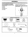
TOOLS REQUIRED
FOR ASSEMBLY
OPERATOR'S
A socket wrench set will make assembly easier. Standard
wrench sizes are listed.
POSITION
(See Fig. 1)
(1) Utility knife
When right or left hand is mentioned in this manual, it
means when you are in the operating pesitior_ (standing
behind tiller handles). -
(1) Wire cutter
FRONT
(1) Screwdriver
(1) Tire pressure gauge
(1) Pair of pliers
(1) 9/16" wrench
LEFT
RIGHT
OPERATOR'S
POSITION
FIG. 1
CONTENTS
OF HARDWARE
PACK
©
W
(1) Handle Lock
(Black)
(1) Handle Lock
(Silver)
(1) Carriage Bolt
3/8-16 UNC x 1 Gr. 5
(1) Center Locknut
3/8-16 UNC
©
(1) Flat Washer 13/32 x I x 11 Ga.
(1) Cable Clip
(1) Handle Lock Lever
(1) Pivot Bolt
3/8-16 UNC Grade 5
(2) Hairpin Clips
5
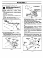
ASSEMBLY
UNPACKING
CARTON
(See Fig. 2)
HANDLE ASSEMBLY
staples when handling or disposing of
CAUTION: material.
Be careful of exposed
cartoning
I &
,..'
/
"UP" POSITION
I
IMPORTANT:
WHEN uNPACKING AND ASSEMBLING
TILLER, BE CAREFUL NOT TO STRETCH OR KINK
CABLES.
•
While holding handle assembly, cut cable ties securing
handle assembly to top frame. Let handle assembly
rest on tiller.
•
Remove top frame of carton.
•
Slowly ease handle assembly up and place on top of
carton.
•
Cut down right hand front and right Rand rear corners
of carton. Lay side qarton wall down.
•
Remove packing material from handle assembly.
TIGHTEN HANDLE
LOCK LEVER TO
HOLD
MOVE
FIG. 4
Rotate handle assembly down. Insert rear carriage
bolt first, with head of bolt on L.H. side of tiller and
loosely assemble Iocknut (See Fig. 5).
SHIFT ROD
Insert pivot bolt in front part of plate and tighten.
Cut down left hand rear corner of carton. Lay roar
carton wall down, which will remove the protective
cardboard flap from leveling shield.
Cut down remaining comers of carton and lay panels
flat.
Lower the handle assembly. Tighten nut on cardage
bolt so handle moves with some resistance. This will
allow for easier adjustment.
HANDLE
ASSEMBLY
Place flat washer on threaded end of handle lock lever.
Insert handle lock lever through handle base and
geamase. Screw in handle lock lever just enough to
hold lever in place.
FIG. 2
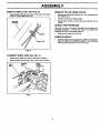
INSTALL
•
•
HANDLE
Insert the smaller silver handle lock (with teeth inward)
in the slot of the handle base (just inside of washer).
(See Figs. 3, 4, and 5)
Insert the thicker black handle lock (with teeth facing to
the dght) in gearcase notch.
Grasphandleassembly. Hold in "up"position. Besure
handle lock remains in gearcase notch. Slide handle
assembly into position.
With handle assembly in lowest position, securely
tighten handle lock lever by rotating clockwise. Leaving handle assembly in lowest position will make it
easier to remove tiller from carton.
VIEWED FROM R.H. SIDE OF TILLER
HANDLE
ASSEMBLY
HANDLE
LOCK
GEARCASE
NOTCH
FLAT
WASHER
SLOT
BLACK
HANDLE
\
HANDLE
LOCK
LEVER
REAR
CARRIAGE
BOLT
//_
FIG. 3
BASE
LOCKNUT
FIG. 5
6
BOLT
PIVOT
ASSEMBLY
INSERT
•
CABLE
CLIP
(See
Fig. 6)
REMOVE TILLER FROM CRATE
Insert plastic cable clip into hole on the back of handle
column. Push cables into clip.
HANDLE
COLUMN
•
Make sure shift lever indicator is in "N" (neutral) position (See Fig. 7)
•
Tilt tiller forward by lifting handle
•
Rotate tiller handle to the right and pull tiller out of
carton.
CHECK TIRE PRESSURE
The tires on your unit were overinflated at the factory for
shipping purposes. Correct and equal tire pressure is
important for best tilling performance.
•
CABLES
Reduce tire pressure to 20 PSI.
HANDLE
• . Handle height may be adjusted to better.suit operator.
(See "TO ADJUST HANDLE HEIGHT" in the Service
and Adjustments section of this manual).
CABLE CLIP
FIG. 6
CONNECT
SHIFT
ROD (See Fig. 7)
•
Insert end of shift into hole of shift lever indicator.
•
Insert hairpin clip through hole of shift rod to secure.
SHIFT
HAIRPIN
CLIP
SHIFT
LEVER
ROD _
HEIGHT
INDICATOR
FIG. 7
7
OPERATION
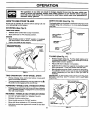
KNOW YOUR TILLER
READ THIS OWNER'S MANUAL AND SAFETY RULES BEFORE OPERATING YOUR TILLER.
Compare the illustrations with your tiller to familiarize yourself with the location of various controls and adjustments. Save
this manual for future reference.
These symbols
meaning.
TILLING
may appear on your TIller or in literature supplied
F
R,&
FORWARD
REVERSE
o
CAUTION
OR WARNING
with the product. Learn and understand their
ENGINE
ON
FUEL
OFF
THROT'rI.E
CONTROL
DRIVE
CONTROL
BAR
SHIFT LEVER
INDICATOR
RECOIL
STARTER
HANDLE
CHOKECONTROL
DEPTH STAKE
LEVELING
SHIELD
OUTER
SIDE
SHIELD
FIG. 8
MEETS ANSI SAFETY
REQUIREMENTS
Our tillers conform to the safety standards of the American National Standards Institute.
SHIFT LEVER - Used to shift transmission gears.
SHIFT LEVER INDICATOR - Shows which gear the
transmission is in.
DRIVE CONTROL BAR - Used to engage tines.
DEPTH STAKE - Controls depth at which tille[ will dig.
LEVELING SHIELD - Levels tilled soil.
RECOIL STARTER HANDLE - Used to start the engine.
CHOKE CONTROL o Used when starting a cold engine.
OUTER SIDE SHIELD - Adjustable to protect small plants
from being buried.
THROTTLE CONTROL - Used to control engine speed.
8
OPERATION
The operation of any tiller can result in foreign objects thrown into the eyes, which can
result in severe eye damage. Always wear safety glasses or eye shields before starting
your tiller and while tilling. We recommend a wide vision safety mask over spectacles or
standard safety glasses.
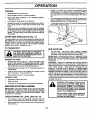
HOW TO USE YOUR TILLER
DEPTH
Know how to operate all controls before adding fuel and
oil or attempting to start engine.
The depth stake can be raised or lows red to allow you more
versatile tilling and cultivating, or to more easily transport
'our tiller.
STOPPING
STAKE
(See Fig. 10).
(See Fig. 9)
TINES AND DRIVE
•
Release drive control bar to stop movement.
•
Move shift lever to "N" (neutral) position.
_TRANSPORT
SHALLOWEST
TILUNG
ENGINE
•
•
j
" POSITION
-
(CULTIVATING)
Move throttle control to "STOP" position. If equipped
with stop switch, move switch to "STOP" position,
DEEPEST _
Never use choke to stop engine.
TILLING
DRIVE CONTROL BAR
"ENGAGED"
POSITION
THROTTLE
OEPTH__.
_
STAKE
SHIFT
LEVER
FIG. 10
TILLING (See Fig. 11)
DRIVE CONTROL BAR
"DISENGAGED"
POSITION
FIG. 9
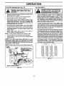
TINE OPERATION
- WITH WHEEL
Always release drive control bar before moving shift
lever into another position.
•
Tins movement is achieved by moving shift leverto (_)
till position and engaging ddve control bar.
FORWARD•
WHEELS
ONLY/TINES
Release depth stake pin. Pull the depth stake up for
increased tilling depth. Place depth stake pin in hole of
depth stake to lock in position.
•
Place shift lever indicator in till position.
•
Hold the drive contro_bar against the handle to start
tilling movement. Tines and wheels will both turn.
•
Move throttle control to "FAST" position for deep tilling.
To cultivate, throttle control can be set at any desired
speed, depending on how fast or slow you wish to
cultivate.
IMPORTANT:
ALWAYS RELEASE DRIVE CONTROL BAR
BEFORE
MOVING
SHIFT
LEVER
INTO ANOTHER
POSITION,
DRIVE
•
•
DEPTH STAKE PIN
"RELEASED"
POSITION
\
STOPPED
Release drive control bar and move shift lever indicator
to "F" (forward) position. Engage drive control bar and
tiller will move forvvard.
REVERSE
- WHEELS
ONLY/TINES
STOPPED
•
DO NOT STAND DIRECTLY BEHIND TILLER.
•
Release the drive control bar.
•
Move throttle control to "SLOW" position.
•
Move shift lever indicator to "R" (reverse) position.
•
Hold drive control bar against the handle to start tiller
movement.
"LOCKED"
POSITION
SIDE SHIELD
9
NUT "A"
FIG. 11
OPERATION
TURNING
•
Engine oil should be to point of overflowing when
engine is level. For approximate capacity see "PRODUCT SPECIFICATIONS" on page 3 of this manual. All
oil must meet A.P.I. Service Classification SF, SG or
SH.
•
For cold weather operation you should change oil for
easier starting (See oilviscosity chart in the Customer
Responsibilities section,of this manual).
To change engine oil, see the Customer Responsibilities section in this manual.
Release the drive control bar.
Move throttle control to "SLOW" position.
Place shift le_,er indicator in "F" (forward) position.
Tines will not turn.
Lift handle to raise tines out of ground.
Swing the handle in the opposite direction you wish to
turn, being careful to keep feet and legs away from
tines.
•
•
When you have completed your turn-around, release
the ddve control bar and lower handle. Place shift lever
in till position and move throttle control to desired
speed. To begin tilling, hold drive control bar against
the handle.
OUTER
SIDE SHIELDS
OIL
LEVEL
(See_Fig. 11)
The back edges of the outer side shields are slottedso that
the shields can be raised for deep tilling and lowered for
shallow tilling to protect small plants from being buded.
Loosen nut "A" in slot and nut "B". Move shield to desired
position (both sides). Retighten nuts.
FILLER
PLUG
PLUG
FiG. 12
TO TRANSPORT
I&
ADD GASOLINE
CAUTION: Before lifting or transporting, allow tiller engine and muffler to
cool. Disconnect spark plug wire. Drain
gasoline from fuel tank.
I
AROUND THE YARD
•
Release the depth stake pin. Move the depth stake
down to the top hole for transporting the tiller. Place
depth stake pin in hole of depth stake to lock in position.
This prevents tines from scuffing the ground.
•
Place shift lever indicator in "F" (forward) position for
transporting.
•
Hold the drive control bar against the handle to start
tiller movement. Tines will not turn.
•
Move throttle control to desired speed.
Disconnect spark plug wire.
Drain fueltank.
•
Transport in upright position to prevent oil leakage.
BEFORE
STARTING
&
ENGINE
IMPORTANT:
BE VERY CAREFUL NOT TO ALLOW DIRT
TO ENTER THE ENGINE W'HEN CHECKING OR '_DDING
OIL OR FUEL. USE CLEAN OIL AND FUEL AND STORE
IN APPROVED,
CLEAN/COVERED
CONTAINERS.
USE
CLEAN FILL FUNNELS.
CHECK
ENGINE
OIL LEVEL
The engine in your unit has been shipped, from the
factory, already filled with SAE 30 summer weight oil.
•
With engine level, clean area around oil filler plug and
remove plug.
CAUTION: Fill to within 112 inch of top
of fuel tank to prevent spills and to
allow for fuel expansion. If gasoline is
accidentally spilled, move machine
away from area of spill. Avoid creating
any source of ignition until gasoline
vapors hav e disappeared.
Do not overfill. Wipe off any spilled oil
or fuel. Do not store, spill or use gasoline near an open flame.
(See Fig. 12)
•
Fill fuel tank. Use fresh, clean, regular unleaded
gasoline. (Use of leaded gasoline will increase carbon
and lead oxide deposits and reduce valve life.)
IMPORTANT= WHEN OPERATING IN TEMPERATURES
BELOW 32°F (0°C), USE FRESH, CLEAN, WINTER GRADE
GASOLINE TO HELP INSURE GOOD COLD WEATHER
STARTING.
WARNING:
Experience indicates that alcohol blended
fuels (called gasohol or using ethanol or methanol) can
attract moisture which leads to separation and formation of
acids during storage. Acidic gas can damage the fuel
system of an engine while in storage. To avoid engine
problems, the fuel system should be emptied before
storage of 30 days or longer. Drain the gas tank, start the
engine and let it run until the fuel lines and carburetor are
empty. Use fresh fuel next season. See Storage section
ofthis manual for additional information. Never use engine
orcarburetor cleaner products in the fuel tank or permanent
damage may occur.
AROUND TOWN
•
•
•
10
OPERATION
TO START
•
•
•
(See Fig. 13)
TILLING
"DISENGAGED"
position when startCAUTION: Keep drive control bar in
ing engine.
A
•
ENGINE
Make sure spark plug Wire is properly connected, and
fuel shut-off valve is open.
Move shift lever indicator to "N" (neutral) position.
Place throttle control in "FAST" position.
Move choke control to full "CHOKE" position. Grasp
recoil starter handle with one hand and grasp tiller
handle with other hand. Pull rope out slowly until
engine reaches start of compression cycle (rope will
pull slightly harder at this point).
•
Pull recoil starter handle quickly. Do not let starter
handle snap back against starter. Repeat if necessary.
•
If engine fires but does not start, move choke control to
half choke position. Pull recoil starter handle until
engine starts.
•
A
Move throttle control to desired running position.
Allow engine to warm up for a few minutes before
engaging tines.
NOTE: If at a high altitude (above 3000 feet) or in cold
temperatures (below 32°F), the carburetor fuel mixture
may need to be adjusted for best engine performance. See
"TO ADJUST CARBURETOR" in the Service and Adjustmerits section of this manual.
NOTE: Ifengine does not start, see troubleshooting points.
CHOKE
CONTROL
\ _
SPARK
PLUG
•
You will find til!ing much easier if you leave a row
untilled between passes. Then go back between tilled
rows. (See Fig. 14) There are two reasons for doing
this. First, wide turns are much easier to negotiate than
about-faces. Second, the tiller won't be pulling itself,
and you, toward the row next to it.
•
Soilconditions are importantfor proper tilling.Tines will
not readily penetrate dry, hard soil which may contribute to excessive bounce and difficult handling of your
tiller. Hard soil should be moistened before tilling;
however, extremely wet soil will "ball-up" or clump
dudng tilling. Wait until the soil is less wet in order to
achieve the best results. When tillingin the fall, remove
vines and long grass to prevent them from wrapping
around the tine shaft and slowing your tillingoperation.
•
Do not lean on handle. This takes weight offthe wheels
and reduces traction. To get through a really tough
section of sod or hard ground, apply upward pressure
on handle or lower the depth stake.
i
FUELSHUT-OFFVALVE
(UNDERNEATH
GASTANK)
TURNSCOUNTERCLOCKOPEN: SEVERAL
WISE
_
TO
I
RECOIL STARTER
HANDLE
FIG. 13
11
{
Tilling is digging into_turning over, and breaking up
packed soil before planting. Loose, unpacked soil
helps root growth. Best tilling depth is 4" to 6". A tiller
will also clear the soil of unwanted vegetation. The
decomposition of this vegetable matter enriches the
soil. Depending on the climate (rainfall and wind), it
may be advisable to tillthe soil at the end of the growing
season to further condition the soil.
NOTE: A warm engine requires less choking to start.
•
handling your tiller, start actual field
use
with throttle
in slow position (midAUTION:
Untilyouareaccustomedto
way between "FAST" and "IDLE").
•
When engine starts, slowly move choke control to
"RUN" position as engine warms up.
•
HINTS
OPERATION
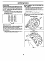
CULTIVATING
ADJUST WHEELS
Figs. 16 and 17)
Cultivating is destroying the weeds between rows to prevent them from robbing nourishment and moisture from the
plants. Atthe same time, breaking up the upper layer of soil
crust willhelp retain moisture in the soil. Best diggingdepth
is 1" to 3". Lower the outer side shields to protect small
plants from being buried.
•
Cultivate up and down the rows at a speed which will
allow tines to uproot weeds and leave the ground in
rough condition, promoting no further growth of weeds
and grass (See Fig. 15).
FOR CULTIVATING
(See
•
Place blocks under right hand side of tiller and remove
hairpin clip and clevis pin from right hand wheel.
•
Move wheel outward approximately 1 inch until hole in
inner wheel hub lines up with inner hole in axle.
•
Replace clevis pin and hairpin clip.on inside of wheel
and remove blocks.
•
Repeat preceding steps on left hand side.
NOTE: In extremely roughconditions and while cultivating,
the wheels should be moved outward on the axle for
increased stability.
=OlOO
OlOO
I
-
_
CLEVIS
3°2
OIO O
TINE
SHEAR
PINS
The tine assemblies on your tiller are secured to the tine
shaft with shear pins (See 'WINE REPLACEMENT" in the
Service and Adjustments section of this manual).
|
_
_
If the tiller is unusually overloaded or jammed, the shear
pins are designed to break before internal damage occurs
to the transmission.
•
)_
_
FIG. 16
If shear pin(s) break, replace only with those shown in
the Repair Parts section of this manual.
INNER VIEW OF TIRE
CLEVIS
PIN
HAIRPIN
FIG. 17
12
"
HAIRPIN
CUSTOMER
RESPONSIBILITIES
MAINTENANCE
SCHEDULE
FILL IN DATES
AS YOU COMPLETE
REGULAR SERVICE
Check Engine Oil Level
sERVICE
v'
DATES
v'
Change Engine Oil
t/
Oil Pivot Points
Inspect Spark Arraster / Muffler
Inspect Air Screen
V'
Ik/
Clean or Replace Air Cleaner Cartridge
I/2
Clean Engine Cylinder Fins
If
Replace Spark Plug
If
1 - Change more often when operating under a heavy load or in high ambient temperatures.
2 - Service more often when operating in dirty or dusty conditions.
GENERAL
RECOMMENDATIONS
LUBRICATION
CHART
The warranty on this tiller does not cover items that have
been subjected to operator abuse or negligence. To
receive full value from the warranty, the operator must
maintain tiller as instructed in this manual,
"THROTrLE
CONTROL
Some adjustments will need to be made periodically to
properly maintain your tiller.
** ENGINE
All adjustments in the Service and Adjustments section of
this manual should be checked at least once each
season.
STAKE
PIN
Once a year you should replace the spark plug, clean
or replace air filter, and check tines and belts for wear.
A new spark plug and clean air filter assure proper airfuel mixture and help your engine run better and last
longer.
BEFORE
EACH
SHIELD
HINGES
USE
•
Check engine oil level.
•
•
Check tine operation.
Check for loose fasteners.
° IDLER
BRACKET
LUBRICATION
WHEEL
HUB
* SAE 30 OR 5W-30 MOTOR OIL
Keep unit well lubricated (See =LUBRICATION CHART"),
** REFER TO CUSTOMER
13
RESPONSIBILITIES
"ENGINE"
SECTION
CUSTOMER
&
RESPONSIBILITIES
Disconnect spark plug wire before performing any maintenance
accidental starting of engine.
AIR FILTER (See Fig. 20)
Your engine will not run properly using a dirty air filter.
Clean the foam pre-cleaner after every 25 hours of operation or every season. Service paper cartridge every 100
hours of operation or eve ry season, whichever occurs first.
Service air cleaner more often under dusty conditions.
•
Loosen air cleaner cover screws. Remove cover and
air cleaner assembly from base.
•
Remove air cleaner assembly from inside cover and
disassemble.
TO SERVICE PRE-CLEANER
•
Wash it in liquid detergent and water.
•
Squeeze it dry in a clean cloth.
•
Saturate it in engine oil. Wrap it in clean, absorbent
cloth and squeeze to remove excess oil.
TO SERVICE CARTRIDGE
•
Gently tap the flat side of the paper cartridge to dislodge dirt. Do not wash the paper cartridge or use
pressurized air, as this will damage the cartridge.
Replace a dirty, bent, or damaged cartridge.
•
Reassemble retainer on pre-cleaner and cartridge
(screen side of pre-cleaner toward cartridge pleats).
Place assembly into cover.
•
Insert tabs on cover into slots in base and tighten cover
screws securely.
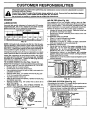
LUBRICATION
Use only high quality detergent oil rated with API service
classification SF, SG or SH. Select the oil s SAE viscosity
grade according to your expected temperature.
SAE VISCOSITY GRADES
-20 _
O°
-20 °
TEMPERATURE
30"
-10 °
32 °
40"
O°
RANGE ANTICIPATED
10"
20"
30"
BEFORE NEXT OIL CHANGE
FIG. 18
NOTE: Although multi-viscosity oils (5W-30, 10W-30, etc.)
improve starting in cold weather, these multi-viscosityoils
will result in increased oil consumption when used above
32°F (0°C). Check your engine oil level more frequently to
avoid possible engine damage from running low on oil,
Change the oil after every 50 hours of operation or at least
once a year if the tiller is not used for 50 hours in one year.
Check the crankcase oil level before starting the engine
and after each five (5) hours of continuous use. Add SAE
30 motor oil or equivalent. Tighten oil filler plug securely
each time you check the oil level.
"BASE
TO CHANGE ENGINE OIL (See Figs. 18 and 19)
Determine temperature range expected before oil change.
All oil must meet API service classification SF, SG or SH.
•
Be sure tiller is on level surface.
•
Oil will drain more freely when war m.
•
Use a funnel to prevent oil spill on tiller, and catch oil in
a suitable container.
•
•
•
•
•
to prevent
Preventfires!
Keep the englne free of grass, leaves, apilledoil, orfuel. Remove fuel from tank before tipping
unit for maintenance. Clean muffler area of all grass, dirt, and debris.
Do not touch hot muffler or cylinder fine as contact may cause burns.
ENGINE
-30 °
(except carburetor adjustment)
RETAINER
-SLOT i
Remove drain plug, For easier removal of plug use
7/16 12 pt socket with extension.
Tip tiller forward to drain oil.
After oil has drained completely, replace oil drain plug
and tighten securely.
Remove oil filler plug. Be careful not to allow dirt to
enter the engine.
Refill engine with oil. See "CHECK ENGINE OIL
LEVEL" in the Operation section of this manual.
COVER SCREWS
DUAL ELEMENT/CARTRIDGE AIR CLEANER
FIG. 20
COOLING
SYSTEM
(See Fig. 21)
Your engine is air cooled. For proper engine performance
and long life keep your engine clean.
•
Clean air screen frequently using a stiff-bristled brush.
•
Remove blower housing and clean as necessary.
Keep cylinder fins free of dirt and chaff.
.CYUNDER
OIL
DRAIN
FINS
PLUG_
AIR SCREEN
OIL LEVEL
PLUG
FIG. 21
FIG. 19
14
CUSTOMER
RESPONSIBILITIES
MUFFLER
TRANSMISSION
Do not operate tiller without muffler. Do not tamper with
exhaust system. Damaged mufflers or spark arresters
could create a fire hazard. Inspect periodically and replace
if necessary. If your engine is equipped with a spark
attester screen assembly, remove every 50 hours for
cleaning and inspection. Replace if damaged.
Your trensmission issealed and willonly require lubrication
if serviced.
•
Clean engine, wheels_ finish, etc. of all foreign matter.
SPARK
•
Keep finished surfaces and wheels free of all gasoline,
oil, etc.
•
Protect painted surfaces with automotive type wax.
CLEANING
PLUG
Replace spark plugs at the beginning of each tillingseason
or after every 50 hours of use, whichever comes first. Spark
plug type and gap setting is shown in "PRODUCT SPECIFICATIONS" on page 3 of this manual.
SERVICE
I
A_,
We do not recommend using a garden hose to clean your
unit unless the muffler, air filter and carburetor are covered
to keep water out. Water in engine can result in a shortened
engine life.
AND ADJUSTMENTS
contact
withDisconnect
plug.
CAUTION:
spark plug wire from spark plug and place wire where it cannot come into
TILLER
TO REMOVE
WHEEL
(See Fig. 23)
•
Place blocks under transmission to keep tiller from
tipping.
Select handle height best suited for your tilling conditions.
Handle height will be different when tiller digs into soil.
•
First loosen handle lock lever.
•
Remove outer side shield by removing nuts"A" and"B".
•
Remove inner side shield by removing nuts "C" and
•
Handle can be positioned at different settings between
"HIGH" and "LOW" positions.
•
•
Remove hairpin clip and clevis pin from wheel.
Remove wheel and tire.
•
Retighten handle lock lever securely after adjusting.
•
Repair tire and reassemble.
TO ADJUST
HANDLE
HEIGHT
(See
Fig.
22)
""-': _,', _;!_ ,,, /POSITION)
CLEVIS
":'-:_ ',._
'_.;_;_*'."._:.
': "t,.
", '*,%,
.AHDL
',".
HANDLE (H HANDLE
GH
LOCK
/ LEVER
*%
',
POS,,,ON
%%,
:;
HAIRPIN
CLIP
FIG. 22
TIRE CARE
• NUT'"B"
SIDE
SHIELD
less beads are seated, overinflation
CAUTION:
When
mounting tires, uncan
cause an
explosion,
f_
I
Maintain 20 pounds of tire pressure. If tire pressures
are not equal, tiller will pull to one side.
Keep tires free of gasoline or oil which can damage
rubber.
15
NUT "A"
FIG. 23
SIDE
SHIELD
SERVICE
TO REMOVE
•
BELT GUARD
AND ADJUSTMENTS
TO REPLACE
(See Fig. 24)
GROUND
DRIVE BELT (See
Figs. 24 and 25)
Remove hairpinclipandclevis pin fromleftwheel. Pull
wheel out from tiller about I inch.
•
Remove cap nut and washer, and hex bolt and washer
from side of belt guard.
Removebeltguard. (See"TOREMOVEBELTGUARD"
in this section of this manual).
•
Loosen belt guides "A" and "S".
•
Remove hex nut and washer from bottom of belt guard
(located behind wheel).
•
•
•
Pull belt guard out and away from tiller.
•
Replace belt guard by reversing above procedure.
Remove old belt by s!ipping from engine pulley first.
Place new belt in groove of transmission pulley and
into engine pulley. BELT MUST BE IN GROOVE ON
TOP OF IDLER PULLEY. NOTE POSITION OF BELT
TO GUIDES.
•
Tighten belt guides "A" and "B".
•
Check belt adjustment as described below.
•
Replace belt guard.
•
CAP NUT AND
WASHER
BELT GUARD
PIEX NUT
WASHER
(LOCATED
BEHIND
....
Reposition wheel and replace clevis pin and hairpin
clip.
GROUND
Fig. 25)
DRIVE
BELT
ADJUSTMENT
(See
For proper belt tension, the extension spring should have
about 518 inch stretch when drive control bar is in "ENGAGED" position. This tension can be attained as follows:
HEX BOLT
AND WASHER
HAIRPIN CLiP AND CLEVIS PIN
FIG. 24
•
Loosen cable clip screw securing the drive control
cable.
•
Slide cable forward for less tension and rearward for
more tension until about 5/8 inch stretch is obtained
while the drive control bar is engaged.
•
Tighten cable clip screw securely.
BELT
CABLE CLIP
ENGINE
PULLEY
IDLER
PULLEY
SPRING
' TRANSMISSION
PULLEY
FIG. 25
16
SERVICE AND ADJUSTMENTS
TINE REPLACEMENT
(See Figs, 26, 27 and 28)
I &
To maintain the superb tilling performance of this
machine the tines should be checked for sharpness,
wear, and bending, particularly the tines which are next
to the transmission.
If the gap between the tines
exceeds 3-1/2 inches they should be replaced or
straightened as necessary.
gloves or other protection when hanCAUTION:
dling
tines. Tines are sharp.
Wear
New tines should be assembled as shown in Fig. 28.
Sharpened tine edges will rotate rearward from above.
A badly worn tins causes your tiller to work harder and dig
more shallow. Most important, worn tines cannot chop and
shred organic matter as effectively nor bury it as deeply as
ood tines. A tins this worn needs to be replaced.
NEW TINE
TINE
TRANSMISSION
--Lw,
I I
III-
WORN TINE
3-1/2
FIG. 26
FIG. 27
SHARP EDGES
_I
TINE
OUNTER
ROTATION
HAIRPIN
CLIP
HAIRPIN CLIP
SHARP EDGE
CLEVIS PIN
SHARP EDGE
SHARP
EDGE
SHARP
EDGES
FIG. 28
17
SERVICE AND ADJUSTMENTS
ENGINE
TO ADJUST
Maintenance, repair, or replacement of the emission control devices and systems, which are being done at the
customers expense, may be performed by any non-road
engine repair establishment or individual. Warranty repairs
mustbe performed by an authorized engine manufacturer's
service outlet.
The carburetor has a high speed jet and has been preset at
the factory and adjustment should not be necessary. However, minor adjustments may be required to compensate
for differences in fuel, temperature, altitude or load. If the
carburetor does need adjustment, proceed as follows.
TO
•
ADJUST
(See
THRO'B'LE
CONTROL
CABLE
Loosen cable clamp screw to allow cable to move.
•
Move throttle control lever on upper handle to "FAST"
position.
Pull throttle cable out to end of travel
•
•
(See
Fig. 30)
IDLE RPM ADJUSTMENT
Fig. 29)
•
CARBURETOR
TO adjust idle RPM, rotate throttle linkage counterclockwise and hold against stop while adjusting idle
speed adjusting screw to obtain 1750 RPM. Re.lease
throttle linkage.
ACCELERATION
•
Hold cable in this position and tighten clamp screw
securely.
TEST
Move throttle control lever from "SLOW" to "FAST"
position. If engine hesitates or dies, turn needle valve
out (counterclockwise) 1/8 turn. Repeat test and
continue to adjust, if necessary, until engine accelerates smoothly.
High speed stop is factory adjusted. Do not adjust or
damage may result.
IMPORTANT:
NEVER TAMPER WITH THE ENGINE
GOVERNOR, WHICH IS FACTORY SET FOR PROPER
ENGINE SPEED. OVERSPEEDING THE ENGINE ABOVE
THE FACTORY HIGH SPEED SETTING
CAN BE
DANGEROUS. IF YOU THINKTHE ENGINE-GOVERNED
HIGH SPEED NEEDS ADJUSTING, CONTACT YOUR
NEAREST
AUTHORIZED
SERVICE
CENTER/
DEPARTMENT, WHICH HAS THE PROPER EQUIPMENT
AND EXPERIENCE
TO MAKE ANY NECESSARY
ADJUSTMENTS.
CLAMP
SCREW
THROTTLE"
LINKAGE
THROTTLE
CABLE
FIG. 29
IDLE NEEDLE
VALVE
IDLE SPEED
ADJUSTING
SCREW
FIG. 30
18
STORAGE
ENGINE
Immediately prepare your tiller for storage at the end of the
season or if the unit will not be used for 30 days or more.
CAUTION:
OIL
Drain oil (with engine warm) and replace with clean oil.
(See "ENGINE" in the Customer Responsibilities section of
this manual).
Never store the tiller with
where
fumes
may
reach
an open
flame
gasoline
in the
tank
inside
a building
or spark. Allow the engine to cool
before storing in any enclosure.
CYLINDER(S)
TILLER
•
Remove spark plug.
•
Pour 1 ounce (29 ml) of oil through spark plug hole into
cylinder.
•
Pull starter handle slowly several times to distribute oil.
•
Clean entire tiller (See "CLEANING" in the Customer
Responsibilities section of this manual).
•
Replace with new spark plug.
•
Inspect and replace belts, if necessary (See belt replacement instructions in.the Service and Adjustments
section of this manual).
OTHER
•
Do not store gasoline from one season to another.
•
Lubricate as shown in the Customer Responsibilities
section of this manual.
•
Replace your gasoline can if your can starts to rust.
Rust and/or dirt in your gasoline will cause problems.
•
Be sure that all nuts, bolts and screws are securely
fastened. Inspect moving parts for damage, breakage
and wear. Replace if necessary.
•
If possible, store your unit indoors and cover it to give
protection from dust and dirt.
•
Touch up all rusted or chipped paint surfaces; sand
lightly before painting.
•
Cover your unit with a suitable protective cover that
does not retain moisture. Do not use plastic. Plastic
cannot breathe which allows condensation to form and
will cause your unit to rust.
IMPORTANT:
NEVER COVER TILLER WHILE ENGINE
. AND EXHAUST AREAS ARE STILL WARM.
ENGINE
FUEL SYSTEM
IMPORTANT:
IT IS IMPORTANT
TO PREVENT
GUM
DEPOSITS
FROM
FORMING
IN ESSENTIAL
FUEL
SYSTEM
PARTS SUCH AS THE CARBURETOR,
FUEL
FILTER, FUEL HOSE, OR TANK DURING
STORAGE.
ALSO,
EXPERIENCE
INDICATES
THAT ALCOHOL
BLENDED
FUELS
(CALLED
GASOHOL
OR USING
ETHANOL OR METHANOL)
CAN ATTRACT MOISTURE
WHICH LEADS TO SEPARATION
AND FORMATION
OF
ACIDS DURING STORAGE.
ACIDIC GAS CAN DAMAGE
THE FUEL SYSTEM OF AN ENGINE WHILE IN STORAGE.
•
Drain the fuel tank.
•
Start the engine and let it run until the fuel lines and
carburetor are empty.
•
Never use engine or carburetor cleaner products in the
fuel tank or permanent damage may occur.
Use fresh fuel next season.
•
NOTE: Fuel stabilizer is an acceptable alternative in
minimizing the formation of fuel gum deposits during storage. Add stabilizer to gasoline in fuel tank or storage
container. Always follow the mix ratio found on stabilizer
container. Run engine at least 10 minutes after adding
stabilizer to allow the stabilizer to reach the carburetor. Do
not drain the gas tank and carburetor if using fuel stabilizer.
19
TROUBLESHOOTING
PROBLEM
CAUSE
Will not start
1.
Out of fuel.
2.
3.
4.
5.
Engine not "CHOKED" properly.
Engine flooded,
Dirty air cleaner.
Water in fuel.
6.
7,
8.
9.
10.
Clogged fuel tank.
Loose spark plug wire.
Bad spark plug or improper gap.
Carburetor out of adjustment.
Oil soaked air filter.
Hard to start
1.
2.
3,
4.
5,
6.
Thmtlle control not set pmpedy,
Dirty air cleaner.
Bad spark plug or improper gap.
Stale or dirty fuel.
Loose spark plug wire.
Carburetor out of adjustment.
Loss of power
1.
2.
3.
4.
5.
Engine is overloaded.
Dirty air cleaner.
Low oil level/dirty oil.
Faulty spark plug.
Oil in fuel.
6,
7.
Stale or dirty fuel.
Water in fuel.
8.
9.
10.
11.
12.
13.
Engine overheats
Low oil level/dirty oil.
Dirty engine air screen.
Dirty engine.
Partially plugged muffler.
improper carburetor adjustment.
1.
Soil balls up or clumps
Engine runs but
won't move
tiller
Engine runs but
when tilling
labors
Excessive
bounce/
CORRECTION
1.
2.
3.
4.
5.
Fillfuaitank.
See "TO START ENGINE" in OperaUonsection.
Wait severalminutesbeforeattemptingto start.
Clean or replaceair cleanercartridge.
Drainfuel tankand carburetor,and refilltankwith fresh
gasoline.
6. Removefuel tankand clean.
7. Make sure sparkplugwire is seatedproperly on plug.
8. Replacesparkplugor adjustgap.
9. Make necessaryadjustments.
10. Replaceair filter.
1,
2,
3.
4.
5.
6.
Place throttle control in "FAST" position.
Clean or replace air cleaner cartridge.
Replace spark plug or adjust gap,
Drain fuel tank and refill with fresh gasoline.
Make sure spark plug wire is seated property on plug.
Make necessary adjustments.
2.
3.
4.
5.
6.
7.
Cloggedfueltank.
Sparkplug wire louse.
Dirtyengineair screen.
Dirty/cloggedmuffler.
Carburetoroutof adjustment.
Poorcompression.
1.
2.
3.
4.
5.
POINTS
8.
9.
10.
11.
12.
13.
1.
2,
3.
4,
Check oil levet/change oil.
Clean engine air screen.
Ctsan cylinder fins, air screen, and muffler area,
Remove and clean muffler,
5.
Adjust carburetor to richer position.
Ground too dry and hard.
1.
Moisten ground or wait for more favorable soil
conditions.
1.
Ground too wet.
1.
Wait for more favorable
1.
2.
3.
Drive control bar is not engaged.
V-belt not correctly adjusted.
V-belt is off pulley(s).
1.
2.
3.
Engage drive control.
Inspect/adjustV-bait.
Inspect V-belt.
Tilling too deep.
difficult handling
Tines will not rotate
Set depth stakefor shallowerUiting.
Clean or replaceair cleanercartridge.
Check oil level/change oil.
Clean andregap or changespark plug.
Drainandclean fueltank and refill,and cleancarburetor.
Drainfueltank and refillwith fresh gasoline.
Drain fuel tank andcarburetor,and refilltankwith fresh
gasoline.
Remove fuel tank and clean.
Connectand tighten sparkplug wire.
Clean engine air screen.
Clean/replacemuffler.
Make necessaryadjustments.
Contactan authorizedservicecanter/department.
"1,
soil conditions.
2.
3.
Throttle control not properly adjusted.
Carburetor out of adjustment,
1.
2.
3.
Set depthstake forshallowertilling.
Checkthrottlecontrolsetting.
Make necessaryadjustments.
1.
Shear pin(s) broken.
t.
Redtace shearpin(s).
20
REPAIR PARTS
TILLER - - MODEL NUMBER
944.627592
HANDLES
/
2
2
•
28' ',
s .._.__/
1
\'\
15
\
23
11
\
\
\
KEY
NO.
1
2
3
4
5
6
7
8
9
10
11
12
13
14
15
16
17
18
PART
NO.
138305
141406
110673X
127254X
6712J
137119
110641X
71191008
72010520
110646X
4497H
81328
138295
109313X
110702
72140608
109229X
73930600
KEY
NO.
DESCRIPTION
Throttle, Control
Grip, Handle
Grommet, Handle
Bar, Assembly Control
Cap, Vinyl
Panel, Control
Bushing, Split
* Screw 10-24
* Bolt, 5116-18 x 2.50
Handle, Grip
Retainer, Spring
Bolt, Shoulder
Handle, Shift
C-_ommet, Rubber
Rod, Shift
* Bolt, Carriage 3/8-16 x 1
Lock, Handle
* Nut, Centerlock 3/8-16
19
20
21
22
23
24
25
26
27
28
29
30
. 31
PART
NO.
19131611
109228X
150628
165197
86777
9484R
73970500
138306
73220400
10040400
73731000
138283
150696
\
\'\.
\
31
DESCRIPTION
Washer 13/32xl xll Ga.
Lever, Lock, Handle
Column, Handle, Asm.
Clip, Plastic, Cable
,, •
Screw, Hex, Washer #10-24 x 1/2
Clip
Locknut, Hex, Flange
Clutch, Cable
* Nut, Fin, Hex 1/4-20
* Washer, Lock Hvy Helical 1/4
Nut, Keps #10-24
Lock, Handle
Bolt, Pivot
• STANDARD HARDWARE - - PURCHASE
LOCALLYAssembly
NOTE:
21
All component dimensions
1 inch = 25.4 mm
given in U.S. inches.
REPAIR PARTS
TILLER - - MODEL NUMBER
MAINFRAME,
944.627592
LEFT SIDE
3
9
35
11
17
15
15 22
27
26
23
KEY
NO.
PART
NO.
1
2
3
4
5
6
7
8
9
106160X
10040600
73220600
74930572
154734
110111X
72110404
8700J
86777
10
11
12
13
14
15
16
17
18
19
20
21
22
23
9484R
10040400
73220400
23230506
8382J
19111116
145102
73220500
8381J
12000028
4914H
139155
104214X
5015J
138417
795R
4929H
24
33
DESCRIPTION
24
O-Ring
Washer, Lock 3/8
Nut, Hex 3/8-16
Bolt, Hex Head 5/16-18 x 4-1/2
Screw Shift Lever
Lever, Shift
Bolt, Carriage 1/4-20 x 112 Grade 5
Plate, Shift Indicator
Screw, Hax Washer Head, Slotted
#10-24 x 1/2
Clip
Washer, Lock 1/4
Nut, Hex 1/4-20
Screw, Set, Hex 5/16-18 x 3/8
Spacer, Split 0.327 x 0.42 x 2.68
Washer 11/32 x 11/16 x 16 Gauge
Sheave, Transmission
Nut, Hex 5/16-18
Spacer
.
Ring, Retainer
Key, Square
Spacer, Split .523 x .718 x 2
Nut, Cap 5/16-18
Tire
Rim
Tire Valve
Rivet, Drilled
25
KEY
NO.
PART
NO.
25
26
27
28
29
30
31
32
33
34
35
36
4921H
102818X558
138399
104679X
12000032
159229
74770844
139401
19171616
4368J
140062
69180
NOTE:
22
DESCRIPTION
Clip, Hairpin
Guard, Belt
V-Belt
Pulley, Idler
Ring, Klip
Bracket, Idler
Bolt, Hex Head 1/2-20 x 2-3/4
Shaft, IdlerArm
Washer
Sheave, Engine
Cap, Plunger
Nut Lock #10-24
All component dimensions given in U.S. inches.
1 inch = 25.4 mm
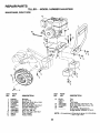
REPAIR PARTS
TILLER - - MODEL NUMBER 944.627592
MAINFRAME,
RIGHT SIDE
17
\
8 9
8
9
7
KEY
NO.
PART
NO.
1
2
4
5
8
7
8
9
10
11
12
138402
73510500
74760528
138669
74760616
8450J
10040600
73220600
72140608
4921H
4929H
KEY
NO.
DESCRIPTION
13
Bumper
Nut 5/16-18
Bolt, Hex 5/16.;18 x 1-3/4:
Bracket, Engine
Bolt, Hex Heed 3/8-16 x 1
Counter Weight, R.H.
Washer, Lock 3/8
Nut, Hex 3/8-16
Bolt, Carriage 3/8-16 x 1
Clip, Hairpin
Rivet, Drilled
14
15
16
17
PART
NO.
5015J
138417
795R
72470636
74760672
7192J
.......
DESCRIPTION
Tire
Rim
Tife Valve
Bolt, Carriage 3/8-16 x 4-1/2
Bolt, Hex Head 3/8-16 x 4-1/2
Tie, Cable
Engine (See Breakdown)
Briggs Model 19G402-1170-E1
NOTE: All component dimensions given in U.S.inches.
1 inch = 25.4 mm
23
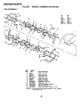
REPAIR PARTS
TILLER
- - MODEL NUMBER
944.627592
TRANSMISSION
8
3
7
4
lO
5
25
41
21
22
44
17 24
41
36
"
37
35
41
38
49
KEY
NO.
PART
NO.
1
162169
162163
2
3
4
5
6
7
8370J
8547J
8546J
100413K
674A291
674A290
8
9
10
11
12
13
14
15
16
17
18
19
21
22
23
24
25
4358J
8358J
8371J
100371K
7392M
8353J
8354J
12000039
154467
1370H
4895H
150695
105378X
106181X
8359J
5020J
164396
8
41
KEY
NO.
DESCRIP_ON
Transmission Assembly
Gearcase Assembly, R.H.,
with Beadng (Includes Key No. 18)
Bolt, Upset
Gear, Reverse
Gear, Cluster, Red., 1st and 2nd
Bear!ng, Needle
Sprocket Assembly, Tine
Sprocket Assembly with Bearings
(Includes Key #6 & two of Key #5)
Washer
Shaft, Reduction, 1st
Chain, Roller, 60P
Spring, Shift, Fork
Ball, Steel
Fork, Shift
Shaft, Shift
Klip Ring
Washer, Seal
Race, Bearing, Thrust, 5/8 I.D.
searing, Needle
Shaft, Input
Shaft Assembly, Tine
Spacer 1.008 x 1-3/4 x .645
Pinion, Input
Bearing, Needle
Gasket, Gearcase
PART
NO.
26
27
28
29
106389X
100433M
8357J
674A289
30
31
32
33
34
35
36
37
38
41
42
43
44
6803J
12000040
8356J
100016K
106392X
106394X
100436L
142145
106393X
155236
10040700
73610700
162165
45
47
48
49
--
17720510
73220500
100107K
106391X
6066J
NOTE:
24
DESCRIPTION
Spacer .765 I.D. x 1.12 x 5/8
Gear, Cluster, Red., 2nd and 3rd
Gear, Reverse Idler
Gear Assembly, Reverse Idler
(Includes Key Numbers 28 and 30)
Bearing, Needle
Klip Ring
Shaft, Reverse Idler
Shaft, Reduction, 2nd
Spacer .765 I.D. x 1-1/8 x 1-3/8
Spacer, Ground Drive, L.H.
Shaft Assembly, Ground
Arm Assembly, Shift
Spacer, Ground Drive, R.H.
Seal, Oil
Washer, Lock 7/16
Nut, Hex 7/16-20
Gearoase Assembly, L.H., with
Bearing (Includes Key Number 24)
Screw 5/16-18 x 5/8
Nut, Hex Head 5/16-18
Screw, Whiz-Lock 5/16-18 x 4
Spacer .765 I.D. x 1.12 x 3/4
Grease, Plastilub Number 1
All component dimensions given in U.S.' inches
1 inch = 25.4 mm
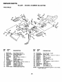
REPAIR PARTS
TILLER - - MODEL NUMBER
944.627592
TINE SHIELD
8
10
8
9
28
24
24
15
13
19
21
KEY
NO.
1
2
3
4
5
6
7
8
9
10
11
12
13
14
15
PART
NO.
98000129
161416X558
8393J
12000036
72140508
8394J
8392J
109230X
104178X558
72140506
73220500
10040500
10040400
8386J
161417X558
KEY
NO.
DESCRIPTION
Nut, Flange 5/16-18
Shield, Side, Outer, L.H.
Pin, Depth Stake
Ring, Klip
Bolt, Carriage 5/16-18 x 1
Spring
Bracket, Latch
Spring, Depth Stake
Shield, Tine
Bolt, Carriage 5/16-18 x 3/4 Gr.
Nut, Hex 5/16-18
Washer, Lock 5/16
Washer, Lock 1/4
Bracket, Shield Tine
Shield, Side, Outer R.H.
16
17
18
19
20
21
22
23
24
25
26
27
28
29
PART
NO.
73220400
104084X558
72040410
102701X
73220600
138420
74930632
4440J
72140408
6712J
109227X
102713X558
138609
162175
NOTE:
25
DESCRIPTION
Nut, Fin, Hex 1/4-20
Shield, Side
Bolt, Carriage 1/4-20 x 1-1/4 Gr. 5
Grip
Nut, Hex 3/8-16
Stake, Depth
Bolt, Hex 3/8-16 x 2
Hinge
Bolt, Carriage 1/4-20 x 1/2 Gr. 5
,Jap, Vinyl
Pad, Idler
Shield, Leveling
Pin, Hinge
Nut, Wing 5/16-18
All component dimensions given in U.S. inches.
1 inch = 25.4 mm
REPAIR PARTS
TILLER - - MODEL NUMBER
944,627592
TINE ASSEMBLY
A
A
B
_7
_10
_"_7
_10
A
3
7
7
1
2
2
A
6
4
7
7
3
KEY
NO.
1
2
3
4
5
6
7
8
9
10
11
PART
NO.
6556J
100445L
6557J
101194M
4929H
163552
10040600
101193M
74610616
73610600
74610624
NOTE:
4
DESCRIPTION
Tine, L.H., 14"
Hub Assembly
Tine, R.H., 14"
Tine, LH., 14"
Rivet, Panhead
Retainer Spring
Washer Lock 3/8
Tine, R.H., 14"
Bolt, Hex Head 3/8-24 x 1
Nut, Hex 3/8-24
Bolt, Hex Head 3/8-24 x 1-1/2
All component dimensions given in U.S. inches.
1 inch = 25.4 mm
26
REPAIR PARTS
TILLER - - MODEL NUMBER
944.627592
DECALS
2
8
9
6
5
12
7
11
KEY
NO.
PART
NO.
1 158097
2 157986
3 157987
4 138813
5 110614X
6 138546
7 12-0076X
8 110612X
9 165270
10 137282
11 "157988
12 168260
13 162384
-168560
-168561
DESCRIPTION
Decal, Logo
Decal, Logo
Decal, Logo
Decal, Craftsman
Decal, Hand Placement
Decal, Shift Indicator
Decal, Warning, Rotaing Tines
Decal, Caution
Decal, Briggs & Stra_tton
Decal, Instr.
Decal, Cou. Rot. Tines
Decal, Tine, Depth Stake
Decal, Warning, Till Eng/Fr
Manual, Owner's (English)
Manual, Owner's (French)
27
REPAIR PARTS
TILLER - - MODEL NUMBER
ENGINE, BRIGGS
& STRATI'ON
944.627592
- - MODEL NUMBER
19G402, TYPE NO. 1170._E1
296
'14
300
12
307_
13 _
3o8
$
13A
7
8
10
11036 LABEL
KIT_
GASKET
SET]
it" REQUIRES SPECIAL TOOLS TO INSTALL.
SEE REPAIRINSTRUCTION
MANUAL.
28
REPAIR PARTS
TILLER - - MODEL NUMBER
ENGINE,
BRIGGS & STRATTON
944.627592
- - MODEL NUMBER
19G402, TYPE NO. 1170-E1
REQUIRES SPECIAL TOOLS
TO INSTALL; SEE REPAIR
INSTRUCTION MANUAL.
29
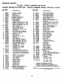
REPAIR PARTS
TILLER - - MODEL NUMBER 944.627592
ENGINE, BRIGGS
KEY PART
NO. NO.
1
2
3
5
7
8
9
10
11
12
13
13A
14
15
16
18
19
20
21
22
23
24
25
26
495631
495657
391086
214347
272163
498038
27803
94621
280819
271701
27876
27877
94565
94926
93723
94880
94239
495648
94388
496982
295964
391086
281658
93585
298260
222698
499907
499908
499909
499910
499921
690018
690019
690020
27
28
29
263181
499911
499920
390401
390773
& STRA'n'ON
- - MODEL NUMBER
DESCRIPTION
Cylinder Assembly
Bushing, Cylinder
"Seal, Oil
Head, Cylinder
_* Gasket, Cylinder Head
Breather Assembly
_* Gasket, Breather
Screw, Sems
Tube, Breather
* Gasket, Crankcase Cover 1/64"
* Gasket, Crankcase Cover .005"
* Gasket, Crankcase Cover .009"
Screw, Cylinder Head 3-9/16"
Stud, Hex, Ddve
Screw, Cylinder Head 3"
Plug, Oil Drain, Flush
Plug, Oi_ Drain, Square Head
Crankshaft
Key, Timing Gear Retaining
Cover Assembly, Crankcase
Bushing, Crankcase
* Seal, Oil
Plug, Oil Filler
Screw, Crankcase Cover
Flywheel
Key, Flywheel
Piston Assembly standard
Piston Assembly, .010" O.S.
Piston Assembly, .020" O.S.
Piston Assembly, .030" O.S.
Ring Set, Piston Standard
Ring Set, Piston, 0,010"
Oversized
Ring Set, Piston, 0,020"
Ring Set, Piston, 0,030"
Oversized
Lock, Piston Pin
Pin Assembly, Piston Standard
Pin Assembly, Piston 005" 03.
Rod Assembly, Connecting (Std.)
Rod Assembly, Connecting (.020"
KEY PART
NO. NO.
222113
92659
263017
261055
65906
222475
94811
221596
260933
214786
214170
272708
272707
94778
393576
DESCRIPTION
56
57
58
59
60
63
64
65
295871
490179
88884
490653
490652
260414
281204
94904
66
67
68
70
71
73
74
75
75A
93
94
95
98
98A
104
105
106
108
116
121
123
125
127
399671
394897
63770
298799
394506
224874
94680
225136
495659
281346
496589
94098
495800
493280
231789
231935
231856
224666
280203
497581
94913
690011
130
131
133
137
138
141
142
224539
498846
494381
281165
281164
497160
690125
690126
161 497669
163 273101
165 94692
186 230318
186A493496
u. s.)
30
32
33
34
35
37
38
40
45
46
50
51
51A
53
55
19G402, TYPE NO. 1170-E1
Dipper Connecting Rod
Screw, Connect ng Rod
Valve, Exhaust
Valve, Intake
Spring, Valve
Guard, Flywheel
Screw, Sems
Retainer valve
Tappet, Valve
Gear, Cam
Elbow, Intake
_.• Gasket, Carburetor Mounting
A• Gasket, Intake Manifold
Stud, Carb. Mounting
Housing, Rewind Starter
RPM Settings:
i_
included
Included
Included
included
NOTE:
3O
Pulley, Rewind Starter
Spring, Rewind Starter
Rope, Rewind Starter
Insei't, Starter Handle
Handle, Rewind Starter
Spring, Ratchet
Adapter, Ratchet Spring.
Screw, Rewind StarterHousing
Mounting
Clutch Assembly, Rewind Starter
Housing, Rewind Starter Clutch
Ball, Clutch
Ratchet, Rewind Starter Clutch
Washer, Clutch Retaining
"
Screen, Rewind Starter
Screw, Sems
Washer, Spring
Washer, Set
• Bushing, Throttle Shaft
Valve, td_eAdjustment
• Screw, Slotted
Screw, Idle Speed
Screw, Idle Speed
• Pin. Float Hinge
• Valve, Needle
• Seat, Inlet
Valve, Choke
O-Ring, Fuel Valve
Carburetor Overhaul Kit
Screw Ton<.
Carburetor
• Plug, Welch
(Sold in Kit Only)
Valve, Throttle
Shaft, Throttle
Float, Carburetor
A. Gasket, Float Bowl
A, Washer
Shast, Choke
Nozzle, Carburetor (Standard)
Nozzle, Carburetor (High Altitude
Base, Air Cleaner
a* Gasket, Air Cleaner
Nutwing
Connector, Hose
Connector, Hose
Low: 1750 - 1950
High: 3500 - 3700
in Gasket Set (497070)
in Carburetor Kit (497578)
in Carburetor Gasket Set (497069)
in Valve Overhaul Gasket Set (497534)
All component dimensions given in U.S. inches
1 inch = 25.4 mm
REPAIR PARTS
TILLER - - MODEL NUMBER 944.627592
ENGINE, BRIGGS
& STRATTON
- - MODEL NUMBER
KEY PART
NO. NO.
DESCRIPTION
187 296004
187A 497029
188 94627
200 221760
201 263051
202 263049
203 497207
209 263212
210 492044
211 263182
219 497037
220 221551
222 499103
227 499096
230 94927
232 263020
258 94929
265 221535
298 261409
300 496127
304 491596
305 94786
306 496797
307 94930
308 225055
332 92284
333 398811
334 94731
337 496018
346 94896
353 92791
354 94726
354A90576
356 398838
356A 496868
358 497070
363 19203
373 94908
383 89838
385 94789
387 496257
445 496077
467 280715
520 93722
552 491893
562 94907
592 231978
Line, Fuel
Line, Fuel
Screw, Hex
Guide, Air
Link, Governor
Link, Throttle
Lever, Linkage
Spring, Governor
Strainer, Fuel
Spdng, Governedldle
Gear Governor
Washer, Thrust
Plate, Governor Control
Lever Assembly, Governor
Washer, Governor Crank
Spring, Link
Screw, Sems
Clamp, Casing
Locknut, Muffler
Muffler, Exhaust
Housing, Blower
Screw, Sems
Shield, Cylinder
Screw, Cylinder Shield
Cover, Cylinder Head
Nut, Flywheel
Armature, Magneto
Screw, Armature Mounting
Spark Plug
Screw, Sems
Washer, Lock
Nut, Hex
Nut, Hex
Wire, Ground
Wire, Ground
Gasket Set
Puller, Flywheel
Nut, Hex
Wrench, Spark Plug
Screw, Fuel Pump Mounting
Pump, Fuel
Cartridge, Air Cleaner
Knob, Air Cleaner
Terminal, Spade
Bushing Governor Crank
Bolt, Carriage
Nut, Hex
KEY PART
NO. NO.
601
608
614
616
621
623
634
635
642
655
657
676
741
843
851
868
869
871
918
950
956
957
958
959
960
961
965
969
975
985
987
1016
1036
1058
2500
--
.
Included
Included
Included
Included
NOTE:
31
DESCRIPTION
95162
Clamp, Fuel Pipe
390391
Starter, Rewind
93306
: Cotter Pin
496818
Crank, GovernOr
396847
Switch, Stop
231520
Screw, Shoulder
494455
• Seal, Choke Shaft
66538
Elbow, Spark Plug
281357
Cover, AirCleaner
222598
Anchor, Spring
94906
Screw, Sems
393757
Deflector, Exhaust
263025
Gear, Timing
280643
Sleeve, Lever
493880
Terminal, Ignition Cable
497656
Seal, Intake Valve
211661
Seat, Intake and Exhaust Valves
231218
Guide, Intake and Exhaust Valves
497457
Line, Vacuum
94642
Plug
493337
Fuel Tank Assembly
493988
Cap, FueITank
399517
Valve, Fuel Shut-Off
495664
Bracket, Fuel Tank, Upper
492990
Bracket, Fuel Tank, Lower
94095
Screw, Tank Mounting
94010
Nut, Hex
94777
Screw, Slotted Hex
494378
Bowl, Float
398525
Insulator
281166
• Seal, Throttle Shaft
490817
Spacer
499354
Label Kit, Emission
273682
Owner's Manual
192402-1015 Replacement Engine
497536
Replacement Shortblock
RPM Settings:
_
19G402, TYPE NO. 1170-E1
Low: 1750-1950
High: 3500-3700
in Gasket Set (497070)
in Carburetor Kit (497578)
in Carburetor Gasket Set (497069)
in Valve Overhaul Gasket Set (497534)
All component dimensions given in U.S. inches
1 inch = 25.4 mm
SEARS
OWNER'S
MANUAL
CRAFTSMAN+
9.0 HP
21 INCH TINE WIDTH
REAR TINE TILLER WITH
COUNTER ROTATING TINES
Each titter has its own model number. Each engine has its own model
number.
The modet number for your tiller will be found on a plate attached to the
top of the transmission.
MODEL NO.
944.627592
The model number for your engine will be found on the blower housing of
the engine.
All parts listed herein may be ordered from any Sears Canada, Inc.
Service Centre and most Retail Stores.
WHEN ORDERING REPAIR PARTS, ALWAYS GIVE THE FOLLOWtNG INFORMATION:
IF YOU NEED
REPAIR SERVICE
OR PARTS:
FOR REPAIR SERVICE, CALL
THIS TOLL FREE NUMBER:
1-800-4-REPAIR
(1-800-473-7247)
FOR REPLACEMENT PARTS
INFORMATION AND
ORDERING, CALL THIS
TOLL FREE NUMBER:
1-800-FON-PART
(1-800-366-7278)
•
PRODUCT - REAR TINE TILLER
•
MODEL NUMBER - 944.627592
•
ENGINE MODEL NUMBER - 19G402, TYPE NUMBER 1170"E1
•
PART NUMBER
•
PART DESCRIPTION
Your Sears merchandise has added value when you consider Sears has
service units nationwide staffed with Sears trained technicians.., professional technicians specifically trained to insure that we meet our pledge
to you, we service what we sell,
NEED A PART?
SEARS HAS ACCESS TO OVER 800,000 PARTS
WHETHER IT'S A SPARK PLUG OR LAWN MOWER BLADE.
SEARS PARTS AND SERVICE CAN SUPPLY YOU WiTH
TOP QUALITY REPAIR PARTS FOR ALL YOUR PRODUCTS,
JUST CALL ONE OF THE FOLLOWING NUMBERS TO PLACE YOUR
ORDER. IF CALLING LOCALLY:
Regina - 566-5124
Montreal - 333-5740
Toronto - 744-4900
Halifax - 454-2444
Kitchener - 894-7590
Ottawa - 738-4440
Vancouver - 420-8211
ALL OTHER AREAS CALL 1-800-665-4455
Sears, Roebuck
168560
1.04.99 TR
and Co., Hoffman Estates, IL 60179 U.S.A.
PRINTED IN THE U.S.A.