1
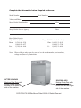
Simply Engineered Better
Technical Manual
Undercounter
Dishwasher
Model
301HT
High Temperature
with Built-in Booster
Machine Serial No.
June, 2005
Manual P/N
P. O. Box 4183
Winston-Salem, North Carolina 27115-4149
336/661-1992
Fax: 336/661-1660
113648 Rev H
2674 N. Service Road
Jordan Station, Ontario, Canada L0R 1S0
905/562-4195
Fax: 905/562-4618
www.moyerdiebel.com
Complete the information below for quick reference.
Model Number
Serial Number
Voltage and Phase
Moyer Diebel Parts Supplier
Phone
Moyer Diebel Service Agency
Phone
Moyer Diebel Service:
Moyer Diebel (USA)
Phone: 1 (336) 661-1556
1 (800) 858-4477
Fax:
1 (336) 661-1660
Moyer Diebel Limited (Canada)
Phone: 1 (905) 562-4195
1 (800) 263-5798
Fax: 1 (905) 562-4618
Note: When calling to order parts, be sure to have the model number, serial number,
voltage and phase of your machine.
AFTER S/N 45420
Machine Data Plate with
model & serial number
located on the lower left
side of the machine.
S/N 45368-45419
Machine Data Plate with
model & serial number
located on the lower right
side of the machine.
COPYRIGHT © 2005 by Moyer Diebel (USA). All Rights Reserved.
REVISION RECORD
Revision Record
Revision
Date
Revised
Pages
Serial Number
Effectivity
Comments
7/3/03
All
——
10/2/03
2, 30-31
Inserted pressure reducing valve
information (107550).
10/14/03
22-23
Inserted rinse aid dispenser parts
breakdown information.
10/14/03
33
Revised part number for solenoid
valve.
2/11/04
16
Revised part number for door
support.
8/4/04
14-15
Added new hardware for panels.
8/4/04
16-17
Added new hardware for control
cabinet decal.
1/18/05
14
1/18/05
16-17
Added part numbers for hardware.
1/18/05
21
Replaced P/N 436348 with 113604
and H36157 with 0510821.
1/18/05
23
Added P/N’s for rinse aid and
detergent labels.
1/18/05
31
Replaced P/N H33402 with 109985.
1/18/05
36-37
54257-54304
6/6/05
16-17
60605
First issue of manual and
replacement parts lists
Added door gasket H36353.
Added new control panel.
Added new drawing and part numbers
to door rod plate.
i
REVISION RECORD
Revision Record (Cont.’)
ii
LIMITED WARRANTY
Limited Warranty
Moyer Diebel, P.O. Box 4183, Winston-Salem, North Carolina 27115, and P. O. Box 301, 2674 North Service
Road, Jordan Station, Ontario, Canada L0R 1S0 warrants machines, and parts, as set out below.
Warranty of Machines: Moyer Diebel warrants all new machines of its manufacture bearing the name
“Moyer Diebel” and installed within the United States and Canada to be free from defects in material and workmanship for a period of one (1) year after the date of installation or fifteen (15) months after the date of shipment by
Moyer Diebel, whichever occurs first. [See below for special provisions relating to Model Series DF and SW.] The
warranty registration card must be returned to Moyer Diebel within ten (10) days after installation. If warranty card
is not returned to Moyer Diebel within such period, the warranty will expire after one year from the date of shipment.
Moyer Diebel will not assume any responsibility for extra costs for installation in any area where there are
jurisdictional problems with local trades or unions.
If a defect in workmanship or material is found to exist within the warranty period, Moyer Diebel, at its election, will either repair or replace the defective machine or accept return of the machine for full credit; provided,
however, as to Model Series DF and SW, Moyer Diebel’s obligation with respect to labor associated with any repairs shall end (a) 120 days after shipment, or (b) 90 days after installation, whichever occurs first. In the event that
Moyer Diebel elects to repair, the labor and work to be performed in connection with the warranty shall be done
during regular working hours by a Moyer Diebel authorized service technician. Defective parts become the property
of Moyer Diebel. Use of replacement parts not authorized by Moyer Diebel will relieve Moyer Diebel of all further
liability in connection with its warranty. In no event will Moyer Diebel’s warranty obligation exceed Moyer
Diebel’s charge for the machine. The following are not covered by Moyer Diebel’s warranty:
a.
b.
c.
d.
e.
f.
g.
h.
i.
j.
Lighting of gas pilots or burners.
Cleaning of gas lines.
Replacement of fuses or resetting of overload breakers.
Adjustment of thermostats.
Adjustment of clutches.
Opening or closing of utility supply valves or switching of electrical supply current.
Adjustments to chemical dispensing equipment.
Cleaning of valves, strainers, screens, nozzles, or spray pipes.
Performance of regular maintenance and cleaning as outlined in operator’s guide.
Damages resulting from water conditions, accidents, alterations, improper use, abuse,
tampering, improper installation, or failure to follow maintenance and operation procedures.
Examples of the defects not covered by warranty include, but are not limited to: (1) Damage to the exterior or
interior finish as a result of the above, (2) Use with utility service other than that designated on the rating
plate, (3) Improper connection to utility service, (4) Inadequate or excessive water pressure, (5) Corrosion
from chemicals dispensed in excess of recommended concentrations, (6) Failure of electrical components due
to connection of chemical dispensing equipment installed by others, (7) Leaks or damage resulting from such
leaks caused by the installer, including those at machine table connections or by connection of chemical dispensing equipment installed by others, (8) Failure to comply with local building codes, (9) Damage caused by
labor dispute.
Warranty of Parts: Moyer Diebel warrants all new machine parts produced or authorized by Moyer Diebel to be
free from defects in material and workmanship for a period of 90 days from date of invoice. If any defect in material and workmanship is found to exist within the warranty period Moyer Diebel will replace the defective part without charge.
DISCLAIMER OF WARRANTIES AND LIMITATIONS OF LIABILITY. MOYER DIEBEL’S WARANTY
IS ONLY TO THE EXTENT REFLECTED ABOVE. CHAMPION MAKES NO OTHER WARRANTIES,
EXPRESS OR IMPLIED, INCLUDING, BUT NOT LIMITED, TO ANY WARRANTY OF
MERCHANTABILITY, OR FITNESS OF PURPOSE. MOYER DIEBEL SHALL NOT BE LIABLE FOR
INCIDENTAL OR CONSEQUENTIAL DAMAGES. THE REMEDIES SET OUT ABOVE ARE
THE EXCLUSIVE REMEDIES FOR ANY DEFECTS FOUND TO EXIST IN MOYER DIEBEL
DISHWASHING MACHINES AND MOYER DIEBEL PARTS, AND ALL OTHER REMEDIES ARE EXCLUDED, INCLUDING ANY LIABILITY FOR INCIDENTALS OR CONSEQUENTIAL DAMAGES.
Moyer Diebel does not authorize any other person, including persons who deal in Moyer Diebel Dishwashing
Machines to change this warranty or create any other obligation in connection with Moyer Diebel Dishwashing
Machines.
iii
FIV
FOREWORD
1. Read the instructions in this manual carefully. It contains important information on
installation, operation, and safety.
2. Store this manual carefully for future reference.
3. After removing packing material, check for loose parts in dishracks.
4. Before switching the equipment on, make sure that the model data plate conforms
to the electrical and water requirements supplied to this particular machine.
5. Installation should be carried out by qualified personnel according to the manufacturers instructions. The installation of your machine must meet all applicable
health and safety codes.
6. This equipment should be used for its intended purpose. Any other application
should be considered improper and therefore dangerous.
7. Only trained personnel should operate this equipment.
8. Operators must strictly follow all hygienic requirements in the handling of clean
dishware or cutlery.
9. Do not leave the machine in an environment at temperatures
lower than 0°C/32°F.
10. This machine should not be washed with a direct water stream.
11. Only qualified personnel should access the control panel after disconnecting
main power supply. Tag the disconnect indicating work is being performed
on that circuit.
12. Noise level of the machine is less than 67dB.
The manufacturer declines any responsibility for any printing errors contained in this
booklet.
The manufacturer also reserves the right to make any modifications to its products that do
not affect the basic characteristics thereof.
iv
TAB LE OF C ONT E NT S
TABLE OF CONTENTS
R evision R ecord...........................................................................................................
L imited Warranty .........................................................................................................
Forward........................................................................................................................
PAGE
i
iii
iv
1
OPERATION ................................................................................. 5
MAINTENANCE ........................................................................... 7
REPLACEMENT PARTS ............................................................... 13
ELECTRICAL SCHEMATICS ........................................................ 41
INSTALLATION ............................................................................
LIST OF FIGURES
Figure
Figure
Figure
Figure
Figure
Figure
Figure
Figure
Figure
Figure
Figure
Figure
Figure
Figure
Figure
Figure
1
2
3
4
5
6
7
8
9
10
11
12
13
14
15
16
–
–
–
–
–
–
–
–
–
–
–
–
–
–
–
–
Control Panel Detail ...............................................................................
Power Switch Position ............................................................................
Drain Switch Position .............................................................................
Hood and Tank ........................................................................................
Door A ssembly .......................................................................................
Wash and R inse A rms .............................................................................
Tank Components ...................................................................................
R inse A id Dispenser ...............................................................................
Wash and R inse Spray A rms ..................................................................
Wash and R inse Piping ...........................................................................
Pump/Motor A ssembly ...........................................................................
B ooster A ssembly ..................................................................................
Fill Piping A ssembly ..............................................................................
Control Panel (Prior to Serial Number 54256 and A fter 54305)............
Control Panel (Serial Number R ange 54257 to 54304) .........................
Control Cabinet ......................................................................................
5
7
7
14
16
18
20
22
24
26
28
30
32
34
36
38
v
Part 1:
INSTALLATION AND MAINTENANCE
This Page
Intentionally
Left
Blank
vi
INSTALLATION
GENERAL
This manual covers the Moyer Diebel 301 undercounter high temperature dishwashing machine
with built-in booster. Liquid detergent and rinse aid dispensing pumps are standard. Even though
chemical dispensing settings are preset at the factory for average water conditions, to ensure
maximum performance and best results, have your chemical supplier perform a water titration
test and adjust dispensing pumps for your specific water conditions.
INSTALLATION AND MAINTENANCE
The following instructions are addressed to qualified personnel. Repairs should be performed by authorized personnel using parts supplied by the manufacturer.
NOTE:
Installation must allow for the ability to remove machine for servicing.
UNPACKING
WARNING:
Care should be taken when lifting the machine to prevent damage.
The machine is normally shipped on a skid enclosed by straps. When transporting the machine,
use a lift truck or fork lift, positioning the box properly on the forks.
1. Immediately after unpacking your machine, inspect for any shipping damages. If damage is
found, save the packing material and contact the carrier immediately.
2. Remove the dishwasher from the skid. Adjust the feet if required, then move the machine to
its permanent location.
3. Level the machine (if required) by placing a level on the top if the machine and adjusting the
feet. Level the machine front-to-back and side-to-side.
4. Remove any foreign material from inside of the machine.
!
CAUTION:
After locating your machine, it must meet with all local health codes. Consult your local
health department representative to ensure compliance.
1
INSTALLATION
INSTALLATION (CONT.)
ELECTRICAL CONNECTIONS
NOTE:
Leave enough electrical cable behind the machine so that the dishwasher can be pulled
forward a minimum of two feet to be serviced.
WARNING:
Electrical and grounding connections must comply with the National Electrical Code and/or
Local Electrical Codes.
WARNING:
When working on the dishwasher, disconnect the electric service and tag it to indicate work
is being done on that circuit.
1. The electrician should compare the electrical specifications on the machine electrical data
plate (located in the control panel) to the electrical power supply before connecting the
machine to the incoming service at a fused disconnect switch.
NOTE:
The 208-240V/60Hz/1PH electrical supply service for this machine must be a 2-wire plus
ground service. For optional 208-240V/60Hz/3PH the electrical supply service must be a 3wire plus ground service.
2. On the 208V-240V models, a knockout is provided at the rear of the junction box for
electrical service connections. A fused disconnect switch or circuit breaker (supplied by
user) is required to protect each power supply circuit.
PLUMBING CONNECTIONS
!
CAUTION:
Plumbing connections must comply with local health and plumbing codes.
Water Connections
1. Connect the hot water supply to the fill hose provided with a 3/4" NPT fitting.
2. Install a manual shut-off valve in the water supply line to accommodate servicing the
machine. The shut-off valve should be the same size or larger than the supply line.
3. Install a 3/4" pressure reducing valve (PRV) (supplied with machine) in the water supply
line, and set at 22PSI/151kPa.
2
INSTALLATION
INSTALLATION (CONT.)
PLUMBING CONNECTIONS (CONT.)
Drain Connections
1. Drain hose must be supported by bracket provided (shipped inside of machine).
2. The drain hose bracket must be mounted a minimum of 2 feet above the finished drain,
either on the rear of the machine or on the wall.
3. The maximum height of the drain from the floor must not exceed 3 feet.
4. Connect the 3/4"I.D. flexible reinforced drain hose to a 1-1/2" wye (Y) drain fitting. Use a
3/4" hose adapter (supplied by others). Do not connect drain hose to a 90° drain fitting.
DETERGENT
The machine is equipped with an automatic detergent dispensing pump system.
1. Use a qualified detergent/chemical supplier for your detergent and rinse aid needs.
2. Your machine is supplied with a detergent dispensing pump that is internally wired and ready
for use. Use a commercial grade liquid detergent and insert the red pickup tube into the
detergent container. The pickup tube has a strainer on the end to prevent the crystallized
chemical from clogging the supply lines.
!
CAUTION:
Always wash the hands under running water if they come into contact with the detergent and
comply with the specific instructions pertaining to the specific type of detergent.
NOTE:
A nonchlorinated detergent is recommended for your dishwasher.
To prime the peristaltic pump:
1. Insert pump inlet hose into the detergent container.
2. Close machine door and switch machine on.
3. Allow wash tank to fill and run machine cycles until chemical enters machine.
RINSE AID
1. Use a qualified/chemical supplier for your rinse aid needs.
2. Insert the transparent tube into the container containing the rinsing agent.
3. Prime the rinse aid pump while machine is in cycle by pressing and depressing power button
until the transparent tube has completely filled.
3. Start the machine as described the "OPERATION SUMMARY" on page 5. The dispenser
will pump about 3cc of liquid from the container.
3
INSTALLATION
INSTALLATION (CONT.)
COMPLETING THE INSTALLATION
1. Recheck for and remove any foreign materials from inside the machine.
2. Center the scrap screens over the sump opening
3. After Plumbing and electrical connections are completed, check machine for water leaks by
closing the door, then depressing the ON switch. This allows the tank to begin filling and to
reach temperature.
4. Open the door and check the water level. The water level should be a two inches above the
scrap screen.
5. Close the door (the machine has a door safety switch and will not start until the door is
closed.
4
OPERATION
OPERATION
OPERATION SUMMARY
The following is a summary of your model 301HT dishwasher operating cycle:
1. The door must be closed to begin the cycle.
2. Pressing the POWER button begins to fill the wash
tank.
3. When the correct water level has been reached the
booster heater comes on.
Figure 1-Control Panel
4. Press and holding the START button starts the cycle.
5. The pump runs during the wash cycle for approximately
120 seconds. The wash cycle duration is extended if the booster water temperature does
not reach 180°F/82°C
6. After a 5 second pause, the fill valve opens and the rinse cycle starts.
7. The machine rinses for 15 seconds. The cycle light turns off after 7 seconds indicating that
the cycle is complete. DO NOT open the door until the cycle lamp turns off.
8. Open the door and remove the rack of clean ware.
OPERATION PROCEDURES
The operation of your dishwasher will be more efficient when these procedures are followed:
1. Check that the spray arms, overflow tube and scrap screens are in place.
2. Close the door. Press the POWER switch. The tank will begin to fill with water.
This procedure is only needed when the tank is empty.
3. When the tank is full, check the wash tank temperature gauge. Minimum wash temperature
is 66°C/150°F.
4. Scrap and preflush all items to be washed, load items into rack. Wash only one layer of
silverware in a rack at a time.
NOTE:
DO NOT OVERLOAD the rack.
5. Open the door and insert the rack into the machine.
6. Close the door . Press the START switch and hold for 1 second, then release. This will start
the wash cycle. The cycle lamp will light and will remain on until the entire wash/rinse cycle
has completed.
NOTE:
The machine may be stopped at any time during the cycle by opening the door. Closing the
door resumes from the point where it was interrupted in the cycle.
5
OPERATION
OPERATIONS (CONT.)
MAINTENANCE
7. Check the rinse temperature during the final rinse. The final rinse must be 82°C/180°F
minimum.
8. When the green cycle light turns off, the cycle is complete.
9. Open the door and remove the rack.
10. Repeat steps 4-9 for additional cycles. Machine operation is automatic.
11. Clean the scrap screens after every meal period. During heavy usage, the scrap screens
should be cleaned more frequently.
!
CAUTION:
Poor machine performance and/or damage to the machine can occur if the scrap screens
become clogged with soil or waste particles.
12. At the end of the day, any water in the tank should be drained pressing the POWER button to
turn machine off and remove the overflow tube. Then press the DRAIN switch to activate the
drain pump and completely drain the machine.
!
6
CAUTION:
DO NOT LEAVE WATER IN THE TANK OVERNIGHT. Water left in the tank overnight will
allow chemicals to deteriorate the tank.
MAINTENANCE
MAINTENANCE
The efficiency and life of your machine in increased be regularly scheduled preventive maintenance. A well maintained machine gives better results and service. An investment of a few
minutes of daily maintenance will be worthwhile.
The best maintenance you can provide is to keep your machine clean. Should poor results occur:
first drain, next clean the machine as described below in the Daily-Every 8 Hours procedure,
then refill.
Intervals shown in the following schedules represent an average length of time between necessary
maintenance. Maintenance intervals should be shortened whenever your machine is faced with
abnormal working conditions, hard water, or multiple shift operations.
CLEANING SCHEDULE
•Meal Periods
1. Press power switch OFF (See Fig.2).
2. Remove the overflow the press and hold
the DRAIN switch to drain the machine.
(See Fig. 3)
3. Wipe the interior to remove any debris.
Figure 2- Power Switch Position
4. Clean the screens after every meal period
and more frequently during heavy usage.
Do not allow screens to become clogged
with debris.
5. Inspect wash and rinse arms. Clean if
necessary.
Figure 3- Drain Switch Position
6. Replace overflow tube.
7. Close door.
8. Press the POWER button to refill machine. (See Fig. 2).
•Daily-Every 8 Hours
1. Remove the overflow tube and press the POWER switch to OFF (see Fig. 2) to drain the
tank.
2. Press and hold the DRAIN switch (see Fig. 3) to activate the drain pump and drain all the
water from the machine.
3. Open the door and remove both the upper and lower spray arms by unscrewing the knurled
fastener holding each arm.
4. Remove the scrap screen carefully to keep the debris from falling into the sump.
5. Clean the inside of the tank with clean water.
6. At a remote sink, back flush the screens until clean. Do not strike against solid objects.
7. Clean the wash and arms to remove any debris from the spray openings. Do not strike the
arms against solid objects.
8. Reinstall the scrap screens, overflow tube and the spray arms.
9. Leave the door open overnight to allow drying.
10. Report any unusual conditions to your supervisor.
7
MAINTENANCE
MAINTENANCE (CONT.)
CLEANING SCHEDULE (CONT.)
•As Required
1. Check temperature gauge readings. Replace as necessary.
2. Check chemical supplies and refill as necessary.
•Weekly
1. Inspect all water lines for leaks and tighten any joints of required.
2. Clean all detergent residue from exterior of machine.
3. Check drain for leaks.
4. Clean any accumulated scale from the heating element.
5. Remove and closely inspect each spray arm for any blockage.
6. Check for any damage to scrap screen. Ineffective screening can cause wash system failures.
7. Clean the detergent, and rinse aid supply tubes. Complete the following procedure:
a. Remove the detergent and rinse aid pick up tubes from the containers. Place the tubes into
a container of hot water.
b. Remove the pick up tubes from the hot water and reinsert them into the correct chemical
containers (red-detergent, clear-rinse aid). Repeat the original priming procedures to
ensure that the chemicals have filled the tubes for the next operating period.
c. Run a complete cycle to flush chemicals from the tank.
8
MAINTENANCE
MAINTENANCE (CONT.)
CLEANING SCHEDULE (CONT.)
DELIMING
Your dishwasher should be delimed regularly as required. This will depend on the mineral
content of your water.
Inspect the machine interior for lime deposits. If deliming is required, a deliming agent should be
used for best results.
Carefully follow the following procedure to preform deliming:
WARNING:
Deliming solution or other acids must not come in contact with household bleach (sodium
hypochlorite) or any chemicals containing chlorine, iodine, bromine or fluorine. Mixing will
cause hazardous gases to form. Skin contact with deliming solutions can cause severe
irritation and possible chemical burns. Consult your chemical supplier for specific safety
precautions.
1. Add the delime chemical to the wash tank (per the chemical supplier specifications).
2. Close the door.
3. Press the POWER switch to fill the machine, then press the START switch to run through a
complete cycle.
4. When cycle is complete press the POWER switch to the OFF position, open the door and
remove the overflow tube to drain the tank, then press and hold the DRAIN switch to
drain the machine.
5. Replace overflow tube. Close door.
6. Repeat steps 3 - 5 to ensure all delime chemicals are purged from machine.
7. Deliming is now complete.
9
TROUBLESHOOTING
TROUBLESHOOTING
Before determining any specific cause of a breakdown or abnormal operation of your dishwasher,
check that:
1. All switches are turned on.
2. Wash and rinse arms are clean and clear of any debris.
3. Overflow tube is properly positioned.
4. Scrap screen is properly positioned and clean.
5. Thermostats are at the correct settings.
6. Detergent and rinse additive dispensers are adequately filled.
7. All plumbing valves to machine are open.
If a problem still exists, use the following table for troubleshooting.
CONDITION
Machine will not start
CAUSE
SOLUTION
Main switch disconnected ............... Turn on switch.
Door not closed ................................ Make sure doors are fully closed.
Door safety switch faulty ................ Contact your service agency
Start switch faulty ............................ Contact your service agency
Low or no water
10
Main water supply is turned off ......
Drain/overflow tube is not
in place and seated ...........................
Machine doors not fully closed .......
Faulty fill valve ...............................
Turn on house water supply
Place and seat drain/overflow tube
Close doors securely
Contact your service agency
Continuous water filling
Fill valve will not close ...................
Drain/overflow tube not in place ....
Air trap lost pressure .......................
..........................................................
Contact your service agency
Install drain/overflow tube in tank
Drain machine, reinsert overflow tube
and refill machine.
Motor not running
Defective motor ............................... Contact your service agency
Wash tank water temperature
is low when in use
Incoming water temperature
at machine too low ..........................
Defective thermometer ....................
Defective thermostat .......................
Defective heater element .................
Raise temperature to 140°F
Check or replace
Check for proper setting or replace
Check or replace
TROUBLESHOOTING
TROUBLESHOOTING (CONT.)
CONDITION
CAUSE
SOLUTION
Insufficient pumped spray
pressure
Clogged pump intake screen ...........
Clogged spray pipe ..........................
Scrap screen full ..............................
Low water level in tank ...................
Defective pump seal ........................
Clean
Clean
Must be kept clean and in place
Check drain and overflow tube
Contact service agent
Insufficient final rinse or no
final rinse
Clogged rinse nozzle and/or arm .... Clean with paper clip/delime
Clogged strainer ............................... Clean or replace
Low final rinse temperature
Low incoming water ........................ Check the booster be sure the thermostat is set
temperature ...................................... to maintain 180°F/82°C temperature.
Check fill valve operation.
Defective thermometer .................... Check for proper setting or replace
Poor washing results
Detergent dispenser not
operating properly ........................... Contact detergent supplier
Insufficient detergents ..................... Contact detergent supplier
Food Soil concentration too
high in wash tank ............................. Drain tank, clean and refill every 2 hours of
operation or after each meal period.
Wash water temperature
too low ............................................. See condition “Wash Tank
Water Temperature” above
Wash arm clogged ........................... Clean
Wash arm not rotating ..................... Clean arm. Check bearing, replace if
.......................................................... necessary.
Improperly scrapped dishes ............ Check scrapping procedures
Ware improperly
placed in rack ................................... Use proper racks. Do not overload racks
Improperly cleaned
equipment ........................................ Unclog wash sprays and rinse nozzles
to maintain proper pressure and flow
conditions. Overflows must be open.
Keep wash water as clean as possible.
Heating element has soil/lime
buildup ............................................. Clean and/or delime.
Detergent pick up tube in
incorrect container ........................... Place RED pick up tube in detergent container.
11
This Page
Intentionally
Left
Blank
12
REPLACEMENT PARTS
REPLACEMENT
PARTS
13
REPLACEMENT PARTS
11
1
10
7
11
2
12
12
13
A
7
3
12
7
3
11
9
8
12
4
11
5
7
6
Figure 4- Hood and Tank
14
REPLACEMENT PARTS
HOOD AND TANK
Fig. 4
Item No.
1
2
3
4
5
6
7
8
9
10
11
12
13
Part
No.
H36145
H36147
H35551
H36151
H33576
H25209
H25697
H36146
H25693
H36148
H36728
H450821
H36353
A
H25744
H25774
Part Description
Panel, Control Cabinet ..................................................................
Panel, Side RH ..............................................................................
Tracks, Rack ..................................................................................
Panel, Front ...................................................................................
Bottom Panel .................................................................................
Foot, Adjustable ............................................................................
Self-Tapping Screw 9 x 13 ............................................................
Panel, Side LH ..............................................................................
Self-Tapping Screw Bevel 2 x 13 ..................................................
Panel, Back....................................................................................
Screw TS M5 x 20 ........................................................................
Spring Clip Fastener 5MA .............................................................
Door, Gasket Top ...........................................................................
Qty
1
1
2
1
1
4
12
1
4
1
6
8
1
HARDWARE FOR TRACKS (Quantities per track)
Washer ...........................................................................................
Nut .................................................................................................
2
2
15
REPLACEMENT PARTS
1
2
3
14
A
15
16
4
A
5
A
16
4
5
6
A
8
7
8
10
9
12
11
12
Figure 5- Door Assembly
16
REPLACEMENT PARTS
DOOR ASSEMBLY
Fig. 5
Item No.
1
2
3
4
5
6
7
8
9
10
11
12
13
14
15
16
Part
No.
H25791
106486
107623
H160909
H160837
H34144
H15568
H30438
H33336
H25693
H36149
H33277
H32969
H35171
H260223
H37104
A
H33387
H30194
Part Description
Nut Plain .......................................................................................
Washer ..........................................................................................
Nut Door Support ..........................................................................
Door Rod Plate ..............................................................................
Gasket ...........................................................................................
Door Rod .......................................................................................
Door Dowels .................................................................................
Door Spring ...................................................................................
Door Catch ....................................................................................
Self-Tapping Screw Bevel 2 x 13 ..................................................
Door Assembly Complete .............................................................
Self-tapping Screw TSP 2.9 x 9.5 .................................................
Door Magnet .................................................................................
Washer ..........................................................................................
Screw Inox TB 5 x 12 ...................................................................
Door Rod Plate Support ................................................................
Qty
2
2
2
2
2
2
2
2
1
2
1
2
1
2
2
2
HARDWARE FOR DOOR PLATE (Quantities per door plate)
Screw ............................................................................................
Hex, Nut ........................................................................................
2
2
17
REPLACEMENT PARTS
1
2
3
4
1
5
6
6
8
9
7
8
6
7
6
5
1
4
9
2
3
1
Figure 6- Wash and Rinse Arms
18
REPLACEMENT PARTS
WASH AND RINSE ARMS
Fig. 6
Item No.
1
2
3
4
5
6
7
8
9
Part
No.
112551
112549
112793
112550
H34998
H190663
H36257
H36275
H36211
Part Description
Bearing, Wash Arm .......................................................................
Hub, Wash Arm .............................................................................
Wash Arm ......................................................................................
Locknut, Wash Arm ......................................................................
Nut Spacer .....................................................................................
Bushing, Rinse Arm ......................................................................
Rinse Nozzle .................................................................................
Pin, Revolving Rinse Arm ............................................................
Rinse Arm 301 ..............................................................................
Qty
4
2
2
2
2
4
6
2
2
19
REPLACEMENT PARTS
1
2
3
9
4
8
7
4
13
4
4
11
10
12
16
15
14
Figure 7- Tank Components
20
5
6
REPLACEMENT PARTS
TANK COMPONENTS
Fig. 7
Item No.
1
2
3
4
5
6
7
8
----9
10
11
12
----13
14
15
16
Part
No.
H35162
113604
H36351
H34982
H441402
H460344
H36154
H34358
0510821
H180726
H36271
H36343
H15229
H35388
H00166
H180726
H25092
H25417
H36397
H33745
Part Description
Heater 2000W 230V .....................................................................
Thermostat Handle ........................................................................
Support Plate, for Thermostat Handle ...........................................
Screw M5 X 12 Half Round Head ................................................
Pressure Gauge .............................................................................
Plate Adhesive, Thermometer .......................................................
Bracket, Pressure Gauge ..............................................................
Detergent, Peristallic Pump ...........................................................
Hose, Noprene Pump 1/4 ID x 5/16 ..............................................
Strainer ..........................................................................................
Bracket, Detergent Pump .............................................................
Bracket, Rinse Aid Pump ..............................................................
Lock Nut Aid .................................................................................
Rinse Aid Dispenser ......................................................................
Tube (Transparent) ........................................................................
Strainer ..........................................................................................
Knob, Thermostat ..........................................................................
Adjustable Thermostat 30°C-90°C/86°F-194°F (Wash) ...............
Thermostat 30°C-95°C/86°F-203°F(Rinse) ..................................
Hi Limit Thermostat ......................................................................
Qty
1
1
4
A/R
1
1
1
1
A/R
1
1
1
1
1
A/R
1
2
1
1
1
21
REPLACEMENT PARTS
12
11
13
10
14
9
15
6
8
7
5
4
16
3
18
2
19
1
21
20
22
Figure 8- Rinse Aid Dispenser
22
17
REPLACEMENT PARTS
RINSE AID DISPENSER
Fig. 8
Item No.
1
2
3
4
5
6
7
8
9
10
11
12
13
14
15
16
17
18
19
20
21
22
___
___
___
Part
No.
Part Description
H15229
Locknut, Rinse Aid Dispenser ......................................................
H25757
Spacer Slotted ...............................................................................
H36343
Support, Rinse Aid Dispenser .......................................................
H200117 Rubber Hose ..................................................................................
H33424
Hose Clamp ...................................................................................
H35392
90° Fitting Vlave, Rinse Aid .........................................................
H25211
Valve, Non Return Rinse Aid .......................................................
H32831
Gasket ............................................................................................
H28252
Dispenser Suction Fitting ..............................................................
H31643
Hose Clip ......................................................................................
H00166
Hose, Transparent ..........................................................................
H00182
Hose, Blue .....................................................................................
H25803
Hose Clip 13-20 ABA ...................................................................
H32280
Screw, Rinse Aid Dispenser Pump Housing .................................
H25047
Rinse Aid Dispener Back Housing ...............................................
H31596
Rinse Aid Dispenser Back Housing Gasket ..................................
H31991
Rinse Aid Pump Seal ....................................................................
H25818
Rinse Aid Dispenser Pump Spring ...............................................
H32243
Gasket ............................................................................................
H25046
Rinse Aid Dispenser Pump Housing ............................................
H25251
Oring .............................................................................................
H18394
Adjusting Screw, Rinse Aid Dispensing Pump ............................
H35388
H29521
H29522
Qty
1
1
1
A/R
1
1
2
2
1
1
A/R
A/R
1
8
1
1
1
1
1
1
2
1
Rinse Aid Dispenser (Includes items 1-9, 14-22)
Rinse Label
Detergent Label
23
REPLACEMENT PARTS
1
2
3
4
6
8
9
5
7
18
13
17
14
14
10
11
20
19
12
16
14
15
Figure 9- Drain Assembly
24
REPLACEMENT PARTS
DRAIN ASSMEBLY
Fig. 9
Item No.
1
2
3
4
5
6
7
8
9
10
11
12
13
14
15
16
17
18
19
20
Part
No.
H32796
H32795
H36160
H35895
H25684
H35896
H32719
H25006
H34790
H26637
H31423
H32715
H30421
H25807
H32894
H32801
H36032
H35544
H35359
H28226
Part Description
Cover, Round Filter ........................................................................
Bottom, Round Filter .....................................................................
Overflow Tube, Drain Pump .........................................................
Scrap Screen .................................................................................
Self-Tapping Screw 9 x 9 ..............................................................
Sump Cover ...................................................................................
Rubber Sump .................................................................................
Nut, Drain Suction .........................................................................
Drain Elbow Series ........................................................................
Flat Gasket Drain ..........................................................................
Flat Gasket Suction ........................................................................
90° Suction Elbow .........................................................................
Drain Fitting Long .........................................................................
Clamp, Hose ..................................................................................
Suction Hose .................................................................................
Suction Sleeve, Drain Pump ..........................................................
Drain Pipe .....................................................................................
Drain Pump ...................................................................................
Bracket, Drain Pump .....................................................................
O-ring, Gasket ...............................................................................
Qty
1
1
1
1
1
1
1
1
1
1
1
1
1
4
1
1
1
1
1
1
25
REPLACEMENT PARTS
2
1
3
4
5
6
7
BOTTOM OF TANK
8
5
4
A
9
10
11
12
13
14
A
Figure 10- Wash and Rinse Piping
26
REPLACEMENT PARTS
WASH AND RINSE PIPING
Fig. 10
Item No.
1
2
3
4
5
6
7
8
9
10
11
12
13
14
A
Part
No.
H25807
110215
H35509
H25803
H00182
H35550
H36279
109466
H36280
H25808
H34828
H25809
H32894
H29043
Part Description
Jubilee Clip ...................................................................................
Screw SS .......................................................................................
Hub, Upper Arm ...........................................................................
Clamp, Hose ..................................................................................
Hose, Blue Rinse ...........................................................................
Wash Delivery Sleeve ....................................................................
Lower Column ..............................................................................
O-ring ............................................................................................
Lower Holder Revolving Arm ......................................................
Clamp, Hose ..................................................................................
Clamp, Hose ..................................................................................
Clamp, Hose ..................................................................................
Suction Hose .................................................................................
Capacitor 16 UF/450V ..................................................................
Qty
1
1
1
2
A/R
1
1
1
1
1
1
1
1
1
HARDWARE FOR MOUNTING PUMP
H25751
H25745
H25730
Split Spacer ................................................................................... 8
Lock Washer .................................................................................. 8
Hex Screw M8 x 25 ...................................................................... 4
27
REPLACEMENT PARTS
5
4
3
2
1
Figure 11- Pump Assembly
28
REPLACEMENT PARTS
PUMP ASSEMBLY
Fig. 11
Item No.
1
2
3
4
5
-
Part
No.
H36354
H26224
H26204
H36355
H36356
Part Description
Pump Body ...................................................................................
Gasket Pump Body .......................................................................
Impeller .........................................................................................
Shaft Seal ......................................................................................
Flange Wash Pump........................................................................
Qty
1
1
1
1
1
H36129
Wash Pump Assy Complete ..........................................................
1
29
REPLACEMENT PARTS
1
6
2
5
7
3
5
6
Figure 12- Booster Assembly
30
8
4
REPLACEMENT PARTS
BOOSTER ASSMEBLY
Fig. 12
Part
Item No.
No.
1
H36250
H33400
2
H161123
3
109985
4
H35816
5
H25803
6
H00182
7
H36150
8
H34192
Part Description
Heater 4000W 230/380V (40° Rise) .............................................
Heater 6000W 230/380V (70° Rise) .............................................
Element Cap ..................................................................................
Oring ..............................................................................................
Rinse Aid Inlet Fitting ....................................................................
Clamp, Hose ..................................................................................
Hose, Blue .....................................................................................
Booster Tank (Tank Only) .............................................................
Gasket ...........................................................................................
Qty
1
1
1
1
1
2
A/R
1
1
31
REPLACEMENT PARTS
5
1
2
2
3
3
4
4
4
3
6
9
7
6
3
11
8
10
3
28
13
4
14
12
26
15
27
17
18
18
NOT SUPPLIED
16
19
25
19
3
4
20
24
22
23
Figure 13- Fill Piping Assembly
32
21
4
REPLACEMENT PARTS
FILL PIPING ASSEMBLY
Fig. 13
Item No.
1
2
3
4
5
-6
7
8
9
10
11
12
13
14
15
16
17
18
19
20
21
22
23
24
25
26
27
28
Part
No.
H36156
H36361
H25803
H00182
100500
900836
H36170
H36173
H36289
H36288
H36290
H160121
H25239
H34733
H25011
H25778
H18472
H25263
H25010
H26629
H36172
H36349
H280607
H160117
H36032
H33344
H34996
H200415
107550
Part Description
Vacuum Breaker Mounting Box ....................................................
Hose Barb .....................................................................................
Clamp, Hose ..................................................................................
Hose, Blue .....................................................................................
Vacuum Breaker 1/2"NPT ............................................................
Repair*Kit 1/2" Vacuum Breaker .................................................
Hose Barb .....................................................................................
Cross Tee ......................................................................................
Right for Brass Insert ....................................................................
Brass Insert ...................................................................................
Raccord, Brass Insert ...................................................................
Hose Black ....................................................................................
Gasket ...........................................................................................
Clamp ............................................................................................
Cover for Air Trap .........................................................................
Nut, Injector ..................................................................................
Detergent Injector .........................................................................
Flat Gasket ....................................................................................
Air Trap .........................................................................................
Solenoid Valve 3/4" ........................................................................
Fitting .............................................................................................
Brass Reduction ............................................................................
Valve ..............................................................................................
Poly Tube .......................................................................................
Drain Hose ....................................................................................
Cable Clip ......................................................................................
Inlet Tube .......................................................................................
O-ring, Gasket ...............................................................................
Valve Press Reducing 3/4" ............................................................
Qty
1
2
A/R
A/R
1
A/R
3
1
1
1
1
A/R
1
1
1
1
1
1
1
1
1
1
1
A/R
1
1
1
1
1
33
REPLACEMENT PARTS
8
1
2
3
4
11
5
12
13
14
3
6
13
14
Figure 14- Control Panel
Prior to S/N 54256 & After S/N 54305
34
5
10
9
6
7
REPLACEMENT PARTS
CONTROL PANEL
(PRIOR TO 54256 & AFTER S/N 54305)
Fig. 14
Item No.
1
2
3
4
5
6
7
8
9
10
11
12
13
14
Part
No.
H36131
H35336
H32928
H35339
H32892
H32891
H35329
H35332
H35328
H35330
H35661
H32872
H450916
H460344
Part Description
Data Plate ......................................................................................
Cap, Drain Pushbutton ..................................................................
Lamp Neon Green .........................................................................
Cap Blank ......................................................................................
Neon Light Bulb Green .................................................................
Light Bulb Holder .........................................................................
Lamp Cover Green, Cycle ............................................................
Holder, 3 Position Gray ................................................................
Lamp Cover Green, Line ..............................................................
Key, Green Start ............................................................................
On/Off Green Key .........................................................................
Switch Single Pole ........................................................................
Thermometer .................................................................................
Plate Adhesive, Thermometer .......................................................
Qty
1
1
2
1
2
2
1
1
1
1
1
1
2
2
35
REPLACEMENT PARTS
4
7
9
4
1
6
11
AIN
DR
R
WE
PO
RT
STA
CY
CLE
3
SE
RIN
3
SH
WA
6
3
10
12
13
12
13
Figure 15- Control Panel
S/N Range 54256 to S/N 54304
36
3
3
8
2
5
2
REPLACEMENT PARTS
CONTROL PANEL
(S/N RANGE 54257 TO 54304)
Fig. 15
Item No.
1
2
3
4
5
6
7
8
9
10
11
12
13
Part
No.
H36648
H36799
H36795
H36801
H36798
H32891
H28870
H36797
H32892
H36796
H36800
H450916
H450916
Part Description
Data Plate .....................................................................................
Key, Black Drain ...........................................................................
Holder, D.25 Black ........................................................................
Push-buton, Double Pole Shunt .....................................................
Lamp Cover Clear D.25, Cycle ....................................................
Light Bulb Holder ..........................................................................
Light Bulb -Lux FM6, 3 230V .......................................................
Lamp Cover Green d.25, Line .......................................................
Neon Light Bulb Green .................................................................
On/Off Green D 25 Key ...............................................................
Switch Single Pole .........................................................................
Thermometer .................................................................................
Plate Adhesive, Thermometer .......................................................
Qty
1
2
5
2
1
2
1
1
1
1
1
2
2
37
REPLACEMENT PARTS
1
12
2
3
5
4
10
9
7
8
11
6
13
Figure 15- Control Cabinet
38
REPLACEMENT PARTS
CONTROL CABINET
Fig. 15
Item No.
1
2
3
4
5
6
7
8
9
10
11
12
13
Part
No.
H160121
H31643
H31171
H34312
H36142
H31982
H29175
H36357
H260248
H29281
H36278
H34046
H33188
Part Description
Hose, Black Rubber ......................................................................
Clamp, Hose ..................................................................................
Pressure Switch .............................................................................
Relay TA2SFA 16A 230V ............................................................
Timer 230V 60Hz .........................................................................
Booster Heater Contactor 220V 50Hz ..........................................
Terminal Block ..............................................................................
Switch, Continous Wash ...............................................................
Screw M5 x12 ...............................................................................
Terminal Block Earth (Ground) ....................................................
Threaded Bar, Electrical Connection ............................................
Drawer Stop Rope (Not Shown) ...................................................
Magnetic Switch (Not Shown) ......................................................
Qty
1
1
1
1
1
1
4
1
2
1
1
1
1
39
This Page
Intentionally
Left
Blank
40
Part 4:
ELECTRICAL
REPLACEMENT
SCHEMATICS
PARTS
PART 4:
ELECTRICAL
SCHEMATICS
41
ELECTRICAL SCHEMATICS
L1
1
208/230V/1 ~ 60HZ
HC1
1
40 41 42
BH
6/9KW
1
1
L2
1
2
GND
2
JMCALLISTER SCALE
SCALE
SHEET SH1 OF
1
3JUN03
CUSTOMER TO SUPPLY RATED VOLTAGE/PHASE/Hz,
AS SPECIFIED PER ORDER,TO DISCONNECT SWITCH.
ALL POWER SUPPLIED TO EACH CONNECTION POINT
MUST COMPLY WITH ALL LOCAL ELECTRIC CODES.
DR.BY
DATE
PSW
21
3
21
REV.
3
7
PS
4
4
5
7
7
6
8
18
HLTS
11
6
1CR
BTS
11
DESCRIPTION
21
1CR
M4
4
5
M1
M2
M3
6
6
6
6
3
12
9
11
6
9
10
5
8
HLTS
DSS
WTS
15
16
DATE
11
BY
STMD
8
REV.
21
9
PB
20
5
10
5
6
3
16
15
13
9
RV
DP
DRP
CD
MTR
TR
CL
PL
HC1
1CR
TH
DESCRIPTION
1
1
1
1
1
1
1
1
1
1
1
1
1
1
DATE
BY
DM1
DM2
DM3
DM4
0
2 SEC
3 SEC
5 SEC
TIMER SEQUENCE DIAGRAM
5 SEC
RINSE
SELF FEEDING
120 SEC WASH
5 SEC
*
150 SEC
10 SEC
DRIP PAUSE
15 SEC
0
* TIMER MOTOR OFF = DELAY FOR BOOSTER HEATING
AUXILLIARY RELAY
DESCRIPTION
1CR
BOOSTER HEATER ELEMENT
BOOSTER CONTACTOR
SYMBOL
BC1
BOOSTER THERMOSTAT
BH
BTS
CYCLE LIGHT
DETERGENT PUMP
CAPACITOR
DISCHARGE PUMP
CD
DP
CL
DRP
TANK HIGH LIMIT THERMOSTAT
DOOR CONTACT
BOOSTER SAFETY THERMOSTAT
DSS
HLTS
WASH PUMP MOTOR
TIMER CONTACTS
HTLS
M1/4
CYCLE START BUTTON
MTR
PB
PRESSURE SWITCH
ON/OFF BUTTON
POWER ON LIGHT
HOT WATER SOLENOID VALVE
PL
PSW
PS
RV
TANK HEATER ELEMENT
START MANUAL DRAIN
TANK THERMOSTAT
TIMER MOTOR
TH
TR
STMD
WTS
REV.
SCHEMATIC,301-HT
SINGLEPHASE
B 0510637
42
40
BH
41 42
1
2
GND
DR.BY
DATE
2
JMCALLISTER SCALE
SCALE
SHEET SH1 OF
1
22SEP03
CUSTOMER TO SUPPLY RATED VOLTAGE/PHASE/Hz,
AS SPECIFIED PER ORDER,TO DISCONNECT SWITCH.
ALL POWER SUPPLIED TO EACH CONNECTION POINT
MUST COMPLY WITH ALL LOCAL ELECTRIC CODES.
FOR 3 PHASE
DELTA CONNECTION
6/9KW BOOSTER HEAT
HC1
L1 L2 L3
230V/3 ~ 60HZ
1
PSW
3
21
REV.
21
3
PS
7
4
4
11
BTS
1CR
8
18
HLTS
11
6
DESCRIPTION
7
7
5
6
6
6
3
12
M1
M2
6
6
M3
5
1CR
M4
4
21
13
15
16
DATE
WTS
DSS
HLTS
8
5
10
9
6
11
9
BY
11
REV.
8
STMD
PB
9
21
5
20
13
15
16
3
6
5
10
TH
1CR
HC1
PL
CL
TR
MTR
CD
DRP
RV
DP
DESCRIPTION
9
1
1
1
1
1
1
1
1
1
1
DATE
1
1
1
1
BY
DM4
DM3
DM2
DM1
*
5 SEC
120 SEC WASH
5 SEC
RINSE
SELF FEEDING
5 SEC
TIMER SEQUENCE DIAGRAM
DESCRIPTION
ON/OFF BUTTON
15 SEC
TANK THERMOSTAT
WTS
REV.
10 SEC
B 0510727
0
SCHEMATIC,301-HT
THREEPHASE
TANK HEATER ELEMENT
TIMER MOTOR
TR
START MANUAL DRAIN
HOT WATER SOLENOID VALVE
TH
STMD
RV
PSW
PRESSURE SWITCH
POWER ON LIGHT
PL
PS
CYCLE START BUTTON
PB
WASH PUMP MOTOR
TIMER CONTACTS
MTR
BOOSTER SAFETY THERMOSTAT
M1/4
TANK HIGH LIMIT THERMOSTAT
DOOR CONTACT
DISCHARGE PUMP
DETERGENT PUMP
CYCLE LIGHT
CAPACITOR
HLTS
HTLS
DSS
DRP
DP
CL
CD
BOOSTER HEATER ELEMENT
BOOSTER THERMOSTAT
BTS
BOOSTER CONTACTOR
AUXILLIARY RELAY
BH
BC1
1CR
SYMBOL
150 SEC
DRIP PAUSE
* TIMER MOTOR OFF = DELAY FOR BOOSTER HEATING
3 SEC
2 SEC
0
ELECTRICAL
REPLACEMENT
SCHEMATICS
PARTS
43
REPLACEMENT PARTS
45