1
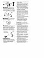
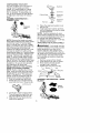
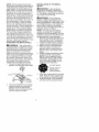
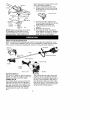
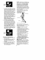
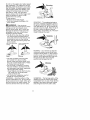
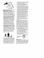
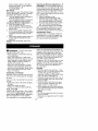
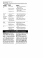
Instruction
Manual
I CRRFTSMRN°I
32cc/1.9 cu.in. 2-Cycle
GASOLINE BRUSHWACKER
®
Model No.
358.795180
•
Safety
•
Assembly
•
•
Operation
Maintenance
•
Parts List
•
Espa_ol
For Occasional
Use Only
DANGER:
Read and follow all Safety Rules and Operating
Instructions
before first use of this product.
For answers
Call 7 am-7
to your questions about this product:
pm, Mon.-Sat.,
or 10 am-7 pm, Sun.
1-800-235-5878
Sears,
530088128
Roebuck
12/3/01
and Co., Hoffman
<Hours listed are Central Time)
Estates,
IL 60179 U.S.A.
Warranty Statement
Safety Rules
Assembly
Operation
Maintenance
Service & Adjustments
2
2
5
8
13
14
Storage
Troubleshooting
Table
Emissions Statement
Parts List
Spanish
Parts and Ordering
FULL TWO YEAR WARRANTY ON CRAFTSMAN
BRUSHWACKER ® BLADED TRIMMER.
15
16
16
18
21
Back Cover
® GAS POWERED
For two years from the date of purchase, when this Craftsman Gas Powered
Brushwacker is maintained, lubricated, and tuned up according to the operating
and maintenance instructions in the instruction manual, Sears will repair, free of
charge, any defect in materials or workmanship.
This warranty excludes nylon line, spark plug, and air filter, which are expendable
parts and become worn during normal use.
If this Brushwacker is used for commercial purposes, this warranty applies for only 90
days from the date of purchase. If this Brushwacker is used for rental purposes, this
warranty applies for only 30 days from the date of purchase.
This warranty applies only while this product is in use in the United States.
WARRANTY SERVICE IS AVAILABLE BY RETURNING THE BRUSHWACKER TO THE
NEAREST SEARS STORE OR SERVICE CENTER IN THE UNITED STATES.
This warranty gives you specific legal rights, and you may also have other rights
which vary from state to state.
Sears, Roebuck and Co., D/817WA, H offman Estates, IL 60179
dlIIWARNING:
When using gardening appliances, basic safety precautions must always be followed to
reduce the risk of fire and serious
injury.
,_ DANGER:
This power tool can
be dangerous! This unit can cause serious injury including amputation or
blindness to the operator and others.
The warnings and safety instructions
in this manual must be followed to provide reasonable safety and efficiency
in using the unit. The operator is responsible for following the warnings
and instructions in this manual and on
the unit. Read the entire instruction
manual before assembling and using
the unit! Restrict the use of this unit to
persons who read, understand, and
follow the warnings and instructions in
this manual and on the unit. Never allow children to operate this unit.
INSTRUCTION
MANUAL
,_
DANGER:
SAFETY
ON THE
INFORMATION
UNIT
Blade can thrust vio-
lently away from material it does not
cut. Blade thrust can cause amputation of arms or legs. Keep people and
animals 50 feet (15 meters) away.
,_
WARNING:
Trimmer
line can
throw objects violently. You and others
can be blinded or injured. Wear safety
glasses and leg protection.
WEAR:
ALWAYS
Eye_
Thrown-'_
tt Protection
_ ObjectsI
.. LegGuards
Boots i_°_
A(}/LWARNING:
Hazard zone for
thrown objects. Blade/Trimmer line
can throw objects violently. Others can
be blinded or injured. Keep people
and animals 50 feet (15 meters) away.
___
_td
z°ne
_WARNING:
Do not use trimmer
head as a fastening device for the
blade.
WARNING:
The blade continues
to spin after the throttle is released or,
engine is turned off. The coasting blade
can throw objects or seriously cut if accidentally touched. Stop the blade by
contacting the right hand side of the
coasting blade with material already cut.
Stop coasting
blade by contact
with cut material.
®
OPERATOR SAFETY
• Dress properly. Always wear safety
glasses or similar eye protection when
operating, or performing maintenance
on your unit. (Safety glasses are
available.) Eye protection should be
marked Z87.
• Always wear face or dust mask if operation is dusty.
• Always wear heavy, long pants, long
sleeves, boots, and gloves. Wearing
safety leg guards is recommended.
• Always wear foot protection.
Do not
go barefoot or wear sandals.
• Secure hair above shoulder length.
Secure or remove loose clothing and
jewelry or clothing with loosely hanging ties, straps, tassels, etc. They can
be caught in moving parts.
• Being fully covered also helps protect
you from debris and pieces of toxic
plants thrown by spinning line/blade.
• Stay Alert. Do not operate unit when
you are tired, ill, upset or under influence of alcohol, drugs, or medication.
Watch what you are doing; use common sense.
• Wear hearing protection.
• Never start or run the engine inside
a closed room or building. Breathing
exhaust fumes can kill.
• Keep handles free of oil and fuel.
• Always use the handlebar and a
properly adjusted shoulder strap
with a blade (see ASSEMBLY).
UNIT/MAINTENANCE
SAFETY
_ILWARNING:
Stop unitand disconnect the spark plug before performing maintenance
(except carburetor adjustments).
• Look for and replace damaged or
loose parts before each use. Look
for and repair fuel leaks before use.
Keep unit in good working condition.
• Throw away blades that are bent,
warped, cracked, broken, or damaged in any other way. Replace trimmer head parts that are cracked,
chipped, broken, or damaged in any
other way before using the unit.
• Maintain unit according to recommended procedures. Keep blade
sharp. Keep cutting line at the proper
length.
• Use only Craftsman <_brand replacement line. Never use wire, rope,
string, etc.
• Install required shield properly before
using the unit. Use the metal shield
for all metal blade use. Use the plastic
shield for all line trimmer use.
• Use only specified blade or trimmer
head; make sure it is properly installed and securely fastened.
• Never start engine with clutch
shroud removed. The clutch can fly
off and cause serious injury.
• Besureblade
ortrimmer
head
stops Cutting on right side of the shield will
turning
when
engine
idles.
throw debris away from the operator.
• Make
carburetor
adjustments
with
• Use only in daylight or good artificial
thelower
endsupported
toprevent light.
blade
ortrimmer
linefromcontacting • Use only for jobs explained in this
manual.
anyobject.
Holdunitbyhand;
donot
usetheshoulder
strapforsupport. TRANSPORTING AND STORAGE
• Keep
others
away
whenmaking
car- • Stop the unit before carrying
buretor
adjustments.
away from your body
• Useonlyrecommended
Craftsman
_ • Keep muffler
the engine to cool and secure
accessories
andreplacement
parts. • Allow
the unit before storing or transport• Have
allmaintenance
andservice
not
ing it in a vehicle.
explained
inthismanual
performed
by • Empty the fuel tank before storing or
yourSears
Service
Center.
transporting the unit. Use up fuel left
FUEL
SAFETY
in the carburetor by starting the en• Mixandpour
fueloutdoors
gine and letting it run until it stops.
• Keep
away
fromsparks
orflames
• Store unit so the blade or line limiter
• Useacontainer
approved
forfuel
blade cannot accidentally cause in• Donotsmoke
orallow
smoking
near
jury. The unit can be hung by the
fuelortheunitorwhile
using
theunit
tube.
• Avoid
spilling
fueloroil Wipe
upall • Store unit out of reach of children.
fuelspillsbefore
starting
engine
SAFETY NOTICE: Exposure to vibra• Move
atleast10feet(3meters)
tions through prolonged use of gasoline
away
fromfueling
sitebefore
start- powered hand tools could cause blood
ingengine
or nerve damage in the fingers,
• Stopengine
andallowittocoolbe- vessel
hands, and joints of people prone to cirforeremoving
fuelcap
culation disorders or abnormal swell• Empty
thefueltankbefore
storing
or ings Prolonged use in cold weather
transporting
theunitUseupfuelleft has been linked to blood vessel daminthecarburetor
bystarting
theen- age in otherwise healthy people If
gineandletting it run until it stops
symptoms occur such as numbness,
• Store unit and fuel in area where fuel
vapors cannot reach sparks or open
flames from water heaters, electric
motors or switches, furnaces, etc
• Always store gasoline in a container
approved for flammable liquids
CUTTING SAFETY
WARNING:
Inspect the area to
be cut before each use Remove objects (rocks, broken glass, nails, wire,
string, etc.) which can be thrown or
become entangled in the Made or
trimmer head
• Keep others including children, animals, bystanders, and helpers at ]east
50 feet (15 meters) away Stop engine
immediately if you are approached
• Always keep engine on the righthand side of your body
• Hold the unit firmly with both hands
• Keep firm footing and balance Do
not overreach
• Keep blade or trimmer head below
waist ]eve] Do not raise engine
above your waist
• Keep all parts of your body away
from blade, trimmer head, and muffler when engine is running
A hot
muffler can cause serious burns
• Cut from your left to your right
pain, loss of strength, change in skin
color or texture, or loss of feeling in the
fingers, hands, or joints, discontinue the
use of this tool and seek medical attention An anti-vibration system does not
guarantee the avoidance of these problems Users who operate power tools
on a continual and regular basis must
monitor closely their physical condition
and the condition of this tool
SPECIAL NOTICE: This unit is
equipped with a temperature limiting
muffler and spark arresting screen
which meets the requirements of California Codes 4442 and 4443 All US
forest land and the states of California,
Idaho, Maine, Minnesota, New Jersey,
Oregon, and Washington require by law
that many internal combustion engines
be equipped with a spark arresting
screen If you operate in a locale where
such regulations exist, you are legally
responsible for maintaining the operating condition of these parts Failure to
do so is a violation of the law For normal homeowner use, the muffler and
spark arresting screen will not require
any service After 50 hours of use, we
recommend that your muffler be serviced or replaced by your Sears Service
Center
CARTON
CONTENTS
Check
carton
contents
against
thefollowing
list.
Model 358.795180
• Brushcutter
• Blade Shield Screws (4)
• Cupped Washer
• Large Nut for installing Blades
• Hex Wrench
• Metal Shield
• Plastic Shield
• Shoulder Strap with Warning
• 4-Point Weed Blade
• 8-Point Weed Blade
• Trimmer Head (assembled on unit)
• Handlebar (assembled on unit)
• Wing Nut (screwed onto shield)
• Container of line
• Container of oil
Examine parts for damage. Do not
use damaged parts.
NOTE: If you need assistance or find
parts missing or damaged, call
1-800-235-5878.
It is normal for the fuel filter to rattle in
the empty fuel tank.
Finding fuel or oil residue on muffler is
normal due to carburetor adjustments
and testing done by the manufacturer.
ASSEMBLY
_WARNING:
Always stop unit
and disconnect spark plug before performing any assembly procedures.
,_LWARNING:
If received
as-
sembled, repeat all steps to ensure
your unit is properly assembled and all
fasteners are secure.
TOOLS REQUIRED
• Hex Wrench (provided)
• Adjustable Wrench
ADJUST AND SECURE THE HANDLEBAR
DANGER:
To avoid serious injury, the barrier portion of the handlebar
must be adjusted and remain installed
as shown to provide a barrier between
operator and the spinning blade. The
handlebar clamp must be positioned
between the arrows on the handlebar
decal.
1. Lift handlebar to upright position.
Handlebar
2,
Rotate handlebar/clamp
counterclockwise toward engine until
clamp falls into groove of base.
Handlebar
Handlebar
Clamp ',,
Clamp
Base
3.
Place the handlebar in a comfortable position.
4. Retighten handlebar by turning
clamp knob clockwise until handlebar is secure and stationary in
clamp base (clamp knob can not
be overtightened).
ASSEMBLY OF SHOULDER
STRAP
WARNING:
Proper shoulder
strap and handlebar adjustments are
required before starting the engine.
1. Try on shoulder strap and adjust for
fit and balance before starting the
engine or beginning a cutting operation.
2. Insert your right arm and head
through the shoulder strap and allow it to rest on your left shoulder.
Make sure the danger sign is on
your back and the hook is to the
right side of your waist.
NOTE: A one-half twist is built in the
shoulder strap to allow the strap to rest
flat on the shoulder.
3. Adjust the strap, allowing the hook
to be about 6 inches below the
waist.
4. Fasten the strap hook to the clamp
located between the trigger handle
and the handlebar clamp base and
lift the tool to the operating position.
CONFIGURING
YOUR
UNIT
Youcanconfigure
yourunitusing
a
cutting
headforgrass
andlight
weeds,
oraweedblade
forcutting
grass,
weeds,
andbrush
upto1/2
inchindiameter.
Toassemble
your
unit,gotothesection
forthedesired
configuration
andfollow
theinstructions.
ASSEMBLY
INFORMATION
TRIMMER
HEAD
,,t-Gearbox
l_,_/---
Cutting Head. _
Hex Nut
TRIMMER
HEAD
NOTE: Remove the blade and metal
shield before attaching the plastic shield
and trimmer head. To remove blade,
push in locking lever and hold. Rotate
blade nut until the locking lever falls into
one of the grooves in the dust cup.
Continue to hold the locking lever. This
will keep the shaft from turning while
loosening the blade nut. Remove blade
nut by turning clockwise. Release locking lever. Remove both washers and
blade. To remove metal shield, loosen
and remove the four mounting screws.
See Aq-IACHING THE METAL SHIELD and
INSTALLATIONOF THE METAL BLADE for
illustrations. Be sure to store all parts
and instructions for future use.
INSTALLATION
OF THE CUTTING
HEAD (if not already installed)
NOTE: Before installing the trimmer
head, make sure the dust cup and retaining washer are positioned on the
shaft of the gearbox. The retaining
washer must be positioned with the
raised section toward the gearbox.
1. Push in locking lever and hold.
2. Rotate dust cup until the locking
lever falls into one of the grooves.
Dust Cup
WasherRetaining
Alignment
_=_"_..... Washer
_.,_
5.
Place the alignment washer over
the hex nut.
6. Install alignment washer and hex
nut by threading nut onto the shaft
counterclockwise.
NOTE: It will be necessary to use a
deep socket to tighten the hex nut. The
hex nut must be centered in the hole of
the cutting head before tightening.
7. Tighten nut securely (10-12 ft-lbs).
8. Release locking lever.
ATTACHING THE PLASTIC SHIELD
,_/kWARNING:
The shield must be
properly installed. The shield provides
partial protection from the risk of
thrown objects to the operator and
others and is equipped with a line limiter blade which cuts excess line to the
proper length. The line limiter blade
(on underside of shield) is sharp and
can cut you.
1. Remove wing nut from shield.
2. Insert bracket into slot on shield.
3. Pivot shield until bolt passes
through hole in bracket.
4. Tighten the wing nut securely.
Slot Bracket\ X
_'_,_
•
L>'-.
Shield
f-----_
......\_,N_'_d_) Wing Nut
ASSEMBLY
BLADES
INFORMATION
- WEED
Locking Lever
WEED
BLADES
3.
4.
Continue to hold in locking lever.
This will keep the shaft from turning while tightening the hex nut.
Slide the trimmer head onto the
shaft of the gearbox.
NOTE: Remove the trimmer head
and plastic shield before attaching the
metal shield and installing one of the
weed blades. To remove the trimmer
head, push in locking lever and hold.
Rotate trimmer head until the locking
lever falls into one of the grooves in
the dust cup. Continue to hold in locking lever. This will keep the shaft from
turning while loosening the hex nut
(the hex nut is located in the center of
the cutting head). It may be necessary to use a deep socket to loosen
the hex nut. Remove the hex nut by
turning clockwise.
Remove alignment
washer and trimmer head. Release
locking lever. To remove the plastic
shield, loosen and remove wing nut.
Pivot shield to release bracket from
slot. See INSTALLATION OF THE CUTTING HEAD and ATTACHING THE PLASTIC SHIELD for illustrations.
Be sure to
store all parts and instructions for future use. Never use the trimmer head
with the metal blade installed.
ATTACHING THE METAL SHIELD
_/LWARNING"
The metal shield
must be properly installed on the tool
anytime the tool is used with a blade.
The forward tip of the metal shield
helps to reduce the occurrence of
blade thrust which can cause serious
injury such as amputation to the operator or bystanders. Failure to install
the shield in the position shown can
result in serious injury to the operator.
The length of the shield must be
aligned with the length of the tube.
1. Place the metal shield under the
gearbox, and ali n the screw holes.
INSTALLATION
BLADE
OF THE METAL
_/L WARNING:
Wear protective
gloves when handling or performing
maintenance on the blade to avoid injury. The blade is sharp and can cut you
even when it is not moving.
_ILWARNING:
Do not use any
blades, or fastening hardware other
than the washers and nuts shown in the
following illustrations. These parts must
be provided by Sears, and installed as
shown below. Failure to use proper
parts can cause the blade to fly off and
seriously hurt you or others.
NOTE: The dust cup and retaining
washer are located on the gearbox
shaft and not in the parts bag. All other
fasteners mentioned in the following assembly steps are in the parts bag.
1. Remove the retaining washer from
the threaded shaft of the gearbox.
Leave the dust cup on the shaft.
2. Install the blade and the retaining
washer over the threaded shaft.
3. Make sure the raised part of the
retaining washer is facing the
gearbox and the raised area fits
into the hole in the center of the
blade.
4. Slide the blade and retaining washer onto the shaft of the gearbox.
NOTE: When installing 8-point
weed blade, ensure side of blade
with decal is facing gearbox and
points of blade will rotate counterclockwise (see illustration).
8-POINT
BLADE
DECAL SIDE OF
BLADE MUST
FACE GEARBOX
Shield _,_
_
Gearbox
5.
6.
2.
Insert and thread the 4 mounting
screws through the holes of the
gearbox and the metal shield.
Tighten evenly and securely
with
the hex wrench provided.
Place the cupped washer onto the
shaft. Make sure the cupped side
of the washer is toward the blade.
Install the blade nut by threading
onto the shaft counterclockwise.
space between the blade and the dust
cup or the retaining washer.
7. Push in locking lever and hold.
8. Rotate blade nut until the locking
lever falls into one of the grooves
in the dust cup.
Gearbox
Shield
Dust Cu
Threaded
Shaft
_¢/
Locking
Lever
Blade
9.
Continue to hold in locking lever.
This will keep the shaft from turning
while tightening the blade nut.
10. Tighten blade nut firmly with a
wrench.
11. Release locking lever.
12. Turn blade by hand. If the blade
binds against the shield, or appears
to be uneven, the blade is not centered, and you must reinstall.
Washer
Retaining
Cupped
Washer
)-_
Nut
NOTE: Make sure all parts are in place
as illustrated, and the blade is sandwiched between the dust cup and the
retaining washer. There should be no
KNOW YOUR BRUSHWACKER
READ THIS INSTRUCTION MANUAL AND SAFETY RULES BEFORE OPERATING YOUR
UNIT. Compare the illustrations with your unit to familiarize yourself with the location
of the various controls and adjustments. Save this manual for future reference.
Handlebar
Tube
\
ON/STOP
Switch
Starter Handle
Primer Bulb
/-
Blade
Throttle
Trigger
Choke Lever
ON/STOP SWITCH
The ON/STOP switch is used to stop the
engine. To stop the engine, push and
release the engine ON/STOP switch.
PRIMER BULB
The PRIMER BULB removes air from the
carburetor and fuel lines and fills them
with fuel. This allows you to start the engine with fewer pulls on the starter rope.
Activate the primer bulb by pressing it
and allowing it to return to its original
form.
;HOKE
The CHOKE helps to supply fuel to the
engine to aid in cold starting. Activate
the choke by moving the choke lever to
the FULL CHOKE position. After the engine attempts to start, move the choke
lever to the HALF CHOKE position. Once
engine has started, move the choke lever to the OFF CHOKE position.
BEFORE
STARTING
ENGINE
,_/LWARNING:
Be sureto
read
the fuel information in the safety rules
before you begin. If you do not understand the safety rules, do not attempt
to fuel your unit. Call 1-800-235-5878.
FUELING ENGINE
_/LWARNING:
Remove fuel cap
slowly when refueling.
This engine is certified to operate on
unleaded gasoline. Before operation,
gasoline must be mixed with a good
quality synthetic 2-cycle air-cooled engine oil. We recommend Craftsman
brand synthetic oil. Mix gasoline and oil
at a ratio of 40:1. A 40:1 ratio is obtained by mixing 3.2 ounces of oil with 1
gallon of unleaded gasoline. Included
with this trimmer is a 3.2 ounce container of oil. Pour the entire contents of this
container into 1 gallon of gasoline to
achieve the proper fuel mixture. DO
NOT USE automotive oil or boat oil.
These oils will cause engine damage.
When mixing fuel, follow instructions
printed on container.
Once oil is added to gasoline, shake
container momentarily to assure that
the fuel is thoroughly mixed. Always
read and follow the safety rules relating to fuel before fueling your unit.
IMPORTANT
Experience indicates that alcohol
blended fuels (called gasohol or using
ethanol or methanol) can attract moisture which leads to separation and
formation of acids during storage.
Acidic gas can damage the fuel system of an engine while in storage.
To avoid engine problems, empty the
fuel system before storage for 30 days
or longer. Drain the gas tank, start the
engine and let it run until the fuel lines
and carburetor are empty. Use fresh
fuel next season.
Never use engine or carburetor cleaner products in the fuel tank or permanent damage may occur.
See the STORAGE section for additional information.
HOW TO STOP YOUR UNIT
• To stop the engine, push and release the engine ON/STOP switch.
The switch will automatically return
to the ON position. Wait 5 seconds
before attempting to restart unit to
allow switch to reset.
• If engine does not stop, move choke
lever to FULL CHOKE position.
HOW TO START YOUR UNIT
'_
WARNING:
The trimmer
head
will turn while starting the engine.
Avoid any contact with the muffler. A
hot muffler can cause serious burns.
STARTING A COLD ENGINE (or a
warm engine after running out of
fuel)
Position
,,___-Starter Handle
Choke
Lever
Primer
Bulb
Muffler
1.
2.
3.
Set unit on a flat surface.
Slowly press the primer bulb 6
times.
Move choke lever to FULL CHOKE
by aligning lever with position
shown on decal (see illustration
below).
Choke
position
decal
4.
5.
6.
Squeeze the throttle trigger fully and
hold through all remaining steps.
Pull starter rope handle sharply
until engine sounds as if it is trying
to start, but do not pull rope more
than 6 times.
As soon as engine sounds as if it
is trying to start, move choke lever
to HALF CHOKE by aligning lever
with position shown on decal (see
illustration below).
7. Pullstarter
rope
sharply
until
engine
runs,
butnomore
than6pulls.
Ifthe
engine
doesn't
start
after
6pulls(at
theHALF
CHOKE
position),
move
the
choke
lever
totheFULL
CHOKE
position
andpress
theprimer
bulb6
times.
Squeeze
andholdthethrottle
trigger
andpullthestarter
rope
2
more
times.
Move
thechoke
lever
totheHALF
CHOKE
position
andpull
thestarter
rope
until
theengine
runs,
butnomore
than6pulls.
Ifthe
engine
doesn't
start,
repeat
procedure
2additional
times.
NOTE:
Ifengine
stilldoesn't
start,
it
isprobably
flooded.
Proceed
to
STARTING
AFLOODED
ENGINE.
8. Once
theengine
starts,
allow
itto
run10seconds,
thenmove
the
choke
lever
toOFF
CHOKE
byaligninglever
withposition
shown
ondecal(see
illustration
below).
Allow
the
unittorunfor30more
seconds
at
OFF
CHOKE
before
releasing
the
throttle
trigger.
NOTE:
Ifengine
dies
withthechoke
lever
intheOFF
CHOKE
position,
move
thechoke
levertotheHALF
CHOKE
position
and
pulltherope
untilengine
runs,
but
nomore
than6pulls.
Choke
position
decal
STARTING A WARM ENGINE
1. Move the choke lever to the HALF
CHOKE position.
2. Squeeze and hold the throttle trigger. Keep throttle trigger fully
squeezed until the engine runs
smoothly.
3. Pull starter rope sharply until engine
runs, but no more than 5 pulls.
4. Allow engine to run 15 seconds,
then move the choke lever to the
OFF CHOKE position.
NOTE: If engine has not started, pull
starter rope 5 more pulls. If engine still
does not run, it is probably flooded.
STARTING A FLOODED ENGINE
Flooded engines can be started by
placing the choke lever in the OFF
CHOKE position; then, pull the rope to
clear the engine of excess fuel. This
could require pulling the starter handle
many times depending on how badly
the unit is flooded.
If the unit still doesn't start, refer to
TROUBLESHOOTING TABLE or call
1-800-235-5878.
OPERATING POSITION
ALWAYS WEAR:
Long Pants
Boots
Cut from your left to your right.
When operating unit, clip shoulder
strap onto clamp, stand as shown and
check for the following:
• Wear eye protection and heavy
clothing.
• Extend your left arm and hold
handlebar grip with your left hand.
• Hold throttle grip with your right hand
with finger on throttle trigger.
• Keep unit below waist level.
• Keep shoulder strap pad centered
on your left shoulder and danger
sign centered on your back.
• Maintain full weight of tool on your
left shoulder.
• Without bending over, keep the
blade or trimmer head near and
parallel to the ground and not
crowded into material being cut.
OPERATING INSTRUCTIONS
FOR
USE WITH TRIMMER HEAD
_/L WARNING:
Always wear eye
protection. Never lean over the trimmer
head. Rocks or debris can ricochet or
be thrown into eyes and face and
cause blindness or other serious injury.
Before trimming, bring engine to a
speed sufficient to cut material to be
trimmed.
10
Donotruntheengine
atahigher
speed
thannecessary.
Thecutting
linewillcut
efficiently
when
theengine
isrunatless
thanfullthrottle.
Atlower
speeds,
there
islessengine
noise
andvibration.
The
cutting
linewilllastlonger
andwillbe
lesslikely
to%reid" onto the spool.
Always release the throttle trigger and
allow the engine to return to idle
speed when not cutting.
To stop engine:
• Release the throttle trigger.
• Push and release the engine ON/
STOP switch.
,_WARNING:
Use minimum
speed and do not crowd the line when
cutting around hard objects (rock,
gravel, fence posts, etc.), which can
damage the trimmer head, become
entangled in the line, or be thrown
causing a serious hazard.
• The tip of the line does the cutting.
You will achieve the best performance and minimum line wear by not
crowding the line into the cutting
area. The right and wrong ways are
shown below.
Line crowded into
Tip of line does the
Trimming
3 in. (8 ore)
Above Ground
SCALPING - The scalping technique
removes unwanted vegetation down to
the ground. Hold the bottom of the trimmer head about 3 in. (8 cm) above the
ground and at an angle. Allow the tip of
the line to strike the ground around
trees, posts, monuments, etc. This technique increases line wear.
Scalping
we!
Right
Wrong
• The line will easily remove grass
and weeds from around walls,
fences, trees and flower beds, but it
also can cut the tender bark of trees
or shrubs and scar fences.
• For trimming or scalping, use less
than full throttle to increase line life
and decrease head wear, especially:
• During light duty cutting.
• Near objects around which the line
can wrap such as small posts,
trees or fence wire.
• For mowing or sweeping, use full
throttle for a good clean job.
TRIMMING - Hold the bottom of the
trimmer head about 3 in. (8 cm) above
the ground and at an angle. Allow only
the tip of the line to make contact. Do
not force trimmer line into work area.
MOWING - Your trimmer is ideal for
mowing in places conventional lawn
mowers cannot reach. In the mowing
position, keep the line parallel to the
ground. Avoid pressing the head into
the ground as this can scalp the
ground and damage the tool.
Mowing
SWEEPING - The fanning action of the
rotating line can be used to blow away
loose debris from an area. Keep the line
parallel to and above the area surface
and swing the tool from side to side.
11
Sweeping
OPERATING INSTRUCTIONS
FOR
USE WITH WEED BLADES
• Blade Thrust is a reaction that only
occurs when using a bladed unit. This
reaction can cause serious injury
such as amputation. Carefully study
this section. It is important that you
understand what causes blade thrust,
how you can reduce the chance of its
occurring, and how you can remain in
control of unit if blade thrust occurs.
• WHAT CAUSES BLADE THRUST Blade Thrust can occur when the
spinning Made contacts an object that
it does not cut. This contact causes
the Made to stop for an instant and
then suddenly move or 'thrust" away
from the object that was hit. The
"thrusting" reaction can be violent
enough to cause the operator to be
propelled in any direction and lose
control of the unit. The uncontrolled
unit can cause serious injury if the
blade contacts the operator or others.
• WHEN BLADE THRUST OCCURS
- Blade Thrust can occur without
warning if the blade snags, stalls, or
binds. This is more likely to occur in
areas where it is difficult to see the
material being cut. By using the unit
properly, the occurrence of blade
thrust will be reduced and the
operator will be less likely to lose
control.
• Cut only grass, weeds, and woody
brush up to 1/2 inch in diameter with
the weed blade. Do not let the blade
contact material it cannot cut such as
stumps, rocks, fences, metal, etc., or
clusters of hard, woody brush having
a diameter greater than 1/2 inch.
• Keep the blade sharp. A dull blade
is more likely to snag and thrust.
• Cut only at full throttle. The blade will
have maximum cutting power and is
less likely to bind or stall.
• "Feed" the blade deliberately and
not too rapidly. The blade can thrust
away if it is fed too rapidly.
• Cut only from your left to your right.
Cutting on right side of the shield will
throw debris away from the operator.
• Use the shoulder strap and keep a
firm grip on the unit with both hands.
A properly adjusted shoulder strap
will support the weight of the unit,
freeing your arms and hands to
control and guide the cutting motion.
• Keep feet comfortably spread apart
and braced for a possible sudden,
rapid thrust of unit. Do not overreach.
Keep firm footing and balance.
• Keep blade below waist level; it will
be easier to maintain control of unit.
• Do not raise the engine above your
waist as the blade can come
dangerously close to your body.
• Do not swing unit with such force that
you are in danger of losing your
balance.
Bring the engine to cutting speed before entering the material to be cut.If
the blade does not turn when you
squeeze the throttle trigger, make sure
tube is fully inserted into the engine.
Always release the throttle trigger and
allow engine to return to idle speed
when not cutting. The blade should
not turn while the engine is running at
idle. If the blade turns at idle, do not
use your unit. Refer to the CARBURETOR ADJUSTMENT section or contact
your Sears Service Center.
• Maintain good firm footing while using
the unit. Do this by planting feet firmly
in a comfortable apart position.
• Cut while swinging the upper part of
your body from left to right.
• As you move forward to the next
area to cut, be sure to maintain your
balance and footing.
RECOMMENDED CUTTING POSITION
Cut using the 2
o'clock to 4 o'clock
position of the
_
blade
2 o'clock
JJ %'€'4o'clock
'lr-
,_ WARNING:
The operator or others must not try to clear away cut material with the engine running or the blade
turning to avoid serious injury. Stop engine and blade before removing materials wrapped around blade or tube.
12
MAINTENANCE
SCHEDULE
,_
WARNING:
Disconnect the spark plug before performing maintenance
except for carburetor adjustments.
CARE & MAINTENANCE
TASK
WHEN TO PERFORM
Check for loose fasteners
Check for damaged
Before each use
and parts
Before each use
or worn parts
After each use
Inspect and clean unit and decals
Clean air filter
Inspect muffler and spark arresting
Replace
Every 5 hours of operation
screen
Every 50 hours of operation
spark plug
GENERAL RECOMMENDATIONS
The warranty on this unit does not
cover items that have been subjected
to operator abuse or negligence. To
receive full value from the warranty,
the operator must maintain unit as
instructed in this manual. Various adjustments will need to be made periodically to properly maintain your unit.
CHECK FOR LOOSE
FASTENERS AND PARTS
• Spark Plug Boot
• Air Filter
• Housing Screws
• Assist Handle Screw
• Debris Shield
CHECK FOR DAMAGED
OR
WORN PARTS
Contact Sears Service Center for replacement of damaged or worn parts.
• ON/STOP Switch - Ensure ON/STOP
switch functions properly by pushing
and releasing the switch. Make sure
engine stops. Wait 5 seconds before attempting to restart unit to allow switch to reset. Restart engine
and continue
• Fuel Tank - Discontinue use of unit
if fuel tank shows signs of damage
or leaks.
• Debris Shield - Discontinue use of
unit if debris shield is damaged.
INSPECTAND
CLEAN UNITAND DECALS
• After each use, inspect complete
unit for loose or damaged parts.
Clean the unit and decals using a
damp cloth with a mild detergent.
• Wipe off unit with a clean dry cloth.
Yearly
CLEAN AIR FILTER
A dirty air filter decreases engine performance and increases fuel consumption and harmful emissions. Always clean after every 5 hours of
operation.
1. Clean the cover and the area
around it to keep dirt from falling
into the carburetor chamber when
the cover is removed.
2. Remove parts by pressing button
to release air filter cover.
NOTE: To avoid creating a fire hazard
or producing harmful evaporative
emissions, do not clean filter in gasoline or other flammable solvent.
3,
Wash the filter in soap and water.
4. Allow filter to dry.
5. Add a few drops of oil to the filter;
squeeze the filter to distribute oil.
6,
Replace parts.
B
8,
Air Filter
utton
_-_
Cover
REPLACE SPARK PLUG
Replace the spark plug each year to
ensure the engine starts easier and
runs better. Set spark plug gap at
0.025 in. Ignition timing is fixed and
nonadjustable.
1. Twist, then pull off spark plug boot.
2. Remove spark plug from cylinder
and discard.
3. Replace with Champion RCJ-6Y
spark plug and tighten securely
with a 3/4 inch socket wrench.
4. Reinstall the spark plug boot.
13
LINE REPLACEMENT
• Always use Craftsman replacement
line.
Choose the line size best suited for
the job at hand. Green colored line is
designed for cutting grass, red line for
grass and small weeds. The black colored line is designed for cutting larger
weeds and light brush.
• Before inserting the line into the
holes in the cutting head, identify the
proper holes. When using Green, or
Red, insert line into the holes
marked small on the cutting head.
Black line should be inserted in the
holes marked large.
• Insert both ends of your line through
the proper holes in the side of the
cutting head.
Positioning
Tunnel --.
holes
_
J_(--_-)_N:_
_
_Small
jj holes
Hub
• Insert ends of the line one at a time
through the positioning tunnels.
Carburetor adjustment is critical and if
done improperly can permanently
damage the engine as well as the carburetor. If you require further assistance or are unsure about performing
this procedure, call our customer assistance help line at 1-800-235-5878.
Old fuel, a dirty air filter, a dirty fuel filter, or flooding may give the impression of an improperly adjusted carburetor. Check these conditions before
adjusting the carburetor.
The carburetor has been carefully set
at the factory. Adjustments may be
necessary if you notice any of the following conditions:
• The trimmer head/blade moves at
idle. See IDLE SPEED under adjusting
procedure.
• Engine will not idle. See IDLE SPEED
under adjusting procedure.
• Engine dies or hesitates instead of
accelerating. See ACCELERATION
CHECK under adjusting procedure.
• Loss of cutting power. See MIXTURE
ADJUSTMENT (L or H) under adjusting
procedure.
There are three adjustment screws on
the carburetor. The low speed adjustment screw is marked with the letter L,
and the high speed adjustment screw
is marked with the letter H. The third
screw is the idle adjustment screw.
gainst
• Pull the line and make sure the line
is against the hub and extended fully
through the positioning tunnels.
• Correctly installed line will be the
same length on both ends.
BLADE REPLACEMENT
Refer to the ASSEMBLY section for
blade replacement instructions and
illustrations.
CARBURETOR
,_WARNING:
ADJUSTMENT
The trimmer
head
or blade will be spinning during most
of this procedure. Wear your protective equipment and observe all safety
precautions. After making mixture adjustments, recheck idle speed. The
trimmer head or blade must not move/
spin at idle speed.
Adjustment (_djustment
(L)
Idle Screw Adjustment
ADJUSTING
PROCEDURE
CAUTION:
Do not force plastic limiter
caps on screws beyond the built-in
stops or damage will occur. Be sure
trimmer line is extended to the maximum length allowed by the line limiter
blade.
Initial Settings
1. Turn both mixture screws (L and H)
counterclockwise until they stop.
2. Turn the idle speed screw clockwise
until it stops. Now turn counterclockwise 4 1/2 turns.
3. Start engine, cut grass for 3 minutes, then proceed to adjust screws
according to the instructions below.
If engine performance at initial settings is acceptable, no further adjustments are necessary. If engine
14
does not start, refer to TROUBLESHOOTING TABLE. If still unable to
remedy situation, call
1-800-235-5878.
Idle Speed
Allow engine to idle. If the trimmer head
moves, idle speed is too fast. If the engine stalls, idle speed is too slow.
•
Turn idle speed screw clockwise to
increase engine speed.
•
Turn idle speed screw counterclockwise to decrease engine speed.
Low Speed Mixture Adjustment
- L
1. Allow the engine to idle.
2. Turn low speed mixture screw (L)
slowly clockwise until the speed begins to drop.
3. Turn the low speed mixture screw
(L) counterclockwise until the speed
increases and then starts to drop
again.
4. Set the low speed mixture screw (L)
at the midpoint between the two
positions.
Readjust the idle speed (See IDLE
SPEED).
_WARNING:
Perform the following steps after each use:
• Allow engine to cool before storing
or transporting.
• Store unit and fuel in a well ventilated area where fuel vapors cannot
reach sparks or open flames from
water heaters, electric motors or
switches, furnaces, etc.
• Store unit with all guards in place.
Position unit so that any sharp object cannot accidentally cause injury.
• Store unit and fuel well out of the
reach of children.
SEASONAL
STORAGE
Prepare unit for storage at end of season or if it will not be used for 30 days
or more.
If your unit is to be stored for a period
of time:
• Clean the entire unit before lengthy
storage.
• Store in a clean dry area.
• Lightly oil external metal surfaces.
FUEL SYSTEM
Under FUELING ENGINE in the OPERATION section of this manual, see message labeled IMPORTANT regarding
the use of gasohol in your engine.
Fuel stabilizer is an acceptable alter-
High Speed Mixture Adjustment
- H
CAUTION:
Do not operate engine at
full throttle for prolonged periods while
making adjustments as damage to the
engine can occur. Adjust the mixture
screw 1/16 of a turn at a time. A 1/16
turn is about the width of the slot in the
top of the screw.
1. Allow the engine to idle.
2. Squeeze the throttle trigger fully.
Turn the high speed mixture screw
(H) counterclockwise until it stops.
3. Turn the high speed mixture screw
(H) 1/16 of a turn clockwise at a
time until the engine runs smoothly.
After completing adjustments, check
for acceleration and trimmer head
movement at idle. Reset if necessary.
Acceleration Check
If engine dies or hesitates instead of
accelerating, turn the low speed mixture screw (L) counterclockwise
until
you have smooth acceleration.
native in minimizing the formation of
fuel gum deposits during storage. Add
stabilizer to the gasoline in the fuel
tank or fuel storage container. Follow
the mix instructions found on stabilizer
container. Run engine at least 5 minutes after adding stabilizer.
Craftsman 40:1,2-cycle
engine oil (air
cooled) is already blended with fuel
stabilizer. If you do not use this Sears
oil, you can add a fuel stabilizer to
your fuel tank.
ENGINE
• Remove spark plug and pour 1 teaspoon of 40:1,2-cycle
engine oil (air
cooled) through the spark plug
opening. Slowly pull the starter rope
8 to 10 times to distribute oil.
• Replace spark plug with new one of
recommended
type and heat range.
• Clean air filter.
• Check entire unit for loose screws,
nuts, and bolts. Replace any damaged, broken, or worn parts.
• At the beginning of the next season,
use only fresh fuel having the proper
gasoline to oil ratio.
OTHER
• Do not store gasoline from one season to another.
• Replace your gasoline can if it starts
to rust.
15
TROUBLESHOOTING
TABLE
,_
WARNING:
Always stop unit and disconnect spark plug before performing all of the recommended
remedies below except remedies that require
operation
of the
unit.
TROUBLE
CAUSE
REMEDY
Engine will not
start.
1. Engine flooded.
5. Carburetor requires
adjustment.
1. See "Starting a Flooded Engine" in
Operation Section.
2. Fill tank with correct fuel mixture.
3. Install new spark plug.
4. Check for dirty fuel filter; replace.
Check for kinked or split fuel line;
repair or replace.
5. See "Carburetor Adjustment"
in
Service and Adjustments
Section.
Engine will
not idle
properly.
1. Carburetor requires
adjustment.
2. Crankshaft seals worn.
3. Compression
low.
1. See "Carburetor Adjustment"
in
Service and Adjustments Section.
2. Contact Sears Service Center.
3. Contact Sears Service Center.
Engine will not
accelerate,
lacks power,
or dies under
a load.
1. Air filter dirty.
2. Spark plug fouled.
1. Clean or replace air filter.
2. Clean or replace plug
and regap.
3. See "Carburetor Adjustment"
in
Service and Adjustments Section.
4. Contact Sears Service Center.
2. Fuel tank empty.
3. Spark plug not firing.
4. Fuel not reaching
carburetor.
Engine
smokes
excessively.
3. Carburetor requires
adjustment.
4. Carbon build-up on
muffler outlet screen.
5. Compression
low.
1. Choke partially on.
2. Fuel mixture incorrect.
3. Air filter dirty.
4. Carburetor requires
adjustment.
Engine runs
hot.
1. Fuel mixture incorrect.
2. Spark plug incorrect.
3. Carburetor requires
adjustment.
4. Carbon build-up on
muffler outlet screen.
YOUR WARRANTY RIGHTS AND
OBLIGATIONS:
The U. S. Environmental Protection Agency and Sears,
Roebuck and Co., U.S.A., are pleased
to explain the emissions control system
warranty on your year 2001-2004 small
off-road engine. Sears must warrant
the emission control system on your
small off-road engine for the periods of
time listed below provided there has
been no abuse, neglect, or improper
maintenance of your small off-road engine. Your emission control system includes parts such as the carburetor and
the ignition system. Where a warrantable condition exists, Sears will repair
5.
Contact
Sears Service
Center.
1. Adjust choke.
2. Empty fuel tank and refill with
correct fuel mixture.
3. Clean or replace air filter.
4. See "Carburetor Adjustment" in
Service and Adjustments
Section.
1. See "Fueling Engine" in Operation
section.
2. Replace with correct spark plug.
3. See "Carburetor Adjustment" in
Service and Adjustments
Section.
4. Contact Sears Service Center.
your small off-road engine at no cost to
you. Expenses covered under warranty
include diagnosis, parts and labor.
MANUFACTURER'S
WARRANTY
COVERAGE: If any emissions related
part on your engine (as listed under
Emissions Control Warranty Parts List)
is defective or a defect in the materials
or workmanship of the engine causes
the failure of such an emission related
part, the part will be repaired or replaced by Sears. OWNER'S WARRANTY RESPONSIBILITIES:
As the
small off-road engine owner, you are
responsible for the performance of the
required maintenance listed in your in16
struction
manual.
Sears
recommends for replacement as required maintethatyouretain
allreceipts
covering
nance shall be warranted for the period
maintenance
onyour
small
off-road
en- of time up to the first scheduled replacegine,
butSears
cannot
deny
warranty ment point for that part. DIAGNOSIS:
solely
forthelackofreceipts
orforyour The owner shall not be charged for
failure
toensure
theperformance
ofall
diagnostic labor which leads to the descheduled
maintenance.
Asthesmall termination that a warranted part is deoff-road
engine
owner,
youshould
be
fective if the diagnostic work is peraware
thatSears
maydeny
youwarformed at an approved Sears servicing
ranty
coverage
ifyoursmall
off-road center. CONSEQUENTIAL DAMAGES:
engine
orapartofithasfailed
dueto
Sears may be liable for damages to
abuse,
neglect,
improper
maintenance,other engine components caused by
unapproved
modifications,
ortheuseof the failure of a warranted part still under
parts
notmade
orapproved
bytheorig- warranty. WHAT IS NOT COVERED:
inalequipment
manufacturer.
Youare
All failures caused by abuse, neglect, or
responsible
forpresenting
yoursmall
improper maintenance are not covered.
off-road
engine
toaSears
authorized ADD-ON OR MODIFIED PARTS: The
repair
center
assoon
asaproblem
ex- use of add-on or modified parts can be
ists.
Warranty
repairs
should
becomgrounds for disallowing a warranty
pleted
inareasonable
amount
oftime, claim. Sears is not liable to cover failnottoexceed
30days.Ifyouhave
any ures of warranted parts caused by the
questions
regarding
yourwarranty
rights use of add-on or modified parts. HOW
andresponsibilities,
youshould
contact TO FILE A CLAIM: If you have any
yournearest
authorized
service
center questions regarding your warranty rights
orcallSears
at1-800-469-4663. and responsibilities, you should contact
WARRANTY
COMMENCEMENT your nearest authorized service center
DATE: The warranty period begins on
the date the small off-road engine is
purchased. LENGTH OF COVERAGE:
This warranty shall be for a period of
two years from the initial date of purchase. WHAT IS COVERED: REPAIR
OR REPLACEMENT
OF PARTS, Repair or replacement of any warranted
part will be performed at no charge to
the owner at an approved Sears servicing center. If you have any questions
regarding your warranty rights and responsibilities, you should contact your
nearest authorized service center or call
Sears at 1-800-469-4663.
WARRANTY PERIOD: Any warranted part which
is not scheduled for replacement as required maintenance, or which is scheduled only for regular inspection to the
effect of "repair or replace as necessaP!" shall be warranted for 2 years.
Any warranted part which is scheduled
This engine is certified to be emissions
[]
Moderate
[]
Intermediate
[]
Extended
or call Sears at 1-800-469-4663.
WHERE TO GET WARRANTY SERVICE: Warranty services or repairs shall
be provided at all Sears service centers.
Call 1-800-469-4663.
MAINTENANCE, REPLACEMENT AND REPAIR OF EMISSION RELATED
PARTS: Any Sears approved replacement part used in the performance of
any warranty maintenance or repair on
emission related parts will be provided
without charge to the owner if the part is
under warranty. EMISSION CONTROL
WARRANTY PARTS LIST: Carburetor,
Ignition System: Spark Plug (covered
up to maintenance schedule), Ignition
Module. MAINTENANCE STATEMENT: The owner is responsible for the
performance of all required maintenance as defined in the instruction
manual.
compliant
(50 hours)
(125 hours)
(300 hours)
17
for the following
use: