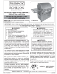
1
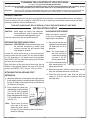
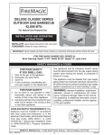
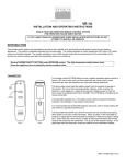
CUSTOM POST
CHARCOAL GRILLS
22 Series (In-ground and patio mount)
INSTALLATION AND OPERATING
INSTRUCTIONS
Patio mount
model shown
INSTALLER: Leave these instructions with consumer.
CONSUMER: Retain for future reference.
IMPORTANT: READ THESE INSTRUCTIONS CAREFULLY BEFORE STARTING INSTALLATION OR USE.
SAFETY WARNINGS & CODES
WARNING
WARNING
Improper installation, adjustment, alteration,
service, or maintenance can cause injury or
property damage. Refer to this manual. For
assistance or additional information, consult a
qualified professional installer, or service agency.
Do not store or use gasoline or other flammable
vapors and liquids, including propane cylinders,
in the vicinity of this or any other appliance.
CODE REQUIREMENTS:
This grill must be installed in accordance with local codes and ordinances.
WARNING: All surfaces of the charcoal unit become HOT during use. Exercise caution when using
this unit, especially when adding charcoal or cranking the charcoal pan up or down.
The grill serial identification number is located on the underside of the drip tray handle. It
is recommended that the drip tray first be removed and cleaned / emptied of its contents,
then turned over to view.
TABLE OF CONTENTS
2
3
3
3
3
3
3
4
4
5
6
7
8
REPLACEMENT PARTS LIST
PLANNING THE LOCATION OF YOU POST GRILL
EXHAUST REMOVAL
INSTALLATION & SETUP
SECURING THE PATIO MOUNT GRILL
ATTACHING THE IN-GROUND POST EXTENSION
IN-GROUND PROCEDURE
RIGID SHELF ASSEMBLY
OPERATION
ACCESSORIES
NOTES PAGE
CARE & CLEANING
WARRANTY
Robert H. Peterson Co. • 14724 East Proctor Avenue • City of Industry, CA 91746
REV 4 - 1405300810
1
L-C2-214
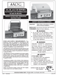
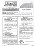
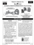
REPLACEMENT PARTS LIST
Item Description
Part No.
Qty.
1.
Stainess steel cooking grids (set of 2)
3542-S-2
2.
Custom, smoking oven Lift-A-Fire (LAF)
23756-C
1
3.
Shelf rigid
24330-017
2
4.
Face, Custom LAF assembly
3137-06
1
5.
Drip tray assembly
3081
1
6.
Patio base w/hardware
24330-31
1
or
In-ground base w/hardware
24330-32
1
7.
Patio mount hardware kit
24330-25
1
8.
Charcoal pan
3302-S
1
9.
Warming rack
3672C
1
3900-40
1
11. Crank
23302
1
12. Charcoal Shield
3305
1
10. Handle only
1
IMPORTANT
This Fire Magic® grill is
pre-assembled and tested
at the factory.
The plastic straps that
secure the oven to the
grill unit must be removed
and discarded prior to
lighting.
1
Replacement parts can be ordered
from your local Fire Magic® dealer.
9
2
12
3
8
Fig. 2-1
3
4
5
6
10
11
7
(Drip tray heat shield)
(Drip tray)
REV 4 - 1405300810
2
L-C2-214
PLANNING THE LOCATION OF YOU POST GRILL
This grill is designed FOR OUTDOOR USE ONLY.
DO NOT use this unit under unprotected flammable surfaces. DO NOT use this appliance inside a building, garage,
or any other enclosed area. It must not be used in or on recreational vehicles or boats.
Important:
This unit is NOT insulated, and therefore during use it must be located with a minimum of 18" of side and back
clearance from unprotected combustible materials such as wood, plastic, or stucco with wood framing.
EXHAUST REMOVAL
If installed under a patio roof, the grill area should be fully covered by a non-combustible chimney and exhaust
hood. An exhaust fan with a rating of 1,000 CFM or more is necessary to efficiently remove smoke and other
cooking by-products from the covered area.
THIS UNIT SHOULD NOT BE LOCATED IN A FULLY ENCLOSED AREA OF ANY KIND.
INSTALLATION & SETUP
CAUTION: Metal edges are sharp; use adequate
hand protection such as gloves when
assembling and configuring the grill.
IN-GROUND PROCEDURE
Read instructions carefully
all the way through before
beginning the installation.
Carefully unpack your grill and check the parts.
1. Dig a hole for the post and
extension approximately
18" deep and 10-12" in
diameter.
SECURING THE PATIO MOUNT GRILL
Important: BEFORE USE, the patio mount base must
be securely fastened to a stable, level
surface to ensure the grill remains fixed
and upright at all times.
Note: The actual depth of
the hole should be
such that the cooking
surface is 34-45"
above ground level.
Locate the patio mount base in the planned grill
location and mark the 4 holes. Drill the marked holes
to a 1/2" diameter x 1 1/2" depth. Insert the lag shields
(see PARTS LIST) into the holes, being sure that they
are flush with the ground.
Fig. 3-2
Post
(back view)
Ground level
Concrete level
2. Pour the concrete into the
hole approximately 3-5"
below ground level.
Align the holes on the patio mount base over the lag
shields in the ground. Secure the base with the lag
screws (see PARTS LIST) using a 7/16" nut driver.
3. While the concrete is still wet, carefully lower the grill
post and attached extension into the hole.
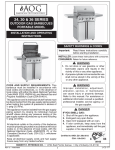
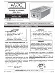
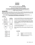
ATTACHING THE IN-GROUND POST
EXTENSION
4. Orient the grill per plan, then level the grill and
support it so that it remains in position while the
concrete dries.
1. Attach the extension to the bottom of the grill post so
that the open portion is toward the back of the grill and
the five (5) holes in the extension line up with the five
(5) weld-nuts in the post.
2. From outside the joined post
and extension, insert one of the
1/4 x 20-5/8" bolts (supplied)
into each of the five (5) bolt
holes and tighten each using a
7/16" socket driver or wrench
(see Fig. 3-1).
Weld-nut
To grill
Bolts
Note: There is one (1) hole on
each side of the post,
Fig. 3-1
except the back, which
has two (2) holes located on either side of the
extension opening.
REV 4 - 1405300810
3
L-C2-214
INSTALLATION & SETUP (cont.)
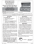
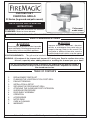
ALIGN CRANK HANDLE
WITH NUT & SCREW IN
ASSEMBLY
Crank
1. Locate the crank handle (Fig. 4-1) packed inside the grill
enclosure.
2. Open the door in the front panel as shown in Fig. 4-1 and
insert the threaded end into the crank handle through the
hole on the right of the grill face and into the nut on the frame
as shown.
3. Center the crank on the nut and begin cranking in a clockwise
direction until the threads have properly caught hold.
4. Close the door in the front panel and continue cranking until
the lifter begins to move upward inside the grill.
Note: The access door must be closed for the crank to raise
the lifter to the highest position.
5. Place both cooking grids with cut-outs toward the front as
shown in Fig. 4-2.
Door
Fig. 4-1
Fig. 4-2
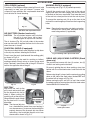
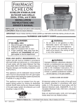
RIGID SHELF ASSEMBLY
This grill comes with two (2) rigid shelves that must Note: You may lift the edge of the shelf upward
be attached. These can be attached using the four
to gain better access during much of the
(4) support screws provided and a long Phillips-head
tightening of this screw.
screwdriver.
4. Finally, insert the bottom screws on the left and
1. Hold the shelf inverted so that one of the corner
right side of the shelf and securely tighten all
holes in the shelf lines up with the appropriate
screws.
upper screw hole in the grill.
Detaching is the reverse process of above.
2. Insert the screw (but do not tighten all the way)
so that the shelf can be easily rotated around
Shelf support screws
the first screw.
3. Line up the second corner hole in the shelf with
the remaining upper screw hole in the grill. Insert
a screw and tighten.
Fig. 4-3 View from under right shelf
OPERATION
Simple to use, this elegant stainless-steel charcoal
grill has the added benefit of an adjustable charcoal
pan to allow you to change the height of the charcoal
while cooking, and gives you the ability to add fuel
without having to remove the cooking grids. This
enables the outdoor chef to be in complete control
of the cooking heat at the grilling surface.
2. Follow the instructions supplied with your
charcoal/fuel for lighting.
3. Use the access door to add or spread out your
coals while cooking.
CAUTION: Use long-handled insulated barbecuing
tools to prevent burns from hot metal
or coals.
4. Turning the crank handle raises or lowers the
pan to increase or decrease the grilling heat as
you desire.
USING YOUR CHARCOAL GRILL
1. Remove the cooking grids and pile your charcoal
on the charcoal pan(s). Avoid spillage.
WARNING: When adding charcoal, spread it
across the charcoal pan evenly and DO
NOT exceed a height of 1" above the
charcoal pan.
Excessive amounts of charcoal may
cause over heating and damage to
your grill.
REV 4 - 1405300810
4
L-C2-214
ACCESSORIES
GRILL BRUSH (optional)
WARMING RACK (if equipped)
Purchase a Fire Magic® stainless-steel grill brush (sold
separately) to keep your grill cleaner. It comes with
scraper for large particles and a replaceable head with
brass bristles for overall cleaning.
The warming rack (Fig. 5-2) is packed separately.
To install the warming rack, lift the front of the rack up
slightly and insert the rack hangers into the two holes
in the back of the inner oven hood. Then lower the front
of the rack into a level position to lock the rack in place.
To remove the warming rack, lift up on the front of the
rack until the rack hangers pull free from their supporting
holes.
Fig. 5-1
Note: Removing the warming rack before using the
rotisserie will leave more clearance for the
meat being cooked. (if applicable)
Grill brush with replacement head
AIR SHUTTERS (Smoker hoods only)
CAUTION: The air shutters become very hot when
the grill is in use. Use a tool or heatinsulated glove to adjust the air shutters.
The air shutters (Fig. 5-3) on both sides of the smoker
oven can be used to regulate the flow of air to the coals
when the oven is closed.
CHARCOAL SHIELD (if equipped)
The charcoal shield allows meat drippings to drip down
to the drip tray without affecting the charcoal.
Fig. 5-2 Warming rack in place inside oven
Place it over the coals (and beneath the cooking grids)
as shown in Fig. 5-4.
USING AND (UN)LOCKING CASTERS (Stand
alone only)
The shield may also be used for smoking or indirect
cooking methods. Simply set up as shown (using wood
chips if desired), toward one side of the grill. Place the
food on the opposite side of the grill.
The portable cart comes with four (4) casters, two (2)
of which are locking and articulated.
For ease in guiding the cart when pushing, steer from
behind with the articulated casters and lead with the
others.
Before using the grill, always lock the casters by pushing
down on the side of the steel rocker labeled OFF until
the wheel will no longer roll (Fig. 5-6).
Fig. 5-3
Before moving the grill, wait for it to cool, then unlock
the wheels again by pressing the side of the steel rocker
labeled ON until the wheel rolls.
Fig. 5-4
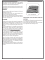
DRIP TRAY
After each use, wait for the
grill to cool and carefully pull
out the charcoal drip tray to
check it. When nearing full,
carefully pull out the drip tray,
lifting with both hands to keep
the tray level until it is safely
discarded.
DIMPLES MUST
FACE DOWNWARD
Fig. 5-5
Note: The charcoal drip tray
has a heatshield to protect from over heating. It
may be neccessary to remove the heatshield to
properly clean out the charcoal drip tray. When
reinstalling, the heatshield dimples must face
downward as shown in Fig. 5-5.
Fig. 5-6
Locking the casters
5
NOTES PAGE
6
CARE & CLEANING
APPLIANCE MUST BE COMPLETELY COOL WHEN
CLEANING. DO NOT SPRAY ANY CLEANER OR
LIQUIDS ON THE APPLIANCE WHEN HOT.
The appliance must be cleaned as often as once a month
(depending on use) to prevent grease build-up and other
food deposits.
Wipe wit
h grain
INTERIOR
Empty the charcoal drip tray and screen of all ash and
drippings after each use.
Clean the charcoal screen, pan, and the interior of the
grill with a water and mild soap solution.
Fig. 7-1 - Wipe with grain
The inside of the appliance may be cleaned periodically
with oven cleaner if desired. Follow the oven cleaner
PROTECTING YOUR APPLIANCE FROM THE
instructions for proper use.
WEATHER
EXTERIOR
An optional cover will protect your appliance when not
Stainless steel surfaces when exposed to temperatures in use. (Allow to cool before covering.)
produced by the grilling process will change color. The
stainless steel will change color from silver to brown Please specify the model number and serial number
and blue. This can be removed by using stainless steel of your appliance when ordering a cover.
cleaner.
Clean your appliance by first using grill cleaner to remove
grease and dirt. Always wipe with the grain (See Fig.
7-1). Next, use stainless steel cleaner to restore the
stainless steel color (Note: not for mirror finish). Finish
by wiping your appliance down using polish wipes.
If your appliance is installed in a seaside (salt air) or
poolside (chlorine) location, it will be more susceptible
to corrosion and must be maintained/cleaned more
frequently. Do not store chemicals (such as chlorine or
fertilizer) near your stainless steel appliance.
Due to the nature of stainless steel, surface iron oxide
deposits may appear. Do not be alarmed – these deposits
are removable with stainless steel cleaner through prompt
and periodic maintenance. If not attended to promptly,
permanent pitting may occur.
By following these recommendations, you will enjoy the
beauty and convenience of your appliance for many years
to come.
7
WARRANTY
PETERSON FIRE MAGIC GRILLS AND ACCESSORIES
LIMITED WARRANTY
Robert H. Peterson Co. ("RHP") warrants your Fire Magic® grill to be free from defects in material and workmanship.
Fire Magic® cast stainless-steel burners, stainless-steel rod cooking grids, and stainless-steel housings are warranted for as long as you own
your Fire Magic® grill -- LIFETIME. (Except as noted below.)
Fire Magic Choice stainless steel tubular burners are warranted for TWENTY (20) YEARS.
Fire Magic® cast brass burners, brass valves, inner liners, manifold assemblies, and backburner assemblies (except ignition parts) are
warranted for FIFTEEN (15) YEARS.
Fire Magic® Electric Grills, including stainless steel grid, and housings are warranted for TEN (10) YEARS.
Fire Magic® Infra-red burners, flavor grids, Charcoal stainless steel grills, and Smokers are warranted for FIVE (5) YEARS; except for the
charcoal pan, charcoal grid, wood pellet screen, thermometer, and ash tray; which are warranted for ONE (1) YEAR.
Fire Magic® sideburners and all other Fire Magic® grill components (except ignition and electronic parts) are warranted for THREE (3)
YEARS.
Fire Magic® ignition systems (excluding batteries), electronic components (including lights and thermometers), and grill accessories are
warranted for ONE (1) YEAR.
A COPY OF YOUR SALES SLIP FOR PROOF OF PURCHASE IS REQUIRED
This warranty applies to the original purchaser for products which are installed in the United States or Canada and which are operated and maintained
as intended for single family residential usage. This warranty is valid only with proof of purchase, shall commence on the date of purchase, and shall
terminate (both as to original and any replacement products) on the anniversary date of the original purchase of the product stated on the above schedules.
This warranty covers defects in material and workmanship. This warranty does not cover parts which become defective as a result of negligence, misuse,
use not in compliance with the Owner’s Manual/Installation Instructions, accidental damage, improper handling, improper storage, improper installation,
lack of required routine maintenance (as specified in the Owner’s Manual/Installation Instructions), electrical damage, local gas impurities or failure to
protect against combustibles. Product must be installed (and gas must be connected) as specified in the Owner’s Manual/Installation Instructions by
a qualified professional installer. Modifications to products which are not specifically authorized will void this warranty. Accessories, parts, valves,
remotes, etc. when used must be Peterson products or this warranty is void. Warrantied items will be repaired or replaced at Peterson’s sole discretion.
This warranty does not apply to rust, corrosion, oxidation, or discoloration unless the affected part becomes inoperable.
This warranty does not cover labor or labor related charges, except as provided by separate specific written programs from the Peterson Co. All repair
work must be performed by a qualified professional service person and requires prior approval of Peterson.
Peterson may require the defective product or part to be returned to the factory to determine the cause of failure. Peterson will pay freight charges if
the product or part is determined to be defective. This warranty does not cover breakage in shipment from our (Independent) distributor to its customer
if the damage is determined to have occurred during that shipment.
This warranty specifically excludes liability for indirect, incidental, or consequential damages. Some states and provinces do not allow the exclusion
or limitation of incidental or consequential damages, so the above exclusion may not apply to you. This warranty gives you specified legal rights, and
you may have other rights that vary from state to state or province.
For additional information regarding this warranty, or to place a warranty claim, contact the R. H. Peterson dealer where the product was purchased.
TO REGISTER YOUR PRODUCT ONLINE GO TO: WWW.RHPETERSON.COM,
AND CLICK ON PRODUCT REGISTRATION. THANK YOU FOR YOUR PURCHASE.
Quality Check
Date:_________________
Model#:
_____________________
Serial#:
________________________
Inspector:
_____________________
Workmanship Inspection:
Robert H. Peterson Co. • 14724 East Proctor Avenue • City of Industry, CA 91746
8
___________