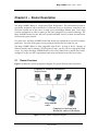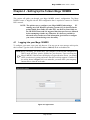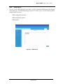
1
Mega 100WR2 ADSL2+ Router -
Manual
Table of Contents
Preliminary Pages
Page
Table of Contents .................................................................................................................1
List of Ilustrations ................................................................................................................4
Chapter 1 - About this Manual ..........................................................................................9
1.1
Introduction ......................................................................................9
1.2
Scope and Purpose............................................................................9
1.3
Targeted Audience............................................................................9
1.4
Manual Organization ........................................................................9
Chapter 2 – Router Description ......................................................................................10
2.1
Router Overview ............................................................................10
Chapter 3 - Your Router At A Glance.............................................................................11
3.1
Ports and Buttons (See 3.2.2) .........................................................11
3.2
Mega 100WR2 Overview...............................................................12
3.2.1
Front Panel Indicators.....................................................................12
3.2.2
Back Panel ......................................................................................13
Chapter 4 - Setting Up the Telkom Mega 100WR2........................................................14
4.1
Logging into your Mega 100WR2 .................................................14
4.1.2.
Subsequent logins...........................................................................18
4.2
Quick Start......................................................................................19
4.3
LAN / DHCP Configuration...........................................................19
4.4
Diagnostic Test...............................................................................21
4.4.1
Ping Test.........................................................................................22
4.4.2
Full Modem Test ............................................................................23
4.5
Advanced........................................................................................25
4.5.1
WAN Connection ...........................................................................25
4.5.2
New Connection .............................................................................25
4.5.3
ADSL Modulation ..........................................................................26
4.5.4
Quickstart .......................................................................................27
4.5.5
LAN Configuration ........................................................................28
4.5.6
LAN Clients....................................................................................29
4.5.7
Ethernet Switch Configuration .......................................................30
4.5.8
Application (UPnP) ........................................................................30
4.5.9
SNTP ..............................................................................................31
Page 1 of 81
Mega 100WR2 ADSL2+ Router -
Manual
4.5.10
SNMP .............................................................................................32
4.5.11
IGMP Proxy....................................................................................33
4.5.12
TR-068 WAN Access.....................................................................34
4.5.13
TR-069............................................................................................35
4.5.14
NAT services ..................................................................................36
4.5.15
DNS Proxy......................................................................................37
4.5.16
Dynamic DNS Client (DDNS) .......................................................37
4.5.17
Easy Connect Configuration...........................................................38
4.5.18
Port Triggering ...............................................................................39
4.5.19
Port Forwarding..............................................................................40
4.5.20
Bridge Filters ..................................................................................41
4.5.21
Web Access Control .......................................................................42
Enable Web Access Control (WAN-Side) .....................................42
4.5.22
SSH Access control ........................................................................43
Enable SSH Access Control (WAN-Side) .....................................43
4.5.23
QoS .................................................................................................44
4.5.24
Egress .............................................................................................45
No Egress Mode .............................................................................45
Egress Layer 2 Configuration.........................................................46
Egress Layer 3 Configuration.........................................................47
4.5.25
Ingress.............................................................................................48
Ingress Untrusted Mode .................................................................48
Ingress Layer 2 Configuration........................................................49
Ingress Layer 3 Configuration........................................................51
Ingress Static Configuration ...........................................................53
4.5.26
QoS Shaper Configuration .............................................................54
4.5.27
Policy Routing Configuration.........................................................58
4.5.28
Static Routing .................................................................................60
4.5.29
Dynamic Routing............................................................................62
4.5.30
Routing Table .................................................................................63
4.5.31
System Password ............................................................................63
4.5.32
Firmware Upgrade..........................................................................64
4.5.33
Restore to Default...........................................................................64
4.6
Wireless ..........................................................................................65
4.6.1
Wireless Setup ................................................................................65
4.6.2
Wireless Configuration...................................................................66
Page 2 of 81
Mega 100WR2 ADSL2+ Router -
Manual
4.6.3
Multiple SSID.................................................................................67
4.6.4
Wireless Security............................................................................67
4.6.5
4.6.4.1
WEP.............................................................................68
4.6.4.2
802.1x ..........................................................................68
4.6.4.3
WPA ............................................................................69
Wireless Management ....................................................................70
4.6.5.1
Access List...................................................................70
4.6.5.2
Associated Stations......................................................70
4.6.6
Wireless Distribution system..........................................................71
4.7
Security...........................................................................................72
4.7.1
IP Filters .........................................................................................73
4.7.2
LAN Isolation.................................................................................73
4.7.3
URL Filters.....................................................................................74
4.8
Status ..............................................................................................75
4.8.1
Connection Status...........................................................................75
4.8.2
System Log.....................................................................................76
4.8.3
Remote Log Settings ......................................................................76
4.8.4
Network Statistics...........................................................................77
4.8.5
DHCP Clients .................................................................................78
4.8.6
QoS status.......................................................................................78
4.8.7
Modem Status.................................................................................79
4.8.8
Product Information........................................................................79
4.8.9
WDS Report ...................................................................................80
4.9
Help ................................................................................................81
Page 3 of 81
Mega 100WR2 ADSL2+ Router -
Manual
List of Ilustrations
Figure
Page
Figure 2-1: Router system configuration diagram ...............................................................10
Figure 3-1 : Front Panel Indicators ......................................................................................12
Figure 3-2: Back Panel Indicators........................................................................................13
Figure 4-1: login screen........................................................................................................14
Figure 4-2: Setup Page .........................................................................................................15
Figure 4-3 : Internet Login Account Setting ........................................................................15
Figure 4-4: Wireless LAN Configuration ............................................................................16
Figure 4-5:System Password................................................................................................16
Figure 4-6: Summery ...........................................................................................................17
Figure 4-7: Trying to connect to ISP....................................................................................18
Figure 4-8: Basic Home .......................................................................................................18
Figure 4-9: Quick Start Page................................................................................................19
Figure 4-10: LAN / DHCP Configuration............................................................................20
Figure 4-11: Diagnostics Test Screen ..................................................................................21
Figure 4-12: Diagnostics Test Result Screen .......................................................................22
Figure 4-13: Ping Test Screen ..............................................................................................23
Figure 4-14: Modem Test.....................................................................................................24
Figure 4-15: Advanced Screen .............................................................................................25
Figure 4-16: New Connection (PPPoE Connection Setup)..................................................26
Figure 4-17: ADSL Modulation (Modem Setup).................................................................26
Figure 4-18: Quickstart (PPPoE Connection Setup) ............................................................28
Figure 4-19: LAN Configuration .........................................................................................29
Figure 4-20: LAN Clients ....................................................................................................29
Figure 4-21: Ethernet Switch Configuration ........................................................................30
Figure 4-22: UPnP................................................................................................................31
Page 4 of 81
Mega 100WR2 ADSL2+ Router -
Manual
Figure 4-23: SNTP ...............................................................................................................32
Figure 4-24: SNMP Management ........................................................................................32
Figure 4-25: IGMP Proxy ....................................................................................................33
Figure 4-26: TR-068 WAN Access......................................................................................34
Figure 4-27: TR-069.............................................................................................................36
Figure 4-28: NAT Services ..................................................................................................36
Figure 4-29: DNS Proxy ......................................................................................................37
Figure 4-30: Dynamic DNS Client.......................................................................................38
Figure 4-31: Easy Connect Configuration ...........................................................................39
Figure 4-32: Port Triggering ................................................................................................39
Figure 4-33: Port Forwarding...............................................................................................41
Figure 4-34: Bridge Filters...................................................................................................41
Figure 4-35: Web Access Control........................................................................................42
Figure 4-36 : SSH Access Control .......................................................................................43
Figure 4-37: No Egress ........................................................................................................45
Figure 4-38: Egress Layer 2 .................................................................................................46
Figure 4-39: Egress Layer 3 .................................................................................................47
Figure 4-40: Ingress Untrusted Mode ..................................................................................48
Figure 4-41: Ingress Layer 2 Configuration.........................................................................49
Figure 4-42: Ingress Layer 3 Configuration.........................................................................51
Figure 4-43: Ingress Static Configuration ............................................................................53
Figure 4-44: QoS Shaper Configuration ..............................................................................54
Figure 4-45: HTB Queue Discipline enabled.......................................................................55
Figure 4-46: Low Latency Queue Discipline enabled .........................................................56
Figure 4-47: PRIOWRR enabled .........................................................................................57
Figure 4-48: Policy Routing Configuration .........................................................................58
Figure 4-49: Static Routing ..................................................................................................61
Figure 4-50: Dynamic Routing ............................................................................................62
Page 5 of 81
Mega 100WR2 ADSL2+ Router -
Manual
Figure 4-51: Routing Table ..................................................................................................63
Figure 4-52: System Password.............................................................................................63
Figure 4-53: Firmware Upgrade...........................................................................................64
Figure 4-54: Restore to Default prompt ...............................................................................64
Figure 4-55: Wireless Setup Page ........................................................................................65
Figure 4-56: Wireless Configuration Page...........................................................................66
Figure 4-57: Multiple SSID..................................................................................................67
Figure 4-58 : Wireless Security............................................................................................67
Figure 4-59: Wireless Security – WEP ................................................................................68
Figure 4-60: Wireless Security – 802.1x..............................................................................69
Figure 4-61: Wireless Security - WPA ................................................................................69
Figure 4-62: Wireless Management .....................................................................................70
Figure 4-63: WDS ................................................................................................................71
Figure 4-64: Security............................................................................................................72
Figure 4-65: IP Filters ..........................................................................................................73
Figure 4-66: LAN Isolation..................................................................................................74
Figure 4-67: URL Filters......................................................................................................74
Figure 4-68: Status ...............................................................................................................75
Figure 4-69: Connection Status............................................................................................76
Figure 4-70: System Log......................................................................................................76
Figure 4-71: Remote Log Settings .......................................................................................77
Figure 4-72: Network Statistics............................................................................................77
Figure 4-73: DHCP Clients ..................................................................................................78
Figure 4-74: QoS status........................................................................................................78
Figure 4-75: Modem Status..................................................................................................79
Figure 4-76: Product Information ........................................................................................79
Figure 4-77: WDS Report ....................................................................................................80
Figure 4-78: Help Screen .....................................................................................................81
Page 6 of 81
Mega 100WR2 ADSL2+ Router -
Manual
Declaration Of Conformity
Marking equipment with the above symbol indicates compliance with the Essential
Requirements of the R&TTE Directive of the European Union (1999/5/EC). This equipment
meets the following conformance standards:
EN300 328, EN301 489-17, EN60950
Radio Frequency Interference Warnings & Instructions
This equipment has been tested and found to comply with the limits for a Class B digital device,
pursuant to Part 15 of the FCC Rules. These limits are designed to provide reasonable protection
against harmful interference in a residential installation. This equipment uses and can radiate
radio frequency energy and, if not installed and used in accordance with the instructions, may
cause harmful interference to radio communications. However, there is no guarantee that
interference will not occur in a particular installation. If this equipment does cause harmful
interference to radio or television reception, which can be determined by turning the equipment
off and on, the user is encouraged to try to correct the interference by one or more of the
following methods:
Reorient or relocate the receiving antenna.
Increase the separation between the equipment and the receiver.
Connect the equipment into an electrical outlet on a circuit different from that
which the radio receiver is connected.
Consult the dealer or an experienced radio/TV technician for help.
Modifications made to the product, unless expressly approved by the party responsible, could
void the user’s right to operate the equipment.
RF Exposure
The Wi-Fi card used in this router has been tested and complies with FCC RF Exposure (SAR)
limits in typical laptop computer configurations meaning that it can be used in desktop or laptop
computers with side mounted PCMCIA slots, which can provide 1 cm separation distance from
the antenna to the body of the user or a nearby person, but use in thin laptop computers may need
special attention to maintain antenna spacing while operating This also means that it cannot be
used with handheld PDAs (Personal Digital Assistants). Use in other configurations may not
ensure compliance with FCC RF exposure guidelines. This router and its antenna must not be
co-located or operate in conjunction with another antenna or transmitter.
Page 7 of 81
Mega 100WR2 ADSL2+ Router -
Manual
Safety Summary Messages
WARNING
HIGH VOLTAGE
is used in the equipment. Make sure equipment is properly grounded
BEFORE opening. Failure to observe safety precautions may result in electric
shock to user.
CAUTION
Check voltages before connecting equipment to power supplies. Wrong
voltages applied may result in damage to equipment.
Page 8 of 81
Mega 100WR2 ADSL2+ Router -
Manual
Chapter 1 - About this Manual
1.1
Introduction
Thank you for Purchasing the Telkom Mega 100WR2 Router. This manual contains all the
information that you should need to operate your router. Should you wish to set your router up in
the shortest possible time, then please follow the printed Quick Start Guide that is included with
you router package. The Quick Start Guide contains sufficient information to guide you through
the basic configuration of your router. For more complicated configurations, please read the Easy
Start guide that is included on the product CD. In both cases, we suggest that you still read the
Manual at some stage, as this will give you more insight into the advanced functions of your
router and enable you to get the best use out of your router.
1.2
Scope and Purpose
This manual provides the following:
An overview of the Telkom Mega 100WR2 system configuration and connectivity;
General description and specifications of the Telkom Mega 100WR2 system components;
Operating instructions of the Telkom Mega 100WR2 router system;
1.3
Targeted Audience
This manual is designed and developed for the operators and users who are required to operate
and perform first-level maintenance of the Mega 100WR2 Router. It assumes the reader of this
manual has basic knowledge and experience in operating similar modem configuration and
computer systems equipment.
1.4
Manual Organization
The manual is divided into the following chapters:
Chapter 1 – About this Manual; This chapter provides an introduction to the manual’s scope and
purpose, targeted audience and contents organisation.
Chapter 2 – Router Description; This chapter provides the system description and system
configuration diagram of ADSL Router connections.
Chapter 3 – Your Router At A Glance; This chapter provides an overview of Ports, LED’s, Front
and Back indicators of the Mega 100WR2 Router.
Chapter 4 – Setting Up the Telkom Mega 100WR2 Router; This chapter provides description of
all function within the Web User Interface.
Page 9 of 81
Mega 100WR2 ADSL2+ Router -
Manual
Chapter 2 – Router Description
The Mega 100WR2 Router is a high-speed WAN bridge/router. This full-featured product is
specifically designed to allow maximum of 4 Ethernet devices to be directly connected to the
local area network side of the router, via high speed 10/100 Mbps Ethernet ports. Users using
wireless workstations are able to connect to the router using 802.11g wireless technology. The
Mega 100WR2 Router has also full NAT firewall and DMZ services to block unwanted users
from accessing your network.
For game users, the Mega 100WR2 Router had already pre-configured for several low latency
game ports. Just click on the game you are playing on-line and the rest is done for you.
The Mega 100WR2 Router is fully compatible with all PCs: As long as the PC supports an
Ethernet interface and is running a TCP/IP protocol stack, your PC can have high-speed WAN
access. So, plug in the Mega 100WR2 Router (refer to Easy Start Guide or Quick Start Guide),
configure it (as per your ISP’s requirements) and enjoy fast Internet access like never before.
2.1
Router Overview
Figure 2-1 shows the system configuration diagram of a typical Wireless router connection.
Computers or Notebooks with Ethernet
Network Cards.
Mega 100WR2
router
Computers or Notebooks with
Wireless PC cards or USB Clients.
Figure 2-1: Router system configuration diagram
Page 10 of 81
Mega 100WR2 ADSL2+ Router -
Manual
Chapter 3 - Your Router At A Glance
The Mega 100WR2 has the following features.
3.1
Ports and Buttons (See 3.2.2)
Reset and Restore to Factory Defaults: The “restore to factory defaults” feature will set the
Mega 100WR2 Router to its factory default configuration. You may need to return your router to
its factory defaults if the configuration is changed and you lose the ability to interface with the
router via the web interface, or following a software upgrade. To reset the Mega 100WR2 router,
simply press and hold the reset button (on the back panel) for about approximately 10 seconds.
The router will be reset to its factory defaults and after about 30 ~ 40 seconds the router will
become operational again.
LAN (Local Area Network) E1 to E4 port(s): These ports connect to Ethernet network
devices, such as a PCs, Hubs, Switches, or Routers. The ports are 10/100 Base-T AutoMDI/MDIX Ethernet jacks (RJ-45). (These ports allow either cross or straight cables to be used.)
Power: This is where you connect the power. Make sure you observe the proper power
requirements. Use only the supplied Power Supply (LPU) to prevent incorrect operation/damage
to your router.
USB (Universal Serial Bus): This port connects to a PC’s USB port. The Mega 100WR2
router’s USB port only supports Windows based PCs, via an RNDIS driver (Included with the
software on the supplied CD).
DSL port: This is the WAN interface that connects directly to your ADSL enabled phone line.
Page 11 of 81
Mega 100WR2 ADSL2+ Router -
3.2
3.2.1
Manual
Mega 100WR2 Overview
Front Panel Indicators
Figure 3-1 shows the front panel indicators of the Mega 100WR2 router.
4
1
2
3
6
5
Figure 3-1 : Front Panel Indicators
LED Name
Status & Meaning
1. Power
Lights up when power is supplied to the ADSL Router.
2. E1 - E4 (Ethernet)
Lights up when the Ethernet cable is properly connected
from your Router to an Ethernet device/card. Flickers
when the Router is transmitting/receiving data.
3. Wireless
Flickers when the Wireless LAN is operating.
4. USB
Lights up when the USB cable is properly connected
from your router to your PC’s USB port. Light is Off
when the USB cable is not (properly) connected.
5. DSL
Light is off when no ADSL enabled telephone line is
connected. Flickers when the ADSL Router is trying to
establish a connection with your ISP (Training). Lights
up when the ADSL connection is established.
6. Internet
Lights up when the PPP connection is established. Light
is off when there is no PPP connection.
Page 12 of 81
Mega 100WR2 ADSL2+ Router -
3.2.2
Manual
Back Panel
Figure 3-2 shows the back panel indicators of the Mega 100WR2 router.
7
4
E1
1
2
5
3
6
Figure 3-2: Back Panel Indicators
Label
Description
1. DSL
Connects to your ADSL enabled telephone line.
2. USB
Connects to your PC’s USB port, if required.
3. RESET
To reset the ADSL Router, simply press and hold the
reset button for at least 10 seconds (all customised
settings that you have saved will be lost and the router
will be returned to factory default settings ).
4. E1-E4
(ETHERNET)
The 10/100 Base-T Auto-MDI/MDIX Ethernet jacks
(RJ-45) connect to your PC’s Ethernet (Network) card or
an Ethernet Hub / Switch.
5. DC 9V
To connect to the Power Adapter (LPU) that comes with
your package.
6. POWER SWITCH
Push downwards to switch ON and press upwards to
switch OFF.
7. RF Antenna
2.4Ghz Wireless Antenna.
Page 13 of 81
Mega 100WR2 ADSL2+ Router -
Manual
Chapter 4 - Setting Up the Telkom Mega 100WR2
This section will guide you through your Mega 100WR2 router’s configuration. The Mega
100WR2 router is shipped with the PPP configuration that is required to connect to Telkom
ISP’s network.
NOTE: The quickest way to configure your Mega 100WR2 when using a
PC
running one of the Windows operating systems (OS), is described in the
printed Quick Start Guide (for other OSs’, use the Easy Start Guide on
the CD in PDF form) and it is suggested that these processes are followed
before attempting to make any connection. It is however possible for
advanced users to make use of the information given below to configure
your router, without having to use the utility.
4.1
Logging into your Mega 100WR2
To configure your router, open your web browser. You may get an error message at this point;
this is normal. Type the router’s default IP address (10.0.0.2) on the web address bar.
NOTE:Before continuing, you should have your computer’s network card configured for
DHCP mode and have proxies disabled on your browser. Upon accessing the
Mega 100WR2, if the browser still displays a login redirection screen, you should
check your browser's setting and ensure that the JavaScript support is enabled. If
the screen shown in Figure 4-1 is not attainable, you must delete your temporary
Internet files to clear the web cache.
Figure 4-1: login screen
Page 14 of 81
Mega 100WR2 ADSL2+ Router -
Manual
4.1.1. First Login
Upon entering the default IP address (10.0.0.2), if the user is logging for the first time
(and has not been setup using the setup utility), the user will be shown the “Setup” page
as shown in Figure 4-2. This setup routine is to ensure that the basic settings are entered
into the router before a user attempts to change any of the advanced settings. Please click
on Internet Login Account Setting
Figure 4-2: Setup Page
The page in Figure 4-3 will now be displayed. This page is for configuring the basic
settings of your account. Please do not change the Protocol, VPI and VCI information
unless requested by your ISP – The default values are those required to achieve
connectivity through Telkom ISP, but other ISP’s may require different values. This
setup utility continues as per Figure 4-3 till Figure 4-7 and more or less explains its self.
A few additional comments are given below:
Figure 4-3 : Internet Login Account Setting
Page 15 of 81
Mega 100WR2 ADSL2+ Router -
Manual
It’s a good idea to change your SSID – this is the name of your Wi-Fi port.
Figure 4-4: Wireless LAN Configuration
This setup process forces you to change the default Admin password for better security
Figure 4-5:System Password
Page 16 of 81
Mega 100WR2 ADSL2+ Router -
Manual
You should print out the summery page and keep it for future reference
Figure 4-6: Summery
If you complete this process, and the router is unable to connect to the Internet, and you are
unable to solve the problem, then it is a good idea perform a “Default Reset” on the
router, and rather use the Setup Utility on the supplied CD to set your unit up.
Page 17 of 81
Mega 100WR2 ADSL2+ Router -
Manual
Figure 4-7: Trying to connect to ISP
4.1.2. Subsequent logins
Those who have already configured their routers via the Utility or have previously
set the router up via the Web browser will be directed to the “Basic Home” page. See
Fig 4-8.
Figure 4-8: Basic Home
Page 18 of 81
Mega 100WR2 ADSL2+ Router -
4.2
Manual
Quick Start
If you wish to change your current configuration, click on the ‘Quick Start’ link. Figure 4-9
will appear. Your login information can be altered here is required.
Figure 4-9: Quick Start Page
4.3
LAN / DHCP Configuration
On one side of your Mega 100WR2 Router, are your Local Area Network (LAN) connections.
This is where you plug in your local computers to the ADSL Router. The physical connection to
the LAN side of your router is by means of the Wi-Fi, USB and Ethernet ports. The ADSL
Router is configured by default to automatically provide all of the PC's on your network with
Internet addresses (DHCP).
To enable or disable DHCP, click Basic, and select LAN Configuration. The Start IP Address is
where the DHCP server starts issuing IP addresses. This value should be greater than the ADSL
Router IP address value. For example if the ADSL Router IP address is 10.0.0.2 (default) than
the starting IP address should be 10.0.0.3 (or higher).
Page 19 of 81
Mega 100WR2 ADSL2+ Router -
Manual
The End IP Address is where the DHCP server stops issuing IP addresses. The ending address
cannot exceed a subnet limit of 254. Hence the max value for our default gateway is10.0.0.254.
If the DHCP server runs out of DHCP addresses, users will not get access to network resources.
If this happens you can increase the Ending IP address (to the limit of 254), or if you are not
using as many PCs as you have allowed DHCP numbers and you are still having the problem,
then you should reduce the lease time.
The Lease Time is the amount of time a network user will be allowed connection to the ADSL
Router with their current dynamic IP address. The amount of time is in units of minutes; the
default value is 3600 minutes (60 hours).
Note: If you change the start or end values, make sure the values are still within the same subnet
as the gateways IP address. In other words, if the gateways IP address is 10.0.0.2 (default) and
you change the DHCP start/end IP addresses to be 192.128.1.2/192.128.1.100, you will not be
able to communicate to the ADSL Router if your PC has DHCP enabled.
In addition to the DHCP server feature, the ADSL Router supports the DHCP relay function.
When the ADSL Router is configured as DHCP server, it assigns the IP addresses to the LAN
clients. When the ADSL Router is configured as DHCP relay, it is responsible for forwarding the
requests and responses - negotiating between the DHCP clients and the server.
When turning off the DHCP server and relay the network administrator must carefully configure
the IP address, Subnet Mask and DNS settings of every computer on your network. Do not
assign the same IP address to more than one computer and your router must be on the same
subnet as all the other computers. See Figure 4-10.
Figure 4-10: LAN / DHCP Configuration
Page 20 of 81
Mega 100WR2 ADSL2+ Router -
Manual
Note: This page is for the setup of LAN Group 1 only. If you have assigned
interfaces to different LAN Groups (see the advanced section) you will have to
view their details under “Advanced “, “LAN”,”LAN Configuration”
4.4
Diagnostic Test
Figure 4-11: Diagnostics Test Screen
Diagnostic Test is used for investigating whether the ADSL Router is properly connected to the
WAN Network. See Figure 4-11. This test may take a few seconds to complete. To perform the
test, select your connection from the list and press the Test button. Before running this test,
make sure you have a valid DSL link.
Page 21 of 81
Mega 100WR2 ADSL2+ Router -
Manual
Figure 4-12: Diagnostics Test Result Screen
After running the Diagnostic Test, the screen will indicate which tests pass or fail. See Figure 412.
4.4.1
Ping Test
Once you have your router configured, ensure you can ping the network. Type the target
address that you want to ping. If your PC is connected to the ADSL Router via the
default DHCP configuration, you should be able to ping the network address 10.0.0.2. If
your ISP has provided their server address, try to ping the address. If the pings for both
the WAN and the LAN sides are complete and you have the proper protocols configured,
you should be able to surf the Internet. By default when you select ping test, the Mega
100WR2 will ping 3 times. The router shown in Figure 4-13 passes a Ping test; this
basically means that the TCP/IP protocol is configured correctly. If the first Ping test
does not pass, the TCP/IP protocol is not loaded for some reason; you should restart your
router.
Page 22 of 81
Mega 100WR2 ADSL2+ Router -
Manual
Figure 4-13: Ping Test Screen
4.4.2
Full Modem Test
This test can be used to check whether the modem section of your router is properly
connected to the Network. This screen is accessed by first running a diagnostic test.
Select the type of your connection from the list and press the ‘Test’ button. Some ISPs do
not support this type of testing, so if the test fails, please consult your ISP to see which
form of test they support (If any) See Figure 4-14.
Page 23 of 81
Mega 100WR2 ADSL2+ Router -
Figure 4-14: Modem Test
Page 24 of 81
Manual
Mega 100WR2 ADSL2+ Router -
4.5
Manual
Advanced
This mode is catered for advance users, a brief explanation of the links are listed as shown
below. See Figure 4-15.
Figure 4-15: Advanced Screen
4.5.1
WAN Connection
The Wide Area Network (WAN) connection exists on the “other” side of the Router, also
referred to as a broadband connection. This WAN connection configuration is different
for each ISP. Your Mega 100WR2 is set by default to connect to the Telkom ISP and
should work as it is (once you have entered username and password information). Should
you wish to use this router to connect to any other ISP, you may need to change the
relevant configuration data.
4.5.2
New Connection
A new connection is a virtual connection. Under normal conditions, you will require only
one virtual connection. Your Mega 100WR2 Router, can however, support up to 8
different (unique) virtual connections. If you have multiple different virtual connections,
you may need to utilize the static and dynamic routing capabilities of the modem to pass
data correctly. Your Router is supplied with its first connection (quickstart) preconfigured (described below) .You may add up to 7 more, and may change the quickstart
connection if required.
Page 25 of 81
Mega 100WR2 ADSL2+ Router -
Manual
Figure 4-16: New Connection (PPPoE Connection Setup)
4.5.3
ADSL Modulation
To configure the DSL modulation type, Click WAN, ADSL Modulation. This will bring
up the modem setup screen (Figure 4-17). Tick the modes that you would like the
modem to be able to use. You are able to specify a particular type of modulation (Should
your ISP support only one particular type) by selecting only 1 option or you can select
many options and let the router detect which to use. In most cases, this screen should not
be modified.
Figure 4-17: ADSL Modulation (Modem Setup)
Page 26 of 81
Mega 100WR2 ADSL2+ Router -
4.5.4
Manual
Quickstart
PPPoE is also known as RFC 2516. It is a method of encapsulating PPP packets over
Ethernet. PPP or Point-to-Point protocol is a method of establishing a network
connection/session between network hosts. It provides a mechanism of authenticating
users.
To configure the router for PPPoE, click on Advanced. Under WAN, select New
Connection. The default PPPoE connection setup is displayed. At the Type field select
PPPoE and the PPPoE connection setup page is displayed. Give your PPPoE connection a
unique name; the name must not have spaces and cannot begin with numbers. In this case
the unique name is called “quickstart”. Select the encapsulation type (LLC or VC); if you
are connecting to the Telkom ADSL network, then use LLC. Select the VPI and VCI
settings use 8 and 35 for the Telkom network. Also select the quality of service (QoS);
leave the default value if you are unsure. See Figure 4-18
Following is a description of the different options:
1. Username: The username for the PPPoE access; this is provided by
Telkom or your ISP.
2. Password: The password for the PPPoE access; this is provided by
Telkom or your ISP.
3. On-Demand: Enables on-demand mode. The connection will
disconnect if no activity is detected after the specified idle timeout
value.
4. Idle Timeout: Specifies that PPPoE connection should disconnect if
the link has no activity detected for n seconds. This field is used in
conjunction with the On-Demand feature. To ensure that the link is
always active, enter a 0 in this field.
5. Keep Alive: When on-demand option is not enable, this value specifies
the time to wait without being connected to your ISP before
terminating the connection. To ensure that the link is always active,
enter a 0 in this field.
6. Enforce MTU: Check this box if you experience problems accessing
the Internet over a PPPoE connection. This feature will force all TCP
traffic to conform with PPP MTU by changing TCP Maximum
Segment Size to PPP MTU.
Page 27 of 81
Mega 100WR2 ADSL2+ Router -
Manual
Figure 4-18: Quickstart (PPPoE Connection Setup)
4.5.5
LAN Configuration
You can change the Mega 100WR2 Router’s IP address by clicking LAN, and then LAN
Configuration. Select the options from LAN group 1 and click Configure.
Your router’s default IP address and subnet mask are 10.0.0.2/255.255.255.0; this subnet
mask will allow the ADSL Router to support 254 users. If you want to support a larger
number of users you can change the subnet mask; but remember that the DHCP server is
defaulted to only give out 255 IP addresses. Further remember that if you change your
gateways’ IP address and you have DHCP enabled, the DHCP configuration must reside
within the same subnet. The default gateway is the routing device used to forward all
traffic that is not addressed to a station within the local subnet. The hostname can be any
alphanumeric word that does not contain spaces. The domain name is used to in
conjunction with the host name to uniquely identify the gateway. To access the Mega
100WR2’s web pages, the user can type 10.0.0.2 (the default IP address) or type
domain.hostname. The apply button will temporarily save this connection. To make the
change permanent you need to click on Save Settings (at the side of the page). Refer to
Figure 4-19
Page 28 of 81
Mega 100WR2 ADSL2+ Router -
Manual
Figure 4-19: LAN Configuration
4.5.6
LAN Clients
To add a LAN client, select LAN clients option under LAN. If DHCP was enabled in the
configuration, all DHCP clients are automatically assigned with IP address. If a fixed IP
address server is on the LAN and you want this server to be visible via the WAN, you must
add its IP address. Once the IP address has been added, you can apply Port Forwarding and
Access Control rules to this IP address.
Figure 4-20: LAN Clients
Page 29 of 81
Mega 100WR2 ADSL2+ Router -
4.5.7
Manual
Ethernet Switch Configuration
The IGMP Snooping prevents the switch from flooding the LAN ports with multicast
frames, and will instead direct them to the CPU port for processing. Users are able to
specify connection speed and set their values accordingly from the following available
options. See Figure 4-21.
Auto
10/Half Duplex
10/Full Duplex
100/Half Duplex
100/Full Duplex
Figure 4-21: Ethernet Switch Configuration
4.5.8
Application (UPnP)
UPnP, NAT and Firewall Traversal allow traffic to pass-thru the Mega 100WR2 for
applications using the UPnP protocol. This feature requires one active DSL connection. In
presence of multiple DSL connections, select the one over, which the incoming traffic will
be present, for example the default Internet connection.
To enable UPnP, you must first have a WAN connection configured. Once a WAN
connection is configured, click Advanced and under Application, select UPnP. You must
enable UPnP and then select which connection will utilize UPnP. See Figure 4-22.
Page 30 of 81
Mega 100WR2 ADSL2+ Router -
Manual
Figure 4-22: UPnP
4.5.9
SNTP
SNTP (Simple Network Timing Protocol) is a protocol used to synchronize the system
time to the public SNTP servers. When the SNTP feature is enabled, your router will start
querying for the time clock information from the primary SNTP server. If it fails to get a
valid response within the “timeout” period, it will try for “retry” number of times, before
moving to the Secondary SNTP server. If it fails to get a valid response from Secondary
STNP server within valid retry times, it starts querying Tertiary SNTP server. If it fails to
get a valid response from all the servers, then the program stops. When a valid response is
received from one of the server, the program sleeps for “Polling_interval” amount of
minutes, before starting the whole process again. Use the following procedures to enable
SNTP.
1. Select Enable SNTP.
2. Primary SNTP Server - The IP address or the host name of the primary
SNTP server.
3. Secondary SNTP Server - The IP address or the host name of the
secondary SNTP server.
4. Tertiary SNTP Server - The IP address or the host name of the tertiary
SNTP server.
5. Timeout - If the router failed to connect to a SNTP server within the
‘Timeout’ period, it will retry the connection.
6. Polling Interval - Time between a successful connection with a SNTP
server and a new attempt to connect to an SNTP server.
7. Retry Count - The number of times the router will try to connect to an
SNTP server before it try to connect to the next server in line.
8. Time Zone - The time zone of the router.
9. Day Light - Check/uncheck this option to enable/disable day light
saving. See Fig 4-23.
Page 31 of 81
Mega 100WR2 ADSL2+ Router -
Manual
Figure 4-23: SNTP
4.5.10
SNMP
SNMP (Simple Network Management Protocol) is a troubleshooting and management
protocol, which uses the UDP protocol on port 161 to communicate between clients and
servers. SNMP uses a manager MIB (management information base) agent solution to
fulfill the network management needs. The agent is a separate station that can request data
from an SNMP agent in each of the different managed system in the network. The agent
uses the MIBs as dictionaries of manageable objects. Each SNMP-managed device has at
least one agent that can respond to the queries from the NMS. The SNMP agent supports
GETS, SETS, and TRAPS for 4 groups with MIB-II: System, Interface, IP, and ICMP. The
SNMP agent supports three-community names authentication. See Figure 4-24.
Figure 4-24: SNMP Management
Page 32 of 81
Mega 100WR2 ADSL2+ Router -
4.5.11
Manual
IGMP Proxy
Multicasting is a form of limited broadcast. UDP is used to send datagrams to all hosts that
belong to what is called a Host Group. A host group is a set of one or more hosts identified by a
single IP destination address. The following statements apply to host groups:
• Anyone can join or leave a host group at will.
• There are no restrictions on a host’s location.
• There are no restrictions on the number of members that may belong to a host group.
• A host may belong to multiple host groups.
• Non-group members may send UDP datagrams to the host group.
Multicasting is useful when the same data needs to be sent to more than one device. For instance,
if one device is responsible for acquiring data that many other devices need, then multicasting is
a natural fit. Note that using multicasting as opposed to sending the same data to individual
devices uses less network bandwidth. The multicast feature also enables you to receive multicast
video streams from multicast servers.
IP hosts use Internet group management protocol (IGMP) to report their multicast group
memberships to neighboring routers. Similarly, multicast routers use IGMP to discover which of
their hosts belong to multicast groups. Your router supports IGMP proxy that handles IGMP
messages. When enabled, your router acts as a proxy for a LAN host making requests to join and
leave multicast groups, or a multicast router sending multicast packets to multicast groups on the
WAN side.
Figure 4-25: IGMP Proxy
IGMP Proxy page shown in Figure 4-25 allows you to enable multicast on available WAN and
LAN connections. You can configure the WAN or LAN interface as one of the following:
Page 33 of 81
Mega 100WR2 ADSL2+ Router -
Manual
• Upstream: The interface that IGMP requests from hosts is sent to the multicast router.
• Downstream: The interface data from the multicast router are sent to hosts in the multicast
group database.
• Ignore: Neither IGMP request nor data multicast are forwarded.
You can perform one of the two options:
1. Configure one or more WAN interface as the upstream interface.
2. Configure one or more LAN interface as the upstream interface.
4.5.12
TR-068 WAN Access
The TR-068 WAN Access page shown in Figure 4-26 enables you to give temporary permission
to someone (such as technical support staff) to be able to access your router from the WAN side.
From the moment the account is enabled, the user is expected to log in within 20 minutes,
otherwise the account expires. Once the user has logged in, if the session remains inactive for
more than 20 minutes, the user will be logged out and the account expires.
Figure 4-26: TR-068 WAN Access
Page 34 of 81
Mega 100WR2 ADSL2+ Router -
Manual
To create a temporary user account for a remote access to your router, follow the procedure
below.
1.
Select WAN Update to enable write privileges on the router for the remote user.
2.
Select WAN Access to enable read privileges on the router for the remote user.
3.
Enter a user name and password in the User Name and Password fields.
4.
Enter a port number In the Port field (for example, 51003).
5.
Click Apply to temporarily activate the settings on the page.
Note—the changes take effect when you click Apply; however, if the router configuration is not
saved, these changes will be lost upon reboot.
6.
To make the change permanent, click Save Settings.
7.
To access your router remotely, enter the following URL in a browser :
http(s)://WAN IP of router:Port Number
4.5.13
TR-069
TR-069 is a CPE (Customer Premises Equipment) Management Protocol to be used on WAN
interfaces, and is intended for communication between a CPE router and an Auto-Configuration
Server (ACS). TR-069 enables the secure auto-configuration of a CPE, and also incorporates
other CPE management functions into a common framework.
The CPE WAN Management Protocol is intended to support a variety of functionalities to
manage a collection of CPE, including the following primary capabilities:
Auto-configuration and dynamic service provisioning
Software/firmware image management
Status and performance monitoring
Diagnostics
Figure 4-27Error! Reference source not found. shows the default TR-069 page, which is
accessed by clicking the TR-069 link on the Advanced page. The TR-069 page allows you to set
up connection parameters.
Page 35 of 81
Mega 100WR2 ADSL2+ Router -
Manual
Figure 4-27: TR-069
4.5.14
NAT services
If the user has more than one public IP address assigned by the ISP, these additional IP addresses
can be used to map to servers on the LAN. One public IP address will be used to provide Internet
access to the LAN PCs via NAT, serving as the primary IP address of the router. The rest will be
mapped to servers on the LAN. Refer to Figure 4-28.
Figure 4-28: NAT Services
Page 36 of 81
Mega 100WR2 ADSL2+ Router -
4.5.15
Manual
DNS Proxy
This feature, shown in Figure 4-29 allows the user to select the DNS (Domain Name Server)
Server Priority as well as enter IP addresses for primary DNS and secondary DNS.
Figure 4-29: DNS Proxy
4.5.16
Dynamic DNS Client (DDNS)
Dynamic DNS allows the user to register with a Dynamic DNS Provider as listed. The
dynamic DNS will be linked with the WAN IP of the router even after the ISP updates the
WAN IP to another IP address. It can be useful in web hosting and FTP services. See Figure
4-30.
Note: The Username/Password entered should be the same as the Username/Password you
specified during your registration of the DNS hostname.
Page 37 of 81
Mega 100WR2 ADSL2+ Router -
Manual
Figure 4-30: Dynamic DNS Client
4.5.17
Easy Connect Configuration
The Easy Connect feature (Figure 4-31) allows users to surf the web with ease, without the need
to change their PC’s default configuration setting (for TCP/IP, Proxy, DNS etc). These services
are disabled by default.
There are 4 features on Easy Connect:
1.
Auto IP: All valid TCP/IP settings on LAN PC’s can surf the web via the router, without
the need to change the IP address to the same subnet as the router, or to “Obtain an IP
address automatically”.
2.
Auto DNS: Regardless of the DNS IP address set on a user’s PC, valid or not , if enabled,
Auto DNS will still allow the PC to surf the web.
3.
Auto NetBIOS: This function allows the proxy server to use any NetBIOS name and the
Auto NetBIOS will still allow the PC to surf the web, with a condition that the router
gateway MUST be in Private IP Ranges.
4.
Auto Proxy: For any valid Private IP proxy setting with any port number, (ie 1234 on the
web browser such as Internet Explorer), Auto Proxy will still allow the PC to surf the web.
For any Public IP proxy setting, the router will assume the proxy is valid and hence Auto
Proxy function will not take place.
NOTE: The port number to be used must be specified in both the web browser and
the Auto Proxy Ports.
Private IP Ranges
Class A: 10.0.0.0 ~ 10.255.255.255
Class B: 172.16.0.0 ~ 172.31.255.255
Class C: 192.168.0.0 ~ 192.168.255.255
Page 38 of 81
Mega 100WR2 ADSL2+ Router -
Manual
Figure 4-31: Easy Connect Configuration
4.5.18
Port Triggering
Port triggering is a specialized form of port forwarding which enables computers behind NAT to
be accessed. It triggers open an incoming port when a client on the LAN makes an outgoing
connection to a predetermined port on a server. Refer to Figure 4-32.
Figure 4-32: Port Triggering
Page 39 of 81
Mega 100WR2 ADSL2+ Router -
4.5.19
Manual
Port Forwarding
Using the Port Forwarding page, you can provide local services (for example web hosting)
for people on the Internet, or play Internet games. When users send this type of request to
your network via the Internet, the router will forward those requests to the appropriate PC.
Port forwarding can be used with DHCP assigned addresses but remember that a DHCP
address is dynamic (not static). For example, if you were configuring a Netmeeting server,
you would want to assign this server a static IP address so that the IP address is not
reassigned. Also remember that if an Internet user is trying to access an Internet
application, they must use the WAN IP address. The port forwarding will translate the
WAN IP address into a LAN IP address.
To configure a service, game, or other application, select the WAN connection from the
Home screen, click Advanced, select Application, and select Port Forwarding. Next
select the IP of the computer hosting the service and add the corresponding firewall rule. If
you want to add a custom application, select the User category, click New and fill in the
Rule Name, Protocol and Port number for your application. . See Figure 4-33.
For example, if you want to host a Netmeeting session, from the Home screen, click
advanced select Application, select Port Forwarding. First select the IP address for your
Netmeeting server. Next select the Audio/Video category and add Netmeeting to the
applied rules box. To view the management rules, highlight Netmeeting and select view;
this will display the pre-configured protocols and ports that Netmeeting will use. Now
assuming that your WAN connection is correct, you can run Netmeeting from your server
and call users that are on the Internet. If they know your WAN IP address, users can now
call you. You should remember that Telkom ISP assigns a dynamic IP to your WAN port,
so your WAN IP is regularly changing. If you wish to have users outside the router (on the
internet) connect to a port that you have forwarded, they will have to know the current IP
address of the WAN port. A convenient way to overcome this is to make use of a Dynamic
DNS provider (see section on DDNS – 4.5.16).
Page 40 of 81
Mega 100WR2 ADSL2+ Router -
Manual
Figure 4-33: Port Forwarding
4.5.20
Bridge Filters
The bridge filtering mechanism provides a way for the users to define rules to allow/deny
frames through the bridge based on source MAC address, destination MAC address and/or
frame type. When bridge filtering is enabled, each frame is examined against each defined
filter rules sequentially. When a match is determined, the appropriate filtering action
(determined by the access type selected i.e. allow or deny) is performed. Please note that
the bridge filter will only examine frames from interfaces, which are part of the bridge
itself. Twenty filter rules are supported with bridge filtering. See Figure 4-34.
Figure 4-34: Bridge Filters
Page 41 of 81
Mega 100WR2 ADSL2+ Router -
4.5.21
Manual
Web Access Control
The Web Access Control page allows you to configure remote access to the router via the web
over the WAN interface. The configuration settings are shown in Figure 4-35
Figure 4-35: Web Access Control
If you want to access your router at home from a remote location such as your office, configure
your WAN IP address using the following procedure.
Enable Web Access Control (WAN-Side)
1. Select “Enable” to enable the Web access control feature.
2. In the “Choose a connection” field, select the connection used to connect to the Internet.
3. In the Remote Host IP field, enter the WAN-side IP address you will use to access your
router (for example, 196.1.1.0).
4. In the Remote Netmask field, enter the netmask of your WAN-side IP address.
5. Enter a port number In the Redirect Port field (for example, 80).
6. Click Apply to temporarily activate the settings on the page.
This WAN address is added to the IP Access List. This allows you to access your router at
home from a WAN IP (196.1.1.0) via the Web.
Note—the changes take effect when you click Apply; however, if the router configuration
is not saved, these changes will be lost upon router reboot.
7. To access your router from the remote IP (196.1.1.0), enter the following
URL: http(s)://WAN IP of router:Port Number into your browser.
Page 42 of 81
Mega 100WR2 ADSL2+ Router -
4.5.22
Manual
SSH Access control
The SSH Access Control page shown in Figure 4-36 configures your router to allow you remote
access to it via SSH from the WAN port.
Figure 4-36 : SSH Access Control
Enable SSH Access Control (WAN-Side)
1. Select “Enable” to enable the SSH access control feature.
2. In the “Choose a connection” field, select the connection used to connect to the Internet.
3. In the Remote Host IP field, enter the WAN-side IP address you will use to access your
router (for example, 196.1.1.0).
4. In the Remote Netmask field, enter the netmask of your WAN-side IP address.
5. Click Apply to temporarily activate the settings on the page.
Note—the changes take effect when you click Apply; however, if the router configuration
is not saved, these changes will be lost upon router reboot.
6. To access your router from the remote IP (196.1.1.0), enter the following URL
http(s)://WAN IP of router:Port Number into your browser
Page 43 of 81
Mega 100WR2 ADSL2+ Router -
4.5.23
Manual
QoS
QoS stands for Quality of Service. The QoS framework allows you to configure your router to
meet the real time requirements for voice and video.
Different QoS marking is used in different networks:
• ToS network: ToS bits in the IP header
• VLAN network: Priority bits in the VLAN header
• DSCP network: Uses only 5 bits of the CoS
• WLAN: WLAN QoS header
The QoS framework is supported on all the above domains. How do you make them talk to each
other? How can you make sure the priority from one network is carried over to another network?
Class of service (CoS) is introduced as the common language for the QoS mappings. When QoS
is enabled, the router has full control over packets from the time they enter the router till they
leave the router. This is how it works: The domain mapping (ToS bits, priority bits, etc.) of a
packet needs to be translated to CoS when the packet enter the router, and vice versa, the CoS of
a packet needs to be translated back to the domain mapping when the packet leaves the router.
There are 6 types of CoS (in descending priority):
CoS1
CoS2
CoS3
CoS4
CoS5
CoS6
The rules are:
1. CoS1 has absolute priority and is used for expedited forwarding (EF) traffic. This is always
serviced till completion.
2. CoS2-CoS5 are used for assured forwarding (AF) classes. They are serviced in a strict round
robin manner using the following priority scheme:
CoS2 > CoS3 > CoS4 > CoS5
3. CoS6 is for best effort (BE) traffic. This is only serviced when there is no other class of
service. If QoS is not enabled on your router, all traffic will be treated as best effort.
Page 44 of 81
Mega 100WR2 ADSL2+ Router -
Manual
There are some additional terms you should get familiarize with:
Ingress: Packets arriving into the router from a WAN/LAN interface.
Egress: Packets sent from the router to a WAN/LAN interface.
Trusted mode: Honours the domain mapping (ToS byte, WME, WLAN
User priority).
Untrusted mode: Does not honour domain mapping. This is the default
QoS setting.
Traffic Conditioning Agreement (TCA): The TCA needs to be defined for
each interface:
– Ingress mappings (Domain =>CoS)
– Egress Mappings (CoS => Domain)
– By default, all interfaces are in Untrusted mode.
Shaper
4.5.24
Egress
For packets going out of the router, the marking (CoS) need to be translated to the mappings
understood by the network domains. The reverse CoS and domain mapping is configured using
the Egress page. This page is access by selecting Egress on the Advanced main page under QoS.
No Egress Mode
The default Egress page (Figure 4-37) settings for all interfaces is No Egress. In this mode, the
domain mappings of the packets are untouched.
Figure 4-37: No Egress
Page 45 of 81
Mega 100WR2 ADSL2+ Router -
Manual
Egress Layer 2 Configuration
The Egress Layer 2 page (Figure 4-38) allows you to map the CoS of an outgoing packet to user
priority bits, which is honoured by the VLAN network. Again, this feature is only configurable
on the WAN interfaces as VLAN is only supported on the WAN side on this version of the
router.
Figure 4-38: Egress Layer 2
Field
Definition/ Description
Connection
Select the WAN interface to configure the QoS for outgoing packets,
LAN interface cannot be selected as VLAN is currently supported
on the WAN side only.
Unclassified Packet
Some locally generated packets might not have been classified and
thus do not have a CoS value, such as PPP control packet and ARP
packet. You can define the CoS for all unclassified outgoing packets
on layer 2 using this field, which will then pick up the user priority
bits based on the mapping rules you create. The selections are (in the
order of descending priority): CoS1, CoS2, CoS3, CoS4, CoS5, and
CoS6. The default value is CoS1 (recommended).
Class of Service
The selections are (in the order of descending priority): CoS1, CoS2,
CoS3, CoS4, CoS5, and CoS6.
User Priority
The selections are 0, 1, 2, 3, 4, 5, 6, 7.
Page 46 of 81
Mega 100WR2 ADSL2+ Router -
Manual
Egress Layer 3 Configuration
The Egress Layer 3 page (Figure 4-39) enables you to map CoS to ToS so that the priority
marking of outgoing packets can be carried over to the IP network.
Figure 4-39: Egress Layer 3
Field
Definition/ Description
Connection
Select the WAN/LAN interface here to configure the QoS for
outgoing traffic to the IP network.
Default Non-IP
Locally generated packets (such as ARP packets) do not have a CoS
marking. You can define the CoS for all unclassified outgoing
packets on layer 3 using this field. The selections are in the order of
descending priority): CoS1, CoS2, CoS3, CoS4, CoS5, and CoS6.
The default value is CoS1 (recommended).
Class of Service
The selections are (in the order of descending priority): CoS1, CoS2,
CoS3, CoS4, CoS5, and CoS6.
Translated ToS
The Type of Service field takes values from 1 to 255. The selections
are 0, 1, 2, 3, 4, 5, 6, 7.
Page 47 of 81
Mega 100WR2 ADSL2+ Router -
4.5.25
Manual
Ingress
The Ingress page (Figure 4-40) enables you to configure QoS for packets as soon as they come
into the router. This page is accessed by selecting Ingress on the Advanced main page under
QoS. The domain mappings are converted to CoS (the common language) so that the priority
marking is carried over. There are four modes that are discussed below:
Ingress Untrusted Mode
Untrusted is the default Ingress page setting for all interfaces. In this mode, no domain mapping
is honoured in the router. All packets are treated as CoS6 (best effort) as shown in Figure 4-40.
Figure 4-40: Ingress Untrusted Mode
Page 48 of 81
Mega 100WR2 ADSL2+ Router -
Manual
Ingress Layer 2 Configuration
Layer 2 page allows you to map an incoming packet with VLAN priority to CoS. This feature is
only configurable on the WAN interfaces as VLAN is only supported on the WAN side in the
current software release.
Figure 4-41: Ingress Layer 2 Configuration
Field
Definition/ Description
Interface
Select the WAN interface here to configure the CoS for incoming
traffic. Only the WAN interface can be selected as VLAN is
currently supported only on the WAN side.
Class of Service
The selections are (in the order of descending priority): CoS1, CoS2,
CoS3, CoS4, CoS5, and CoS6.
User Priority
The selections are 0, 1, 2, 3, 4, 5, 6, 7.
Page 49 of 81
Mega 100WR2 ADSL2+ Router -
Manual
Ingress Layer 2 Priority Bits to CoS Configuration
1.
From Interface drop-down box, select quickstart or other connection type of your choice.
You are configuring QoS on this WAN interface.
2.
Select CoS1 in Class of Service and 5 in Priority Bits.
Any packets with priority marking 5 is mapped to CoS1, the highest priority that is
normally given to the voice packets.
3.
Click Apply to temporarily activate the settings.
4.
Select CoS2 in the Class of Service field and 1 in the Priority Bits field. Any packets that
have a priority bits of 1 is mapped to CoS2, which is the second highest priority. This is
given to the high priority packets such as video.
5.
Click Apply to temporarily activate the settings.
Note—the changes take effect when you click Apply; however, if the router configuration
is not saved, these changes will be lost upon reboot.
6.
Repeat step 2-5 to add more rules to quickstart.
Up to eight rules can be configured for each interface.
Note—any priority bits that have not been mapped to a CoS default to CoS6, the lowest
priority.
7.
Repeat step 1-6 to create rules to another WAN interface.
Note—Any WAN interface that is not configured defaults to the Untrusted mode.
Page 50 of 81
Mega 100WR2 ADSL2+ Router -
Manual
Ingress Layer 3 Configuration
The Layer 3 page allows you to map ToS bits of incoming packets from the IP network to CoS
for each WAN/LAN interface.
Figure 4-42: Ingress Layer 3 Configuration
Field
Definition/ Description
Interface
For both WAN and LAN interfaces, you can configure QoS for layer
3 (IP) data traffic.
Class of Service
This CoS field allows you to map incoming layer 3 WAN/LAN
packets to one of the following CoS (in the order of descending
priority): CoS1, CoS2, CoS3, CoS4, CoS5, and CoS6.
ToS
The Type of Service field takes values from 0 to 255.
Default Non-IP
A static CoS can be assigned to all layer 3 incoming packets (per
interface) that do not have an IP header, such as PPP control packets
and ARP packets. The default is CoS1 (recommended).
Page 51 of 81
Mega 100WR2 ADSL2+ Router -
Manual
Ingress Layer 3 ToS to CoS Configuration
1.
From Interface drop-down box, select LAN Group 1.
You are configuring QoS on this interface.
2.
Select CoS1 in Class of Service and enter 22 in Type of Service (ToS).
Any incoming packet from LAN Group 1 (layer 3) with a ToS of 22 is mapped to CoS1,
the highest priority, which is normally given to the voice packets.
3.
Leave the default value CoS1 in Default Non-IP.
Any incoming packet from LAN Group 1 without an IP is mapped to CoS1, the highest
priority.
4.
Click Apply to temporarily activate the settings.
Note—the changes take effect when you click Apply; however, if the router configuration
is not saved, these changes will be lost upon reboot.
5.
Repeat step 2-4 to add more rules to LAN Group 1.
Up to 255 rules can be configured for each interface.
Note—Any ToS that have not been mapped to a CoS is treated as CoS6, the lowest
priority.
6.
Repeat step 1-5 to create rules to another WAN/LAN interface.
Note—Any WAN/LAN interface that is not configured has the default Untrusted mode.
7.
To make the change permanent, click Save Settings.
Page 52 of 81
Mega 100WR2 ADSL2+ Router -
Manual
Ingress Static Configuration
The Ingress - Static page enables you to configure a static CoS for all packets received on a
WAN or LAN interface.
Figure 4-43: Ingress Static Configuration
To configure, use the following procedure to configure Ingress static QoS settings.
Ingress Static Configuration
1.
At the Interface drop-down box, select USB.
You are configuring QoS on this interface only. Any WAN/LAN interface that is not
configured, defaults to the Untrusted mode.
2.
Select CoS1 in Class of Service.
All incoming traffic from the USB interface receives CoS1, the highest priority.
3.
Click Apply to temporarily activate the settings.
Note—the changes take effect when you click Apply; however, if the router configuration
is not saved, these changes will be lost upon reboot.
Page 53 of 81
Mega 100WR2 ADSL2+ Router -
4.5.26
Manual
QoS Shaper Configuration
The Shaper Configuration page (Figure 4-44) is accessed by selecting Shaper on the
Advanced main page. Three shaper algorithms are supported:
• HTB
• Low Latency Queue Discipline
• PRIOWRR
Note—Egress TCA is required if shaper is configured for that interface.
Figure 4-44: QoS Shaper Configuration
Field
Definition/ Description
Interface
You can choose any WAN/LAN interfaces except WLAN, which
does not support Shaper feature. This field needs to be selected
before shaper configuration can take place.
Max Rate
This field is applicable for the HTB Queue Discipline and Low
Latency Queue Discipline, both are rate-based shaping algorithms.
HTB Queue Discipline
The hierarchical token bucket queue discipline is a rate-based
shaping algorithm. This algorithm rate shapes the traffic of a class
over a specific interface. All CoSx traffic is assigned a specific rate
to which data will be shaped to. For example: If CoS1 is configured
to 100Kbps then even if 300Kbps of CoS1 data is being transmitted
to the interface only 100Kbps will be sent out.
Low Latency Queue
Discipline
This is similar to the above algorithm except that CoS1 is not rate
limited. So in the example above CoS1 data is not rate limited to
Page 54 of 81
Mega 100WR2 ADSL2+ Router -
Manual
100Kbps but instead all 300Kbps is transmitted. The side effect is
that a misconfigured stream can potentially take all bandwidth.
PRIOWRR
This is a priority based weighted round robin algorithm operating on
CoS2-CoS6. CoS1 queues have the highest priority and are not
controlled by the WRR algorithm.
Of the three shaping algorithms available on the Shaper Configuration page, only one can be
enabled at a time. An example of each configuration is given as follows.
Example 1: HTB Queue Discipline Enabled
In the example shown in Figure 4-45, HTB Queue Discipline is enabled. The PPPoE1
connection has a total of 300 kbits of bandwidth, of which 100 kbits is given to CoS1 and
another 100 kbits is given to CoS2. When there are no CoS1 or CoS2 packets, CoS6 packets
have the whole 300 kbits of bandwidth.
Figure 4-45: HTB Queue Discipline enabled
Page 55 of 81
Mega 100WR2 ADSL2+ Router -
Manual
Example 2: Low Latency Queue Discipline Enabled
In this second example shown in Figure 4-46, Low Latency Queue Discipline is enabled. CoS1 is
not rate controlled (hence the field is disabled). CoS2 takes 100 kbits when there are no CoS1
packets. CoS6 has 300 kbits when there are no CoS1 or CoS2 packets. This is similar to the HTB
queue discipline as they are both rate-based algorithm, except that CoS1 is handled differently.
Figure 4-46: Low Latency Queue Discipline enabled
Page 56 of 81
Mega 100WR2 ADSL2+ Router -
Manual
Example 3: PRIOWRR Enabled
In the third example, shown in Figure 4-47, PRIOWRR is enabled. Since PRIOWRR operates
only on the number of packets being transmitted, the max rate field has been disabled.
Percentages are assigned to CoS2 - CoS6 and CoS1 is not rate controlled (hence the field is not
displayed). When there are no CoS1 packets, CoS2, CoS3 and CoS4 each have 10 percent, and
CoS6 has 70 percent. This is similar to the Low Latency Queue option, except that one is packetbased, and the other is rate-based.
Figure 4-47: PRIOWRR enabled
Page 57 of 81
Mega 100WR2 ADSL2+ Router -
4.5.27
Manual
Policy Routing Configuration
The Policy Routing Configuration page shown in Figure 4-48 is accessed by selecting Policy
Routing Configuration on the Advanced home page under QoS. This page enables you to
configure policy routing and QoS. The policy routing configuration is discussed as follows. The
QoS configuration is discussed in ‘‘Ingress Payload Database Configuration’’.
Figure 4-48: Policy Routing Configuration
Field
Definition/ Description
Ingress Interface
The incoming traffic interface for a Policy Routing rule. Options are
LAN interfaces, WAN interfaces, Locally generated (traffic), and not
applicable. Examples of Locally generated traffic are: voice packets,
packets generated by applications such as DNS, DHCP, etc.
Destination Interface
The outgoing traffic interfaces for a Policy Routing rule. Selections
include LAN Interfaces and WAN interfaces.
DiffServ Code Point
The DiffServ Code Point (DSCP) field value should be between 1
and 255. This field cannot be configured alone; additional fields like
IP, Source MAC, and/or Ingress Interface should be configured first.
Class of Service
The selections are (in the order of priority): CoS1, CoS2, CoS3,
CoS4, CoS5, CoS6, and N/A.
Source IP
The IP address of the traffic source.
Mask
The source IP netmask. This field is required if the source IP has
been entered.
Page 58 of 81
Mega 100WR2 ADSL2+ Router -
Manual
Destination IP
The IP address of the traffic destination.
Mask
The netmask of the destination. This field is required if the
destination IP has been entered.
Protocol
The options are TCP, UDP, ICMP, Specify, and none. If you choose
Specify, you need to enter the protocol number in the box next to the
Protocol field.
This field cannot be configured alone; additional fields like IP,
Source MAC, and/or Ingress Interface should be configured first.
This field must be filled in if the source port or destination port has
been entered.
Source Port
The source protocol port. You cannot configure this field without
first entering the protocol.
Destination Port
The destination protocol port or port range. You cannot configure
this field without entering the protocol first.
Source MAC
The MAC address of the traffic source.
Local Routing MAC
This field is enabled only when Locally Generated is selected in the
Ingress Interface field. The mark for DNS traffic generated by
different applications are described below:
• Dynamic DNS: 0xE1
• Dynamic Proxy: 0xE2
• Web Server: 0xE3
• MSNTP: 0xE4
• DHCP Server: 0xE5
• IPtables Utility: 0xE6
• PPP Deamon: 0xE7
• IP Route: 0xE8
• ATM Library: 0xE9
• NET Tools: 0xEA
• RIP: 0xEB
• RIP v2: 0xEC
• UPNP: 0xEE
Page 59 of 81
Mega 100WR2 ADSL2+ Router -
Manual
• Busybox Utility: 0xEF
• Configuration Manager: 0xF0
• DropBear Utility: 0xF1
• Voice: 0
Currently, routing algorithms make decisions based on destination address, i.e. only Destination
IP address and subnet mask is used. The Policy Routing page enables you to route packets on
the basis of various fields in the packet. The following fields can be configured for Policy
Routing:
Destination IP address/mask
Source IP address/mask
Source MAC address
Protocol (TCP, UDP, ICMP, etc)
Source port
Destination port
Incoming interface
DSCP
4.5.28
Static Routing
If the Mega 100WR2 router is connected to more than one network, you may need to set
up a static route between them. A static route is a pre-defined pathway that network
information must travel to reach a specific host or network. You can use static routing to
allow different IP domain users to access the Internet through the Mega 100WR2.
Page 60 of 81
Mega 100WR2 ADSL2+ Router -
Manual
The New Destination IP is the address of the remote LAN network or host to which you
want to assign a static route. Enter the IP address of the host for which you wish to create a
static route here. For a standard Class C IP domain, the network address is the first three
fields of the New Destination IP, while the last field should be 0. The Subnet Mask
identifies which portion of an IP address is the network portion, and which portion is the
host portion. For a full Class C Subnet, the Subnet Mask is 255.255.255.0. The Gateway
IP address should be the IP address of the gateway device that allows contact between the
Routers network and the remote network or host.
In other words, if you wish to have both a 10.0.0.0. network and a 192.168.1.0 network
locally , with a firewall or some other interconnecting device at 10.0.0.10, and wish to
have both local networks access the internet through your Mega 100WR2, you would set
as follows : new IP address = 192.168.1.0 mask = 255.255.255.0 and Gateway =
10.0.0.10
I.e.: If anybody on the 10.0.0.0 network is looking for any device on the 192.168.1.0
network (any of the 255 Ip addresses in this range), the router will re-direct the requests to
follow the path via 10.0.0.10, and not via its own WAN interface as it would normally.
See Figure 4-49.
Figure 4-49: Static Routing
Page 61 of 81
Mega 100WR2 ADSL2+ Router -
4.5.29
Manual
Dynamic Routing
Dynamic Routing allows the Mega 100WR2 to automatically adjust to physical changes in
the network. The Mega 100WR2, using the RIP protocol, determines the network packets’
route based on the fewest number of hops between the source and the destination. The RIP
protocol regularly broadcasts routing information to other routers on the network. The
Direction determines the direction that RIP routes will be updated. Selecting In means that
the Mega 100WR2 will only incorporate received RIP information. Selecting Out means
that the Mega 100WR2 will only send out RIP information. Selecting Both means that the
Mega 100WR2 will incorporate received RIP information and send out updated RIP
information.
The protocol is dependent upon the entire network. Most networks support RIP v1. If RIP
v1 is selected, routing data will be sent in RIP v1 format. If RIP v2 is selected, routing
data will be sent in RIP v2 format using subnet broadcasting. If RIP v1 Compatible is
selected, routing data will be sent in RIP v2 format using multicasting. See Figure 4-50.
Figure 4-50: Dynamic Routing
Page 62 of 81
Mega 100WR2 ADSL2+ Router -
4.5.30
Manual
Routing Table
The Routing Table shows the information used by routers when making packet forwarding
decisions. Packets are routed according to the packet's destination IP address. See Figure
4-51.
Figure 4-51: Routing Table
4.5.31
System Password
You can change your Mega 100WR2’s username and password by clicking on System
Password. You can also change the idle timeout. You will need to log back onto the router
once the timeout expires. If you forget your password, you can press and hold the reset
button for 10 seconds (or more) to reset to factory default settings. The Mega 100WR2 will
reset to its factory default configuration and all custom configurations (including ADSL
user name and password) will be lost. See Figure 4-52.
Figure 4-52: System Password
Page 63 of 81
Mega 100WR2 ADSL2+ Router -
4.5.32
Manual
Firmware Upgrade
It is possible for the user to upgrade the Mega 100WR2’s firmware should an upgrade become
available. If there is an upgrade for this router, it will be found on the 2C Telecoms website
(www.telkomphones.co.za) it is important that you do not use any other firmware to attempt to
upgrade this router, since this may well cause the unit to fail! To upgrade the firmware, first
download the latest version to your PC, click on Firmware Upgrade, click Browse, find the
firmware file to download. Make sure this is the correct file. Click on Update Gateway. Once
the upgrade is complete the Mega 100WR2 will reboot. You will need to log back onto the Mega
100WR2 after the firmware upgrade is completed. The firmware upgrade should take about 5
minutes to complete. Note: Do not remove power from the Mega 100WR2 during the
firmware upgrade procedure! See Figure 4-53.
Figure 4-53: Firmware Upgrade
4.5.33
Restore to Default
The restore to factory defaults feature will reset the Mega 100WR2 to its factory default
configuration. A prompt as the one shown in Figure 4-54 will pop-up. You may need to
reset the Mega 100WR2 to its factory default if you lose the ability to interface router via
the web interface for any reason (or following a software upgrade). To reset the router,
simply press and hold the reset button for at least 10 seconds. After about 30 ~ 40 seconds
the ADSL Router will be operational again.
Figure 4-54: Restore to Default prompt
Page 64 of 81
Mega 100WR2 ADSL2+ Router -
4.6
4.6.1
Manual
Wireless
Wireless Setup
SSID is the wireless network name of your router. Your wireless client will need this name
to establish a wireless connection. The SSID default is set to “yournetworkname”. It can
be changed to any suitable name should you wish. The wireless setup menu allows the
user to enable or disable the AP (Wireless Access Point). Disabling AP will turn the
wireless interface of the router off, and prevent anybody from connecting to the router
using Wi-Fi. If you do not intend to use the Wi-Fi section of your Mega 100WR2, it is
suggested that you disable the AP. See Figure 4-55.
Figure 4-55: Wireless Setup Page
Page 65 of 81
Mega 100WR2 ADSL2+ Router -
4.6.2
Manual
Wireless Configuration
The Wireless Configuration page shown in Figure 4-56 allows the user to configure many of the
advanced options of the routers Wireless Access Point (AP).
Figure 4-56: Wireless Configuration Page
Page 66 of 81
Mega 100WR2 ADSL2+ Router -
4.6.3
Manual
Multiple SSID
On the page shown in Figure 4-57, the Enable Multple SSID field allows you to create multiple
SSIDs for your AP. The SSID field takes up to 32 alpha-numeric characters. Change the VLAN
ID any number between 1 and 4095. Up to 3 secondary SSIDs are supported in addition to the
primary SSID.
Figure 4-57: Multiple SSID
4.6.4
Wireless Security
It is important for users to enforce security in their wireless LAN environment. This is to prevent
unauthorized wireless users from accessing their router. By default, your router is protected by
WPA security, using a unique encryption key which you will find on a lable on the bottom of
your router.
Figure 4-58 : Wireless Security
Page 67 of 81
Mega 100WR2 ADSL2+ Router -
4.6.4.1
Manual
WEP
WEP is a security protocol for WLAN systems. WEP provides security by encrypting the data
that is sent over the WLAN.
The router supports three levels of WEP encryption:
64-bit encryption
128-bit encryption
256-bit encryption
With WEP, the receiving station must use the same key for decryption. Each radio network
interface card (NIC) and AP, therefore must be manually configured with the same key.
In order to implement security, proceed with the following steps. See Figure 4-59 .
Select the WEP option.
Check on “Enable WEP Wireless Security” option.
Select the “Cipher”option, the available options are 64 bits, 128 bits and 256 bits.
You can configure up to 4 sets of keys for your wireless client.
Figure 4-59: Wireless Security – WEP
4.6.4.2
802.1x
802.1x is a security protocol for WLAN. It is a port-based network access control that keeps the
network port disconnected until authentication is completed. 802.1x is based on extensible
authentication protocol (EAP). EAP messages from the authenticator to the authentication server
typically use the remote authentication dial-in user service (RADIUS) protocol. On the screen
shown in Figure 4-60, enter the IP Address of the RADIUS Server (for 802.1x authentication
purposes). This is used only when you have a RADIUS Server and want to use it for
authentication. Most homes and offices do not have a RADIUS Server.
Page 68 of 81
Mega 100WR2 ADSL2+ Router -
Manual
Figure 4-60: Wireless Security – 802.1x
4.6.4.3
WPA
WPA is the short term for WiFi Protected Access. WPA is an industry-supported, pre-standard
version of 802.11i that utilizes the Temporal Key Integrity Protocol (TKIP), which fixes the
problems of WEP, which includes using dynamic keys. WPA uses a sophisticated key hierarchy
that generates new encryption keys each time a mobile device establishes itself with an AP.
Protocols including 802.1X, EAP, and RADIUS are used for strong authentication. Like WEP,
keys can still be entered manually (pre-shared keys); however, using a RADIUS authentication
server provides automatic key generation and enterprise-wide authentication. WPA uses
temporal key integrity protocol (TKIP) for data encryption. WPA2, also known as 802.11i, uses
advanced encryption standard counter mode CBC-MAC protocol (AES-CCMP) for data
encryption. Figure 4-61 shown the configuration screen for WPA. On this screen you are given
the option to select WPA, WPA2 or ANYWPA as your security type
Figure 4-61: Wireless Security - WPA
Page 69 of 81
Mega 100WR2 ADSL2+ Router -
4.6.5
Manual
Wireless Management
The Wireless Management screen shown in Figure 4-62 consists of Access List and
Associated Stations.
4.6.5.1
Access List
This feature permits you to allow or ban any wireless client from accessing the
wireless router. You must select Allow or Ban, and add the MAC address of the
applicable device’s wireless LAN card.
4.6.5.2
Associated Stations
Wireless clients, which are connected to the wireless router, will be displayed in
this screen. You are able to ban a device from accessing the Wi-Fi port by
clicking on the Ban Station option, and clicking Apply.
Figure 4-62: Wireless Management
Page 70 of 81
Mega 100WR2 ADSL2+ Router -
4.6.6
Manual
Wireless Distribution system
Wireless Distribution System (WDS) is a system that interconnects BSS to build a premises wide
network. WDS network allows users of mobile equipment to roam and stay connected to the
available network resources. You can configure your router AP as WDS mode using the WDS
page shown in Figure 4-63.
Figure 4-63: WDS
Field
Definition/ Description
WDS Mode
The following WDS mode are available:
Bridge: In Bridge mode, the AP basic service set (BSS)
service is enabled.
Repeater: In Repeater mode, the AP BSS is disabled when
connection to the upper layer AP is established.
Crude: In Crude mode, the AP BSS is always enabled;
however the links between APs are configured statically and
are not maintained.
Disabled (Default): WDS inactive.
In both Bridge and Repeater modes, WDS uses management
protocol to establish and maintain links between APs.
WDS Name
The WDS name is used to identify WDS network. The field takes up
to eight characters. Multiple WDS networks may exist in the same
area.
Page 71 of 81
Mega 100WR2 ADSL2+ Router -
Manual
Activate as Root
This field must be selected for the root device in WDS hierarchy.
Only one WDS root device may exist in WDS network. This field is
not applicable for Crude mode.
WDS Privacy
Selecting this field commands WDS manager to use a secured
connection between APs in the WDS network. Security settings
must be the same in all APs in the WDS network.
Note: WDS privacy is not supported in Crude mode.
Secret
The 32-character alpha-numeric privacy key.
Auto Channel Selection
Auto channel selection is not supported in the current version.
Auto Configuration
Auto configuration is not supported in the current version.
Uplink Connection
The BSS ID of the upper device in the WDS hierarchy. This uplink
cannot be configured if root is enabled.
Downlink Connection
The BSS ID of the lower device in the WDS hierarchy connected to
this AP. Up to four downlinks can be configured.
4.7
Security
The security feature section allows users to configure the following as shown in Figure 4-64:
IP Filters
LAN Isolation
URL Filters
Figure 4-64: Security
Page 72 of 81
Mega 100WR2 ADSL2+ Router -
4.7.1
Manual
IP Filters
Figure 4-65: IP Filters
The IP filters page, Figure 4-65, allows you to open selected IP ports to allow specific programs
access to/from the Internet. Many of the most popular applications and games are given in the
easy to use table, and setting your router up for these software applications has been made really
simple. If the application that you are using is not found on the rules list, you are able to
configure the required ports using the “User” function, and specifying your own filter rules. To
apply a filter rule, you need to select the required rule, and click on ADD > to move the selected
rule to the Applied Rules section.
4.7.2
LAN Isolation
LAN isolation allows you to disable the flow of packets between up to five user-defined LAN
groups. Your LAN group can consist of any combination of the following ports WLAN, USB,
Ethernet or any of the multiple SSID’s . This allows you to segment your LAN and enables you
to secure information in private portions of your LAN from other publicly accessible LAN
segments. I.e.: you could prevent a user accessing your Wi-Fi interface from connecting to any
device that is connected to your Ethernet port. You will need to group the LAN interfaces into a
LAN group under the Advanced, LAN, LAN Configurations page, and then you can disable
the traffic by selecting the desired options shown in Figure 4-66.
Page 73 of 81
Mega 100WR2 ADSL2+ Router -
Manual
Figure 4-66: LAN Isolation
4.7.3
URL Filters
This feature allows the router to block access to certain websites by examining its URL (a text
string describing a unique location on the Internet). If the URL contains a blocked keyword, then
access to that website will be denied. On the page shown in Figure 4-67, select Enable, type a
word that you wish to ban in the Keyword field, and click Add.
Figure 4-67: URL Filters
Page 74 of 81
Mega 100WR2 ADSL2+ Router -
Manual
If you wish to remove a word from the list, click on that word, and click on Remove. Remember
to click on Apply once you have made changes.
4.8
Status
This status section (Figure 4-68) allows users to view the following connections and interfaces:
Connection Status
System Log
Remote Log
Network Statistics
DHCP Clients
Modem Status
Qos Status
Product Information
WDS Report
Figure 4-68: Status
4.8.1
Connection Status
Connection Status will display all the relevant information regarding your Internet
Connection. It will display the type of protocol used, the WAN IP address, the connection
state and the duration connected. See Figure 4-69.
Page 75 of 81
Mega 100WR2 ADSL2+ Router -
Manual
Figure 4-69: Connection Status
4.8.2
System Log
The Mega 100WR2 keeps a log of various events (See Figure 4-70). You can configure
the router to generate log reports to a remote host.
Figure 4-70: System Log
4.8.3
Remote Log Settings
This feature is for users to enable remote logging. Settings mentioned below are essential
for this feature to work. See Figure 4-71.
Log Level
Adding / Deleting IP address
Logging destination
Page 76 of 81
Mega 100WR2 ADSL2+ Router -
Manual
Figure 4-71: Remote Log Settings
4.8.4
Network Statistics
Information regarding the Status and Statistics of your Ethernet, USB, DSL and Wireless
line will be displayed, depending on which of the buttons shown in Figure 4-72 you have
selected.
Figure 4-72: Network Statistics
Page 77 of 81
Mega 100WR2 ADSL2+ Router -
4.8.5
Manual
DHCP Clients
This page, as shown in Figure 4-73, shows the MAC address, IP address, host name and
lease time of the users that are connected using DHCP.
Figure 4-73: DHCP Clients
4.8.6
QoS status
This page, as shown in Figure 4-74 displays the QoS status and shows which packets have been
received or dropped.
Figure 4-74: QoS status
Page 78 of 81
Mega 100WR2 ADSL2+ Router -
4.8.7
Manual
Modem Status
The page in Figure 4-75 displays the Modem status and DSL statistics as shown in.
Figure 4-75: Modem Status
4.8.8
Product Information
This screen will show a summary of all the product information of the Mega 100WR2. , as
well as the Software version of the firmware that is loaded on your router. This is shown in
Figure 4-76.
Figure 4-76: Product Information
Page 79 of 81
Mega 100WR2 ADSL2+ Router -
4.8.9
Manual
WDS Report
You can view the WDS report for your router’s (AP) by clicking the WDS Report link from the
Status main page. The WDS Report page( Figure 4-77) allows you to view the following WDSrelated wireless activities:
WDS configuration and states
WDS management statistics
WDS database
Figure 4-77: WDS Report
Page 80 of 81
Mega 100WR2 ADSL2+ Router -
4.9
Manual
Help
The Help screen takes you to the different Help Sections for Firewall, Bridge Filters, LAN
Clients, LAN Group Configurations, PPP Connection, UPnP, IP QoS and RIP Help.
Figure 4-78: Help Screen
Page 81 of 81