1
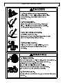
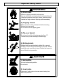
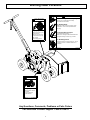
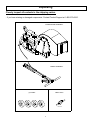
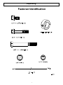
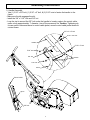
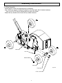
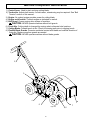
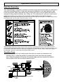
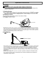
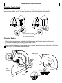
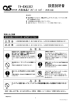
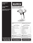
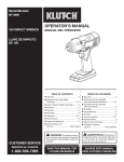
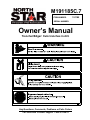
M191185C.7 ITEM NUMBER: 191185 SERIAL NUMBER: Owner’s Manual Trencher/Edger: Cuts trenches in dirt. Any Questions, Comments, Problems or Parts Orders Call NorthStar Product Support 1-800-270-0810 Table of Contents Hazard Signal Word Definitions………………………………......2 Important Safety Rules ................................................………..3,4 Warning Label Locations ............................................…………5 Unpacking ....................................................................……………6-7 Parts Identification .............................................…….….6 Fastener Identification .......................................…..……7 Assembly Instructions ....................................................…………. 8-9 Machine Component Identification.........................................…….10 Operation Instructions .................................................………..11-13 Work Site Preparation and Operating Zones ......……... 11 Trenching ...........................................................……….12 Changing Trench Depth & Blades.......................……… 13 Lockout Procedure, Maintenance and Storage ...........……….. 14,15 Lockout Procedure, Belt tension and Changing Blades... 14 Sheave Alignment and Storage………………......……..... 15 Specifications and Troubleshooting..................…………. 16 Parts Explosion ........................................………………..........…...17 Limited Warranty ........................................………………..........….19 Hazard Signal Word Definitions 2 Important Safety Rules 3 Important Safety Rules WARNING 3.) Fire hazard. Gasoline is highly flammable and explosive. You can be burned or seriously injured when handling fuel. -Stop the engine and keep heat, sparks, and flame away. -Handle fuel only outdoors. Wipe up spills immediately. 4.) Tripping hazard. Make sure area is clear of obstacles before trenching. Serious injury can result. Do not trench on wet, slippery grass. 5.) Tip-over hazard. Do not trench on hills with a slope greater than 15°. Trencher can tip over resulting in serious injury. 6.) Entanglement. Rotating blade can get tangled in debris left on ground resulting in serious injury and damage to trencher. Before trenching, make sure area is clear of debris that may wind around blade during operation. CAUTION 1.) Hot muffler. You can be burned by muffler. Do not touch. 2.) Loud noise. Exposure to loud engine noise can cause hearing loss. Wear ear protection. 4 Warning Label Locations DANGER 1.) Read safety manual completely. WARNING Serious injury or death will result if safety instructions are not followed. 2.) Rotating blade. Blade will cut and crush skin and bones. Keep hands clear. Follow lockout procedure before servicing. Flying objects. 3.) Buried cables and pipes. Rock and dirt may fly out while trenching. Serious injury can occur. -Pull trencher as you dig. Do not push. -Wear safety glasses. Call utilities before trenching. Blade will cut through buried electrical cables and gas pipes resulting in serious injury or death. 4.) Breathing hazard. Poisonous fumes from engine will kill you. Do not operate the trencher in enclosed areas even if ventilated. 2002 K-Bar Industries 800-270-0810 fig04829 WARNING Belt pinch point. Moving belts can cut skin and bones. Do not operate with guards removed. Any Questions, Comments, Problems or Parts Orders Call NorthStar Product Support 1-800-270-0810 5 Part No. 38035 Unpacking Closely inspect all contents in the shipping carton. - If you have missing or damaged components: Contact Product Support at 1-800-270-0810. ENGINE/FRAME ASSEMBLY HANDLE ASSEMBLY (4) WHEEL FRONT AXLE FIG01705 6 Unpacking Fastener Identification 7 Assembly Instructions 1.) Handle Assembly. - Use (1) 5/16” x 3/4” bolt, (1) 5/16” x 2” bolt, & (2) 5/16” nuts to fasten the handle to the frame. - Make sure the tab engages the slot. - Install the 3/8” x 3 1/4” bolt and 3/8” nut. - Loop the zip tie around the 3/8” bolt under the handle to loosely capture the control cable, make a loop approximately 1” diameter, trim off the excess zip tie. Caution: Tightening zip tie can result in abnormal ware to control cable jacket, assure control cable jacket does not contact frame. 3/8” x 3 1/4” bolt 5/16” x 3/4” bolt Handle 5/16” x 2” bolt 5/16” nut 3/8” nut slot/tab 5/16” nut Frame Control cable Zip tie 3/8” bolt Fig01707 8 Assembly Instructions 2.) Wheel Assembly - Check tires for correct air pressure prior to assembly. - Use a 5/32” hex wrench to attach (2) wheels to the front axle with (2) wheel retainers. Use (2) 5/16 x 3/4” bolts to fasten the front axle to the frame. - Fasten the (2) wheels to the frame with (2) wheel retainers. Frame 5/16” nut Wheel retainer Wheel Front Axle 5/16” x 3/4” bolt 9 fig01708 Machine Component Identification 1.) Control Lever. Used to start and stop cutting blade. 2.) Turnbuckle. Adjusts belt tension. As belts wear, retensioning may be required. See “Belt Tension” section of this manual. 3.) Engine. Air-cooled engine provides power for cutting blade. 4.) Engine on/off switch. Controls engine as indicated on switch. 5.) Belt Guard. Covers moving drive system of machine. CAUTION: NEVER operate machine without belt guards. 6.) Front Axle. Cutting depth is changed by moving axle to alternate hole locations. 7.) Cutting Blade. Creates trench in dirt. Check for missing teeth prior to digging trench. 8.) Flexible Blade Guards. Prevents accidental contact with blade and controls direction of flying dirt. Replace worn/torn guards as needed. CAUTION: NEVER operate machine without blade guards. 1 2 3 4 8 5 Fig01709 10 7 6 Operation Instructions Work Site Preparation The Trencher/Edger is operated by pulling the machine along a planned path. Mark your path before starting the trenching operation. Locate any aboveground obstacles in your path and plan a safe route to avoid them. Mark a well defined, easy to follow path. Move or cover objects that could be damaged by flying objects (windows, cars, siding, etc.). For safety reasons, plan your route to avoid pulling the trencher up any slopes. Do not trench on steep slopes (more than 15 degrees). NOTE: Always consult state and local building codes to determine the proper size and depth of the trench required for the job. Building codes vary from state to state and county to county. CO Poisoning: Exhaust from engine contains carbon monoxide, a poisonous gas that can cause carbon monoxide poisoning and possible death if inhaled. ONLY run trencher/edger OUTDOORS and at least 20 feet from the home, away from windows, vents and air intakes, to allow proper ventilation. If you start to feel sick, dizzy, or weak while using the trencher/edger, shut off the engine and get to fresh air RIGHT AWAY. Operating Zones Serious accidents can occur when people other than the operator are allowed into the operating zone, or when the machine is operated from areas other than the operating zone. Keep all bystanders 20 feet from the trencher/edger and never operate the machine from a position other than the defined operating zone. Trench FIG01711 Trench path Debris Area 11 Operation Instructions Trenching DANGER DO NOT PUSH MACHINE DURING OPERATION Trencher is designed as a “PULL” type machine only. Pushing the machine will expose the operator to flying debris. 1.) Starting Engine: Refer to Engine Owners’ Manual for proper engine starting procedure. DO NOT run engine more than 2 minutes without engaging blade, serious damage can occur to belts. 2.) Starting a Trench: Tilt machine from the handle to achieve free rotation of blade. 3.) Engage Control Lever: Front wheels Squeeze the Control Lever. SLOWLY lower the blade into the ground until the front wheels rest on the ground. Soil conditions influence the time it takes for the front wheels to contact the ground. Lowering the machine too quickly can stop the engine, if this condition persists, see the “Trouble Shooting” section of this manual. 4.) Pull Machine: Direction of travel Pull machine along the designated path. Trench cutting speed is influenced by trench depth and soil conditions. Do not jerk machine backwards while blade is engaged, damage will occur to the blade and/or drive train. Do not attempt to cut an angled trench as this will expose flying debris to the operator. Altering the design of the machine voids all warranties and liabilities. NOTE: Blade DOES NOT cut rock or concrete. If extreme resistance is felt and/or heard, stop lowering the Blade and try somewhere else. Excessive vibration/noise indicates an undesirable cutting condition. 12 Operation Instructions Changing Trench Depth The Trencher/Edger can cut a 7,6 or 5” deep trench. Simply unbolt the axle assembly and move it to the next hole pattern, or “flip” the axle assembly to achieve the desired cutting depth. 5” Trench 6” Trench 7” Trench “Flip” Axle Tire removed for clarity. Removal of tire NOT required to change trench depth. Changing Blades - Follow lockout procedure as outlined in the Maintenance and Storage section of this manual. - Tilt machine enough to gain access to blade with wrench. - Turn nut counterclockwise with 1 1/2” wrench to loosen. - When installing blade, make sure carbide tooth contacts ground before any other part of the blade. CAUTION: Do not install blade backward. Blade guard Blade Rotation Blade Rotation Ground Nut Carbide tooth 13 Maintenance and Storage Lockout Procedure Before performing maintenance, the trencher/edger must be placed in lockout mode. 1.) Turn off engine. 2.) Disconnect engine spark plug wire. Belt Tension 1. The ideal belt tension is the lowest tension at which the belts will not slip under peak load conditions. - Belts are too loose if a “squealing” noise is heard during operation. - Belt tension is too tight if engine cannot be started when all four wheels are resting on the ground. 2. Check belt tension after the first hour of operation. Recheck again after 20 hours of operation. Handle Control Cable Lock Nut Turnbuckle Lock Nut To adjust belt tension: 1. Loosen both Lock Nuts. 2. Hold Control Cable while turning turnbuckle. 3. Check belt tension by digging a trench. 4. Retighten Lock Nuts. CAUTION New belts require approximately 1 hour of use for proper break-in. DO NOT allow engine to run more than 2 minutes without engaging blade, serious damage can result to the belts. Changing Belt - Remove (4) 5/16” x ½” bolts and (2) 5/16” x ¾” bolts with nuts that fasten the guard in place. Remove belts from pulleys by hand, no tools are required. Install new belts in reverse order of removal. Run machine and retention belts as required. Excessive belt tension will shorten belt life. Never mix old belts and new belts. Never mix belts from different manufacturers. Keep belts free of foreign material. Do not use belt dressing. 14 Maintenance and Storage Sheave Alignment Eventually, sheave removal or replacement may become necessary. Inspect sheaves for cracks or a groove bottom that is shiny. Sheaves must be aligned to within 1/16” when reinstalled. 1/16” INCORRECT CORRECT CHECK ALIGNMENT CAUTION: After performing maintenance, make sure all guards, shields, and safety features are put back in place. Failure to follow this warning can result in serious injury. What When How Blade Before each use Check for missing carbide teeth/ bent blade Tires Each use Check pressure. The pressure rating is listed on the tire. Nuts and Bolts Each use Check for loose bolts. Moving Parts Each use Clear debris. Bearings Every 40 hours Use grease gun with axle grease. Refer to the engine owner’s manual for engine maintenance. Grease zerk Blade ITEM #191185 PARTS EXPLOSION TRENCHER/EDGER REV. C.7 Large pulley Storage 1.) Remove gasoline from engine or add fuel stabilizer to the gasoline to prevent gumming. 2.) Never store the trencher/edger where fumes might reach an open flame or spark. Allow the engine to cool before storing in any enclosure. 15 Specifications Engine................................................. 6.5 hp Honda Trench Depth (with standard blade).... 7” Trench Width (with standard blade).... 1 1/2” Overall Dimensions............................ 65 1/2” L x 26” W x 36 1/2” H Dry Weight.......................................... 137 lbs. Belt Size.............................................. A30K (Kevlar™ Reinforced) Blade RPM.......................................... 1850 The manufacturer reserves the right to make improvements in design and/or changes in specifications at any time without incurring any obligation to install them on units previously sold. Troubleshooting The following chart is intended for troubleshooting all aspects of the Trencher/Edger except the engine. Please refer to the engine owners’ manual for troubleshooting the engine. Problem Blade does not turn. Blade turns but does not cut ground. Machine “squeals” during trenching. Engine shuts down as machine is tilted. Machine vibrates excessively during trenching. Engine stalls when trenching Engine stalls when idling/starting Engine stalls when lowering starting a trench. See Cause: A, B, J C, D,K C, D E, F G, H, I, J L C C, E, F, G, J, K, M Cause A – Loose/Broken belts B - Control Cable broken C - Belt tension incorrect D - Belts are worn beyond acceptable limit E - Engine oil low F - Low level in gas tank G - Obstruction underground Solution Tighten/Replace belts Replace cable Retention Belt Purchase new belts Add oil per engine owners’ manual. Add gasoline Attempt to remove obstruction or start trenching further along path. Tighten bolts Replace bearings Replace blade See “Changing Blade” section for proper blade installation. Decrease rate of pull. Decrease rate of drop. H - Loose bolts I - Drive Shaft Bearings worn J - Blade bent/broken K - Blade installed incorrectly L - Pulling to fast M – Lowering machine too fast Any Questions, Comments, Problems or Parts Orders Call NorthStar Product Support 1-800-270-0810 16 Parts Explosion – Rev C.7 ITEM 1 2 3 4 5 6 7 8 9 10 11 12 13 14 15 16 17 18 19 20 PART# 606512 82142 37978 37938 788813 305200 38037 37958 82143 37976 37972 37959 37973 82221 37995 82216 82077 37991 82225 37948 DESCRIPTION 6.5 Honda Engine 3/16” x 2” Shaft Key 2AK27-3/4” Sheave Trencher Frame Wheel Wheel Retainer Warning Label Belt Guard 1/4” x 1 3/4” Key 2AK51-1” Sheave 1” Flange Bearing Front Axle Drive Shaft 1”-8 Jam Nut 1 1/2” x 7” Blade 1”-8 Hex Nut 1/4” x 2” Eye Bolt Idler Return Spring Spacer Idler Arm QTY 1 1 1 1 4 4 1 1 1 1 2 1 1 1 1 1 2 1 6 1 ITEM 21 22 23 24 25 26 27 28 29 30 31 32 33 34 35 36 37 38 39 40 17 PART# 37977 38068 37968 37962 37964 38036 38164 38035 37952 37974 37980 37982 37975 37949 37986 37970 30747 38310 37979 781903 DESCRIPTION Idler Pulley Belt Guard Control Cable Protective Mat Guard Retainer Warning Label Trench Path Label Danger Label Blade Guard Protective Mat Guard Retainer Guard Retainer Protective Mat Handle 1/4-20 Left Handed Nut Control Lever Hand Grip ¼” Turnbuckle A30K V-Belt ¼”- 28 x ¼” Set Screw QTY 1 1 1 1 1 1 1 1 1 1 1 1 1 1 1 1 2 1 2 4 This page has intentionally been left blank. 18 Limited Warranty Dear Valued Customer: The NorthStar Product you just purchased is built with the finest material and craftsmanship. Use this product properly and enjoy the benefits from its high performance. By purchasing a NorthStar product, you show a desire for quality and durability. Like all mechanical equipment this unit requires a due amount of care. Treat this unit like the high quality piece of machinery it is. Neglect and improper handling may impair its performance. Please thoroughly read the instructions and understand the operation before using your product. Limited Warranty NorthStar shall warranty any piece of equipment manufactured, or parts of equipment manufactured, to be free from defects in material or workmanship for a period of 2 years from the date of purchase by user. This warranty applies to the original purchaser of the equipment and is non transferable. Verification of purchase is the responsibility of the buyer. Parts will be replaced or repaired at no charge, except when the equipment has failed due to lack of proper maintenance. Any misuse, abuse, alteration or improper installation or operations will void warranty. Determining whether a part is to be replaced or repaired is the sole decision of NorthStar. NOTE: Some services performed by parties other than NorthStar may void warranty. This warranty covers parts only. It will not provide for replacement of complete products due to defective parts. Components not manufactured by NorthStar such as engines are guaranteed by their manufacturer and can be serviced at factory-authorized locations near you. Any costs incurred due to replacement or repair of items outside of a NorthStar approved facility is the responsibility of the buyer and not covered under warranty. NorthStar can supply you with the service center location in your area. This warranty specifically excludes the following; failure of parts due to damage caused by accident, fire, flood, windstorm, acts of God, applications not approved by NorthStar in writing, corrosion caused by chemicals, use of replacement parts which do not conform to manufacturer’s specifications, and damage caused by vandalism. Additional exclusions: loss of running time, inconvenience, loss of income, or loss of use, including any implied warranty of merchantability of fitness for a specific use. Warranty does not cover items subject to normal wear such as tires, receptacles or any part subject to direct physical contact by the public. This warranty does not cover any personal injury or damage to surrounding property caused by failure of any part. This warranty is in lieu of any other warranty expressed or implied and NorthStar assumes no other responsibility or liability outside that expressed within this warranty. Please fill in the following information and have it on hand when you call in a warranty claim. Customer Number: ______________________________________________________________ Date of Purchase: _______________________________________________________________ NorthStar Serial Number: _________________________________________________________ Item Number: __________________________________________________________________ 19 Manufactured by Northern Tool + Equipment Co., 2800 SouthCross Drive West P.O. Box 1499 Burnsville, MN 55337-0499 20