1
ASDA-A User Manual
Preface & Safety Precautions
Preface
Thank you very much for purchasing DELTA’s AC servo products. This manual will be helpful in the
installation, wiring, inspection, and operation of Delta AC servo drive and motor. Before using the product,
please read this user manual to ensure correct use. You should thoroughly understand all WARNINGS and
CAUTIONS before proceeding with the installation, wiring and operation. If you do not understand, please
contact your local Delta sales representative. Place this user manual in a safe location for future reference.
Using This Manual
Contents of this manual
This manual is a user guide that provides information on how to install, operate and maintain
ASDA-A series AC servo drives and ASMT series AC servo motors. The contents of this manual
are including the following topics:
z Installation of AC servo drives and motors
z Configuration and wiring
z Trial run steps
z Control functions and adjusting methods of AC servo drives
z Parameter settings
z Communication protocol
z Inspection and maintenance
z Troubleshooting
z Application examples
Who should use this manual
This user manual is intended for the following users:
z Those who are responsible for designing.
z Those who are responsible for installing or wiring.
z Those who are responsible for operating or programming.
z Those who are responsible for maintaining or troubleshooting.
Important precautions
Before using the product, please read this user manual thoroughly to ensure correct use and store
this manual in a safe and handy place for quick reference whenever necessary. Besides, please
observe the following precautions:
z Do not use the product in a potentially explosive environment.
z Install the product in a clean and dry location free from corrosive and inflammable gases or
liquids.
z Do not connect a commercial power supply to the U, V, W terminals of motor. Failure to
observe this precaution will damage either the Servo motor or drive.
z Ensure that the drive and motor are correctly connected to a ground. The grounding method
© DELTA ELECTRONICS, INC. ALL RIGHTS RESERVED
i
4th Edition 2005/11/30, HE03
Preface & Safety Precautions
z
z
z
z
ASDA-A User Manual
must comply with the electrical standard of the country.
Do not disconnect the AC servo drive and motor while the power is ON.
Do not attach, modify and remove wiring when power is applied to the AC servo drive and
motor.
Before starting the operation with a mechanical system connected, make sure the
emergency stop equipment can be energized and work at any time.
Do not touch the drive heat sink or the servo motor during operation. Otherwise, it may
result in serious personnel injury.
SAFETY PRECAUTIONS !
ASDA-A series drives are open type, variable frequency and insulated gate bipolar transistor AC monitor
controller incorporating microprocessor technology. They are operated from a single or three-phase source
of supply, and intended to control three-phase permanent magnet synchronous motors (PMSM) by means of
a variable frequency, variable voltage output, used in industrial applications and for installation in an end-use
enclosure. Drives, cables and motors are for use in a suitable enclosure with a minimum of a UL Type 1
rating.
Carefully notice and observe the following safety precautions when receiving, inspecting, installing,
operating, maintaining and troubleshooting. The following words, WARNING and CAUTION are used to
mark safety precautions when using the Delta’s servo products. Failure to observe these precautions may
void the warranty!
The words, WARNING and CAUTION, have the following meaning:
WARNING
Indicates a potentially hazardous situation and if not avoided,ʳmay result in serious
injury or death.
CAUTION
Indicates a potentially hazardous situation and if not avoided, may result in minor to
moderate injury or serious damage to the product.
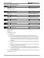
Unpacking Check
WARNING
zPlease
ensure that both the servo drive and motor are correctly matched for size
(power rating). Failure to observe this WARNING may cause fire, seriously damage
the drive / motor or cause personal injury.
Installation
CAUTION
zDo
not install the product in a location that is outside the stated specification for the
drive and motor. Failure to observe this caution may result in electric shock, fire, or
personal injury.
Wiring
WARNING
zConnect
the ground terminals to a class-3 ground (Ground resistance should not
exceed 100 :). Improper grounding may result in electric shock or fire.
4th Edition 2005/11/30, HE03
ii
© DELTA ELECTRONICS, INC. ALL RIGHTS RESERVED
ASDA-A User Manual
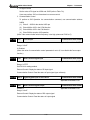
CAUTION
Preface & Safety Precautions
zDo
not connect any power suppies to the U, V, W terminals. Failure to observe this
precaution may result in serious injury, damage to the drive or fire.
zEnsure
that all screws, connectors and wire terminations are secure on the power
supply, servo drive and motor. Failure to observe this caution may result in damage,
fire or personal injury.
Operation
WARNING
zConduct
trial run on the servo motor with motor shaft disconnected from its
mechanical system to avoid any accidents.
zDo
not approach or touch any rotating parts (e.g. shaft) while the motor is running.
Failure to observe this precaution may result in serious injury to personnel.
zBefore
starting the operation with a mechanical system connected, change the drive
parameters to match the user-defined parameters of the mechanical system.
Starting the operation without matching the correct parameters may result in servo
drive or motor damage, or damage to the mechanical system.
zEnsure
that the emergency stop equipment or device is connected and working
correctly before operating the motor that is connected to a mechanical system.
zDo
not touch either the drive heat sink or the motor during operation as they may
become hot and personal injury may result.
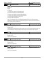
Maintenance and Inspection
WARNING
zDo
not touch any internal or exposed parts of the servo drive as electric shock may
result.
zDo
not remove the operation panel while the drive is connected to an electrical
power source otherwise electrical shock may result.
zWait
at least 10 minutes after power has been removed before touching any drive or
motor terminals or performing any wiring and/or inspection as an electrical charge
may still remain in the drive and motor with hazardous voltages even after power
has been removed.
zDo
not disassemble the servo drive or motor as electric shock may result.
zDo
not connect or disconnect wires or connectors while power is applied to the drive
and motor.
zOnly
qualified personnel who have electrical knowledge should conduct
maintenance and inspection.
Main Circuit Wiring
CAUTION
zUse
multi-stranded twisted-pair wires or multi-core shielded-pair wires for signal,
encoder (PG) feedback cables. The maximum length of command input cable is 3m
and the maximum length of encoder (PG) feedback cables is 20m.
© DELTA ELECTRONICS, INC. ALL RIGHTS RESERVED
iii
4th Edition 2005/11/30, HE03
Preface & Safety Precautions
CAUTION
ASDA-A User Manual
zInstall
the encoder cables in a separate conduit from the motor power cables to
avoid signal noise. Separate the conduits by 30cm.
zAs
a charge may still remain in the drive with hazardous voltages even after power
has been removed, be sure to wait at least 10 minutes after power has been
removed before performing any wiring and/or inspection.
zIt
is not recommended to frequently power the drive on and off. Do not turn the drive
off and on more than once per minute as high charging currents within the internal
capacitors may cause damage.
Main Circuit Terminal Wiring
CAUTION
zRemove
zInsert
the terminal block from the servo drive before wiring.
only one wire into one terminal on the terminal block.
zWhen
inserting wires ensure that the conductors are not shorted to adjacent
terminals or wires.
Trial Run without Load
CAUTION
zIn
order to prevent accidents, the trial run for servo motor should be conducted
under no load condition (run the servo motor alone without connecting couplings
and belts).
zFor
the initial trial run, do not operate the servo motor while it is connected to the
mechanical system. Connecting the motor to its mechanical system may cause
damage during the trail run. Connect the servo motor once it has successfully
completed a trail run.
Trial Run with Load
CAUTION
zAfter
4th Edition 2005/11/30, HE03
the trial run without load is completed, conduct a second trial run with load.
iv
© DELTA ELECTRONICS, INC. ALL RIGHTS RESERVED
ASDA-A User Manual
Table of Contents
Delta AC Servo Drive and Servo Motor
Ȫ ASDA-A Series ȫ User
Manual
T ABLE OF C ONTENTS
Preface and Safety Precautions . . . . . . . . . . . . . . . . . . . . . . . . . . . . . . . . . . . . . . . . . . . . . . i
Table of Contents . . . . . . . . . . . . . . . . . . . . . . . . . . . . . . . . . . . . . . . . . . . . . . . . . . . . . . . . . . . . . . . v
Chapter 1
Unpacking Check and Model Explanation . . . . . . . . . . . . . . . . . 1-1
1-1 Un pac k ing Chec k ................................................................................. 1-1
1-2 Model Expla nati on ............................................................................... 1-2
1-2-1 Na me plate .................................................................................... 1-2
1-2-2 Mod el Na me ................................................................................. 1-3
1-3 Servo Dri ve an d Se rvo Mo tor Co mb i nations ........................................... 1-5
1-4 Servo Dri ve F e atures ........................................................................... 1-7
1-5 Con trol Modes of Servo Dri ve ............................................................... 1-8
1-6 Molde d-case Ci rcuit Break er, F use a nd Le akag e Current ......................... 1-9
Chapter 2
Installation and Storage . . . . . . . . . . . . . . . . . . . . . . . . . . . . . . . . . . . . . . 2 - 1
2-1 I nstall ation No te s ................................................................................ 2-1
2-2 St ora ge Condi ti ons .............................................................................. 2-1
2-3 I nstall ation Co n ditions ......................................................................... 2-1
2-4 I nstall ation Proc edure an d Mi ni mu m Clea rance s ..................................... 2-2
Chapter 3
Configuration and Wiring ........................................... 3-1
3-1 Con fi gurati on ...................................................................................... 3-1
3-1-1 Con necting to Pe riphe ral De vice s .................................................... 3-1
3-1-2 Servo Dri ve Conn ecto rs and Te rmin als ............................................. 3-2
3-1-3 Wi ri ng Met ho ds .............................................................................. 3-3
3-1-4 Mot or Po wer Cabl e Co nnecto r Specificati o ns .................................... 3-4
3-1-5 Enc oder Co nn ector Spe c ifications ................................................... 3-6
3-1-6 Cab le Specifi cations fo r Servo Drive ................................................ 3-7
© DELTA ELECTRONICS, INC. ALL RIGHTS RESERVED
v
4th Edition 2005/11/30, HE03
Table of Contents
ASD-A User Manual
3-2 Basic Wiring ........................................................................................ 3-9
3-3 I npu t / Outp ut I nterf ace Conn ecto r -CN1 ................................................ 3-11
3-3-1 CN1 Terminal Identi ficat ion ............................................................. 3-11
3-3-2 Si g nals Expl anatio n of Co nnect o r CN1 ............................................. 3-13
3-3-3 Use r-de fined DI and DO si gnals ....................................................... 3-22
3-3-4 Wi ri ng Diagra ms of I / O Signals (CN1) .............................................. 3-25
3-4 Enco d er Conn ec tor CN2 ....................................................................... 3-28
3-5 Seri al Co mmuni cation Co nnecto r CN3 .................................................... 3-29
3-5-1 CN3 Terminal La yout an d Ide ntific ation ............................................ 3-29
3-5-2 Con nection b etween PC a nd Co nnecto r CN3 ..................................... 3-30
3-6 Stan d ard Con ne ction Exa mpl e ............................................................... 3-31
3-6-1 Posi tion (Pt ) Con trol M ode .............................................................. 3-31
3-6-2 Posi tion (Pr) Con trol M ode .............................................................. 3-32
3-6-3 Spe ed Cont ro l Mode ....................................................................... 3-33
3-6-4 Torq ue Cont ro l Mode ...................................................................... 3-34
Chapter 4
Display and Operation .............................................. 4-1
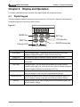
4-1 Digi ta l Ke ypad ..................................................................................... 4-1
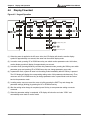
4-2 Displa y Flo wcha rt ................................................................................ 4-2
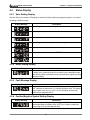
4-3 Stat us Displ a y ..................................................................................... 4-3
4-3-1 Sa ve Se ttin g Displa y ...................................................................... 4-3
4-3-2 Abo rt Setti ng Displa y ...................................................................... 4-3
4-3-3 Fa ul t Messag e Displ a y .................................................................... 4-3
4-3-4 Posi tive/ Nega t i ve Symbo l Set ting Displa y ......................................... 4-3
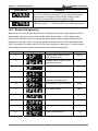
4-3-5 Mon itor Set tin g Dis pla y ................................................................... 4-4
4-4 Ge neral Func tio n Operati on .................................................................. 4-6
4-4-1 Erro r Sta tus Displa y Op eratio n ........................................................ 4-6
4-4-2 J OG Opera tio n ............................................................................... 4-6
4-4-3 Posi tion L earn ing Ope ra tion ............................................................ 4-7
4-4-4 DO signal F orce Outp ut Dia gnosi s Opera ti on .................................... 4-8
4-4-5 DI s i gnal Disp lay Di agn osis Operation .............................................. 4-9
4-4-6 DO signal Dis pla y Diag nosis Ope ration ............................................ 4-10
4th Edition 2005/11/30, HE03
vi
© DELTA ELECTRONICS, INC. ALL RIGHTS RESERVED
ASDA-A User Manual
Chapter 5
Table of Contents
Trial Run and Tuning Procedure ................................ 5-1
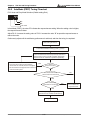
5-1 I nspe ction with out L oad ....................................................................... 5-1
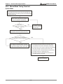
5-2 Appl yi ng Power to th e Dri ve .................................................................. 5-3
5-3 J O G Trial Run without Loa d .................................................................. 5-7
5-4 Sp eed Trial Run wit hout L oad ............................................................... 5-8
5-5 Positi on Tri al Run witho ut Load ............................................................ 5-10
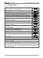
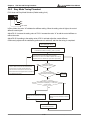
5-6 Tunin g Proced u re ................................................................................ 5-13
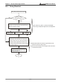
5-6-1 Tu ni ng Flo wch art ........................................................................... 5-14
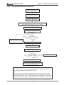
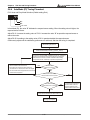
5-6-2 Lo a d Ine rtia Esti ma tio n Flo wcha rt ................................................... 5-15
5-6-3 Eas y Mode Tu ning Fl owchart ........................................................... 5-16
5-6-4 Aut oMode (PI ) Tuni ng F l owch art ...................................................... 5-18
5-6-5 Aut oMode (PDFF ) Tuni ng Flo wch art ................................................. 5-20
5-6-6 Man ual Mod e Tunin g Fl owcha rt ....................................................... 5-22
5-6-7 Li mi t of Loa d I nertia Es ti ma tion ....................................................... 5-23
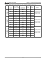
5-6-8 Rel ationshi p bet ween Tuning Mod es and Pa ra met ers ........................ 5-24
5-6-9 Gai n Adj ust ment in Ma nual Mo de ..................................................... 5-25
Chapter 6: Control Modes of Operation ........................................ 6-1
6-1 Con trol Modes of Ope rati on .................................................................. 6-1
6-2 Positi on Cont ro l Mode .......................................................................... 6-3
6-2-1 Co mma nd Source of Position (Pt ) Cont rol Mo de ................................ 6-4
6-2-2 Co mma nd Source of Position (Pr) Con trol Mo de ................................ 6-5
6-2-3 Stru cture of Position Co ntrol Mod e .................................................. 6-6
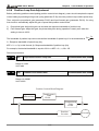
6-2-4 P-c urve Filte r for Posi ti on Cont ro l ................................................... 6-7
6-2-5 El ec tronic Ge ar Ratio ..................................................................... 6-9
6-2-6 Lo w-pass Filt er .............................................................................. 6-10
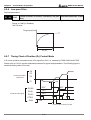
6-2-7 Ti mi ng Chart of Positio n (Pr) Co ntrol Mod e ...................................... 6-10
6-2-8 Posi tion L oop Gai n Adju stment ........................................................ 6-11
6-3 Sp eed Co ntrol Mo de ............................................................................ 6-13
6-3-1 Co mma nd Source of Speed Co nt rol Mo de ......................................... 6-14
6-3-2 Stru cture of Speed Co nt rol Mo de ..................................................... 6-15
6-3-3 Smo othing Strateg y of Speed Co nt rol Mo de ...................................... 6-16
6-3-4 Anal og In put Propo rtion a l Gain (Sc alar) ........................................... 6-19
© DELTA ELECTRONICS, INC. ALL RIGHTS RESERVED
vii
4th Edition 2005/11/30, HE03
Table of Contents
ASD-A User Manual
6-3-5 Ti mi ng Chart of Spee d Con trol M ode ................................................ 6-20
6-3-6 Spe ed Lo op Gain Adjust me nt ........................................................... 6-21
6-3-7 Res onance Suppressi o n .................................................................. 6-27
6-4 To rqu e Control Mo de ............................................................................ 6-29
6-4-1 Co mma nd Source of Torque Con trol Mode ........................................ 6-29
6-4-2 Stru cture of Torque Con trol Mode ..................................................... 6-30
6-4-3 Smo othing Strateg y of Torque Con trol Mode ...................................... 6-31
6-4-4 Anal og In put Propo rtion a l Gain (Sc alar) ............................................ 6-32
6-4-5 Ti mi ng Chart of Torq ue Con trol M ode ............................................... 6-33
6-5 Con trol Modes Selecti on ....................................................................... 6-34
6-5-1 Spe ed / Posi ti on Cont ro l Mode Se lection .......................................... 6-35
6-5-2 Spe ed / To rqu e Control Mo de Sel ection ............................................ 6-36
6-5-3 Torq ue / Posi ti on Cont ro l Mode Se lection ......................................... 6-37
6-6 Ot hers ................................................................................................ 6-38
6-6-1 Spe ed Li mit ................................................................................... 6-38
6-6-2 Torq ue Li mit ................................................................................... 6-39
6-6-3 Reg enera ti ve Resist or .................................................................... 6-40
6-6-4 Anal og Moni to r ............................................................................... 6-44
6-6-5 El ec tro ma gnet ic Brake .................................................................... 6-46
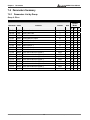
Chapter 7: Parameters ................................................................ 7-1
7-1 Defi ni tion ............................................................................................ 7-1
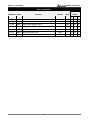
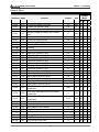
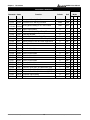
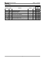
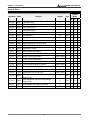
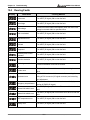
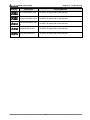
7-2 Para meter Su mma ry ............................................................................. 7-2
7-2-1 Paramete rs L i st b y Gro up ............................................................... 7-2
7-2-2 Paramete rs L i st b y Fun ction ............................................................ 7-9
7-3 De tail ed Para meter Listin gs .................................................................. 7-20
Chapter 8: MODBUS Communications .......................................... 8-1
8-1 Co mmunicatio n Hardware Interface ....................................................... 8-1
8-2 Co mmunicatio n Para mete r Set tings ....................................................... 8-4
8 - 3 M O D B U S C o m m u n i c a t i o n Pro tocol ......................................................... 8-7
8-4 Co mmunicatio n Para mete r Write -in and Rea d-out .................................... 8-14
4th Edition 2005/11/30, HE03
viii
© DELTA ELECTRONICS, INC. ALL RIGHTS RESERVED
ASDA-A User Manual
Table of Contents
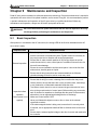
Chapter 9: Maintenance and Inspection ........................................ 9-1
9-1 Basic Inspecti on .................................................................................. 9-1
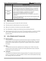
9-2 Maint enance ....................................................................................... 9-2
9-3 Li fe of Re place me nt Co mponen ts .......................................................... 9-2
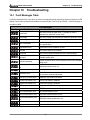
Chapter 10: Troubleshooting ....................................................... 10-1
10-1 Faul t Message s Table ........................................................................ 10-1
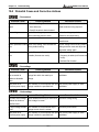
10-2 Po te ntial Caus e and Correcti ve Ac tions ............................................... 10-2
10-3 Cle a ring Faul ts .................................................................................. 10-8
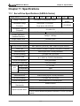
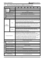
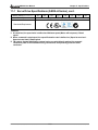
Chapter 11: Specifications .......................................................... 11-1
11-1 Servo Dri ve Specificati o ns (ASDA-A Seri es) ......................................... 11-1
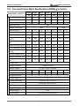
11-2 Lo w Inert ia Se rvo Mo tor Speci ficat ions (ASMT
L Se ries) .................... 11-4
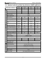
11-3 Medi um Ine rtia Se rvo Mo tor Sp ecifi cations (ASMT
M Se ries).............. 11-5
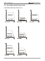
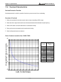
11-4 Servo Moto r Speed-Torq ue Curves ....................................................... 11-6
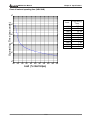
11-5 Overload Cha racteris tics .................................................................... 11-8
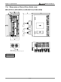
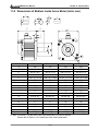
11-6 Di me nsions o f Servo Dri ve .................................................................. 11-10
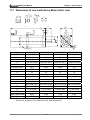
11-7 Di me nsions o f Low Ine rti a Se rvo Motor ................................................ 11-13
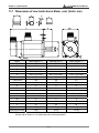
11-8 Di me nsions o f Me diu m I n ertia Se rvo Moto r ........................................... 11-15
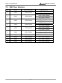
11-9 EMI Filters Sel ection .......................................................................... 11-16
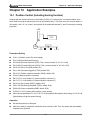
Chapter 12: Application Examples................................................ 12-1
12-1 Posi t i on Cont rol (incl udi ng ho mi ng functi on) ......................................... 12-1
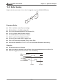
12-2 Roll e r Fe eding ................................................................................... 12-3
12-3 Connecting to Delta DVP-EH Series PLC ............................................... 12-4
12-4 Connecting to Delta TP04 Series ........................................................... 12-9
12-5 Position Control Mode (Pr Mode)........................................................... 12-11
12-6 Feed Step Control ............................................................................... 12-14
12-7 Internal Auto Running Mode .................................................................. 12-25
12-8 Homing Function ................................................................................. 12-30
12-9 External Controller Connection Examples............................................... 12-37
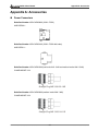
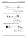
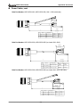
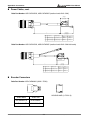
Appendix A: Accessories ............................................................. A-1
© DELTA ELECTRONICS, INC. ALL RIGHTS RESERVED
ix
4th Edition 2005/11/30, HE03
Table of Contents
ASD-A User Manual
About this Manual…
Use r Info rma tio n
Be sure to store this manual in a safe place.
D u e t o c o n s ta n t l y g r o w i n g p r o d u c t r a n g e , t e c h n i c a l i m p r o v e m e n t a n d a l t e r a t i o n o r c h a n g e d
t e x ts , f i g u r e s a n d d i a g r a m s , w e r e s e r v e t h e r i g h t o f t h i s m a n u a l c o n ta i n e d i n f o r m a t i o n
change without prior notice.
C o p i n g o r r e p r o d u c i n g a n y pa r t o f t h i s m a n u a l , w i t h o u t w r i t t e n c o n s e n t o f D e l ta E l e c t r o n i c s
Inc. is prohibited.
Tec hni cal Su ppo rt and Se rvi ce
We l c o m e t o c o n ta c t u s o r v i s i t o u r w e b s i t e ( h t t p : / / w w w. d e l ta . c o m . t w / i n d u s t r i a l a u t o m a t i o n / )
i f y o u n e e d a n y t e c h n i c a l s u p p o r t , s e r v i c e a n d i n f o r m a t i o n , o r, i f y o u h a v e a n y q u e s t i o n i n
u s i n g t h e p r o d u c t . We a r e l o o k i n g f o r w a r d t o s e r v e y o u n e e d s a n d w i l l i n g t o o ff e r o u r b e s t
support and service to you. Reach us by the following ways.
ASIA
D E LTA E L E C T R O N I C S , I N C .
TA O Y U A N P l a n t /
3 1 - 1 , S H I E N PA N R O A D , K U E I S A N
I N D U S T R I A L Z O N E TA O Y U A N 3 3 3 ,
TA I WA N
TEL: 886-3-362-6301
FA X : 8 8 6 - 3 - 3 6 2 - 7 2 6 7
J A PA N
D E LTA E L E C T R O N I C S ( J A PA N ) I N C .
Sales Office/
D E LTA S H I B A D A I M O N B L D G.
2 - 1 - 1 4 S H I B A D A I M O N , M I N ATO - K U ,
TO K Y O , 1 0 5 - 0 0 1 2 , J A PA N
T E L : 8 1 - 3 - 5 7 3 3 - 1111
FA X : 8 1 - 3 - 5 7 3 3 - 1 2 11
NORTH/SOUTH AMERICA
D E LTA P R O D U C T S C O R P O R AT I O N
Sales Office/
P. O . B O X 1 2 1 7 3
5 1 0 1 D AV I S D R I V E
R E S E A R C H T R I A N G L E PA R K ,
NC 27709, U.S.A.
TEL: 1-919-767-3813
FA X : 1 - 9 1 9 - 7 6 7 - 3 9 6 9
4th Edition 2005/11/30, HE03
EUROPE
D E LT R O N I C S ( N E T H E R L A N D S ) B . V.
Sales Office/
DE WITBOGT 15
5652 AG EINDHOVEN
THE NETHERLANDS
TEL: 31-40-259-2850
FA X : 3 1 - 4 0 - 2 5 9 - 2 8 5 1
x
© DELTA ELECTRONICS, INC. ALL RIGHTS RESERVED
ASDA-A User Manual
Chapter 1 Unpacking Check and Model Explanation
Chapter 1 Unpacking Check and Model Explanation
1-1
Unpacking Check
After receiving the product, please check for the following:
Ensure that the product is what you have ordered.
Verify the part number indicated on the nameplate corresponds with the part number of your order
(Please refer to Section 1-2 for details about the model explanation).
Ensure that the servo motor shaft rotates freely.
Rotate the motor shaft by hand; a smooth rotation will indicate a good motor. However, a servo motor
with an electromagnetic brake can not be rotated manually.
Check for damage.
Inspect the unit to insure it was not damaged during shipment.
Check for loose screws.
Ensure that all necessary screws are tight and secure. If any items are damaged or incorrect, please
inform the distributor whom you purchased the product from or your local Delta sales representative.
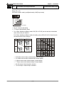
A complete and workable AC servo system should be including the following parts:
Part I : Delta standard supplied parts
(1)
Servo drive
(2)
Servo motor
(3)
5 PIN Terminal Block (for L1, L2, R, S, T)
(4)
3 PIN Terminal Block (for U, V, W)
(5)
3 PIN Terminal Block (for P, D, C)
(6)
One operating lever (for wire to terminal block insertion)
Part II : Optional parts, not Delta standard supplied part (Refer to Appendix A)
(1)
One power cable, which is used to connect servo motor and U, V, W terminals of servo drive. This
power cable is with one green grounding cable. Please connect the green grounding cable to the
ground terminal of the servo drive.
(2)
One encoder cable, which is used to connect the encoder of servo motor and CN2 terminal of
servo drive.
(3)
CN1 Connector: 50 PIN Connector (3M type analog product)
(4)
CN2 Connector: 20 PIN Connector (3M type analog product)
© DELTA ELECTRONICS, INC. ALL RIGHTS RESERVED
1-1
4th Edition 2005/11/30, HE03
Chapter 1 Unpacking Check and Model Explanation
(5)
1-2
ASDA-A User Manual
CN3 Connector: 6 PIN Connector (IEEE1394 analog product)
Model Explanation
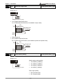
1-2-1 Nameplate
ASDA-A Series Servo Drive
Nameplate Explanation
Serial Number Explanation
4th Edition 2005/11/30, HE03
1-2
© DELTA ELECTRONICS, INC. ALL RIGHTS RESERVED
ASDA-A User Manual
Chapter 1 Unpacking Check and Model Explanation
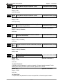
ASMT Series Servo Motor
Nameplate Explanation
Serial Number Explanation
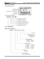
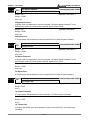
1-2-2 Model Name
ASDA-A Series Servo Drive
© DELTA ELECTRONICS, INC. ALL RIGHTS RESERVED
1-3
4th Edition 2005/11/30, HE03
Chapter 1 Unpacking Check and Model Explanation
ASDA-A User Manual
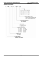
ASMT Series Servo Motor
4th Edition 2005/11/30, HE03
1-4
© DELTA ELECTRONICS, INC. ALL RIGHTS RESERVED
ASDA-A User Manual
1-3
Chapter 1 Unpacking Check and Model Explanation
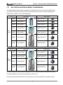
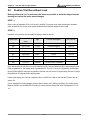
Servo Drive and Servo Motor Combinations
The tables below show the possible combination of Delta ASDA-A series servo drives and ASMT series
servo motors. The boxes (
) at the end of the model names are for version or optional configurations.
(Please refer to Section 1-2 for model explanation)
Servo drive
Low
inertia
Servo motor
100W
ASD-A0121L
ASMT01L250
200W
ASD-A0221L
ASMT02L250
400W
ASD-A0421L
ASMT04L250
750W
ASD-A0721L
ASMT07L250
1000W
ASD-A1021L
ASMT10L250
2000W
ASD-A2023L
ASMT20L250
3000W
ASD-A3023L
ASMT30L250
Servo drive
Medium
inertia
Servo motor
1000W
ASD-A1021M
ASMT10M250
1500W
ASD-A1521M
ASMT15M250
2000W
ASD-A2023M
ASMT20M250
3000W
ASD-A3023M
ASMT30M250
The drives shown in the above table are designed for use in combination with the specific servo motors.
Check the specifications of the drives and motors you want to use.
Also, please ensure that both the servo drive and motor are correctly matched for size (power rating).
© DELTA ELECTRONICS, INC. ALL RIGHTS RESERVED
1-5
4th Edition 2005/11/30, HE03
Chapter 1 Unpacking Check and Model Explanation
ASDA-A User Manual
If the power of motor and drive is not within the specifications, the drive and motor may overheat and
servo alarm would be activated. For the detail specifications of servo drives and motors, please refer to
Chapter 11 “Specifications”.
The drives shown in the above table are designed according to the three multiple of rated current of
motors shown in the above table. If the drives which are designed according to the six multiple of rated
current of motors are needed, please contact our distributors.
4th Edition 2005/11/30, HE03
1-6
© DELTA ELECTRONICS, INC. ALL RIGHTS RESERVED
ASDA-A User Manual
1-4
Chapter 1 Unpacking Check and Model Explanation
Servo Drive Features
© DELTA ELECTRONICS, INC. ALL RIGHTS RESERVED
1-7
4th Edition 2005/11/30, HE03
Chapter 1 Unpacking Check and Model Explanation
1-5
ASDA-A User Manual
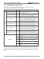
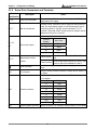
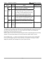
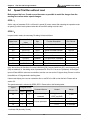
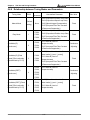
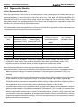
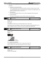
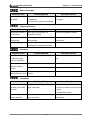
Control Modes of Servo Drive
The Delta Servo can be programmed to provide six single and five dual modes of operation.
Their operation and description is listed in the following table.
Mode
Description
External Position Control
Pt
Position control for the servo motor is achieved via an
external pulse command.
Internal Position Control
Pr
Position control for the servo motor is achieved via by 8
commands stored within the servo controller. Execution
of the 8 positions is via Digital Input (DI) signals.
S
Speed control for the servo motor can be achieved via
parameters set within the controller or from an external
analog -10 ~ +10 Vdc command. Control of the internal
speed parameters is via the Digital Inputs (DI). (A
maximum of three speeds can be stored internally).
Sz
Speed control for the servo motor is only achieved via
parameters set within the controller. Control of the
internal speed parameters is via the Digital Inputs (DI). (A
maximum of three speeds can be stored internally).
T
Torque control for the servo motor can be achieved via
parameters set within the controller or from an external
analog -10 ~ +10 Vdc command. Control of the internal
torque parameters is via the Digital Inputs (DI). (A
maximum of three torque levels can be stored internally).
Speed Control
Single
Mode
Code
Internal Speed Control
Torque Control
Tz
Torque control for the servo motor is only achieved via
parameters set within the controller. Control of the
internal torque parameters is via the Digital Inputs (DI). (A
maximum of three torque levels can be stored internally).
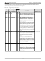
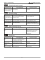
Pt-S
Either Pt or S control mode can be selected via the Digital
Inputs (DI)
Pt-T
Either Pt or T control mode can be selected via the Digital
Inputs (DI)
Pr-S
Either Pr or S control mode can be selected via the
Digital Inputs (DI)
Pr-T
Either Pr or T control mode can be selected via the Digital
Inputs (DI)
S-T
Either S or T control mode can be selected via the Digital
Inputs (DI)
Internal Torque Control
Dual Mode
The above control modes can be accessed and changed via by parameter P1-01. If the control mode is
changed, switch the drive off and on after the new control mode has been entered. The new control mode
will only be valid after drive off/on action. Please see CAUTION on page iv (switching drive off/on multiple
times).
4th Edition 2005/11/30, HE03
1-8
© DELTA ELECTRONICS, INC. ALL RIGHTS RESERVED
ASDA-A User Manual
1-6
Chapter 1 Unpacking Check and Model Explanation
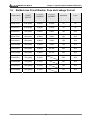
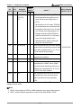
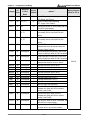
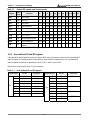
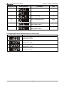
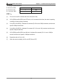
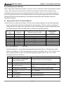
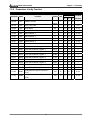
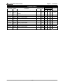
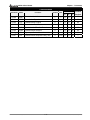
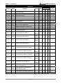
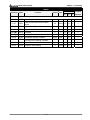
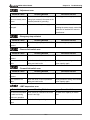
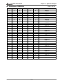
Molded-case Circuit Breaker, Fuse and Leakage Current
Model Name
OUTPUT
SHORT
CIRCUIT
LEAKING
CURRENT
LEAKING
CURRENT
BREAKER
FUSE
Operation Mode
General
3-Phase
1-Phase
General
General
ASD-A0121LA
8.4A (peak)
0.06mA
0.16mA
5A
5A
ASD-A0221LA
8.4A (peak)
0.06mA
0.16mA
5A
5A
ASD-A0421LA
25A (peak)
0.08mA
0.2mA
10A
20A
ASD-A0721LA
42A (peak)
0.08mA
0.2mA
10A
20A
ASD-A1021LA
60A (peak)
0.08mA
0.2mA
15A
25A
ASD-A1021MA
60A (peak)
0.08mA
0.2mA
15A
25A
ASD-A1521LA
66A (peak)
0.09mA
0.21mA
20A
40A
ASD-A1521MA
66A (peak)
0.09mA
0.21mA
20A
40A
ASD-A2023LA
73A (peak)
0.12mA
30A
60A
ASD-A2023MA
73A (peak)
0.12mA
30A
60A
ASD-A3023LA
107A (peak)
0.13mA
30A
80A
ASD-A3023MA
107A (peak)
0.13mA
30A
80A
© DELTA ELECTRONICS, INC. ALL RIGHTS RESERVED
1-9
4th Edition 2005/11/30, HE03
Chapter 1 Unpacking Check and Model Explanation
ASDA-A User Manual
This page intentionally left blank.
4th Edition 2005/11/30, HE03
1-10
© DELTA ELECTRONICS, INC. ALL RIGHTS RESERVED
ASDA-A User Manual
Chapter 2 Installation and Storage
Chapter 2 Installation and Storage
2-1
Installation Notes
Pay close attention on the following installation notes:
1) Do not bend or strain the connection cables between servo drive and motor.
2) When mounting servo drive, make sure to tighten screws to secure the drive in place.
3) If the servo motor shaft is coupled directly to a rotating device ensure that the alignment specifications
of the servo motor, coupling, and device are followed. Failure to do so may cause unnecessary loads or
premature failure to the servo motor.
4) If the length of cable connected between servo drive and motor is more than 20m, please increase the
wire gauge of the encoder cable and motor connection cable (connected to U, V, W terminals).
5) Make sure to tighten the screws for securing motor.
2-2
Storage Conditions
The product should be kept in the shipping carton before installation. In order to retain the warranty
coverage, the AC drive should be stored properly when it is not to be used for an extended period of time.
Some storage suggestions are:
Store in a clean and dry location free from direct sunlight.
Store within an ambient temperature range of -20°C to +65°C (-4°F to 149°F).
Store within a relative humidity range of 0% to 95% and non-condensing.
Do not store in a place subjected to corrosive gases and liquids.
Correctly packaged and placed on a solid surface.
2-3
Installation Conditions
Operating Temperature
ASDA-A Series Servo Drive
: 0°C to 55°C (32°F to 131°F)
ASMT Series Servo Motor
: 0°C to 40°C (32°F to 104°F)
The ambient temperature of servo drive for long-term reliability should be under 45°C (113°F).
If the ambient temperature of servo drive is greater than 45°C (113°F), please install the drive in a wellventilated location and do not obstruct the airflow for the cooling fan.
Caution
The servo drive and motor will generate heat. If they are installed in a control panel, please ensure
sufficient space around the units for heat dissipation.
© DELTA ELECTRONICS, INC. ALL RIGHTS RESERVED
2-1
4th Edition 2005/11/30, HE03
Chapter 2 Installation and Storage
ASDA-A User Manual
Pay particular attention to vibration of the units and check if the vibration has impacted the electric devices
in the control panel. Please observe the following precautions when selecting a mounting location. Failure
to observe the following precautions may void the warranty!
Do not mount the servo drive or motor adjacent to heat-radiating elements or in direct sunlight.
Do not mount the servo drive or motor in a location subjected to corrosive gases, liquids, or airborne
dust or metallic particles.
Do not mount the servo drive or motor in a location where temperatures and humidity will exceed
specification.
Do not mount the servo drive or motor in a location where vibration and shock will exceed
specification.
Do not mount the servo drive or motor in a location where it will be subjected to high levels of
electromagnetic radiation.
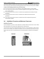
2-4
Installation Procedure and Minimum Clearances
Installation Procedure
Incorrect installation may result in a drive malfunction or premature failure of the drive and or motor. Please
follow the guidelines in this manual when installing the servo drive and motor.
The AC servo drive should be mounted perpendicular to the wall or in the control panel. In order to ensure
the drive is well ventilated, ensure that the all ventilation holes are not obstructed and sufficient free space
is given to the servo drive. Do not install the drive in a horizontal position or malfunction and damage will
occur.
4th Edition 2005/11/30, HE03
2-2
© DELTA ELECTRONICS, INC. ALL RIGHTS RESERVED
ASDA-A User Manual
Chapter 2 Installation and Storage
Drive Mounting
Servo drives must be back mounted vertically on a dry and solid surface such as a NEMA enclosure. A
minimum spacing of two inches must be maintained above and below the drive for ventilation and heat
dissipation. Additional space may be necessary for wiring and cable connections. Also, as the drive
conducts heat away via the mounting, the mounting plane or surface should be conductor away and not
conduct heat into the drive from external sources
Motor Mounting
Servo motors should be mounted firmly to a dry and solid mounting surface to ensure maximum heat
transfer for maximum power output and to provide a good ground.
For the dimensions and weights specifications of servo drive or motor, please refer to Chapter 11
"Specifications".
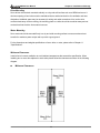
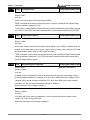
Minimum Clearances
Install a fan to increase ventilation to avoid ambient temperatures that exceed the specification. When
installing two or more drive adjacent to each other please follow the clearances as shown in the following
diagram.
Minimum Clearances
© DELTA ELECTRONICS, INC. ALL RIGHTS RESERVED
2-3
4th Edition 2005/11/30, HE03
Chapter 2 Installation and Storage
ASDA-A User Manual
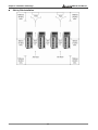
Side by Side Installation
4th Edition 2005/11/30, HE03
2-4
© DELTA ELECTRONICS, INC. ALL RIGHTS RESERVED
ASDA-A User Manual
Chapter 3
Chapter 3 Configuration and Wiring
Configuration and Wiring
This chapter provides information on wiring ASDA-A series products, the descriptions of I/O signals and
gives typical examples of wiring diagrams.
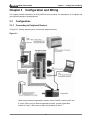
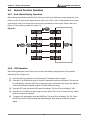
3-1
Configuration
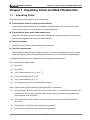
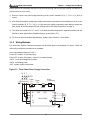
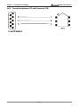
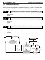
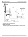
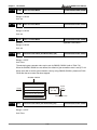
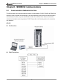
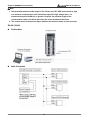
3-1-1 Connecting to Peripheral Devices
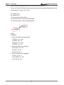
In Figure 3.1, it briefly explains how to connect each peripheral device.
Figure 3.1
"When using an external regenerative resistor, ensure P and D is closed, and P and
C is open. When using an internal regenerative resistor, connect regenerative
resistor to P and C, and ensure an open circuit between P and D."
© DELTA ELECTRONICS, INC. ALL RIGHTS RESERVED
3-1
4th Edition 2005/11/30, HE03
Chapter 3 Configuration and Wiring
ASDA-A User Manual
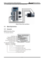
3-1-2 Servo Drive Connectors and Terminals
Terminal
Identification
L1, L2
R, S, T
Description
Notes
Control circuit terminal
The servo Control Circuit requires an independent 220V
single-phase VAC supply.
Main circuit terminal
The Main Circuit Terminal is used to supply the servo with line
power. If a single-phase supply, is used connect the R and S
terminals to power. If 3-phase, connect all three R, S, & T
terminals. To provide Control Circuit power two jumpers can be
added from R and S to L1 and L2.
Used to connect servo motor
U, V, W
FG
P, D, C
CN1
Servo motor output
Regenerative resistor
terminal
Terminal
Symbol
Wire Color
U
Red
V
White
W
Black
FG
Green
Internal resistor
Ensure P and D is closed, and P and C is
open.
External resistor
Connect regenerative resistor to P and C, and
ensure an open circuit between P and D.
Ground terminal
Used to connect grounding wire of power supply and servo
motor.
I/O connector
Used to connect external controllers. Please refer to section 3-3
for details.
Used to connect encoder of servo motor. Please refer to section
3-4 for details.
CN2
CN3
Encoder connector
Terminal Symbol
Wire Color
A
Blue
/A
Blue/Black
B
Green
/B
Green/Black
Z
Yellow
/Z
Yellow/Black
VCC
Red
GND
Black
Communication connector Used to connect PC or controller. Refer to section 3-5 for details.
Note: U, V ,W , CN1, CN2, CN3 terminals provide short circuit protection.
4th Edition 2005/11/30, HE03
3-2
© DELTA ELECTRONICS, INC. ALL RIGHTS RESERVED
ASDA-A User Manual
Chapter 3 Configuration and Wiring
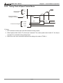
Please observe the following precautions while performing wiring and touching any electrical connections on
the servo drive or servo motor.
1) Ensure to check if the power supply and wiring of the "power" terminals (R, S, T, L1, L2, U, V, & W) is
correct.
2) As a residual hazardous voltage may remain inside the drive, please do not immediately touch any of the
"power" terminals (R, S, T, L1, L2, U, V, & W) and/or the cables connected to them after the power has
been turned off and the charge LED is lit. (Please refer to the Safety Precautions on page ii).
3) The cables connected to R, S, T and U, V, W terminals should be placed in separate conduits from the
encoder or other signal cables. Separate them by at least 30cm (12").
4) For the connectors and cables specifications, please refer to section 3-1-6 for details.
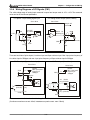
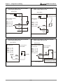
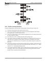
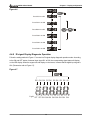
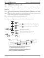
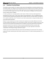
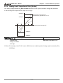
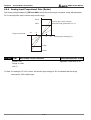
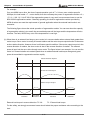
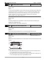
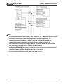
3-1-3 Wiring Methods
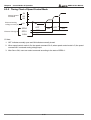
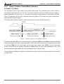
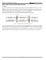
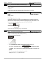
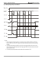
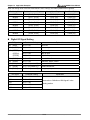
For drives from 100W to 1kW the input power can be either single or three-phase. For drives 1.5kW and
above only three-phase connections are available.
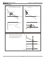
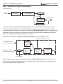
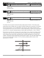
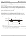
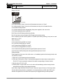
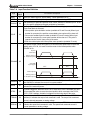
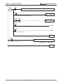
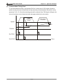
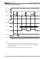
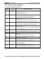
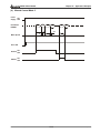
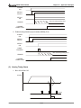
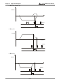
In the wiring diagram figures 3.2 & 3.3:
Power ON : contact “a” (normally open).
Power OFF or Alarm Processing : contact “b” (normally closed).
1MC/x : coil of electromagnetic contactor
1MC/a : self-holding power
1MC : contact of main circuit power.
Figure 3.2 Three-Phase Power Supply Connection
R S T
1MCCB
Noise filter
Power
On
1MC/x
1MC/a
R
1MC
S
T
1MC
Alarm
Processing
Power
Off
SUP
Servo Drive
U
V
W
M
L1
L2
PE
© DELTA ELECTRONICS, INC. ALL RIGHTS RESERVED
3-3
4th Edition 2005/11/30, HE03
Chapter 3 Configuration and Wiring
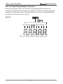
ASDA-A User Manual
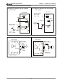
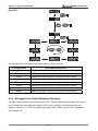
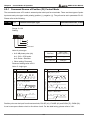
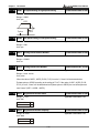
Figure 3.3 Single-Phase Power Supply Connection (for 1kW and below)
R S
1MCCB
Alarm
Processing
Power Power
Noise filter
On
Off
1MC/x
1MC/a
R
1MC
S
T
SUP
U
Servo Drive
V
W
1MC
M
L1
L2
PE
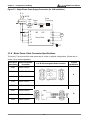
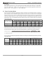
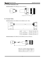
3-1-4 Motor Power Cable Connector Specifications
The boxes (
) at the end of the model names are for version or optional configurations. (Please refer to
section 1-2 for model explanation.)
Servo Drive
Motor Part Number
Power Rating
Description
100W
ASMT01L250A
200W
ASMT02L250A
400W
ASMT04L250A
750W
ASMT07L250A
100W
ASMT01L250B
200W
ASMT02L250B
400W
ASMT04L250B
750W
ASMT07L250B
U, V, W / Electromagnetic Brake Connector
Terminal
Identification
A
4th Edition 2005/11/30, HE03
B
3-4
© DELTA ELECTRONICS, INC. ALL RIGHTS RESERVED
ASDA-A User Manual
Chapter 3 Configuration and Wiring
Servo Drive
Motor Part Number
Power Rating
Description
1kW
U, V, W / Electromagnetic Brake Connector
Terminal
Identification
ASMT10L250
ASMT10M250
1.5kW
ASMT15M250
2kW
ASMT20L250
3kW
ASMT30L250
C
20-18
2kW
ASMT20M250
3kW
ASMT30M250
D
24-11
Terminal
W
V
U
CASE GROUND
BRAKE1
BRAKE2
Identification
(Black)
(White)
(Red)
(Green)
(Orange)
(Yellow)
A
A3
A2
A1
A4
-
-
B
1
2
3
4
6
5
C
B
I
F
E
G
H
D
F
E
D
G
A
B
© DELTA ELECTRONICS, INC. ALL RIGHTS RESERVED
3-5
4th Edition 2005/11/30, HE03
Chapter 3 Configuration and Wiring
ASDA-A User Manual
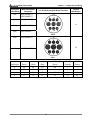
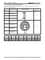
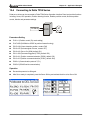
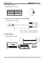
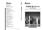
3-1-5 Encoder Connector Specifications
The boxes (
) at the end of the model names are for version or optional configurations. (Please refer to
section 1-2 for model explanation.)
Servo Drive
Capacity
100W
Motor Model Name
Terminal
Encoder Connector
Identification
ASMT01L250
A1
200W
ASMT02L250
400W
ASMT04L250
750W
ASMT07L250
1kW
ASMT10L250
A
A9
ASMT10M250
1.5kW
ASMT15M250
2kW
ASMT20L250
B
ASMT20M250
3kW
ASMT30L250
20-29
ASMT30M250
17-#16
Terminal
A
/A
B
/B
Z
/Z
5V
GND
BRAID
Identification (Blue) (Blue/Black) (Green) (Green/Black) (Yellow) (Yellow/Black) (Red) (Black) SHELD
A
A1
A2
A3
A4
A5
A6
A7
A8
A9
B
A
B
C
D
F
G
S
R
-
4th Edition 2005/11/30, HE03
3-6
© DELTA ELECTRONICS, INC. ALL RIGHTS RESERVED
ASDA-A User Manual
Chapter 3 Configuration and Wiring
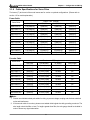
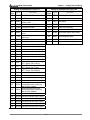
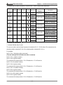
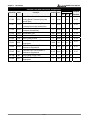
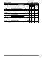
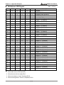
3-1-6 Cable Specifications for Servo Drive
The boxes (
) at the end of the model names are for version or optional configurations. (Please refer to
section 1-2 for model explanation.)
Power Cable
Servo Drive
Power ~ mm2 (Gauge)
L1, L2
R, S, T
U, V, W
P, C
ASD-A0121L
1.25(AWG16)
2(AWG14)
2(AWG16)
2(AWG14)
ASD-A0221 L
1.25(AWG16)
2(AWG14)
2(AWG16)
2(AWG14)
ASD-A0421 L
1.25(AWG16)
2(AWG14)
2(AWG16)
2(AWG14)
ASD-A0721 L
1.25(AWG16)
2(AWG14)
2(AWG16)
2(AWG14)
ASD-A1021 L
1.25(AWG16)
2(AWG14)
2(AWG12)
2(AWG14)
ASD-A1021M
1.25(AWG16)
2(AWG14)
2(AWG12)
2(AWG14)
ASD-A1521M
1.25(AWG16)
2(AWG14)
2(AWG12)
2(AWG14)
ASD-A2023 L
1.25(AWG16)
2(AWG14)
2(AWG12)
2(AWG14)
ASD-A2023 M
1.25(AWG16)
2(AWG14)
2(AWG12)
2(AWG14)
ASD-A3023 L
1.25(AWG16)
3.5(AWG12)
3.5(AWG10)
2(AWG14)
ASD-A3023 M
1.25(AWG16)
3.5(AWG12)
3.5(AWG10)
2(AWG14)
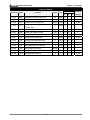
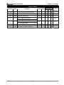
Encoder Cable
Servo Drive
Encoder ~ mm2 (Gauge)
Wire Size
Core Number
UL Rating
Wire Length
ASD-A0121L
(AWG26)
10 core (4 pair)
UL2464
3m
ASD-A0221 L
(AWG26)
10 core (4 pair)
UL2464
3m
ASD-A0421 L
(AWG26)
10 core (4 pair)
UL2464
3m
ASD-A0721 L
(AWG26)
10 core (4 pair)
UL2464
3m
ASD-A1021 L
(AWG26)
10 core (4 pair)
UL2464
3m
ASD-A1021M
(AWG26)
10 core (4 pair)
UL2464
3m
ASD-A1521M
(AWG26)
10 core (4 pair)
UL2464
3m
ASD-A2023 L
(AWG26)
10 core (4 pair)
UL2464
3m
ASD-A2023 M
(AWG26)
10 core (4 pair)
UL2464
3m
ASD-A3023 L
(AWG26)
10 core (4 pair)
UL2464
3m
ASD-A3023 M
(AWG26)
10 core (4 pair)
UL2464
3m
Note:
1. Please use shielded twisted-pair cables for wiring to prevent voltage coupling and eliminate electrical
noise and interference.
2. If the encoder cable is too short, please use a twisted-shield signal wire with grounding conductor. The
wire length should be 20m or less. For lengths greater than 20m, the wire gauge should be doubled in
order to lessen any signal attenuation.
© DELTA ELECTRONICS, INC. ALL RIGHTS RESERVED
3-7
4th Edition 2005/11/30, HE03
Chapter 3 Configuration and Wiring
ASDA-A User Manual
3. As for motor cable selection, please use the 600V PTFE wire and the wire length should be less than
30m. If the wiring distance is longer than 30m, please choose the adequate wire size according to the
voltage.
4. The shield of shielded twisted-pair cables should be connected to the SHIELD end (terminal marked
) of the servo drive.
4th Edition 2005/11/30, HE03
3-8
© DELTA ELECTRONICS, INC. ALL RIGHTS RESERVED
ASDA-A User Manual
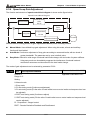
3-2
Chapter 3 Configuration and Wiring
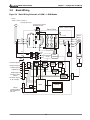
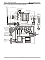
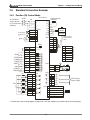
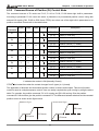
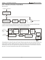
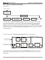
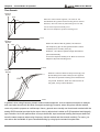
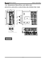
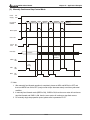
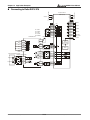
Basic Wiring
Figure 3.4 Basic Wiring Schematic of 100W ~ 1.5kW Models
Power
100W a1.5kW 1-phase or
3-phase 200 a 230V
Connect to external
braking resistor
~
P
Servo Drive
D C
750W~1.5kW models
PRB
60W or 120W
+12V
Servo
Motor
R
U
V
S
T
M
W
PE
L1
+15V
+5V
+3.3V Protection
circuit
+24V
L2
PE
External speed
Current
control
A/D
External torque
GATE
DRIVER
PWM
ENC
Position pulse
CN1
Digital input
A/D
Digital output
CN2
Analog monitor
output
Encoder signal
A, B, Z output
MCU
CN3
Serial
communication
Display
D/A
RS-232/RS-485
/RS-422
© DELTA ELECTRONICS, INC. ALL RIGHTS RESERVED
3-9
4th Edition 2005/11/30, HE03
Chapter 3 Configuration and Wiring
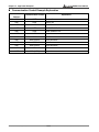
ASDA-A User Manual
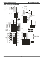
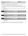
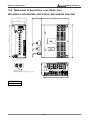
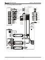
Figure 3.5 Basic Wiring Schematic of 2kW ~ 3kW Models
Power
2kW a3kW
3-phase 200 a 230V
Connect to external
braking resistor
~
N
Servo Drive
P D C
PRB
60W or 120W
+12V
Servo
Motor
R
U
S
T
V
M
W
PE
L1
+15V
+5V
+3.3V
+24V
L2
PE
Protection GATE
circuit
DRIVER
External speed
Current
control
A/D
External torque
PWM
ENC
Position pulse
Digital output
CN1
Digital input
A/D
CN2
Analog monitor
output
Encoder signal
A, B, Z output
MCU
RS-232/RS-485
/RS-422
CN3
Serial
communication
4th Edition 2005/11/30, HE03
Display
D/A
3-10
© DELTA ELECTRONICS, INC. ALL RIGHTS RESERVED
ASDA-A User Manual
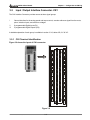
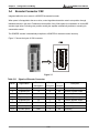
3-3
Chapter 3 Configuration and Wiring
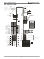
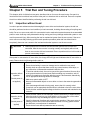
Input / Output Interface Connector -CN1
The CN1 Interface Connector provides access to three signal groups:
i
General interface for the analog speed and torque control, encoder reference signal from the motor,
pulse / direction inputs, and reference voltages.
ii
8 programmable Digital Inputs (DI)
iii
5 programmable Digital Outputs (DO)
A detailed explanation of each group is available in section 3-3-2, tables 3-B, 3-C & 3-D.
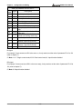
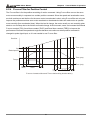
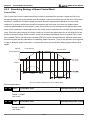
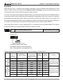
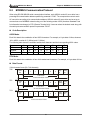
3-3-1 CN1 Terminal Identification
Figure 3.6 shows the layout of CN1 connector:
Figure 3.6
© DELTA ELECTRONICS, INC. ALL RIGHTS RESERVED
3-11
4th Edition 2005/11/30, HE03
Chapter 3 Configuration and Wiring
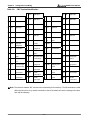
Table 3.A
CN1 Terminal Identification
1
2
DO3-
DO2-
DO1-
DI4-
DO2+
31 DI7DO1+
33 DI5DI1-
35 PULL
11 COM+ Power input
12 GND
Analog input
signal ground
14 NC
(12~24V)
13 GND
No Connection
HI
37 SIGN
39 NC
power
output 1
output 2
17 VDD
18 T_REF Analog torque
Input
20 VCC
+12V power output
(for analog command)
22 /OA
21 OA
23 /OB
Encoder
/Z pulse output
25 OB
Digital input
36 /SIGN
Position sign (Ё)
38 NC
No Connection
40 NC
No Connection
43 /PULSE Pulse input (Ё)
input (Ѐ)
44 GND
45 COM-
VDD(24V) power
ground
47 COM-
Encoder
/B pulse output
34 DI3-
42 V_REF Analog speed
Encoder
A pulse output
Digital input
41 PULSE Pulse input (Ѐ)
Analog input
signal ground
Encoder
/A pulse output
24 /OZ
19 GND
32 DI6-
No Connection
+24V power output
(for external I/O)
Digital input
Position sign (Ѐ)
15 MON2 Analog monitor
16 MON1 Analog monitor
30 DI8-
Pulse applied
Analog input
signal ground
Digital output
Digital input
Digital input
Digital input
28 DO5+
Digital input
Digital output
Digital input
Digital output
No Connection
Digital output
Digital output
26 DO4Digital output
Digital output
29 NC
9
10 DI2-
DO3+
Digital output
7
8
Digital output
27 DO5-
5
6
DO4+
Digital output
3
4
ASDA-A User Manual
Encoder
46 NC
No Connection
48 NC
No Connection
50 OZ
Encoder
VDD(24V) power
ground
B pulse output
signal ground
VDD(24V) power
ground
49 COM-
Analog input
Z pulse output
Note: The terminals marked "NC" must be left unconnected (No Connection). The NC terminals are used
within the servo drive. Any outside connection to the NC terminals will result in damage to the drive
and void the warranty!
4th Edition 2005/11/30, HE03
3-12
© DELTA ELECTRONICS, INC. ALL RIGHTS RESERVED
ASDA-A User Manual
Chapter 3 Configuration and Wiring
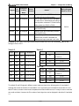
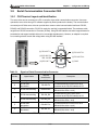
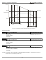
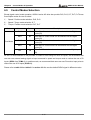
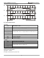
3-3-2 Signals Explanation of Connector CN1
The tables 3.B, 3.C, & 3.D detail the three groups of signals of the CN1 interface. Table 3.B details the
general signals. Table 3.C details the Digital Input (DI) signals and Table 3.D details the Digital Output (DO)
signals. The General Signals are set by the factory and can not be changed, reprogrammed or adjusted. Both
the Digital Input and Digital Output signals can be programmed by the user.
Table 3.B
General Signals
Signal
V_REF
Wiring Diagram
Pin No
Details
42
Motor speed command: -10V to +10V, corresponds to
(Refer to 3-3-3)
Analog
the maximum speed programmed P1-55 Maximum
Signal
Speed Limit (Factory default 3000 RPM).
Input
T_REF
18
Motor torque command: -10V to +10V, corresponds to
C1
C1
-100% to +100% rated torque command.
Analog
MON1
16
The MON1 and MON2 can be assigned drive and
MON2
15
motor parameters that can be monitored via an
C2
analogue voltage.
Monitor
Please reference parameter P0-03 for monitoring
Output
commands and P1-04 / P1-05 for scaling factors.
Output voltage is reference to the power ground.
C3/C4
PULSE
41
The drive can accept two different types of pulse
/PULSE
43
inputs: Open Collector and Line Driver.
Position
SIGN
37
Three different pulse commands can be selected via
Pulse
/SIGN
36
parameter P1-00. Quadrature, CW + CCW pulse &
Pulse / Direction.
Input
PULL HI
35
Should an Open Collector type of pulse be used this
C3
terminal must be lulled high to pin 17.
Position
Pulse
Output
OA
21
The motor encoder signals are available through these
/OA
22
terminals. The encoder output pulse count can be set
OB
25
via parameter P1-46.
/OB
23
OZ
50
/OZ
24
© DELTA ELECTRONICS, INC. ALL RIGHTS RESERVED
3-13
C11/C12
4th Edition 2005/11/30, HE03
Chapter 3 Configuration and Wiring
Signal
VDD
ASDA-A User Manual
Wiring Diagram
Pin No
Details
17
VDD is the +24V source voltage provided by the drive.
(Refer to 3-3-3)
-
Maximum permissible current 500mA.
Power
COM+
11
COM+ is the common voltage rail of the Digital Input
COM-
45
and Digital Output signals. Connect VDD to Com+ for
47
source mode. For external applied power sink mode
49
(+12V to +24V), the positive terminal should be
connected to COM+ and the negative to COM-.
VCC
20
VCC is a +12V power rail provided by the drive. It can
-
be used for the input on an analog speed or torque
command. Maximum permissible current 100mA.
Power
GND
12,13,
The polarity of VCC is with respect to Ground (GND).
19,44
Other
NC
14,29,
38,39,
40,46,
48
See previous note for NC terminals CN1 connector
3.A.
-
The Digital Input (DI) and Digital Output (DO) have factory default settings which correspond to the various
servo drive control modes. (See section 1-5). However, both the DI's and DO's can be programmed
independently to meet the requirements of the user.
Detailed in tables 3.C and 3.D are the DI and DO functions with their corresponding signal name and wiring
schematic. The factory default settings of the DI and DO signals are detailed in tables 3.H and 3.I
All of the Digital Outputs, 1 ~ 5 and their corresponding pin numbers are factory set and nonchangeable,
however, all of the assigned signals and control modes are user changeable. For Example; The alarm
setting DO 5 (pins 28/27) can be assigned to DO 1 (pins 7/6) and vise versa.
4th Edition 2005/11/30, HE03
3-14
© DELTA ELECTRONICS, INC. ALL RIGHTS RESERVED
ASDA-A User Manual
Chapter 3 Configuration and Wiring
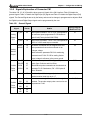
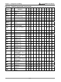
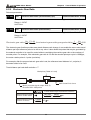
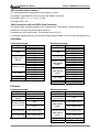
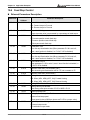
The following tables 3.C and 3.D detail the functions, applicable operational modes, signal name and
relevant wiring schematic of the default DI and DO signals.
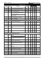
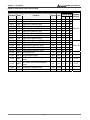
Table 3.C
DO
Signal
SRDY
Digital Output Functions
DO
Assigned
Code Control Mode
01
ALL
Pin No.
+
-
7
6
Wiring Diagram
Details (*1)
(Default)
(Refer to 3-3-3)
SRDY is activated when the servo drive is
ready to run. All fault and alarm conditions, if
present, have been cleared.
SON
02
Not assigned
-
-
SON is activated when control power is
applied the servo drive. The drive may or
may not be ready to run as a fault / alarm
condition may exist.
Servo ON (SON) is "ON" with control power
applied to the servo drive, there may be a
fault condition or not. The servo is not ready
to run. Servo ready (SRDY) is "ON" where
the servo is ready to run, NO fault / alarm
exists. (P2-51 should turn servo ready SRDY
off / on)
ZSPD
03
ALL
5
4
ZSPD is activated when the drive senses the
C5/C6/C7/C8
motor is equal to or below the Zero Speed
Range setting as defined in parameter
P1-38.
For Example, at default ZSPD will be
activated when the drive detects the motor
rotating at speed at or below 10 rpm. ZSPD
will remain activated until the motor speed
increases above 10 RPM.
TSPD
04
ALL
3
2
TSPD is activated once the drive has
detected the motor has reached the Target
Rotation Speed setting as defined in
parameter P1-39. TSPD will remain activated
until the motor speed drops below the Target
Rotation Speed.
© DELTA ELECTRONICS, INC. ALL RIGHTS RESERVED
3-15
4th Edition 2005/11/30, HE03
Chapter 3 Configuration and Wiring
DO
Signal
TPOS
DO
Assigned
Code Control Mode
05
Pt, Pr, Pt-S,
ASDA-A User Manual
Pin No.
Details (*1)
(Default)
+
1
-
Wiring Diagram
(Refer to 3-3-3)
26 1. When the drive is in Pt mode, TPOS will
Pt-T, Pr-S,
be activated when the position error is
Pr-T
equal and below the setting value of
P1-54.
2. When the drive is in Pr mode, TPOS will
be activated when the drive detects that
the position of the motor is in a -P1-54 to
+P1-54 band of the target position. For
Example, at factory default TPOS will
activate once the motor is in -99 pulses
range of the target position, then
deactivate after it reaches +99 pulses
range of the desired position.
TQL
06
Not assigned
-
-
TQL is activated when the drive has detected
that the motor has reached the torques limits
C5/C6/C7/C8
set by either the parameters P1-12 ~ P1-14
of via an external analog voltage.
ALRM
07
ALL
28
27 ALRM is activated when the drive has
detected a fault condition.
BRKR
08
ALL
1
26 BRKR is activated actuation of motor brake.
HOME
09
Pt, Pr
3
2
HOME is activated when the servo drive has
detected that the "HOME" sensor (Digital
Input 24) has been detected and the home
conditions set in parameters P1-47, P1-50,
and P1-51 have been satisfied.
OLW
10
ALL
-
-
OLW is activated when the servo drive has
detected that the motor has reached the
output overload level set by parameter
P1-56.
Footnote *1: The "state" of the output function may be turned ON or OFF as it will be dependant on the
settings of P2-18~P2-22.
Note:
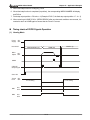
1. PINS 3 & 2 can either be TSPD or HOME dependent upon control mode selected.
2. PINS 1 & 26 are different depending on control mode either BRKR or TPOS.
4th Edition 2005/11/30, HE03
3-16
© DELTA ELECTRONICS, INC. ALL RIGHTS RESERVED
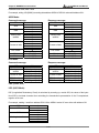
ASDA-A User Manual
Table 3.D
DI Signal
Chapter 3 Configuration and Wiring
Digital Input Functions
DI
Assigned
Control
Code
Mode
Pin No.
Wiring Diagram
Details (*2)
(Default)
(Refer to 3-3-3)
SON
01
ALL
ARST
02
ALL
33
GAINUP
03
ALL
-
CCLR
04
Pt
ZCLAMP
05
ALL
-
When this signal is On and the motor speed
value is lower than the setting value of
P1-38, it is used to lock the motor in the
instant position while ZCLAMP is On.
CMDINV
06
Pr, T, S
-
When this signal is On, the motor is in
reverse rotation.
HOLD
07
Not assigned
CTRG
08
Pr,
Pr-S, Pr-T
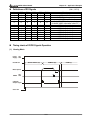
10
When the drive is in Pr mode and CTRG is
activated, the drive will command the motor
to move the stored position which
correspond the POS 0, POS 1, POS 2
settings. Activation is triggered on the rising
edge of the pulse.
TRQLM
09
S, Sz
10
ON indicates the torque limit command is
valid.
SPDLM
10
T, Tz
10
ON indicates the speed limit command is
valid.
POS0
11
Pr, Pr-S, Pr-T
34
POS1
12
8
POS2
13
-
When the Pr Control Mode is selected the 8
stored positions are programmed via a
combination of the POS 0, POS 1, and POS
2 commands. See table 3.E.
SPD0
14
SPD1
15
TCM0
16
TCM1
S-P
9
10
Servo On. Switch servo to "Servo Ready".
Check parameter P2-51.
A number of Faults (Alarms) can be cleared
by activating ARST. Please see table 10-3 for
applicable faults that can be cleared with the
ARST command. However, please
investigate Fault or Alarm if it does not clear
or the fault description warrants closer
inspection of the drive system.
Gain switching
When CCLR is activated the setting is
parameter P2-50 Pulse Clear Mode is
executed.
Internal position control command pause
S, Sz, Pt-S,
Pr-S, S-T
34
34
17
Pt, T, Tz, Pt-T
Pr-T, S-T
18
Pt-S, Pr-S
31
8
8
© DELTA ELECTRONICS, INC. ALL RIGHTS RESERVED
C9/C10
Select the source of speed command:
See table 3.F.
Select the source of torque command:
See table 3.G.
Speed / Position mode switching
OFF: Speed, ON: Position
3-17
4th Edition 2005/11/30, HE03
Chapter 3 Configuration and Wiring
DI Signal
DI
Code
Assigned
Control
Mode
ASDA-A User Manual
Pin No.
Details (*2)
(Default)
S-T
19
S-T
31
Speed / Torque mode switching
OFF: Speed, ON: Torque
T-P
20
Pt-T, Pr-T
31
Torque / Position mode switching
OFF: Torque, ON: Position
EMGS
21
ALL
30
It should be contact “b” and normally ON or a
fault (ALE13) will display.
CWL
22
Pt, Pr, S, T
Sz, Tz
32
Reverse inhibit limit. It should be contact “b”
and normally ON or a fault (ALE14) will
display.
CCWL
23
Pt, Pr, S, T
Sz, Tz
31
Forward inhibit limit. It should be contact “b”
and normally ON or a fault (ALE15) will
display.
ORGP
24
Not assigned
-
When ORGP is activated, the drive will
command the motor to start to search the
reference “Home” sensor.
TLLM
25
Not assigned
-
Reverse operation torque limit (Torque limit
function is valid only when P1-02 is enabled)
TRLM
26
Not assigned
-
Forward operation torque limit (Torque limit
function is valid only when P1-02 is enabled)
SHOM
27
Not assigned
-
When SHOM is activated, the drive will
command the motor to move to “Home”.
INDEX0
28
Not assigned
-
Feed step selection input 0 (bit 0)
INDEX1
29
Not assigned
-
Feed step selection input 1 (bit 1)
INDEX2
30
Not assigned
-
Feed step selection input 2 (bit 2)
INDEX3
31
Not assigned
-
Feed step selection input 3 (bit 3)
INDEX4
32
Not assigned
-
Feed step selection input 4 (bit 4)
MD0
33
Not assigned
-
Feed step mode input 0 (bit 0)
MD1
34
Not assigned
-
Feed step mode input 1 (bit 1)
MDP0
35
Not assigned
-
Manually continuous operation
MDP1
36
Not assigned
-
Manually single step operation
JOGU
37
Not assigned
-
Forward JOG input. When JOGU is
activated, the motor will JOG in forward
direction. [see P4-05]
JOGD
38
Not assigned
-
Reverse JOG input. When JOGD is
activated, the motor will JOG in reverse
direction. [see P4-05]
STEPU
39
Not assigned
-
Step up input. When STEPU is activated, the
motor will run to next position.
STEPD
40
Not assigned
-
Step down input. When STEPD is activated,
the motor will run to previous position.
4th Edition 2005/11/30, HE03
3-18
Wiring Diagram
(Refer to 3-3-3)
C9/C10
© DELTA ELECTRONICS, INC. ALL RIGHTS RESERVED
ASDA-A User Manual
DI Signal
DI
Code
Assigned
Control
Chapter 3 Configuration and Wiring
Pin No.
(Default)
Mode
Wiring Diagram
Details (*2)
(Refer to 3-3-3)
STEPB
41
Not assigned
-
Step back input. When STEPB is activated,
the motor will return to first position.
AUTOR
42
Not assigned
-
Auto run input. When AUTOR is activated,
the motor will run automatically according to
internal position command. For time interval
setting, please see P2-52 to P2-59.
GNUM0
43
Not assigned
-
Electronic gear ratio (Numerator) selection 0
[See P2-60~P2-62]
GNUM1
44
Not assigned
-
Electronic gear ratio (Numerator) selection 1
[See P2-60~P2-62]
INHP
45
Not assigned
-
Pulse inhibit input. When the drive is in
position mode, if INHP is activated, the
external pulse input command is not valid.
C9/C10
Footnote *2: The "state" of the input function may be turned ON or OFF as it will be dependant on the
settings of P2-10~P2-17.
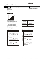
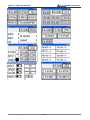
Table 3.E
Table 3.F
POS2
POS1
POS0
Parameter
SPD1
SPD0
Parameter
OFF
OFF
OFF
P1-15, P1-16
OFF
OFF
OFF
OFF
ON
P1-17, P1-18
OFF
ON
P1-09
OFF
ON
OFF
P1-19, P1-20
ON
OFF
P1-10
ON
ON
P1-11
OFF
ON
ON
P1-21, P1-22
ON
OFF
OFF
P1-23, P1-24
TCM1
TCM0
Parameter
ON
OFF
ON
P1-25, P1-26
OFF
OFF
ON
ON
OFF
P1-27, P1-28
OFF
ON
P1-12
ON
ON
ON
P1-29, P1-30
ON
OFF
P1-13
ON
ON
P1-14
S mode: analog input
Sz mode: 0
Table 3.G
T mode: analog input
Tz mode: 0
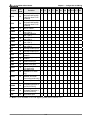
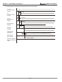
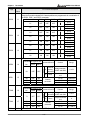
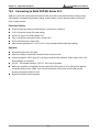
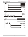
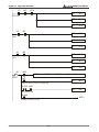
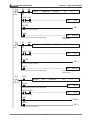
The default DI and DO signals in different control mode are listed in the following table 3.H and table 3.I.
Although the content of the table 3.H and table 3.I do not provide more information than the table 3.C and
table 3.D above, as each control mode is separated and listed in different row, it is easy for user to view and
can avoid confusion. However, the Pin number of each signal can not be displayed in the table 3.H and table
3.I.
© DELTA ELECTRONICS, INC. ALL RIGHTS RESERVED
3-19
4th Edition 2005/11/30, HE03
Chapter 3 Configuration and Wiring
Table 3.H
Signal
ASDA-A User Manual
Default DI signals and Control modes
DI
Function
Code
Pt
Pr
S
T
Sz
Tz Pt-S Pt-T Pr-S Pr-T S-T
SON
01
Servo On
ARST
02
GAINUP
03
CCLR
04
Reset
DI5 DI5 DI5 DI5 DI5 DI5
Gain switching in speed
and position mode
Pulse clear (see P2-50) DI2
DI2 DI2
ZCLAMP
05
CMDINV
06
HOLD
07
CTRG
08
TRQLM
09
SPDLM
10
POS0
11
POS1
12
POS2
13
SPD0
14
SPD1
15
TCM0
16
TCM1
17
S-P
18
S-T
19
T-P
20
EMGS
21
CWL
22
CCWL
23
ORGP
24
DI1 DI1 DI1 DI1 DI1 DI1 DI1 DI1 DI1 DI1 DI1
Low speed CLAMP
Command input reverse
control
Internal position control
command pause
Command triggered
(available in P mode
only)
Torque limit enabled
Speed limit enabled
Position command
selection (1~8)
Position command
selection (1~8)
Position command
selection (1~8)
Speed command
selection (1~4)
Speed command
selection (1~4)
Torque command
selection (1~4)
Torque command
selection (1~4)
Position / Speed mode
switching (OFF: Speed,
ON: Position)
Speed / Torque mode
switching (OFF: Speed,
ON: Torque)
Torque / Position mode
switching (OFF: Torque,
ON: Position)
Emergency stop
(contact b)
Reverse inhibit limit
(contact b)
Forward inhibit limit
(contact b)
Reference “Home”
sensor
4th Edition 2005/11/30, HE03
DI2
DI2 DI2
DI2
DI2
DI2
DI2
DI3
DI3 DI3
DI4
DI4 DI4
DI3
DI3
DI3
DI5
DI3
DI4
DI4
DI4
DI6
DI4
DI3
DI3
DI3
DI3
DI5 DI5
DI4
DI4
DI4
DI4
DI6 DI6
DI7
DI7
DI7
DI7
DI7
DI8 DI8 DI8 DI8 DI8 DI8 DI8 DI8 DI8 DI8 DI8
DI6 DI6 DI6 DI6 DI6 DI6
DI7 DI7 DI7 DI7 DI7 DI7
3-20
© DELTA ELECTRONICS, INC. ALL RIGHTS RESERVED
ASDA-A User Manual
Signal
DI
Code
TLLM
25
TRLM
26
SHOM
27
INDEX0
28
INDEX1
29
INDEX2
30
INDEX3
31
INDEX4
32
MD0
33
MD1
34
MDP0
35
MDP1
36
JOGU
37
JOGD
38
STEPU
39
STEPD
40
STEPB
41
AUTOR
42
GNUM0
43
GNUM1
44
INHP
45
Function
Chapter 3 Configuration and Wiring
Pt
Pr
S
T
Sz
Tz Pt-S Pt-T Pr-S Pr-T S-T
Reverse operation torque
limit (torque limit function
is valid only when P1-02
is enabled)
Forward operation torque
limit (torque limit function
is valid only when P1-02
is enabled)
Move to “Home”
Feed step selection
input 0 (bit 0)
Feed step selection
input 1 (bit 1)
Feed step selection
input 2 (bit 2)
Feed step selection
input 3 (bit 3)
Feed step selection
input 4 (bit 4)
Feed step mode input 0
Feed step mode input 1
Manually continuous
operation
Manually single step
operation
Forward JOG input
Reverse JOG input
Step up input (available
in Pr mode only)
Step down input
(available in Pr mode
only)
Step back input.
(available in internal
auto running mode only)
Auto run input
Electronic gear ratio
(Numerator) selection 0
[see P2-60~P2-62]
Electronic gear ratio
(Numerator) selection 1
[see P2-60~P2-62]
Pulse inhibit input
Note: For Pin numbers of DI1~DI8 signals, please refer to section 3-3-1.
© DELTA ELECTRONICS, INC. ALL RIGHTS RESERVED
3-21
4th Edition 2005/11/30, HE03
Chapter 3 Configuration and Wiring
Table 3.I
ASDA-A User Manual
Default DO signals and Control modes
DO
Signal
Function
Code
Pt
Pr
S
T
Sz
Tz Pt-S Pt-T Pr-S Pr-T S-T
SRDY
01
Servo ready
SON
02
Servo On
ZSPD
03
Zero speed
TSPD
04
Speed reached
TPOS
05
Positioning completed
DO4 DO4
TQL
06
ALRM
07
DO5 DO5 DO5 DO5 DO5 DO5 DO5 DO5 DO5 DO5 DO5
BRKR
08
Reached torques limits
Servo alarm output
(Servo fault)
Electromagnetic brake
DO1 DO1 DO1 DO1 DO1 DO1 DO1 DO1 DO1 DO1 DO1
DO2 DO2 DO2 DO2 DO2 DO2 DO2 DO2 DO2 DO2 DO2
DO3 DO3 DO3 DO3 DO3 DO3 DO3 DO3 DO3
DO4 DO4 DO4 DO4 DO4
DO4 DO4 DO4 DO4
Home completed
DO3 DO3
Output overload
10
OLW
warning
Note: For Pin numbers of DO1~DO5 signals, please refer to section 3-3-1.
09
HOME
3-3-3 User-defined DI and DO signals
If the default DI and DO signals could not be able to fulfill users’ requirements, there are still user-defined DI
and DO signals. The setting method is easy and they are all defined via parameters. The user-defined DI
and DO signals are defined via parameters P2-10 to P2-17 and P2-18 to P2-22.
Please refer to the following Table 3.J for the settings.
Table 3.J
User-defined DI and DO signals
Signal Name
DI
Pin No.
Parameter
DI1-
9
P2-10
DI2-
10
DI3-
Signal Name
Pin No.
Parameter
DO1+
7
P2-18
P2-11
DO1-
6
34
P2-12
DO2+
5
DI4-
8
P2-13
DO2-
4
DI5-
33
P2-14
DO3+
3
DO3-
2
DO
DI6-
32
P2-15
DI7-
31
P2-16
DO4+
1
DI8-
30
P2-17
DO4-
26
DO5+
28
DO5-
27
4th Edition 2005/11/30, HE03
3-22
P2-19
P2-20
P2-21
P2-22
© DELTA ELECTRONICS, INC. ALL RIGHTS RESERVED
ASDA-A User Manual
Chapter 3 Configuration and Wiring
Setting of parameter P2-10 to P2-17:
DI
Code
01
02
Signal
SON
Setting of parameter P2-18 to P2-22:
DO
Code
01
Description
Servo On
Signal
Description
SRDY Servo ready
02
SON
03
ZSPD Zero speed
04
ARST Reset
Gain switching in speed and
GAINUP
position mode
CCLR Pulse clear (see P2-50)
04
TSPD Speed reached
05
ZCLAMP Low speed CLAMP
05
TPOS Positioning completed
06
06
09
CMDINV Command input reverse control
Internal position control command
HOLD
pause
Command triggered (available in P
CTRG
mode only)
TRQLM Torque limit enabled
10
SPDLM Speed limit enabled
10
03
07
08
11
POS0 Position command selection (1~8)
12
POS1 Position command selection (1~8)
13
POS2 Position command selection (1~8)
14
SPD0 Speed command selection (1~3)
15
SPD1 Speed command selection (1~3)
16
TCM0 Torque command selection (1~3)
17
TCM1 Torque command selection (1~3)
Position / Speed mode switching
S-P
(OFF: Speed, ON: Position)
Speed / Torque mode switching
S-T
(OFF: Speed, ON: Torque)
Torque / Position mode switching
T-P
(OFF: Torque, ON: Position)
EMGS Emergency stop (contact b)
18
19
20
21
22
CWL
CCWL Forward inhibit limit (contact b)
24
ORGP Reference “Home” sensor
Reverse operation torque limit
TLLM (Torque limit function is valid only
when P1-02 is enabled)
Forward operation torque limit
TRLM (Torque limit function is valid only
when P1-02 is enabled)
SHOM Move to “Home”
26
27
Reached torques limits
07
ALRM Servo alarm output (Servo fault)
08
BRKR Electromagnetic brake
09
HOME Home completed
OLW
Output overload warning
Reverse inhibit limit (contact b)
23
25
TQL
Servo On
28
INDEX0 Feed step selection input 0 (bit 0)
29
INDEX1 Feed step selection input 1 (bit 1)
30
INDEX2 Feed step selection input 2 (bit 2)
31
INDEX3 Feed step selection input 3 (bit 3)
32
INDEX4 Feed step selection input 4 (bit 4)
© DELTA ELECTRONICS, INC. ALL RIGHTS RESERVED
3-23
4th Edition 2005/11/30, HE03
Chapter 3 Configuration and Wiring
ASDA-A User Manual
Setting of parameter P2-10 to P2-17:
DI
Code
33
Signal
34
Description
MD0
Feed step mode input 0
MD1
Feed step mode input 1
35
MDP0 Manually continuous operation
36
MDP1 Manually single step operation
37
JOGU Forward JOG input
38
39
40
41
42
43
44
45
JOGD Reverse JOG input
Step up input (available in Pr mode
STEPU
only)
Step down input (available in Pr
STEPD
mode only)
Step back input. (available in
STEPB
internal auto running mode only)
AUTOR Auto run input
Electronic gear ratio (Numerator)
GNUM0
selection 0 [see P2-60~P2-62]
Electronic gear ratio (Numerator)
GNUM1
selection 1 [see P2-60~P2-62]
INHP Pulse inhibit input
DI signal:
For example: If user wants to set DI1 to be servo on, it only needs to set the value of parameter P2-10 to 101
(refer to chapter 7).
Note: 11~17: Single control mode;18~20: Dual control mode; 0: Input function disabled
DO signal:
For example: If users want to set DO1 to be servo ready, it only needs to set the value of parameter P2-18 to
101 (refer to chapter 7).
Note: 0: Output function disabled
4th Edition 2005/11/30, HE03
3-24
© DELTA ELECTRONICS, INC. ALL RIGHTS RESERVED
ASDA-A User Manual
Chapter 3 Configuration and Wiring
3-3-4 Wiring Diagrams of I/O Signals (CN1)
The valid voltage range of analog input command in speed and torque mode is -10V ~+10V. The command
value can be set via relevant parameters.
C1: Speed / Torque analog signal input
C2: Analog monitor output (MON1, MON2)
Servo Drive
Servo Drive
Output +8V
1mA max.
42 V-REF
18 (T-REF)
10K
MON1 16
(MON2)(15)
+10V
8K
Approx.
10K
A
13
SG
GND
13
8V full scale
GND
SG
!
There are two kinds of pulse inputs, Line driver input and Open-collector input. Max. input pulse frequency of
Line driver input is 500kpps and max. input pulse frequency of Open-collector input is 200kpps.
C3: Pulse input (Open-collector input)
C4: Pulse input (Line driver)
Servo Drive
VDD
Servo Drive
DC24V
Max. input pulse
frequency is
200kpps
17
35
VDD
Approx.
1K
Pull-hi
/SIGN
36
(43) (/PULSE)
270
SIGN
(PULSE)
COM-
17
DC24V
Max. input pulse
frequency is
500kpps
37
(41)
SIGN
37
(41) (PULSE)
45
SG
Be sure to connect a diode when the drive is applied to inductive load.
(Continuous maximum current: 40mA, Instantaneous peak current: max. 100mA)
© DELTA ELECTRONICS, INC. ALL RIGHTS RESERVED
3-25
4th Edition 2005/11/30, HE03
Chapter 3 Configuration and Wiring
ASDA-A User Manual
C5: Wiring of DO signal, for the use of internal
power supply, general load
C6: Wiring of DO signal, for the use of internal
power supply, inductive load
Servo Drive
Servo Drive
DC24V
DC24V
VDD
17
VDD
DOX: (DOX+, DOX-)
X=1,2,3,4,5
DOX: (DOX+, DOX-)
X=1,2,3,4,5
DO1: ( 7, 6)
DO2: ( 5, 4)
DO3: ( 3, 2)
DO4: ( 1, 26)
DO5: (28, 27)
Ensure the polarity(+
of Diode is correct or
may damage the driv
17
DO1: ( 7, 6)
DO2: ( 5, 4)
DO3: ( 3, 2)
DO4: ( 1, 26)
DO5: (28, 27)
R
DOX-
DOX-
COMCOM45
45
C7: Wiring of DO signal, for the use of external
power supply, general load
C8: Wiring of DO signal, for the use of external
power supply, inductive load
Servo Drive
DOX: (DOX+, DOX-)
X=1,2,3,4,5
Servo Drive
DOX: (DOX+, DOX-)
X=1,2,3,4,5
Do not connect
VDD-COM+
DO1: ( 7, 6)
DO2: ( 5, 4)
DO3: ( 3, 2)
DO4: ( 1, 26)
DO5: (28, 27)
DO1: ( 7, 6)
DO2: ( 5, 4)
DO3: ( 3, 2)
DO4: ( 1, 26)
DO5: (28, 27)
R
DC24V
50mA
Do not connect
VDD-COM+
DC24
DC24V
DOX-
DOX-
Ensure the polarity (+, -)
of the Diode is correct or
it may damage the drive.
!
X=1,2,3,4,5
!
4th Edition 2005/11/30, HE03
3-26
© DELTA ELECTRONICS, INC. ALL RIGHTS RESERVED
ASDA-A User Manual
Chapter 3 Configuration and Wiring
Use a relay or open-collector transistor to input signal.
C9: Wiring of DI signal, for the use of internal
power supply
C10: Wiring of DI signal, for the use of external
power supply
Servo Drive
Servo Drive
Do not connect
VDD-COM+
VDD-COM-
DC24V
VDD
17
R: Approx.
4.7K
11
SON
DC24V
200mA
min.
9
45
TR
Vces
Iceo
< 1.0V
=
<
= 100uA
VDD 17
COM+
COM+
Approx. 5mA
for a transistor
DC24V
SON
R: Approx.
4.7K
11
9
COM-
COM-
C11: Encoder output signal (Line driver)
C12: Encoder output signal (photocoupler)
Servo Drive
OA or OB or OZ
21
25
50
Servo Drive
Max. output
current: 40mA
OA or OB or OZ
21
25
50
Max. output
current: 40mA
100
125
/OA or /OB or /OZ
22
23
24
SG
SG
/OA or /OB or /OZ
22
23
24
AM26CS32 type
© DELTA ELECTRONICS, INC. ALL RIGHTS RESERVED
3-27
High speed
photocoupler
4th Edition 2005/11/30, HE03
Chapter 3 Configuration and Wiring
3-4
ASDA-A User Manual
Encoder Connector CN2
Integrated within the servo motor is a 2500PPR incremental encoder.
When power is first applied to the servo drive, control algorithms detect the motor's rotor position through
imbedded sensors in the motor. Feedback to the amplifier of the UVW signals for commutation is via the ABZ
encoder signal wires. Following rotor position sensing the amplifier automatically switches to encoding for
commutation control.
The 2500PPR encoder is automatically multiplied to 10000PPR for increased control accuracy.
Figure 3.7 shows the layout of CN2 connector:
Figure 3.7
Table 3.K
Signals of Encoder Connector
Terminal
Military
Quick
Identification
Connector
Connector
/Z phase input
/Z
G
A6
Encoder /Z phase output
4
/A phase input
/A
B
A2
Encoder /A phase output
5
A phase input
A
A
A1
Encoder A phase output
7
B phase input
B
C
A3
Encoder B phase output
9
/B phase input
/B
D
A4
Encoder /B phase output
10
Z phase input
Z
F
A5
Encoder Z phase output
14,16
Encoder power
+5V
S
A7
Encoder 5V power
13,15
Encoder power
GND
R
A8
Grounding
PIN No.
Signal Name
2
4th Edition 2005/11/30, HE03
3-28
Description
© DELTA ELECTRONICS, INC. ALL RIGHTS RESERVED
ASDA-A User Manual
3-5
Chapter 3 Configuration and Wiring
Serial Communication Connector CN3
3-5-1 CN3 Terminal Layout and Identification
The servo drive can be connected to a PC or controller via a serial communication connector. Users can
operate the servo drive through PC software supplied by Delta (contact to the dealer). The communication
connector/port of Delta servo drive can provide three common serial communication interfaces: RS-232,
RS-485, and RS-422 connection. RS-232 is mostly be used but is somewhat limited. The maximum cable
length for an RS-232 connection is 15 meters (50 feet). Using RS-485 interface can allow longer distance for
transmission and support multiple drives to be connected simultaneously. However, an adapter is required
for converting electric current and voltage when using RS-485 interface.
CN3
Table 3.L
PIN No.
(6 ) RS- 422 T X-
(5) RS-422 TX+
(4 ) RS- 422 R X/ RS -232 R X
(3) RS -422 RX+
( 2) RS -232 T X
(1) GND
Signals of Serial Communication Connector
Signal Name
Terminal
Description
Identification
1
Grounding
GND
-
2
RS-232 data
transmission
3
RS-422 data receiving
RS-422-RX+
For data receiving of the servo drive
(differential line driver + end)
RS-232 data receiving
RS-232_RX
For data receiving of the servo drive.
Connected to the RS-232 interface of PC.
RS-422 data receiving
RS-422_RX-
For data receiving of the servo drive
(differential line driver - end)
5
RS-422 data
transmission
RS-422-TX+
For data transmission of the servo drive
(differential line driver + end)
6
RS-422 data
transmission
RS-422-TX-
For data transmission of the servo drive
(differential line driver - end)
RS-232-TX
4
For data transmission of the servo drive.
Connected to the RS-232 interface of PC.
Note: For the connection of RS-485, please refer to page 8-2 and 8-3.
© DELTA ELECTRONICS, INC. ALL RIGHTS RESERVED
3-29
4th Edition 2005/11/30, HE03
Chapter 3 Configuration and Wiring
ASDA-A User Manual
3-5-2 Connection between PC and Connector CN3
4th Edition 2005/11/30, HE03
3-30
© DELTA ELECTRONICS, INC. ALL RIGHTS RESERVED
ASDA-A User Manual
3-6
Chapter 3 Configuration and Wiring
Standard Connection Example
3-6-1 Position (Pt) Control Mode
Servo Driv e
MC CB
AC 220 /230V
Si ngle -pha se
or Thre e-ph ase
50/60H z
MC
R
S
T
L1
L2
Pu lse Inpu t
(Line Dri ver )
*1
10V
SI GN
37
/S IGN 36
PU LSE 41
/P ULSE 43
T-R EF 18
13
GN D
P
D
C
CN1
U
V
W
FG
CN2
DC24V
SON
C TRG
T CM0
T CM1
DI2
A RST
DI3
10
34
DI4
8
CWL
DI5
DI6
33
32
C CWL
DI7
E MGS
DI8
31
30
1.5 K
SR DY
1 .5K
ZSPD
1 .5K
24V
HOME
1 .5K
TPOS
1 .5K
ALRM
C N1
S ervo
Motor
Black
En coder
G reen
5
A
4
/A
7
B
9
/B
10
Z
2
/Z
14,1 6 +5 V
13,1 5 GN D
Twisted -pair or
twisted -shield
cable
SG
A Blue
/A Blue/ Black
B Gree n
/B Green /Black
Z Yello w
/Z Yello w/Black
+5V Red
GND Blac k
SG
CN1
A
16
MON 1
12,13,19 GND
15
MON 2
CN1
DO 1+
DO 1DO 2+
DO 2DO 3+
DO 3DO 4+
DO 4DO 5+
DO 5-
Red
Wh ite
7
6
5
4
3
2
1
26
28
27
E nco der Wiring
VDD 1 7
COM+ 11
COM- 4 5,47, 49
DI1
9
R ege nera tive
R esis tor
A
10K
10K
CN1
21
22
25
23
50
24
CN3 6
5
4
3
2
1
OA
/OA
OB
/OB
OZ
/OZ
A p has e pu lse
B p has e pu lse
PG Divi ding
Ratio Output
Z p has e pu lse
RS42 2TRS42 2T+
RS42 2R- & RS2 32_R X
RS42 2R+
RS23 2_TX
RS23 2_GND
*1: Please refer to the C4 wiring diagram on page 3-25. If it is open-collector input, please refer to C3 wiring diagram.
© DELTA ELECTRONICS, INC. ALL RIGHTS RESERVED
3-31
4th Edition 2005/11/30, HE03
Chapter 3 Configuration and Wiring
ASDA-A User Manual
3-6-2 Position (Pr) Control Mode
MC CB
AC 220 /230V
Si ngle -pha se
or Thre e-ph ase
50/60H z
R
S
T
L1
L2
CN1
T- REF
1 0V
G ND
18
13
P
D
C
Red
U
White
V
Black
W
Gree n
FG
C N2
V CC
20
DC 24V
SON
CTRG
P OS0
P OS1
A RST
DI2
DI3
DI4
DI5
DI6
DI7
CWL
CCWL
E MGS
DI8
4 5,47, 49
9
10
34
8
33
1 .5K
ZSPD
2 4V
1 .5K
H OME
1 .5K
T POS
1 .5K
ALRM
4th Edition 2005/11/30, HE03
5
A
4
/A
7
B
9
/B
10
Z
2
/Z
14,16 +5V
13,15 GND
Twiste d-pair o r
twisted -shield
cable
SG
B Gr een
/B Green /Bla ck
SG
C N1
A
16
MON1
12,13,19 GND
15
MON2
C N1
7
6
5
4
3
2
1
26
28
27
A Blu e
/A Blue/ Black
GND B lack
31
30
DO 1+
DO 1DO 2+
DO 2DO 3+
DO 3DO 4+
DO 4DO 5+
DO 5-
Encoder
Z Ye llow
/Z Ye llow/Black
+5V Re d
32
1.5K
SR DY
C N1
17
11
Se rvo
Mo tor
E nco der W iring
VDD
COM+
COMDI1
R egenerative
R esis tor
Servo Drive
MC
A
10K
10K
C N1
21
22
25
23
50
24
CN 3 6
5
4
3
2
1
3-32
OA
/OA
OB
/OB
OZ
/OZ
A p hase pulse
B p hase pulse
PG Dividing
Ratio Output
Z p hase pulse
RS42 2TRS42 2T+
RS42 2R- & RS2 32_R X
RS42 2R+
RS23 2_TX
RS23 2_GN D
© DELTA ELECTRONICS, INC. ALL RIGHTS RESERVED
ASDA-A User Manual
Chapter 3 Configuration and Wiring
3-6-3 Speed Control Mode
MC CB
AC 220 /230V
Si ngle -pha se
or Thre e-ph ase
50/60H z
Se rvo Driv e
MC
R
S
T
L1
L2
P
D
C
U
CN1
10K
10V
10K
V- REF
42
13
GND
T-REF
GND
18
13
V CC
20
R ege nera tive
R esis tor
CN2
DI1
DI2
9
SPD0
DI3
34
SPD1
8
C WL
DI4
DI5
DI6
CC WL
DI7
32
31
EMGS
DI8
30
ARST
1.5K
SR DY
1.5K
ZSPD
1.5K
24V
TSPD
1.5K
BRKR
1.5K
ALR M
C N1
5
A
4
/A
7
B
9
/B
10
Z
2
/Z
14,1 6 +5 V
13,1 5 GN D
En coder
T wisted-p air or
twisted-s hield
ca ble
SG
B Gree n
/B Green /Black
Z Yello w
/Z Yello w/Black
10
+5V Red
GND Blac k
33
SG
CN1
A
MON 1
16
12,13 ,19 GND
MON 2
15
C N1
DO 1+
DO 1DO 2+
DO 2DO 3+
DO 3DO 4+
DO 4DO 5+
DO 5-
A Blue
/A Blue/ Black
E ncoder W iring
SON
TRQLM
Servo
Motor
V
B lack
W
Gree n
FG
DC 24V
VDD 1 7
COM+ 11
COM- 4 5,47, 49
Red
White
7
6
5
4
3
2
1
26
28
27
© DELTA ELECTRONICS, INC. ALL RIGHTS RESERVED
A
10K
10K
CN1
21
22
25
23
50
24
CN 3 6
5
4
3
2
1
3-33
OA
/OA
OB
/OB
OZ
/OZ
A p has e pu lse
B p has e pu lse
P G Di viding
R atio Output
Z p has e pu lse
RS4 22TRS4 22T+
RS4 22R- & RS232_RX
RS4 22R+
RS2 32_TX
RS2 32_GND
4th Edition 2005/11/30, HE03
Chapter 3 Configuration and Wiring
ASDA-A User Manual
3-6-4 Torque Control Mode
MCC B
AC 220 /230V
Si ngle-pha se
or Thre e-ph ase
50/60H z
R
S
T
L1
L2
P
CN1
1 0K
10V
10K
Regene rativ e
Resistor
Se rvo Drive
MC
V- REF
GND
42
13
T-REF
GND
18
13
VCC
20
D
C
Red
U
Whi te
V
Blac k
W
G reen
FG
C N2
DC24V
17
COM+ 11
COM- 45 ,47,49
SON
SPDLM
DI1
DI2
9
10
TCM0
DI3
34
TCM1
ARST
DI4
8
DI5
CWL
DI6
33
32
CCWL
DI7
DI8
E MGS
1.5K
S RDY
1.5K
ZS PD
1.5K
24V
TSPD
1.5K
BRKR
1.5K
ALRM
4th Edition 2005/11/30, HE03
CN 1
5
A
4
/A
7
B
/B
9
10
Z
/Z
2
1 4,16 +5V
1 3,15 GND
Twis ted-pai r or
twis ted-shield
cabl e
SG
A Blue
/A Blue/ B lack
B Green
/B Green /Black
Z Yellow
/Z Yellow/Blac k
+5V Red
GND Black
SG
C N1
A
M ON1
16
12,13, 19 G ND
M ON2
15
31
30
A
1 0K
1 0K
C N1
21
22
25
23
50
24
CN 1
DO1+
DO1DO2+
DO2DO3+
DO3DO4+
Enco der
Encoder Wiring
VDD
Serv o
Mot or
7
6
5
4
3
2
1
DO4- 26
DO5+ 28
DO5- 27
CN3 6
5
4
3
2
1
3-34
OA
/OA
OB
/OB
OZ
/OZ
A ph ase pulse
B phase pulse
PG D ivid ing
Rati o Ou tput
Z ph ase pulse
R S422 TR S422 T+
R S422 R- & R S232 _RX
R S422 R+
R S232 _TX
R S232 _GND
© DELTA ELECTRONICS, INC. ALL RIGHTS RESERVED
ASDA-A User Manual
Chapter 4
Chapter 4 Display and Operation
Display and Operation
This chapter describes the basic operation of the digital keypad and the features it offers.
4-1
Digital Keypad
The digital keypad includes the display panel and function keys. The Figure 4.1 shows all of the features of
the digital keypad and an overview of their functions.
Figure 4.1
MODE key
MODE
SHIFT key
SHIFT
SET
UP arrow key
DOWN arrow key
Charge LED
Name
LCD Display
SET key
Function
The LCD Display (5-digit, 7-step display panel) shows the monitor codes,
parameter settings and operation values of the AC servo drive.
Charge LED
The Charge LED lights to indicate the power is applied to the circuit.
MODE Key
Pressing the MODE key can enter or exit different parameter groups and
setting mode.
SHIFT Key
Pressing the SHIFT key can change the parameter group code. After the
parameter group code is set, users can move the cursor to left and change the
parameter settings (blinking) by pressing the SHIFT key.
UP arrow Key
Pressing the UP arrow key can scroll through the parameter groups, the various
parameter settings in each group and change parameter settings.
DOWN arrow Key
Pressing the DOWN arrow key can scroll through the parameter groups, the
various parameter settings in each group and change parameter settings.
SET Key
Pressing the SET key can select, display and save the parameter groups, the
various parameter settings.
© DELTA ELECTRONICS, INC. ALL RIGHTS RESERVED
4-1
4th Edition 2005/11/30, HE03
Chapter 4 Display and Operation
4-2
ASDA-A User Manual
Display Flowchart
Figure 4.2 Keypad Operation
SHIFT
MODE
Monitor Status
SHIFT
Monitor
Parameter
SHIFT
Basic
Parameter
SHIFT
Extension
Parameter
SHIFT
Communication
Parameter
Diagnosis
Parameter
or
or
SET to display setting value
or
SET
to save setting value
(1) When the power is applied to the AC servo drive, the LCD display will show the monitor display
symbol for approximately one second, then enter into the monitor display mode.
(2) In monitor mode, pressing UP or DOWN arrow key can switch monitor parameter code. At this time,
monitor display symbol will display for approximately one second.
(3) In monitor mode, pressing Mode key can enter into parameter mode, pressing the Shift key can switch
parameter group and pressing UP or DOWN arrow key can change parameter group code.
(4) In parameter mode, system will enter into the setting mode immediately after the Set key is pressed.
The LCD display will display the corresponding setting value of this parameter simultaneously. Then,
users can use UP or DOWN arrow key to change parameter value or press Mode to exit and return
back to the parameter mode.
(5) In setting mode, users can move the cursor to left by pressing the SHIFT key and change the
parameter settings (blinking) by pressing the UP or DOWN arrow key.
(6) After the setting value change is completed, press Set key to save parameter setting or execute
command.
(7) When the parameter setting is completed, LCD display will show the end code “-END-“ and
automatically return back to monitor mode.
4th Edition 2005/11/30, HE03
4-2
© DELTA ELECTRONICS, INC. ALL RIGHTS RESERVED
ASDA-A User Manual
4-3
Chapter 4 Display and Operation
Status Display
4-3-1 Save Setting Display
After the Set key is pressed, LCD display will show the following display messages for approx. one second
according to different status.
Display Message
Description
The setting value is saved correctly.
Read only. Write-protected.
Invalid password or no password input
The setting value is error or input reserve setting value.
Servo system is running and it is unable to input.
This parameter will not be stored in EEPROM.
This parameter is valid after restarting the drive.
4-3-2 Abort Setting Display
Display Message
Description
In parameter mode, press Mode key to abort parameter setting.
In setting mode, pressing Mode key can return back to parameter mode.
After returning back to parameter mode, press Mode key again can abort
parameter setting.
4-3-3 Fault Message Display
Display Message
Description
When the AC servo drive has a fault, LCD display will display “ALEnn”.
“ALE” indicates the alarm and “nn” indicates the alarm code. The display
range of alarm code “nn” is 1 to 22. For the information of fault code,
please refer to parameter P0-01.
4-3-4 Positive/Negative Symbol Setting Display
Display Message
Description
When entering into setting mode, pressing UP or DOWN arrow key can
increase/decrease the display value. SHIFT key is used to change the
selected digit (The selected digit will blink).
© DELTA ELECTRONICS, INC. ALL RIGHTS RESERVED
4-3
4th Edition 2005/11/30, HE03
Chapter 4 Display and Operation
Display Message
ASDA-A User Manual
Description
When the parameter setting is greater than four digits, after the display
value is set, continuously press SHIFT key for many times and then
decimal points in the upper four digits will light. Negative value is
indicated by the lit decimal points in the upper four digits.
If the parameter value is less than five digits, the negative value is
indicated by symbol “Ё”. Reverse rotation is also indicates by symbol
“Ё”.
4-3-5 Monitor Setting Display
When the AC servo drive is applied to power, the LCD display will show the monitor display symbols for
approximately one second and then enter into the monitor display mode. In monitor display mode,
pressing UP or DOWN arrow key can change the monitor state or directly change parameter P0-02 to
specify the monitor status. When the power is applied, the setting value of P0-02 is the default monitor
code. For example, if the setting value of P0-02 is 2 when the power is applied, the C.P monitor symbol
will first display and then the pulse command input pulse number will display after.
Settings of P0-02
0
Display Message
Description
Feedback pulse number of servo
Unit
[pulse]
motor (Absolute value)
1
Feedback rotation number of servo
[rev]
motor (Absolute value)
2
Input pulses of pulse command
3
Rotation number of pulse command
4
Error pulse number of pulse
[pulse]
[rev]
[pulse]
command and feedback pulse
5
Input frequency of pulse command
[kHz]
6
Motor rotation speed
[rpm]
7
Speed input command 1
[V]
8
Speed input command 2
[rpm]
9
Torque input command 1
[V]
10
Torque input command 2
[%]
4th Edition 2005/11/30, HE03
4-4
© DELTA ELECTRONICS, INC. ALL RIGHTS RESERVED
ASDA-A User Manual
Settings of P0-02
Chapter 4 Display and Operation
Display Message
Description
Unit
11
Average Torque
[%]
12
Peak Torque
[%]
13
Main circuit voltage
[V]
14
Ratio of Load/Motor inertia
[times]
15
Feedback pulse number of servo
[pulse]
motor (Relative value)
16
Feedback rotation number of servo
[rev]
motor (Relative value)
The following table lists the display examples of monitor value:
Display Message
Description
Positive value display.
Display value: +1234.
Negative value display (The decimal place is lower than five)
Display value: -1234.
Negative value display (The decimal place is greater than four)
Display value: -12345.
Decimal point display
Display value: 12.34.
© DELTA ELECTRONICS, INC. ALL RIGHTS RESERVED
4-5
4th Edition 2005/11/30, HE03
Chapter 4 Display and Operation
4-4
ASDA-A User Manual
General Function Operation
4-4-1 Error Status Display Operation
After entering the parameter mode P4-00 to P4-04, press Set key to display the corresponding error code
history or press UP arrow key to display the error code of H1 to H5 in order. H1 indicates the most recently
occurred error code, H2 is the previous occurred error code before H1 and so forth. Please refer to the
Figure 4.3. The recently occurred error code is 10.
Figure 4.3
SET
or
4-4-2 JOG Operation
After entering parameter mode P4-05, users can follow the following steps to perform JOG operation
(Please also refer to Figure 4.4).
(1)
(2)
Press the SET key to display the JOG rpm speed. (The default value is 20 rpm).
Press the UP or DOWN arrow keys to increase or decrease the desired JOG speed. (This also can
be undertaken by using the SHIFT key to move the cursor to the desired unit column (the effected
number will flash) then changed using the UP and DOWN arrow keys).
(3)
(4)
Press the SET when the desired JOG speed is displayed. The Servo Drive will display "JOG"
Press the UP or DOWN arrow keys to jog the motor either CCW or CW. The motor will only rotation
while the arrow key is activated.
(5)
To change JOG speed again, press the MODE key. The servo Drive will display "P4 - 05". Press
the SET key and the JOG rpm speed will displayed again. Refer back to #2 and #3 to change
speed.
4th Edition 2005/11/30, HE03
4-6
© DELTA ELECTRONICS, INC. ALL RIGHTS RESERVED
ASDA-A User Manual
Chapter 4 Display and Operation
Figure 4.4
SET
or
or
SET
CW
CCW
4-4-3 Position Learning Operation
Follow the following steps to perform position learning operation (Please also refer to Figure 4.5).
(1)
Activate the internal position learning function (Set P2-30=4).
(2)
After enter into parameter mode P4-05, press Set key and the LED display will show learning
moving speed value. The default setting is 20 rpm.
(3)
Press UP or DOWN arrow key to set the desired moving speed value. In the example shown below,
the value is adjusted to 100rpm.
(4)
Press Set key then JOG o1 will display and enter position learning mode.
(5)
In the position learning mode (display JOGox), pressing UP or DOWN arrow key at any time can
rotate Servo motor in forward or reverse rotation. Servo motor will immediately stop running if
releasing the UP or DOWN arrow key. This operation is only available during Servo system is On
(Servo On).
(6)
After position is selected, press Set key then the display JOGo1 will change to JOGo2. At the same
time, the absolute position of servo motor will be memorized inside of the memory. (P1-17 : rotation
numbers, P1-18 : corresponding remaining pulses)
(7)
In the position learning mode (display JOGox), pressing Shift key can directly change the “x” value
of the display “JOGox” so as to jump rapidly to the particular learning position where should be
modified. There is no position memorized at this time.
© DELTA ELECTRONICS, INC. ALL RIGHTS RESERVED
4-7
4th Edition 2005/11/30, HE03
Chapter 4 Display and Operation
ASDA-A User Manual
Figure 4.5
SET
or
SET
SET or
SHIFT
The learning position and Internal memorized position are listed as below:
Learning Position
Internal Memorized Position
JOGo1
P1-15(Position rotation number), P1-16(Position pulse number)
JOGo2
P1-17(Position rotation number), P1-18(Position pulse number)
JOGo3
P1-19(Position rotation number), P1-20(Position pulse number)
JOGo4
P1-21(Position rotation number), P1-22(Position pulse number)
JOGo5
P1-23(Position rotation number), P1-24(Position pulse number)
JOGo6
P1-25(Position rotation number), P1-26(Position pulse number)
JOGo7
P1-27(Position rotation number), P1-28(Position pulse number)
JOGo8
P1-29(Position rotation number), P1-30(Position pulse number)
4-4-4 DO signal Force Output Diagnosis Operation
The digital output signal can be forced to be ON or OFF. Follow the setting method in Figure 4.6 to enter
into DO signal force output diagnosis operation (OP x) mode. Pressing UP or DOWN arrow key can
change “x” value from 1 to 5 and force digital output signals DO1 to DO5 to be ON or OFF. (Please also
refer to Figure 4.6).
4th Edition 2005/11/30, HE03
4-8
© DELTA ELECTRONICS, INC. ALL RIGHTS RESERVED
ASDA-A User Manual
Chapter 4 Display and Operation
Figure 4.6
SET
Force DO to be ON
Force DO1 to be ON
Force DO2 to be ON
or
Force DO3 to be ON
Force DO4 to be ON
Force DO5 to be ON
4-4-5 DI signal Display Diagnosis Operation
Follow the setting method in Figure 4.7 to enter into DI signal display diagnosis operation mode. According
to the ON and OFF status of external input signal DI1 to DI8, the corresponding signal status will display
on the LED display. When the segment lit and display on the screen, it means that the digital input signal is
ON. (Please also refer to Figure 4.7).
Figure 4.7
SET
DI10 DI9 DI8 DI7 DI6 DI5 DI4 DI3 DI2 DI1
Light: OFF OFF ON ON ON ON ON ON ON ON
© DELTA ELECTRONICS, INC. ALL RIGHTS RESERVED
4-9
4th Edition 2005/11/30, HE03
Chapter 4 Display and Operation
ASDA-A User Manual
4-4-6 DO signal Display Diagnosis Operation
Follow the setting method in Figure 4.8 to enter into DO signal display diagnosis operation mode.
According to the ON and OFF status of digital output signals DO1 to DO5, the corresponding signal status
will display on the LED display. When the segment lit and display on the screen, it means that the digital
input signal is ON. (Please also refer to Figure 4.8)
Figure 4.8
SET
DO10 DO9 DO8
DO5DO4 DO3 DO2 DO1
Light: OFF OFF OFF OFF OFF ON ON ON ON ON
4th Edition 2005/11/30, HE03
4-10
© DELTA ELECTRONICS, INC. ALL RIGHTS RESERVED
ASDA-A User Manual
Chapter 5
Chapter 5 Trial Run and Tuning Procedure
Trial Run and Tuning Procedure
This chapter, which is divided into two parts, describes trial run for servo drive and motor. One part is to
introduce the trial run without load, and the other part is to introduce trial run with load. Ensure to complete
the trial run without load first before performing the trial run with load.
5-1
Inspection without Load
In order to prevent accidents and avoid damaging the servo drive and mechanical system, the trial run
should be performed under no load condition (no load connected, including disconnecting all couplings and
belts). Do not run servo motor while it is connected to load or mechanical system because the unassembled
parts on motor shaft may easily disassemble during running and it may damage mechanical system or even
result in personnel injury. After removing the load or mechanical system from the servo motor, if the servo
motor can runs normally following up the normal operation procedure (when trial run without load is
completed), then user can connect to the load and mechanical system to run the servo motor.
CAUTION
zPlease
perform trial run without load first and then perform trial run with load
connected. After the servo motor is running normally and regularly without load,
then run servo motor with load connected. Ensure to perform trial run in this order to
prevent unnecessary danger.
After power in connected to AC servo drive, the charge LED will light and it indicates that AC servo drive is
ready. Please check the followings before trial run:
1. Ensure that all wiring terminals are correctly insulated.
2. Ensure that all wiring is correct or damage and or malfunction may result.
3. Visually check to ensure that there are not any unused screws, metal strips, or
any conductive or inflammable materials inside the drive.
4. To avoid an electric shock, be sure to connect the ground terminal of servo drive
to the ground terminal of control panel. Before making any connection, wait 10
Inspection before
minutes for capacitors to discharge after the power is disconnected, alternatively,
operation
use an appropriate discharge device to discharge.
(Control power is 5. Make sure control switch is OFF.
not applied)
6. Never put inflammable objects on servo drive or close to the external regenerative
resistor.
7. If the electromagnetic brake is being used, ensure that it is correctly wired.
8. If required, use an appropriate electrical filter to eliminate noise to the servo drive.
9. Ensure that the external applied voltage to the drive is correct and matched to the
controller.
1. Ensure that the cables are not damaged, stressed excessively or loaded heavily.
When the motor is running, pay close attention on the connection of the cables
and notice that if they are damaged, frayed or over extended.
operation
2. Check for abnormal vibrations and sounds during operation. If the servo motor is
(Control power is
vibrating or there are unusual noises while the motor is running, please contact
the distributor or manufacturer for assistance.
applied)
3. Ensure that all user defined parameters are set correctly.
Inspection during
© DELTA ELECTRONICS, INC. ALL RIGHTS RESERVED
5-1
4th Edition 2005/11/30, HE03
Chapter 5 Trial Run and Tuning Procedure
ASDA-A User Manual
Inspection during 4. Reset parameters when the servo drive is off. Otherwise, it may result in
malfunction.
operation
5. Ensure correct operation when using a relay and request assistance should there
(Control power is
be any unusual noises.
6.
Check for abnormal conditions of the power indicators and LED display.
applied)
4th Edition 2005/11/30, HE03
5-2
© DELTA ELECTRONICS, INC. ALL RIGHTS RESERVED
ASDA-A User Manual
5-2
Chapter 5 Trial Run and Tuning Procedure
Applying Power to the Drive
Users please observe the following steps when applying power supply to the servo drive.
1. Please check and confirm the wiring connection between the drive and motor is correct.
1) Terminal U, V, W and FG (frame ground) must connect to Red, White, Black and Green cables
separately (U: Red, V: White, W: Black, FG: Green). If not connect to the specified cable and
terminal, then the drive cannot control motor. The motor grounding lead, FG must connect to
grounding terminal. For more information of cables, please refer to section 3-1.
2) Ensure to connect encoder cable to CN2 connector correctly. If users only desire to execute JOG
operation, it is not necessary to make any connection to CN1 and CN3 connector. For more
information of the connection of CN2 connector, please refer to Section 3-1 and 3-4.
CAUTION
zDo
not connect the AC input power (R, S, T) to the U, V, W output terminals. This
will damage the AC servo drive.
2. Main circuit wiring
Connect power to the AC servo. For three-phase input power connection and single-phase input power
connection, please refer to Section 3-1-3.
3. Turn the Power On
The Power includes control circuit power (L1, L2) and main circuit power (R, S, T). When the power is
on, the normal display should be shown as the following figure:
As the default settings of digital input signal, DI6, DI7 and DI8 are Reverse Inhibit Limit (CWL), Forward
Inhibit Limit (CCWL) and Emergency Stop (EMGS) respectively, if need be, the user can change the
settings by using parameters P2-15 to P2-17 freely. When the setting value of parameters P2-15 to
P2-17 is 0, it indicates the function of this DI signal is disabled. For more information of parameters
P2-15 to P2-17, please refer to Chapter 7 “Parameters”.
If the parameter P0-02 is set as motor speed (06), the normal display should be shown as the following
figure:
If there is no text or character displayed on the LED display, please check if the voltage of the control
circuit terminal (L1and L2) is over low.
1) When display shows:
© DELTA ELECTRONICS, INC. ALL RIGHTS RESERVED
5-3
4th Edition 2005/11/30, HE03
Chapter 5 Trial Run and Tuning Procedure
ASDA-A User Manual
Over voltage:
The main circuit voltage has exceeded its maximum allowable value or input power is error (Incorrect
power input).
Corrective Actions:
Use voltmeter to check whether the input voltage falls within the rated input voltage.
Use voltmeter to check whether the input voltage is within the specified limit.
2) When display shows:
Encoder error:
Check if the wiring is correct. Check if the encoder wiring of servo motor is loose or not.
Corrective Actions:
Check if the user performs wiring recommended in the user manual.
Examine the encoder connector
Inspect whether wire is loose or not.
Check if the encoder is damaged.
3) When display shows:
Emergency stop activated:
Please check if any of digital inputs DI1~DI8 signal is set to “Emergency Stop” (EMGS).
Corrective Actions:
If it is no need to use “Emergency Stop (EMGS)” as input signal, it only needs to confirm that if all
of the digital inputs DI1~DI8 are not set to “Emergency Stop (EMGS)”. (The setting value of
parameter P2-10 to P2-17 is not set to 21.)
If it is necessary to use “Emergency Stop (EMGS)” as input signal, it only needs to confirm that
which of digital inputs DI1~DI8 is set to “Emergency Stop (EMGS)” and check if the digital input
signal is ON (It should be ON).
4th Edition 2005/11/30, HE03
5-4
© DELTA ELECTRONICS, INC. ALL RIGHTS RESERVED
ASDA-A User Manual
Chapter 5 Trial Run and Tuning Procedure
4) When display shows:
Reverse limit switch error:
Please check if any of digital inputs DI1~DI8 signal is set to “Reverse inhibit limit (CWL)” and check if
the signal is ON or not.
Corrective Actions:
If it is no need to use “Reverse inhibit limit (CWL)” as input signal, it only needs to confirm that if all
of the digital inputs DI1~DI8 are not set to “Reverse inhibit limit (CWL)”. (The setting value of
parameter P2-10 to P2-17 is not set to 22.)
If it is necessary to use “Reverse inhibit limit (CWL)” as input signal, it only needs to confirm that
which of digital inputs DI1~DI8 is set to “Reverse inhibit limit (CWL)” and check if the digital input
signal is ON (It should be ON).
5) When display shows:
Forward limit switch error:
Please check if any of digital inputs DI1~DI8 signal is set to “Forward inhibit limit (CCWL)” and check if
the signal is ON or not.
Corrective Actions:
If it is no need to use “Forward inhibit limit (CCWL)” as input signal, it only needs to confirm that if
all of the digital inputs DI1~DI8 are not set to “Forward inhibit limit (CCWL)”. (The setting value of
parameter P2-10 to P2-17 is not set to 23.)
If it is necessary to use “Forward inhibit limit (CCWL)” as input signal, it only needs to confirm that
which of digital inputs DI1~DI8 is set to “Forward inhibit limit (CCWL)” and check if the digital input
signal is ON (It should be ON).
If the “
” show on the display and “digital input 1” is set to Servo On (SON), it indicates that
Servo on (SON) function is enabled.
6) When display shows:
© DELTA ELECTRONICS, INC. ALL RIGHTS RESERVED
5-5
4th Edition 2005/11/30, HE03
Chapter 5 Trial Run and Tuning Procedure
ASDA-A User Manual
Overcurrent:
Corrective Actions:
Check the wiring connections between drive and motor.
Check if the circuit of wire is closed.
Repair the short-circuited and avoid metal conductor being exposed.
7) When display shows:
Undervoltage:
Corrective Actions:
Check whether the wiring of main circuit input voltage is normal.
Use voltmeter to check whether input voltage of main circuit is normal.
Use voltmeter to check whether the input voltage is within the specified specification.
Note: If there are any unknown fault codes and abnormal display when applying power to the drive or
servo on is activated (without giving any command), please inform the distributor for assistance.
4th Edition 2005/11/30, HE03
5-6
© DELTA ELECTRONICS, INC. ALL RIGHTS RESERVED
ASDA-A User Manual
5-3
Chapter 5 Trial Run and Tuning Procedure
JOG Trial Run without Load
It is very convenient to use JOG trial run without load because it can save the wiring. For safety, it is
recommended to set JOG speed at low speed. Please refer to the following steps to perform JOG trial run
without load.
STEP 1: Turn the drive ON through software. The setting value of parameter P2-30 should be set to 1 (servo
on).
STEP 2: Set parameter P4-05 as JOG speed (unit: rpm). After the desired JOG speed is set, and then press
SET key, the drive will enter into JOG operation mode automatically.
STEP 3: When pressing MODE key, it can exit JOG operation mode.
In the example below, the JOG speed is adjusted from 20rpm (Default setting) to 100rpm.
SE T
Pre ss
key : Servo moto r wi l l run i n C C W dir ectio n.
After rel ea sin g the Up key, the moto r wi ll stop r unn ing .
Pre ss
key : Servo moto r wi l l run i n C W d irection .
Face the servo motor shaft
SE T
CCW (Counterclockw ise): Reve rse running
CW (Clockwise): Forward runnin g
CCW
CW
Spee d
0
P ress
Release
Press
C CW
If the servo motor doe s not rotate , plea se ch eck if the w iring of
U, V, W terminals and enco der is corre ct or not.
If the servo motor does not rotate p roperly, please check if the
phase of U, V, W cables is connected correctly.
© DELTA ELECTRONICS, INC. ALL RIGHTS RESERVED
5-7
4th Edition 2005/11/30, HE03
Chapter 5 Trial Run and Tuning Procedure
5-4
ASDA-A User Manual
Speed Trial Run without Load
Before speed trial run, fix and secure the motor as possible to avoid the danger from the
reacting force when motor speed changes.
STEP 1Κ
Set the value of parameter P1-01 to 02 and it is speed (S) control mode. After selecting the operation mode
as speed (S) control mode, please restart the drive and the setting would be valid.
STEP 2Κ
In speed control mode, the necessary DI setting is listed as follows:
Digital Input
Parameter Setting
Value
Sign
Function Description
CN1 PIN No.
DI1
P2-10=101
SON
Servo On
DI1-=9
DI2
P2-11=109
TRQLM
Torque limit enabled
DI2-=10
DI3
P2-12=114
SPD0
Speed command selection
DI3-=34
DI4
P2-13=115
SPD1
Speed command selection
DI4-=8
DI5
P2-14=102
ARST
Reset
DI5-=33
DI6
P2-15=0
Disabled
This DI function is disabled
-
DI7
P2-16=0
Disabled
This DI function is disabled
-
DI8
P2-17=0
Disabled
This DI function is disabled
-
In the above table, the functions of reverse inhibit limit (DI6), forward inhibit limit (DI7) and emergency stop
(DI8) are disabled, i.e. the setting value of parameters P2-15 to P2-17 is set to 0 (Disabled). All the digital
inputs of Delta ASDA-A series are user-defined, and the user can set the DI signals freely. Ensure to refer to
the definitions of DI signals before defining them.
If alarm code display, the user can restart the drive or set DI5 to be ON to clear the fault. Please refer to
section 5-2.
The speed command is selected by SPD0, SPD1. Please refer to the following table:
Speed
DI signal of CN1
Command No.
SPD1
SPD0
S1
0
0
S2
0
1
S3
1
0
S4
1
1
Command Source
Content
External analog
Voltage between
command
V-REF and GND
Internal parameter
Range
+/-10V
P1-09
0~5000rpm
P1-10
0~5000rpm
P1-11
0~5000rpm
0: indicates OFF (Normally Open)
1: indicates ON (Normally Closed)
4th Edition 2005/11/30, HE03
5-8
© DELTA ELECTRONICS, INC. ALL RIGHTS RESERVED
ASDA-A User Manual
Chapter 5 Trial Run and Tuning Procedure
The settings of speed command:
P1-09 is set to 3000
Input value command
Rotation direction
P1-10 is set to 100
+
CW
P1-11 is set to -3000
-
CCW
STEP 3Κ
(1)
The user can use DI1 to activate the servo drive (Servo ON).
(2)
If DI3 (SPD0) and DI4 (SPD1) are OFF both, it is S1 command. At this time, the motor is operating
according to external analog command.
(3)
If only DI3 is ON (SPD0), it indicates S2 command (P1-09 is set to 3000) is selected, and the motor
speed is 3000rpm at this time.
(4)
If only DI4 is ON (SPD1), it indicates S3 command (P1-10 is set to 100) is selected, and the motor
speed is 100rpm at this time.
(5)
If DI3 (SPD0) and DI4 (SPD1) are ON both, it indicates S4 command (P1-11 is set to -3000) is
selected, and the motor speed is -3000rpm at this time.
(6)
Repeat the action of (3), (4), (5).
(7)
When the motor is stopping, set DI to be OFF (Servo OFF).
© DELTA ELECTRONICS, INC. ALL RIGHTS RESERVED
5-9
4th Edition 2005/11/30, HE03
Chapter 5 Trial Run and Tuning Procedure
5-5
ASDA-A User Manual
Position Trial Run without Load
Before position trial run, fix and secure the motor as possible to avoid the danger from the
reacting force when the motor speed changes.
STEP 1Κ
Set the value of parameter P1-01 to 01 and it is position (Pr) control mode. After selecting the operation
mode as position (Pr) control mode, please restart the drive and the setting would be valid.
STEP 2Κ
In position control mode, the necessary DI setting is listed as follows:
Digital Input
Parameter Setting
Value
Sign
Function Description
CN1 PIN No.
DI1
P2-10=101
SON
Servo On
DI1-=9
DI2
P2-11=108
CTRG
Command trigged
DI2-=10
DI3
P2-12=111
POS0
Position command selection
DI3-=34
DI4
P2-13=112
POS1
Position command selection
DI4-=8
DI5
P2-14=102
ARST
Reset
DI5-=33
DI6
P2-15=0
Disabled
This DI function is disabled
-
DI7
P2-16=0
Disabled
This DI function is disabled
-
DI8
P2-17=0
Disabled
This DI function is disabled
-
In the above table, the functions of reverse inhibit limit (DI6), forward inhibit limit (DI7) and emergency stop
(DI8) are disabled, i.e. the setting value of parameters P2-15 to P2-17 is set to 0 (Disabled). All the digital
inputs of Delta ASDA-A series are user-defined, and the user can set the DI signals freely. Ensure to refer to
the definitions of DI signals before defining them.
If alarm code display, the user can restart the drive or set DI5 to be ON to clear the fault. Please refer to
section 5-2.
For the information of wiring diagram, please refer to Section 3-6-2 (Wiring of position (Pr) control mode).
Because POS2 is not the default DI, therefore, the user needs to change the value of parameter P2-14 to
113.
4th Edition 2005/11/30, HE03
5-10
© DELTA ELECTRONICS, INC. ALL RIGHTS RESERVED
ASDA-A User Manual
Chapter 5 Trial Run and Tuning Procedure
The relationship of position command (1~8) and POS0 ~ POS2 is listed as the table below:
Position
Command
Internal
Position 1
Internal
Position 2
Internal
Position 3
Internal
Position 4
Internal
Position 5
Internal
Position 6
Internal
Position 7
Internal
Position 8
POS2
POS1
POS0
0
0
0
0
0
1
0
1
0
0
1
1
1
0
0
1
0
1
1
1
0
1
1
1
CTRG Parameters
P1-15
P1-16
P1-17
P1-18
P1-19
P1-20
P1-21
P1-22
P1-23
P1-24
P1-25
P1-26
P1-27
P1-28
P1-29
P1-30
Moving Speed
Description
Register
P2-36 (V1)
P2-37 (V2)
P2-38 (V3)
P2-39 (V4)
P2-40 (V5)
P2-41 (V6)
P2-42 (V7)
P2-43 (V8)
Rotation No. (+/- 30000)
Pulse No. (+/- max cnt)
Rotation No. (+/- 30000)
Pulse No. (+/- max cnt)
Rotation No. (+/- 30000)
Pulse No. (+/- max cnt)
Rotation No. (+/- 30000)
Pulse No. (+/- max cnt)
Rotation No. (+/- 30000)
Pulse No. (+/- max cnt)
Rotation No. (+/- 30000)
Pulse No. (+/- max cnt)
Rotation No. (+/- 30000)
Pulse No. (+/- max cnt)
Rotation No. (+/- 30000)
Pulse No. (+/- max cnt)
0: indicates OFF (Normally Open)
1: indicates ON (Normally Closed)
The user can set the value of these 8 groups of commands (P1-15 ~ P1-30) freely. The command can be
absolute position command (P1-34 =0) or relative position command (P1-34 =1).
For example:
Set P1-33 to 1 (Absolute position command)
(The new setting will be valid after the drive is restarted)
Set P1-15 to 1 (rotation number)
Set P1-16 to 0 (pulse number)
The command of internal position 1: P1-15 Rotation No. + P1-16 Pulse No.
Set P1-17 to 10 (rotation number)
Set P1-18 to 0 (pulse number)
The command of internal position 2: P1-17 Rotation No. + P1-18 Pulse No.
Set P1-19 to -10 (rotation number)
Set P1-20 to 0 (pulse number)
The command of internal position 3: P1-19 Rotation No. + P1-20 Pulse No.
Set P1-21 to 100 (rotation number)
Set P1-22 to 0 (pulse number)
The command of internal position 4: P1-21 Rotation No. + P1-22 Pulse No.
© DELTA ELECTRONICS, INC. ALL RIGHTS RESERVED
5-11
4th Edition 2005/11/30, HE03
Chapter 5 Trial Run and Tuning Procedure
ASDA-A User Manual
Set P1-23 to -1000 (rotation number)
Set P1-24 to 0 (pulse number)
The command of internal position 5: P1-23 Rotation No. + P1-24 Pulse No.
Set P1-25 to 0 (rotation number)
Set P1-26 to 100 (pulse number)
The command of internal position 6: P1-25 Rotation No. + P1-26 Pulse No.
Set P1-27 to 0 (rotation number)
Set P1-28 to 1000 (pulse number)
The command of internal position 7: P1-27 Rotation No. + P1-28 Pulse No.
Set P1-29 to -10 (rotation number)
Set P1-30 to 2500 (pulse number)
The command of internal position 8: P1-29 Rotation No. + P1-30 Pulse No.
Input command Rotation direction
+
CW
-
CCW
STEP 3Κ
(1)
The user can use DI1 to activate the servo drive (Servo ON).
(2)
Set DI2 (CTRG) to be ON, it indicates the command of internal position 1 (P1-15 Rotation No. +
P1-16 Pulse No.) 1 turn is selected, and the motor has rotated one turn at this time.
(3)
Set DI3 (POS0) to be ON first and then activate DI2 (CTRG) to be ON, it indicates the command of
internal position 2 (P1-17 Rotation No. + P1-18 Pulse No.)10 turn is selected, and the motor has
rotated ten turns.
(4)
Set DI3 (POS0), DI4 (POS1) and DI5 (POS2) to be ON first and then activate DI2 (CTRG) to be ON,
it indicates the command of internal position 8 (P1-29 Rotation No. + P1-30 Pulse No.)10.25turn is
selected, and the motor has rotated 10.25 turns.
(5)
If DI3 (SPD0) and DI4 (SPD1) are ON both, it indicates S4 command (P1-11 is set to -3000) is
selected, and the motor speed is -3000rpm at this time.
(6)
Repeat the action of (3), (4), (5).
(7)
When the motor is stopping, set DI to be OFF (Servo OFF).
4th Edition 2005/11/30, HE03
5-12
© DELTA ELECTRONICS, INC. ALL RIGHTS RESERVED
ASDA-A User Manual
5-6
Chapter 5 Trial Run and Tuning Procedure
Tuning Procedure
Estimate the ratio of Load Inertia to Servo Motor Inertia (J_load /J_motor): JOG Mode
1.
After wiring is completed, when power in connected to the AC servo drive, the
right side display will show on the LCD display.
2.
Press MODE key to enter into parameter mode.
3.
Press SHIFT key twice to select parameter group.
4.
Press UP key to view each parameter and select parameter P2-30.
5.
Press SET key to display the parameter value as shown on the right side.
6.
Select parameter value 1. Use UP key to cycle through the available settings.
7.
Press SET key to write parameter value to the drive, and the right side display
will show on the LCD display.
8.
At this time, the servo drive is ON and the right side display will appear next.
9.
Press DOWN key three times to select the ratio of Load Inertia to Servo Motor
Inertia (J_load /J_motor).
10. Display the current ratio of Load Inertia to Servo Motor Inertia (J_load /J_motor).
(5.0 is default setting.)
11. Press MODE key to select parameter mode.
12. Press SHIFT key twice to select parameter group.
13. Press UP key to select user parameter P4-05.
14. Press SET key and JOG speed 20rpm will be displayed. Press UP and DOWN
key to increase and decrease JOG speed. To press SHIFT key one time can add
one digit number.
15. Select desired JOG speed, press SET key and it will show the right side display.
16. Pressing UP key is forward rotation and pressing DOWN key is reverse rotation.
17. Execute JOG operation in low speed first. After the machine is running smoothly, then execute JOG
operation in high speed.
18. The ratio of Load Inertia to Servo Motor Inertia (J_load /J_motor) cannot be shown in the display of
JOG parameter P4-05 operation. Please press MODE key twice continuously, and the user can see
the ratio of Load Inertia to Servo Motor Inertia (J_load /J_motor). Then, execute JOG operation again,
press MODE key once and press SET key twice to view the display on the keypad. Check if the value
of J_load /J_motor is adjusted to a fixed value and displayed on the keypad after acceleration and
deceleration repeatedly.
© DELTA ELECTRONICS, INC. ALL RIGHTS RESERVED
5-13
4th Edition 2005/11/30, HE03
Chapter 5 Trial Run and Tuning Procedure
ASDA-A User Manual
5-6-1 Tuning Flowchart
Run without load confirmed OK
If tune the drive
at the first time ?
NO
YES
Removed from the control of the host (external)
controller, perform trial run and estimate the
value of (J_load /J_motor)
Manual Mode
Easy Mode
If the value of (J_load / J_motor) is estimated
incorrectly, the optimum gain can not be adjusted.
AutoMode
Connect to the host (external) controller.
Please pay close attention on the wiring
of CN1 connector. The user can power on
the drive and use parameter P4-07 and
P4-09 to test and check the status of input
and output signal.
(1) Must understand the customer specifications and
what the customer really needs.
(2) Can use P2-23 and P2-24 to suppress the resonance
of mechanical system.
Use the selected tuning mode to
adjust the gain and improve the
drive performance.
OK
4th Edition 2005/11/30, HE03
5-14
© DELTA ELECTRONICS, INC. ALL RIGHTS RESERVED
ASDA-A User Manual
Chapter 5 Trial Run and Tuning Procedure
5-6-2 Load Inertia Estimation Flowchart
Make s ure the power of
Ser v o drive is OFF
Conne ct Motor to the
Mec hanical s ystem
Powe r on Ser vo Driv e
Whe n P0-02 is set to 14, the display will show the rati o of
Load i nertia to Motor inertia ( J _load / J _motor )
I f P2- 32 is set to 0, it is Manual m ode
Set P2-32 t o 1, forc e the dr ive
to be Ser vo On.
YE S
D ecr eas e the se tting va lue of
P2-00. Set the v alue of P2-06
and P2- 00 to th e same value
If ther e is
r es onance noise ?
NO
Enter P4-05 JO G oper ation mode
Set JOG sp eed as 2 0RPM
Press Up ( CCW) or Down (CW)
ke y to perfor m JO G oper ation
Check if co nstant
ope ration is smooth
NO
Check Mechani cal Syst em
YES
Se t higher JOG sp eed > 200RPM
Make the mec hanical sys tem accelerate
and decelerat e alternately
View the display, ch ec k if the ratio of l oad i nertia to motor i nertia (J _load / J_motor)
bec ome a fixed value after the motor acc elerates a nd decelerates al ternately many
time s and then decide the gain adjustment method.
Note:
If the user can not view the ratio of load inertia to motor inertia (J_load / J_motor)
under JOG operatio n ( P4-05), pres s MODE key twice and then the ratio of load
inerti a to motor inertia (J_load / J_motor ) will show on the dis play. If the user desire
to per form J OG ope ration a gain, pleas e pr ess MODE key - -> SET key - -> SET key.
© DELTA ELECTRONICS, INC. ALL RIGHTS RESERVED
5-15
4th Edition 2005/11/30, HE03
Chapter 5 Trial Run and Tuning Procedure
ASDA-A User Manual
5-6-3 Easy Mode Tuning Flowchart
P2-31 Auto and Easy Mode Selection (Default setting: A=4)
A
B
not used
In Easy Mode, the value “A” indicates the stiffness setting. When the setting value is higher, the control
stiffness is also higher
Adjust P2-31: Increase the setting value of P2-31. Increase the value “A” to add the control stiffness or
reduce the noise.
Adjust P2-25: According to the setting value of P2-31 add and adjust the control stiffness.
Continuously adjust until the satisfactory performance is achieved, and then the tuning is completed.
Servo off, and then S ervo on
afte r s etting P2-32 to 1.
When P0-02 is set to 14, the displa y will s how the rati o of
Load inertia to Motor i nertia ( J_load / J_motor)
R eceive F WD. a nd REV. and Accel. an d Decel . Contr ol
command from t he host (extern al) controll er.
M ake the serv o dr ive run F WD. and RE V. alter nately
and perform Acc el. and Decel . operati on r epe atedly.
1. Incr ease P2-3 1 value A to reduc e noise and
refer to Table 5.A to set P2- 00 and P2-25.
2. If the u ser do not wan t to dec rease the
value o f P2-31 value A, the user can use
P2-23 and P2- 24 to s uppress the res onance
of mec hanical sys tem .
YES
If ther e is
r es onanc e noise ?
NO
T he s atisfactory
performance is achieved.
YES
Tuni ng is
Complete
NO
The value o f fix ed i nertia
sho wed on the dis play > 15 mult iple
of roto r inertia
YE S
NO
Inc rease P2-31 value A to 1~9 to
add the control stiffness or reduce
noi se.
Inc re ase P2- 31 valu e A to A ~F to
add th e contr ol stiffn ess or r educe
noi se.
Ple ase refe r to Tab le 5.A t o
s et P2-0 0 and P 2-25.
4th Edition 2005/11/30, HE03
5-16
© DELTA ELECTRONICS, INC. ALL RIGHTS RESERVED
ASDA-A User Manual
Chapter 5 Trial Run and Tuning Procedure
Table 5.A Stiffness Setting in Easy Mode (P2-31 value “A”) and the setting of P2-00, P2-25
Level
(P2-31
High
Responsiveness
Level
Medium
Responsiveness
Level
Low
Responsiveness
Level
Value A)
Load Range
(J_load /J_motor)
Max. Load
Corresponding
Responsiveness
KPP
NLP
(P2-00)
(P2-25)
1
50~100
5Hz
5
50
2
30~50
8Hz
8
31
3
20~30
11Hz
11
33
4
16~20
15Hz
15
16
5
12~16
20Hz
20
12
6
8~12
27Hz
27
9
7
5~8
40Hz
40
6
8
2~5
60Hz
60
4
9
0~2
115Hz
115
2
A
0~2
127Hz
127
1
B
2~8
103Hz
103
2
C
8~15
76Hz
76
3
D
15~25
62Hz
62
4
E
25~50
45Hz
45
5
F
50~100
36Hz
36
6
Remark
The setting of P2-00
and P2-25 must be
inputted manually
The setting of P2-00
and P2-25 must be
inputted manually
The setting of P2-00
and P2-25 must be
© DELTA ELECTRONICS, INC. ALL RIGHTS RESERVED
5-17
inputted manually
4th Edition 2005/11/30, HE03
Chapter 5 Trial Run and Tuning Procedure
ASDA-A User Manual
5-6-4 AutoMode (PI) Tuning Flowchart
P2-31 Auto and Easy Mode Selection (Default setting: B=4)
A
B
not used
In AutoMode (PI), the value “B” indicates the responsiveness setting. When the setting value is higher, the
responsiveness is faster.
Adjust P2-31: Increase the setting value of P2-31. Increase the value “B” to speed the responsiveness or
reduce the noise.
Adjust P2-25: According to the setting value of P2-31 speed and adjust the responsiveness.
Continuously adjust until the satisfactory performance is achieved, and then the tuning is completed.
Servo off, and then Servo on
after setting P2-32 to 2.
When P0-02 is set to 14, the display will show the ratio of
Load inertia to Motor inertia (J_load / J_motor)
Servo drive receive FWD. and REV. and Accel. and Decel.
Control command from the host (external) controller to
make the servo motor run FWD. and REV. alternately
and perform Accel. and Decel. operation repeatedly.
1. Increase P2-31 value B to reduce noise and
refer to Table 5.B to set P2-25.
2. If the user do not want to decrease the
value of P2-31 value B, the user can adjust
P2-23 and P2-24 to suppress the resonance
of mechanical system.
YES
If there is
resonance noise ?
NO
The measured inertia
value tends to become fixed.
NO
YES
The satisfactory
performance is achieved.
NO
Increase P2-31 value B
to increase the responsiveness and refer to P2-31
value B to adjust P2-25 .
(Please refer to Table 5.B.)
YES
If the change of (J_load / J_motor) is not
great, Servo off, and then set P2-32 to 3.
Tuning is Complete
4th Edition 2005/11/30, HE03
5-18
© DELTA ELECTRONICS, INC. ALL RIGHTS RESERVED
ASDA-A User Manual
Table 5.B
Chapter 5 Trial Run and Tuning Procedure
P2-31 Value “B” Setting in AutoMode (PI) and the setting of P2-00, P2-25
P2-31 value “B”
Speed Loop Responsive
Recommended Setting Value of P2-25
0
20Hz
13
1
30Hz
9
2
40Hz
6
3
60Hz
4
4
85Hz
3
5
120Hz
3
6
160Hz
2
7
200Hz
1
8
250Hz
1
9 and above
300Hz
0
© DELTA ELECTRONICS, INC. ALL RIGHTS RESERVED
5-19
4th Edition 2005/11/30, HE03
Chapter 5 Trial Run and Tuning Procedure
ASDA-A User Manual
5-6-5 AutoMode (PDFF) Tuning Flowchart
P2-31 Auto and Easy Mode Selection (Default setting: B=4)
A
B
not used
In AutoMode (PDFF), the value “B” indicates the responsiveness setting. When the setting value is higher,
the responsiveness is faster.
Adjust P2-31: Increase the setting value of P2-31. Increase the value “B” to speed the responsiveness or
reduce the noise.
Continuously adjust until the satisfactory performance is achieved, and then the tuning is completed.
Servo off, and then Servo on
after setting P2-32 to 4.
When P0-02 is set to 14, the display will show the ratio of
Load inertia to Motor inertia (J_load / J_motor)
Servo drive receive FWD. and REV. and Accel. and Decel.
Control command from the host (external) controller to
make the servo motor run FWD. and REV. alternately
and perform Accel. and Decel. operation repeatedly.
1. Increase P2-31 value B to reduce noise.
2. If the user do not want to decrease the
value of P2-31 value B, the user can adjust
P2-23 and P2-24 to suppress the resonance
of mechanical system.
YES
If there is
resonance noise ?
NO
The measured inertia
value tends to become fixed.
NO
YES
The satisfactory
performance is achieved.
NO
Increase P2-31 value
B to increase the
responsiveness.
YES
If the change of (J_load / J_motor) is not
great, Servo off, and then set P2-32 to 5.
Tuning is Complete
4th Edition 2005/11/30, HE03
5-20
© DELTA ELECTRONICS, INC. ALL RIGHTS RESERVED
ASDA-A User Manual
Table 5.C
Chapter 5 Trial Run and Tuning Procedure
P2-31 Value “B” Setting in AutoMode (PDFF) and the Speed Loop Responsiveness.
P2-31 value “B”
Speed Loop Responsiveness
P2-31 value “B”
Speed Loop Responsiveness
0
20HZ
8
120Hz
1
30 HZ
9
140HZ
2
40 HZ
A
160HZ
3
50 HZ
B
180HZ
4
60 HZ
C
200Hz
5
70 Hz
D
220Hz
6
80Hz
E
260Hz
7
100Hz
F
300HZ
© DELTA ELECTRONICS, INC. ALL RIGHTS RESERVED
5-21
4th Edition 2005/11/30, HE03
Chapter 5 Trial Run and Tuning Procedure
ASDA-A User Manual
5-6-6 Manual Mode Tuning Flowchart
Position Mode
Set P2- 00 to a smaller value to make the position
loop responsiv enes s t o be lower than speed loop
responsiv eness. The setting value of P2-06 should
be equal to P2-00.
Servo motor d rive pe rfor m p osition
con trol op eration repeate dly.
If ther e is
r esonanc e noise ?
NO
Inc re ase the setting
value of P2- 04 and
adj us t P2-25 .
YES
Adju st P2-0 4 to 75 per cent of speed loop
gain when there is resonance nois e.
If over shoot o ccurr ed
during posi tion contr ol operation ?
Y ES
NO
1. Incr ease the sett ing valu e of P2- 00.
2. Th e settin g value of P2- 06 shou ld be
eq ual to t he setti ng value of P2- 00.
1. If de creas e the se tting va lue of P2-00 a little
it's possib le to reduce or elimina te over s hoot.
2. If the over shoot c an not b e reduc ed or e limi nated
after decr easing t he sett ing value of P2- 00,
ple as e de cr ease the setting val ue of P2- 02 and
inc rease t he ac cel. and d ecel. tim e.
3. Th e settin g value of P2- 06 shou ld be equal to
th e settin g value of P2- 00.
Tuning is Complete
4th Edition 2005/11/30, HE03
5-22
© DELTA ELECTRONICS, INC. ALL RIGHTS RESERVED
ASDA-A User Manual
Chapter 5 Trial Run and Tuning Procedure
Speed Mode
Set P 2-06 (Speed Integral Compensation)
to a smaller value.
Servo motor drive perform position
control oper ati on repeatedly.
NO
If ther e i s
r eson ance no ise ?
Inc rease th e settin g
valu e of P2- 04 and
adj ust P2-2 5.
YE S
Adjust P 2-04 to 75 per cent of speed loop
gain wh en the ther e is r es ona nc e noi se.
1. I ncr ease the setting value of P2- 06 (Speed
Integral Compens ation).
2. P lease notice that the excessiv e compensation
(i f the setting value of P2-06 is over high) may
result in v ibr ation or noise.
Tuning is Com plete
5-6-7 Limit of Load Inertia Estimation
The accel. / decel. time for reaching 2000RPM must be below 1 second. The rotation speed must
be above 200RPM. The load inertia must be 100 multiple or less of motor inertia. The change of
external force and the inertia ratio can not be too much. In AutoMode (P2-32 is set to 3 or 5), it will
stop estimating the load inertia. The measured load inertia value will not be saved when the
power is cut off. When re-apply the power to the drive every time, the setting value of P1-37 is
equal to the initial value of load inertia value. But, the measured inertia value will be memorized in
P1-37 automatically when:
(1)
Switching AutoMode #2 to AutoMode #3
(2)
Switching AutoMode #4 to AutoMode #5
© DELTA ELECTRONICS, INC. ALL RIGHTS RESERVED
5-23
4th Edition 2005/11/30, HE03
Chapter 5 Trial Run and Tuning Procedure
ASDA-A User Manual
5-6-8 Relationship between Tuning Modes and Parameters
Tuning Mode
P2-32
AutoSet
User-defined Parameter
Parameter
Gain Value
P2-00 (Proportional Position Loop Gain)
Manual Mode
0(Default
setting)
P2-04 (Proportional Speed Loop Gain)
None
P2-06 (Speed Integral Compensation)
Fixed
P2-25 (Low-pass Filter Time Constant
of Resonance Suppression)
P2-04
Easy Mode
1
P2-06
P2-26
AutoMode (PI)
[Continuous]
P2-00,
2
P2-04,
P2-06,
P2-31 Value A (Level of Stiffness)
P2-00 (Proportional Position Loop Gain)
P2-25 (Low-pass Filter Time Constant
Fixed
of Resonance Suppression)
P2-31 Value B (Level of
Responsiveness)
P2-25 (Low-pass Filter Time Constant
Continuous
Adjusting
of Resonance Suppression)
P1-37 (Ratio of Load Inertia to Servo
AutoMode (PI) [Fixed
Inertia] (The inertia ratio
P2-00
3
is determined by P1-37)
P2-04
P2-06
Motor Inertia [J_load / J_motor])
P2-31 Value B (Level of
Responsiveness)
Fixed
P2-25 (Low-pass Filter Time Constant
of Resonance Suppression)
AutoMode (PDFF)
[Continuous]
4
P2-00,
P2-31 Value B (Level of
P2-04,
Responsiveness)
P2-06,
Continuous
Adjusting
P2-25,
P2-26
AutoMode (PDFF) [Fixed
Inertia] (The inertia ratio
is determined by P1-37)
5
P2-00,
P1-37 (Ratio of Load Inertia to Servo
P2-04,
Motor Inertia [J_load / J_motor])
P2-06,
P2-31 Value B (Level of
P2-25,
Responsiveness)
Fixed
P2-26,
4th Edition 2005/11/30, HE03
5-24
© DELTA ELECTRONICS, INC. ALL RIGHTS RESERVED
ASDA-A User Manual
Chapter 5 Trial Run and Tuning Procedure
5-6-9 Gain Adjustment in Manual Mode
The position and speed responsiveness selection is depending on and determined by the the control
stiffness of machinery and conditions of applications. Generally, high reponsiveness is essential for the high
frequency positioning control of mechanical facilities and the applications of high precision process system.
However, the higher responsiveness may easily result in the resonance of machinery system. Therefore, for
the applications of high responsiveness, the machinery system with control stiffness is needed to avoid the
resonance. Especially when adjusting the responsiveness of unfamiliar machinery system, the user can
gradually increase the gain setting value to improve responsiveness untill the resonance occurs, and then
decrease the gain setting value. The relevant parameters and gain adjusting methods are described as
follows:
KPP, Parameter P2-00 Proportional Position Loop Gain
This parameter is used to determine the responsiveness of position loop (position loop gain). It could
be used to increase stiffness, expedite position loop response and reduce position error. When the
setting value of KPP is higher, the response to the position command is quicker, the position error is
less and the settling time is also shorter. However, if the setting value is over high, the machinery
system may generate vibration or noise, or even overshoot during positioning. The position loop
responsiveness is calculated as follows:
Position Loop Responsiveness (Hz)=
KPP
2
KVP, Parameter P2-04 Proportional Speed Loop Gain
This parameter is used to determine the responsiveness of speed loop (speed loop gain). It could be
used to expedite speed loop response. When the setting value of KVP is higher, the response to the
speed command is quicker. However, if the setting value is over high, it may result in the resonance
of machinery system. The responsiveness of speed loop must be higher than the 4~6 times of the
responsiveness of position loop. If responsiveness of position loop is higher than the responsiveness
of speed loop, the machinery system may generate vibration or noise, or even overshoot during
positioning. The speed loop responsiveness is calculated as follows:
Speed Loop Responsiveness (Hz)=
KVP
(1+ (J_load / J_motor)) X2
KVI, Parameter P2-06 Speed Integral Compensation
If the setting value of KVI is higher, the capability of decreasing the speed control deviation is better.
However, if the setting value is over high, it may easily result in the vibration of machinery system.
The recommended setting value is as follows:
KVI (Parameter P2-06)
1.5 x Speed Loop Responsiveness
© DELTA ELECTRONICS, INC. ALL RIGHTS RESERVED
5-25
4th Edition 2005/11/30, HE03
Chapter 5 Trial Run and Tuning Procedure
ASDA-A User Manual
NLP, Parameter P2-25 Low-pass Filter Time Constant of Resonance Suppression
When the value of (J_load / J_motor) is high, the responsiveness of speed loop may decrease. At
this time, the user can increase the setting value of KVP (P2-04) to keep the responsiveness of
speed loop. However, when increasing the setting value of KVP (P2-04), it may easily result in the
vibration of machinery system. Please use this parameter to suppress or eliminate the noise of
resonance. If the setting value of NLP is higher, the capability of improving the noise of resonance is
better. However, if the setting value is over high, it may easily lead to the instability of speed loop and
overshoot of machinery system.
The recommended setting value is as follows:
NLP (Parameter P2-25)
1000
4 x Speed Loop Responsiveness (Hz)
DST, Parameter P2-26 External Anti-Interference Gain
This parameter is used to enhance the anti-interference capability and reduce the occurrence of
overshoot. The default setting is 0 (Disabled). It is not recommended to use it in manual mode only
when performing a few tuning on the value gotten through P2-32 AutoMode (PDFF) (setting value is
5, mode 5) automatically (The setting value of P2-26 will change to the value that measured in mode
5 (AutoMode (PDFF)) when switching mode 5 ((AutoMode (PDFF)) to mode 0 (Manual mode)).
PFG, Parameter P2-02 Position Feed Forward Gain
This parameter is used to reduce position error and shorten the positioning settling time. However, if
the setting value is over high, it may easily lead to the overshoot of machinery system. If the value of
electronic gear ratio (1-44 /1-45) is over than 10, the machinery system may also easily generate
vibration or noise.
4th Edition 2005/11/30, HE03
5-26
© DELTA ELECTRONICS, INC. ALL RIGHTS RESERVED
ASDA-A User Manual
Chapter 6
6-1
Chapter 6 Control Modes of Operation
Control Modes of Operation
Control Modes of Operation
The Delta Servo can be programmed to provide six single and five dual modes of operation. Their operation
and description is listed in the following table.
Mode
External Position Control
Code
Pt
Description
Position control for the servo motor is achieved via an
external pulse command.
Position control for the servo motor is achieved via by 8
Internal Position Control
Pr
commands stored within the servo controller. Execution of
the 8 positions is via Digital Input (DI) signals.
Speed control for the servo motor can be achieved via
parameters set within the controller or from an external
Speed Control
S
analog -10 ~ +10 Vdc command. Control of the internal
speed parameters is via the Digital Inputs (DI). (A
maximum of three speeds can be stored internally).
Single
Mode
Speed control for the servo motor is only achieved via
Speed Control
Sz
parameters set within the controller. Control of the internal
speed parameters is via the Digital Inputs (DI). (A
maximum of three speeds can be stored internally).
Torque control for the servo motor can be achieved via
parameters set within the controller or from an external
Torque Control
T
analog -10 ~ +10 Vdc command. Control of the internal
torque parameters is via the Digital Inputs (DI). (A
maximum of three torque levels can be stored internally).
Tz
Torque control for the servo motor is only achieved via
parameters set within the controller. Control of the internal
Torque Control
torque parameters is via the Digital Inputs (DI). (A
maximum of three torque levels can be stored internally).
Pt-S
Either Pt or S control mode can be selected via the Digital
Inputs (DI)
Pt-T
Either Pt or T control mode can be selected via the Digital
Inputs (DI)
Dual Mode
Pr-S
Either Pr or S control mode can be selected via the Digital
Inputs (DI)
Pr-T
Either Pr or T control mode can be selected via the Digital
Inputs (DI)
S-T
Either S or T control mode can be selected via the Digital
Inputs (DI)
© DELTA ELECTRONICS, INC. ALL RIGHTS RESERVED
6-1
4th Edition 2005/11/30, HE03
Chapter 6 Control Modes of Operation
ASDA-A User Manual
The steps of changing mode:
(1)
Turn off the servo drive (the status of Servo Off) and turning SON signal of Digit input to be off can
complete this action.
(2)
Using parameter P1-01. (Refer to chapter 7).
(3)
After the setting is completed, cut the power off and restart the drive again.
The following sections describe the operation of each control mode, including control structure, command
source and loop gain adjustment, etc.
4th Edition 2005/11/30, HE03
6-2
© DELTA ELECTRONICS, INC. ALL RIGHTS RESERVED
ASDA-A User Manual
6-2
Chapter 6 Control Modes of Operation
Position Control Mode
The position control mode (Pt or Pr mode) is usually used on the applications of precision positioning, such
as industry machine, etc. Delta servo drive supports two kinds of command sources in position control mode.
One is external pulse train and the other is internal parameter. The external pulse train input with direction
can control the rotation angle of servo motor. The max. input frequency is 500Kpps (Line Driver) and it is
equal to rotation speed of 3000rpm.
In order to provide more convenient position control function, Delta servo drive provides eight internal
parameters for position control. There are two usage of internal parameters, one is to set different position
command into these eight internal parameters before operation and then use POS0~POS2 of DI signals of
CN1 to perform positioning control. The other is to use serial communication to change the setting value of
these eight internal parameters.
Beside, in order to make the servo motor and load can be operate more smoothly, Delta servo drive also
provide complete Position Spine Line (P-curve) profile for position control mode. In position close loop, users
need to set not only speed control parameter but also position loop gain and feed forward compensation
parameters. Users also can select one of three turning mode (Manual/Auto/ Easy) to perform gain
adjustment. This Chapter 6 mainly describes the applicability of loop gain adjustment, feed forward
compensation and tuning technology of Delta servo system.
Position control mode includes Position (Pt) control mode and Position (Pr) control mode. The command
source of Pt mode is external pulse train and the command source of Pr mode is internal parameters (P1-15
to P1-30).
© DELTA ELECTRONICS, INC. ALL RIGHTS RESERVED
6-3
4th Edition 2005/11/30, HE03
Chapter 6 Control Modes of Operation
ASDA-A User Manual
6-2-1 Command Source of Position (Pt) Control Mode
The command source of Pt mode is external pulse train input form terminals. There are three types of pulse
input and each pulse type is with polarity (positive (+), negative (-)). They all can be set in parameter P1-00.
Please refer to the following:
P1 - 00ϧ PTT
External Pulse Input Type
Communication Addr.: 0100H
Default: 2
Applicable Control Mode: P
Range: 0~132
Setting:
A
B
C
not used
Value A: pulse type
Input pulse
interface
x A=0: AB phase pulse (4x)
A=1: CW + CCW pulse
Max. Input
pulse frequency
Line driver
500kpps
Open collector
200kpps
C
Reverse
A=2: Pulse + Direction
x Other setting: Reversed
Reserved setting value of B: 0
Value C: Logic type
C
Forward
Reverse
AB phase pulse
AB phase pulse
1
CW + CCW pulse
Pulse + Direction
Negative logic
Positive logic
0
Forward
CW + CCW pulse
Pulse + Direction
Position pulse can be input from these terminals, PULSE (41), /PULSE (43) and SIGN (37), /SIGN (36).
It can be an open-collector circuit or line driver circuit. For the detail wiring, please refer to 3-6-1.
4th Edition 2005/11/30, HE03
6-4
© DELTA ELECTRONICS, INC. ALL RIGHTS RESERVED
ASDA-A User Manual
Chapter 6 Control Modes of Operation
6-2-2 Command Source of Position (Pr) Control Mode
The command sources of Pr mode are P1-15, P1-16 to P1-29, P1-30 these eight built-in parameters.
According to parameter P1-33, users can select: a) Absolute or b) Incremental position control. Using with
external I/O signals (CN1, POS0 to POS 2 and CTRG) can select one of the eight built-in parameters to be
position command. Please refer to the table below:
Position
POS2
POS1
POS0
P1
0
0
0
P2
0
0
1
P3
0
1
0
P4
0
1
1
P5
1
0
0
P6
1
0
1
P7
1
1
0
P8
1
1
1
Command
State of POS0~2:
CTRG
Parameters
Description
P1-15
Rotation number (+/- 30000)
P1-16
Pulses (+/- max cnt)
P1-17
Rotation number (+/- 30000)
P1-18
Pulses (+/- max cnt)
P1-19
Rotation number (+/- 30000)
P1-20
Pulses (+/- max cnt)
P1-21
Rotation number (+/- 30000)
P1-22
Pulses (+/- max cnt)
P1-23
Rotation number (+/- 30000)
P1-24
Pulses (+/- max cnt)
P1-25
Rotation number (+/- 30000)
P1-26
Pulses (+/- max cnt)
P1-27
Rotation number (+/- 30000)
P1-28
Pulses (+/- max cnt)
P1-29
Rotation number (+/- 30000)
P1-30
Pulses (+/- max cnt)
0 indicates the contact is OFF (Normally Open)
1 indicates the contact is ON (Normally Closed)
CTRG : the instant time when the contact changes from 0 (open) to 1 (closed).
The application of absolute and incremental position control is various and multiple. This kind of position
control is equal to a simple sequence control. User can easily complete the cycle running by using the above
table. For example, the position command, P1 is 10 running and P2 is 20 running. Give the position
command P1 first and then give the position command P2. The difference between absolute and incremental
position control is shown as the figure below:
Absolute Type
Incremental Type
20 turns
20 turns
10 turns
© DELTA ELECTRONICS, INC. ALL RIGHTS RESERVED
10 turns
6-5
4th Edition 2005/11/30, HE03
Chapter 6 Control Modes of Operation
ASDA-A User Manual
6-2-3 Structure of Position Control Mode
Basic Structure:
Position Command
Position Command
Processing
Speed
Loop
Position Control
Block Diagram
Current
Loop
Output Position
In order to pursue the goal of perfection in position control, the pulse signal should be modified through
position command processing and the structure is shown as the figure below:
Position Command Processing
(Pr Mode)
CN1
POS2~ POS0
CTRG
(Pt Mode)
Electronic gear
ratio
P1-15
|
P1-30
P1-44, P1-45
1. Absolute position
control
2. Incremental position
control
P1-33
P1-00
P1-34,
P1-35,
P1-36
Command
selection
P1-01
Pulse type selection
Pulse Signal
S-curve
Filter
Counter
Electronic gear ratio
P1-44,P 1-45
Low-pass
Filter
P1-08
Using parameter can select Pr mode and Pt mode. Electronic gear ratio can be set in both two modes to set
proper position revolution. ASDA-A series servo drive also provides P-curve and low-pass filter, which are
used whenever the motor and load need to be operated more smoothly. As for the information of electronic
gear ratio, P-curve and low-pass filter, please refer to the following sections.
4th Edition 2005/11/30, HE03
6-6
© DELTA ELECTRONICS, INC. ALL RIGHTS RESERVED
ASDA-A User Manual
Chapter 6 Control Modes of Operation
6-2-4 P-curve Filter for Position Control
The P-curve filter is for the position smoothing of motion command. Using P-curve filter can run the servo
motor more smoothly in response to a sudden position command. Since the speed and acceleration curve
are both continuous and the time for the servo motor to accelerate is short, using P-curve filter not only can
improve the performance when servo motor accelerate or decelerate but also can make motor to operate
more smoothly (from mechanical view). When the load is change, the motor usually run not smoothly when
starts to run and stop due to the friction and inertia change. At this moment, users can increase Accel/Decel
P-curve constant (TSL), Accel time constant (TACC) and Decel time constant (TDEC) to improve the
performance. Because the speed and angle acceleration are continuous when position command is
changed to pulse signal input, so it is not needed to use P-curve filter.
Position
Time (ms)
Speed
Rated speed
Time (ms)
Torque
Time (ms)
TSL/2
TACC
TSL/2
TSL/2
TACC
TSL/2
P-curve characteristics and Time relationship (Acceleration)
© DELTA ELECTRONICS, INC. ALL RIGHTS RESERVED
6-7
4th Edition 2005/11/30, HE03
Chapter 6 Control Modes of Operation
ASDA-A User Manual
Position
Time (ms)
Speed
Rated speed
Time (ms)
Torque
TSL/2
TDEC
TSL/2
TSL/2
TDEC
TSL/2
P-curve characteristics and Time relationship (Deceleration)
Relevant parameters:
P1 - 34 TACC
Acceleration Time
Communication Addr.: 0122H
Default: 200
Applicable Control Mode: P/S
Range: 1~20000
Unit: msec
P1 - 35 TDEC
Deceleration Time
Communication Addr.: 0123H
Default: 200
Applicable Control Mode: Pr/S
Range: 1~20000
Unit: msec
P1 - 36 TSL
Accel /Decel S-curve
Communication Addr.: 0124H
Default: 0
Applicable Control Mode: P/S
Range: 0~10000 (0: disabled)
Unit: msec
Note: If the setting value of parameter P1-36 is set to 0, it indicates Accel / Decel S-curve function is
disabled and the command is just By-Pass.
4th Edition 2005/11/30, HE03
6-8
© DELTA ELECTRONICS, INC. ALL RIGHTS RESERVED
ASDA-A User Manual
Chapter 6 Control Modes of Operation
6-2-5 Electronic Gear Ratio
Relevant parameters:
P1 - 44ϧ GR1
Electronic Gear Ratio (1st Numerator) (N1)
Default: 1
Communication Addr.: 012CH
Applicable Control Mode: P
Range: 1~32767
Unit: Pulse
P1 - 45ϧ GR2
Electronic Gear Ratio (Denominator)
Default: 1
Communication Addr.: 012DH
Applicable Control Mode: P
Range: 1~32767
Unit: Pulse
N 1 P1-44
1
N1
Electronic gear ratio=( )=
M P1-45 , the electronic gear setting range should be 50 < ( M )<200
The electronic gear function provides easy travel distance ratio change. It can enable the servo motor travel
distance per input reference pulse to be set to any value. It also allows the pulses that may be generated by
the external controller to be used for control without considering the machine gear ratio or the numbers of
encoder pulse. For example, if the electronic gear ratio is 0.5 and the encoder pulse per cycle is 10000ppr,
the motor rotation pulse is 1 pulse (revolution).
For example, after the proper electronic gear ratio is set, the reference travel distance is 1 Pm/pulse, it
becomes easier to be used.
Travel distance per load shaft revolution = T
Workpiece (Table or Load)
Ball Screw Pitch: 3mm
Motor (encoder signal output: A/B, Z)
Encoder PPR: 2500 pulse
Travel distance per load shaft revolution
1
When electronic gear
=
function is Not Used
1
=
When electronic gear
10000
=
function is Used
3000
=1 m
© DELTA ELECTRONICS, INC. ALL RIGHTS RESERVED
3x1000
3000
=
4x2500 10000
6-9
m
4th Edition 2005/11/30, HE03
Chapter 6 Control Modes of Operation
ASDA-A User Manual
6-2-6 Low-pass Filter
Relevant parameters:
P1 - 08 PFLT
Smooth Constant of Position Command (Low-pass Communication Addr.: 0108H
filter)
Default: 0
Applicable Control Mode: P
Range: 0~1000 (0: Disabled)
Unit: 10 msec
Target position
PFLT
6-2-7 Timing Chart of Position (Pr) Control Mode
In Pr mode, position command source is DI signal from CN1, i.e. selected by POS0~POS2 and CTRG.
Please refer to 6-2-2 to see the relationship between DI signals and parameters. The following figure is
shown the timing chart of Pr mode:
P8
Internal position
command
P3
P2
P1
External I/O signal
1ms
POS0
OFF
POS1
OFF
POS2
OFF
ON
OFF
ON
ON
ON
CTRG
SON
ON
>2ms, can be set by P2-09
4th Edition 2005/11/30, HE03
6-10
© DELTA ELECTRONICS, INC. ALL RIGHTS RESERVED
ASDA-A User Manual
Chapter 6 Control Modes of Operation
6-2-8 Position Loop Gain Adjustment
Before performing position control (setting position control block diagram), users should complete the speed
control setting by selecting tuning mode (using parameter P-32) since the position loop contains speed loop.
Then, adjust the proportional gain (parameter P2-00) and feed forward gain (parameter P2-02). Or using
Auto mode to automatically adjust the gain of speed and position control mode.
1)
Proportional gain: Adjust this gain can increase the response bandwidth of position loop.
2)
Feed forward gain: Adjust this gain, the phase delay time during operation is nearly zero when the
setting is close to 100%.
The bandwidth of position loop can not exceed the bandwidth of speed loop, it is recommended as
fp <
fv
4 ,
fv : Response bandwidth of speed loop (Hz),
KPP = 2 ͪ S ͪ fp, in this formula, fp: Response bandwidth of position loop (Hz)
For example, the desired bandwidth is equal to 20 Hz =>KPP = 2 ͪ S ͪ 20= 125
Relevant parameters:
P2 - 00 KPP
Proportional Position Loop Gain
Communication Addr.: 0200H
Default: 35
Applicable Control Mode: P
Range: 0~1023
Unit: rad/s
P2 - 02 PFG
Position Feed Forward Gain
Communication Addr.: 0202H
Default: 5000
Applicable Control Mode: P
Range: 10~20000
Unit: 0.0001
Position Control Block Diagram
differentiator
Feed forward
Gain
P2-02
Proportional
Gain
P2-00
Position
Counter
© DELTA ELECTRONICS, INC. ALL RIGHTS RESERVED
6-11
Encoder
4th Edition 2005/11/30, HE03
Chapter 6 Control Modes of Operation
ASDA-A User Manual
When the value of KPP is too great, the bandwidth of position loop is increase and it will result in small phase
margin. At this time, the rotor of motor will shake and turn around. Users have to decrease the value of KPP
until the rotor of motor coould not shake and turn around. When there is an external torque interrupted, over
low KPP value cannot meet the requirement of reasonable position track error demand. Adjust feed forward
gain (Using parameter P2-02 can efficiently decrease the dynamic position track error).
Position
Position
KPP
KPF
Time
4th Edition 2005/11/30, HE03
Time
6-12
© DELTA ELECTRONICS, INC. ALL RIGHTS RESERVED
ASDA-A User Manual
6-3
Chapter 6 Control Modes of Operation
Speed Control Mode
The speed control mode (S or Sz) is usually used on the applications of precision speed control, such as
CNC machine, etc. Delta servo drive supports two kinds of command sources in speed control mode. One is
external analog signal and the other is internal parameter. The external analog signal is from external voltage
input and it can control the rotation speed of servo motor. There are two usage of internal parameter, one is
set different speed command in three speed control parameter before operation and then using SP0 and
SP1 of DI input of CN1 perform switching. The other usage is using serial communication to change the
setting value of parameter.
Beside, in order to make the servo motor and load can be operate more smoothly, Delta servo drive also
provide complete S-curve profile for speed control mode. In speed close loop, ASDA-A series servo drive
provides gain adjustment and accumulation integrated PI controller. Also, ASDA-A series servo drive
provides three modes of tuning technology (Manual/Auto/Easy) for users to select.
There are three turning modes for gain adjustment: Manual, Auto and Easy modes.
Manual Mode: User-defined loop gain adjustment. When using this mode, all auto and auxiliary
function will be disabled.
Auto Mode: Continuous adjustment of loop gains according to measured inertia, with ten levels of
system bandwidth. The parameter set by user is default value.
Easy Mode: Robust for wide range of external load inertia change, with ten levels of system stiffness.
Using easy mode can immediately suppress the interference of external load and mechanical
resonance and also stand for the load inertia change.
© DELTA ELECTRONICS, INC. ALL RIGHTS RESERVED
6-13
4th Edition 2005/11/30, HE03
Chapter 6 Control Modes of Operation
ASDA-A User Manual
6-3-1 Command Source of Speed Control Mode
Speed command Source:
1. External analog signal: External analog voltage input, -10V to +10V
2. Internal parameter: P1-09 to P1-11
Speed
Command
DI signal of CN1
SPD1
S1
Command Source
SPD0
0
0
S
Mode
External analog
signal
Sz None
S2
0
1
S3
1
0
S4
1
1
Internal parameter
Content
Range
Voltage between
V-REF-GND
+/-10 V
Speed command is 0
0
P1-09
0~5000 rpm
P1-10
0~5000 rpm
P1-11
0~5000 rpm
State of SPD0~1:
0: indicates OFF (Normally Open)
1: indicates ON (Normally Closed)
When SPD0=SPD1=0 (OFF), if the control mode of operation is Sz, then the command is 0. Therefore,
if users do not use analog voltage as speed command, users can choose Sz mode to operation speed
control to avoid the zero point drift problem of analog voltage. If the control mode of operation is S, then
the command is the analog voltage between V-REF and GND. The setting range of the input voltage is
from -10V to +10V and the corresponding rotation speed is adjustable (see parameter P1-40).
When one of SPD0 and SPD1 is not 0 (OFF), the speed command is internal parameter. The
command is valid (enabled) after SPD0~1 is changed and it doesn’t need that CTRG should be
triggered.
The speed command that is described in this section not only can be taken as speed command in speed
control mode (S or Sz mode) but also can be the speed limit input command in torque control mode (T or Tz
mode).
4th Edition 2005/11/30, HE03
6-14
© DELTA ELECTRONICS, INC. ALL RIGHTS RESERVED
ASDA-A User Manual
Chapter 6 Control Modes of Operation
6-3-2 Structure of Speed Control Mode
Basic Structure:
Speed command
Speed Command
Processing
Speed estimator
Speed Control
Block Diagram
Resonant Suppression
Block Diagram
Torque limiter
Current loop
In the above figure, the speed command processing is used to select the command source of speed
control according to chapter 6-3-1, including max. rotation speed of analog speed command selection
(parameter P1-40) and S-curve filter smoothing strategy of speed control. The speed control block
diagram is used to manage the gain parameters of the servo drive and calculate the current input provided
to motor instantaneously. The resonance suppression block diagram is used to suppress the resonance
of mechanical system.
The function and structure of speed command processing is shown as the figure below:
SPD0,SPD1 signal of CN1
Internal
parameter
(Command source:
Internal parameter)
(Command source:
External analog signal)
P1-09
~P1-11
A/D
Proportion
Gain
P1-40
S-curve filter
P1-34,
P1-35,
P1-36
Analog command
filter
P1-34,
P1-35,
P1-36
Command
selection
P1-01
Low-pass
filter
P1-06
Analog signal
The command source is selected according to the state of SPD0, SPD1 and parameter P1-01 (S or Sz).
Whenever the command signal needs to be more smoothly, we recommend users to use S-curve and
low-pass filter.
© DELTA ELECTRONICS, INC. ALL RIGHTS RESERVED
6-15
4th Edition 2005/11/30, HE03
Chapter 6 Control Modes of Operation
ASDA-A User Manual
6-3-3 Smoothing Strategy of Speed Control Mode
S-curve Filter
The S-curve filter is for the speed smoothing of motion command which provides 3 steps accel S-curve
smoothing strategy during acceleration and deceleration. Using S-curve filter can run the servo motor more
smoothly in response to a sudden speed command. Since the speed and acceleration curve are both
continuous, in order to avoid the mechanical resonance and noise may occur due to a sudden speed
command (differentiation of acceleration), using S-curve filter not only can improve the performance when
servo motor accelerate or decelerate but also can make motor to operate more smoothly (from mechanical
view). When the load is change, the motor usually run not smoothly when starts to run and stop due to the
friction and inertia change. At this moment, users can increase Accel/Decel S-curve constant (TSL), Accel
time constant (TACC) and Decel time constant (TDEC) to improve the performance. ASDA-A series servo
drive also support the time calculation of completing speed command. T (ms) is the operation (running) time.
S (rpm) is absolute speed command, i.e. the absolute value (the result) after starting speed subtract final
speed.
Speed
Acceleration
Deceleration
Rated Speed
0
Torque
0
TSL/2
TACC
TSL/2
TSL/2
TDEC
TSL/2
S-curve characteristics and Time relationship
Relevant parameters:
P1 - 34 TACC
Acceleration Time
Communication Addr.: 0122H
Default: 200
Applicable Control Mode: P/S
Range: 1~20000
Unit: msec
P1 - 35 TDEC
Deceleration Time
Communication Addr.: 0123H
Default: 200
Applicable Control Mode: Pr/S
Range: 1~20000
Unit: msec
4th Edition 2005/11/30, HE03
6-16
© DELTA ELECTRONICS, INC. ALL RIGHTS RESERVED
ASDA-A User Manual
P1 - 36 TSL
Chapter 6 Control Modes of Operation
Accel /Decel S-curve
Communication Addr.: 0124H
Default: 0
Applicable Control Mode: P/S
Range: 0~10000 (0: disabled)
Unit: msec
Note: If the setting value of parameter P1-36 is set to 0, it indicates Accel / Decel S-curve function is
disabled and the command is just By-Pass.
Analog Input Filter
ASDA-A series AC drive also provide analog input filter for the smoothing in response to a sudden analog
input signal.
Speed (rpm)
Analog speed command
Motor Torque
3000
0
1
2
3
4
5
6
7
8
9
Time (sec)
-3000
The analog input filter is for the smoothing of analog input signal and its function is the same as the S-curve
filter. The speed and acceleration curve of analog input filter are both continuous. The above figure shows
the curve of analog input filter and you can see the ramp of speed command is different during acceleration
and deceleration. Also, you can see the difference of input command tracking. Users can adjust time setting
by using parameter P1-34, P1-35, P1-36 to improve the curve according to actual condition.
Input Command Low-pass Filter
Command (Input) Low-pass Filter is used to eliminate the high frequency response and interference or noise
and it is with smoothing function.
Relevant parameters:
P1 - 06 SFLT
Accel / Decel Smooth Constant of Analog Speed
Command (Low-pass filter)
Default: 0
Communication Addr.: 0106H
Applicable Control Mode: S
Range: 0~1000 (0: Disabled)
Unit: msec
Note: If the setting value of parameter P1-06 is set to 0, it indicates the function of this parameter is
disabled and the command is just By-Pass.
© DELTA ELECTRONICS, INC. ALL RIGHTS RESERVED
6-17
4th Edition 2005/11/30, HE03
Chapter 6 Control Modes of Operation
ASDA-A User Manual
Target Speed
SFLT
4th Edition 2005/11/30, HE03
6-18
© DELTA ELECTRONICS, INC. ALL RIGHTS RESERVED
ASDA-A User Manual
Chapter 6 Control Modes of Operation
6-3-4 Analog Input Proportional Gain (Scalar)
The analog voltage between V_REF and GND controls the motor speed command. Using with parameter
P1-40 can adjust the speed control ramp and its range.
5000rpm
The speed control ramp is
determined by parameter P1-40
3000rpm
-10
-5
5
10
Analog Input Voltage (V)
-3000rpm
-5000rpm
P1 - 40ϧ VCM
Max. Analog Speed Command
Default: rated
Communication Addr.: 0128H
Applicable Control Mode: P/S/T
Range: 0~10000
Unit: rpm
Note: For example, when P1-40 is set to 2000, the max. rotation speed of analog speed command (10V)
is 2000rpm.
© DELTA ELECTRONICS, INC. ALL RIGHTS RESERVED
6-19
4th Edition 2005/11/30, HE03
Chapter 6 Control Modes of Operation
ASDA-A User Manual
6-3-5 Timing Chart of Speed Control Mode
S4
Internal speed
command
S3
S2
External analog
voltage or zero (0)
External I/O signal
S1
SPD0
OFF
SPD1
OFF
SON
ON
OFF
ON
ON
ON
Note:
1. OFF indicates normally open and ON indicates normally closed.
2. When speed control mode is Sz, the speed command S1=0; when speed control mode is S, the speed
command S1 is external analog voltage input.
3. After Servo ON, users can select command according to the state of SPD0~1.
4th Edition 2005/11/30, HE03
6-20
© DELTA ELECTRONICS, INC. ALL RIGHTS RESERVED
ASDA-A User Manual
Chapter 6 Control Modes of Operation
6-3-6 Speed Loop Gain Adjustment
The function and structure of speed control block diagram is shown as the figure below:
Speed Control Block Diagram
differentiator
Feed forward
Gain
P2-07
Proportional
Gain
P2-04
Integrator
Integral Gain
P2-06
Encoder
Speed estimator
There are three turning modes of gain adjustment: Manual, Auto and Easy modes.
Manual Mode: User-defined loop gain adjustment. When using this mode, all auto and auxiliary
function will be disabled.
Auto Mode: Continuous adjustment of loop gains according to measured inertia, with ten levels of
system bandwidth. The parameter set by user is default value.
Easy Mode: Robust for wide range of external load inertia change, with ten levels of system stiffness.
Using easy mode can immediately suppress the interference of external load and
mechanical resonance and also stand for the load inertia change.
The mode of gain adjustment can be selected by parameter P2-32:
P2 - 32ϧ AUT2
Communication Addr.: 0220H
Gain Adjustment Method
Default: 0
Applicable Control Mode: P/S/T
Range: 0~5
Setting:
0: Manual mode
1: Easy mode
2: PI auto-tuning mode (Continuous adjustment)
3: PI auto-tuning mode (Fix the ratio of Load Inertia to servo motor inertia and response level can
be adjusted)
4: PDFF auto-tuning mode (Continuous adjust)
5: PDFF auto-tuning mode (Fix the ratio of Load Inertia to servo motor inertia and response level
can be adjusted)
PI : Proportional - Integral control
PDFF : Pseudo-Derivative Feedback and Feedforward
© DELTA ELECTRONICS, INC. ALL RIGHTS RESERVED
6-21
4th Edition 2005/11/30, HE03
Chapter 6 Control Modes of Operation
ASDA-A User Manual
Manual Mode
When P2-32 is set to 0, users can define the proportional gain of speed loop (P2-04), integral gain (P2-06)
and feed forward gain (P2-07). Please refer to the following description:
Proportional gain: Adjust this gain can increase the response bandwidth of position loop.
Integral gain: Adjust this gain can enhance the low-frequency stiffness of speed loop and eliminate the
steady error. Also, reduce the value of phase margin. Over high integral gain will result in the unstable
servo system.
Feed forward gain: Adjust this gain, the phase delay time during operation is nearly zero when the
setting is close to 100%.
Relevant parameters:
P2 - 04 KVP
Proportional Speed Loop Gain
Default: 500
Communication Addr.: 0204H
Applicable Control Mode: P/S
Range: 2~100
Unit: msec
P2 - 06 KVI
Speed Integral Compensation
Default: 100
Communication Addr.: 0206H
Applicable Control Mode: P/S
Range: 0~4095
P2 - 07 KVF
Communication Addr.: 0207H
Speed Feed Forward Gain
Default: 0
Applicable Control Mode: S
Range: 0~20000
Unit: 0.0001
In theory, stepping response can be used to explain proportional gain (KVP), integral gain (KVI) and feed
forward gain (KVF). Now we use frequency area and time area respectively to explain the logic.
4th Edition 2005/11/30, HE03
6-22
© DELTA ELECTRONICS, INC. ALL RIGHTS RESERVED
ASDA-A User Manual
Chapter 6 Control Modes of Operation
Frequency Domain
STEP 2ΚFix the value of KVP and adjust the
value of KVI.
STEP 1: Set the value of KVI=0, the value of
KVF=0 and adjust the value of KVP.
Gain
Gain
KVI
KVP
Frequency
Frequency
Frequency
Frequency
KVP
KVI
Phase
Phase
STEP 3ΚSelect the value of KVI, if the value of
Gain
phase margin is too small, re-adjust
the value of KVP again to obtain the
value, 45deg of phase margin.
Frequency
Frequency
Phase
© DELTA ELECTRONICS, INC. ALL RIGHTS RESERVED
6-23
4th Edition 2005/11/30, HE03
Chapter 6 Control Modes of Operation
ASDA-A User Manual
Time Domain
Rotation
Speed
KVP
When the value of KVP is greate , the value of the
bandwidthis also greater and the raising time is shorter.
However, when the value of phase margin is over low,
it is not more helpful to steady error.
But it is more helpful to dynamic tracking error.
Time
Rotation
Speed
When the value of KVI is greater, the value of
KVI
low-frequency gain is also greater and the value
of steady error is nearly zero (0).
However, the value of phase margin will reduce
quite substantially.
It is more helpful to steady error. But it is not more
helpful to dynamic tracking error.
Time
Rotation
Speed
When the value of KVF is nearly to zero (0), the
phase delay time is also nearly to zero (0) and
the value of dynamic tracking error will become
KVF
very small. However, when the value of KVF is
too great, it may cause vibration.
Time
In general, when using frequency domain method need equipment, such as spectrum analyzer to analyze
and users also should have this kind of analysis technology. However, when using time domain method,
users only need to prepare an oscilloscope. Hence, general users usually use time domain method with the
analog DI/DO terminal provided by the servo drive to adjust what is called as PI (Proportional and Integral)
type controller. As for the performance of torque shaft load, input command tracking and torque shaft load
have the same response when using frequency domain method and time domain method. For users, you
can reduce the bandwidth of input command tracking by using input command low-pass filter.
4th Edition 2005/11/30, HE03
6-24
© DELTA ELECTRONICS, INC. ALL RIGHTS RESERVED
ASDA-A User Manual
Chapter 6 Control Modes of Operation
Easy Mode
When P2-32 is set to 1, the easy mode function is activated. In order to enhance the performance of servo
system, ASDA-A series servo drive provide “Robust Control Technology” when user select the easy mode
of tuning technology. The following introduces the basic structure.
The servo motor with inertia change will operate close to reference ideal mode due to the feedback inside of
current loop and the torque load will give the compensation immediately inside of the current loop. When the
permissible inertia change is greater, it will be much easier to influence the performance of servo system. For
the strong functionality and robust control of Delta servo system, the easy mode provides servo system can
be robust for the wide range of external load inertia change, with ten levels of system stiffness.
Users only need to set the “A” value of parameter P2-31 to select ten levels of system stiffness. The value is
greater, the stiffness is increased and the frequency response is faster.
P2 - 31 AUT1
Communication Addr.: 021FH
Auto and Easy Mode Selection
Default: 44
Applicable Control Mode: P/S/T
Range: 0~FF
A
B
not used
A: Stiffness setting of easy mode
B: Response setting of auto-tuning mode
Note: This parameter is activated by P2-32.
Stiffness Setting in Easy Mode (P2-31 value “A”) and the setting of P2-00, P2-25
Level
(P2-31
Corresponding
Responsiveness
KPP
NLP
(P2-00)
(P2-25)
Remark
Low
Responsive-n
ess Level
(J_load /J_motor)
Max. Load
1
50~100
5Hz
5
50
2
30~50
8Hz
8
31
3
20~30
11Hz
11
33
4
16~20
15Hz
15
16
Medium
Responsiveness
Level
Value A)
Load Range
5
12~16
20Hz
20
12
6
8~12
27Hz
27
9
The setting of P2-00
7
5~8
40Hz
40
6
and P2-25 must be
8
2~5
60Hz
60
4
inputted manually
9
0~2
115Hz
115
2
© DELTA ELECTRONICS, INC. ALL RIGHTS RESERVED
6-25
The setting of P2-00
and P2-25 must be
inputted manually
4th Edition 2005/11/30, HE03
Chapter 6 Control Modes of Operation
Level
Max. Load
Load Range
(P2-31
(J_load /J_motor)
Value A)
High
Responsiveness
Level
ASDA-A User Manual
Corresponding
Responsiveness
KPP
NLP
(P2-00)
(P2-25)
A
0~2
127Hz
127
1
B
2~8
103Hz
103
2
C
8~15
76Hz
76
3
D
15~25
62Hz
62
4
E
25~50
45Hz
45
5
F
50~100
36Hz
36
6
Remark
The setting of P2-00
and P2-25 must be
inputted manually
Auto Mode (Auto-tuning)
The auto mode provides continuous adjustment of loop gains according to measured inertia and is not
suitable for wide range of load inertia change. The period of adjustment time is different depending on the
acceleration and deceleration of servo motor.
Motor Speed
W
Inertia Measurement
J
4th Edition 2005/11/30, HE03
6-26
© DELTA ELECTRONICS, INC. ALL RIGHTS RESERVED
ASDA-A User Manual
Chapter 6 Control Modes of Operation
6-3-7 Resonance Suppression
The resonance of mechanical system may occur due to excessive system stiffness or frequency response.
However, this kind of resonance condition can be improved, suppressed, even can be eliminated by using
low-pass filter (parameter P2-25) and notch filter (parameter P2-23, P2-24) without changing control
parameter.
P2 - 23 NCF
Notch Filter Frequency of Resonance Suppression Communication Addr.: 0217H
Default: 1000
Applicable Control Mode: P/S/T
Range: 50~1000
Unit: Hz
P2 - 24 DPH
Communication Addr.: 0218H
Notch Filter Attenuation Ratio of Resonance
Suppression
Default: 0
Applicable Control Mode: P/S/T
Range: 0~32
Unit: dB
0: Disabled
P2 - 25 NLP
Communication Addr.: 0219H
Low-pass Filter Time Constant of Resonance
Suppression
Default: 2 (1KW and below models) or
Applicable Control Mode: P/S/T
5 (1KW and below above models)
Range: 0~1000
Unit: msec
Speed Control Block Diagram
differentiator
Feed forward
Gain
P2-07
Current Sensor
PI Controller
(Proportional and
Integral Controller)
P2-04,2-06
Current Controller
Low-pass
Filter
P2-25
Notch Filter
PWM
P2-23,P2-24
Torque
Load
Speed estimator
© DELTA ELECTRONICS, INC. ALL RIGHTS RESERVED
6-27
Encoder
4th Edition 2005/11/30, HE03
Chapter 6 Control Modes of Operation
ASDA-A User Manual
Low-pass filter
Please use parameter P2-25. The figure below shows the resonant open loop gain.
Gain
Frequency
When the low-pass filter (parameter P2-25) is adjusted from 0 to high value, the value of BW will become
smaller (see the figure below). The resonant condition is improved and the frequency response and phase
margin also decrease.
Gain
0dB
BW
Frequency
Notch Filter
If the resonant frequency can be recognized, then users can directly use notch filter (parameter P2-23,
P2-24) to eliminate the resonance. However, the range of frequency setting is only from 50 to 1000Hz and its
resonant attenuation is only 0~32 dB. If the resonant frequency is out side of this range, we recommend
users to use low-pass filter to improve resonant condition.
4th Edition 2005/11/30, HE03
6-28
© DELTA ELECTRONICS, INC. ALL RIGHTS RESERVED
ASDA-A User Manual
6-4
Chapter 6 Control Modes of Operation
Torque Control Mode
The torque control mode (T or Tz) is usually used on the applications of torque control, such as printing
machine, spinning machine, twister, etc. Delta servo drive supports two kinds of command sources in torque
control mode. One is external analog signal and the other is internal parameter. The external analog signal is
from external voltage input and it can control the torque of servo motor. The internal parameter is from P1-12
to P1-14 used to be the torque command in torque control mode.
6-4-1 Command Source of Torque Control Mode
Torque command Source:
1. External analog signal: External analog voltage input, -10V to +10V
2. Internal parameter: P1-09 to P1-11
The command source selection is determined by the DI signal of CN1 connector. Please refer to the table
below:
Torque
Command
DI signal of CN1
TCM1
T1
0
Command Source
TCM0
0
Mode
T
External analog
signal
Tz None
T2
0
1
T3
1
0
T4
1
1
Internal parameter
Content
Range
Voltage between
T-REF-GND
+/-10 V
Torque command is 0
0
P1-12
0 ~ 300 %
P1-13
0 ~ 300 %
P1-14
0 ~ 300 %
State of TCM0~1:
0: indicates OFF (normally open is contact “a”)
1: indicates ON (normally closed is contact “b”)
When TCM0=TCM1=0 (OFF), if the control mode of operation is Tz, then the command is 0. Therefore,
if users do not use analog voltage as torque command, users can choose Tz mode to operation torque
control to avoid the zero point drift problem of analog voltage. If the control mode of operation is T, then
the command is the analog voltage between T-REF and GND. The setting range of the input voltage is
from -10V to +10V and the corresponding torque is adjustable (see parameter P1-41).
When one of TCM0 and TCM1 is not 0 (OFF), the torque command is internal parameter. The
command is valid (enabled) after TCM0~1 is changed and it doesn’t need that CTRG should be
triggered.
The torque command that is described in this section not only can be taken as torque command in torque
control mode (T or Tz mode) but also can be the torque limit input command in speed control mode (S or Sz
mode).
© DELTA ELECTRONICS, INC. ALL RIGHTS RESERVED
6-29
4th Edition 2005/11/30, HE03
Chapter 6 Control Modes of Operation
ASDA-A User Manual
6-4-2 Structure of Torque Control Mode
Basic Structure:
Torque
command
Torque Command
Processing
Resonant Suppression
Block Diagram
Speed Loop
Output Torque
Current Control
Block Diagram
Current Sensor
In the above figure, the toque command processing is used to select the command source of torque
control according to chapter 6-4-1, including max. output of analog torque limit (parameter P1-41) and
smoothing strategy of torque control mode. The current control block diagram is used to manage the gain
parameters of the servo drive and calculate the current input provided to motor instantaneously. ASDA-A
series servo drive only provides input command parameter.
The function and structure of torque command processing is shown as the figure below:
TCM0,TCM1 signal of CN1
Internal
parameter
(Command source:
Internal parameter)
P1-12
~1-14
(Command source:
External analog signal)
A/D
Proportion
Gain
Command
selection
P1-01
P1-41
Low-pass
filter
P1-07
Analog signal
The command source is selected according to the state of TCM0, TCM1 and parameter P1-01 (T or Tz).
Whenever the command signal need to be more smoothly, we recommend users to use proportional gain
(scalar) and low-pass filter to adjust torque.
4th Edition 2005/11/30, HE03
6-30
© DELTA ELECTRONICS, INC. ALL RIGHTS RESERVED
ASDA-A User Manual
Chapter 6 Control Modes of Operation
6-4-3 Smoothing Strategy of Torque Control Mode
P1 - 07 TFLT
Smooth Constant of Analog Torque Command
(Low-pass smooth filter)
Default: 0
Communication Addr.: 0107H
Applicable Control Mode: T
Range: 0~100 (0: Disabled)
Unit: msec
Note: If the setting value of parameter P1-07 is set to 0, it indicates the function of this parameter is
disabled and the command is just By-Pass.
Target Speed
TFLT
© DELTA ELECTRONICS, INC. ALL RIGHTS RESERVED
6-31
4th Edition 2005/11/30, HE03
Chapter 6 Control Modes of Operation
ASDA-A User Manual
6-4-4 Analog Input Proportional Gain (Scalar)
The analog voltage between T_REF and GND controls the motor torque command. Using with parameter
P1-41 can adjust the torque control ramp and its range.
300%
The torque control ramp is
determined by parameter P1-41
100%
Torque command
-10
-5
5
10
Analog Input Voltage (V)
-100%
-300%
P1 - 41ϧ TCM
Max. Analog Torque Command
Default: 100
Communication Addr.: 0129H
Applicable Control Mode: P/S/T
Range: 0~1000
Unit: %
Note: For example, if P1-41 is set to 100 and the input voltage is 10V, it indicates that the torque
command is 100% rated torque.
4th Edition 2005/11/30, HE03
6-32
© DELTA ELECTRONICS, INC. ALL RIGHTS RESERVED
ASDA-A User Manual
Chapter 6 Control Modes of Operation
6-4-5 Timing Chart of Speed Control Mode
T4
Internal speed
command
T3
T2
External analog
voltage or zero (0)
External I/O signal
T1
TCM0
OFF
TCM1
OFF
SON
ON
OFF
ON
ON
ON
Note:
1. OFF indicates normally open and ON indicates normally closed.
2. When speed control mode is Tz, the torque command T1=0; when speed control mode is T, the torque
command T1 is external analog voltage input.
3. After Servo ON, users can select command according to the state of TCM0~1.
© DELTA ELECTRONICS, INC. ALL RIGHTS RESERVED
6-33
4th Edition 2005/11/30, HE03
Chapter 6 Control Modes of Operation
6-5
ASDA-A User Manual
Control Modes Selection
Except signal control mode operation, ASDA-A series AC drive also provide Pt-S, Pr-S, S-T, Pt-T, Pr-T these
five multiple modes for user to select.
1α Speed / Position mode selection: Pt-S, Pr-S
2α Speed / Torque mode selection: S-T
3α Torque / Position mode selection: Pt-T, Pr-T
Mode
Dual Mode
Name
Code
Description
Pt-S
06
Either Pt or S control mode can be selected via the Digital
Inputs (DI)
Pt-T
07
Either Pt or T control mode can be selected via the Digital
Inputs (DI)
Pr-S
08
Either Pr or S control mode can be selected via the Digital
Inputs (DI)
Pr-T
09
Either Pr or T control mode can be selected via the Digital
Inputs (DI)
S-T
10
Either S or T control mode can be selected via the Digital Inputs
(DI)
Sz and Tz mode selection is not provided. In order to avoid using too much DI inputs, we recommend that
user can use external analog signal as input command in speed and torque mode to reduce the use of DI
inputs (SPD0~1 or TCM0~1). In position mode, we recommend that users can use Pt mode to input pulse to
reduce the use of DI inputs (POS0~2).
Please refer to table 3.H and table 3.I in section 3-3-2 to see the default DI/DO signal in different modes.
4th Edition 2005/11/30, HE03
6-34
© DELTA ELECTRONICS, INC. ALL RIGHTS RESERVED
ASDA-A User Manual
Chapter 6 Control Modes of Operation
6-5-1 Speed / Position Control Mode Selection
Pt-S Mode / Pr-S Mode:
The command source of Pt-S mode is from external input pulse. The command source of Pr-S mode is
from internal parameters (P1-15 to P1-30). The speed command can be the external analog voltage or
internal parameters (P1-09 to P1-11). The speed and position mode switching is controlled by the S-P
signal. The selection will be more complicated when the position of Pr-S mode and speed command are
both selected through DI signal.
The timing chart of speed / position control mode selection is shown as the figure below:
CTRG
S-P
POS0-2 NOT CARE
POS0-2 VALID
POS0-2 NOT CARE
SPD0~1 NOT CARE
SPD0-1 VALID
Speed control mode
Position control mode
SPD0-1 VALID
Speed control mode
Figure 1. : Speed / Position Control Mode Selection
In speed mode (when S-P is ON), speed command is selected by SPD0~1 and CTRG is disabled at this time.
When switching to the position mode (when S-P is OFF), the position command is not determined (it needs
to wait that CTRG is on the rising edge), so the motor stop running. Once CTRG is on the rising edge,
position command will be selected according to POS0~2 and the motor will immediately move to the
determined position. After S-P is ON, it will immediately return to speed mode.
For the relationship between DI signal and selected command in each mode, please refer to the introduction
of single mode.
© DELTA ELECTRONICS, INC. ALL RIGHTS RESERVED
6-35
4th Edition 2005/11/30, HE03
Chapter 6 Control Modes of Operation
ASDA-A User Manual
6-5-2 Speed / Torque Control Mode Selection
S-T Mode:
The speed command can be the external analog voltage or internal parameters (P1-09 to P1-11) and
SPD0~1 is used to select speed command. The same as speed command, the torque command can be
the external analog voltage or internal parameters (P1-12 to P1-14) and TCM0~1 is used to select torque
command The speed and torque mode switching is controlled by the S-T signal.
The timing chart of speed / torque control mode selection is shown as the figure below:
S-T
NOT CARE
TCM0-1 VALID
Torque control mode
SPD0-1 VALID
NOT CARE
Speed control mode
NOT CARE
TCM0-1 VALID
Torque control mode
Figure 2. : Speed / Torque Control Mode Selection
In torque mode (when S-T is ON), torque command is selected by TCM0~1. When switching to the position
mode (when S-T is OFF), the torque command is selected by SPD0~1, and then the motor will immediately
rotate following the command. After S-T is ON, it will immediately return to torque mode. For the relationship
between DI signal and selected command in each mode, please refer to the introduction of single mode.
4th Edition 2005/11/30, HE03
6-36
© DELTA ELECTRONICS, INC. ALL RIGHTS RESERVED
ASDA-A User Manual
Chapter 6 Control Modes of Operation
6-5-3 Torque / Position Control Mode Selection
Pt-T Mode / Pr-T Mode:
The command source of Pt-T mode is from external input pulse. The command source of Pr-T mode is
from internal parameters (P1-15 to P1-30). The torque command can be the external input pulse or
internal parameters (P1-12 to P1-14). The torque and position mode switching is controlled by T-P signal.
The selection will be more complicated when the position of Pr-T mode and torque command are both
selected through DI signal.
The timing chart of speed / position control mode selection is shown as the figure below:
CTRG
T-P
POS0-2 NOT CARE
POS0-2 NOT CARE
POS0-2 VALID
TCM0~1 NOT CARE
TCM0-1 VALID
Torque control mode
Position control mode
TCM0-1 VALID
Torque control mode
Figure 3. : Torque / Position Control Mode Selection
In torque mode (when T-P is ON), torque command is selected by TCM0~1 and CTRG is disabled at this
time. When switching to the position mode (when T-P is OFF), the position command is not determined (it
needs to wait that CTRG is on the rising edge), so the motor stop running. Once CTRG is on the rising edge,
position command will be selected according to POS0~2 and the motor will immediately move to the
determined position. After T-P is ON, it will immediately return to torque mode.
For the relationship between DI signal and selected command in each mode, please refer to the introduction
of single mode.
© DELTA ELECTRONICS, INC. ALL RIGHTS RESERVED
6-37
4th Edition 2005/11/30, HE03
Chapter 6 Control Modes of Operation
6-6
ASDA-A User Manual
Others
6-6-1 Speed Limit
The max. servo motor speed can be limited by using parameter P1-55 no matter in position, speed or torque
control mode.
The command source of speed limit command is the same as speed command. It can be the external analog
voltage but also can be internal parameters (P1-09 to P1-11). For more information of speed command
source, please refer to chapter 6-3-1.
The speed limit only can be used in torque mode (T mode) to limit the servo motor speed. When the torque
command is the external analog voltage, there should be surplus DI signal that can be treated as SPD0~1
used to select speed limit command (internal parameter). If there is not enough DI signal, the external
voltage input can be used as speed limit command. When the setting value of X in P1-02 is equal to 1, the
speed limit function is activated.
The timing chart of speed limit is shown as the figure below:
X=1 in P1-02
X=0 in P1-02
SPD0~1 INVALID
SPD0~1 VALID
Figure 4. : Command Source Selection of Speed Limit
4th Edition 2005/11/30, HE03
6-38
© DELTA ELECTRONICS, INC. ALL RIGHTS RESERVED
ASDA-A User Manual
Chapter 6 Control Modes of Operation
6-6-2 Torque Limit
The command source of torque limit command is the same as torque command. It can be the external
analog voltage but also can be internal parameters (P1-12 to P1-14). For more information of torque
command source, please refer to chapter 6-4-1.
The speed limit only can be used in position mode (Pt and Pr mode) and speed mode (S mode) to limit the
output torque of servo motor. When the position and speed command is the external analog voltage, there
should be surplus DI signal that can be treated as TCM0~1 used to select torque limit command (internal
parameter). If there is not enough DI signal, the external voltage input can be used as torque limit command.
When the setting value of Y in P1-02 is equal to 1, the torque limit function is activated.
The timing chart of torque limit is shown as the figure below:
Y=1 in P1-02
Y=0 in P1-02
TCM0~1 INVALID
TCM0~1 VALID
Figure 5. : Command Source Selection of Torque Limit
© DELTA ELECTRONICS, INC. ALL RIGHTS RESERVED
6-39
4th Edition 2005/11/30, HE03
Chapter 6 Control Modes of Operation
ASDA-A User Manual
6-6-3 Regenerative Resistor
Built-in Regenerative Resistor
When the output torque of servo motor in reverse direction of motor rotation speed, it indicates that there is a
regenerative power is returned from the load to the servo drive. This power will be transmitted into the
capacitance of DC Bus and result in rising voltage. When the voltage has risen to some high voltage, using
regenerative resistor can dischange. ASDA-A series servo drive provides built-in regenerative resistor but
user also can connect to external regenerative resistor.
The following table shows the specifications of the servo drive’s built-in regenerative resistor and the amount
of regenerative power (average value) that it can process.
Built-in Regenerative Resistor
Specifications
Servo Drive
(kW)
0.1
0.2
0.4
0.75
1.0
1.5
2.0
3.0
Regenerative Power
processed by built-in
Min. Allowable
regenerative resistor
Resistance (Ohm)
Resistance (Ohm)
Capacity (Watt)
(parameter P1-52)
(parameter P1-53)
(Watt) *
40
40
40
40
40
40
20
20
60
60
60
60
60
60
120
120
30
30
30
30
30
30
60
60
1
40
40
20
20
20
20
10
10
*1: Regenerative power calculation: The amount of regenerative power (average value) that can be
processed is rated at 50% of the capacity of the servo drive’s built-in regenerative resistor. The
regenerative power calculation method of external regenerative resistor is the same.
When the regenerative power exceeds the processing capacity of the servo drive, install an external
regenerative resistor. Please pay close attention on the following notes when using a regenerative resistor.
1. Make sure that the settings of resistance (parameter P1-52) and capacity (parameter P1-53) is set
correctly.
2. When user wants to install an external regenerative resistor, ensure that its resistance value is the same
as the resistance of built-in regenerative resistor. If combining multiple small-capacity regenerative
resistors in parallel to increase the regenerative resistor capacity, make sure that the resistance value of
the regenerative resistor should comply with the specifications listed in the above table.
3. In general, when the amount of regenerative power (average value) that can be processed are used at or
below the rated load ratio, the resistance temperature will increase to 120°C or higher (on condition that
when the regeneration continuously occurred). For the safety reason, forced air cooling is good way that
can be used to reduce the temperature of the regenerative resistors. We also recommend you to use the
regenerative resistors with thermal switches. As for the load characteristics of the regenerative resistors,
please check with the manufacturer.
4th Edition 2005/11/30, HE03
6-40
© DELTA ELECTRONICS, INC. ALL RIGHTS RESERVED
ASDA-A User Manual
Chapter 6 Control Modes of Operation
External Regenerative Resistor
When using external regenerative resistor, connect it to P and C, and make sure the circuit between P and D
is open. We recommend user should use the external regenerative resistor that the resistance value
following the above table. We ignore the discharge power of IGBT in order to let user easily calculate the
power of regenerative resistor. In the following sections, we will describe Regenerative Power Calculation
Method and Simple Calculation Method for calculating the regenerative power capacity of external
regenerative resistors.
Regenerative Power Calculation Method
(a) When there is no external load torque, if the servo motor repeats operation, the returned regenerative
power generated when braking will transmitted into the capacitance of DC bus. After the capacitance
voltage exceeds some high value, regenerative resistor can discharge the remained regenerative power.
Use the table and procedure described below to calculate the regenerative power.
Servo Drive
(kW)
Rotor Inertia
J (kg. m2)
Regenerative power from empty load
3000rpm to stop Eo (joule)
0.1
0.2
0.4
0.75
1.0
1.5
2.0
3.0
0.03E-4
0.18E-4
0.34E-4
1.08E-4
2.60E-4
3.60E-4
4.70E-4
11.6E-4
0.15
0.89
1.68
5.34
12.86
17.80
23.24
57.36
Eo= J * wr2/182 (joule)
Max. regenerative power
of capacitance
Ec(joule)
3
4
8
14
18
18
21
28
, Wr : rpm
If the load inertia is N ͪ motor inertia, the regenerative power will be (N+1) ͪ E0 when servo motor
brakes from 3000rpm to 0. Then, the regenerative resistor can discharge: (N+1) ͪ E0ЁEc (joule). If the
time of repeat operation cycle is T sec, then the regenerative power = ((N+1) ͪ E0ЁEc) / T. The
calculating procedure is as follows:
Step
1
Set the capacity of regenerative
resistor to the maximum
2
Set the operation cycle T
3
Set rotation speed wr
4
Set load/motor inertia ratio N
Calculate the max. regenerative
power Eo
Set the regenerative power Ec that
can be absorbed
Calculate the required regenerative
power capacity
5
6
7
Equation and Setting Method
Procedure
© DELTA ELECTRONICS, INC. ALL RIGHTS RESERVED
Change the value of P1-53 to maximum
Input by user
Input by user or via parameter P0-02 Drive State
Display
User Input or via P0-02 Drive State Display
Eo= J * wr2/182
Refer to the table above
2 ͪ (N+1) ͪ EoЁEcα/ T
6-41
4th Edition 2005/11/30, HE03
Chapter 6 Control Modes of Operation
ASDA-A User Manual
For example:
If we use 400W servo drive, the time of repeat operation cycle is T = 0.4 sec, max. rotation speed is
3000rpm, the load inertia = 7 ͪ motor inertia, then the necessary the power of regenerative resistor = 2 ͪ
( (7+1) ͪ 1.68Ё8) / 0.4=27.2W. If the regenerative power is very small, we recommend user to use the
built-in 60W regenerative resistor. Generally speaking, the built-in regenerative resistor provided by
ASDA-A series can meet the requirement of general application when the external load inertia is not
excessive.
The following figure shows the actual operation of regenerative resistor. You can see when the capacity
of regenerative resistor is too small, the accumulated power will be larger and the temperature will also
increase. The fault, ALE05 may occur if the temperature is over high.
(b) When there is an external load torque, servo motor is in reverse rotation when external load greater than
motor torque. Servo motor is usually in forward rotation and the motor torque output direction is the same
as the rotation direction. However, there is still some special condition. If the motor output torque is in the
reverse direction of rotation, the servo motor is also in the reverse direction of rotation. The external
power is input into the servo drive through servo motor. The figure below is an example. You can see the
motor is in forward rotation at constant speed when a sudden external load torque change and great
power is transmitted to regenerative resistor rapidly.
Motor Rotation Speed
External Load Torque
Motor Output Torque
Reverse
Rotation
Reverse
Rotation
Forward
Rotation
External load torque in reverse direction: TL* Wr
Forward
Rotation
TL : External load torque
For the safety, we strongly recommend users should select the proper resistance value according to the
load.
4th Edition 2005/11/30, HE03
6-42
© DELTA ELECTRONICS, INC. ALL RIGHTS RESERVED
ASDA-A User Manual
Chapter 6 Control Modes of Operation
For example:
When external load torque is a +70% rated torque and rotation speed reachs 3000 rpm, if using 400W
servo drive (rated torque: 1.27Nt-m), then users need to connect a external regenerative resistor which
power is 2 ͪ (0.7 ͪ 1.27) ͪ (3000 ͪ 2 ͪ Ӹ/ 60) = 560W, 40:.
Simple Calculation Method
User can select the adequate regenerative resistors according to the allowable frequency required by
actual operation and the allowable frequency when the servo motor run without load. The allowable
frequency when the servo motor run without load is the maximum frequency that can be operated during
continuous operation when servo motor accelerate from 0rpm to rated speed and decelerate from rated
speed down to 0rpm. The allowable frequencies when the servo motor run without load are summarized
in the following table.
Allowable frequencies when the servo motor run without load (times/min)
Servo Motor Models
100W
200W
400W
750W
1.0kW
1.5kW
2.0kW
3.0kW
01
02
04
07
10
15
20
30
ASMTϭϭL Series
12133
2022
1071
337
140
100
155
63
ASMTϭϭM Series
-
-
-
-
136
93
104
38
When the servo motor run with load, the allowable frequencies will change according to the changes of
the load inertia and rotation speed. Use the following equation to calculate the allowable frequency.
2
Allowable frequency =
$OORZDEOHIUHTXHQFLHVZKHQVHUYRPRWRUUXQZLWKRXWORDG
x
m+1
5DWHGVSHHG
Operating speed
WLPHV
min.
m = load/motor inertia ratio
User can select the adequate regenerative resistors according to the allowable frequencies by referring
to the table below:
ASMTϭϭL Series
Allowable
Frequencies 100W
200W
400W
750W
ASMTϭϭM Series
1.0kW 2.0kW 3.0kW 1.0kW 1.5kW 2.0kW 3.0kW
(times/min)
01
02
04
07
10
20
30
10
15
20
30
BR400W040
-
-
7137
2247
933
-
-
913
621
-
-
BR1K0W020
-
-
-
-
2333
1291
523
2282
1552
863
315
© DELTA ELECTRONICS, INC. ALL RIGHTS RESERVED
6-43
4th Edition 2005/11/30, HE03
Chapter 6 Control Modes of Operation
ASDA-A User Manual
6-6-4 Analog Monitor
User can use analog monitor to observe the required analog voltage signals. ASDA-A series provide two
analog channels, they are PIN No. 15 and 16 of CN1 connector. The parameters relative to analog monitor
are shown below.
P0 - 03 MON
Communication Addr.: 0003H
Analog Monitor Output
Default: 01
Applicable Control Mode: P/S/T
Range: 00~55
Setting:
A: CH1
B: CH2
not used
AB: (A: CH1; B: CH2)
0: Motor speed (+/-8 V/maximum rotation speed)
1: Motor torque (+/-8 V/maximum torque)
2: Pulse command frequency (+8 Volts /650Kpps)
3: Speed command (+/-8 Volts /maximum speed command)
4: Torque command (+/-8 Volts /maximum torque command)
5: V_BUS voltage (+/-8 Volts /450V)
Communication Addr.: 0103H
P1 - 03 AOUT Output Polarity Setting
Default: 0
Applicable Control Mode: P/S/T
Range: 0~13
Monitor analog output polarity
x
A=0: MON1(+), MON2(+)
A
x
A=1: MON1(+), MON2(-)
B
x
A=2: MON1(-), MON2(+)
not used
x
A=3: MON1(-), MON2(-)
Pulse output polarity
x
B=0: Forward output
x
B=1: Reverse output
P1 - 04 MON1 Analog Monitor Output Proportion 1 (CH1)
Default: 100
Communication Addr.: 0104H
Applicable Control Mode: P/S/T
Range: 0~100
Unit: %(full scale)
4th Edition 2005/11/30, HE03
6-44
© DELTA ELECTRONICS, INC. ALL RIGHTS RESERVED
ASDA-A User Manual
Chapter 6 Control Modes of Operation
P1 - 05 MON2 Analog Monitor Output Proportion 2 (CH2)
Default: 100
Communication Addr.: 0105H
Applicable Control Mode: P/S/T
Range: 0~100
Unit: %(full scale)
P4 - 20 DOF1
Offset Adjustment Value of Analog Monitor Output
(CH1)
Default: 0
Communication Addr.: 0414H
Applicable Control Mode: P/S/T
Range: -800~800
Unit: mV
P4 - 21 DOF2
Offset Adjustment Value of Analog Monitor Output Communication Addr.: 0415H
(CH2)
Default: 0
Applicable Control Mode: P/S/T
Range: -800~800
Unit: mV
For example, when user wants to observe the analog voltage signal of channel 1, if the monitor output
setting range is 8V per 325Kpps, then it is needed to change the setting value of parameter P1-04 (Analog
Monitor Output Proportion 1) to 50 (=325Kpps/Max. input frequency). Other related parameters setting
include parameter P0-03 (X=3) and P1-03 (X=0~3, Output Polarity Setting). In general, when output voltage
value of Ch1 is V1, the pulse command frequency is equal to (Max. input frequency ͪ V1/8) ͪ P1-04/100.
Because there is an offset value of analog monitor output voltage, the zero voltage level of analog monitor
output doesn’t match to the zero point of setting value. We recommend users can use offset adjustment
value of analog monitor output, DOF1 (parameter P4-20) and DOF2 (parameter P4-21) to improve this
condition. The maximum output voltage range of analog monitor output is ̈́8V. If the output voltage exceed
its limit, it is still limited within the range of ̈́8V. The revolution provided by ASDA-A series is 10bit,
approximated to 13mv/LSB.
8V
DOF
-8V
© DELTA ELECTRONICS, INC. ALL RIGHTS RESERVED
6-45
4th Edition 2005/11/30, HE03
Chapter 6 Control Modes of Operation
ASDA-A User Manual
6-6-5 Electromagnetic Brake
When the servo drive is operating, if the BRKR is set to Off, it indicates the electromagnetic brake is disabled
and motor is stop running and locked. If the BRKR is set to ON, it indicates electromagnetic brake is enabled
and motor can run freely.
There are two setting methods of electromagnetic brake. One is using MBT1 (parameter P1-42) and the
other is using MBT2 (parameter P1-43) to set the relevant time delay. The electromagnetic brake is usually
used in perpendicular axis (Z-axis) and activated after the power is off. Using electromagnetic brake can
avoid the load may slip since there is no motor holding torque when power is off. Without using
electromagnetic brake may reduce the life of servo motor. To avoid malfunction, the electromagnetic brake
should be activated after servo system is off (Servo Off).
If users desire to control electromagnetic brake by themselves, not by the servo drive, users must execute
the function of electromagnetic brake during the servo motor is braking. The braking strength of motor and
electromagnetic brake must be in the same direction during braking. Then, the servo drive will operate
normally. However, the servo drive may generate greater current during acceleration or at constant speed
and it may the cause of overload (servo fault).
Timing chart when user servo motor with electromagnetic brake:
ON
SON
(DI Input)
OFF
OFF
ON
BRKR
(DO Output)
OFF
OFF
MBT2(P1-43)
MBT1(P1-42)
ZSPD(P1-38)
Motor Speed
BRKR output timing explanation:
1. After SERVO OFF, if reach the time set by P1-43 and the motor speed is still higher than the setting
value of P1-38, BRKR output is OFF (electromagnetic brake interlock).
2. After SERVO OFF, if not reach the time set by P1-43 and the motor speed is lower than the setting
value of P1-38, BRKR output is OFF (electromagnetic brake interlock).
4th Edition 2005/11/30, HE03
6-46
© DELTA ELECTRONICS, INC. ALL RIGHTS RESERVED
ASDA-A User Manual
Chapter 6 Control Modes of Operation
Electromagnetic Brake Wiring Diagram
R S T
1MCCB
Noise filter
ASD
ASMT
R
*1
U
S
Motor
V
T
W
L1
L2
PE
BRAR-RY
+24V
CN1
BRAR+
Brake
BRAR-
CN2
*2
Encoder
BRAR-RY
AC
DC
24V
*1: Please refer to Chapter 3 Configuration and Wiring
*2: BRKR-RY: Brake control relay
ASDA-A series servo drive provides the digital output signal (BRKR-RY). The BRKR-RY and the
DC24V+ power supply complete a brake ON / OFF circuit.
© DELTA ELECTRONICS, INC. ALL RIGHTS RESERVED
6-47
4th Edition 2005/11/30, HE03
Chapter 6 Control Modes of Operation
ASDA-A User Manual
The timing charts of control circuit power and main circuit power:
L1, L2
Control Circuit
Power
1 sec
5V
Control Circuit
Power
> 0msec
R, S, T
Main Circuit
Power
800ms
BUS Voltage
READY
2 sec
SERVO
READY
SERVO ON
(DI Input)
1 msec (min)+ Response Filter Time of Digital Input ( P2-09)
SERVO ON
(DO Output)
Position \ Speed \
Torque Command
Input
4th Edition 2005/11/30, HE03
Input available
6-48
© DELTA ELECTRONICS, INC. ALL RIGHTS RESERVED
ASDA-A User Manual
Chapter 7
Chapter 7 Parameters
Parameters
7-1 Definition
There are following five groups for parameters:
Group 0: Monitor parameter
(example: P0-xx)
Group 1: Basic parameter
(example: P1-xx)
Group 2: Extension parameter
(example: P2-xx)
Group 3: Communication parameter
(example: P3-xx)
Group 4: Diagnosis parameter
(example: P4-xx)
Abbreviation of control modes:
P : Position control mode
S : Speed control mode
T : Torque control mode
Explanation of symbols (marked after parameter)
(Ϫ)
Read-only, read setting value only
(ϧ)
Parameter can not be set when Servo On
(ϥ)
Parameter is effective after the servo drive is restarted (after switching power off and on).
(Ϯ)
Setting value of the parameter is not memorized when power off
© DELTA ELECTRONICS, INC. ALL RIGHTS RESERVED
7-1
4th Edition 2005/11/30, HE03
Chapter 7 Parameters
ASDA-A User Manual
7-2 Parameters Summary
7-2-1 Parameters List by Group
Group 0: P0-xx
Monitor Parameters
Control
Parameter Name
Function
Default
Unit
Mode
P
S
T
P0-00Ϫ
VER
Software Version
Factory setting
---
O
O
O
P0-01Ϫ
ALE
Drive Fault Code
---
---
O
O
O
P0-02
STS
Drive Status
00
---
O
O
O
P0-03
MON
Analog Monitor Output
01
---
O
O
O
P0-04
CM1
Status Monitor 1
0
---
O
O
O
P0-05
CM2
Status Monitor 2
0
---
O
O
O
P0-06
CM3
Status Monitor 3
0
---
O
O
O
P0-07
CM4
Status Monitor 4
0
---
O
O
O
P0-08
CM5
Status Monitor 5
0
---
O
O
O
P0-09
MAP0
Block data read/write register 0
407H
---
O
O
O
P0-10
MAP1
Block data read/write register 1
10FH
---
O
O
O
P0-11
MAP2
Block data read/write register 2
110H
---
O
O
O
P0-12
MAP3
Block data read/write register 3
224H
---
O
O
O
P0-13
MAP4
Block data read/write register 4
111H
---
O
O
O
P0-14
MAP5
Block data read/write register 5
112H
---
O
O
O
P0-15
MAP6
Block data read/write register 6
225H
---
O
O
O
P0-16
MAP7
Block data read/write register 7
109H
---
O
O
O
4th Edition 2005/11/30, HE03
7-2
© DELTA ELECTRONICS, INC. ALL RIGHTS RESERVED
ASDA-A User Manual
Chapter 7 Parameters
Group 1: P1-xx
Basic Parameters
Control
Parameter Name
Function
Default
Unit
Mode
P
S
T
P1-00ϧ
PTT
External Pulse Input Type
2
---
O
P1-01ϥ
CTL
Control Mode and Output Direction
00
---
O
O
O
P1-02
PSTL
Speed and Torque Limit
00
---
O
O
O
P1-03
AOUT
Output Polarity Setting
0
---
O
O
O
P1-04
MON1 Analog Monitor Output Proportion 1 (CH1)
100
%
O
O
O
P1-05
MON2 Analog Monitor Output Proportion 2 (CH2)
100
%
O
O
O
P1-06
SFLT
Accel / Decel Smooth Constant of Analog
Speed Command (Low-pass smooth filter)
0
msec
P1-07
TFLT
Smooth Constant of Analog Torque Command
(Low-pass smooth filter)
0
msec
P1-08
PFLT
Smooth Constant of Position Command
(Low-pass smooth filter)
0
msec
P1-09
~ P1-11
SP1 ~ 3
100~300
---
P1-12
~ P1-14
TQ1 ~ 3
100
%
O
0
---
O
P1-15
~ P1-30
P1-31
1st ~ 3rd Speed Command
1st ~ 3rd Speed Limit
1st ~ 3rd Torque Command
1st ~ 3rd Torque Limit
PO1 1st ~ 8th Position command for Rotation
~ PO8 1st ~ 8th Position command for Pulse
O
O
O
O
O
O
O
O
O
Reserved
P1-32
LSTP
Motor Stop Mode Selection
0
---
O
P1-33ϥ
POSS
Position Control Mode (Pr)
0
---
O
P1-34
TACC
Acceleration Time
200
msec
O
O
P1-35
TDEC
Deceleration Time
200
msec
O
O
P1-36
TSL
Accel / Decel S-curve
0
msec
O
O
P1-37
GDR
Ratio of Load Inertia to Servo Motor Inertia
5.0
times
O
O
O
P1-38
ZSPD
Zero Speed Level
10
rpm
O
O
O
P1-39
SSPD
Target Rotation Speed
3000
rpm
O
O
O
P1-40ϧ
VCM
Max. Analog Speed Command
rated
rpm
O
O
O
P1-41ϧ
TCM
Max. Analog Torque Command
100
%
O
O
O
P1-42
MBT1
On Delay Time of Electromagnetic Brake
20
ms
O
O
O
P1-43
MBT2
OFF Delay Time of Electromagnetic Brake
20
ms
O
O
O
P1-44ϧ
GR1
Electronic Gear Ratio (1st Numerator) (N1)
1
pulse
O
P1-45ϧ
GR2
Electronic Gear Ratio (Denominator)
1
pulse
O
P1-46ϧ
GR3
PG Dividing Output Pulse Ratio
1
---
O
0
---
O
P1-47
HMOV Homing Mode
P1-48
HSPD1 1st Speed Setting of High Speed Homing
1000
rpm
O
P1-49
HSPD2 2nd Speed Setting of Low Speed Homing
50
rpm
O
© DELTA ELECTRONICS, INC. ALL RIGHTS RESERVED
7-3
4th Edition 2005/11/30, HE03
Chapter 7 Parameters
ASDA-A User Manual
Basic Parameters
Control
Parameter Name
Function
Default
Unit
Mode
P
S
T
P1-50
HOF1
Homing Offset Rotation Number
0
rev
O
P1-51
HOF2
Homing Offset Pulse Number
0
pulse
O
P1-52
RES1
Regenerative Resistor Value
---
Ohm
O
O
O
P1-53
RES2
Regenerative Resistor Capacity
---
Watt
O
O
O
P1-54
PER
Positioning Completed Width
100
pulse
O
rated
---
O
O
O
50
%
O
O
O
P1-55
P1-56
MSPD Maximum Speed Limit
OLW
Output Overload Warning
4th Edition 2005/11/30, HE03
7-4
© DELTA ELECTRONICS, INC. ALL RIGHTS RESERVED
ASDA-A User Manual
Chapter 7 Parameters
Group 2: P2-xx
Extension Parameters
Control
Parameter Name
Function
Default
Unit
Mode
P
S
P2-00
KPP
Proportional Position Loop Gain
35
rad/s
O
P2-01
PPR
Position Gain Switching Rate
100
%
O
P2-02
PFG
Position Feed Forward Gain
5000
0.0001
O
P2-03
PFF
Smooth Constant of Position Feed Forward
Gain
5
msec
O
P2-04
KVP
Proportional Speed Loop Gain
500
rad/s
O
O
P2-05
SPR
Speed Gain Switching Rate
100
%
O
O
O
O
P2-06
KVI
Speed Integral Compensation
100
---
P2-07
P2-08Ϯ
KVF
Speed Feed Forward Gain
0
0.0001
PCTL
Password
0
---
P2-09
DRT
Bounce Filter
2
P2-10
DI1
Digital Input Terminal 1 (DI1)
101
---
P2-11
DI2
Digital Input Terminal 2 (DI2)
116
---
P2-12
DI3
Digital Input Terminal 3 (DI3)
117
P2-13
DI4
Digital Input Terminal 4 (DI4)
P2-14
DI5
P2-15
T
O
O
O
O
2msec O
O
O
O
O
O
O
O
O
---
O
O
O
0
---
O
O
O
Digital Input Terminal 5 (DI5)
102
---
O
O
O
DI6
Digital Input Terminal 6 (DI6)
22
---
O
O
O
P2-16
DI7
Digital Input Terminal 7 (DI7)
23
---
O
O
O
P2-17
DI8
Digital Input Terminal 8 (DI8)
21
---
O
O
O
P2-18
DO1
Digital Output Terminal 1 (DO1)
101
---
O
O
O
P2-19
DO2
Digital Output Terminal 2 (DO2)
103
---
O
O
O
P2-20
DO3
Digital Output Terminal 3 (DO3)
109
---
O
O
O
P2-21
DO4
Digital Output Terminal 4 (DO4)
105
---
O
O
O
P2-22
DO5
Digital Output Terminal 5 (DO5)
7
---
O
O
O
P2-23
NCF
Notch Filter Frequency of Resonance
Suppression
1000
Hz
O
O
O
P2-24
DPH
Notch Filter Attenuation Ratio of Resonance
Suppression
0
DB
O
O
O
P2-25
NLP
Low-pass Filter Time Constant of Resonance
Suppression
2 or 5
msec
O
O
O
P2-26
DST
External Anti-Interference Gain
0
0.001
O
O
O
P2-27
GCC
Gain Switching Selection
0
---
O
O
P2-28
GUT
Gain Switching Time Constant
10
10msec
O
O
P2-29
P2-30Ϯ
GPE
Gain Switching Condition
10000
---
O
O
INH
Auxiliary Function
0
---
O
O
O
P2-31
AUT1
Auto and Easy Mode Selection
44
---
O
O
O
P2-32ϧ
AUT2
Gain Adjustment Method
0
---
O
O
O
P2-33ϧ
INF
Easy Setting of Input Filter
0
---
O
O
O
© DELTA ELECTRONICS, INC. ALL RIGHTS RESERVED
7-5
4th Edition 2005/11/30, HE03
Chapter 7 Parameters
ASDA-A User Manual
Extension Parameters
Control
Parameter Name
Function
Default
Unit
Mode
P
P2-34
SDEV
Overspeed Warning Condition
5000
rpm
P2-35
PDEV
Excessive Error Warning Condition
30000
pulse
O
1000
rpm
O
---
O
P2-36
~ P2-43
POV1
Moving Speed Setting of 1st ~ 8th Position
~ POV8
DOM
Digital Output Modes
0
P2-45
DOD
Combination Output Signal Delay Time
1
P2-46
FSN
Feed Step Number
6
---
O
P2-47
PED
Position Deviation Clear Delay Time
0
20msec
O
P2-48
BLAS
Backlash Compensation of Feed Step Control
0
pulse
O
P2-49
SJIT
Speed Detection Filter and Jitter Suppression
0
sec
O
P2-50
CCLR
Pulse Clear Mode
0
---
O
P2-51
SRON Servo ON
0
---
O
P2-52
ATM0
Timer 0 of Auto Mode
0
sec
O
P2-53
ATM1
Timer 1 of Auto Mode
0
sec
O
P2-54
ATM2
Timer 2 of Auto Mode
0
sec
O
P2-55
ATM3
Timer 3 of Auto Mode
0
sec
O
P2-56
ATM4
Timer 4 of Auto Mode
0
sec
O
P2-57
ATM5
Timer 5 of Auto Mode
0
sec
O
P2-58
ATM6
Timer 6 of Auto Mode
0
sec
O
P2-59
ATM7
Timer 7 of Auto Mode
0
sec
O
P2-60
GR4
Electronic Gear Ratio (2nd Numerator) (N2)
1
pulse
O
P2-61
GR5
Electronic Gear Ratio (3rd Numerator) (N3)
1
pulse
O
P2-62
GR6
Electronic Gear Ratio (4th Numerator) (N4)
1
pulse
O
P2-63
TSCA
Proportion Value Setting
0
times
O
TLMOD Torque Limit Dual Mode
0
---
4th Edition 2005/11/30, HE03
7-6
T
O
P2-44
P2-64
S
4msec O
O
O
O
O
O
O
© DELTA ELECTRONICS, INC. ALL RIGHTS RESERVED
ASDA-A User Manual
Chapter 7 Parameters
Group 3: P3-xx
Communication Parameters
Control
Parameter Name
Function
Default
Unit
Mode
P
S
T
P3-00
ADR
Communication Address
1
---
O
O
O
P3-01
BRT
Transmission Speed
1
bps
O
O
O
P3-02
PTL
Communication Protocol
0
---
O
O
O
P3-03
FLT
Transmission Fault Treatment
0
---
O
O
O
P3-04
CWD
Communication Time Out Detection
0
sec
O
O
O
P3-05
CMM
Communication Selection
0
---
O
O
O
P3-06Ϯ
SDI
Digital Input Contact Control
0
---
O
O
O
P3-07
CDT
Communication Response Delay Time
0
0.5msec
O
O
O
© DELTA ELECTRONICS, INC. ALL RIGHTS RESERVED
7-7
4th Edition 2005/11/30, HE03
Chapter 7 Parameters
ASDA-A User Manual
Group 4: P4-xx
Diagnosis Parameters
Control
Parameter Name
Function
Default
Unit
Mode
P
S
T
P4-00Ϫ
ASH1
Fault Record (N)
0
---
O
O
O
P4-01Ϫ
ASH2
Fault Record (N-1)
0
---
O
O
O
P4-02Ϫ
ASH3
Fault Record (N-2)
0
---
O
O
O
P4-03Ϫ
ASH4
Fault Record (N-3)
0
---
O
O
O
P4-04Ϫ
ASH5
Fault Record (N-4)
0
---
O
O
O
P4-05
JOG
JOG Operation
20
rpm
O
O
O
P4-06ϧ
FOT
Force Output
0
---
O
O
O
P4-07
ITST
Multi Function Digital Input
---
---
O
O
O
P4-08
PKEY
Digital Keypad Input of Servo Drive
---
---
O
O
O
P4-09
MOT
Multi Function Digital Output
---
---
O
O
O
P4-10ϧ
CEN
Adjustment Function
0
---
O
O
O
P4-11
SOF1
Analog Speed Input Offset 1
Factory setting
---
O
O
O
P4-12
SOF2
Analog Speed Input Offset 2
Factory setting
---
O
O
O
P4-13
TOF1
Analog Torque Input Offset 1
Factory setting
---
O
O
O
P4-14
TOF2
Analog Torque Input Offset 2
Factory setting
---
O
O
O
P4-15
COF1
Current Detector Offset (V1 phase)
Factory setting
---
O
O
O
P4-16
COF2
Current Detector Offset (V2 phase)
Factory setting
---
O
O
O
P4-17
COF3
Current Detector Offset (W1 phase)
Factory setting
---
O
O
O
P4-18
COF4
Current Detector Offset (W2 phase)
Factory setting
---
O
O
O
P4-19
TIGB
Adjustment Level of IGBT NTC
Factory setting
---
O
O
O
P4-20
DOF1
Offset Adjustment Value of Analog Monitor
Output (CH1)
0
mV
O
O
O
P4-21
DOF2
Offset Adjustment Value of Analog Monitor
Output (CH2)
0
mV
O
O
O
P4-22
SAO
Analog Speed Input Offset (Firmware)
0
mV
P4-23
TAO
Analog Torque Input Offset (Firmware)
0
mV
4th Edition 2005/11/30, HE03
7-8
O
O
© DELTA ELECTRONICS, INC. ALL RIGHTS RESERVED
ASDA-A User Manual
Chapter 7 Parameters
7-2-2 Parameters List by Function
Monitor and General Use
Parameter Name
Function
Default
Factory
Unit
Control Mode
Related
P
S
T
Section
---
O
O
O
---
P0-00Ϫ
VER
Software Version
P0-01Ϫ
ALE
Drive Fault Code
---
---
O
O
O
10-1
P0-02
STS
Drive Status
00
---
O
O
O
4-3-5
P0-03
MON
Analog Monitor Output
01
---
O
O
O
4-3-5
P0-04
CM1
Status Monitor 1
0
---
O
O
O
4-3-5
P0-05
CM2
Status Monitor 2
0
---
O
O
O
4-3-5
P0-06
CM3
Status Monitor 3
0
---
O
O
O
4-3-5
P0-07
CM4
Status Monitor 4
0
---
O
O
O
4-3-5
P0-08
CM5
Status Monitor 5
0
---
O
O
O
4-3-5
P0-09
MAP0
Block data read/write register 0
407H
---
O
O
O
---
P0-10
MAP1
Block data read/write register 1
10FH
---
O
O
O
---
P0-11
MAP2
Block data read/write register 2
110H
---
O
O
O
---
P0-12
MAP3
Block data read/write register 3
224H
---
O
O
O
---
P0-13
MAP4
Block data read/write register 4
111H
---
O
O
O
---
P0-14
MAP5
Block data read/write register 5
112H
---
O
O
O
---
P0-15
MAP6
Block data read/write register 6
225H
---
O
O
O
---
P0-16
MAP7
Block data read/write register 7
109H
---
O
O
O
---
P1-03
AOUT
Output Polarity Setting
0
---
O
O
O
3-3-3
P1-04
MON1
Analog Monitor Output Proportion 1
(CH1)
100
%
O
O
O
6-4-4
P1-05
MON2
Analog Monitor Output Proportion 2
(CH2)
100
%
O
O
O
6-4-4
© DELTA ELECTRONICS, INC. ALL RIGHTS RESERVED
setting
7-9
4th Edition 2005/11/30, HE03
Chapter 7 Parameters
ASDA-A User Manual
Smooth Filter and Resonance Suppression
Parameter Name
Function
Default
Unit
0
msec
Control Mode
P
S
T
Related
Section
P1-06
SFLT
Accel / Decel Smooth Constant of
Analog Speed Command (Low-pass
smooth filter)
P1-07
TFLT
Smooth Constant of Analog Torque
Command (Low-pass smooth filter)
0
msec
P1-08
PFLT
Smooth Constant of Position Command
(Low-pass smooth filter)
0
msec
O
P1-34
TACC
Acceleration Time
200
msec
O
O
6-3-3
P1-35
TDEC
Deceleration Time
200
msec
O
O
6-3-3
P1-36
TSL
Accel / Decel S-curve
0
msec
O
O
6-3-3
P2-23
NCF
Notch Filter Frequency of Resonance
Suppression
1000
Hz
O
O
O
6-3-7
P2-24
DPH
Notch Filter Attenuation Ratio of
Resonance Suppression
0
DB
O
O
O
6-3-7
P2-25
NLP
Low-pass Filter Time Constant of
Resonance Suppression
2 or 5
msec
O
O
O
6-3-7
P2-33ϧ
INF
Easy Setting of Input Filter
0
---
O
O
O
6-3-6
P2-49
SJIT
Speed Detection Filter and Jitter
Suppression
0
sec
O
O
4th Edition 2005/11/30, HE03
7-10
6-3-3
O
O
6-4-3
6-2-6
---
© DELTA ELECTRONICS, INC. ALL RIGHTS RESERVED
ASDA-A User Manual
Chapter 7 Parameters
Gain and Switch
Parameter Name
Function
Default
Unit
Control Mode
P
S
T
Related
Section
P2-00
KPP
Proportional Position Loop Gain
35
rad/s
O
6-2-8
P2-01
PPR
Position Gain Switching Rate
100
%
O
---
P2-02
PFG
Position Feed Forward Gain
5000
0.0001
O
6-2-8
P2-03
PFF
Smooth Constant of Position Feed
Forward Gain
5
msec
O
---
P2-04
KVP
Proportional Speed Loop Gain
500
rad/s
O
O
6-3-6
P2-05
SPR
Speed Gain Switching Rate
100
%
O
O
---
P2-06
KVI
Speed Integral Compensation
100
---
O
O
6-3-6
P2-07
KVF
Speed Feed Forward Gain
0
0.0001
O
6-3-6
P2-26
DST
External Anti-Interference Gain
0
0.001
O
O
P2-27
GCC
Gain Switching Selection
0
---
O
O
---
P2-28
GUT
Gain Switching Time Constant
10
10msec
O
O
----
P2-29
GPE
Gain Switching Condition
10000
---
O
O
----
P2-31
AUT1
Auto and Easy Mode Selection
44
---
O
O
O
6-3-6
P2-32ϧ
AUT2
Gain Adjustment Method
0
---
O
O
O
6-3-6
© DELTA ELECTRONICS, INC. ALL RIGHTS RESERVED
7-11
O
---
4th Edition 2005/11/30, HE03
Chapter 7 Parameters
ASDA-A User Manual
Position Control
Parameter Name
Function
Default
Unit
Control Mode and Output Direction
00
Speed and Torque Limit
S
T
Section
---
O
O
O
6-1
00
---
O
O
O
6-6
rated
---
O
O
O
---
100
%
O
O
O
6-4-1
PG Dividing Output Pulse Ratio
1
---
O
---
Pulse Clear Mode
0
---
O
----
CTL
P1-02
PSTL
P1-55
MSPD Maximum Speed Limit
TQ1 ~ 3
P1-46ϧ
GR3
P2-50
CCLR
Related
P
P1-01ϥ
P1-12
~ P1-14
Control Mode
1st ~ 3rd Torque Command (contact
input torque control)
1st ~ 3rd Torque Limit (contact input
torque control)
External pulse control command (Pt mode)
P1-00ϧ
PTT
External Pulse Input Type
2
---
O
6-2-1
P1-44ϧ
GR1
Electronic Gear Ratio (1st Numerator)
(N1)
1
pulse
O
6-2-5
P1-45ϧ
GR2
Electronic Gear Ratio (Denominator)
1
pulse
O
6-3-6
P2-60
GR4
Electronic Gear Ratio (2nd Numerator)
(N2)
1
pulse
O
---
P2-61
GR5
Electronic Gear Ratio (3rd Numerator)
(N3)
1
pulse
O
---
P2-62
GR6
Electronic Gear Ratio (4th Numerator)
(N4)
1
pulse
O
---
0
---
O
6-2-2
1000
rpm
O
6-2-2
0
---
O
6-2-2
0
---
O
12-8
Internal pulse control command (Pr mode)
P1-15
~ P1-30
P2-36
~ P2-43
P1-33ϥ
1st ~ 8th Position Command for
PO1
Rotation
~ PO8
1st ~ 8th Position Command for Pulse
POV1 Moving Speed Setting of 1st ~ 8th
~ POV8 Position
POSS
Position Control Mode (Pr)
P1-47
HMOV Homing Mode
P1-48
HSPD1
1st Speed Setting of High Speed
Homing
1000
rpm
O
P1-49
HSPD2
2nd Speed Setting of Low Speed
Homing
50
rpm
O
P1-50
HOF1
Homing Offset Rotation Number
0
rev
O
---
P1-51
HOF2
Homing Offset Pulse Number
0
pulse
O
---
P2-44
DOM
Digital Output Modes
0
---
O
12-6
P2-45
DOD
Combination Output Signal Delay Time
1
4msec
O
12-6
P2-46
FSN
Feed Step Number
6
---
O
12-6
P2-47
PED
Position Deviation Clear Delay Time
0
20msec
O
12-6
4th Edition 2005/11/30, HE03
7-12
12-8
12-8
© DELTA ELECTRONICS, INC. ALL RIGHTS RESERVED
ASDA-A User Manual
Chapter 7 Parameters
Position Control
Parameter Name
Function
Default
Unit
Control Mode
P
S
T
Related
Section
P2-48
BLAS
Backlash Compensation of Feed Step
Control
0
pulse
O
12-6
P2-52
ATM0
Timer 0 of Auto Mode
0
sec
O
---
P2-53
ATM1
Timer 1 of Auto Mode
0
sec
O
---
P2-54
ATM2
Timer 2 of Auto Mode
0
sec
O
---
P2-55
ATM3
Timer 3 of Auto Mode
0
sec
O
---
P2-56
ATM4
Timer 4 of Auto Mode
0
sec
O
---
P2-57
ATM5
Timer 5 of Auto Mode
0
sec
O
---
P2-58
ATM6
Timer 6 of Auto Mode
0
sec
O
---
P2-59
ATM7
Timer 7 of Auto Mode
0
sec
O
---
© DELTA ELECTRONICS, INC. ALL RIGHTS RESERVED
7-13
4th Edition 2005/11/30, HE03
Chapter 7 Parameters
ASDA-A User Manual
Speed Control
Parameter Name
Function
Default
Unit
Control Mode and Output Direction
00
Control Mode
P
S
T
Section
---
O
O
O
6-1
O
O
6-6
P1-01ϥ
CTL
P1-02
PSTL
Speed and Torque Limit
00
---
O
P1-46ϧ
GR3
PG Dividing Output Pulse Ratio
1
---
O
rated
---
O
100~300
---
100
%
P1-55
MSPD Maximum Speed Limit
P1-09
~ P1-11
SP1 ~ 3
P1-12
~ P1-14
TQ1 ~ 3
P1-40ϧ
VCM
Max. Analog Speed Command
rated
rpm
P1-41ϧ
TCM
Max. Analog Torque Command
100
%
P2-63
TSCA
Proportion Value Setting
0
times
TLMOD Torque Limit Dual Mode
0
---
P2-64
1st ~ 3rd Speed Command
1st ~ 3rd Speed Limit
1st ~ 3rd Torque Command
1st ~ 3rd Torque Limit
4th Edition 2005/11/30, HE03
7-14
Related
O
--O
O
---
O
O
6-3-1
O
O
6-6-2
O
6-3-4
O
O
---
O
O
---
O
O
---
© DELTA ELECTRONICS, INC. ALL RIGHTS RESERVED
ASDA-A User Manual
Chapter 7 Parameters
Torque Control
Parameter Name
Function
Default
Unit
Control Mode and Output Direction
00
Speed and Torque Limit
P1-01ϥ
CTL
P1-02
PSTL
P1-55
MSPD Maximum Speed Limit
1st ~ 3rd Speed Command
S
T
Section
---
O
O
O
6-1
00
---
O
O
O
6-6
rated
---
O
O
O
---
100~300
---
O
O
6-6-1
100
%
O
O
O
6-4-1
O
O
---
O
---
SP1 ~ 3
P1-12
~ P1-14
TQ1 ~ 3
P1-40ϧ
VCM
Max. Analog Speed Command
rated
rpm
P1-41ϧ
TCM
Max. Analog Torque Command
100
%
1st ~ 3rd Torque Command
1st ~ 3rd Torque Limit
© DELTA ELECTRONICS, INC. ALL RIGHTS RESERVED
7-15
Related
P
P1-09
~ P1-11
1st ~ 3rd Speed Limit
Control Mode
4th Edition 2005/11/30, HE03
Chapter 7 Parameters
ASDA-A User Manual
Digital I/O and relative input output setting
Digital I/O
Parameter Name
Function
Default
Unit
2
Control Mode
P
S
T
2msec
O
O
O
Related
Section
P2-09
DRT
Bounce Filter
P2-10
DI1
Digital Input Terminal 1 (DI1)
101
---
O
O
O
P2-11
DI2
Digital Input Terminal 2 (DI2)
116
---
O
O
O
P2-12
DI3
Digital Input Terminal 3 (DI3)
117
---
O
O
O
P2-13
DI4
Digital Input Terminal 4 (DI4)
0
---
O
O
O
P2-14
DI5
Digital Input Terminal 5 (DI5)
102
---
O
O
O
P2-15
DI6
Digital Input Terminal 6 (DI6)
22
---
O
O
O
P2-16
DI7
Digital Input Terminal 7 (DI7)
23
---
O
O
O
P2-17
DI8
Digital Input Terminal 8 (DI8)
21
---
O
O
O
P2-18
DO1
Digital Output Terminal 1 (DO1)
101
---
O
O
O
P2-19
DO2
Digital Output Terminal 2 (DO2)
103
---
O
O
O
P2-20
DO3
Digital Output Terminal 3 (DO3)
109
---
O
O
O
P2-21
DO4
Digital Output Terminal 4 (DO4)
105
---
O
O
O
P2-22
DO5
Digital Output Terminal 5 (DO5)
7
---
O
O
O
P1-38
ZSPD
Zero Speed Level
10
rpm
O
O
O
---
P1-39
SSPD
Target Rotation Speed
3000
rpm
O
O
O
---
P1-42
MBT1
On Delay Time of Electromagnetic
Brake
20
ms
O
O
O
6-5-5
P1-43
MBT2
OFF Delay Time of Electromagnetic
Brake
20
ms
O
O
O
6-5-5
P1-54
PER
Positioning Completed Width
100
pulse
O
P1-56
OLW
Output Overload Warning
50
%
O
4th Edition 2005/11/30, HE03
7-16
Table 7.A
Table 7.B
--O
O
---
© DELTA ELECTRONICS, INC. ALL RIGHTS RESERVED
ASDA-A User Manual
Chapter 7 Parameters
Communication
Parameter Name
Function
Default
Unit
Control Mode
Related
P
S
T
Section
P3-00
ADR
Communication Address
1
---
O
O
O
8-2
P3-01
BRT
Transmission Speed
1
bps
O
O
O
8-2
P3-02
PTL
Communication Protocol
0
---
O
O
O
8-2
P3-03
FLT
Transmission Fault Treatment
0
---
O
O
O
8-2
P3-04
CWD
Communication Time Out Detection
0
sec
O
O
O
8-2
P3-05
CMM
Communication Selection
0
---
O
O
O
8-2
P3-06Ϯ
SDI
Digital Input Contact Control
0
---
O
O
O
8-2
P3-07
CDT
Communication Response Delay Time
0
0.5msec
O
O
O
---
© DELTA ELECTRONICS, INC. ALL RIGHTS RESERVED
7-17
4th Edition 2005/11/30, HE03
Chapter 7 Parameters
ASDA-A User Manual
Diagnosis
Parameter Name
Function
Default
Unit
Control Mode
Related
P
S
T
Section
P4-00Ϫ
ASH1
Fault Record (N)
0
---
O
O
O
4-4-1
P4-01Ϫ
ASH2
Fault Record (N-1)
0
---
O
O
O
4-4-1
P4-02Ϫ
ASH3
Fault Record (N-2)
0
---
O
O
O
4-4-1
P4-03Ϫ
ASH4
Fault Record (N-3)
0
---
O
O
O
4-4-1
P4-04Ϫ
ASH5
Fault Record (N-4)
0
---
O
O
O
4-4-1
P4-05
JOG
JOG Operation
20
rpm
O
O
O
4-4-2
P4-06ϧ
FOT
Force Output
0
---
O
O
O
4-4-4
P4-07
ITST
Multi Function Digital Input
---
---
O
O
O
4-4-5
P4-08
PKEY
Digital Keypad Input of Servo Drive
---
---
O
O
O
---
P4-09
MOT
Multi Function Digital Output
---
---
O
O
O
4-4-6
P4-10ϧ
CEN
Adjustment Function
0
---
O
O
O
---
P4-11
SOF1
Analog Speed Input Offset 1
---
O
O
O
---
P4-12
SOF2
Analog Speed Input Offset 2
---
O
O
O
---
P4-13
TOF1
Analog Torque Input Offset 1
---
O
O
O
---
P4-14
TOF2
Analog Torque Input Offset 2
---
O
O
O
---
P4-15
COF1
Current Detector Offset (V1 phase)
---
O
O
O
---
P4-16
COF2
Current Detector Offset (V2 phase)
---
O
O
O
---
P4-17
COF3
Current Detector Offset (W1 phase)
---
O
O
O
---
P4-18
COF4
Current Detector Offset (W2 phase)
---
O
O
O
---
P4-19
TIGB
Adjustment Level of IGBT NTC
---
O
O
O
---
P4-20
DOF1
Offset Adjustment Value of Analog
Monitor Output (CH1)
0
mV
O
O
O
6-4-4
P4-21
DOF2
Offset Adjustment Value of Analog
Monitor Output (CH2)
0
mV
O
O
O
6-4-4
P4-22
SAO
Analog Speed Input Offset (Firmware)
0
mV
P4-23
TAO
Analog Torque Input Offset (Firmware)
0
mV
Factory
setting
Factory
setting
Factory
setting
Factory
setting
Factory
setting
Factory
setting
Factory
setting
Factory
setting
Factory
4th Edition 2005/11/30, HE03
7-18
setting
O
--O
---
© DELTA ELECTRONICS, INC. ALL RIGHTS RESERVED
ASDA-A User Manual
Chapter 7 Parameters
Others
Parameter Name
P1-31
Function
Default
Unit
0
Control Mode
Related
P
S
T
Section
---
O
O
O
---
Reserved
P1-32
LSTP
Motor Stop Mode Selection
P1-37
GDR
Ratio of Load Inertia to Servo Motor
Inertia
5.0
times
O
O
O
---
P1-52
RES1
Regenerative Resistor Value
---
Ohm
O
O
O
6-6-3
P1-53
RES2
Regenerative Resistor Capacity
---
Watt
O
O
O
6-6-3
P2-08Ϯ
PCTL
Password
0
---
O
O
O
---
P2-30Ϯ
INH
Auxiliary Function
0
---
O
O
O
---
P2-34
SDEV
Overspeed Warning Condition
5000
rpm
P2-35
PDEV
Excessive Error Warning Condition
30000
pulse
O
P2-51
SRON Servo ON
0
---
O
O
P2-63
TSCA
0
times
O
O
Proportion Value Setting
© DELTA ELECTRONICS, INC. ALL RIGHTS RESERVED
7-19
O
----O
12-6
---
4th Edition 2005/11/30, HE03
Chapter 7 Parameters
7-3
ASDA-A User Manual
Detailed Parameter Listings
Group 0: P0-xx Monitor Parameters
P0 - 00Ϫ VER
Software Version
Communication Addr.: 0000H
Default: Factory setting
P0 - 01Ϫ ALE
Applicable Control Mode: P/S/T
Drive Fault Code
Communication Addr.: 0001H
Range: 00~22
Applicable Control Mode: P/S/T
Setting:
01: Overcurrent
02: Overvoltage
03: Undervoltage
04: Motor overheated
05: Regeneration error
06: Overload
07: Overspeed
08: Abnormal pulse control command
09: Excessive deviation
10: Watch dog fault
11: Position detector fault
12: Adjustment error
13: Emergency stop
14: Reverse limit error
15: Forward limit error
16: IGBT temperature error
17: Memory error
18: DSP communication error
19: Serial communication error
20: Serial communication time out
21: DSP to MCU command write-in error
22: Input power phase loss
P0 - 02 STS
Drive Status
Communication Addr.: 0002H
Default: 00
Applicable Control Mode: P/S/T
Range: 00~16
Setting:
00: Motor feedback pulse number (absolute value)
01: Motor feedback rotation number (absolute value)
02: Pulse count of pulse command
4th Edition 2005/11/30, HE03
7-20
© DELTA ELECTRONICS, INC. ALL RIGHTS RESERVED
ASDA-A User Manual
Chapter 7 Parameters
03: Rotation number of pulse command
04: Position error counter [pulse]
05: Input frequency of pulse command [kHz]
06: Motor rotation speed [rpm]
07: Speed input command [Volt]
08: Speed input command [rpm]
09: Torque input command [Volt]
10: Torque input command [N-M]
11: Average load [%]
12: Peak load [%]
13: Main circuit voltage
14: Ratio of load inertia to Motor inertia
15: Motor feedback pulse number (relative value)
16: Motor feedback pulse number (relative value)
P0 - 03 MON
Analog Monitor Output
Communication Addr.: 0003H
Default: 01
Applicable Control Mode: P/S/T
Range: 00~55
Setting:
A: CH1
B: CH2
not used
AB: (A: CH1; B: CH2)
0: Motor speed (+/-8 V/maximum rotation speed)
1: Motor torque (+/-8 V/maximum torque)
2: Pulse command frequency (+8 Volts /650Kpps)
3: Speed command (+/-8 Volts /maximum speed command)
4: Torque command (+/-8 Volts /maximum torque command)
5: V_BUS voltage (+/-8 Volts /450V)
Note: For the setting of analog output voltage proportion, refer to the P1-04 and P1-05
Example:
P0-03 = 01(CH1 is speed analog output)
Motor rotation speed = (Max. rotation speed × V1/8) × P1-04/100, when the output voltage value
of CH1 is V1.
© DELTA ELECTRONICS, INC. ALL RIGHTS RESERVED
7-21
4th Edition 2005/11/30, HE03
Chapter 7 Parameters
P0 - 04 CM1
ASDA-A User Manual
Status Monitor 1
Communication Addr.: 0004H
Default: 0
Applicable Control Mode: P/S/T
Range: 0~16
Select the desired drive status through the keypad or communication setting (please refer to
P0-02). The drive status can be read from the communication address of this parameter via
communication port.
P0 - 05 CM2
Status Monitor 2
Communication Addr.: 0005H
Default: 0
Applicable Control Mode: P/S/T
Range: 0~16
See P0-04 for explanation.
P0 - 06 CM3
Status Monitor 3
Communication Addr.: 0006H
Default: 0
Applicable Control Mode: P/S/T
Range: 0~16
See P0-04 for explanation.
P0 - 07 CM4
Status Monitor 4
Communication Addr.: 0007H
Default: 0
Applicable Control Mode: P/S/T
Range: 0~17
If users set this parameter to 17, the status of DI signal can be read.
See P0-04 for explanation.
P0 - 08 CM5
Status Monitor 5
Communication Addr.: 0008H
Default: 0
Applicable Control Mode: P/S/T
Range: 0~17
If users set this parameter to 17, the status of DO signal can be read.
See P0-04 for explanation.
P0 - 09 MAP0 Block Data Read/Write Register 0
Default: 407H
Communication Addr.: 0009H
Applicable Control Mode: P/S/T
Range: 100H~417H
Set the register address in HEX that users want to read and write by using the keypad.
Users can enter the desired register address (0100H~0417H) into P0-09 to P0-16 (0009H~
0010H). Then, users can read and write up to 8 continuous specified block data from the
communication address 0009H to 0010H through the communication port.
4th Edition 2005/11/30, HE03
7-22
© DELTA ELECTRONICS, INC. ALL RIGHTS RESERVED
ASDA-A User Manual
Chapter 7 Parameters
P0 - 10 MAP1 Block Data Read/Write Register 1
Default: 10FH
Communication Addr.: 000AH
Applicable Control Mode: P/S/T
Range: 100H~417H
See P0-09 for explanation.
P0 - 11 MAP2 Block Data Read/Write Register 2
Default: 110H
Communication Addr.: 000BH
Applicable Control Mode: P/S/T
Range: 100H~417H
See P0-09 for explanation.
P0 - 12 MAP3 Block Data Read/Write Register 3
Default: 224H
Communication Addr.: 000CH
Applicable Control Mode: P/S/T
Range: 100H~417H
See P0-09 for explanation.
P0 - 13 MAP4 Block Data Read/Write Register 4
Default: 111H
Communication Addr.: 000DH
Applicable Control Mode: P/S/T
Range: 100H~417H
See P0-09 for explanation.
P0 - 14 MAP5 Block Data Read/Write Register 5
Default: 112H
Communication Addr.: 000EH
Applicable Control Mode: P/S/T
Range: 100H~417H
See P0-09 for explanation.
P0 - 15 MAP6 Block Data Read/Write Register 6
Default: 225H
Communication Addr.: 000FH
Applicable Control Mode: P/S/T
Range: 100H~417H
See P0-09 for explanation.
P0 - 16 MAP7 Block Data Read/Write Register 7
Default: 109H
Communication Addr.: 0010H
Applicable Control Mode: P/S/T
Range: 100H~417H
See P0-09 for explanation.
© DELTA ELECTRONICS, INC. ALL RIGHTS RESERVED
7-23
4th Edition 2005/11/30, HE03
Chapter 7 Parameters
ASDA-A User Manual
Group 1: P1-xx Basic Parameters
P1 - 00ϧ PTT
External Pulse Input Type
Communication Addr.: 0100H
Default: 2
Applicable Control Mode: P
Range: 0~132
Setting:
A
B
C
not used
Value A: pulse type
Input pulse
interface
x A=0: AB phase pulse (4x)
A=1: CW + CCW pulse
Max. Input
pulse frequency
Line driver
500kpps
Open collector
200kpps
C
Reverse
A=2: Pulse + Direction
x Other setting: Reversed
Reserved setting value of B: 0
Value C: Logic type
C
Forward
Reverse
AB phase pulse
AB phase pulse
1
CW + CCW pulse
Pulse + Direction
4th Edition 2005/11/30, HE03
Negative logic
Positive logic
0
Forward
CW + CCW pulse
Pulse + Direction
7-24
© DELTA ELECTRONICS, INC. ALL RIGHTS RESERVED
ASDA-A User Manual
P1 - 01ϥ CTL
Chapter 7 Parameters
Control Mode and Output Direction
Communication Addr.: 0101H
Default: 00
Applicable Control Mode: P/S/T
Range: 00~1110
Unit: pulse (Position mode), rpm(Speed mode), N.M(Torque mode)
A
B
C
D
not used
x
BA=10: Control mode setting
x
C: Torque output direction control
x
D=1: When switching to different mode, DIO (P2-10~P1-22) can be reset to be the default
value of the mode you switch to.
D=0: When switching to different mode, the setting value of DIO (P2-10~P1-22) will remain
the same and will not be changed.
C=0
Mode
00
01
02
03
04
05
06
07
08
09
10
C=1
Reverse
Forward
C
Pt Pr S
T
Sz Tz
x Pt: Position control mode (command from external signal)
x Pr: Position control mode (command from internal signal)
x S: Speed control mode (external signal / internal signal)
x T: Torque control mode (external signal / internal signal)
x Sz: Zero speed / internal speed command
x Tz: Zero torque / internal torque command
© DELTA ELECTRONICS, INC. ALL RIGHTS RESERVED
7-25
4th Edition 2005/11/30, HE03
Chapter 7 Parameters
P1 - 02ϧ PSTL
ASDA-A User Manual
Speed and Torque Limit
Communication Addr.: 0102H
Default: 00
Applicable Control Mode: P/S/T
Range: 00~11
A
B
not used
x
A=0: Disable speed limit function
A=1: Enable speed limit function (It is available in torque mode)
(0)
Vref
P1-09(1)
P1-10(2)
P1-11(3)
Speed Limit
Command
SPD0
SPD1
x
Other: Reserved
x
B=0: Disable torque limit function
B=1: Enable torque limit function (It is available in position and speed mode)
(0)
Tref
P1-12(1)
P1-13(2)
P1-14(3)
Torque Limit
Command
TCM0
TCM1
P1 - 03 AOUT Output Polarity Setting
Communication Addr.: 0103H
Default: 0
Applicable Control Mode: P/S/T
Range: 0~13
Monitor analog output polarity
x
A=0: MON1(+), MON2(+)
A
x
A=1: MON1(+), MON2(-)
B
x
A=2: MON1(-), MON2(+)
not used
x
A=3: MON1(-), MON2(-)
Pulse output polarity
4th Edition 2005/11/30, HE03
x
B=0: Forward output
x
B=1: Reverse output
7-26
© DELTA ELECTRONICS, INC. ALL RIGHTS RESERVED
ASDA-A User Manual
Chapter 7 Parameters
P1 - 04 MON1 Analog Monitor Output Proportion 1 (CH1)
Default: 100
Communication Addr.: 0104H
Applicable Control Mode: P/S/T
Range: 0~100
Unit: %(full scale)
P1 - 05 MON2 Analog Monitor Output Proportion 2 (CH2)
Default: 100
Communication Addr.: 0105H
Applicable Control Mode: P/S/T
Range: 0~100
Unit: %(full scale)
P1 - 06 SFLT
Accel / Decel Smooth Constant of Analog Speed
Command (Low-pass filter)
Default: 0
Communication Addr.: 0106H
Applicable Control Mode: S
Range: 0~1000 (0: Disabled)
Unit: msec
P1 - 07 TFLT
Smooth Constant of Analog Torque Command
(Low-pass smooth filter)
Default: 0
Communication Addr.: 0107H
Applicable Control Mode: T
Range: 0~100 (0: Disabled)
Unit: msec
P1 - 08 PFLT
Smooth Constant of Position Command (Low-pass Communication Addr.: 0108H
filter)
Default: 0
Applicable Control Mode: P
Range: 0~1000 (0: Disabled)
Unit: 10 msec
P1 - 09 SP1
1st Speed Command
Communication Addr.: 0109H
1st Speed Limit
Default: 100
Applicable Control Mode: S
Range: +/-5000
Unit: r/min
1st Speed Command
In Speed mode, this parameter is used to set speed 1 of internal speed command. For the
decimal place setting of internal speed command, please refer to P2-63.
Default: 100
Applicable Control Mode: T
Range: +/-5000
Unit: r/min
1st Speed Limit
In Torque mode, this parameter is used to set speed limit 1 of internal speed command.
© DELTA ELECTRONICS, INC. ALL RIGHTS RESERVED
7-27
4th Edition 2005/11/30, HE03
Chapter 7 Parameters
P1 - 10 SP2
ASDA-A User Manual
2nd Speed Command
Communication Addr.: 010AH
2nd Speed Limit
Default: 200
Applicable Control Mode: S
Range: +/-5000
Unit: r/min
2nd Speed Command
In Speed mode, this parameter is used to set speed 2 of internal speed command. For the
decimal place setting of internal speed command, please refer to P2-63.
Default: 200
Applicable Control Mode: T
Range: +/-5000
Unit: r/min
2nd Speed Limit
In Torque mode, this parameter is used to set speed limit 2 of internal speed command.
P1 - 11 SP3
3rd Speed Command
Communication Addr.: 010BH
3rd Speed Limit
Default: 300
Applicable Control Mode: S
Range: +/-5000
Unit: r/min
3rd Speed Command
In Speed mode, this parameter is used to set speed 3 of internal speed command. For the
decimal place setting of internal speed command, please refer to P2-63.
Default: 300
Applicable Control Mode: T
Range: +/-5000
Unit: r/min
3rd Speed Limit
In Torque mode, this parameter is used to set speed limit 3 of internal speed command.
P1 - 12 TQ1
1st Torque Command
Communication Addr.: 010CH
1st Torque Limit
Default: 100
Applicable Control Mode: T
Range: +/-300
Unit: %
1st Torque Command
In Torque mode, this parameter is used to set torque 1 of internal torque command.
Default: 100
Applicable Control Mode: P/S
Range: +/-300
Unit: %
1st Torque Limit
In Position and Speed mode, this parameter is used to set torque limit 1 of internal torque
command.
4th Edition 2005/11/30, HE03
7-28
© DELTA ELECTRONICS, INC. ALL RIGHTS RESERVED
ASDA-A User Manual
Chapter 7 Parameters
Digital output signal TQL is activated when the drive has detected that the motor has reached the
torques limits set by either the parameters P1-12 ~ P1-14 of via an external analog voltage.
P1 - 13 TQ2
2nd Torque Command
Communication Addr.: 010DH
2nd Torque Limit
Default: 100
Applicable Control Mode: T
Range: +/-300
Unit: %
2nd Torque Command
In Torque mode, this parameter is used to set torque 2 of internal torque command.
Default: 100
Applicable Control Mode: P/S
Range: +/-300
Unit: %
2nd Torque Limit
In Position and Speed mode, this parameter is used to set torque limit 2 of internal torque
command.
Digital output signal TQL is activated when the drive has detected that the motor has reached the
torques limits set by either the parameters P1-12 ~ P1-14 of via an external analog voltage.
P1 - 14 TQ3
3rd Torque Command
Communication Addr.: 010EH
3rd Torque Limit
Default: 100
Applicable Control Mode: T
Range: +/-300
Unit: %
3rd Torque Command
In Torque mode, this parameter is used to set torque 3 of internal torque command.
Default: 100
Applicable Control Mode: P/S
Range: +/-300
Unit: %
3rd Torque Limit
In Position and Speed mode, this parameter is used to set torque limit 3 of internal torque
command.
Digital output signal TQL is activated when the drive has detected that the motor has reached the
torques limits set by either the parameters P1-12 ~ P1-14 of via an external analog voltage.
P1 - 15 PO1H
1st Position Command for Rotation
Default: 0
Communication Addr.: 010FH
Applicable Control Mode: Pr
Range: +/-30000
This parameter is used to set rotation cycle number of internal position 1.
© DELTA ELECTRONICS, INC. ALL RIGHTS RESERVED
7-29
4th Edition 2005/11/30, HE03
Chapter 7 Parameters
P1 - 16 PO1L
ASDA-A User Manual
1st Position Command for Pulse
Default: 0
Communication Addr.: 0110H
Applicable Control Mode: Pr
Range: +/-max. cnt/rev
This parameter is used to set rotation pulse number of internal position 1.
Stroke1 = PO1H × (cnt/rev) + PO1L
P1 - 17 PO2H
2nd Position Command for Rotation
Default: 0
Communication Addr.: 0111H
Applicable Control Mode: Pr
Range: +/-30000
This parameter is used to set rotation pulse number of internal position 2.
P1 - 18 PO2L
2nd Position Command for Pulse
Default: 0
Communication Addr.: 0112H
Applicable Control Mode: Pr
Range: +/-max. cnt/rev
This parameter is used to set rotation cycle number of internal position 2.
Stroke2 = PO2H × (cnt/rev) + PO2L
P1 - 19 PO3H
3rd Position Command for Rotation
Default: 0
Communication Addr.: 0113H
Applicable Control Mode: Pr
Range: +/-30000
This parameter is used to set rotation pulse number of internal position 3.
P1 - 20 PO3L
3rd Position Command for Pulse
Default: 0
Communication Addr.: 0114H
Applicable Control Mode: Pr
Range: +/-max. cnt/rev
This parameter is used to set rotation cycle number of internal position 3.
Stroke3 = PO3H × (cnt/rev) + PO3L
P1 - 21 PO4H
4th Position Command for Rotation
Default: 0
Communication Addr.: 0115H
Applicable Control Mode: Pr
Range: +/-30000
This parameter is used to set rotation pulse number of internal position 4.
P1 - 22 PO4L
4th Position Command for Pulse
Default: 0
Communication Addr.: 0116H
Applicable Control Mode: Pr
Range: +/-max. cnt/rev
This parameter is used to set rotation cycle number of internal position 4.
Stroke4 = PO4H × (cnt/rev) + PO4L
4th Edition 2005/11/30, HE03
7-30
© DELTA ELECTRONICS, INC. ALL RIGHTS RESERVED
ASDA-A User Manual
P1 - 23 PO5H
Chapter 7 Parameters
5th Position Command for Rotation
Default: 0
Communication Addr.: 0117H
Applicable Control Mode: Pr
Range: +/-30000
This parameter is used to set rotation pulse number of internal position 5.
P1 - 24 PO5L
5th Position Command for Pulse
Default: 0
Communication Addr.: 0118H
Applicable Control Mode: Pr
Range: +/-max. cnt/rev
This parameter is used to set rotation cycle number of internal position 5.
Stroke5 = PO5H × (cnt/rev) + PO5L
P1 - 25 PO6H
6th Position Command for Rotation
Default: 0
Communication Addr.: 0119H
Applicable Control Mode: Pr
Range: +/-30000
This parameter is used to set rotation pulse number of internal position 6.
P1 - 26 PO6L
6th Position Command for Pulse
Default: 0
Communication Addr.: 011AH
Applicable Control Mode: Pr
Range: +/-max. cnt/rev
This parameter is used to set rotation cycle number of internal position 6.
Stroke6 = PO6H × (cnt/rev) + PO6L
P1 - 27 PO7H
7th Position Command for Rotation
Default: 0
Communication Addr.: 011BH
Applicable Control Mode: Pr
Range: +/-30000
This parameter is used to set rotation cycle number of internal position 7.
P1 - 28 PO7L
7th Position Command for Pulse
Default: 0
Communication Addr.: 011CH
Applicable Control Mode: Pr
Range: +/-max. cnt/rev
This parameter is used to set rotation pulse number of internal position 7.
Stroke7 = PO7H × (cnt/rev) + PO7L
P1 - 29 PO8H
8th Position Command for Rotation
Default: 0
Communication Addr.: 011DH
Applicable Control Mode: Pr
Range: +/-30000
This parameter is used to set rotation cycle number of internal position 8.
© DELTA ELECTRONICS, INC. ALL RIGHTS RESERVED
7-31
4th Edition 2005/11/30, HE03
Chapter 7 Parameters
P1 - 30 PO8L
ASDA-A User Manual
8th Position Command for Pulse
Communication Addr.: 011EH
Default: 0
Applicable Control Mode: Pr
Range: +/-max. cnt/rev
This parameter is used to set rotation pulse number of internal position 8.
Stroke8 = PO8H × (cnt/rev) + PO8L
P1 - 31 Reversed
P1 - 32 LSTP
Motor Stop Mode Selection
Communication Addr.: 0120H
Default: 0
Applicable Control Mode: P/S/T
Range: 0~11
A
B
not used
x
B=0: When the servo drive is OFF, execute dynamic brake
x
B=1: When the servo drive is OFF, servo motor free run
When a fault occurs (CWL, CCWL, EMGS and serial communication error), this parameter is
used to select servo motor stop mode.
x
A=0: Stop instantly
x
A=1: Decelerate to stop
P1 - 33ϥ POSS
Position Control Mode (Pr)
Communication Addr.: 0121H
Default: 0
Applicable Control Mode: P
Range: 0~6
0: Absolute position command
1: Incremental position command
2: Forward operation search feed step
3: Reverse operation search feed step
4: Short-pass search feed step
5: Continuous auto-running position command (Absolute)
6: Continuous auto-running position command (Incremental)
7: One-cycle auto-running position command (Absolute)
8: One-cycle auto-running position command (Incremental)
This function when changed from absolute to incremental or incremental to absolute only gets
registered in the drive after switching power off and on.
4th Edition 2005/11/30, HE03
7-32
© DELTA ELECTRONICS, INC. ALL RIGHTS RESERVED
ASDA-A User Manual
P1 - 34 TACC
Chapter 7 Parameters
Acceleration Time
Communication Addr.: 0122H
Default: 200
Applicable Control Mode: P/S
Range: 1~20000
Unit: msec
1st to 3rd step Acceleration time.
It is used to determine the acceleration time to accelerate from 0 to its rated rotation speed.
(When P1-36 is set to 0: Accel/Decel function is disabled, i.e. P1-34, P1-35 is disabled)
P1 - 35 TDEC
Deceleration Time
Communication Addr.: 0123H
Default: 200
Applicable Control Mode: Pr/S
Range: 1~20000
Unit: msec
1st to 3rd step Deceleration time.
It is used to determine the deceleration time to decelerate from its rated rotation speed to 0.
P1 - 36 TSL
Accel /Decel S-curve
Communication Addr.: 0124H
Default: 0
Applicable Control Mode: P/S
Range: 0~10000 (0: Disabled)
Unit: msec
1/2TSL
1/2TSL
1/2TSL
1/2TSL
TACC
TDEC
TACC: Acceleration time
TDEC: Deceleration time
Total acceleration time = TACC + TSL
Total deceleration time = TDEC + TSL
P1 - 37 TDEC
Ratio of Load Inertia to Servo Motor Inertia
Default: 5.0
Communication Addr.: 0125H
Applicable Control Mode: P/S/T
Range: 0~200.0
Unit: times
Ratio of load inertia to servo motor inertia: (J_load /J_motor)
© DELTA ELECTRONICS, INC. ALL RIGHTS RESERVED
7-33
4th Edition 2005/11/30, HE03
Chapter 7 Parameters
P1 - 38 ZSPD
ASDA-A User Manual
Zero Speed Level
Communication Addr.: 0126H
Default: 10
Applicable Control Mode: P/S/T
Range: 0~200
Unit: rpm
Used to set output range of zero speed signal (ZSPD).
ZSPD is activated when the drive senses the motor is equal to or below the Zero Speed Range
setting as defined in parameter P1-38.
For Example, at default ZSPD will be activated when the drive detects the motor rotating at speed
at or below 10 rpm. ZSPD will remain activated until the motor speed increases above 10 RPM.
P1 - 39 SSPD
Target Rotation Speed
Communication Addr.: 0127H
Default: 3000
Applicable Control Mode: P/S/T
Range: 0~5000
Unit: rpm
When target rotation speed reaches its preset value, digital output (TSPD) is enabled. When the
forward and reverse speed of servo motor is higher than the setting value, the motor will reach
the target rotation speed, and then TSPD signal will output.
TSPD is activated once the drive has detected the motor has reached the Target Rotation Speed
setting as defined in parameter P1-39. TSPD will remain activated until the motor speed drops
below the Target Rotation Speed.
P1 - 40ϧ VCM
Max. Analog Speed Command
Default: rated
Communication Addr.: 0128H
Applicable Control Mode: S
Range: 0~10000
Unit: rpm
In Speed mode, this parameter is used to set the speed at the maximum input voltage (10V) of
the analog speed command. For example, if P1-40 is set to 3000 and the input voltage is 10V, it
indicates that the speed command is 3000rpm. If P1-40 is set to 3000, but the input voltage is
changed to 5V, then the speed command is changed to 1500rpm.
Speed command = Input voltage x setting/10
Default: rated
Applicable Control Mode: P/T
Range: 0~10000
Unit: rpm
In Position and Torque mode, this parameter is used to set the speed at the maximum input
voltage (10V) of the analog speed limit.
Speed limit command = Input voltage x setting/10
4th Edition 2005/11/30, HE03
7-34
© DELTA ELECTRONICS, INC. ALL RIGHTS RESERVED
ASDA-A User Manual
P1 - 41ϧ TCM
Chapter 7 Parameters
Max. Analog Torque Command
Default: 100
Communication Addr.: 0129H
Applicable Control Mode: T
Range: 0~1000
Unit: %
In Torque mode, this parameter is used to set the output torque at maximum input voltage (10V)
of analog torque command. For example, if P1-41 is set to 100 and the input voltage is 10V, it
indicates that the torque command is 100% rated torque. If P1-41 is set to 100, but the input
voltage is changed to 5V, then the torque command is changed to 50% rated torque.
Torque command = Input voltage x setting/10 (%)
Default: 100
Applicable Control Mode: P/S
Range: 0~1000
Unit: %
In Position and Speed mode, this parameter is used to set output torque at maximum input
voltage (10V) of analog torque limit
Torque limit command = Input voltage x setting/10 (%)
P1 - 42 MBT1
On Delay Time of Electromagnetic Brake
Default: 20
Communication Addr.: 012AH
Applicable Control Mode: P/S/T
Range: 0~1000
Unit: ms
Used to set the delay time between Servo on and electromagnetic brake interlock.
P1 - 43 MBT2
OFF Delay Time of Electromagnetic Brake
Default: 20
Communication Addr.: 012BH
Applicable Control Mode: P/S/T
Range: 0~1000
Unit: ms
Used to set the delay time between Servo off (input power is shut off) and electromagnetic brake
interlock.
ON
SON OFF
BRKR
OFF
ON
OFF
MBT1(P1-42)
OFF
MBT2(P1-43)
Motor
Speed
ZSPD
(P1-38)
Note:
1. When MBT2 delay time has not finished and motor speed is lower than the setting value of
P1-38, electromagnetic brake interlock signal (BRKR) is closed.
2. When MBT2 delay time has finished and motor speed is still higher than the setting value of
P1-38, electromagnetic brake interlock signal (BRKR) is closed.
© DELTA ELECTRONICS, INC. ALL RIGHTS RESERVED
7-35
4th Edition 2005/11/30, HE03
Chapter 7 Parameters
P1 - 44ϧ GR1
ASDA-A User Manual
Electronic Gear Ratio (1st Numerator) (N1)
Default: 1
Communication Addr.: 012CH
Applicable Control Mode: P
Range: 1~32767
Unit: Pulse
Multiple-step electronic gear numerator setting. Please refer to P2-60~P2-62.
P1 - 45ϧ GR2
Electronic Gear Ratio (Denominator)
Communication Addr.: 012DH
Default: 1
Applicable Control Mode: P
Range: 1~32767
Unit: Pulse
Electronic gear denominator setting.
As the wrong setting can cause motor to run chaotically (out of control) and it may lead to
personnel injury, therefore, ensure to observe the following rule when setting P1-44, P1-45.
The electronic gear ratio setting (Please also see P1-44, P2-60~P2-62):
Position
Pulse input Nx command
f1
M
Nx
f2=f1x M
x=1, 2, 3, 4
The electronic gear ratio setting range is 1/50<N/M<200.
P1 - 46ϧ GR3
PG Dividing Output Pulse Ratio
Communication Addr.: 012EH
Default: 1
Applicable Control Mode: P
Range: 1~125 (when E=0); 10020~12500 (when E=1)
Encoder output pulse number setting
A
B
C
D
E
x
E=0 : pulse dividing ratio setting. Pulse dividing ratio setting range: 1~125
Rotation revolution
PG dividing output pulses ratio =
= 2500/setting value
Setting value
For example, if P1-46 is set to 5, the PG dividing output pulses ratio will be equal to 500
(2500/5).
x
E=1 : 1-phase pulse number setting of one revolution
Setting range of (D, C, B, A) value: 20~2500.
4th Edition 2005/11/30, HE03
7-36
© DELTA ELECTRONICS, INC. ALL RIGHTS RESERVED
ASDA-A User Manual
P1 - 47 HMOV
Chapter 7 Parameters
Homing Mode
Communication Addr.: 012FH
Default: 00
Applicable Control Mode: P
Range: 00~1225
A
B
C
D
not used
D=0: After detecting “Home”, the motor will decelerate and return to “Home”.
D=1: After detecting “Home”, the motor will decelerate and stop in the forward direction.
C=0: Disable homing function.
C=1: Enable homing function automatically after power supplies to the servo drive.
C=2: Enable homing function by SHOM.
B=0: Return to find Z-phase pulse during homing
B=1: Do not return and go forward to find Z-phase pulse during homing
B=2: Positioning at home sensor position or Z-phase pulse during homing (it only can be used
when A=2, 3, 4 or 5)
Other: Reserved
A=0: Forward homing (CCWL as “Home”)
A=1: Reverse homing (CWL as “Home”)
A=2: Forward homing (ORGP as “Home”)
A=3: Reverse homing (ORGP as “Home”)
A=4: Forward to find Z-phase pulse and regard Z-phase pulse as “Home”
A=5: Reverse to find Z-phase pulse and regard Z-phase pulse as “Home”
Setting example:
Power supplies to the servo drive, after servo on, immediately perform the homing function and
use CCWL as “Home”.
1: Refer to P1-01 for forward and reverse direction
2: CWL and CCWL (refer to Table 7.A) should be assigned into internal input contact (refer to
P2-10~P2-17) and connected to external limit switch corresponding to internal contact.
3: Set the value of P1-47 to 100.
4: Restart power on again, after servo on, the drive will immediately perform homing function
automatically according to the assigned direction.
Note: When using CWL and CCWL as “Home”, these two inputs will return to limit stop protect
function after homing function is completed. It is recommended to set CWL and CCWL at the
terminal of equipment to avoid these two inputs may be triggered during normal operation.
© DELTA ELECTRONICS, INC. ALL RIGHTS RESERVED
7-37
4th Edition 2005/11/30, HE03
Chapter 7 Parameters
ASDA-A User Manual
P1 - 48 HSPD1 1st Speed Setting of High Speed Homing
Default: 1000
Communication Addr.: 0130H
Applicable Control Mode: P
Range: 1~2000
Unit: rpm
HSP1
HSP2
Z pulse
P1 - 49 HSPD2 2nd Speed Setting of Low Speed Homing
Default: 50
Communication Addr.: 0131H
Applicable Control Mode: P
Range: 1~500
Unit: rpm
P1 - 50 HOF1
Homing Offset Rotation Number
Default: 0
Communication Addr.: 0132H
Applicable Control Mode: P
Range: +/-30000
Unit: rev
P1 - 51 HOF2
Homing Offset Pulse Number
Default: 0
Communication Addr.: 0133H
Applicable Control Mode: P
Range: +/-max. cnt/rev
Unit: pulse
When the value of HOF1, HOF2 (P1-50, P1-51) is set to 0, “Home” will be determined as
Z-phase pulse or ORGP according to the setting of P1-47. If the value of HOF1, HOF2 (P1-50,
P1-51) is not 0, “Home” will be determined as Z-phase pulse or ORGP plus one offset pulse as
new “Home” (HOF1 x 10000 + HOF2).
P1 - 52 RES1
Regenerative Resistor Value
Communication Addr.: 0134H
Range: 10~750
Applicable Control Mode: P/S/T
Unit: ohm
1kW and below 40
1kW and above 20
P1 - 53 RES2
Regenerative Resistor Capacity
Range: 30~1000
Communication Addr.: 0135H
Applicable Control Mode: P/S/T
Unit: Watt
1kW and below 60
1kW and above 120
4th Edition 2005/11/30, HE03
7-38
© DELTA ELECTRONICS, INC. ALL RIGHTS RESERVED
ASDA-A User Manual
P1 - 54 PER
Chapter 7 Parameters
Positioning Completed Width
Default: 100
Communication Addr.: 0136H
Applicable Control Mode: P
Range: 0~10000
Unit: pulse
This parameter is used to band of the target position.
For Example, at factory default TPOS (positioning completed signal) will activate once the motor
is in -99 pulses range of the target position, then deactivate after it reaches +99 pulses range of
the desired position.
P1 - 55 MSPD Maximum Speed Limit
Communication Addr.: 0137H
Default: rated speed
Applicable Control Mode: P/S/T
Range: 0~max. speed
Unit: rpm
This parameter is used to set maximum rotation speed. The default setting is rated speed.
P1 - 56 OLW
Output Overload Warning
Communication Addr.: 0138H
Default: 50
Applicable Control Mode: P/S/T
Range: 0~100
Unit: %
This parameter is used to set output overload level. When the motor has reached the output
overload level set by parameter P1-56, the motor will send a warning to the drive. After the drive
has detected the warning, the DI signal OLW will be activated.
tOL = Permissible Time for Overload x the setting value of parameter P1-56
When overload accumulated time (continuously overload time) exceeds the value of tOL, the
overload warning signal will output, i.e. DO signal, OLW will be ON. However, if the overload
accumulated time (continuously overload time) exceeds the permissible time for overload, the
overload alarm (ALE06) will occur.
For example:
If the setting value of parameter P1-56 (Overload Warning Level) is 60%, when the permissible
time for overload exceeds 8 seconds at 200% rated output, the overload fault (ALE06) will be
detected and shown on the LED display.
At this time, tOL = 8 x 60% = 4.8 seconds
Result:
When the drive output is at 200% rated output and the drive is continuously overloaded for 4.8
seconds, and the overload warning signal will be ON (DO code is 10, i.e. DO signal OLW will be
activated). If the drive is continuously overloaded for 8 seconds, the overload alarm will be
detected and shown on the LED display (ALE06). Then, Servo Fault signal will be ON (DO signal
ALRM will be activated)
© DELTA ELECTRONICS, INC. ALL RIGHTS RESERVED
7-39
4th Edition 2005/11/30, HE03
Chapter 7 Parameters
ASDA-A User Manual
Group 2: P2-xx Extension Parameters
P2 - 00 KPP
Proportional Position Loop Gain
Communication Addr.: 0200H
Default: 35
Applicable Control Mode: P
Range: 0~1023
Unit: rad/s
This parameter is used to set the position loop gain. It can increase stiffness, expedite position
loop response and reduce position error. However, if the setting value is over high, it may
generate vibration or noise. In easy mode, the value of this parameter is set to the default of the
easy mode automatically.
P2 - 01 PPR
Position Gain Switching Rate
Communication Addr.: 0201H
Default: 100
Applicable Control Mode: P
Range: 10~500
Unit: %
This parameter is used to set the position gain switching rate according to gain switching
condition.
P2 - 02 PFG
Position Feed Forward Gain
Communication Addr.: 0202H
Default: 5000
Applicable Control Mode: P
Range: 10~20000
Unit: 0.0001
This parameter is used to set the feed forward gain when executing position control command.
When using position smooth command, increase gain can improve position track deviation. When
not using position smooth command, decrease gain can improve the resonance condition of
mechanical system.
P2 - 03 PFF
Smooth Constant of Position Feed Forward Gain
Default: 5
Communication Addr.: 0203H
Applicable Control Mode: P
Range: 2~100
Unit: msec
When using position smooth command, increase gain can improve position track deviation.
When not using position smooth command, decrease gain can improve the resonance condition
of mechanical system.
P2 - 04 KVP
Proportional Speed Loop Gain
Default: 500
Communication Addr.: 0204H
Applicable Control Mode: P/S
Range: 2~100
Unit: msec
4th Edition 2005/11/30, HE03
7-40
© DELTA ELECTRONICS, INC. ALL RIGHTS RESERVED
ASDA-A User Manual
Chapter 7 Parameters
This parameter is used to set the speed loop gain. When the value of proportional speed loop
gain is increased, it can expedite speed loop response. However, if the setting value is over high,
it may generate vibration or noise. In easy mode, the value of this parameter is set to the default
of the easy mode automatically.
P2 - 05 SPR
Speed 2nd Loop Gain
Communication Addr.: 0205H
Default: 100
Applicable Control Mode: P/S
Range: 10~500
Unit: %
This parameter is used to set the speed 2nd loop gain according to gain switching condition.
P2 - 06 KVI
Speed Integral Compensation
Default: 100
Communication Addr.: 0206H
Applicable Control Mode: P/S
Range: 0~4095
This parameter is used to set the integral time of speed loop. When the value of speed integral
compensation is increased, it can improve the speed response ability and decrease the speed
control deviation. However, if the setting value is over high, it may generate vibration or noise. In
easy mode, the value of this parameter is the default of the easy mode automatically.
P2 - 07 KVF
Speed Feed Forward Gain
Communication Addr.: 0207H
Default: 0
Applicable Control Mode: S
Range: 0~20000
Unit: 0.0001
This parameter is used to set the feed forward gain when executing speed control command.
When using speed smooth command, increase gain can improve speed track deviation.
When not using speed smooth command, decrease gain can improve the resonance condition of
mechanical system.
P2 - 08Ϯ PCTL
Password
Communication Addr.: 0208H
Default: 0
Applicable Control Mode: P/S/T
Range: 0~65535
This parameter offers several functions:
1. Users may reset all parameters to their original factory setting.
Setting:
10: Users can reset all parameter values to factory defaults. All parameter values will be reset
after re-power the servo drive.
2. Users may enable the function of P4-10 and P4-11~P4-21.
Setting:
20: If P2-08 is set to 20, then the parameter P4-10 is enabled.
22: If P2-08 is set to 22, then the parameters P4-11~P4-21 are enabled.
© DELTA ELECTRONICS, INC. ALL RIGHTS RESERVED
7-41
4th Edition 2005/11/30, HE03
Chapter 7 Parameters
ASDA-A User Manual
3. Users may lock the parameters and protect parameters against change by unauthorized
personnel.
Parameter Lock (Password Input):
Enter 5-digit password (your password should be at least five characters long). Confirm
your password again and then, the password input is completed. (The highest digit of your
password number should be at least set to 1).
Set parameters:
Enter correct password, and then you can unlock the parameters and change them.
Password Decode
First, enter correct password, and set P2-08 to 0(zero) twice continuously.
P2 - 09 DRT
Bounce Filter
Communication Addr.: 0209H
Default: 2
Applicable Control Mode: P/S/T
Range: 0~20
Unit: 2 msec
For example, if P2-09 is set to 5, the bounce filter time is 5 x 2ms=10ms.
When there are too much vibration or noises around environment, increasing the filter time can
improve reliability. However, if the time is too long, it may affect the response time.
P2 - 10 DI1
Digital Input Terminal 1 (DI1)
Communication Addr.: 020AH
Default: 101
Applicable Control Mode: P/S/T
Range: 0~145
Setting:
A
B
C
not used
C=0: normally closed (contact b)
C=1: normally open (contact a)
For the setting value (B, A) of P2-10~P2-17, please refer to Table 7.A.
Please re-start the servo drive after parameters have been changed.
P2 - 11 DI2
Digital Input Terminal 2 (DI2)
Communication Addr.: 020BH
Default: 104
Applicable Control Mode: P/S/T
Range: 0~145
See P2-10 for explanation.
4th Edition 2005/11/30, HE03
7-42
© DELTA ELECTRONICS, INC. ALL RIGHTS RESERVED
ASDA-A User Manual
P2 - 12 DI3
Chapter 7 Parameters
Digital Input Terminal 3 (DI3)
Communication Addr.: 020CH
Default: 116
Applicable Control Mode: P/S/T
Range: 0~145
See P2-10 for explanation.
P2 - 13 DI4
Digital Input Terminal 4 (DI4)
Communication Addr.: 020DH
Default: 117
Applicable Control Mode: P/S/T
Range: 0~145
See P2-10 for explanation.
P2 - 14 DI5
Digital Input Terminal 5 (DI5)
Communication Addr.: 020EH
Default: 102
Applicable Control Mode: P/S/T
Range: 0~145
See P2-10 for explanation.
P2 - 15 DI6
Digital Input Terminal 6 (DI6)
Communication Addr.: 020FH
Default: 22
Applicable Control Mode: P/S/T
Range: 0~145
See P2-10 for explanation.
P2 - 16 DI7
Digital Input Terminal 7 (DI7)
Communication Addr.: 0210H
Default: 23
Applicable Control Mode: P/S/T
Range: 0~145
See P2-10 for explanation.
P2 - 17 DI8
Digital Input Terminal 8 (DI8)
Communication Addr.: 0211H
Default: 21
Applicable Control Mode: P/S/T
Range: 0~145
See P2-10 for explanation.
P2 - 18 DO1
Digital Output Terminal 1 (DO1)
Default: 101
Communication Addr.: 0212H
Applicable Control Mode: P/S/T
Range: 0~109
Setting:
A
B
C
not used
© DELTA ELECTRONICS, INC. ALL RIGHTS RESERVED
7-43
4th Edition 2005/11/30, HE03
Chapter 7 Parameters
ASDA-A User Manual
C=0: normally closed (contact b)
C=1: normally open (contact a)
For the setting value (B, A) of P2-18~P2-22, please refer to Table 7.B
Please re-start the servo drive after parameters have been changed.
P2 - 19 DO2
Digital Output Terminal 2 (DO2)
Communication Addr.: 0213H
Default: 103
Applicable Control Mode: P/S/T
Range: 0~109
See P2-18 for explanation.
P2 - 20 DO3
Digital Output Terminal 3 (DO3)
Communication Addr.: 0214H
Default: 109
Applicable Control Mode: P/S/T
Range: 0~109
See P2-18 for explanation.
P2 - 21 DO4
Digital Output Terminal 4 (DO4)
Communication Addr.: 0215H
Default: 105
Applicable Control Mode: P/S/T
Range: 0~109
See P2-18 for explanation.
P2 - 22 DO5
Digital Output Terminal 5 (DO5)
Communication Addr.: 0216H
Default: 7
Applicable Control Mode: P/S/T
Range: 0~109
See P2-18 for explanation.
P2 - 23 NCF
Notch Filter Frequency of Resonance Suppression Communication Addr.: 0217H
Default: 1000
Applicable Control Mode: P/S/T
Range: 50~1000
Unit: Hz
This parameter is used to set resonance frequency of mechanical system. If P2-24 is set to 0, this
parameter is disabled.
P2 - 24 DPH
Notch Filter Attenuation Ratio of Resonance
Suppression
Default: 0
Communication Addr.: 0218H
Applicable Control Mode: P/S/T
Range: 0~32
Unit: dB
0: Disabled
4th Edition 2005/11/30, HE03
7-44
© DELTA ELECTRONICS, INC. ALL RIGHTS RESERVED
ASDA-A User Manual
P2 - 25 NLP
Chapter 7 Parameters
Low-pass Filter Time Constant of Resonance
Suppression
Default: 2 (1KW and below models) or
Communication Addr.: 0219H
Applicable Control Mode: P/S/T
5 (1KW and below above models)
Range: 0~1000
Unit: msec
This parameter is used to set low-pass filter time constant of resonance suppression.
0: Disabled
P2 - 26 DST
External Anti-Interference Gain
Default: 0
Communication Addr.: 021AH
Applicable Control Mode: P/S/T
Range: 0~30000
Unit: 0.001
In easy mode, the value of this parameter is the default of the easy mode automatically.
0: Disabled
P2 - 27 GCC
Gain Switching Selection
Communication Addr.: 021BH
Default: 0
Applicable Control Mode: P/S
Range: 0~4
Setting:
0: Disabled
1: Gain switching signal (GAINUP) is On.
2: In position control mode, position deviation is higher than the setting value of P2-29.
3: Position command frequency is higher than the setting value of P2-29.
4: Servo motor rotation speed is higher than the setting value of P2-29.
P2 - 28 GUT
Gain Switching Time Constant
Default: 10
Communication Addr.: 021CH
Applicable Control Mode: P/S
Range: 0~1000
Unit: 10 msec
This parameter is used to set the time constant when changing the smooth gain.
0: Disabled
P2 - 29 GPE
Gain Switching Condition
Communication Addr.: 021DH
Default: 10000
Applicable Control Mode: P/S
Range: 0~30000
Unit: Pulse, Kpps, rpm
This parameter is used to set the value of gain switching condition (Pulse error, Kpps, rpm)
selected in P2-27.
0: Disabled. The setting value will be different depending on the different gain switching condition.
© DELTA ELECTRONICS, INC. ALL RIGHTS RESERVED
7-45
4th Edition 2005/11/30, HE03
Chapter 7 Parameters
P2 - 30Ϯ INH
ASDA-A User Manual
Auxiliary Function
Communication Addr.: 021EH
Default: 0
Applicable Control Mode: P/S/T
Range: 0~5
Setting:
0: Input contact SON, CW, CCW operate normally.
1: Force to be servo on (ignore CW and CCW signal)
2: Ignore CW limiting signal
3: Ignore CCW limiting signal
4: Internal position learning function
5: After set P2-30 to 5, the setting values of all parameters will lost at power-down.
This allows controls to write often to parameters without damaging the EEPROM.
Note: Please set P2-30 to 0 during normal operation. The setting value of P2-30 will return to 0
automatically after re-power the servo drive.
P2 - 31 AUT1
Auto and Easy Mode Selection
Default: 44
Communication Addr.: 021FH
Applicable Control Mode: P/S/T
Range: 0~FF
A
B
not used
B: Response setting of auto-tuning mode
The setting value is higher, the response is faster
A: Stiffness setting of easy mode
Adjust the setting value according to the stiffness of the mechanical system.
When the setting value is higher, the control stiffness is also higher.
Note: This parameter is activated by P2-32.
P2 - 32ϧ AUT2
Gain Adjustment Method
Communication Addr.: 0220H
Default: 4
Applicable Control Mode: P/S/T
Range: 0~5
Setting:
0: Manual mode
1: Easy mode
2: AutoMode (PI) [Continuous adjustment]
3: AutoMode (PI) [Fix the ratio of Load Inertia to servo motor inertia and response level can be
adjusted]
4: AutoMode (PDFF) [Continuous adjust]
4th Edition 2005/11/30, HE03
7-46
© DELTA ELECTRONICS, INC. ALL RIGHTS RESERVED
ASDA-A User Manual
Chapter 7 Parameters
5: AutoMode (PDFF) [Fix the ratio of Load Inertia to servo motor inertia and response level can
be adjusted]
PI : Proportional - Integral control
PDFF : Pseudo-Derivative Feedback and Feedforward
Explanation of Auto-tuning:
1. When switching mode #2 or #4 to #3, the system will save the measured load inertia value
automatically and memorized in P1-37. Then, set the corresponding parameters according to
this measured load inertia value.
2. When switching mode #2 or #4 to #0, it indicates all automatically measured load inertia value
will be aborted, and all setting of parameters will be returned to original setting value in
#0
manual mode.
3. When switching mode #0 to #3 or #5, enter the appropriate load inertia value in P1-37.
4. When switching mode #3 to #0, the setting value of P2-00, P2-04 and P2-06 will change to
the value that measured in #3 auto-tuning mode.
5. When switching mode #5 to #0, the setting value of P2-00, P2-04, P2-06, P2-25 and P2-26
will change to the value that measured in #5 auto-tuning mode.
P2 - 33ϧ INF
Easy Setting of Input Filter
Communication Addr.: 0221H
Default: 00
Applicable Control Mode: P/S/T
Range: 00~19
A
B
not used
B=1 Enabled
A=0
Low speed
A=9
High speed
P2 - 34 SDEV
Overspeed Warning Condition
Default: 5000
Communication Addr.: 0222H
Applicable Control Mode: S
Range: 1~5000
Unit: rpm
This parameter is used to set the over speed condition of the drive fault code. (Refer to P0-01)
P2 - 35 PDEV
Excessive Error Warning Condition
Default: 30000
Communication Addr.: 0223H
Applicable Control Mode: P
Range: 1~30000
Unit: pulse
© DELTA ELECTRONICS, INC. ALL RIGHTS RESERVED
7-47
4th Edition 2005/11/30, HE03
Chapter 7 Parameters
ASDA-A User Manual
This parameter is used to set the excessive error condition of the drive fault code (Refer to
P0-01). As for the proportion value setting of position excessive error warning condition, please
refer to P2-63)
P2 - 36 POV1
Moving Speed Setting of 1st Position
Default: 1000
Communication Addr.: 0224H
Applicable Control Mode: P
Range: 1~5000
Unit: rpm
(When setting value of P2-36 to P2-43 is higher than 3000 rpm, please set setting value of P1-55
to its max. value)
P2 - 37 POV2
Moving Speed Setting of 2nd Position
Default: 1000
Communication Addr.: 0225H
Applicable Control Mode: P
Range: 1~5000
Unit: rpm
P2 - 38 POV3
Moving Speed Setting of 3rd Position
Default: 1000
Communication Addr.: 0226H
Applicable Control Mode: P
Range: 1~5000
Unit: rpm
P2 - 39 POV4
Moving Speed Setting of 4th Position
Default: 1000
Communication Addr.: 0227H
Applicable Control Mode: P
Range: 1~5000
Unit: rpm
P2 - 40 POV5
Moving Speed Setting of 5th Position
Default: 1000
Communication Addr.: 0228H
Applicable Control Mode: P
Range: 1~5000
Unit: rpm
P2 - 41 POV6
Moving Speed Setting of 6th Position
Default: 1000
Communication Addr.: 0229H
Applicable Control Mode: P
Range: 1~5000
Unit: rpm
4th Edition 2005/11/30, HE03
7-48
© DELTA ELECTRONICS, INC. ALL RIGHTS RESERVED
ASDA-A User Manual
P2 - 42 POV7
Chapter 7 Parameters
Moving Speed Setting of 7th Position
Default: 1000
Communication Addr.: 022AH
Applicable Control Mode: P
Range: 1~5000
Unit: rpm
P2 - 43 POV8
Moving Speed Setting of 8th Position
Default: 1000
Communication Addr.: 022BH
Applicable Control Mode: P
Range: 1~5000
Unit: rpm
P2 - 44 DOM
Digital Output Mode Setting
Communication Addr.: 022CH
Default: 0
Applicable Control Mode: P
Range: 0~1
0: General output mode (DO is outputted according to the setting value of P2-18~P2-22)
1: Combination output mode
This output mode must be select and set when users want to use feed step control function.
Otherwise, the feed step control function can not be used normally.
P2 - 45 DOD
Combination Output Signal Delay Time
Default: 1
Communication Addr.: 022DH
Applicable Control Mode: P
Range: 0~250
Unit: 4msec
Output signal holding delay time when positioning is completed.
P2 - 46 FSN
Feed Step Number
Communication Addr.: 022EH
Default: 6
Applicable Control Mode: P
Range: 2~32
P2 - 47 PED
Position Deviation Clear Delay Time
Default: 0
Communication Addr.: 022FH
Applicable Control Mode: P
Range: 0~250
Unit: 20msec
This function is disabled when its setting value is set to 0.
P2 - 48 BLAS
Backlash Compensation of Feed Step Control
Default: 0
Communication Addr.: 0230H
Applicable Control Mode: P
Range: 0~10312
Unit: pulse
© DELTA ELECTRONICS, INC. ALL RIGHTS RESERVED
7-49
4th Edition 2005/11/30, HE03
Chapter 7 Parameters
ASDA-A User Manual
A
B
C
D
E
Value (C, B, A): 0~312, the pulse number of backlash compensation
Actual pulse number of backlash compensation of motor output shaft is equal to the number of
value (C, B, A) x electronic gear ratio
E=0: Forward compensation
E=1: Reverse compensation
Note: After modifying the setting value, execute the home sensor function. After executing the
home sensor function, perform the control function.
P2 - 49 SJIT
Speed Detection Filter and Jitter Suppression
Default: 0
Communication Addr.: 0231H
Applicable Control Mode: P/S
Range: 0~19
Unit: sec
A
B
not used
B=1 : Activate jitter suppression function at stall
A= 0~9 : Set speed estimator response
P2 - 50 CCLR Pulse Clear Mode
Communication Addr.: 0232H
Default: 0
Applicable Control Mode: P
Range: 0~2
For input function, please refer to Table 7.A.
When the servo drive is set to CCLR mode, the pulse clear function is enabled.
0: Clear position pulse deviation number (available in Pt and Pr mode)
When input terminal is connected, the position accumulated pulse number will be clear to 0.
1: Clear motor feedback pulse number (available in Pt and Pr mode)
When input terminal is connected, the count pulse number will be clear to 0. This point is
regarded as the “Home” (zero point) of the motor.
2 Clear the residual pulse and interrupt the motor operation (available Pr mode)
4th Edition 2005/11/30, HE03
7-50
© DELTA ELECTRONICS, INC. ALL RIGHTS RESERVED
ASDA-A User Manual
Chapter 7 Parameters
P2 - 51 SRON Servo ON
Communication Addr.: 0233H
Default: 0
Applicable Control Mode: P/S/T
Range: 0~1
0: Servo ON (SON) is activated via Digital Input signal
1: Servo ON (SON) is activated when control power is applied the servo drive (not via Digital
Input signal)
Servo ON (SON) is "ON" with control power applied to the servo drive, there may be a fault
condition or not. The servo is not ready to run.
Servo ready (SRDY) is "ON" where the servo is ready to run, NO fault / alarm exists. (P2-51
should turn servo ready SRDY off / on)
P2 - 52 ATM0
Timer 0 of Auto Mode
Communication Addr.: 0234H
Default: 0
Applicable Control Mode: P
Range: 0~120.00
Unit: sec
P2 - 53 ATM1
Timer 1 of Auto Mode
Communication Addr.: 0235H
Default: 0
Applicable Control Mode: P
Range: 0~120.00
Unit: sec
P2 – 54 ATM2
Timer 2 of Auto Mode
Communication Addr.: 0236H
Default: 0
Applicable Control Mode: P
Range: 0~120.00
Unit: sec
P2 - 55 ATM3
Timer 3 of Auto Mode
Communication Addr.: 0237H
Default: 0
Applicable Control Mode: P
Range: 0~120.00
Unit: sec
P2 – 56 ATM4
Timer 4 of Auto Mode
Communication Addr.: 0238H
Default: 0
Applicable Control Mode: P
Range: 0~120.00
Unit: sec
© DELTA ELECTRONICS, INC. ALL RIGHTS RESERVED
7-51
4th Edition 2005/11/30, HE03
Chapter 7 Parameters
P2 - 57 ATM5
ASDA-A User Manual
Timer 5 of Auto Mode
Communication Addr.: 0239H
Default: 0
Applicable Control Mode: P
Range: 0~120.00
Unit: sec
P2 – 58 ATM6
Timer 6 of Auto Mode
Communication Addr.: 023AH
Default: 0
Applicable Control Mode: P
Range: 0~120.00
Unit: sec
P2 - 59 ATM7
Timer 7 of Auto Mode
Communication Addr.: 023BH
Default: 0
Applicable Control Mode: P
Range: 0~120.00
Unit: sec
P2 - 60 GR4
Electronic Gear Ratio (2nd Numerator) (N2)
Default: 1
Communication Addr.: 023CH
Applicable Control Mode: P
Range: 1~32767
Unit: Pulse
The electronic gear numerator value can be set via GNUM0, GNUM1 (refer to Table 7.A).
When the GNUM0, GNUM1 are not defined, the default of gear numerator value is set by P1-44.
When users wish to set the gear numerator value by using GNUM0, GNUM1, please set P2-60~
P2-62 after the servo motor has been stopped.
GNUM0, GNUM1
1st Numerator (N1) (P1-44)
2nd Numerator (N2) (P2-60)
Pulse
3rd Numerator (N3) (P2-61)
Smooth Filter
(P1-08)
Pulse
Error
4th Numerator (N4) (P2-62)
Feed Back Pulse
Denominator (P1-45)
P2 - 61 GR5
Electronic Gear Ratio (3rd Numerator) (N3)
Default: 1
Communication Addr.: 023DH
Applicable Control Mode: P
Range: 1~32767
Unit: Pulse
4th Edition 2005/11/30, HE03
7-52
© DELTA ELECTRONICS, INC. ALL RIGHTS RESERVED
ASDA-A User Manual
P2 - 62 GR6
Chapter 7 Parameters
Electronic Gear Ratio (4th Numerator) (N4)
Default: 1
Communication Addr.: 023EH
Applicable Control Mode: P
Range: 1~32767
Unit: Pulse
P2 - 63 TSCA
Proportion Value Setting
Communication Addr.: 023FH
Default: 0
Applicable Control Mode: P/S
Range: 0~11
Unit: times
Setting:
A
B
not used
Value A: decimal place setting of internal speed command.
0: When value A is set to 0, the unit of P1-09~P1-11 is 1 rpm (No decimal place setting)
1: When value A is set to 1, the unit of P1-09~P1-11 is 0.1rpm (One decimal place setting)
If P1-09 is set to 1234, and value A is set to 0, and then the internal speed is 1234rpm.
If P1-09 is set to 1234, and value A is set to 1, and then the internal speed is 123.4rpm.
This value A setting is available for internal speed command only, not available for speed limit
command.
Value B: Proportion value setting of position excessive error warning condition (P2-35)
0: When value B is set to 0, the unit of P2-35 is 1 pulse
1: When value B is set to 1, the unit of P2-35 is 100 pulses
If P2-35 is set to 1000, and value B is set to 0, the position excessive error warning pulse is 1000
pulses.
If P2-35 is set to 1000, and value B is set to 1, the position excessive error warning pulse is
100,000 pulses.
P2 - 64 TLMOD Torque Limit Mixed Mode
Communication Addr.: 0240H
Default: 0
Applicable Control Mode: P/S
Range: 0~3
This parameter can allow users to set two different kinds of torque limit command sources when
limiting torque. We call it is “Torque Limit Mixed Mode”.
The torque limit function is activated by parameter P1-02 or via digital input TRQLM, TLLM or
TRLM.
If users use TRQLM or P1-02 to activate torque limit function, the torque limit command source
can be analog input or internal parameters (P1-12 to P1-14) depending on which way you use to
activate torque limit function. At this time, the limit of PL and NL in the figure below are specified
© DELTA ELECTRONICS, INC. ALL RIGHTS RESERVED
7-53
4th Edition 2005/11/30, HE03
Chapter 7 Parameters
ASDA-A User Manual
as the torque limit that determined by the torque limit command source.
If users use TLLM or TRLM to activate torque limit function, the torque limit command source can
be parameter P1-12 (NL) or P1-13 (PL).
PL: Positive Limit
NL: Negative Limit
Tref: Torque Analog Input Voltage
Tpl: Actual PL value in “Torque Limit Mixed Mode”
Tnl: Actual NL value in “Torque Limit Mixed Mode”
Setting:
0: Disabled
1: Torque limit mixed mode (No polarity)
If |Tref|<PL, Tpl = |Tref|
If |Tref|>PL, Tpl = PL
If |Tref|<NL, Tnl = |Tref|
If |Tref|>NL, Tnl = NL
2: Torque limit mixed mode (Positive)
If 0<Tref<PL, Tpl = Tref
If Tref>PL, Tpl = PL
If Tref<0, Tpl,Tnl = 0
3: Torque limit mixed mode (Negative)
If Tref>0, Tpl,Tnl = 0
If -NL<Tref<0, NL = -Tref
If Tref<-NL, NL = NL
4th Edition 2005/11/30, HE03
7-54
© DELTA ELECTRONICS, INC. ALL RIGHTS RESERVED
ASDA-A User Manual
Chapter 7 Parameters
Group 3: P3-xx Communication Parameters
P3 - 00 ADR
Communication Address
Communication Addr.: 0300H
Default: 1
Applicable Control Mode: P/S/T
Range: 0~254
If the AC servo drive is controlled by RS-232/485/422 communication, each drive (or device)
must be uniquely identified and addressed between 1 and 254. Access to program this number is
via parameter P3-00.
One servo drive only can set one communication address. If the communication address is
duplicate, there will be a communication fault. If the communication address is set to 0, it is with
broadcast function.
P3 - 01 BRT
Transmission Speed
Communication Addr.: 0301H
Default: 1
Applicable Control Mode: P/S/T
Range: 0~5
Unit: bps
Setting:
0: Baud rate 4800 (data transmission speed: bits / second)
1: Baud rate 9600 (data transmission speed: bits / second)
2: Baud rate 19200 (data transmission speed: bits / second)
3: Baud rate 38400 (data transmission speed: bits / second)
4: Baud rate 57600 (data transmission speed: bits / second)
5: Baud rate 115200 (data transmission speed: bits / second)
This parameter is used to set the desired transmission speed between the computer and AC
servo drive. Users can set this parameter and control transmission speed to reach the maximum
baud rate of 115200 bps.
P3 - 02 PTL
Communication Protocol
Communication Addr.: 0302H
Default: 0
Applicable Control Mode: P/S/T
Range: 0~8
Setting:
0: Modbus ASCII mode, <7,N,2>
1: Modbus ASCII mode, <7,E,1 >
2: Modbus ASCII mode, <7,O,1>
3: Modbus ASCII mode, <8,N,2 >
4: Modbus ASCII mode, <8,E,1>
5: Modbus ASCII mode, <8,O,1>
6: Modbus RTU mode, <8,N,2>
7: Modbus RTU mode, <8,E,1>
8: Modbus RTU mode, <8,O,1>
© DELTA ELECTRONICS, INC. ALL RIGHTS RESERVED
7-55
4th Edition 2005/11/30, HE03
Chapter 7 Parameters
ASDA-A User Manual
This parameter is used to set the communication protocol. The alphanumeric characters
represent the following: 7 or 8 is the number of data bits; N, E or O refer to the parity bit, Non,
Even or Odd; the 1 or 2 is the numbers of stop bits.
P3 - 03 FLT
Transmission Fault Treatment
Communication Addr.: 0303H
Default: 0
Applicable Control Mode: P/S/T
Range: 0~1㩷
Setting:
0: Display fault and continue operating
1: Display fault and stop operating
This parameter is used to determine the operating sequence once a communication fault has
been detected. If '1' is selected the drive will stop operating upon detection the communication
fault. The mode of stopping is set by parameter P1-32.
P3 - 04 CWD
Communication Time Out Detection
Communication Addr.: 0304H
Default: 0
Applicable Control Mode: P/S/T
Range: 0~20㩷
Setting:
0: Disabled
When this parameter is set to a value over than 0, it indicates this function is enabled.
P3 - 05 CMM
Communication Selection
Communication Addr.: 0305H
Default: 0
Applicable Control Mode: P/S/T
Range: 0~2㩷
Setting:
0: RS-232
1: RS-422
2: RS-485
Multiple communication modes RS232, RS-485, RS-422 cannot be used within one
communication ring.
P3 - 06Ϯ SDI
Digital Input Contact Control
Communication Addr.: 0306H
Default: 0
Applicable Control Mode: P/S/T
Range: 0~FFFF㩷
The setting of this parameter determines how the Digital Inputs (DI) accept commands and
signals.
Setting:
If the Digital Input Contact Control parameter for the DI 1 ~ 8 is set to "0", command is external,
and via CN1; if it is set to "1" the DI signal is via communication.
4th Edition 2005/11/30, HE03
7-56
© DELTA ELECTRONICS, INC. ALL RIGHTS RESERVED
ASDA-A User Manual
Chapter 7 Parameters
The Digital Input Control Contact parameter, P3-06 also works in conjunction with the Multi
Function Digital Input parameter P4-07 which has several functions. Please see page 8-6 for
details.
P3 - 07 CDT
Communication Response Delay Time
Default: 0
Communication Addr.: 0307H
Applicable Control Mode: P/S/T
Range: 0~255
Unit: 0.5msec
Used to delay the communication time that servo drive respond to host controller (external
controller)
© DELTA ELECTRONICS, INC. ALL RIGHTS RESERVED
7-57
4th Edition 2005/11/30, HE03
Chapter 7 Parameters
ASDA-A User Manual
Group 4: P4-xx Diagnosis Parameters
P4 - 00Ϫ ASH1
Fault Record (N)
Communication Addr.: 0400H
Default: 0
Applicable Control Mode: P/S/T
The latest fault record.
P4 - 01Ϫ ASH2
Fault Record (N-1)
Communication Addr.: 0401H
Default: 0
P4 - 02Ϫ ASH3
Applicable Control Mode: P/S/T
Fault Record (N-2)
Communication Addr.: 0402H
Default: 0
P4 - 03Ϫ ASH4
Applicable Control Mode: P/S/T
Fault Record (N-3)
Communication Addr.: 0403H
Default: 0
P4 - 04Ϫ ASH5
Applicable Control Mode: P/S/T
Fault Record (N-4)
Communication Addr.: 0404H
Default: 0
P4 - 05 JOG
Applicable Control Mode: P/S/T
JOG Operation
Communication Addr.: 0405H
Default: 20
Applicable Control Mode: P/S/T
Range: 1~5000
Unit: rpm
JOG operation command:
1. Operation Test
(1)
Press the SET key to display the JOG rpm speed. (The default value is 20 rpm).
(2)
Press the UP or DOWN arrow keys to increase or decrease the desired JOG speed.
(This also can be undertaken by using the SHIFT key to move the cursor to the desired
unit column (the effected number will flash) then changed using the UP and DOWN
arrow keys).
(3)
Press the SET when the desired JOG speed is displayed. The Servo Drive will display
"JOG"
(4)
Press the UP or DOWN arrow keys to jog the motor either CCW or CW. The motor will
only rotation while the arrow key is activated.
(5)
To change JOG speed again, press the MODE key. The servo Drive will display "P4 05". Press the SET key and the JOG rpm speed will displayed again. Refer back to #(2)
and #(3) to change speed.
If there is any error display in this mode, the JOG operation will stop. The max. JOG speed is the
rated speed of servo motor.
4th Edition 2005/11/30, HE03
7-58
© DELTA ELECTRONICS, INC. ALL RIGHTS RESERVED
ASDA-A User Manual
Chapter 7 Parameters
2. DI Signal Control
Set the value of DI signal as JOGU and JOGD (refer to Table 7.A).
Users can perform JOG run forward and run reverse control.
3. Communication Control
To perform a JOG Operation via communication command, use communication address
0405H
(1)
Enter 0 ~ 3000 for the desired JOG rpm
(2)
Enter 4998 to JOG in the CCW direction
(3)
Enter 4999 to JOG in the CW direction
(4)
Enter 5000 to stop the JOG operation
(Note: If the communication write-in frequency is too high, please set P2-30 to 5)
P4 - 06ϧ FOT
Force Output
Communication Addr.: 0406H
Default: 0
Applicable Control Mode: P/S/T
Range: 0~0x1F
0: Disabled
(When the value of communication control parameter is set to 0, it can disable the force output
function.)
P4 - 07 ITST
Multi Function Digital Input
Communication Addr.: 0407H
Default: 0
Applicable Control Mode: P/S/T
Range: 0~FFFF
See P3-06 for setting method.
External Control: Display the status of DI input signal
Communication Control: Read the status of input signal (upon software)
P4 - 08 PKEY
Digital Keypad Input of Servo Drive
Communication Addr.: 0408H
Applicable Control Mode: P/S/T
P4 - 09 MOT
Multi Function Digital Output
Communication Addr.: 0409H
Default: 0
Applicable Control Mode: P/S/T
Range: 0~0x1F
External Control: Display the status of DO output signal
Communication Control: Read the status of output signal
© DELTA ELECTRONICS, INC. ALL RIGHTS RESERVED
7-59
4th Edition 2005/11/30, HE03
Chapter 7 Parameters
P4 - 10ϧ CEN
ASDA-A User Manual
Adjustment Function
Communication Addr.: 040AH
Default: 0
Applicable Control Mode: P/S/T
Range: 0~6
Setting:
0: Reserved
1: Execute analog speed input offset adjustment
2: Execute analog torque input offset adjustment
3: Execute current detector (V phase) offset adjustment
4: Execute current detector (W phase) offset adjustment
5: Execute offset adjustment of the above 1~4
6: Execute IGBT ADC adjustment
Note: This adjustment function is enabled after parameter P2-08 is set. When execute any
adjustment, the external wiring connected to analog speed or torque must be removed and the
servo system should be off (Servo off).
P4 - 11 SOF1
Analog Speed Input Offset 1
Communication Addr.: 040BH
Default: Factory setting
Applicable Control Mode: P/S/T
Range: 0~32767
This parameter is enabled after parameter P2-08 is set. This is an auxiliary adjusting function, it is
not recommended to change the default setting manually. This parameter cannot be reset.
P4 - 12 SOF2
Analog Speed Input Offset 2
Communication Addr.: 040CH
Default: Factory setting
Applicable Control Mode: P/S/T
Range: 0~32767
See P4-11 for explanation.
P4 - 13 TOF1
Analog Torque Input Offset 1
Communication Addr.: 040DH
Default: Factory setting
Applicable Control Mode: P/S/T
Range: 0~32767
See P4-11 for explanation.
P4 - 14 TOF2
Analog Torque Input Offset 2
Communication Addr.: 040EH
Default: Factory setting
Applicable Control Mode: P/S/T
Range: 0~32767
See P4-11 for explanation.
4th Edition 2005/11/30, HE03
7-60
© DELTA ELECTRONICS, INC. ALL RIGHTS RESERVED
ASDA-A User Manual
P4 - 15 COF1
Chapter 7 Parameters
Current Detector Offset (V1 phase)
Default: Factory setting
Communication Addr.: 040FH
Applicable Control Mode: P/S/T
Range: 0~32767
See P4-11 for explanation.
P4 - 16 COF2
Current Detector Offset (V2 phase)
Default: Factory setting
Communication Addr.: 0410H
Applicable Control Mode: P/S/T
Range: 0~32767
See P4-11 for explanation.
P4 - 17 COF3
Current Detector Offset (W1 phase)
Default: Factory setting
Communication Addr.: 0411H
Applicable Control Mode: P/S/T
Range: 0~32767
See P4-11 for explanation.
P4 - 18 COF4
Current Detector Offset (V2 phase)
Default: Factory setting
Communication Addr.: 0412H
Applicable Control Mode: P/S/T
Range: 0~32767
See P4-11 for explanation.
P4 - 19 TIGB
Adjustment Level of IGBT NTC
Default: Factory setting
Communication Addr.: 0413H
Applicable Control Mode: P/S/T
Range: 1~7
This parameter cannot be reset.
Please cool the servo drive to 25oC when performing this function..
P4 - 20 DOF1
Offset Adjustment Value of Analog Monitor Output
(CH1)
Default: 0
Communication Addr.: 0414H
Applicable Control Mode: P/S/T
Range: -800~800
Unit: mV
This parameter cannot be reset.
P4 - 21 DOF2
Offset Adjustment Value of Analog Monitor Output
(CH2)
Default: 0
Communication Addr.: 0415H
Applicable Control Mode: P/S/T
Range: -800~800
Unit: mV
This parameter cannot be reset.
© DELTA ELECTRONICS, INC. ALL RIGHTS RESERVED
7-61
4th Edition 2005/11/30, HE03
Chapter 7 Parameters
P4 - 22 SAO
ASDA-A User Manual
Analog Speed Input Offset (Firmware)
Default: 0
Communication Addr.: 0416H
Applicable Control Mode: S
Range: -5000~5000
Unit: mV
Users manually adjust offset value
P4 - 23 TAO
Analog Torque Input Offset (Firmware)
Default: 0
Communication Addr.: 0417H
Applicable Control Mode: T
Range: -5000~5000
Unit: mV
Users manually adjust offset value
4th Edition 2005/11/30, HE03
7-62
© DELTA ELECTRONICS, INC. ALL RIGHTS RESERVED
ASDA-A User Manual
Chapter 7 Parameters
Table 7.A Input Function Definition
Sign
Setting
Value
DI Function Description
SON
01
Servo On. Switch servo to "Servo Ready". Check parameter P2-51.
ARST
02
Reset. A number of Faults (Alarms) can be cleared by activating ARST.
GAINUP
03
CCLR
04
Gain switching in speed and position mode. When GAINUP is activated (P2-27 is set
to 1), the gain is switched to the gain multiplied by fluctuation
Pulse clear (see P2-50). When CCLR is activated the setting is parameter P2-50
Pulse Clear Mode is executed.
0: Clear position pulse deviation number (available in Pt and Pr mode) When input
terminal is connected, the position accumulated pulse number will be clear to 0.
1: Clear motor feedback pulse number (available in Pt and Pr mode) When input
terminal is connected, the count pulse number will be clear to 0. This point is
regarded as the “Home” (zero point) of the motor.
2 Clear the residual pulse and interrupt the motor operation (available Pr mode)
Low speed CLAMP. When this signal is On and the motor speed value is below the
setting value of P1-38, it is used to lock the motor in the instant position while
ZCLAMP is On.
Speed
Command
Setting value of
P1-38 (Zero speed)
ZCLAMP
05
ZCLAMP
input signal
OFF
ON
Motor Speed
Setting value of
P1-38 (Zero speed)
Time
CMDINV
06
HOLD
07
CTRG
08
TRQLM
09
SPDLM
10
Command input reverse control. When the drive is in Pr, Speed and Torque mode,
and CMDINV is activated, the motor is in reverse rotation.
Internal position control command pause. When the drive is in Pr mode and HOLD is
activated, the motor will pause.
Command triggered. When the drive is in Pr mode and CTRG is activated, the drive
will command the motor to move the stored position which correspond the POS 0,
POS 1, POS 2 settings. Activation is triggered on the rising edge of the pulse.
Torque limit enabled. When the drive is in speed and position mode, and TRQLM is
activated, it indicates the torque limit command is valid. The torque limit command
source is internal parameter or analog voltage.
Speed limit enabled. When the drive is in torque mode and TRQLM is activated, it
indicates the speed limit command is valid. The speed limit command source is
internal parameter or analog voltage.
© DELTA ELECTRONICS, INC. ALL RIGHTS RESERVED
7-63
4th Edition 2005/11/30, HE03
Chapter 7 Parameters
Setting
Value
POS0
11
POS1
12
POS2
13
SPD0
14
DI Function Description
Position command selection (1~8)
When the Pr mode is selected, the 8 stored positions are programmed via a combination of
the POS 0, POS 1, and POS 2 commands.
Command No.
POS2
POS1
POS0
CTRG
Parameter
P1-15
P1
OFF
OFF
OFF
P1-16
P1-17
P2
OFF
OFF
ON
P1-18
P1-19
P3
OFF
ON
OFF
P1-20
P1-21
P4
OFF
ON
ON
P1-22
P1-23
P5
ON
OFF
OFF
P1-24
P1-25
P6
ON
OFF
ON
P1-26
P1-27
P7
ON
ON
OFF
P1-28
P1-29
P8
ON
ON
ON
P1-30
Speed command selection (1~4)
DI signal of CN1
Command
Command Source
No.
SPD1 SPD0
S1
OFF
OFF
Mode
Sign
ASDA-A User Manual
External
Voltage between
S
analog
V-REF and GND
command
Sz
TCM0
15
16
S2
OFF
ON
S3
ON
OFF
S4
ON
ON
Torque command selection (1~4)
Command DI signal of CN1
Command Source
No.
TCM1 TCM0
T1
TCM1
S-P
T2
17
18
None
Internal
parameter
OFF
OFF
OFF
ON
T3
ON
OFF
T4
ON
ON
Mode
SPD1
Content
T
Tz
Internal
parameter
+/-10 V
Speed command
is 0
0
P1-09
0~5000 rpm
P1-10
0~5000 rpm
P1-11
0~5000 rpm
Content
Range
Analog
Voltage between
command V-REF and GND
None
Range
+/-10 V
Torque command
is 0
0
P1-12
0 ~ 300 %
P1-13
0 ~ 300 %
P1-14
0 ~ 300 %
Speed / Position mode switching OFF: Speed, ON: Position
4th Edition 2005/11/30, HE03
7-64
© DELTA ELECTRONICS, INC. ALL RIGHTS RESERVED
ASDA-A User Manual
Sign
Setting
Value
Chapter 7 Parameters
DI Function Description
S-T
19
Speed / Torque mode switching OFF: Speed, ON: Torque
T-P
20
Torque / Position mode switching OFF: Torque, ON: Position
EMGS
21
CWL
22
CCWL
23
ORGP
24
TLLM
25
Reverse operation torque limit (Torque limit function is valid only when P1-02 is enabled)
TRLM
26
Forward operation torque limit (Torque limit function is valid only when P1-02 is enabled)
SHOM
27
Move to “Home”. When SHOM is activated, the drive will command the motor to move
to “Home”. [see P1-47]
INDEX0
28
Feed step selection input 0 (bit 0)
INDEX1
29
Feed step selection input 1 (bit 1)
INDEX2
30
Feed step selection input 2 (bit 2)
INDEX3
31
Feed step selection input 3 (bit 3)
INDEX4
32
Feed step selection input 4 (bit 4)
MD0
MD1
MDP0
33
34
35
Emergency stop. It should be contact “b” and normally ON or a fault (ALE13) will
display.
Reverse inhibit limit. It should be contact “b” and normally ON or a fault (ALE14) will
display.
Forward inhibit limit. It should be contact “b” and normally ON or a fault (ALE15) will
display.
Reference “Home” sensor. When ORGP is activated, the drive will command the
motor to start to search the reference “Home” sensor. [see P1-47]
When the drive is in Pr mode, if users set
P1-33 to 2, 3 and 4 (Feed step control mode),
feed step control function are provided (1~32
steps). [see section 12-6 Feed Step Control]
Mode function:
MDPn Status MD1
Feed step mode input 0 (bit 0)
OFF
Feed step mode input 1 (bit 1)
1
OFF
2
OFF
ON
3
ON
4
ON
OFF Homing mode
Emergency
ON
stop
X Don’t care
CW manual
ON
operation
CCW manual
OFF
operation
X Don’t care
OFF
ON
MDP1
36
ON
Manually single step operation
X
JOGU
37
JOGD
38
STEPU
39
Explanation
Torque
OFF
decrease
X
Manually continuous operation
MD0
Feed step
position mode
Forward JOG input. When JOGU is activated, the motor will JOG in forward direction.
[see P4-05]
Reverse JOG input. When JOGD is activated, the motor will JOG in reverse direction.
[see P4-05]
Available when the drive is in Pr mode and
Step up input. When STEPU is
users must set P1-33 to 5 and 6. (Internal auto
activated, the motor will run to next
running mode) [see section 12-7 Internal Auto
position.
Running Mode]
© DELTA ELECTRONICS, INC. ALL RIGHTS RESERVED
7-65
4th Edition 2005/11/30, HE03
Chapter 7 Parameters
Sign
Setting
Value
ASDA-A User Manual
DI Function Description
Step down input. When STEPD is
activated, the motor will run to previous
position.
Step back input. When STEPB is
activated, the motor will return to first
position.
Auto run input. When AUTOR is
activated, the motor will run
automatically according to internal
position command. For time interval
setting, please see P2-52 to P2-59.
STEPD
40
STEPB
41
AUTOR
42
GNUM0
43
Electronic gear ratio (Numerator) selection 0 [see P2-60~P2-62]
GNUM1
44
Electronic gear ratio (Numerator) selection 1 [see P2-60~P2-62]
INHP
45
Pulse inhibit input. When the drive is in position mode, if INHP is activated, the
external pulse input command is not valid.
Available when the drive is in Pr mode and
users must set P1-33 to 5 and 6. (Internal auto
running mode) [see section 12-7 Internal Auto
Running Mode]
Note:
1. 11~17: Single control mode, 18~20: Dual control mode
2. When P2-10 to P2-17 is set to 0, it indicates input function is disabled.
4th Edition 2005/11/30, HE03
7-66
© DELTA ELECTRONICS, INC. ALL RIGHTS RESERVED
ASDA-A User Manual
Table 7.B
Sign
SRDY
SON
ZSPD
TSPD
TPOS
TQL
ALRM
BRKR
Chapter 7 Parameters
Output Function Definition
Setting
DO Function Description
Value
01
Servo ready. SRDY is activated when the servo drive is ready to run. All fault and
alarm conditions, if present, have been cleared.
02
Servo On. SON is activated when control power is applied the servo drive. The drive
may or may not be ready to run as a fault / alarm condition may exist.Servo ON
(SON) is "ON" with control power applied to the servo drive, there may be a fault
condition or not. The servo is not ready to run. Servo ready (SRDY) is "ON" where the
servo is ready to run, NO fault / alarm exists. (P2-51 should turn servo ready SRDY
off / on)
03
Zero speed. ZSPD is activated when the drive senses the motor is equal to or below
the Zero Speed Range setting as defined in parameter P1-38. For Example, at default
ZSPD will be activated when the drive detects the motor rotating at speed at or below
10 rpm. ZSPD will remain activated until the motor speed increases above 10 RPM.
04
Speed reached. TSPD is activated once the drive has detected the motor has
reached the Target Rotation Speed setting as defined in parameter P1-39. TSPD will
remain activated until the motor speed drops below the Target Rotation Speed.
05
Positioning completed.
1. When the drive is in Pt mode, TPOS will be activated when the position error is
equal and below the setting value of P1-54.
2. When the drive is in Pr mode, TPOS will be activated when the drive detects that
the position of the motor is in a -P1-54 to +P1-54 band of the target position. For
Example, at factory default TPOS will activate once the motor is in -99 pulses
range of the target position, then deactivate after it reaches +99 pulses range of
the desired position.
06
Reached torques limits. TQL is activated when the drive has detected that the motor
has reached the torques limits set by either the parameters P1-12 ~ P1-14 of via an
external analog voltage.
07
Servo alarm output (Servo fault). ALRM is activated when the drive has detected a
fault condition.
08
Electromagnetic brake. BRKR is activated actuation of motor brake. (Please refer to
parameters P1-42 ~ P1-43)
ON
SON OFF
BRKR
OFF
ON
OFF
MBT1(P1-42)
Motor
Speed
HOME
09
OLW
10
OFF
MBT2(P1-43)
ZSPD
(P1-38)
Home completed. HOME is activated when the servo drive has detected that the
"HOME" sensor (Digital Input 24) has been detected and the home conditions set in
parameters P1-47, P1-50, and P1-51 have been satisfied.
Output overload warning. OLW is activated when the servo drive has detected that
the motor has reached the output overload level set by parameter P1-56.
© DELTA ELECTRONICS, INC. ALL RIGHTS RESERVED
7-67
4th Edition 2005/11/30, HE03
Chapter 7 Parameters
ASDA-A User Manual
Note: When P2-18 to P2-22 is set to 0, it indicates input function is disabled.
4th Edition 2005/11/30, HE03
7-68
© DELTA ELECTRONICS, INC. ALL RIGHTS RESERVED
ASDA-A User Manual
Chapter 8 MODBUS Communications
Chapter 8 MODBUS Communications
8-1
Communication Hardware Interface
The ASDA-A series servo controller has three modes of communication: RS-232, RS-485, and RS-422. All
aspects of control, operation and monitoring as well as programming of the controller can be achieved via
communication. However, only one communication mode can be used at a time. Users can select the
desired communication mode via parameter P3-05. Please refer to the following sections for connections
and limitations.
RS-232
Configuration
Cable Connection
© DELTA ELECTRONICS, INC. ALL RIGHTS RESERVED
8-1
4th Edition 2005/11/30, HE03
Chapter 8 MODBUS Communications
ASDA-A User Manual
Note:
1. Recommended maximum cable length is 15m. Please note, RFI / EME noise should be kept
to a minimum, communication cable should kept apart from high voltage wires. If a
transmission speed of 38400 bps or greater is required, the maximum length of the
communication cable is 3m which will ensure the correct and desired baud rate.
2. The number shown in the pervious figure indicates the terminal number of each connector.
RS-485, RS-422
Configuration
Cable Connection
4th Edition 2005/11/30, HE03
8-2
© DELTA ELECTRONICS, INC. ALL RIGHTS RESERVED
ASDA-A User Manual
Chapter 8 MODBUS Communications
Note:
1. Recommended maximum cable length is 100m. Please note, RFI / EME noise should be kept to
a minimum, communication cable should kept apart from high voltage wires. If a
transmission speed of 38400 bps or greater is required the maximum length of the
communication cable is 15m which will ensure the correct and desired baud rate.
2. The number shown in the pervious figure indicates the terminal number of each connector.
3. The power supply should provide a +12V and higher DC voltage.
4. Please use a REPEATER if more than 32 synchronous axes are required. A maximum number
of 254 axes (drives or RS-482 / RS-422 devices) can be connected.
5. For the terminal identification of CN3, please refer to section 3-5.
© DELTA ELECTRONICS, INC. ALL RIGHTS RESERVED
8-3
4th Edition 2005/11/30, HE03
Chapter 8 MODBUS Communications
8-2
ASDA-A User Manual
Communication Parameter Settings
The following describes the communication addresses for the communication parameters. For
communication parameters, please refer to the Chapter 7. Communication Addresses 0301, 0302, and
0305 have to be set identically for all the drives and devices to communicate correctly.
0300H
Communication
Address
Range: 1~254
If the AC servo drive is controlled by RS-232/485/422 communication, each drive (or device) must be
uniquely identified and addressed between 1 and 254. Access to program this number is via parameter P300.
0301H
Settings:
Transmission Speed 0: Baud rate 4800 (data transmission speed: bits / second)
1: Baud rate 9600 (data transmission speed: bits / second)
2: Baud rate 19200 (data transmission speed: bits / second)
3: Baud rate 38400 (data transmission speed: bits / second)
4: Baud rate 57600 (data transmission speed: bits / second)
5: Baud rate 115200 (data transmission speed: bits / second)
This parameter is used to set the desired transmission speed between the computer and AC servo drive.
Users can set this parameter and control transmission speed to reach the maximum baud rate of 115200
bps.
0302H
Communication
Protocol
Settings:
0: Modbus ASCII mode, <7,N,2>
1: Modbus ASCII mode, <7,E,1 >
2: Modbus ASCII mode, <7,O,1>
3: Modbus ASCII mode, <8,N,2 >
4: Modbus ASCII mode, <8,E,1>
5: Modbus ASCII mode, <8,O,1>
6: Modbus RTU mode, <8,N,2>
7: Modbus RTU mode, <8,E,1>
8: Modbus RTU mode, <8,O,1>
4th Edition 2005/11/30, HE03
8-4
© DELTA ELECTRONICS, INC. ALL RIGHTS RESERVED
ASDA-A User Manual
Chapter 8 MODBUS Communications
This parameter is used to set the communication protocol. The alphanumeric characters represent the
following: 7 or 8 is the number of data bits; N, E or O refer to the parity bit, Non, Even or Odd; the 1 or 2 is
the numbers of stop bits.
0303H
Settings:
Transmission Fault 0: Display fault and continue operating
Treatment
1: Display fault and stop operating
This parameter is used to determine the operating sequence once a communication fault has been
detected. If '1' is selected the drive will stop operating upon detection the communication fault. The mode of
stopping is set by parameter P1-32.
0304H
Watch Dog Timer (It is not recommended to change the factory default setting if not
Communication Time necessary)
Out Detection
Range: 0~20
The factory default setting is set to 0 and it indicates this function is disabled.
When this parameter is set to any value over 0, it indicates that the timer is enabled. The value set in this
parameter is the communication time and the communication time out detection should be completed
within the time. Otherwise, a communication error will occur.
For example, if the value set in this parameter is 5, it indicates that the communication time out detection
will be activated once in five seconds or a communication error will occur.
0305H
Communication selection:
Communication
Settings:
Mode
0: RS-232
1: RS-422
2: RS-485
Multiple communication modes RS232, RS-485, RS-422 cannot be used within one communication ring.
0306H
Communication
Function
Digital Input Contact Control:
Settings: 0~FFFF (hexadecimal number)
The setting of this parameter determines how the Digital Inputs (DI) accept commands and signals.
Input commands or signals through the DI can be either from an external source, through the CN 1
interface connector, or via communication, (RS-232, RS-485, RS-422). If the Digital Input Contact Control
parameter for the DI 1 ~ 8 is set to "0", command is external, and via CN1; if it is set to "1" (decimal number)
the DI signal is via communication. Each of the eight Digital Inputs are accessed individually and can be set
independently of each other. They can be programmed either via the drive's keypad or via communication
and computer UI. If they are programmed via the keypad a hexadecimal number is entered; if programmed
via communication or UI a decimal or hexadecimal number can be used. In both methods of programming,
a single number is used for all eight Digital Inputs. The following example shows how each DI is addressed
and converted to a single decimal or hexadecimal number.
The eight Digital Inputs are noted from the right, DI 1 to left, DI 8 with their desired input command or signal
method, 0 or 1. Once all eight Digital Inputs have been noted this binary number is converted to a decimal
or hexadecimal number and entered into P3-06.
Bit
Decimal value
8
7
6
5
4
3
2
1
128
64
32
16
8
4
2
1
© DELTA ELECTRONICS, INC. ALL RIGHTS RESERVED
8-5
4th Edition 2005/11/30, HE03
Chapter 8 MODBUS Communications
ASDA-A User Manual
Input
DI8
DI7
DI6
DI5
DI4
DI3
DI2
DI1
State
1
1
0
1
1
0
0
0
= D8 Hex
(Keypad, Communication or UI)
(External CN1
Communication)
or
= 216 Dec (Communication or UI only)
Please see Chapter 4-4-5 DI Signal Display Diagnosis Operation for display layout of the Digital Signal
selection.
The Digital Input Control Contact parameter, P3-06 also works in conjunction with the Multi Function Digital
Input parameter P4-07 which has several functions.
The contents of P4-07 is "read only" via the drive keypad and will display the state on or off ("blank" or "|")
of the eight Digital Inputs which have been set in accordance to P3-06. For Example; if P3-06 has been set
to 0 (All DI is external and via the CN 1 interface) and the P4-07 display is indicating the following:
_ | | | _ _ _ | (for the manual this picture should be similar to the one shown on page 4-8
(Ch 4-4-5)
The Digital Inputs 1, 5, 6, & 7 are "on" (high) and Digital Inputs 2, 3, 4, & 8 are "off" (low).
If the contents of P4-07 is being read via communication the output will be a decimal number that will
represent the "binary" display. Therefore in the previous example the decimal number being read would be
113.
However, in the communication mode the user can write to P4-07 to turn the Digital Inputs either "on" or
"off". Again this achieved by sending a decimal or hexadecimal number that corresponds to the binary
representation of the Digital Inputs being addressed. Therefore in the previous example 113 or 71 hex
would be sent to 407H to switch on Digital Inputs 1, 5, 6, & 7. Remember, previous to this P3-06 would
have been set to either 255 / FF or 113 / 71 (This sets the Digital Inputs 1, 5, 6, & 7 to communication).
4th Edition 2005/11/30, HE03
8-6
© DELTA ELECTRONICS, INC. ALL RIGHTS RESERVED
ASDA-A User Manual
8-3
Chapter 8 MODBUS Communications
MODBUS Communication Protocol
When using RS-232/485/422 serial communication interface, each ASDA-A series AC servo drive has a
pre-assigned communication address specified by parameter “P3-00”. The computer then controls each
AC servo drive according to its communication address. ASDA-A series AC servo drive can be set up to
communicate on a MODBUS networks using on of the following modes: ASCII (American Standard Code
for Information Interchange) or RTU (Remote Terminal Unit). Users can select the desired mode along with
the serial port communication protocol in parameter “P3-02”.
Code Description:
ASCII Mode:
Each 8-bit data is the combination of two ASCII characters. For example, a 1-byte data: 64 Hex, shown as
‘64’ in ASCII, consists of ‘6’ (36Hex) and ‘4’ (34Hex).
The following table shows the available hexadecimal characters and their corresponding ASCII codes.
Character
ASCII code
‘0’
‘1’
‘2’
‘3’
‘4’
‘5’
‘6’
‘7’
30H
31H
32H
33H
34H
35H
36H
37H
‘8’
‘9’
‘A’
‘B’
‘C’
‘D’
‘E’
‘F’
38H
39H
41H
42H
43H
44H
45H
46H
Character
ASCII code
RTU Mode:
Each 8-bit data is the combination of two 4-bit hexadecimal characters. For example, a 1-byte data: 64 Hex.
Data Format:
10-bit character frame (For 7-bit character)
7N2
Start
bit
0
1
3
2
4
5
6
Stop
bit
Stop
bit
5
6
Even
parity
Stop
bit
5
6
Odd
parity
Stop
bit
7-data bits
10-bits character frame
7E1
Start
bit
0
1
3
2
4
7-data bits
10-bits character frame
7O1
Start
bit
0
1
2
3
4
7-data bits
10-bits character frame
© DELTA ELECTRONICS, INC. ALL RIGHTS RESERVED
8-7
4th Edition 2005/11/30, HE03
Chapter 8 MODBUS Communications
ASDA-A User Manual
11-bit character frame (For 8-bit character)
8N2
Start
bit
0
1
2
3
4
5
6
7
Stop
bit
Stop
bit
6
7
Even
parity
Stop
bit
6
7
Odd
parity
Stop
bit
8-data bits
11-bits character frame
8E1
Start
bit
0
1
2
3
4
5
8-data bits
11-bits character frame
8O1
Start
bit
0
1
2
3
4
5
8-data bits
11-bits character frame
Communication Protocol:
ASCII Mode:
STX
Start character’: ’ (3AH)
ADR
Communication address: 1-byte consists of 2 ASCII codes
CMD
Command code: 1-byte consists of 2 ASCII codes
DATA(n-1)
…….
Contents of data: n word = n x 2-byte consists of n x 4 ASCII codes, nd12
DATA(0)
LRC
Command code: 1-byte consists of 2 ASCII codes
End 1
End code 1: (0DH)(CR)
End 0
End code 0: (0AH)(LF)
RTU Mode:
STX
ADR
CMD
DATA(n-1)
…….
DATA(0)
CRC
End 1
A silent interval of more than 10ms
Communication address: 1-byte
Command code: 1-byte
Contents of data: n word = n x 2-byte, nd12
Command code: 1-byte
A silent interval of more than 10ms
STX (Communication Start)
ASCII Mode: ’:’ character
RTU Mode: A silent interval of more than 10ms
4th Edition 2005/11/30, HE03
8-8
© DELTA ELECTRONICS, INC. ALL RIGHTS RESERVED
ASDA-A User Manual
Chapter 8 MODBUS Communications
ADR (Communication Address)
The valid communication addresses are in the range of 1 to 254.
For example, communication to AC servo drive with address 16 decimal:
ASCII Mode: ADR=’1’,’0’ => ‘1’=31HΔ’0’=30H
RTU Mode: ADR = 10H
CMD (Command Codes) and DATA (Data Characters)
The format of data characters depends on the command code. The available command codes and
examples for AC servo drive are described as follows:
Command code: 03H, read N words. The maximum value of N is 10.
For example, reading continuous 2 words from starting address 0200H of AC servo drive with address 01H.
ASCII Mode:
Command message:
STX
Response message:
‘:’
‘0’
‘1’
‘0’
‘3’
‘0’
‘2’
‘0’
‘0’
‘0’
‘0’
‘0’
‘2’
‘F’
‘8’
(0DH)(CR)
(0AH)(LF)
ADR
CMD
Starting data
address
Number of data
LRC Check
End 1
End 0
STX
‘:’
‘0’
‘1’
‘0’
‘3’
‘0’
‘4'
‘0’
‘0’
‘B’
‘1’
‘1’
‘F’
‘4’
‘0’
‘E’
‘8’
(0DH)(CR)
(0AH)(LF)
ADR
CMD
Number of data
(Count by byte)
Contents of starting
data address
0200H
Contents of second
data address
0201H
LRC Check
End 1
End 0
RTU Mode:
Command message:
ADR
CMD
Starting data
address
Number of data
(Count by word)
Response message:
01H
03H
02H (Upper bytes)
00H (Lower bytes)
ADR
CMD
Number of data
(Count by byte)
00H
Contents of starting
data address
0200H
02H
CRC Check Low
C5H (Lower bytes)
CRC Check High
B3H (Upper bytes)
© DELTA ELECTRONICS, INC. ALL RIGHTS RESERVED
01H
03H
04H
00H (Upper bytes)
B1H (Lower bytes)
Contents of second
data address
0201H
1FH (Upper bytes)
CRC Check Low
CRC Check High
A3H (Lower bytes)
D4H (Upper bytes)
8-9
40H (Lower bytes)
4th Edition 2005/11/30, HE03
Chapter 8 MODBUS Communications
ASDA-A User Manual
Command code: 06H, write 1 word
For example, writing 100 (0064H) to starting data address 0200H of ASDA-A series with address 01H.
ASCII Mode:
Command message:
STX
Response message:
‘:’
‘0’
‘1’
‘0’
‘6’
‘0’
‘2’
‘0’
‘0’
‘0’
‘0’
‘6’
‘4’
‘9’
‘3’
(0DH)(CR)
(0AH)(LF)
ADR
CMD
Starting data
address
Content of data
LRC Check
End 1
End 0
STX
‘:’
‘0’
‘1’
‘0’
‘6’
‘0’
‘2'
‘0’
‘0’
‘0’
‘0’
‘6’
‘4’
‘9’
‘3’
(0DH)(CR)
(0AH)(LF)
ADR
CMD
Starting data
address
Content of data
LRC Check
End 1
End 0
RTU Mode:
Command message:
ADR
CMD
Starting data
address
Content of data
CRC Check Low
CRC Check High
Response message:
01H
06H
02H (Upper bytes)
00H (Lower bytes)
00H (Upper bytes)
64H (Lower bytes)
89H (Lower bytes)
99H (Upper bytes)
ADR
CMD
Starting data
address
Content of data
CRC Check Low
CRC Check High
01H
06H
02H (Upper bytes)
00H (Lower bytes)
00H (Upper bytes)
64H (Lower bytes)
89H (Lower bytes)
99H (Upper bytes)
CHK (check sum)
LRC (ASCII Mode):
LRC (Longitudinal Redundancy Check) is calculated by summing up, module 256, the values of the bytes
from ADR to last data character then calculating the hexadecimal representation of the 2’s-complement
negation of the sum.
For example, reading 1 word from address 0201H of the ASDA-A series AC servo drive with address 01H.
STX
ADR
CMD
Starting data address
4th Edition 2005/11/30, HE03
‘:’
‘0’
‘1’
‘0’
‘3’
‘0’
‘2’
‘0’
8-10
© DELTA ELECTRONICS, INC. ALL RIGHTS RESERVED
ASDA-A User Manual
Number of data
LRC Check
End 1
End 0
Chapter 8 MODBUS Communications
‘1’
‘0’
‘0’
‘0’
‘1’
‘F’
‘8’
(0DH)(CR)
(0AH)(LF)
01H+03H+02H+01H+00H+01H = 08H, the 2’s complement negation of 08H is F8H.
Hence, we can know that LRC CHK is ’F’,’8’.
CRC (RTU Mode):
CRC (Cyclical Redundancy Check) is calculated by the following steps:
Step 1: Load a 16-bit register (called CRC register) with FFFFH.
Step 2: Exclusive OR the first 8-bit byte of the command message with the low order byte of the 16-bit CRC
register, putting the result in the CRC register.
Step 3: Extract and examine the LSB. If the LSB of CRC register is 0, shift the CRC register one bit to the
right. If the LSB of CRC register is 1, shift the CRC register one bit to the right, then Exclusive OR
the CRC register with the polynomial value A001H.
Step 4: Repeat step 3 until eight shifts have been performed. When this is done, a complete 8-bit byte will
have been processed, then perform step 5.
Step 5: Repeat step 2 to step 4 for the next 8-bit byte of the command message.
Continue doing this until all bytes have been processed. The final contents of the CRC register are the CRC
value.
Note: When transmitting the CRC value in the message, the upper and lower bytes of the CRC
value must be swapped, i.e. the lower order byte will be transmitted first.
For example, reading 2 words from address 0101H of the AC servo drive with address 01H. The final
content of the CRC register from ADR to last data character is 3794H, then the command message is
shown as follows. What should be noticed is that 94H have to be transmitted before 37H.
Command Message
ADR
01H
CMD
03H
Starting data address
01H (Upper byte)
01H (Lower bytes)
Number of data
00H (Upper bytes)
(Count by word)
02H (Lower bytes)
CRC Check Low
94H (Lower bytes)
CRC Check High
37H (Upper bytes)
© DELTA ELECTRONICS, INC. ALL RIGHTS RESERVED
8-11
4th Edition 2005/11/30, HE03
Chapter 8 MODBUS Communications
ASDA-A User Manual
End1, End0 (Communication End)
ASCII Mode:
In ASCII mode, (0DH) stands for character ’\r’ (carriage return) and (0AH) stands for character ’\n’ (new
line), they indicate communication end.
RTU Mode:
In RTU mode, a silent interval of more than 10ms indicates communication end.
The following is an example of CRC generation using C language. The function takes two arguments:
unsigned char* data;
unsigned char length
The function returns the CRC value as a type of unsigned integer.
unsigned int crc_chk(unsigned char* data, unsigned char length) {
int j;
unsigned int reg_crc=0xFFFF;
while( length-- ) {
reg_crc^= *data++;
for (j=0; j<8; j++ ) {
if( reg_crc & 0x01 ) { /*LSB(bit 0 ) = 1 */
reg_crc = (reg_crc >> 1)^0xA001;
} else {
reg_crc = (reg_crc>>1);
}
}
}
return reg_crc;
}
PC communication program example:
#include<stdio.h>
#include<dos.h>
#include<conio.h>
#include<process.h>
#define PORT 0x03F8
/* the address of COM 1 */
#define THR 0x0000
#define RDR 0x0000
#define BRDL 0x0000
4th Edition 2005/11/30, HE03
8-12
© DELTA ELECTRONICS, INC. ALL RIGHTS RESERVED
ASDA-A User Manual
Chapter 8 MODBUS Communications
#define IER 0x0001
#define BRDH 0x0001
#define LCR 0x0003
#define MCR 0x0004
#define LSR 0x0005
#define MSR 0x0006
unsigned char rdat[60];
/* read 2 data from address 0200H of ASD with address 1 */
unsigned char tdat[60]={‘:’,’0’,’1’,’0’,’3’,’0’,’2’,’0’,’0’,’0’,’0’,’0’,’2’,’F’,’8’,’\r’,’\n’};
void main() {
int I;
outportb(PORT+MCR,0x08);
/* interrupt enable */
outportb(PORT+IER,0x01);
/* interrupt as data in */
outportb(PORT+LCR,( inportb(PORT+LCR) | 0x80 ) );
/* the BRDL/BRDH can be access as LCR.b7 == 1 */
outportb(PORT+BRDL,12);
outportb(PORT+BRDH,0x00);
outportb(PORT+LCR,0x06);
/* set prorocol
<7,E,1> = 1AH,
<8,N,2> = 07H
<7,O,1> = 0AH
<8,E,1> = 1BH
<8,O,1> = 0BH
*/
for( I = 0; I<=16; I++ ) {
while( !(inportb(PORT+LSR) & 0x20) ); /* wait until THR empty */
outportb(PORT+THR,tdat[I]);
/* send data to THR */
}
I = 0;
while( !kbhit() ) {
if( inportb(PORT+LSR)&0x01 ) { /* b0==1, read data ready */
rdat[I++] = inportb(PORT+RDR); /* read data from RDR */
}
}
}
© DELTA ELECTRONICS, INC. ALL RIGHTS RESERVED
8-13
4th Edition 2005/11/30, HE03
Chapter 8 MODBUS Communications
8-4
ASDA-A User Manual
Communication Parameter Write-in and Read-out
There are following five groups for parameters:
Group 0: Monitor parameter
(example: P0-xx)
Group 1: Basic parameter
(example: P1-xx)
Group 2: Extension parameter
(example: P2-xx)
Group 3: Communication parameter
(example: P3-xx)
Group 4: Diagnosis parameter
(example: P4-xx)
For a complete listing and description of all parameters, refer to Chapter 7.
Communication write-in parameters for ASDA-A series are including:
Group 0: P0-02 ~ P0-16 (0002H to 0010H)
Group 1: P1-00 ~ P1-56 (0100H to 0138H)
Group 2: P2-00 ~ P2-64 (0200H to 0240H)
Group 3: P3-00 ~ P3-07 (0300H to 0307H)
Group 4: P4-05 ~ P4-23 (0405H to 0417H)
Note:
P3-01
After the new transmission speed is set, the next data will be written in new
transmission
speed.
P3-02
After the new communication protocol is set, the next data will be written in new
communication protocol.
P4-05
JOG control of servo motor. For the description, refer to Chapter 7.
P4-06
Force output contact control. This parameter is for the users to test if DO (Digit output) is normal.
User can set 1, 2, 3, 4, 5 to test DO0, DO1, DO2, DO3, DO4, respectively. After the test has
been completed, please set this parameter to 0 to inform the drive that the test has been
completed.
P4-10
Adjustment function selection. If user desires to change the settings of this parameter, user has
to set the value of the parameter P2-08 to 20 (hexadecimal: 14H) first and then restart. After
restarting, the settings of parameter P4-10 can become modified.
P4-11 ~ P4-21
These parameters are for offset adjustment. Do not change the factory default setting
if not necessary. If the user desires to change the settings of these parameters, the
user has to set the value of the parameter P2-08 to 22 (hexadecimal: 16H) first and
then restart. After restarting, the settings of parameters P4-11 to P4-21 can become
modified.
4th Edition 2005/11/30, HE03
8-14
© DELTA ELECTRONICS, INC. ALL RIGHTS RESERVED
ASDA-A User Manual
Chapter 8 MODBUS Communications
Communication read-out parameters for ASDA-A series are including:
Group 0: P0-00 ~ P0-08 (0000H to 0008H)
Group 1: P1-00 ~ P1-56 (0100H to 0138H)
Group 2: P2-00 ~ P2-64 (0200H to 0240H)
Group 3: P3-00 ~ P3-07 (0300H to 0307H)
Group 4: P4-00 ~ P4-23 (0400H to 0417H)
© DELTA ELECTRONICS, INC. ALL RIGHTS RESERVED
8-15
4th Edition 2005/11/30, HE03
Chapter 8 MODBUS Communications
ASDA-A User Manual
This page intentionally left blank.
4th Edition 2005/11/30, HE03
8-16
© DELTA ELECTRONICS, INC. ALL RIGHTS RESERVED
ASDA-A User Manual
Chapter 9
Chapter 9 Maintenance and Inspection
Maintenance and Inspection
Delta AC servo drives are based on solid state electronics technology. Preventive maintenance is required to
operate this AC servo drives in its optimal condition, and to ensure a long life. It is recommended to perform
a periodic maintenance and inspection of the AC servo drive by a qualified technician. Before any
maintenance and inspection, always turn off the AC input power to the unit.
WARNING Be sure to disconnect AC power and ensure that the internal capacitors have fully
discharged before performing the maintenance and inspection!
9-1
Basic Inspection
After power is in connected to the AC servo drive, the charge LED will be lit which indicates that the AC
servo drive is ready.
Inspection Item
Inspection Content
1. Periodically inspect the screws of the servo drive, motor shaft, terminal block
and the connection to mechanical system. Tighten screws as necessary as
they may loosen due to vibration and varying temperatures.
2. Ensure that oil, water, metallic particles or any foreign objects do not fall
inside the servo drive, motor, control panel or ventilation slots and holes. As
General Inspection
there will cause damage.
3. Ensure the correct installation and the control panel. It should be free from
airborne dust, harmful gases or liquids.
4. Ensure that all wiring instructions and recommendations are followed,
otherwise damage to the drive and or motor may result.
1. Ensure that all wiring terminals are correctly insulated.
2. Ensure that all wiring is correct or damage and or malfunction may result.
3. Visually check to ensure that there are not any unused screws, metal strips,
or any conductive or inflammable materials inside the drive.
4. To avoid an electric shock, be sure to connect the ground terminal of servo
drive to the ground terminal of control panel. Before making any connection,
Inspection before
wait 10 minutes for capacitors to discharge after the power is disconnected,
operation
alternatively, use an appropriate discharge device to discharge.
(Control power is not 5. Make sure control switch is OFF.
6. Never put inflammable objects on servo drive or close to the external
applied)
regenerative resistor.
7. If the electromagnetic brake is being used, ensure that it is correctly wired.
8. If required, use an appropriate electrical filter to eliminate noise to the servo
drive.
9. Ensure that the external applied voltage to the drive is correct and matched to
the controller.
© DELTA ELECTRONICS, INC. ALL RIGHTS RESERVED
9-1
4th Edition 2005/11/30, HE03
Chapter 9 Maintenance and Inspection
Inspection Item
Inspection during
operation
(Control power is
applied)
9-2
ASDA-A User Manual
Inspection Content
1. Ensure that the cables are not damaged, stressed excessively or loaded
heavily. When the motor is running, pay close attention on the connection of
the cables and notice that if they are damaged, frayed or over extended.
2. Check for abnormal vibrations and sounds during operation. If the servo
motor is vibrating or there are unusual noises while the motor is running,
please contact the distributor or manufacturer for assistance.
3. Ensure that all user defined parameters are set correctly.
4. Reset parameters when the servo drive is off. Otherwise, it may result in
malfunction.
5. Ensure correct operation when using a relay and request assistance should
there be any unusual noises.
6. Check for abnormal conditions of the power indicators and LED display.
Maintenance
Use and store the product in a proper and normal environment.
Periodically clean the surface and panel of servo drive and motor.
Make sure the conductors or insulators are corroded and/or damaged.
Do not disassemble or damage any mechanical part when performing maintenance.
Clean off any dust and dirt with a vacuum cleaner. Place special emphasis on cleaning the ventilation
ports and PCBs. Always keep these areas clean, as accumulation of dust and dirt can cause
unforeseen failures.
9-3
Life of Replacement Components
Smooth capacitor
The characteristics of smooth capacitor would be deteriorated by ripple current affection. The life of
smooth capacitor varies according to ambient temperature and operating conditions. The common
guaranteed life of smooth capacitor is ten years when it is properly used in normal air-conditioned
environment.
Relay
The contacts will wear and result in malfunction due to switching current. The life of relay varies
according to power supply capacity. Therefore, the common guaranteed life of relay is cumulative
100,000 times of power on and power off.
Cooling fan
The cooling fan life is limited and should be changed periodically. The cooling fan will reach the end of
its life in 2~3 years when it is in continuous operation. However, it also must be replaced if the cooling
fan is vibrating or there are unusual noises.
4th Edition 2005/11/30, HE03
9-2
© DELTA ELECTRONICS, INC. ALL RIGHTS RESERVED
ASDA-A User Manual
Chapter 10
Chapter 10 Troubleshooting
Troubleshooting
10-1 Fault Messages Table
If a fault is detected on the servo drive or motor a corresponding fault code will be shown on the drive's LED
display. Fault codes can also be transmitted via communication, see P0-01 and P4-00 ~ P4-04 for display on
controller or HMI.
Fault Messages
Display
Fault Name
Fault Description
Overcurrent
Main circuit current is higher than 1.5 multiple of motor’s
instantaneous maximum current value.
Overvoltage
Main circuit voltage has exceeded its maximum allowable value.
Undervoltage
Main circuit voltage is below its minimum specified value.
Motor overheated
The motor’s operating temperature is higher than the upper-limit
of the specification.
Regeneration error
Regeneration control operation is error.
Overload
Servo motor and drive is overload.
Overspeed
Motor’s control speed exceeds the limit of normal speed.
Abnormal pulse control
command
Input frequency of pulse command exceeds the limit of its
allowable setting value.
Excessive deviation
Position control deviation value exceeds the limit of its allowable
setting value.
Watch dog execution time
out
Watch dog execution time out.
Encoder error
Pulse signal is error.
Adjustment error
Adjusted value exceeds the limit of its allowable setting value
when perform electrical adjustment.
Emergency stop activated
Emergency stop switch is disabled.
Reverse limit switch error
Reverse limit switch is disabled.
Forward limit switch error
Forward limit switch is disabled.
IGBT temperature error
Temperature of IGBT is over high.
Memory error
EE-PROM write-in and read-out is error.
DSP communication error
DSP communication is error.
Serial communication error
RS232/485 communication is error.
Serial communication time
out
RS232/485 communication time out.
Command write-in error
Control command write-in error.
Input power phase loss
One phase of the input power is loss.
© DELTA ELECTRONICS, INC. ALL RIGHTS RESERVED
10-1
4th Edition 2005/11/30, HE03
Chapter 10 Troubleshooting
ASDA-A User Manual
10-2 Potential Cause and Corrective Actions
: Overcurrent
Potential Cause
Short-circuit at drive
output
Checking Method
Corrective Actions
1.Check the wiring connections between Repair the short-circuited and avoid
metal conductor being exposed.
drive and motor.
2.Check if the wire is short-circuited.
Motor wiring error
IGBT error
Check if the wiring steps are all correct
Follow the wiring steps in the user
when connecting motor to drive.
manual to reconnect wiring.
Heat sink overheated
Return to the distributor or
manufacturer.
Control parameter setting Check if the setting value exceeds the
Set the setting back to factory default
error
setting and then reset and adjust the
factory default setting.
parameter setting again.
Control command setting Check if the control input command is
error
unstable (fluctuate too much).
1. Ensure that input command
frequency is stable (not fluctuate too
much).
2. Activate filter function.
: Overvoltage
Potential Cause
Checking Method
Corrective Actions
The main circuit voltage
Use voltmeter to check whether the input Use correct power supply or serial
has exceeded its
voltage falls within the rated input
maximum allowable
voltage.
stabilizator.
value.
Input power error
Use voltmeter to check whether the input Use correct power supply or serial
(Incorrect power input)
voltage is within the specified limit.
stabilizator.
: Undervoltage
Potential Cause
Checking Method
Corrective Actions
The main circuit voltage
Check whether the wiring of main circuit Reconfirm voltage wiring.
is below its minimum
input voltage is normal.
specified value.
No input voltage at main Use voltmeter to check whether input
Reconfirm power switch.
circuit.
voltage at main circuit is normal.
Input power error
Use voltmeter to check whether the input Use correct power supply or serial
(Incorrect power input)
voltage is within the specified limit.
4th Edition 2005/11/30, HE03
10-2
stabilizator.
© DELTA ELECTRONICS, INC. ALL RIGHTS RESERVED
ASDA-A User Manual
Chapter 10 Troubleshooting
: Motor overheated
Potential Cause
Servo system is
Checking Method
1. Use thermometer to check the motor
overloaded.
Corrective Actions
Estimate the capacity of motor and
drive again.
temperature.
2. Check if servo system is overloaded.
: Regeneration error
Potential Cause
Checking Method
Corrective Actions
Regenerative resistor is
Check the wiring connection of
Reconnect regenerative resistor.
not connected.
regenerative resistor.
Regenerative switch
Check if regenerative switch transistor is Return to the distributor or
transistor fault
short-circuited.
manufacturer.
Parameter setting error
Confirm the parameter setting and
Correctly reset again.
specifications of regenerative resistor.
: Overload
Potential Cause
Checking Method
Corrective Actions
The drive has exceeded Check if the drive is overloaded.
Increase motor capacity or reduce
its rated load during
load.
continuous operation.
Control system
parameter setting is
defective.
The wiring of motor and
Check if mechanical system is vibrating. Adjust gain value of control circuit.
Accel/decel setting time is too fast.
Decrease accel/decel setting time.
Check the wiring of U, V, W and position Make sure to wire correctly.
position detector is error. detector.
: Overspeed
Potential Cause
Checking Method
Speed input command is Use signal detector to detect if input
not stable (not fluctuate
signal is abnormal.
Corrective Actions
1. Ensure that input command
frequency is stable (not fluctuate too
much)
too much).
2. Activate filter function.
Over-speed parameter
Check if over-speed parameter setting
Correctly set over-speed parameter
setting is defective.
value is too small.
setting again.
© DELTA ELECTRONICS, INC. ALL RIGHTS RESERVED
10-3
4th Edition 2005/11/30, HE03
Chapter 10 Troubleshooting
ASDA-A User Manual
: Abnormal pulse control command
Potential Cause
Pulse command
Checking Method
Use pulse frequency detector to detect
frequency is higher than input frequency.
Corrective Actions
Correctly set the input pulse
frequency.
rated input frequency.
: Excessive deviation
Potential Cause
Checking Method
Maximum deviation
Check for the maximum deviation
parameter setting is too
parameter setting.
Corrective Actions
Increase setting value.
small.
Gain value is too small.
Check if the setting value is correct.
Correctly adjust gain value.
Torque limit is over low.
Check torque limit value.
Correctly adjust torque limit value.
There is an overload.
Check load condition.
1. Reduce external applied load.
2. Estimate the motor capacity again.
: Watch dog execution time out
Potential Cause
Watch dog execution
Checking Method
Check and reset the power supply.
error.
Corrective Actions
If there are any abnormal conditions
after resetting the power supply,
returned to the distributor or
manufacturer.
: Encoder error
Potential Cause
Checking Method
The wiring of encoder is 1. Check if the wiring is correct.
error.
Corrective Actions
Make sure to wire correctly.
2. Check if user performs wiring by
following the user manual.
Encoder is loose.
Examine encoder connector
The wiring of encoder is Inspect whether wire is loose or not.
Re-install.
Reconnect the wiring again.
defective.
Encoder is damaged.
4th Edition 2005/11/30, HE03
Motor is abnormal.
Remove motor
10-4
© DELTA ELECTRONICS, INC. ALL RIGHTS RESERVED
ASDA-A User Manual
Chapter 10 Troubleshooting
: Adjustment error
Potential Cause
Analog input contact
Checking Method
Corrective Actions
Measure and check if the voltage level of Correctly ground analog input contact.
does not correctly return analog input contact is the same as the
electrical potential of grounding.
to zero.
Detection device may be Check and reset the power supply.
If the error does not clear after
damaged.
resetting the power supply, contact the
distributor for assistance or return to
manufacturer.
: Emergency stop activated
Potential Cause
Checking Method
Corrective Actions
Emergency stop switch is Check if emergency stop switch is On or Activate emergency stop switch.
disabled.
Off.
: Reverse limit switch error
Potential Cause
Reverse limit switch is
Checking Method
Corrective Actions
Check if reverse limit switch is On or Off. Activate reverse limit switch.
disabled.
Servo system is not
Check the value of control parameter
Modify parameter setting and estimate
stable.
setting and load inertia.
motor capacity again.
: Forward limit switch error
Potential Cause
Forward limit switch is
Checking Method
Corrective Actions
Check if forward limit switch is On or Off. Activate forward limit switch.
disabled.
Servo system is not
Check the value of control parameter
Modify parameter setting and estimate
stable.
setting and load inertia.
motor capacity again.
: IGBT temperature error
Potential Cause
Checking Method
The drive has exceeded Check if there is overload or the motor
its rated load during
Corrective Actions
Increase motor capacity or reduce
current is too high.
load.
Check the drive input wiring.
Make sure to wire correctly.
continuous operation.
Short-circuit at drive
output
© DELTA ELECTRONICS, INC. ALL RIGHTS RESERVED
10-5
4th Edition 2005/11/30, HE03
Chapter 10 Troubleshooting
ASDA-A User Manual
: Memory error
Potential Cause
Checking Method
Corrective Actions
Data in Memory read-out Reset parameter or power supply.
If the error does not clear after
/ write-in error
resetting the parameter or power
supply, contact the distributor for
assistance or return to manufacturer.
: DSP communication error
Potential Cause
Checking Method
Corrective Actions
Control power is error
Check and reset control power
If the error does not clear after
resetting the power supply, contact the
distributor for assistance or return to
manufacturer.
: Serial communication error
Potential Cause
Communication
Checking Method
Corrective Actions
Check communication parameter setting. Make sure parameter setting value is
set correctly.
parameter setting is not
correct.
Communication address Check communication address.
Make sure the communication
is not correct
address is set correctly.
Communication setting
Check read-out and write-in value.
Make sure the communication setting
value is not correct
value is correct.
: Serial communication time out
Potential Cause
Checking Method
Corrective Actions
Setting value in time out Check the setting of time out parameter. Make sure the setting value is correct.
parameter is not correct.
Not receiving
Check whether communication cable is
Communication
loose or break.
Make sure to perform wiring correctly.
command for a long time.
: Command write-in error
Potential Cause
Control power supply is
Checking Method
Check and reset control power supply.
error.
Corrective Actions
If the error does not clear after
resetting the power supply, contact the
distributor for assistance or return to
manufacturer.
4th Edition 2005/11/30, HE03
10-6
© DELTA ELECTRONICS, INC. ALL RIGHTS RESERVED
ASDA-A User Manual
Chapter 10 Troubleshooting
: Input power phase loss
Potential Cause
Input power is error.
Checking Method
Corrective Actions
1. Check for possible poor connection on Correctly connect three-phase power.
If there are any abnormal conditions
the input power line.
2. Check for possible loss of phase on
assistance or return to manufacturer.
input power line.
© DELTA ELECTRONICS, INC. ALL RIGHTS RESERVED
existed, contact the distributor for
10-7
4th Edition 2005/11/30, HE03
Chapter 10 Troubleshooting
ASDA-A User Manual
10-3 Clearing Faults
Display
Fault Name
Clearing Method
Overcurrent
Turn ARST (DI signal) ON to clear the fault.
Overvoltage
Turn ARST (DI signal) ON to clear the fault.
Undervoltage
This fault could be cleared automatically when the main circuit
voltage is returned within its specified value.
Motor overheated
Turn ARST (DI signal) ON to clear the fault.
Regeneration error
Turn ARST (DI signal) ON to clear the fault.
Overload
Turn ARST (DI signal) ON to clear the fault.
Overspeed
Turn ARST (DI signal) ON to clear the fault.
Abnormal pulse control
command
Excessive deviation
Watch dog execution time
out
Encoder error
Turn ARST (DI signal) ON to clear the fault.
Turn ARST (DI signal) ON to clear the fault.
This fault information could not be cleared.
This fault information could be removed by restarting the servo
drive.
This fault information could be removed after removing the
Adjustment error
wiring of CN1 connector (I/O signal connector) and executing
auto adjustment.
Emergency stop activated
Reverse limit switch error
Forward limit switch error
This fault information could be removed automatically by
turning off EMGS (DI signal).
Turn ARST (DI signal) ON or turn off the servo drive to clear the
fault.
Turn ARST (DI signal) ON or turn off the servo drive to clear the
fault.
IGBT temperature error
Turn ARST (DI signal) ON to clear the fault.
Memory error
Turn ARST (DI signal) ON to clear the fault.
4th Edition 2005/11/30, HE03
10-8
© DELTA ELECTRONICS, INC. ALL RIGHTS RESERVED
ASDA-A User Manual
Display
Chapter 10 Troubleshooting
Fault Name
Clearing Method
DSP communication error
Turn ARST (DI signal) ON to clear the fault.
Serial communication error
Turn ARST (DI signal) ON to clear the fault.
Serial communication time
out
Turn ARST (DI signal) ON to clear the fault.
Command write-in error
Turn ARST (DI signal) ON to clear the fault.
Input power phase loss
Turn ARST (DI signal) ON to clear the fault.
© DELTA ELECTRONICS, INC. ALL RIGHTS RESERVED
10-9
4th Edition 2005/11/30, HE03
Chapter 10 Troubleshooting
ASDA-A User Manual
This page intentionally left blank.
4th Edition 2005/11/30, HE03
10-10
© DELTA ELECTRONICS, INC. ALL RIGHTS RESERVED
ASDA-A User Manual
Chapter 11 Specifications
Chapter 11 Specifications
11-1 Servo Drive Specifications (ASDA-A Series)
Power supply
Model: ASD-A
Position Control Mode
02
04
07
10
15
Voltage / Frequency
Three-phase or Single-phase 220VAC
Permissible Voltage
Fluctuation
Three-phase: 170~255VAC
20
30
Three-phase
220VAC
170~255VAC
Single-phase: 200~255VAC
Permissible Frequency
Fluctuation
Cooling System
Speed Control Mode
01
50 / 60Hz ̈́5%
Natural Air Circulation
Fan Cooling
Encoder Resolution /
Feedback Resolution
2500ppr / 10000ppr
Control of Main Circuit
SVPWM Control
Tuning Modes
Easy / Auto / Manual
Dynamic Brake
Built-in
Max. Input Pulse Frequency
Max. 500KPPS (Line driver) / Max. 200KPPS (Open collector)
Pulse Type
Pulse + Direction, A phase + B phase, CCW pulse + CW pulse
Command Source
External pulse train / Internal parameters
Smoothing Strategy
Low-pass and P-curve filter
Electronic Gear
Electronic gear N/M multiple
N: 1~32767, M: 1:32767(1/50<N/M<200)
Torque Limit Operation
Set by parameters
Feed Forward Compensation
Set by parameters
Voltage Range
Analog
Input
Input Resistance
Command Time Constant
0 ~ ̈́10 VDC
Speed Control Range*1
1:5000
Command Source
External analog signal / Internal parameters
Smoothing Strategy
Low-pass and S-curve filter
Torque Limit Operation
Set by parameters or via Analog input
Frequency Response
Characteristic
Maximum 450Hz
10K:
2.2 Ps
0.01% or less at load fluctuation 0 to 100% (at rated speed)
Speed Fluctuation Rate*2
0.01% or less at power fluctuation ±10% (at rated speed)
o
o
0.01% or less at ambient temperature fluctuation 0 C to 50 C (at rated
speed)
Note: Please refer to Section 1-2 for details about the model explanation.
© DELTA ELECTRONICS, INC. ALL RIGHTS RESERVED
11-1
4th Edition 2005/11/30, HE03
Chapter 11 Specifications
ASDA-A User Manual
11-1 Servo Drive Specifications (ASDA-A Series), cont.
Torque Control Mode
Model: ASD-A
01
02
04
07
10
15
Voltage Range
Analog
Input
Input
Command Time Constant
0 ~ ̈́10 VDC
Permissible Time for
8 sec. Under 200% rated output
Command Source
External analog signal / Internal parameters
Smoothing Strategy
Low-pass filter
Speed Limit Operation
Parameter Setting or via Analog input
Analog Monitor Output
20
30
10K:
2.2 Ps
Monitor signal can set by parameters (Output voltage range: ±8V)
Servo On, Reset, Gain switching, Pulse clear, Low speed CLAMP,
Speed/Torque limit enabled, Emergency stop, Forward / Reverse inhibit
limit, Pulse inhibit input, Forward / Reverse JOG input
Input
Digital
Input/Output
Internal parameter selection, Torque limit activation, Speed limit
activation, Control mode selection (Position / Speed / Torque mode
selection, Dual mode selection), Feed step control mode, Internal auto
running mode, Electronic gear ratio selection
Encoder signal output (A, B, Z / Line Driver)
Environment
Output
Servo ready, Servo On, Zero speed, Speed reached, Positioning
completed, Reached torques limits, Servo alarm output (Servo fault),
Electromagnetic brake, Home completed
Protective Functions
Overcurrent, Overvoltage, Undervoltage, Motor overheated,
Regeneration error, Overload, Overspeed, Abnormal pulse control
command, Excessive deviation, Watch dog execution time out, Encoder
error, Adjustment error, Emergency stop activated, Reverse/ Forward
limit switch error, IGBT temperature error, Memory error, DSP
communication error, Serial communication error, Input power phase
loss, Serial communication time out, Command write-in error
Communication Interface
RS-232 / RS-485 / RS-422
Installation Site
Indoor location (free from direct sunlight), no corrosive liquid and gas (far
away from oil mist, flammable gas, dust)
Altitude
Altitude 1000m or lower above sea level
Atmospheric pressure
86kPA to 106kPA
o
o
Operating Temperature
0 C to 55 C (If operating temperature is above specified range, forced
cooling will be required)
Storage Temperature
-20 C to 65 C (-4°F to 149°F)
o
Humidity
o
0 to 90% (non-condensing)
2
2
Durability of Vibration
9.80665m/s (1G) less than 20Hz, 5.88m/ s (0.6G) 20 to 50Hz
Enclosure Rating
IP20
Terminals with
Short Circuit Protection
4th Edition 2005/11/30, HE03
U, V, W, CN1, CN2, CN3
11-2
© DELTA ELECTRONICS, INC. ALL RIGHTS RESERVED
ASDA-A User Manual
Chapter 11 Specifications
11-1 Servo Drive Specifications (ASDA-A Series), cont.
Model: ASD-A
01
02
04
07
10
15
20
30
TN System*3
Power System
IEC/EN 61800-5-1, UL 508C, TUV, C-tick
Standards/Requirement
Footnote:
*1 At rated load, the speed ratio is defined as: Minimum speed (Motor will not pause) / Rated
speed
*2 When command is rated speed, the speed fluctuation rate is defined as: (Speed at zero load Speed at rated load) / Rated speed
*3 TN system: A power distribution system having one point directly earthed, the exposed
conductive parts of the installation being connected to that points by protective earth
conductor.
© DELTA ELECTRONICS, INC. ALL RIGHTS RESERVED
11-3
4th Edition 2005/11/30, HE03
Chapter 11 Specifications
ASDA-A User Manual
11-2 Low Inertia Servo Motor Specifications (ASMT
L Series)
100W
200W
400W
750W
1kW
2kW
3kW
01
02
04
07
10
20
30
Rated output (kW)
0.1
0.2
0.4
0.75
1.0
2.0
3.0
Rated torque (N.m)
0.318
0.64
1.27
2.39
3.3
6.8
9.5
Maximum torque (N.m)
0.95
1.91
3.82
7.16
9.9
19.2
31.5
Model: ASMT
L250
Rated speed (rpm)
3000
Maximum speed (rpm)
4500
Rated current (A)
1.1
1.7
3.3
5.0
6.8
13.4
17.5
Maximum current (A)
3.0
4.9
9.3
14.1
18.7
38.4
55
Power rating (kW/s)
Rotor moment of inertia
34.5
23.0
48.7
51.3
42
98
95.1
0.03E-4
0.18E-4
0.34E-4
1.08E-4
2.6E-4
4.7E-4
11.6E-4
0.6
0.9
0.7
0.6
1.7
1.2
1.05
Static friction torque (N.m)
0.02
0.04
0.04
0.08
0.49
0.49
0.49
Torque constant-KT (N.m/A)
0.32
0.39
0.4
0.5
0.56
0.54
0.581
33.7E-3
41.0E-3
41.6E-3
52.2E-3
58.4E-3
57.0E-3
60.9E-3
Armature resistance (Ohm)
20.3
7.5
3.1
1.3
2.052
0.765
0.32
Armature inductance (mH)
32
24
11
6.3
8.4
3.45
2.63
Electrical time constant
(ms)
1.6
3.2
3.2
4.8
4.1
4.5
8.2
2
Specifications
5000
(Kg.m )
Mechanical time constant
(ms)
Voltage constant-KE
(V/rpm)
Insulation class
Class F
Insulation resistance
>100M:, DC 500V
Insulation strength
AC 1500 V, 50Hz, 60 seconds
Max. radial shaft load (N)
78.4
196
196
343
490
490
490
Max. thrust shaft load (N)
39.2
68.6
68.6
98
98
98
98
Vibration grade (um)
15
DC brake power (V)
Environment
Operating temperature
Storage temperature
24
o
o
0 Cto 40 C (32°F to 104°F)
o
o
-20 C to 70 C (-4°F to 158°F)
Operating humidity
20 to 90%RH (non-condensing)
Storage humidity
20 to 90%RH (non-condensing)
Vibration capacity
2.5G
Enclosure Rating
IP65 (except shaft and connector)
Note: Please refer to Section 1-2 for details about the model explanation.
4th Edition 2005/11/30, HE03
11-4
© DELTA ELECTRONICS, INC. ALL RIGHTS RESERVED
ASDA-A User Manual
Chapter 11 Specifications
11-3 Medium Inertia Servo Motor Specifications (ASMT
M Series)
1kW
1.5kW
2kW
3kW
10
15
20
30
Rated output
1.0
1.5
2.0
3.0
Rated torque (N.m)
4.8
7.16
9.4
14.3
Maximum torque (N.m)
15.7
21.5
23.5
35.8
Model: ASMT
M250
Rated speed (rpm)
2000
Maximum speed (rpm)
3000
Rated current (A)
5.6
10.6
13.1
17.4
Maximum current (A)
17.6
30.3
31.4
42.3
Power rating (kW/s)
Rotor moment of inertia
38.4
58.3
55.6
47.2
5.98E-4
8.79E-4
15.8E-4
43.3E-4
1.4
1.3
1.6
0.9
Static friction torque (N.m)
0.29
0.5
0.98
0.98
Torque constant-KT (N.m/A)
0.91
0.73
0.77
0.86
Voltage constant-KE (V/rpm)
95.71E-3
76.0E-3
81.1E-3
90.5E-3
Armature resistance (Ohm)
1.98
0.828
0.6
0.162
Armature inductance (mH)
13.2
5.5
6.1
2.3
Electrical time constant (ms)
6.7
6.6
10.1
14.2
Specifications
2
(Kg.m )
Mechanical time constant
(ms)
Insulation class
Class F
Insulation resistance
>100M:, DC 500V
Insulation strength
AC 1500 V, 50 Hz, 60 seconds
Max. radial shaft load (N)
490
490
784
784
Max. thrust shaft load (N)
98
98
392
392
Vibration grade. (um)
15
DC brake power (V)
24
o
Environment
Operating temperature
o
0 Cto 40 C (32°F to 104°F)
o
o
Storage temperature
-20 C to 70 C (-4°F to 158°F)
Operating humidity
20~90%RH (non-condensing)
Storage humidity
20~90%RH (non-condensing)
Vibration capacity
2.5G
Enclosure Rating
IP65 (except shaft and connector)
Note: Please refer to Section 1-2 for details about the model explanation.
© DELTA ELECTRONICS, INC. ALL RIGHTS RESERVED
11-5
4th Edition 2005/11/30, HE03
Chapter 11 Specifications
ASDA-A User Manual
11-4 Servo Motor Speed-Torque Curves
Low Inertial Servo Motor Speed-Torque Curves
4th Edition 2005/11/30, HE03
11-6
© DELTA ELECTRONICS, INC. ALL RIGHTS RESERVED
ASDA-A User Manual
Chapter 11 Specifications
Medium Inertial Servo Motor Speed-Torque Curves
© DELTA ELECTRONICS, INC. ALL RIGHTS RESERVED
11-7
4th Edition 2005/11/30, HE03
Chapter 11 Specifications
ASDA-A User Manual
11-5 Overload Characteristics
Overload Protection Function
Overload protection is a built-in protective function to prevent a motor from overheating.
Occasion of Overload
1. Motor was operated for several seconds under a torque exceeding 100% torque.
2. Motor had driven high inertia machine and had accelerated and decelerated at high frequency.
3. Motor UVW cable or encoder cable was not connected correctly.
4. Servo gain was not set properly and caused motor hunting.
5. Motor holding brake was not released.
Chart of load and operating time (100W~750W)
4
Operating T ime (seco nds)
10
Load
O p e ra tin g
T im e
3
10
12 0 %
140%
160%
180%
20 0 %
22 0 %
24 0 %
26 0 %
28 0 %
30 0 %
2
10
1
26 3 .8 s
3 5 .2 s
1 7 .6 s
1 1 .2 s
8s
6 .1 s
4 .8 s
3 .9 s
3 .3 s
2 .8 s
10
0
10
100
120
140
160
180
200
220
240
260
280
300
Load (% rated torque)
4th Edition 2005/11/30, HE03
11-8
© DELTA ELECTRONICS, INC. ALL RIGHTS RESERVED
ASDA-A User Manual
Chapter 11 Specifications
Chart of load and operating time (1kW~3kW)
5
Operating T ime (seco nds)
10
Load
4
10
120%
140%
160%
180%
200%
220%
240%
260%
280%
300%
3
10
2
10
O p e ra tin g
T im e
5 2 7 .6 s
7 0 .4 s
3 5 .2 s
2 2 .4 s
16s
1 2 .2 s
9 .6 s
7 .8 s
6 .6 s
5 .6 s
1
10
0
10
100
120
140
160
180
200
220
240
260
280
300
Load (% rated torque)
© DELTA ELECTRONICS, INC. ALL RIGHTS RESERVED
11-9
4th Edition 2005/11/30, HE03
Chapter 11 Specifications
ASDA-A User Manual
11-6 Dimensions of Servo Drive (Units: mm)
ASD-A0121LA; ASD-A0221LA; ASD-A0421LA (100W~400W)
ˣ˘ʳ˧˘˥ˠ˜ˡ˜˔˟
ˊ
ˁ
˃
ʳ
̋
ˇ
ˠ
ʳ
ˍ
ʳ
˪
˘
˥
˖
˦
ʼ
̀
˶
ˀ
˹
˺
˾
ʻ
ʳ
ˇ
˄
ˍ
ʳ
˘
˨
˚
˥
ˢ
˧
ʳ
˪
˘
˥
˖
˦
ʳ
˚
ˡ
˜
˧
ˡ
˨
ˢ
ˠ
WEIGHT (KG)
1.5
4th Edition 2005/11/30, HE03
11-10
© DELTA ELECTRONICS, INC. ALL RIGHTS RESERVED
ASDA-A User Manual
Chapter 11 Specifications
11-6 Dimensions of Servo Drive, cont. (Units: mm)
ASD-A0721LA; ASD-A1021LA; ASD-A1021MA; ASD-A1521MA (750W~1.5kW)
˟
˔
ˡ
˜
ˠ
˥
˘
˧
ʳ
˘
ˣ
ˊ
ˁ
˃
ʳ
̋
ˇ
ˠ
ʳ
ˍ
ʳ
˪
˘
˥
˖
˦
ʼ
̀
˶
ˀ
˹
˺
˾
ʻ
ʳ
ˇ
˄
ˍ
ʳ
˘
˨
˚
˥
ˢ
˧
ʳ
˪
˘
˥
˖
˦
ʳ
˚
ˡ
˜
˧
ˡ
˨
ˢ
ˠ
WEIGHT (KG)
2.0
© DELTA ELECTRONICS, INC. ALL RIGHTS RESERVED
11-11
4th Edition 2005/11/30, HE03
Chapter 11 Specifications
ASDA-A User Manual
11-6 Dimensions of Servo Drive, cont. (Units: mm)
ASD-A2023LA; ASD-A2023MA; ASD-A3023LA; ASD-A3023MA (2kW~3kW)
˄˄˃ˁ˃
˅˃ˉ
ˊ˃
˅ˇˈ
˅˅ˌˁˈ
ˌ˄ˁ˅
˟
˔
ˡ
˜
ˠ
˥
˘
˧
ʳ
˘
ˣ
ʼ
̀
˶
ˀ
˹
˺
˾
ʻ
ʳ
ˇ
˄
ˍ
ʳ
˘
˨
˚
˥
ˢ
˧
ʳ
˪
˘
ˊ˥
ˁ
˖
˃
ʳ
˦
̋
ʳ
ˇ
˚
ˠˡ
ʳ˜
ˍ
ʳ
˧
˪ˡ
˘˨
˥
˖ˢ
˦ˠ
WEIGHT (KG)
3.0
4th Edition 2005/11/30, HE03
11-12
© DELTA ELECTRONICS, INC. ALL RIGHTS RESERVED
ASDA-A User Manual
Chapter 11 Specifications
11-7 Dimensions of Low Inertia Servo Motor (Units: mm)
ˡ
˞
ˣ
˟
ˠ
˝
˚
˙
˔
˛
˘
˗
˜
˕
˖
˕˥˔˞˘
Model
ASMT01L250
ASMT02L250
ASMT04L250
ASMT07L250
A
40
60
60
80
B
4.5
5.5
5.5
6.6
C
46
70
70
90
D
8h6 +0.0 -0.009
14h6 +0.0 -0.011
14h6 +0.0 -0.011
19h6 +0.0 -0.013
E
30h7 +0.0 -0.021
50h7 +0.0 -0.025
50h7 +0.0 -0.025
70h7 +0.0 -0.030
F (without brake)
100.1
102.4
124.4
135
F (with brake)
135.7
137
159
171.6
G
25
30
30
35
H
5
6
6
8
I
2.5
3
3
3
J
16
20
20
25
K
9.2 +0.0 -0.2
16 +0.0 -0.2
16 +0.0 -0.2
21.5 +0.0 -0.2
L
3h9 -0.006 -0.031
5h9 -0.012 -0.042
5h9 -0.012 -0.042
6h9 -0.012 -0.042
M
3 +0.0 -0.025
5 +0.0 -0.030
5 +0.0 -0.030
6 +0.0 -0.030
N
3 +0.0 -0.025
5 +0.0 -0.030
5 +0.0 -0.030
6 +0.0 -0.030
P
16 +0.0 -0.18
20 +0.0 -0.21
20 +0.0 -0.21
25 +0.0 -0.21
Weight (without brake)
0.5kg
0.9kg
1.3kg
2.5kg
Weight (with brake)
0.7kg
1.4kg
1.8kg
3.4kg
Note: The boxes (
) at the ends of the model names are for version or options.
(Please refer to Section 1-2 for details about the model explanation)
© DELTA ELECTRONICS, INC. ALL RIGHTS RESERVED
11-13
4th Edition 2005/11/30, HE03
Chapter 11 Specifications
ASDA-A User Manual
11-7 Dimensions of Low Inertia Servo Motor, cont. (Units: mm)
˝
ˡ
ˣ
ˠ
˟
˞
˔
˚
˙
˛
˜
˘
˗
˕
˖
˕˥˔˞˘
Model
ASMT10L250
ASMT20L250
ASMT30L250
A
100
100
130
B
9
9
9
C
115 +0.2 -0.2
115 +0.2 -0.2
145 +0.2 -0.2
D
22h6 +0.0 -0.013
22h6 +0.0 -0.013
24h6 +0.0 -0.013
E
95h7 +0.0 -0.035
95h7 +0.0 -0.035
110h7 +0.0 -0.035
F (without brake)
158
194
173
F (with brake)
190
226
211
G
45
55
55
H
17
17
15
I
7
7
4
J
34
44
44
K
25 +0.0 -0.2
25 +0.0 -0.2
27 +0.0 -0.2
L
8h9 +0.0 -0.036
8h9 +0.0 -0.036
8h9 -0.0 -0.036
M
8
8
8
N
7
7
7
P
30
40
40
Weight (without brake)
4.7kg
6.7kg
8.0kg
Weight (with brake)
6.3kg
8.3kg
10.7kg
Note: The boxes (
) at the ends of the model names are for version or options.
(Please refer to Section 1-2 for details about the model explanation)
4th Edition 2005/11/30, HE03
11-14
© DELTA ELECTRONICS, INC. ALL RIGHTS RESERVED
ASDA-A User Manual
Chapter 11 Specifications
11-8 Dimensions of Medium Inertia Servo Motor (Units: mm)
˝
ˡ
˟
˙
ˣ
ˠ
˞
˚
˛
˔
˜
˕
˖
Model
ASMT10M250
ASMT15M250
ASMT20M250
ASMT30M250
A
130
130
180
180
B
9
9
13.5
13.5
C
145 +0.2 -0.2
145 +0.2 -0.2
200 +0.2 -0.2
200 +0.2 -0.2
D
22h6 +0.0 -0.013
22h6 +0.0 -0.013
35h6 +0.0 -0.016
35h6 +0.0 -0.016
E
110h7 +0.0 -0.035
110h7 +0.0 -0.035
114.3h7 +0 -0.035
114.3h7 +0 -0.035
F (without brake)
143
158
164
212
F (with brake)
181
196
213
258
G
55
55
75
75
H
15
15
20
20
I
4
4
4
4
J
44
44
65
65
K
25 +0.0 -0.1
25 +0.0 -0.1
38 +0.0 -0.2
38 +0.0 -0.2
L
8h9 +0.0 -0.036
8h9 +0.0 -0.036
10h9 +0.0 -0.036
10h9 +0.0 -0.036
M
8
8
10
10
N
7
7
8
8
P
40
40
60
60
Weight (without brake)
4.8kg
7.0kg
12.0kg
17.0kg
Weight (with brake)
7.5kg
9.7kg
19.0kg
24.0kg
Note: The boxes (
) at the ends of the model names are for version or options.
(Please refer to Section 1-2 for details about the model explanation)
© DELTA ELECTRONICS, INC. ALL RIGHTS RESERVED
11-15
4th Edition 2005/11/30, HE03
Chapter 11 Specifications
ASDA-A User Manual
11-9 EMI Filters Selection
Item
Power
Servo Drive Model
1
100W
ASD-A0121LA
2
200W
ASD-A0221LA
3
400W
ASD-A0421LA
4
750W
ASD-A0721LA
5
1000W
ASD-A1021LA
6
1500W
ASD-A1521MA
7
2000W
ASD-A2023LA
26TDT1W4C (3-phase)
8
2000W
ASD-A2023MA
26TDT1W4C (3-phase)
9
3000W
ASD-A3023LA
26TDT1W4C (3-phase)
10
3000W
ASD-A3023MA
26TDT1W4C (3-phase)
4th Edition 2005/11/30, HE03
11-16
EMI Filter Model
16DRT1W3S (1-phase)
10TDT1W4C (3-phase)
16DRT1W3S (1-phase)
10TDT1W4C (3-phase)
16DRT1W3S (1-phase)
10TDT1W4C (3-phase)
16DRT1W3S (1-phase)
10TDT1W4C (3-phase)
16DRT1W3S (1-phase)
10TDT1W4C (3-phase)
16DRT1W3S (1-phase)
10TDT1W4C (3-phase)
© DELTA ELECTRONICS, INC. ALL RIGHTS RESERVED
ASDA-A User Manual
Chapter 12
Chapter 12 Application Examples
Application Examples
12-1 Position Control (including homing function)
Suppose that the machine will move to limit switch (CCWL), L.S.1 when motor is in forward rotation (from
motor shaft view) and the machine will move to limit switch (CWL), L.S.2 when motor is in reverse rotation, if
limit switch is set, L.S.1 as “Home”, the machine will be positioned between P1 and P2 according to working
procedure.
ASD
PLC
M
L.S.1 P1
P2
L.S.2
Parameters Setting
P1-01=1 (Position control (Pr) mode setting)
P1-47=100 (Activate forward homing)
P2-15=022 (Reverse inhibit limit (CWL). Then, connect contact “b” of L.S.1 to DI6)
P2-16=023 (Forward inhibit limit (CCWL). Then, connect contact "b” of L.S.2 to DI7)
P2-10=101 (Servo On (SON), default: DI1)
P2-11=108 (Command triggered (CTRG), default: DI2)
P2-12=111 (Position command selection (POS0), default: DI3)
P1-33=0 (Absolute position command)
Set P1-15, P1-16 as position P1 (Internal position command 1)
Set P1-17, P1-18 as position P2 (Internal position command 2)
P2-18=101 (Servo ready (SRDY), default: DO1)
P2-21=105 (Positioning completed (TPOS), default: DO4)
P2-20=109 (Home completed (HOME), default: DO3)
P1-50=0, P1-51=0 (Homing offset rotation / pulse number)
Other relevant parameters: P1-34, P1-35, P1-36 (Acceleration/Deceleration time setting); P1-48, P1-49
(Speed setting of high/low speed Homing)
Operation
Re-start the power to be ON again.
After Servo ready is completed, activate the drive to be Servo ON. Then, the system will automatically
complete home operation.
© DELTA ELECTRONICS, INC. ALL RIGHTS RESERVED
12-1
4th Edition 2005/11/30, HE03
Chapter 12 Application Examples
ASDA-A User Manual
When home operation is completed (Home ready), then can perform the position control function.
DO1
DO4
SRDY
HOME
DO2
DI1 SON
CTRG (rising edge)
DI2
DI3
POS=1
POS=0
P1
4th Edition 2005/11/30, HE03
12-2
P2
© DELTA ELECTRONICS, INC. ALL RIGHTS RESERVED
ASDA-A User Manual
Chapter 12 Application Examples
12-2 Roller Feeding
Suppose that the motor rotate 1/4 rev. while it is triggered every time (10000/4=2500Pulse).
ASD
M
Parameters Setting
P1-01=1 (Position control (Pr) mode setting)
P2-10=101 (Servo On (SON), default: DI1)
P2-11=108 (Command triggered (CTRG), default: DI2)
P1-15=0 (Position rotation number is 0(zero))
P1-16=2500 (Position rotation pulse number)
P1-33=1 (Incremental position command)
P2-18=101 (Servo ready (SRDY), default: DO1)
P2-21=105 (Positioning completed (TPOS), default: DO4)
Other relevant parameters: P1-34, P1-35, P1-36 (Acceleration/Deceleration time setting)
Operation
Re-start the power to be ON again.
After Servo ready is completed, press the Servo ON key and activate the drive to be Servo ON.
After DI2 is triggered, the motor will rotate 1/4rev automatically.
DO1
DO3
SRDY
DI1 SON
CTRG
DI2
1/4rev
© DELTA ELECTRONICS, INC. ALL RIGHTS RESERVED
12-3
2/4rev
4th Edition 2005/11/30, HE03
Chapter 12 Application Examples
ASDA-A User Manual
12-3 Connecting to Delta DVP-EH Series PLC
Delta servo drives can be connected to Delta DVP-EH series PLC and provide functions including: home,
JOG operation, acceleration/deceleration setting, relative position control, absolute position control and
pulse numbers monitor.
Parameters Setting
P1-00=2 (Input type setting of external pulse, 2: pulse input + direction)
P1-01=0 (Position control (Pt) mode setting)
P2-10=101 (Servo On (SON), default: DI1)
P2-11=104 (Pulse count clear function, contact: DI2)
P2-15=102(Fault reset, contact: DI5)
Other relevant parameters: P1-34, P1-35, P1-36 (Acceleration/Deceleration time setting)
Operation
Re-start the power to be ON again.
After Servo ready is completed, activate the drive to be Servo ON.
Connect contact X1 of PLC (drive X1 to be ON) to perform home operation. When contact X10 is ON,
home operation is completed.
PLC X2 : JOG forward operation ; PLC X3 : JOG reverse operation.
After home operation is completed, connect contact X5 of PLC (drive X5 to be ON) and the absolute
coordinate position will be 10000. Then, connect contact X4 of PLC (drive X4 to be ON) and the
absolute coordinate position will be 0.
Repeat this position control operation.
4th Edition 2005/11/30, HE03
12-4
© DELTA ELECTRONICS, INC. ALL RIGHTS RESERVED
ASDA-A User Manual
X1
Chapter 12 Application Examples
M5
RST
M10
RST
M12
RST
M13
SET
S0
ZERO
X0
( M1334 )
Stop ch0
pulse output
STOP
M1000
( M1346 )
ZRN CLEAR
output signal
enable
Normally on contact (a contact)
S0
S10
S11
S12
S13
M1334
( M5
ZERO
JOG+
JOG- FW D POS
REV POS
)
Stop cho
pulse output
M1002
DMOV
On only for
1 sc an
after RUN
K10000
D1341
Maximum output frequency
DMOV
K10000
D1341
Acceleration/deceleration on time
X4
M5
M10
RST
M12
RST
M13
SET
S12
FW D POS
FWD POS
© DELTA ELECTRONICS, INC. ALL RIGHTS RESERVED
12-5
4th Edition 2005/11/30, HE03
Chapter 12 Application Examples
X5
M5
ASDA-A User Manual
M10
RST
M12
RST
M13
SET
S13
REV POS
REV POS
X2
M5
RST
M12
RST
M13
SET
S10
JOG+
JOG+
X3
M5
RST
M12
RST
M13
SET
S11
JOG-
JOG-
S0
S
ZERO
M50
DZRN
K50000
K5000
X10
Y0
M5
SET
M10
RST
S0
PLSY Y0 instruction execution completed flag
M1336 M50
Ch0 pulse send flag
ZERO
M1000
( M50 )
Normally on contact (a contact)
4th Edition 2005/11/30, HE03
12-6
© DELTA ELECTRONICS, INC. ALL RIGHTS RESERVED
ASDA-A User Manual
S10
S
JOG+
X2
Chapter 12 Application Examples
M51
DDRVI
K999999
K30000
Y0
Y1
JOGM1336 M51
RST
S10
Ch0 pulse send flag
JOG+
M1000
( M51 )
Normally on contact (a contact)
M1029
RST
PLSY Y0 instruction execution
completed flag
PLSY Y0 instruction execution completed flag
S11
S
JOG-
X3
M1029
M52
DDRVI
K-999999
K30000
Y0
Y1
JOGM1336 M52
RST
S11
Ch0 pulse send flag
JOG-
M1000
( M52 )
Normally on contact (a contact)
M1029
RST
PLSY Y0 instruction execution completed flag
S12
S
FW D POS
M1029
PLSY Y0 instruction execution
completed flag
M53
DDRVA
K0
K200000
Y0
Y1
M1029
SET
M12
RST
S12
PLSY Y0 instruction execution completed flag
M1336 M100
Ch0 pulse send flag
FWD POS
M53
( M100 )
M1000
( M53 )
Normally on contact (a contact)
© DELTA ELECTRONICS, INC. ALL RIGHTS RESERVED
12-7
4th Edition 2005/11/30, HE03
Chapter 12 Application Examples
S13
S
REV POS
ASDA-A User Manual
M54
DDRVA
K100000
K10000
Y0
Y1
M1029
SET
M13
RST
S13
PLSY Y0 instruction execution completed flag
M1336 M101
Ch0 pulse send flag
REV POS
M54
( M101 )
M1000
( M54 )
Normally on contact (a contact)
RET
M1001
DMOV
Normally on contact (a contact)
D1336
Present value
of ch0 pulse (low
D200
Watchdog timer
(WDT) value
END
4th Edition 2005/11/30, HE03
12-8
© DELTA ELECTRONICS, INC. ALL RIGHTS RESERVED
ASDA-A User Manual
Chapter 12 Application Examples
12-4 Connecting to Delta TP04 Series
Delta servo drives can be connected to Delta TP04 Series Operation Interface Panel and provide functions
including: Home, JOG operation, Position learning function, Relative position control, Absolute position
control, Monitor and parameter settings.
TP04G
SVO
M
Parameters Setting
P1-01=1 (Position control (Pr) mode setting)
P1-47=202 (SHOM drive ORGP to perform forward homing)
P2-15=124 (Home detection position, contact: DI6)
P2-16=127 (Activate signal of home, contact: DI7)
P2-10=101 (Servo On (SON), default: DI1)
P2-11=108 (Command triggered (CTRG), default: DI2)
P2-12=111 (Position command selection (POS0), default: DI3)
P2-13=112 (Position command selection (POS1), default: DI4)
P3-02=1 (Communication protocol 7,E,1)
P3-05=2 (RS-485 serial communication)
Operation
Re-start the power to be ON again.
After Servo ready is completed, press the Servo ON key and activate the drive to be Servo ON.
© DELTA ELECTRONICS, INC. ALL RIGHTS RESERVED
12-9
4th Edition 2005/11/30, HE03
Chapter 12 Application Examples
4th Edition 2005/11/30, HE03
ASDA-A User Manual
12-10
© DELTA ELECTRONICS, INC. ALL RIGHTS RESERVED
ASDA-A User Manual
Chapter 12 Application Examples
12-5 Position Control Mode (Pr Mode)
Relevant Parameters Description
Parameter
Communication
P1-01
Parameter Description
Address
0101H
Control Mode and Output Direction
001: Forward torque in Pr mode
101: Reverse torque in Pr mode
P1-33
0121H
Position Control Mode (Pr)
0: Absolute position command
1: Incremental position command
P1-34
0122H
Acceleration Time
1st to 3rd step Acceleration time (When parameter P1-36 is set to 0,
accel / decel function is disabled, i.e. P1-34, P1-35 is disabled)
P1-35
0123H
Deceleration Time
1st to 3rd step Deceleration time (When parameter P1-36 is set to 0,
accel / decel function is disabled, i.e. P1-34, P1-35 is disabled)
P1-36
0124H
Accel /Decel S-curve
When parameter P1-36 is set to 0, accel / decel function is disabled, i.e.
P1-34, P1-35 is disabled.
P1-44
012CH
Electronic Gear Ratio (1st Numerator) (N1)
If the electronic gear deceleration ratio is 1/75, set numerator to 75
P1-45
012DH
Electronic Gear Ratio (Denominator)
P1-47
012FH
Homing Mode
202: When (MD1, MD0)=(OFF, ON), Forward Homing
203: When (MD1, MD0)=(OFF, ON), Reverse Homing
P1-50
0132H
Homing Offset Rotation Number
P1-51
0133H
Homing Offset Pulse Number
Total homing offset pulse number =P1-50 x 10000 + P1-51
The following table indicates the position command registers and the corresponding moving speed registers.
Positioning Point
Position Command Register
Moving Speed Register
P1
( P1-15, P1-16 )
P2-36 (V1)
P2
( P1-17, P1-18 )
P2-37 (V2)
P3
( P1-19, P1-20 )
P2-38 (V3)
P4
( P1-21, P1-22 )
P2-39 (V4)
P5
( P1-23, P1-24 )
P2-40 (V5)
P6
( P1-25, P1-26 )
P2-41 (V6)
P7
( P1-27, P1-28 )
P2-42 (V7)
P8
( P1-29, P1-30 )
P2-43 (V8)
© DELTA ELECTRONICS, INC. ALL RIGHTS RESERVED
12-11
4th Edition 2005/11/30, HE03
Chapter 12 Application Examples
ASDA-A User Manual
Trigger Timing Charts
(1)
Timing Chart of Internal Position Register Selection
P8
Internal position
command
P3
P2
P1
External I/O signal
1ms
POS0
OFF
POS1
OFF
POS2
OFF
ON
OFF
ON
ON
ON
CTRG
SON
ON
>2ms, can be set by P2-09
(2)
HOLD Timing Chart:
If HOLD signal is ON when position moving, the motor will decelerate and stop according to the
deceleration time which is set by parameter P1-34 ~ P1-36. When TRIG signal is ON again, the motor
will continue to move across the remaining pulses. Then, reach the target position that is set last time.
Remaining
pulses
Move across
remaining
pulses
Speed
P
Position
DI=TRIG
DI=HOLD
4th Edition 2005/11/30, HE03
Time
12-12
© DELTA ELECTRONICS, INC. ALL RIGHTS RESERVED
ASDA-A User Manual
(3)
Chapter 12 Application Examples
Command Abort Timing Chart:
To use command abort function, set parameter P2-50 to 2. At this time, if CCLR signal is ON when
position moving, the motor will decelerate and stop according to the deceleration time which is set by
parameter P1-34 ~ P1-36 and the remaining pulses will be aborted. When TRIG signal is ON again, the
motor will continue to move forward and reach the target position that is set currently.
Clear
remaining
pulses
Next moving
command
Speed
P2
P1
Position
DI=TRIG
DI=CCLR
© DELTA ELECTRONICS, INC. ALL RIGHTS RESERVED
Time
12-13
4th Edition 2005/11/30, HE03
Chapter 12 Application Examples
ASDA-A User Manual
12-6 Feed Step Control
Relevant Parameters Description
Parameter
P1-01
Communication
Parameter Description
Address
0101H
Control Mode and Output Direction
001: Forward torque in Pr mode
101: Reverse torque in Pr mode
P1-12
010CH
Torque Limit Setting
Torque decrease value is represented by a percentage of rated torque.
P1-33
0121H
Position Control Mode (Pr)
2: Forward operation search feed step
3: Reverse operation search feed step
4: Short-pass search feed step
P1-34
0122H
Acceleration Time
1st to 3rd step Acceleration time (When parameter P1-36 is set to 0,
accel / decel function is disabled, i.e. P1-34, P1-35 is disabled)
P1-35
0123H
Deceleration Time
1st to 3rd step Deceleration time (When parameter P1-36 is set to 0,
accel / decel function is disabled, i.e. P1-34, P1-35 is disabled)
P1-36
0124H
Accel /Decel S-curve
When parameter P1-36 is set to 0, accel / decel function is disabled, i.e.
P1-34, P1-35 is disabled.
P1-44
012CH
Electronic Gear Ratio (1st Numerator) (N1)
If the electronic gear deceleration ratio is 1/75, set numerator to 75
P1-45
012DH
Electronic Gear Ratio (Denominator)
P1-47
012FH
Homing Mode
202: When (MD1, MD0)=(OFF, ON), Forward Homing
203: When (MD1, MD0)=(OFF, ON), Reverse Homing
P1-50
0132H
Homing Offset Rotation Number
P1-51
0133H
Homing Offset Pulse Number
Total homing offset pulse number =P1-50 x 10000 + P1-51
P1-55
0137H
Maximum Speed Limit
P2-36
0224H
Moving Speed Setting of 1st Position
Maximum feed step speed
(When speed is above 3000rpm, please set P1-55 to a proper value)
P2-44
022CH
Digital Output Mode Setting
0: General output mode
1: Combination output mode
4th Edition 2005/11/30, HE03
12-14
© DELTA ELECTRONICS, INC. ALL RIGHTS RESERVED
ASDA-A User Manual
Chapter 12 Application Examples
Relevant Parameters Description, cont.
Parameter
Communication
P2-45
Parameter Description
Address
022DH
Combination Output Signal Delay Time [UNIT: 4msec]
Output signal will hold delay time when position command is completed.
P2-46
022EH
Feed Step Number
Range: 2~32
P2-47
022FH
Position Deviation Clear Delay Time [UNIT: 20msec]
This function is disabled when its setting value is set to 0.
P2-51
0233H
Internal Servo ON setting
Digital I/O Signal Setting
DI Signal
Parameter Setting
Explanation
DI1
(INDEX0)
P2-10 = 128
Feed step selection input 0
DI2
(INDEX1)
P2-11 = 129
Feed step selection input 1
DI3
(INDEX2)
P2-12 = 130
Feed step selection input 2
DI4
(INDEX3)
P2-13 = 131
Feed step selection input 3
DI5
(ORGP)
P2-14 = 124
Reference “Home” sensor
DI6
(SON)
P2-15 = 101
Servo ON (when the setting value is 137, it is manual
operation function.)
(MDP0)
P2-15 = 35 (contact “b”) Manually continuous operation
(MDP1)
P2-15 = 36 (contact “b”) Manually single step operation
DI7
(MD0)
P2-16 = 33 (contact “b”) Feed step mode input 0
DI8
(MD1)
P2-17 = 34 (contact “b”) Feed step mode input 1
DO Signal
Parameter Setting
DO1
P2-18 = 101
DO2
P2-19 = 103
DO3
P2-20 = 109
DO4
P2-21 = 105
DO5
P2-22 = 107
Explanation
Please refer to “Definition of DO Signals” in the
following section.
Note: Please set parameter P2-08 to 12 before changing the setting value of DI and DO signals.
© DELTA ELECTRONICS, INC. ALL RIGHTS RESERVED
12-15
4th Edition 2005/11/30, HE03
Chapter 12 Application Examples
ASDA-A User Manual
Mode Functions
MDP0, MDP1
OFF
ON
Status
MD1
MD0
Explanation
1
OFF
OFF
Torque decrease
2
OFF
ON
Feed step position mode
3
ON
OFF
Homing mode
4
ON
ON
Emergency stop
-
-
-
-
OFF
ON
CW manual operation
-
ON
OFF
CCW manual operation
-
-
-
Don’t care
Don’t care
Note:
1. The emergency stop warning message will appear if MD0 and MD1 are ON after power suppliers to
AC servo drive. If turn MD0 and MD1 to be OFF, the emergency stop warning message will
disappear automatically.
2. When the status is switched from 2 (MD1=OFF, MD0=ON) to 3 (MD1=ON, MD0=OFF), the
emergency stop warning message will appear. On the other hand, the emergency stop warning
message will also appear when the status is switched from 3 to 2. Therefore, no matter what status
you want to switch to, it is needed to switch to status 1 first to perform torque decrease (for example,
switch from 2 Æ1Æ3 or 3Æ1Æ2).
3. Ensure that MD0 and MD1 are set to ON state to enforce an emergency stop.
4th Edition 2005/11/30, HE03
12-16
© DELTA ELECTRONICS, INC. ALL RIGHTS RESERVED
ASDA-A User Manual
Chapter 12 Application Examples
Definitions of INDEX0~4
(ON=1, OFF=0)
Nr.
INDEX4
INDEX3
INDEX2
INDEX1
INDEX0
INDEX NUMBER
1
0
0
0
0
0
INDEX 1
2
0
0
0
0
1
INDEX 2
3
0
0
0
1
0
INDEX 3
4
0
0
0
1
1
INDEX 4
5
0
0
1
0
0
INDEX 5
6
0
0
1
0
1
INDEX 6
7
0
0
1
1
0
INDEX 7
8
0
0
1
1
1
INDEX 8
9
0
1
0
0
0
INDEX 9
10
0
1
0
0
1
INDEX 10
11
0
1
0
1
0
INDEX 11
12
0
1
0
1
1
INDEX 12
13
0
1
1
0
0
INDEX 13
14
0
1
1
0
1
INDEX 14
15
0
1
1
1
0
INDEX 15
16
0
1
1
1
1
INDEX 16
17
1
0
0
0
0
INDEX 17
18
1
0
0
0
1
INDEX 18
19
1
0
0
1
0
INDEX 19
20
1
0
0
1
1
INDEX 20
21
1
0
1
0
0
INDEX 21
22
1
0
1
0
1
INDEX 22
23
1
0
1
1
0
INDEX 23
24
1
0
1
1
1
INDEX 24
25
1
1
0
0
0
INDEX 25
26
1
1
0
0
1
INDEX 26
27
1
1
0
1
0
INDEX 27
© DELTA ELECTRONICS, INC. ALL RIGHTS RESERVED
12-17
4th Edition 2005/11/30, HE03
Chapter 12 Application Examples
ASDA-A User Manual
Definitions of DO Signals
(ON=1, OFF=0)
Nr.
DO5
DO4
DO3
DO2
D01
Description
1
0
0
0
0
0
ALRAM
2
0
0
0
0
1
SERVO READY
3
0
0
0
1
0
HOMING (under operation)
4
0
0
0
1
1
HOME Completed
5
0
0
1
0
0
CHANGE INDEX (under operation)
6
0
0
1
0
1
INDEX 1
(In position)
7
0
0
1
1
0
INDEX 2
(In position)
8
0
0
1
1
1
INDEX 3
(In position)
9
0
1
0
0
0
INDEX 4
(In position)
10
0
1
0
0
1
INDEX 5
(In position)
11
0
1
0
1
0
INDEX 6
(In position)
12
0
1
0
1
1
INDEX 7
(In position)
13
0
1
1
0
0
INDEX 8
(In position)
14
0
1
1
0
1
INDEX 9
(In position)
15
0
1
1
1
0
INDEX 10
(In position)
16
0
1
1
1
1
INDEX 11
(In position)
17
1
0
0
0
0
INDEX 12
(In position)
18
1
0
0
0
1
INDEX 13
(In position)
19
1
0
0
1
0
INDEX 14
(In position)
20
1
0
0
1
1
INDEX 15
(In position)
21
1
0
1
0
0
INDEX 16
(In position)
22
1
0
1
0
1
INDEX 17
(In position)
23
1
0
1
1
0
INDEX 18
(In position)
24
1
0
1
1
1
INDEX 19
(In position)
25
1
1
0
0
0
INDEX 20
(In position)
26
1
1
0
0
1
INDEX 21
(In position)
27
1
1
0
1
0
INDEX 22
(In position)
28
1
1
0
1
1
INDEX 23
(In position)
29
1
1
1
0
0
INDEX 24
(In position)
30
1
1
1
0
1
INDEX 25
(In position)
31
1
1
1
1
0
INDEX 26
(In position)
32
1
1
1
1
1
INDEX 27
(In position)
Note:
1. When alarm occurs, DO=0 (all OFF)
2. When the servo drive is ready, DO=1
3. When return back to “Home” (Homing), DO=2
4. When returning back to “Home” is completed, DO=3
4th Edition 2005/11/30, HE03
12-18
© DELTA ELECTRONICS, INC. ALL RIGHTS RESERVED
ASDA-A User Manual
Chapter 12 Application Examples
5. When feed step function is undergoing, DO=4
6. When feed step function is completed (In position), the corresponding INDEX NUMBER will display,
and DO=nn
7. Feed step output position = DO value - 4 (Example: if DO=7, the feed step output position =7 - 4 = 3)
8. When returning to HOME, if DO=1 (SERVO READY) after any abnormal conditions are removed, it is
needed to return to HOME again to ensure that the “Home” is correct.
Timing charts of DI/DO Signals Operation
(1)
Homing Mode
Power
Supply
ON
OFF
DO VALUE
Motor
Speed
SERVO READY (01)
HOME (02)
INDEX1 (5)
ON
OFF
ORGP
Z PULSE
Output Signal
Servo ON
Torque
Limit
ON
OFF
MD1
ON
OFF
MD0
ON
OFF
P1-12 setting
© DELTA ELECTRONICS, INC. ALL RIGHTS RESERVED
P1-12 setting
12-19
4th Edition 2005/11/30, HE03
Chapter 12 Application Examples
(2)
ASDA-A User Manual
Feed Step Control Mode
Power
Supply
ON
OFF
DO VALUE
CI
INDEX 2 (06)
CI
CI
INDEX 6 (0A)
P2-45
Motor Speed
Servo ON
Torque
Limit
ON
OFF
IDX Value 10
Step No. 2
Step No. 6
Step No.
P2-47
CCLR
ON
OFF
MD1
ON
OFF
MD0
ON
OFF
Note: The maximum value of P1-45 = 125 x T min.
T min. is the minimum time from A to B, i.e. the time between when start running at A and when
start running at B (please refer to the figure below). Time unit is 1 second.
A
B
T min.
4th Edition 2005/11/30, HE03
12-20
© DELTA ELECTRONICS, INC. ALL RIGHTS RESERVED
ASDA-A User Manual
(3)
Chapter 12 Application Examples
Manually Single Step Control Mode 1
Power
Supply
ON
OFF
DO VALUE
INDEX4
CI
CI
INDEX 2
INDEX 3
CI
P2-45
Motor Speed
Servo ON
Torque ON
OFF
Limit
IDX Value
INDEX 2
manually feed
forward
manually feed
forward
STEPU
auto
running
MD1
ON
OFF
MD0
ON
OFF
Note:
1. When manually feed forward operation occurs, please set MD1 to be ON first (The feed step
selection input should be kept unchanged to avoid returning to INDEX1 when manually feed
forward operation occurs).
2. For manually single step operation speed, please refer to parameter P2-36.
© DELTA ELECTRONICS, INC. ALL RIGHTS RESERVED
12-21
4th Edition 2005/11/30, HE03
Chapter 12 Application Examples
(4)
ASDA-A User Manual
Manually Single Step Control Mode 2
Power
Supply
ON
OFF
DO VALUE
INDEX4
CI
INDEX 2
CI
INDEX 3
CI
INDEX 4
CI
INDEX 3
Motor Speed
Servo ON
Torque ON
OFF
Limit
IDX Value
INDEX 2
manually feed
forward
MDP0 ON
OFF
auto
running
MD1
ON
OFF
MD0
ON
OFF
Note:
1. After manually feed forward operation is completed, please set MD1 and MD0 to be OFF and
then turn MDP1 from ON to OFF (ready to enter torque decrease status) to avoid any abnormal
condition.
2. In manually feed forward mode (MDP1 is ON), if the rising-edge of MD0 is ON, then the servo
motor will single step feed forward and if the rising-edge of MD1 is ON, then the servo motor will
single step feed reverse.
3. For manually single step operation speed, please refer to parameter P2-37.
4th Edition 2005/11/30, HE03
12-22
© DELTA ELECTRONICS, INC. ALL RIGHTS RESERVED
ASDA-A User Manual
(5)
Chapter 12 Application Examples
Manually Continuous Step Control Mode
Power
Supply
ON
OFF
DO VALUE
INDEX4
CI
INDEX 2
CI
INDEX 3
CI
INDEX 4
CI
INDEX 5
Motor Speed
Servo ON
Torque ON
OFF
Limit
IDX Value
INDEX 2
manually feed
forward
MDP1 ON
OFF
auto
running
MD1
ON
OFF
MD0
ON
OFF
Note:
1. After manually feed forward operation is completed, please set MD1 and MD0 to be OFF and
then turn MDP0 from ON to OFF (ready to enter torque decrease status) to avoid any abnormal
condition.
2. In manually feed forward mode (MDP0 is ON), if MD0 is ON, then the servo motor will continuous
step feed forward and if MD1 is ON, then the servo motor will continuous step feed reverse.
3. For manually single step operation speed, please refer to parameter P2-37.
© DELTA ELECTRONICS, INC. ALL RIGHTS RESERVED
12-23
4th Edition 2005/11/30, HE03
Chapter 12 Application Examples
ASDA-A User Manual
Communication Control Example Explanation
Communication
Address
Communication Content
Explanation
H306
H0FF
Set to software control
H407
H020
SERVO ON
H407
H060
HOMING
H407
H070
HOME SENSOR ON
H407
H060
HOME SENSOR OFF
H407
H020
Torque decrease
H407
H0A3
Index 3
H407
H023 (H020)
H407
H0A5
H407
H025 (H020)
H407
H0An
H407
H02n (H020)
4th Edition 2005/11/30, HE03
Torque decrease
Index 5
Torque decrease
Index n
Torque decrease
12-24
© DELTA ELECTRONICS, INC. ALL RIGHTS RESERVED
ASDA-A User Manual
Chapter 12 Application Examples
12-7 Internal Auto Running Mode
Relevant Parameters Description
Parameter
P1-01
Communication
Parameter Description
Address
0101H
Control Mode and Output Direction
001: Forward torque in Pr mode
101: Reverse torque in Pr mode
P1-33
0121H
Position Control Mode (Pr)
5: Continuous auto-running position command (Absolute)
6: Continuous auto position command (Incremental)
P1-34
0122H
Acceleration Time
1st to 3rd step Acceleration time (When parameter P1-36 is set to 0,
accel / decel function is disabled, i.e. P1-34, P1-35 is disabled)
P1-35
0123H
Deceleration Time
1st to 3rd step Deceleration time (When parameter P1-36 is set to 0,
accel / decel function is disabled, i.e. P1-34, P1-35 is disabled)
P1-36
0124H
Accel /Decel S-curve
When parameter P1-36 is set to 0, accel / decel function is disabled, i.e.
P1-34, P1-35 is disabled.
P1-44
012CH
Electronic Gear Ratio (1st Numerator) (N1)
If the electronic gear deceleration ratio is 1/75, set numerator to 75
P1-45
012DH
Electronic Gear Ratio (Denominator)
P1-47
012FH
Homing Mode
202: When (MD1, MD0)=(OFF, ON), Forward Homing
203: When (MD1, MD0)=(OFF, ON), Reverse Homing
P1-50
0132H
Homing Offset Rotation Number
P1-51
0133H
Homing Offset Pulse Number
Total homing offset pulse number =P1-50 x 10000 + P1-51
P2-44
022CH
Digital Output Mode Setting
0: General output mode
1: Combination output mode
P2-45
022DH
Combination Output Signal Delay Time [UNIT: 4msec]
Output signal will hold delay time when position command is completed.
P2-51
0233H
Internal Servo ON setting
© DELTA ELECTRONICS, INC. ALL RIGHTS RESERVED
12-25
4th Edition 2005/11/30, HE03
Chapter 12 Application Examples
ASDA-A User Manual
When the setting value of the time listed below is set to zero(0), the relative position will be ignored.
Positioning Point
Position Command Register
Moving Speed Register
Dwell Time Register
INDEX1
( P1-15, P1-16 )
P2-36 (V1)
P2-52 (T1)
INDEX2
( P1-17, P1-18 )
P2-37 (V2)
P2-53 (T2)
INDEX3
( P1-19, P1-20 )
P2-38 (V3)
P2-54 (T3)
INDEX4
( P1-21, P1-22 )
P2-39 (V4)
P2-55 (T4)
INDEX5
( P1-23, P1-24 )
P2-40 (V5)
P2-56 (T5)
INDEX6
( P1-25, P1-26 )
P2-41 (V6)
P2-57 (T6)
INDEX7
( P1-27, P1-28 )
P2-42 (V7)
P2-58 (T7)
INDEX8
( P1-29, P1-30 )
P2-43 (V8)
P2-59 (T8)
Digital I/O Signal Setting
DI Signal
Parameter Setting
Explanation
DI1
(SON)
P2-10 = 101
Servo ON
DI2
(AUTOR)
P2-11 = 142
Auto run input
DI3
(STEPD)
P2-12 = 140
Step down input
(STEPU)
P2-12 = 139
Step up input
(STEPB)
P2-12 = 141
Step back input.
DI4
(SHOM)
P2-13 = 127
Move to “Home”
DI5
(ORGP)
P2-14 = 124
Reference “Home” sensor
DI6
(CWL)
P2-15 = 22 (contact “b”)
Reverse Inhibit limit
DI7
(CCWL)
P2-16 = 23 (contact “b”)
Forward Inhibit limit
DI8
(EMGS)
P2-17 = 21 (contact “b”)
Emergency stop
DO Signal
Parameter Setting
DO1
P2-18 = 101
DO2
P2-19 = 103
DO3
P2-20 = 109
DO4
P2-21 = 105
DO5
P2-22 = 107
4th Edition 2005/11/30, HE03
Explanation
Please refer to “Definition of DO Signals” in the
following section.
12-26
© DELTA ELECTRONICS, INC. ALL RIGHTS RESERVED
ASDA-A User Manual
Chapter 12 Application Examples
Definitions of DO Signals
(ON:1, OFF:0)
Nr.
1
2
3
4
DO5
0
0
0
0
DO4
0
0
0
0
DO3
0
0
0
0
DO2
0
0
1
1
DO1
0
1
0
1
5
0
0
1
0
0
6
7
8
9
10
11
12
13
0
0
0
0
0
0
0
0
0
0
0
1
1
1
1
1
1
1
1
0
0
0
0
1
0
1
1
0
0
1
1
0
1
0
1
0
1
0
1
0
Function
ALARM
SERVO READY
HOMEING (under operation)
HOME Completed
CHANGE INDEX (under operation)
(CHANGE INDEX hereinafter called “CI”)
INDEX 1 (In position)
INDEX 2 (In position)
INDEX 3 (In position)
INDEX 4 (In position)
INDEX 5 (In position)
INDEX 6 (In position)
INDEX 7 (In position)
INDEX 8 (In position)
Timing charts of DI/DO Signals Operation
(1)
Homing Mode
Power ON
Supply OFF
DO VALUE
SERVO READY (01)
HOMING (02)
HOME (3)
Motor Speed
ORGP
ON
OFF
Z PULSE
Output Signal
Servo ON
© DELTA ELECTRONICS, INC. ALL RIGHTS RESERVED
12-27
4th Edition 2005/11/30, HE03
Chapter 12 Application Examples
(2)
ASDA-A User Manual
Auto Running Mode
Power ON
Supply OFF
IDX1
DO VALUE
INDEX4
HOME (3)
CI
T1
IDX2
CI
IDX8
CI
T2
V1
T8
CI
T1
V2
Motor Speed
Servo ON
AUTOR OFF
(3)
Manual Control Mode 1
Power ON
Supply OFF
DO VALUE
INDEX4
HOME (3)
CI
IDX1
CI
IDX2
V1
CI
IDX3
CI
IDX2
V2
Motor Speed
Servo ON
ON
STEPU OFF
ON
STEPD OFF
4th Edition 2005/11/30, HE03
12-28
© DELTA ELECTRONICS, INC. ALL RIGHTS RESERVED
ASDA-A User Manual
(4)
Chapter 12 Application Examples
Manual Control Mode 2
Power ON
Supply OFF
DO VALUE
INDEX4
CI
IDX1
CI
IDX2
V1
CI
IDX1
V2
Motor Speed
Servo ON
ON
AUTOR OFF
ON
STEPB OFF
© DELTA ELECTRONICS, INC. ALL RIGHTS RESERVED
12-29
4th Edition 2005/11/30, HE03
Chapter 12 Application Examples
ASDA-A User Manual
12-8 Homing Function
Relevant Parameters Description
Parameter
P1-47
Communication
Parameter Description
Address
012FH
Homing Mode
A: Home Sensor Type and Homing Direction
B: Homing Moving Method
C: Homing Enable Setting
D: Homing Stop Setting
No use
P1-48
0130H
1st Speed Setting of High Speed Homing
P1-49
0131H
2nd Speed Setting of Low Speed Homing
P1-50
0132H
Homing Offset Rotation Number
P1-51
0133H
Homing Offset Pulse Number
Relevant Parameters Description, cont.
Parameter
Communication
Parameter Description
Address
P1-34
0122H
Acceleration Time
P1-35
0123H
Deceleration Time
P1-36
0124H
Accel /Decel S-curve
Explanation of Homing Mode
(1)
A: Home Sensor Type and Homing Direction
Left or right limit switch can be used as a reference “Home” for homing function. It also can use extra
sensor, such as proximity switch or photo switch as reference “Home”. When the servo motor runs
within one revolution only, users also can set Z-phase pulse as a reference “Home”.
A=0: Forward homing and CCWL limit input point is regarded as a rough reference “Home”. When
home is in position, CCWL will turn into limit input function. If trigger CCWL afterward, the limit
alarm will occur. When use limit input point as a rough reference “Home”, we recommend users
to set B=0, i.e. return to find Z-phase pulse during homing and regard Z-phase pulse as a precise
mechanical “Home”.
4th Edition 2005/11/30, HE03
12-30
© DELTA ELECTRONICS, INC. ALL RIGHTS RESERVED
ASDA-A User Manual
Chapter 12 Application Examples
A=1: Reverse homing and CWL limit input point is regarded as a rough reference “Home”. When home
is in position, CWL will turn into limit input function. If trigger CWL afterward, the limit alarm will
occur. When use limit input point as a rough reference “Home”, we recommend users to set B=0,
i.e. return to find Z-phase pulse during homing and regard Z-phase pulse as a precise
mechanical “Home”.
A=2: Forward homing and ORGP (Reference “Home” sensor) is regarded as a reference “Home”. At
this time, users can set B=0, i.e. return to find Z-phase pulse during homing and regard Z-phase
pulse as a precise mechanical “Home” or set B=1, i.e. do not return and go forward to find
Z-phase pulse and regard Z-phase pulse as a precise mechanical “Home”. If users do not use
Z-phase pulse as mechanical “Home”, users can set the rising-edge of ORGP as the mechanical
“Home” (B=2).
A=3: Reverse homing and ORGP (Reference “Home” sensor) is regarded as a reference “Home”. At
this time, users can set B=0, i.e. return to find Z-phase pulse during homing and regard Z-phase
pulse as a precise mechanical “Home” or set B=1, i.e. do not return and go forward to find
Z-phase pulse and regard Z-phase pulse as a precise mechanical “Home”. If users do not use
Z-phase pulse as mechanical “Home”, users can set the rising-edge of ORGP as the mechanical
“Home” (B=2).
A=4: Forward-finding Z-phase pulse “Home”. This function is usually used when the servo motor runs
within one revolution. The servo motor can not be connected to any external sensor switch at this
time.
A=5: Reverse-finding Z-phase pulse “Home”. This function is usually used when the servo motor runs
within one revolution. The servo motor can not be connected to any external sensor switch at this
time.
(2)
B: Homing Moving Method
B=0: After find reference “Home” (after homing completed), the servo motor returns in 2nd step speed
to find the nearest Z-phase pulse as the mechanical “Home”.
B=1: After find reference “Home” (after homing completed), the servo motor does not return and
continue to go forward in 2nd step speed to find the nearest Z-phase pulse as the mechanical
“Home”.
B=2: When A=2 and A=3, find the rising-edge of sensor ORGP as the mechanical “Home” and stop
according to deceleration time. When A=4 and A=5, stop according to deceleration time after find
Z-phase pulse.
(3)
C: Homing Enable Setting
There are two settings for enabling homing function. One is automatically enable homing function and
the other is enable homing function by input contact (SHOM).
C=0: Disable homing function.
When C is set to 0, it indicates that homing function is disabled no matter what other parameter
© DELTA ELECTRONICS, INC. ALL RIGHTS RESERVED
12-31
4th Edition 2005/11/30, HE03
Chapter 12 Application Examples
ASDA-A User Manual
values are.
C=1: Enable homing function automatically after power in connected to the servo drive.
This function is valid only when power on and servo on. It is used on condition that it doesn’t need
to repeat the execution of homing function when the servo drive is operating. Use this function
can save an input contact which is used for executing homing function.
C=2: Enable homing function by SHOM input contact.
To use this function, set any one of register of parameter P2-10 ~ P2-17 (Digital Input Terminal 1
~ 8) to SHOM. The setting value of parameter P2-10 ~ P2-17 should be 127(contact “a”) or
27(contact “b”). Then, user can enable the homing function by triggering SHOM input contact at
any time when the servo drive is operating.
(4)
D: Homing Stop Setting
D=0: After detecting “Home”, the motor will decelerate and return to “Home”.
After get the home sensor signal in 2nd step speed operation, the motor will decelerate and stop.
After the servo motor stops, the then move to the position of mechanical “Home”.
D=1: After detecting “Home”, the motor will decelerate and stop in the forward direction.
After get the home sensor signal in 2nd step speed operation, the motor will decelerate and stop.
After the servo motor stops, the over distance will not be corrected. The position of mechanical
“Home” will not change by the difference of the over distance.
Recommended Homing Modes
According to various use requirements and corresponds to difference setting values of C and D, the
recommended setting values of A and B are shown as below:
A
0
1
2
3
4
5
0
Y
Y
Y
Y
N
N
1
N
N
Y
Y
N
N
2
N
N
Y
Y
Y
Y
B
(Y=Yes, N=No)
Homing Timing Charts
(1)
Timing Charts of Enable Homing Mode
1. Automatically enable homing function when power on (C=1)
After homing is completed, if any one of output function definition (DO) of parameter P2-18 ~
P2-22 is HOME (setting value is 09 or 109), the corresponding output terminal will generate
output signal immediately (Active). If servo on input signal is canceled or any alarm occurs in the
process of homing, the homing function will terminate and do not output homing completed
signal.
4th Edition 2005/11/30, HE03
12-32
© DELTA ELECTRONICS, INC. ALL RIGHTS RESERVED
ASDA-A User Manual
Chapter 12 Application Examples
POWER
ON
SERVO
READY
SERVO
ON
refer to homing timing chart
HOMING
HOMING
COMPLETED
time
2. Enable homing function by input contact (SHOM) (C=2)
POWER
ON
SERVO
READY
SERVO
ON
HOME
TRIGGER
refer to homing timing chart
HOMING
HOMING
COMPLETED
(2)
time
Homing Timing Charts
1. B/A = 0/0 or B/A = 0/2
SPEED
Position
Z pulse
CCWL / ORGP
© DELTA ELECTRONICS, INC. ALL RIGHTS RESERVED
12-33
4th Edition 2005/11/30, HE03
Chapter 12 Application Examples
ASDA-A User Manual
2. B/A = 0/1 or B/A = 0/3
SPEED
Position
Z pulse
CWL / ORGP
3. B/A = 1/2
SPEED
Position
Z pulse
ORGP
4. B/A = 1/3
SPEED
Position
Z pulse
ORGP
4th Edition 2005/11/30, HE03
12-34
© DELTA ELECTRONICS, INC. ALL RIGHTS RESERVED
ASDA-A User Manual
Chapter 12 Application Examples
5. B/A = 2/2
SPEED
Position
ORGP
6. B/A = 2/3
SPEED
Position
ORGP
7. B/A = 2/4
SPEED
Position
Z pulse
© DELTA ELECTRONICS, INC. ALL RIGHTS RESERVED
12-35
4th Edition 2005/11/30, HE03
Chapter 12 Application Examples
ASDA-A User Manual
8. B/A = 2/5
SPEED
Position
Z pulse
4th Edition 2005/11/30, HE03
12-36
© DELTA ELECTRONICS, INC. ALL RIGHTS RESERVED
ASDA-A User Manual
Chapter 12 Application Examples
12-9 External Controller Connection Examples
Connecting to Delta DVP-EH PLC
220VAC
220VAC
Single-phase power
N
+24V
S/S
Servo Motor
L
AC Servo Drive
Three-phase power
DVP-EH MPU
ASDA Series
R
U
S
DI 1 : SON
V
T
DI 5 : ARST
W
DI 6 : CWL
CN1
DI 7 : CCWL
DI 8 : EMGS
7
DO1+
6
DO1-
17
5
DO2+
COM+ 11
4
DO2-
CN1
SRDY
24G
DO_COM
X0
X1
Start
Zero Point Reset
X2
JOG(+)
DI 1
9
3
DO3+
X3
JOG(-)
DI 5
33
2
DO3-
X4
DI 6
32
1
DO4+
DI 7
31
26 DO4-
X6
Stop
Error Reset
FWD Limit
DI 8
30
28 DO5+
ALARM
X7
REV Limit
COM- 45
27 DO5-
DO_COM
X5
X10
SRDY
X11
ZSPD
X12
TPOS
X13
ALARM
X14
VDD
24V
ZSPD
HOME
TPOS
CN1
Line Driver
Signal
OZ
50
/OZ
24
CN2
Encoder
Error
Counter
Z-phase signal
(zero point signal)
Pulse Clear
Y4
DI 2
10
COM- 45
C2
DC24V
VDD
Electronic
Gear
17
PU-HI 35
Pulse Output
Y0
PLS
41
C0
COM- 47
Y1
SIGN 37
C1
FWD / REV Direction
Max. input pulse
Frequency is
200kpps
DVP32EH00T
© DELTA ELECTRONICS, INC. ALL RIGHTS RESERVED
12-37
4th Edition 2005/11/30, HE03
Chapter 12 Application Examples
ASDA-A User Manual
AC Servo Drive
ASDA Series
R
Servo Motor
220VAC
Three-phase power
Connecting to Delta DVP-01PU
U
S
V
T
W
CN1
7
DO1+
6
DO1-
17
5
DO2+
COM+ 11
4
DO2-
CN1
VDD
24V
DI 1
9
3
DO3+
DI 5
33
2
DO3-
DI 5 : ARST
DI 6
32
1
DO4+
DI 6 : CWL
DI 7
31
26 DO4-
DI 8
30
28 DO5+
ALARM
COM- 45
27 DO5-
DO_COM
DI 8 : EMGS
+24VDCIN
DVP01PU-H
CN2
STOP
LSP
LSN
ͅA+
A-phase
TPOS
Encoder
Error
Counter
0V
CN1
PGO+
50
PGO-
24
Z-phase signal
(zero point signal)
S/S
Manual Pulse Generator
Twisted-shield Cable
HOME
24V
DOG
+24V
ZSPD
DI 1 : SON
DI 7 : CCWL
START
SRDY
FP+
PLS
41
FP-
/PLS
43
RP+
SIGN
Electronic
Gear
/SIGN 36
RP-
ͅA-
Pulse Output
ͅB+
B-phase
ͅB-
CLR+
DI 2
10
COM- 47
CLRPulse Clear
4th Edition 2005/11/30, HE03
12-38
© DELTA ELECTRONICS, INC. ALL RIGHTS RESERVED
ASDA-A User Manual
Chapter 12 Application Examples
Connecting to Mitsubishi FX1PG
24V
220VAC
220VAC
Single-phase power
N
DO_COM
COM
ASDA Series
U
R
S
DI 1 : SON
V
T
DI 5 : ARST
W
DI 6 : CWL
CN1
DI 7 : CCWL
PLC RUN
RUN
Servo Motor
L
Three-phase power
AC Servo Drive
FX-32MT
DI 8 : EMGS
7
DO1+
24V
6
DO1-
17
5
DO2+
COM+ 11
4
DO2-
X1
Start
Zero Point Reset
X2
JOG(+)
X3
JOG(-)
DI 1
9
3
DO3+
X4
Stop
Error Reset
FWD Limit
DI 5
33
2
DO3DO4+
X0
X5
X6
CN1
VDD
REV Limit
X7
X10
SRDY
X11
ZSPD
DI 1 : SON
X12
TPOS
DI 5 : ARST
X13
ALARM
DI 6 : CWL
SRDY
ZSPD
HOME
DI 6
32
1
DI 7
31
26 DO4-
DI 8
30
28 DO5+
ALARM
COM- 45
27 DO5-
DO_COM
CN2
TPOS
Encoder
DI 7 : CCWL
X14
Error
Counter
DI 8 : EMGS
Electronic
Gear
STOP
DOG
S/S
+24V
CLR
COM- 47
COM1
DC24V
Pulse Clear
VDD 17
VH
CN1
PU-HI 35
VL
FP0
FP
PLS
41
COM- 49
SIGN 37
RP
RP0
Pulse Output
PGO+
50
PGO-
24
Z-phase signal
(zero point signal)
© DELTA ELECTRONICS, INC. ALL RIGHTS RESERVED
12-39
4th Edition 2005/11/30, HE03
Chapter 12 Application Examples
ASDA-A User Manual
Connecting to Mitsubishi FX2N1PG
24V
220VAC
220VAC
Single-phase power
N
DO_COM
COM
PLC RUN
RUN
Servo Motor
L
Three-phase power
AC Servo Drive
FX-32MT
ASDA Series
U
R
S
DI 1 : SON
V
T
DI 5 : ARST
W
DI 6 : CWL
DI 7 : CCWL
CN1
DI 8 : EMGS
7
DO1+
6
DO1-
17
5
DO2+
COM+ 11
4
DO2-
X1
Start
Zero Point Reset
X2
JOG(+)
X3
JOG(-)
DI 1
9
3
DO3+
X4
Stop
Error Reset
FWD Limit
DI 5
33
2
DO3DO4+
X0
X5
X6
REV Limit
X7
X10
SRDY
X11
ZSPD
X12
TPOS
X13
ALARM
CN1
VDD
24V
SRDY
ZSPD
HOME
DI 6
32
1
DI 7
31
26 DO4-
DI 8
30
28 DO5+
ALARM
COM- 45
27 DO5-
DO_COM
CN2
TPOS
Encoder
X14
Error
Counter
Electronic
Gear
STOP
DOG
S/S
+24V
CLR
DI 2
10
COM- 47
45
COM1
DC24V
Pulse Clear
VDD 17
VIN
CN1
FP
PU-HI 35
PLS
41
COM- 49
SIGN 37
RP
Pulse Output
PGO+
50
PGO-
24
Z-phase signal
(zero point signal)
4th Edition 2005/11/30, HE03
12-40
© DELTA ELECTRONICS, INC. ALL RIGHTS RESERVED
ASDA-A User Manual
Chapter 12 Application Examples
AC Servo Drive
R
ASDA Series
Servo Motor
220VAC
Three-phase power
Connecting to Mitsubishi AD75
U
S
V
T
W
CN1
7
DO1+
6
DO1-
17
5
DO2+
COM+ 11
4
DO2-
CN1
VDD
24V
SRDY
ZSPD
DI 1
9
3
DO3+
DI 1 : SON
DI 5
33
2
DO3-
DI 5 : ARST
DI 6
32
1
DO4+
DI 6 : CWL
DI 7
31
26 DO4-
DI 8
30
28 DO5+
ALARM
COM- 45
27 DO5-
DO_COM
DI 7 : CCWL
DI 8 : EMGS
HOME
TPOS
A1SD75-P
CN2
START 16
Error
Counter
STOP 14
CN1
PLS
12
PGO+ 24
RLS
13
PGO- 25
DOG 11
50
24
Z-phase signal
(zero point signal)
CHG 15
COM 35
PUL-F+
3
PLS
41
COM 36
PUL-F-
21
/PLS
43
RDY
7
INPS
8
Encoder
PUL-R+
4
PUL-R-
22
Electronic
Gear
SIGN
/SIGN 36
Pulse Output
COM 26
CLR
5
DI 2
10
COM- 45
COM 23
Pulse Clear
© DELTA ELECTRONICS, INC. ALL RIGHTS RESERVED
12-41
4th Edition 2005/11/30, HE03
Chapter 12 Application Examples
ASDA-A User Manual
This page intentionally left blank.
4th Edition 2005/11/30, HE03
12-42
© DELTA ELECTRONICS, INC. ALL RIGHTS RESERVED
Appendix A: Accessories!
ASDA-A User Manual
Appendix A: Accessories
Power Connectors
Delta Part Number: ASD-CAPW0000 (100W ~750W)
AMP:350780-1!
Delta Part Number: ASD-CAPW0100 (100W ~750W with brake)
AMP:350781-1!
!
Delta Part Number: ASD-CAPW1000 (low inertia 1kW ~3kW and medium inertia 1kW~1.5kW)
CLAMP:MS3057-12A!
Straight Plug MS 3106-20-18S
Delta Part Number: ASD-CAPW2000 (medium inertia 2kW ~3kW)
CLAMP:MS3057-16A
Straight Plug MS 3106-24-11S
!
© DELTA ELECTRONICS, INC. ALL RIGHTS RESERVED
A-1
4th Edition 2005/11/30, HE03
Appendix A: Accessories
ASDA-A User Manual
Power Cables
Delta Part Number: ASD-CAPW0003, ASD-CAPW0005 (100W ~750W)
ʻˈ˃̀̀ʼ
ʻ˄ˁˌˊʳ˼́˶˻ʼ
ʻˋ˃ʳ̀̀ʼ
˟
ʻˆˁ˄ˈʳ˼́˶˻ʼ
˜̇˸̀
ˣ˴̅̇ʳˡ̂ˁ
˄
˅
˟
̀̀
˼́˶˻
˔˦˗ˀ˖˔ˣ˪˃˃˃ˆ
ˆ˃˃˃̈́˄˃
˄˄ˋ̈́˃ˁˇ
˔˦˗ˀ˖˔ˣ˪˃˃˃ˈ
ˈ˃˃˃̈́˄˃
˄ˌˊ̈́˃ˁˇ
Delta Part Number: ASD-CAPW0103, ASD-CAPW0105 (100W ~750W with brake)
ʻˈ˃̀̀ʼ
ʻ˄ˁˌˊʳ˼́˶˻ʼ
˟
ʻˋ˃̀̀ʼ
ʻˆˁ˄ˈʳ˼́˶˻ʼ
˜̇˸̀
ˣ˴̅̇ʳˡ̂ˁ
˄
˅
˟
̀̀
˼́˶˻
˔˦˗ˀ˖˔ˣ˪˃˄˃ˆ
ˆ˃˃˃̈́˄˃
˄˄ˋ̈́˃ˁˇ
˔˦˗ˀ˖˔ˣ˪˃˄˃ˈ
ˈ˃˃˃̈́˄˃
˄ˌˊ̈́˃ˁˇ
!
Delta Part Number: ASD-CAPW1003, ASD-CAPW1005 (1kW ~1.5kW)
ʻˈ˃̀̀ʼ
ʻ˄ˁˌˊʳ˼́˶˻ʼ
ʻˋ˃ʳ̀̀ʼ
˟
ʻˆˁ˄ˈʳ˼́˶˻ʼ
˜̇˸̀
ˣ˴̅̇ʳˡ̂ˁ
˦̇̅˴˼˺˻̇ʳ̃˿̈˺
˟
̀̀
˼́˶˻
˄
˔˦˗ˀ˖˔ˣ˪˄˃˃ˆ ˠ˦ʳˆ˄˃ˉˀ˅˃ˀ˄ˋ˦
ˆ˃˃˃̈́˄˃
˄˄ˋ̈́˃ˁˇ
˅
˔˦˗ˀ˖˔ˣ˪˄˃˃ˈ ˠ˦ʳˆ˄˃ˉˀ˅˃ˀ˄ˋ˦
ˈ˃˃˃̈́˄˃
˄ˌˊ̈́˃ˁˇ
!
4th Edition 2005/11/30, HE03
A-2
© DELTA ELECTRONICS, INC. ALL RIGHTS RESERVED!
Appendix A: Accessories!
ASDA-A User Manual
Power Cables, cont.
Delta Part Number: ASD-CAPW1103, ASD-CAPW1105 (1kW ~1.5kW with brake)
ʻˈ˃̀̀ʼ
ʻ˄ˁˌˊʳ˼́˶˻ʼ
ʻˋ˃ʳ̀̀ʼ
˟
ʻˆˁ˄ˈʳ˼́˶˻ʼ
˜̇˸̀
ˣ˴̅̇ʳˡ̂ˁ
˟
˦̇̅˴˼˺˻̇ʳ̃˿̈˺
̀̀
˼́˶˻
˄
˔˦˗ˀ˖˔ˣ˪˄˄˃ˆ ˠ˦ʳˆ˄˃ˉˀ˅˃ˀ˄ˋ˦
ˆ˃˃˃̈́˄˃
˄˄ˋ̈́˃ˁˇ
˅
˔˦˗ˀ˖˔ˣ˪˄˄˃ˈ ˠ˦ʳˆ˄˃ˉˀ˅˃ˀ˄ˋ˦
ˈ˃˃˃̈́˄˃
˄ˌˊ̈́˃ˁˇ
!
Delta Part Number: ASD-CAPW1203, ASD-CAPW1205 (low inertia 2kW ~3kW)
ʻˋ˃̀̀ʼ
ʻˆˁ˄ˈʳ˼́˶˻ʼ
ʻ˄˃˃ʳ̀̀ʼ
ʻˆˁˌˇʳ˼́˶˻ʼ
˟
˜̇˸̀
ˣ˴̅̇ʳˡ̂ˁ
˟
˦̇̅˴˼˺˻̇ʳ̃˿̈˺
̀̀
˼́˶˻
˄
˔˦˗ˀ˖˔ˣ˪˄˅˃ˆ ˠ˦ʳˆ˄˃ˉˀ˅˃ˀ˄ˋ˦
ˆ˃˃˃̈́˄˃
˄˄ˋ̈́˃ˁˇ
˅
˔˦˗ˀ˖˔ˣ˪˄˅˃ˈ ˠ˦ʳˆ˄˃ˉˀ˅˃ˀ˄ˋ˦
ˈ˃˃˃̈́˄˃
˄ˌˊ̈́˃ˁˇ
Delta Part Number: ASD-CAPW1303, ASD-CAPW1305 (low inertia 2kW ~3kW with brake)
)91!nn*
ʻˆˁ˄ˈʳ˼́˶˻ʼ
ʻ˄˃˃ʳ̀̀ʼ
ʻˆˁˌˇʳ˼́˶˻ʼ
˟
˜̇˸̀
© DELTA ELECTRONICS, INC. ALL RIGHTS RESERVED
ˣ˴̅̇ʳˡ̂ˁ
˦̇̅˴˼˺˻̇ʳ̃˿̈˺
˟
̀̀
˼́˶˻
˄
˔˦˗ˀ˖˔ˣ˪˄ˆ˃ˆ ˠ˦ʳˆ˄˃ˉˀ˅˃ˀ˄ˋ˦
ˆ˃˃˃̈́˄˃
˄˄ˋ̈́˃ˁˇ
˅
˔˦˗ˀ˖˔ˣ˪˄ˆ˃ˈ ˠ˦ʳˆ˄˃ˉˀ˅˃ˀ˄ˋ˦
ˈ˃˃˃̈́˄˃
˄ˌˊ̈́˃ˁˇ
A-3
4th Edition 2005/11/30, HE03
Appendix A: Accessories
ASDA-A User Manual
Power Cables, cont.
Delta Part Number: ASD-CAPW2203, ASD-CAPW2205 (medium inertia 2kW ~3kW)
ʻˋ˃̀̀ʼ
ʻˆˁ˄ˈʳ˼́˶˻ʼ
ʻ˄˃˃ʳ̀̀ʼ
ʻˆˁˌˇʳ˼́˶˻ʼ
˟
˜̇˸̀
ˣ˴̅̇ʳˡ̂ˁ
˟
˦̇̅˴˼˺˻̇ʳ̃˿̈˺
̀̀
˼́˶˻
˄
˔˦˗ˀ˖˔ˣ˪˅˅˃ˆ ˠ˦ʳˆ˄˃ˉˀ˅ˇˀ˄˄˦
ˆ˃˃˃̈́˄˃
˄˄ˋ̈́˃ˁˇ
˅
˔˦˗ˀ˖˔ˣ˪˅˅˃ˈ ˠ˦ʳˆ˄˃ˉˀ˅ˇˀ˄˄˦
ˈ˃˃˃̈́˄˃
˄ˌˊ̈́˃ˁˇ
!
Delta Part Number: ASD-CAPW2303, ASD-CAPW2305 (medium inertia 2kW ~3kW with brake)
ʻˋ˃̀̀ʼ
ʻˆˁ˄ˈʳ˼́˶˻ʼ
)211!nn*
ʻˆˁˌˇʳ˼́˶˻ʼ
M
˜̇˸̀
ˣ˴̅̇ʳˡ̂ˁ
˦̇̅˴˼˺˻̇ʳ̃˿̈˺
˟
̀̀
˼́˶˻
˄
˔˦˗ˀ˖˔ˣ˪˅ˆ˃ˆ ˠ˦ʳˆ˄˃ˉˀ˅ˇˀ˄˄˦
ˆ˃˃˃̈́˄˃
˄˄ˋ̈́˃ˁˇ
˅
˔˦˗ˀ˖˔ˣ˪˅ˆ˃ˈ ˠ˦ʳˆ˄˃ˉˀ˅ˇˀ˄˄˦
ˈ˃˃˃̈́˄˃
˄ˌˊ̈́˃ˁˇ
!
Encoder Connectors
Delta Part Number: ASD-CAEN0000 (100W ~750W)
HOUSING:AMP (1-172211-0)
Vendor Name
Vendor P/N
3M TAIWAN LTD
10120-3000VE
3M TAIWAN LTD
10320-52A0-008
4th Edition 2005/11/30, HE03
A-4
© DELTA ELECTRONICS, INC. ALL RIGHTS RESERVED!
Appendix A: Accessories!
ASDA-A User Manual
Encoder Connectors, cont.
Delta Part Number: ASD-CAEN1000 (1kW and 1kW above)
ˡ˄˃˃˃
˦̇̅˴˼˺˻̇ʳ̃˿̈˺ʳˠ˦ʳˆ˄˃ˉˀ˅˃ˀ˅ˌ˦
!
Encoder Cables
Delta Part Number: ASD-CAEN0003, ASD-CAEN0005 (100W ~750W)
ʻˆ˅ʳ̀̀ʼ
ʻ˄ˁˆʳ˼́˶˻ʼ
ʻ˅˃ʳ̀̀ʼ
ʻ˃ˁˊˋˊʳ˼́˶˻ʼ
˟
˜̇˸̀
ˣ˴̅̇ʳˡ̂ˁ
˄
˅
˟
̀̀
˼́˶˻
˔˦˗ˀ˖˔˘ˡ˃˃˃ˆ
ˆ˃˃˃̈́˄˃
˄˄ˋ̈́˃ˁˇ
˔˦˗ˀ˖˔˘ˡ˃˃˃ˈ
ˈ˃˃˃̈́˄˃
˄ˌˊ̈́˃ˁˇ
Delta Part Number: ASD-CAEN1003, ASD-CAEN1005 (1kW and 1kW above)
˟
˟
˜̇˸̀
ˣ˴̅̇ʳˡ̂ˁ
˦̇̅˴˼˺˻̇ʳ̃˿̈˺
̀̀
˼́˶˻
˄
˔˦˗ˀ˖˔˘ˡ˄˃˃ˆ
ˠ˦ʳˆ˄˃ˉˀ˅˃ˀ˅ˌ˦
ˆ˃˃˃̈́˄˃
˄˄ˋ̈́˃ˁˇ
˅
˔˦˗ˀ˖˔˘ˡ˄˃˃ˈ
ˠ˦ʳˆ˄˃ˉˀ˅˃ˀ˅ˌ˦
ˈ˃˃˃̈́˄˃
˄ˌˊ̈́˃ˁˇ
!
!
© DELTA ELECTRONICS, INC. ALL RIGHTS RESERVED
A-5
4th Edition 2005/11/30, HE03
Appendix A: Accessories
ASDA-A User Manual
I/O Signal Connector
Delta Part Number: ASD-CNSC0050
Vendor Name
Vendor P/N
3M TAIWAN LTD
10150-3000VE
3M TAIWAN LTD
10350-52A0-008
Communication Cable between Drive and Computer
Delta Part Number: ASD-CARS0003
˟
˜̇˸̀
ˣ˴̅̇ʳˡ̂ˁ
˄
˔˦˗ˀ˖˔˥˦˃˃˃ˆ
˟
̀̀
˼́˶˻
ˆ˃˃˃̈́˄˃
˄˄ˋ̈́˃ˁˇ
Terminal Block
Delta Part Number: ASD-BM-50A
!
4th Edition 2005/11/30, HE03
A-6
© DELTA ELECTRONICS, INC. ALL RIGHTS RESERVED!