1
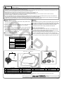
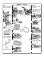
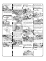
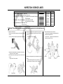
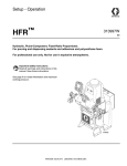
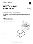
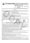
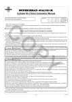
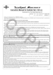
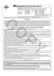
146cc strokers crank kit. Installation manual.
Super Head +R,
For only 146cc SCUT cylinder
・Thank you for purchasing one of our products. Please strictly follow the following
instructions in installing and using the kit.
・Before installing the kit, please be sure to check the kit contents. Should you have
any questions about the kit, please contact your local motorcycle dealer.
CO
◎ Please note: Illustrations and photos may vary from actual hardware.
48.5mm Stroke
Item No. :01−10−0117 (For SCUT only.)
Compatible Models and Frame Nos:
:HC07-1000001∼
Ape100
XR100 Motard :HD13-1000001∼
:HE03-2100001∼
XR100R
:HE03-2400001∼
CRF100F
Read all instructions first before starting the installation
◎ We do not take any responsibility for any accident or damage whatsoever arising from the use of the kit not in conformity with the instructions in the manual.
◎Please note that this kit is designed for exclusive use in the above-mentioned compatible models and frame numbers only and that it cannot be mounted
on other models. ◎ Installation of this kit requires removal and mounting of an engine and crankcase disassembly. We strongly recommend you to work strictly following a
HONDA genuine parts service manual for your vehicle with enough care. Besides, this instruction manual, as well as the HONDA service manual, is prepared for those who have acquired basic technical skill and knowledge. Therefore, we recommend those who are technically inexperienced or without right tools to ask a technically-trustworthy specialist shop to do the work.
◎ We shall be held free from any responsibility or compensation whatsoever for any glitch in the parts other than ours if the glitch takes place after the installation and use of the kit.
◎ If you make modifications to any product of the kit, we shall be held free from any guarantee of the product.
◎ You are kindly requested not to contact us about the combination of our products with other manufacturers'.
◎ Always use new bolts, nuts, dowel pins and packings. Never reuse severely worn-out or damaged ones.
◎ Do not use liquid packings, which may oppilate oil's passage; it may break the engine in the worst case.
◎ Be sure to always use premium unleaded petrol. And make sure to check what kind of gasoline is remaining in the fuel tank. Whenever regular gasoline
remains in the fuel tank, always replace it with high-octane gasoline.
◎ Never use on contact breaker point ignition.
◎ Applicable ignition system for stock Honda CDI or our CDI system. Never use with other manufactures ignition system.
◎ With this kit installation, a stock crankshaft will be removed, which means a loss of a centrifugal filter. So, please install an external oil filter.
◎ Install an oil cooler when necessary.
◎ Engine oil must be API SF or of a higher class, such as SAE 10W-40 / 15W-50, which are our recommendations.
◎The upper limit of revolutions varies depending on the installed cylinder head and camshaft. Please install a revolution counter to make sure that you drive
the engine at revolutions below the upper limit.
◎ Change the sprocket with the one which meets the output and specifications.
◎ This kit cannot perform on its own.
◎ This kit is only compatible with those engine parts recommended by us. So, please replace the engine parts not recommended by us with those of our
recommendations.
◎ Installation of this product requires a left side crankcase cover gasket (HONDA's item No. 11394-KN4-750), which please purchase additionally.
◎ Since this kit is designed and developed for driving in closed races, do not use the kit for running on the public road.
PY
∼ Features ∼
○The combined use of this kit with the our Cylinder head kit / Cypender kit will have a remarkable effect, increasing the engine displacement to 146 cc from
100 cc.
○Crank shaft is made light in weight with the introduction of the balance cut aimed at achieving less vibration. We have applied welding to the crank pin in
addition to usual press-fit assembly in order to reduce vibrations.
Jump-Starting and Sudden Acceleration
Please note that idling, sudden acceleration, and sudden engine braking will put a heavy load on the engine. It may result in crank shaft damage and
engine breakage in the worst case.
◎ Please be informed that, mainly because of improvement in performance, design changes, and cost increase, the product specifications and prices
are subject to change without prior notice.
◎ This manual should be retained for future reference.
The following show the envisioned possibility of injuries to human bodies and property damage as a result of disregarding the
following cautions.
・Since this kit is designed for driving in closed races, do not use the kit for running on the public road.
・Work only when the engine and the muffler are cool. Otherwise, you will burn yourself.
・Do the installation with right tools. (Otherwise, breakage of parts or injuries to yourself may take place.)
・Always use a torque wrench to screw bolts and nuts tight and securely to the specified torque.
(Otherwise, these parts may get damaged or fall off, resulting in accidents.) ・As some products and frames have sharp edges or protruding portions, please work with your hands protected.
(Otherwise, you will suffer injuries.)
・Before riding, always check every section for slack in parts like screws. If you find slack ones, screw them securely up to the specified torque.
(Or improper torque may cause parts to come off, leading to accidents.)
・Always use new gaskets, and packings. And check those parts to be reused for wear and damage. If you find worn or damaged parts, replace them with new ones.
CAUTION
-A1-
Mar./24/’
11
The following show the envisioned possibility of human death or serious injuries to human bodies as a result of disregarding the
WARNING following cautions.
・Always start the engine in a well-ventilated place, and do not turn on the engine in an airtight place.
(Otherwise, you will suffer from carbon monoxide poisoning.)
・When you notice something abnormal with your motorcycle while riding, immediately stop riding and park your motorcyle in a safe place to check what has gone wrong. (Otherwise, the abnormality could lead to accidents.) ・Before doing work, make sure your motorcycle is secure on level ground for safety's sake.
(Otherwise, your motorcycle could overturn and injure you while you are working.)
・Check or carry out maintenance of your motorcycle correctly according to the procedures in the instruction manual or service manual.
(Improper checking or maintenance could lead to accidents.) ・If you find damaged parts when checking and performing maintenance of your motorcycle, do not use these parts any longer, and replace them with new ones. (The continued use of these damaged parts as they are could lead to accidents.)
・As gasoline is highly flammable, never place it close to fire. Make sure that nothing flammable is near the gasoline. Since vaporized accumulation of
gasoline is at high risk of explosion, work in a well-ventilated place. (Otherwise, it may cause a fire.) CO
●Cautions Before Running:
● Others
① On fuel
Whenever regular gasoline is left in the fuel tank, always replace it with high-octane gasoline.
①Oil Cooler
◇ The installation of this kit increases the heat release value of the engine,
set off by the increase in power. For a long-time, high-load running, we recommend you to install an oil cooler kit which keeps the oil at appropriate
temperatures and prevents such troubles as lack of oil film at high
temperatures. But this doesn’t apply to XR100R and CRF100F.
②To use this crank kit , Centrifugal Oil Filter Rotor are not used, please equip
other type of oil filter such as our special clutch cover with filter.
③ Change of sprocket
◇ The installation of this kit increases the power. So the continued use of a
stock sprocket will result in severe wears of parts because of too low gear, not only adversely affecting the engine life, but also possibily
breaking the engine in the worst case. Therefore, please change the sprocket with the high-geared sprocket.
●Recommended engine parts
Recommended Parts
R-Stage Bore Up Kit, ST-1
R-Stage Bore Up Kit, ST-2
Super Head Bore Up Kit, +R
S-Stage Bore Up Kit
Cam Chain
Die-Hard α Cam Chain, 90L
Clutch
Dry-Type Clutch
Heavy-Duty 5-Disk Clutch Kit
Ignition System SS Outer Rotor Kit
Hyper C.D.I.
C.D.I. Magnet Kit
Oil Pump
Super Oil Pump Kit
◇The upper limt of revolutions varies depending on the installed cylinder head and camshaft. Please install a revolution counter to make sure that you drive the engine at revolutions below the upper limit.
◇Take note that idling and sudden acceleration particularly in the 1st or 2nd
gear tend to exceed the upper limit of revultions. Over revolutions will result in nonsmooth revolutions of the engine, not only adversely affecting
the engine life, but also possibily breaking the engine in the worst case.
PY
※This kit is only compatible with those engine parts recommended by us. So, please replace the engine parts not recommended by us with those of
our recommendations.
Bore Up Kit
●Upper Limt of Revolutions
∼ Kit Contents ∼
00―01―0036
1
4
Crankshaft for Repairing
3
2
A
No.
1
2
3
4
Part Name
Crankshaft COMP.
Woodruff Key
Crankcase Gasket
Right Crankcase Cover Gasket
Qty
1
1
1
1
Repair Part Item No.
00-01-0265
00-01-0011
11191-KN4-T00
11393-GCR-T01
No.
Part Name
A Radial Ball Bearings
B Timing Sprocket
B
Qty
Repair Part Item No.
2 00-01-0110
1 00-01-0266
Qty
1
1
※ Please order repair parts with the Repair Part Item No. Without the repair part item No., we may not be able to provide the correct parts.
Some parts are only available as a set. Please order them with the set number.
Co.,Ltd.
3-5-16 Nishikiorihigashi Tondabayashi Osaka Japan
-A2-
TEL : 81-721-25-1357 FAX : 81-721-24-5059 URL : http://www.takegawa.co.jp
Mar./24/’
11
∼ Installation Procedures ∼
Removal
○ Referring to the service manual,
demount an engine from the body.
○ Detach a kick-starter spring and ○ Slide the camchain away from spring collar.
sprocket to detach the crankshaft.
○ Uncover the generator.
○ Referring to the service manual,
detach a cylinder head, cylinder,
and piston.
CO
Installation:
○Apply engine oil to the bearings in
the crankcase.
○ Reinstall those parts detached at
the time of crankcase boring.
○ Install the transmission referring
to the service manual or to the
installation procedures for the transmission.
☆ In case crankcase boring is
necessary, remove a transmission
and other parts.
○Apply engine oil to the bearings in
the supplied crankshaft.
PY
○ Unfasten a flange bolt holding a crankcase.
○ Referring to the service manual,
detach a clutch cover.
Bolt
○Attach the crankshaft to the case,
passing the crankshaft through a
camchain.
○ Remove a flywheel with a special
tool.
○ Attach two stock dowel pins to
the crankcase.
○ Referring to the service manual,
detach a clutch, shift drum
stopper, shift-drum-stopper plate,
primary drive gear and oil pump.
○ Tap the crankcase, with a plastic hammer, to separate it.
Right crankcase
○ Degrease well the mating
surfaces of the crankcase, attach
the provided new crankcase
gasket, and apply engine oil to the
moving parts in the case.
Left crankcase
∴ When detaching a primary drive
gear nut, be careful not to lose an
oil-through pin.
-B1-
Mar./24/’
11
○ Set the position of the right ○Install a shift-drum-stopper plate and
crankcase and install it.
shift-drum stopper, which please tighten to the specified torque.
Caution: Apply the specified torque.
Torque: 12 N・m (1.2 kgf・m)
CO
○Install an oil pump.
Caution: Apply the specified torque.
Torque: 10 N・m (1.0 kgf・m)
○Lightly apply “Aluminum Special”,
a heat-resistant lubricating agent,
to the threaded portions of two flange bolts, which please attach
and tighten to the specified torque.
○ Install a screen.
Stopper arm
○ Install a stator coil.
○ Attach a collar and kick-starter return spring.
Bolt
Spring
Lock washer
Kick-starter return spring
Oil through pin
Spring collar
○Put a pin into the shift drum.
∴ Please clean the screen before
installing it. In the worst case, the engine may burn out if the oil cannot
pass through the screen because
of the accumulated dirt or dust on the screen.
○ Degrease well the mating surfaces
of the clutch case, and attach two
dowel pins to the case.
PY
○ Attach to the crankshaft the collar,
primary drive gear, lock washer and
oil through pin.
slightly apply grease to the lip of
the oil seal on the stator base.
And apply oil to the O-ring, and attach it to the crankcase.
Caution: Apply the specified torque.
Torque: 10 N・m
(1.0 kgf・ m)
Bolt for drum-stopper plate
Caution: Apply the specified torque.
Torque: 10 N・m
(1.0 kgf・ m)
○ If a stator base is removed, Primary drive gear
○ Apply engine oil to the threaded portion and seating face of the
primary drive gear nut, which please
install and tighten to the specified torque.
○Wire up a neutral lamp.
○ Degrease well the tapered
surfaces of the crankshaft and
flywheel. And attach the supplied
woodruff key to the crankshaft,
and then a flywheel. Tighten the
flywheel nut to the specified torque.
Caution: Apply the specified torque.
Torque: 64 N・m
○ Attach a supplied right crankcase
gasket and then an oil through.
(6.5 kgf・ m)
Caution: Apply the specified torque.
Torque: 39 N・m (4.0 kgf・m)
○ Install a gear-shift spindle.
∴ It is advisable to use a con’rod
stopper or gear holder.
○ Referring to the service manual or
to the installation procedures for the
clutch kit, install a clutch.
○Slightly apply grease to the lip of an
oil seal of the clutch cover, and then
attach a clutch case cover. Apply the aforesaid “Aluminum Special” a
little to the threaded portion of the bolt on the outside of the case.
And tighten them to the specified ○ Cut with a cutter the mating
surfaces of the cylinder to be flat.
※ Be careful not to let any gasket
chips get into the crankcase.
torque.
Caution: Apply the specified torque.
Torque: 10 N・m (1.0 kgf・m)
-B2-
○ Referring to the installation
procedures for the cylinder, install
the cylinder.
Mar./24/’
11
CO
INSPECTION / SERVICE LIMITS
Items
Internal diameter of con'rod at small end
Clearance between con'rod's small end and a pin
Misalignment on con'rod's big end (longitudinal and transversal direction)
Side clearance
Free play on the journal bearings (in the direction of shaft)
(in the direction of bearings)
Crank shaft deflection : on the right side
: on the left side
Stock
0.012∼0.036 mm
PY
Service limit
14.05 mm
0.09 mm
0.01 mm
0.5 mm
0.1 mm
0.05 mm
0.085 mm
0.070 mm
Notes
Replace
Replace
Replace
Replace
Replace
Replace
Replace
Replace
Warning: The unskilled or those without proper knowledge are requested not to do the installation work.
○ Inspection of Crank Shaft
・Check the crank shaft for damages on the flywheel-mounting
surface.
If there is a damage, replace the flywheel and the crank shaft.
・Measure the misalignment at two points at the big end of the con’rod at right angles to the shaft as shown in the figure on the right.
∴ If larger than 0.01 mm, replace it.
・Measure the deflection of the crank shaft.
∴ On the right side : Replace the crankshaft when the
deflection exceeds 0.085 mm.
On the left side : Replace the crankshaft when the
deflection exceeds 0.070 mm.
Y
X
Tapered surface
・Measure the internal diameter at the small end of the con’rod.
∴ If larger than 14.05 mm, replace it.
・Measure the clearance at the big end of the con’rod in the axial
direction.
∴ If larger than 0.5 mm, replace it.
・Measure the misalignment on the journal bearing of the crank shaft.
∴ Shaft direction:If larger than 0.10 mm, replace it.
Bearing direction: If larger than 0.05 mm, replace it.
Left side
Right side
30mm
52mm
Cylinder edge
-1-
Mar./24/’
11