1
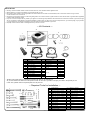
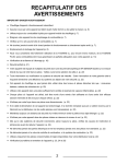
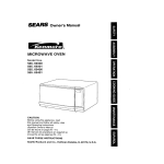
Instruction Manual for
S-Stage Bore Up Kit (115cc)
CO
Item No.:01−05−508
Applicable Models & Frame Nos
Ape100 : HC07 - 1000001∼
: HC13 - 1000001∼
XR100R : HE03 - 1200001∼
Thank you for purchasing one of our TAKEGAWA’s products. Please strictly follow the following instructions in installing and using the products. Before
fitting the products, please be sure to check the contents of the kit. Should you have any questions about the products, please kindly contact your dealer.
◎ Please note that, in some cases, the illustrations and photos may vary from the actual hardware.
! Caution about fuel to use!
This product is so designed to achieve a higher compression ratio than stock engines. As for the fuel, high-octane gasoline should always be used. In
case regular gasoline is used, abnormal combusiton takes place, and the engine cannot achieve its original performance. Moreover, it is highly likely that
the piston will break down, leading to serious failure of the vehicle. Before installing, make sure that no regular gasoline remains in the fuel tank. In case
regular gasoline is remaining in the fuel tank, do replace it with high-octane gasoline.
!Caution about spark plug!
Be sure to replace a spark plug with high thermal value of CR8HSA (NGK) or U24FSR-U(DENSO). Subsequently, choose and use a right spark plug with
the right level, depending on the degree of burning of the spark plug electrode section.
PY
Please read the following instructions before installation.
◎The following show the envisioned possibility of injuries to human bodies, and physical loss or damage as a result of disregarding the following cautions.
◎ We shall be held free from any kind of warranty whatsoever of products other than this product if the glitch takes place on the other products than
this one after the installation and use of this product.
◎ If you make alterations to the products, we shall be held free from any guarantee of them.
◎ You are kindly requested not to contact us about the combination of our products with other manufacturers'.
◎This kit is designed for exclusive use in the above-mentioned types of motorcycles and frame numbers only. Please take note that this product cannot be
mounted on other types of motorcycles.
◎Installation of this kit requires engine removal and mounting. We strongly recommend you to work strictly following HONDA genuine parts service manual
for your vehicle.
◎ For installation, please prepare tools (as specified on page 2 ) and work with reference to the installation procedures with enough care. Besides, this instruction manual, as well as HONDA’s genuine parts service manual, is prepared for persons who have acquired basic skills and knowledge in tuning.
We recommend those who are technically inexperienced or without enough tools to ask a technically-reliable specialist shop for the installation work.
◎ These products alone do not give you the maxim performance when installed on the Ape. Please separately purchase a Carburetor Kit.
Ape100 : If the carburetor on this type of motorcycle with a frame No. of HC07-1600001 ∼ or HC13-1000001 ∼ is changed, the feed pipe stay for the exhaust muffler will interfere with the carburetor. Therefore, you are required to change the muffler to a full exhaust muffler.
◎ We recommend you to install our TAKEGAWA’ muffler to make your APE more powerful.
◎ Some of bolts, nuts, dowel pins and packing will be reused. However, be sure to replace worn-down or severely-damaged ones with new ones.
◎ Never use liquid packing. It may plug the oil passage, and in the worst case break the engine.
◎ Installation of this product requires left side crank case cover gaskets (HONDA’s item No. 11394-KN4-750), which please purchase.
The following show the envisioned possibility of injuries to human bodies and property loss as a result of disregarding the following
cautions.
・Work only when the engine and the muffler are cool. (Otherwise, you will burn yourself.)
・Prepare right tools for the work, and do the work in the proper and right way.
(Otherwise, improper work could cause breakage of parts or injuries to yourself.)
・Always use a torque wrench to screw bolts and nuts tight and securely to the specified torque.
(Improper torque could cause these parts to get damaged or fall off.)
・As some products and frames have sharp-pointed or protruding portions, please work with your hands protected.
(Otherwise, you will suffer injuries.)
・Before riding, always check every section for slack in parts like screws. If you find slack ones, screw them securely up to the specified torque. (Or improper torque may cause parts to come off.)
・Check carefully gaskets and packings, and in case wear or damage is detected, always replace them with new ones.
CAUTION
The following show the envisioned possibility of human death or serious injuries to human bodies as a result of disregarding the
WARNINGS following cautions.
・Please always try to ride a motorcycle at legal speed on the public road, abiding by the law.
・Always drive the engine in a well-ventilated place, and do not switch the engine on in an airtight place.
(Otherwise, you will suffer from carbon monoxide poisoning. )
・When you notice something abnormal with your motorcycle while riding down a road, stop riding immediately and park your motorcyle in a safe place.
(Otherwise, the abnormaility could lead to an accident.)
・Before doing work, place the motorcycle on level ground to stablize the position of your motorcycle for safety's sake.
(Otherwise, your motorcycle could fall down and injure you while you are working.)
・Check or perform maintenance of parts correctly according to the procedures in the instruction manual or a service manual.
(Improper checking or maintence could lead to an accident.)
・If you find damaged parts when checking and performing maintenance, do not use these parts any longer, and replace them with new ones.
(The continued use of these damaged parts as they are could lead to an accident.)
◎ Please be informed that, mainly because of improvement in performance, design changes, and cost increase, the product specifications and prices
are subject to change without prior notice.
◎ This manual should be retained for future reference.
-1-
Dec./19/’
08
About Screws
◇ Usually, counterclockwise rotation loosens the bolts and nuts, and clockwise rotation tightens them.
◇ When tightening a screw, at first tighten it by hand at tight as you can.
◇ To loosen a screw means turning a tightened screw around three or four times counterclockwise, and to unscrew it means turning it around counterclockwise until it comes off.
◇ To tighten a screw means to keep a screw from getting loose. The numeric valve as a guide at which a screw will not break or get loose when tightened
is the so-called “tightening torque.
◇ If you do not have a torque wrench, please try to tighten a screw as tight as possible to the level where the screw will not break or get loose, though
we can not take any responsibility for the screw breakage or getting loose. In case you do not use a torque wrench, you need to judge, only by intuition
or using experience, the degree of tightening power at which the screw will break or get loose.
◇ Improper use of tools will result in breakage of the top of a bolt or screw.
CO
∼ Kit Contents ∼
2
3
1
11
12
6
7
No.
Parts Name
1
Piston 57mm
2
Cylinder COMP. 57mm
3
Piston ring set 57mm
4
Piston pin 14mm
5
Piston pin circlip 14mm
6
Cam shaft X20E68
7
Cylinder head gasket
8
Cylinder gasket
9
Exhaust pipe gasket
10
Inlet pipe gasket
11
Sealing washer
12
Oil plug bolt
4
5
PY
9
8
Qty
Repair parts item No.
10
In packs of
1
13109-GPH-T10
1
12100-KN4-T00-C
1
1
13011-GEY-T00
1SET
1
13111-KN4-T01
1
2
00-01-0052
6
1
01-08-042
1
1
1
1
1
1
1
01-13-022
1
1
1
2
2
2
90145-GEY-T00
1
∴ Please order repair parts by indicating the Repair Part Item No. as listed above.
As you see from the list, there are some parts for which we are not in a position to accept your order in the quantity of one.
In this case, please order the required parts as a set part unit.
∼ Required Tools for Installation ∼
1
9
14
2
3
10
111213
4
5
6
7
16
15
17
18
19
20
21
8
22
23
-2-
1
Torque wrench
16
Extension (medium)
2
Open-end wrench 10-12mm
17
Cross tip screwdriver (small)
3
Open-end wrench 12-14mm
18
Flat tip screwdriver (small)
4
Open-end wrench 14-17mm
19
Fine-shaft flat tip screwdriver
5
Offset box wrench 8- 9mm
20
Needle-nose plier
6
Offset box wrench 10-12mm
21
Plastic hammer
7
Offset box wrench 12-14mm
22
Thickness gauge
8
Offset box wrench 14-17mm
23
Cutter or scraper
9
Ratchet handle
Wire
10
Deep socket 8mm
Waste cloth or rag
11
Socket 10mm
Engine oil
12
Socket 12mm
Maintainance stand
13
Socket 17mm
Jack
14
Spark plug socket 16mm
Bar file
15
Extension (small)
Dec./19/’
08
∼ Installation Procedures ∼
◇Shut off the fuel petcock.
③ Exhaust Muffler Removal
Side Cover Removal
◇Unscrew a bolt on the right side cover.
The cover can be removed by detaching two bosses
from the frame.
Right side cover
●Engine Removal
① Seat and Tank Removal
XR100R
※Remove the engine from the frame following the
instructions on the owner’s / service manual.
◇Unscrew two bolts, and remove the seat by
pulling it toward the back of the vehicle.
Tool: Offset box wrench 10-12mm
Seat
Hook
◇Disconnect the wiring of the breather hose.
(in the case of Ape)
Ape
◇Loosen the nut on a clutch cable guide, and
disconnect a clutch cable from a lifter lever.
Tools: Open-end wrench 10-12mm
Open-end wrench 12-14mm
Bosses
CO
◇Stabilize the body firmly with a racing stand or the
like in order to remove the side stand.
※Work only when the engine and the muffler are cool.
※Take off all dirt like the dust and oil on each part as
you detach it.
※Don’t let the removed bolts and nuts go astray, and keep them orderly so you can recall where to
fix them.
◇Shift the tube clip to disconnect the fuel tube.
◇Take off two nuts on the cylinder head side.
Tool: Open-end wrench 10-12mm
Bolt
◇Dismount three bosses on the left side cover from
the frame, then the side cover becomes detached.
◇Unscrew and remove mounting bolts and
washers, and detach an exhaust muffler.
Tool: Offset box wrench 10-12mm
Bosses
Left side cover
PY
② Carburetor Removal
④ Spark Plug Removal
◇Remove a carburetor’s top cap, and pull out the throttle valve from the carburetor.
◇Pull a plug cap to demount it. Be sure to pull the
cap, not a wire.
◇Disconnect the clutch cable from the cable guide.
◇Remove a spark plug.
Tools: 16mm spark plug wrench,
Ratchet handle
◇Loosen a screw on the connecting tube band.
Tool: Cross slot screwdriver (small)
⑥ Drive Sprocket Removal
◇Unscrew five bolts on the left side crankcase cover, and remove the left side crankcase cover.
Tools: Deep socket 8mm
Ratchet handle
⑤ Wiring Disconnection
◇Disconnect the wiring.
◇Unscrew two bolts, and remove a manifold and the
carburetor from the cylinder head.
Tool: Offset box wrench 8-9mm
Bolts
◇Unscrew a bolt and remove the fuel tank by pulling
it toward the back of the vehicle.
Tool: Offset box wrench 10-12mm
Fuel tank Bolt
Wire band
◇Remove a wire band.
◇If the gasket material remains on the mating
surfaces, get rid of it with a cutter or a scraper.
◇Remove a spacer in advance.
Collar
Spacer
-3-
Dec./19/’
08
◇Unscrew two bolts on the drive sprocket, and
◇Detach four nuts on a front engine hanger, take
◇Take out the bolt on the lowr side, and detach the
remove a fixing plate and the drive sprocket.
Tools: 10mm socket,
four bolts out, and remove the front engine hanger.
Tools: 10-12mm closed wrench,
engine from the left side of the frame. Be careful not to give scratches to the frame.
Extension bar (small), and
Ratchet handle.
12mm socket, and
Ratchet handle.
CO
◇Detach the cam sprocket from the cam shaft and
then, from the cam chain.
●Removal of Cylinder Head,
Cylinder, and Piston
◇Remove a nut on the upper rear engine mount.
Tools: Offset box wrench 10-12mm
12mm socket,
Extension bar (medium)
① Cylinder Head Removal
Ratchet handle
⑦ Left Step Removal
◇Remove the side stand switch cord from the frame.
◇Remove a bottom side nut also.
Tools: Offset box wrench 10-12mm
12mm socket,
Extension bar (small)
Ratchet handle
◇Unscrew two bolts, and remove the left step.
Tool: Offset box wrench 14-17mm
◇Remove two hex’ bolts from the cam sprocket.
◇Unscrew two bolts on the cylinder head cover, and
remove the cylinder head cover and its gasket.
Tool: Offset box wrench 10-12mm
◇Suspend the cam chain with a wire or the like to
keep it from falling into the case.
PY
◇Demount a cylinder head mounting bolt.
Tool: Offset box wrench 10-12mm
◇Fix a flywheel, and loosen two hex’ bolts on a cam
sprocket.
Tools: Offset box wrench 10-12mm
17mm socket, and
Ratchet handle.
◇First, pull out the upper side bolt and then remove
a collar (Ape) and the clutch cable guide.
◇Loosen four cam shaft holder nuts in several steps
diagonally, and remove four washers, a cam shaft
holder, a cam shaft, and dowel pins.
Tool: Offset box wrench 10-12mm
◇Unfasten a lock bolt and a set plate, and remove an
adjuster.
⑧ Engine Removal
Tools: Offset box wrench 10-12mm
Needle-nose plier,
◇Place a jack or substitute stand under the engine
to hold up the engine.
Set plate
Lock bolt
-4-
Dec./19/’
08
② Cylinder Removal
④ Mating Surface Cleaning
◇Remove the cam chain guide, and pull out the
◇Detach a spring, and remove a cam chain ◇Completely get rid of the gasket scraps on the cylinder. (If it is hard to pull it out, hit the cylinder
lightly with a plastic hammer.)
tensioner from the cylinder.
mating surface with a cutter or a scraper.
Be careful not to give scratches to the surface.
CO
Cam chain guide
◇Remove the cylinder head.
◇Detach two dowel pins in advance and keep them
for re-use.
◇Wipe the surface with a waste cloth.
◇Plug the cylinder hole on the crankcase and a cam chain hole with a waste cloth or clean rag not
to let any dirt or part fall into the hose.
◇Take off two dowel pins in advance and keep them
for reuse.
PY
◇Remove a lock nut and an adjust bolt from the cylinder.
Tools: Offset wrench 10-12mm
Flat tip screwdriver (small)
● Crankcase Modification
※In fixing the cylinder onto the crankcase, there are
some cases where a cylinder sleeve and a
crankcase sleeve hole may interfere with each other,
due to right and left crankcases being out of
alignment and for other reasons. Since the use of
such a crankcase with two parts interfering each
other will lead to sleeve deformation and engine troubles, do not fail to check the crankcase for the
interference.
③ Piston Removal
◇Remove one of the two piston pin circlips.
You can remove it by prising it open with a
screwdriver with its tip on the notch.
Tool: Fine-shaft flat tip screwdriver, or
needle nose plier
Piston pin circlip
◇With a cutter or a scraper, get rid of the gasket scraps remaining on the cylinder head plane on which to fit a manifold.
Piston
Cylinder sleeve
Interference part
◇Plug the hole in the crankcase with a waste cloth
not to let cutting chips get into the case.
◇Scrape the convex parts on both right and left
crankcases till the mating surfaces become level.
◇After scraping, remove the cloth with enough care
not to let any chip get into the case.
Left side
crankcase
Right side
crankcase
◇Push out the piston pin with a driver or the like in
the direction where one of the two circlips has just
been removed.
After scraping
◇Stuff up the sleeve hole with some clean cloths.
◇After installation of the kit, idle away the engine for
a few minutes, and replace the engine oil with the
new one without delay.
◇Now you can take out the piston.
-5-
Dec./19/’
08
●S-Stage Kit Installation
① Piston Installation
◇Fix the second ring, turning up the side with an
◇Fix the other piston pin circlip, included in the kit,
◇Degrease the mating surfaces of the crankcase
engraved letter “N”.
to the pin hole.
and the cylinder with thinner or the like.
◇Fix one of kit’s piston pin circlips to a pin hole.
※Place the circlip in a position so the end-gaps of
a piston pin circlip do not meet with the notch on
※Place a circlip so its end gap does not meet with
the notch on the pin hole.
the hole.
※It is relatively easier to press it by a driver with ※You can rather easily install it by pressing it into
care not to give scratches to the piston.
the piston with a screwdriver, but taking care not
to damage the piston with a screwdriver.
※Do the job carefully as, in some cases, the piston
pin circlip may come off flying while you press it ※Do the job carefully as, in some cases, the circlip
comes off flying while you press it inside.
inside.
Tools:Fine-shaft flat tip screwdriver, or
Tools:Fine-shaft flat tip screwdriver, or
needle nose plier
CO
needle nose plier
◇Fix the top ring, turning up the side with an
engraved letter “N”.
◇Fix piston rings according to the figure below.
Piston ring colors
Top ring : Gold
Top
ring
ト
ップリング
120°
120°
120°
Second
ring
セカンドリ
ング
エキスパンダー
Expander
サイ
ドレ
ール
Side
rails
◇Attach two dowel pins and a cylinder gasket to
◇Insert the cam chain tensionner into kit’s
the crankcase.
cylinder, and hang the hook of the spring on the
cylinder.
◇Apply engine oil to the piston pin hole.
2nd ring : Black
② Cylinder Installation
PY
◇Apply engine oil to the inside of the cylinder and
spread it with fingers to be equally applied all over.
60°
60°
◇Apply engine oil to a piston pin hole in the con’rod.
◇Fix the oil ring expander.
◇Place the cam chain tensioner in a position so the
end of the rod will be nearly on the same level as
◇Apply engine oil to the piston pin and place the piston in a position so the “EX” mark on the upper
the clamp face.
Fix it with an adjust bolt and tighten the lock nut.
◇Apply engine oil to whole surface of the piston,
side of the piston faces the front or exhaust side.
Tools:Flat tip screwdriver (small)
and the piston rings.
Offset box wrench 10-12mm
Rod’s
end
◇Fix the lower oil ring side rail.
◇Let the cylinder in.
◇Fix the upper oil ring side rail.
EX
◇Remove the waste cloth.
-6-
Dec./19/’
08
◇Insert the piston into the cylinder gradually by hand
with care not to shift the piston ring’s end gaps out
of the position.
◇Pass the cam chain through the cylinder head ◇In case of there is no interference, continue the
◆Fit the camshaft into the camshaft holder to see if
and install the cylinder head to the cylinder.
installation work.
there is no interference with a cam top and rocker
※If there is interference, modify the camshaft holder
and rocker arm by rasping the interfering
arm.
portions. Do the following work marked with ◆.
◆Pull out the rocker arm shaft from the camshaft CO
holder in order to remove the rocker arm.
◇Install an adjuster, passing it through the cam ◇When the piston is completely in the cylinder, pass
the cam chain through the cylinder and install the
cylinder to the crankcase.
chain tensioner and the cylinder head.
◇Apply engine oil to the journals and cams of a kit’s
cam shaft. And install the cam shaft to the cylinder
head with the cam’s top faces downward.
Cam
◆Modify the rocker arm by rasping its interfering
portions.
Tools to use:
For modifying the camshaft holder:
◇Temporarily attach a set plate with a lock bolt.
Bar rasp
Hand grinder or electric hand grinder
For modifying the rocker arm:
◇Insert the cylinder, fitting the end of a cam chain
guide into grooves in the crankcase and the
protrusion into grooves in the cylinder.
Protrusion
Top end
Cam
chain
カムチェ
ーンガイド
シリンダー
Cylinder
クランクケース
Crankcase
PY
rocker arm and the cylinder head.
WARNING : In case you use a hand grinder, do
the work, protecting your eyes to
prevent chips from getting into your
eyes.
◇Check the camshaft holder and rocker arm for the
◇Degrease the mating surfaces of the cylinder and
the cylinder head with thinner or the like.
Dowel pins
scratches to the cam shaft holder’s
journal, and clamp faces for the ④Installation of Cam Shaft and
Cam Sprocket
③ Cylinder Head Installation
Journal
◇Attach two dowel pins.
CAUTION : Do not shave off more than needed.
CAUTION : Work with great care not to give ◇Temporarily tighten the cylinder head mountiong
bolts.
guide
Hand grinder or electric hand grinder
Diamond file
◇Install the cam shaft holder.
◇Fix four washers.
interference with the camshaft.
(The supplied camshaft is designed to have higher
lift than a stock camshaft. Some of the camshaft holders and rocker arms may interfere with the camshaft because of the size difference of these
parts. So, never fail to check them for the
interference.)
◇Fit the provided camshaft into the camshaft holder
to see whether the camshaft top, cam shaft holder
◇After shaving, check for any burr, and clean up the
cam shaftholder.
and rocker arm do not interfere with one another.
◆Apply molybdenum solution to the rocker arm shaft.
◇Install and diagonally tighten four nuts equally in
Install the rocker arm onto the camshaft holder.
a few steps.
Tools:12mm socket, and
MO-OIL
torque wrench
Torque: 20N・m (2.0 kgf・m)
◇Attach two dowel pins and a cylinder head gasket
to the cylinder.
Dowel pins
Cylinder head gasket
-7-
Dec./19/’
08
●Engine Mounting
⑤ Cam Chain Adjustment
◇Fully tighten the cylinder head mounting bolts.
Tools:10mm socket,
※A camchain, whether tightly or loosely streteched,
will impair the engine conditions. Perform this
◇Fix the adjust bolt with a flat tip screwdriver, and
tighten the lock nut.
extension bar (small), and
torque wrench
procedure correctly.
◇Rotate the flywheel till both cam tops of the cam Tools: Flat tip screwdriver (small),
Torque: 12 N・m (1.2 kgf・m)
shaft point up.
12mm socket, and
Torque wrench
Specified torque: 12 N・m (1.2 kgf・m)
Cam tops should point this way.
CO
◇Again, move the adjuster and hold it where the camchain has no slackness and you do not feel it
※Mount the engine on the frame following the
instructions of the owner’s / service manual.
◇Place a jack or a proper stand under the engine
to support the engine. Then mount the engine from
the left side of the vehicle.
◇Insert a bolt into the lower part of the rear engine
mount from the left side.
⑥ Valve Clearance Adjustment
◇Rotate the flywheel counterclockwise, and stop
rotating it where the “O” mark on the cam sprocket
is on the top and the “T” mark on the flywheel is ◇Rotate the flywheel a little by hand. Depending on
Alignment mark
XR100R
hard to rotate the flywheel. Then tighten the lock
bolt to fix the adjuster.
◇Check that “T” mark on the flywheel is aligned with
the “▽” mark on the crankcase.
① Engine Mounting
aligned with the “▽” mark on the crankcase.
how tensely or loosely the camchain is stretched
to the camsprocket, turn the flywheel in either
◇Insert a 0.05mm thickness gauge between the adjust screw and the end face of the valve
direction to get the proper tension of the camchain,
watching the “O” mark on the adjuster.
(or, valve clearance).
Tool: Thickness gauge
Tool: Flat tip screwdriver (small)
◇Attach a collar and a clutch cable guide, and
insert a bolt into the upper part of the rear engine
mount.
“T” mark
◇Install the cam chain in the position so the “O” mark on the cam sprocket is right at the top. Fit the
cam sprocket into the cam shaft.
Adjuster
Loosen
ゆるむ
PY
標準位置
Standard
◇Adjust the position of the adjust screw so that there is a little resistance to pulling the gauge position
out. Then tighten the nut.
Tools: Thickness gauge,
張る
Tighten
◇Rotate the flywheel a little, and then rotate the cam
sprocket to mark it easy to install hex’ bolts.
◇Align cam shaft’s bolt-holes with the cam sprocket.
Then attach two hex’ bolts to the holes by hand
temporarily. At this point, attach and tighten a dowel
bolt (black) to the intake side.
セッ
トプレート
Set
plate
Lock bolt
Offset box wrench 8-9mm,
XR100 Needle nose plier, and
◇Temporarily tighten the two nuts.
Ape
Flat tip screwdriver (small)
Torque: 10 N・m (1.0 kgf・m)
◇Tighten the lock bolt fully when the cam chain is
found stretched properly and you can move the flywheel
without difficulty, and fix the adjuster.
Tools: 10mm socket, and
Torque wrench.
Torque: 10 N・m (1.0 kgf・m)
◇After tightening the nut, double check the valve
clearance with the 0.05mm thickness gauge.
◇Pour fresh engine oil to a oil pool on the cylinder
head to the brim.
“O” mark
◇Attach a front engine hanger, and insert four bolts
from the left side and temporarily tighten four nuts.
◇In case you can not get the proper tension of the
camchain only by adjusting the adjuster, then
adjust the tension with the adjust bolt on the
cylinder.
◇Fix the adjuster where it has the best tension.
Then loosen a lock nut on the cylinder, and loosen
the adjust bolt a little bit.
Black bolt
◇Fix the flywheel and fully tighten the hex’ bolts on ◇Install the cylinder head cover and its gasket to the cam sprocket.
Tools:10mm socket,
the cylinder head by tightening two cylinder head
cover bolts.
Tool: Offset box wrench 10-12mm
torque wrench, and
Offset box wrench 14-17mm
Torque: 12 N・m (1.2 kgf・m)
Torque: 12 N・m (1.2 kgf・m)
-8-
◇Fix the drive sprocket with the drive chain to the counter shaft.
If it is hard to fix the drive sprocket, fix it while
shaking the engine lightly.
Dec./19/’
08
◇Stretching the drive chain moderately loosely, fully
tighten the two nuts on the rear engine mount and
◇Fix the side stand switch cord on the clamp of the
frame.
⑤ Spark Plug Installation
● Side Cover Installation
◇At first, screw the spark plug by hand.
(In the case of the Ape)
(In the case of using a stock
air cleaner box)
◇Then tighten it with a plug wrench.
Tools: Spark plug wrench 16mm, and
the four nuts on the front engine hanger plate.
Tools: Offset box wrench 10-12mm,
Ratchet handle
12mm socket,
Torque: 14 N・m (1.4 kgf・m)
Extension bar (small),
Extension bar (mid-size), and
CO
◇Fix the left side cover by fitting three bosses on this cover into the frame.
Bosses
Ratchet handle
Torque:
for rear engine mount nuts
: 44 N・m (4.5 kgf・m)
for front engine hangar plate nut
: 26 N・m (2.7 kgf・m)
◇Fit the fixing plate into the counter shaft to align with the threaded holes on the drive sprocket, and
fix two bolts.
④ Wiring
◇Connect the wiring.
Left side cover
◇Fix a plug cap.
Tool: Offset box wrench 10-12mm
◇Fit two bosses on the right side cover into the Torque: 10 N・m (1.0 kgf・m)
frame, and fix the bolt.
◇Fix the cords with a wire band.
② Installation of Left Side
Crankcase
◇Degrease the clamp faces of the left side
crankcase cover and the crankcase with thinner or
the like.
◇Attach a spacer, and install the left crankcase cover and a new gasket to the crankcase by
tightening five bolts.
Tools: 8mm deep socket,
Ratchet handle
Torque: 12 N・m (1.2 kgf・m)
Wire band
◇Connect the breather hose.
(for Ape)
Right side cover
Bolt
PY
⑥ Exhaust Muffler Installation
XR100R
※Mount the engine on the frame following the
instructions on the owner’s / service manual.
◇Temporarily tighten two nuts on the cylinder head
⑧ Installation of Seat and Tank
(for Ape)
◇Install the fuel tank to the frame with the bolt.
Tool: Offset box wrench 10-12 mm
Torque: 26N・m (2.7 kgf・m)
Fuel tank
Bolt
Collar
side.
Tool: Open-end wrench 10-12mm
Ape
◇Temporarily tighten two mounting bolts and washers.
Spacer
Bosses
◇Fit the hook in the front on the back side of the seat
into the frame and fix it by tightening two bolts.
Tool: Offset box wrench 10-12 mm
Torque: 26N・m (2.7 kgf・m)
Hook
Seat
Tools: Offset box wrench 10-12mm, and
Offset box wrench 14-17mm
◇Attach the clutch cable to the lifter lever and install
it to the clutch cable guide. Then tighten the nut.
Tools: Offset box wrench 10-12mm
Offset box wrench 12-14mm
Bolts
●Fuel Hose Connection
◇Connect the fuel tube with the fuel petcock, and fix
③ Installation of Left Side Step
(for Ape)
◇Fully tighten them.
it with a tube clip.
Torque:
for two nuts: 12 N・m (1.2 kgf・m)
◇Install the left side step to the frame with two bolts.
for mounting bolts: 20 N・m (2.0 kgf・m)
Tool: Offset box wrench 14-17mm
Torque: 26 N・m (2.7 kgf・m)
⑦ Carburetor Installation
Ape
※This kit will not display its potential high
performance when used with a stock carburetor.
Please purchase separately a Carburetor Kit.
※For the installation, please refer to the Instruction
Manual of the Carburetor Kit.
XR100R
※Install the carburetor with reference to the owner’s
/ service manual.
-9-
Dec./19/’
08
☆Engine Starting
о After checking that the ignition key and the fuel cock are turned OFF, remove the spark plug.
о Kick the starter for a while to circulate the engine oil all aroud the engine.
о Reinstall the spark plug, turn ON the fuel cock and ignition key, and pull the choke lever to start the engine.
CO
CAUTION: Be sure to tighten to the specified torque.
WARNING: Work in a well-ventirated area.
о Check for any abnormarity such as abnormal noises.
о If no problem is detected, do running-in at leaset 100 to 150 km.
о After the initial running-in, check for abnormality such as abnormal noises or blow-bye.
(If there is a problem, disassemble the engine again to check each part.)
WARNING: Do not re-use wrist pin circlips.
Caution
оEven bolts and nuts tightened to the specified torque may get loose by repeated heat expantion through warm-up at the time of
engine assembly. Retighten bolts and nuts periodically.
CAUTION: Be sure to tighten to the specified torque.
●Cautions Before Running
① About fuel
PY
Always replace the gasoline with high-octane gasoline when regular gasoline is remaining in the fuel tank.
②Sprocket (for APE only)
Adjust the sprockets depending on how you ride your vehicle. However, setting in too low gears will result in severe wears of parts, not only adversely
affecting the engine life, but also breaking the engine in the worst case. Please drive your vehicle at proper setting.
● Other notes
①Oil Cooler (for APE only)
The installation of this Kit increases the heat release value of the engine, set off by the increase in power. Therefore, we recommend that you equip your
machine with an Oil Cooler Kit (09-07-121: Black core, 09-07-221: Silver core, 09-07-208: Solid) for long-hour, high-load driving.
② Cam Chain
We recommend you to install our TAKEGAWA’s solid cam chain, and die-hard α (01-14-005) to cope with the increase in power and in heat release value of the engine.
③ Thermometer
A stick-type temperature sensor is installable on the cylinder side of this kit.
TAKEGAWA’s meters listed below are available.
・Medium LCD tachometer & thermometer: 09-05-0141 (up to 150°)
・Digital thermometer: 07-04-053 (up to 99°)
Co.,Ltd.
3-5-16 Nishikiorihigashi Tondabayashi Osaka Japan
TEL : 81-721-25-1357 FAX : 81-721-24-5059
URL : http://www.takegawa.co.jp
-10-
Dec./19/’
08