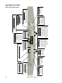
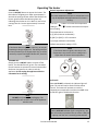
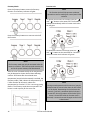
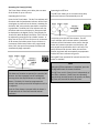
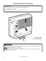
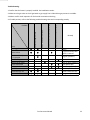
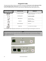
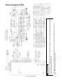
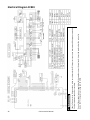
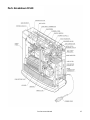
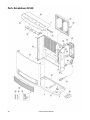
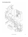
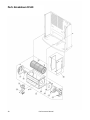
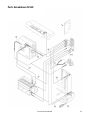
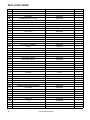
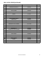
1
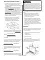
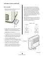
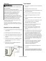
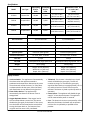
Gas Fan Convection Heater Installation and Operation Manual FC510 ................... (RCE-391A) FC824 ................... (RCE-691TA) Installer: Leave this manual with the appliance. Consumer: Retain this manual for future reference. ANS Z21.11.2 WARNING If the information in these instructions is not followed exactly, a fire or explosion may result causing property damage, personal injury or loss of life. — Do not store or use gasoline or other flammable vapors and liquids in the vicinity of this or any other appliance. — BEFORE OPERATING smell around the appliance for gas. Be sure to smell next to the floor because some gas is heavier than air and will settle on the floor. — WHAT TO DO IF YOU SMELL GAS Do not try to light any appliance. Do not touch any electrical switch; do not use any phone in your building. Immediately call your gas supplier from a neighbor’s phone. Follow the gas supplier’s instructions. If you cannot reach your gas supplier, call the fire department. — Installation and service must be performed by a qualified installer, service agency, or gas supplier. This is an unvented gas-fired heater. It uses air (oxygen) from the room in which it is installed. Provisions for adequate combustion and ventilation air must be provided. Refer to page 6 of this manual. READ ALL OF THE INSTRUCTIONS THOROUGHLY BEFORE INSTALLING OR OPERATING THIS HEATER. This manual provides information on the installation, operation, and maintenance of the heater. For proper operation and safety, it is important to follow the instructions and adhere to the safety precautions. A licensed professional must install the fan convection heater according to the exact instructions within this manual. The consumer must read the entire manual to properly operate the heater and for instructions on regular maintenance required to be performed. This appliance may be installed in an aftermarket, permanently located, manufactured (mobile) home, where not prohibited by local codes. This appliance is only for use with the type of gas indicated on the rating plate. This appliance is not field convertible for use with other gas types. Service should be performed only by a licensed professional. Table of Contents Table of Contents ..................................................... 2 Safety Definitions ..................................................... 2 Safety Behaviors and Practices for the Consumer and Installer ............................................ 3 Installation Instructions........................................ 4 Installer Qualifications ....................................... 4 General Instructions .......................................... 4 Determine Installation Location ........................ 6 Clearances ......................................................... 6 Gas Connection.................................................. 7 Electricity ........................................................... 8 Checklist for Gas and Electricity ........................ 8 Final Check List ........................................................ 8 Specifications...................................................... 9 Operation Instructions .......................................... 10 Consumer Guidelines for Safe Operation ........ 11 FC510 Control Panel Layout ............................ 13 FC824 Control Panel Layout ............................ 14 Operating the Heater Turning ON and OFF ..................................... 15 Room Temperature Adjustment .................. 15 Auto Off ........................................................ 15 Economy Mode............................................. 16 Function Lock ................................................ 16 Operating the Timer(s) ................................17,19 FC510 Timer.................................................. 17 FC824 Timer .................................................. 19 Setting the Clock (FC824 Only) ......................... 18 Program On/Off Timer(s)(FC824 Only) ............ 18 Override Function ............................................ 19 Required Maintenance..................................... 20 Troubleshooting ............................................23 Diagnostic Codes ........................................... 24 Electrical Diagram FC510 ............................... 25 Electrical Diagram FC824 ............................... 26 Parts Breakdown.............................................. 27-40 FC510 ............................................................ 27-33 FC824 ............................................................ 34-40 State Regulations ................................................... 41 Consumer Support Limited Warranty Information ................... 42-43 Privacy Notice ........................................................ 43 Important Safety Information Safety Definitions This is the safety alert symbol. This symbol alerts you to potential hazards that can kill or hurt you and others. 2 DANGER Indicates an imminently hazardous situation which, if not avoided, will result in death or serious injury. WARNING Indicates a potentially hazardous situation which, if not avoided, could result in death or serious injury. CAUTION Indicates a potentially hazardous situation which, if not avoided, could result in minor or moderate injury. It may also be used to alert against unsafe practices. Fan Convector Manual Safety Behaviors and Practices for the Consumer and Installer WARNING Before operating, smell all around the appliance area for gas. Be sure to smell next to the floor because some gas is heavier than air and will settle on the floor. Ensure the room is sufficiently ventilated. Consult your Early signs of carbon monoxide poisoning resemble the flu, with headaches, dizziness, or nausea. If you have these signs, the heater may not be working properly. Get fresh air at once! Have heater serviced. Some people are more affected by carbon monoxide than others. These include pregnant women, people with heart or lung disease or anemia, those under the influence of alcohol, and those at high altitudes. Do not use substitute materials. Use only parts certified Keep the area around the appliance clear and free from combustible materials, gasoline, and other flammable vapors and liquids. Never store liquid propane containers indoors. Combustible construction refers to adjacent walls and ceiling and should not be confused with combustible or flammable products and materials. Combustible and/or flammable products and materials should never be stored in the vicinity of this or any gas appliance. Use only your hand to push in or turn the gas control knob. Never use tools. If the knob will not push in or turn by hand, do not try to repair it; call a licensed professional. Force or attempted repair may result in a fire or explosion. local gas authority for information on ventilation requirements. with the appliance. Should overheating occur or the gas supply fail to shut off, turn off the manual gas control valve to the appliance. Do not use an extension cord or an adapter plug with this appliance. This appliance is equipped with a three-prong plug for your protection against shock hazard and should be plugged directly into a properly grounded three-prong receptacle. Do no cut or remove the ground prong from this plug. Do not operate appliance with the front panels removed, cracked, or broken.. Replacement of the panels should be done by a licensed professional. Do no move the heater while it is turned on. Any alteration to the appliance or its controls can be dangerous and will void the warranty. Do not use heater if any part has been under water. Immediately call a qualified service technician to inspect the room heater and to replace any part of the control system and any gas control which has been under water. CAUTION Do not install this appliance above 2,000ft. Do not block the warm air discharge. Do not allow anyone to sleep directly in front of the appliance. Due to high temperatures, the appliance should be located out of traffic and away from furniture and draperies. Children and adults should be alerted to the hazards of high surface temperature and should stay away to avoid burns or clothing ignition. Young children should be carefully supervised when they are in the same room as the appliance. Any safety screen or guard removed for servicing must be replaced prior to operating the appliance. Do not insert items into the louvers. Do not spray aerosols near the appliance while it is operating. Most aerosols contain butane gas which is flammable. Do not install this appliance in areas where spray painting or plating is taking place, or in places such as hair salons where there may be large amounts of dust, chemical residue, or debris. Using the appliance in such areas may result in strong odors or irritated eyes and sinuses. Turn off the appliance when not in use or when away for long periods of time. Do not sit on the appliance. Do not unplug the appliance while it is operating or while the fans are on. Do not use a plug in type timer with this appliance. Do not place clothing or other flammable material on or near the appliance Fan Convector Manual 3 Installation Instructions Installer Qualifications MUST DO A licensed professional must install the appliance, inspect it, and leak test it before use. The warranty will be voided due to improper installation. The installer should have skills such as: gas sizing connecting gas lines and electricity knowledge of applicable national, state, and local codes If you lack these skills, contact a licensed professional. Type of installation This appliance is equipped only for use with type of gas indicated on the rating plate. This appliance is not convertible for use with other gases. The installation must conform with local codes or, in the absence of local codes, with the National Fuel Gas Code, ANSI Z223.1/NFPA 54, or the Natural Gas and Propane Installation Code, CSA B149.1. If installed in a manufactured home, the installation must conform with the Manufactured Home Construction and Safety Standard, Title 24 CFR, Part 3280 and/or CAN/SCA Z240 MH Series, Mobile Homes. The appliance, when installed, must be electrically grounded in accordance with local codes or, in the absence of local codes, with the National Electrical Code, ANSI/NFPA 70. The appliance and its appliance main gas valve must be disconnected from the gas supply piping system during any pressure testing of that system at test pressures in excess of 1/2 psi (3.5 kPa) (13.84 in W.C.). You must follow the installation instructions and Installation Steps General Instructions .......................................... 4 Determine Installation Location ........................ 6 Clearances.......................................................... 6 Gas Connection .................................................. 7 Electricity ........................................................... 8 Checklist for Gas and Electricity ........................ 8 Final Checklist .................................................... 8 General Instructions those in Care and Maintenance for adequate combustion air intake and exhaust. INFORMATION Should overheating occur or the gas supply fail to shut off, turn off the manual gas control valve to the appliance. Keep the installation location free of chemicals such as cleaners that produce fumes. These fumes can damage components and reduce the life of your appliance. Do not spray aerosols near the heater while it is in DO NOT Do not obstruct the flow of combustion and ventilation air. use. Many aerosols contain butane gas and can be a fire hazard. Use of aerosols, paint, polishes, etc. while the heater is in use may also create odors as well as irritate the eyes and sinuses. Do not use substitute parts that are not authorized for this appliance. WARNING This appliance is available in natural gas or propane versions. The appliance cannot be field converted from one gas type to the other. 4 Fan Convector Manual General Instructions (continued) Prepare for installation A licensed professional should install the appliance and inspect it before use. When unpacking the appliance, check for the correct gas type and for damage. The Operation and Installation Manual and a manual gas valve are included. This appliance is intended for supplemental heating only. The International Fuel Gas Code Standard 620-6 “Prohibited Use” states that “One or more unvented room heaters shall not be used as a sole source of comfort heating in any dwelling”. Do not install this appliance in a bedroom or bathroom. Do not install this appliance in a windy area such as facing a window or near a door leading to the outside. If you move, check the gas type in your new area. The local gas authority will be able to advise on local regulations. If the flooring is carpet, tile, or other combustible material other than wood, then the appliance must be installed on a metal or wood panel extending the full width and depth of the appliance. This appliance discharges a large volume of warm air next to the floor. Any particles in the air such as cigarette smoke, lint, dust, or debris could cause discoloration in nylon carpets containing dyes or vinyl surfaces. This appliance is not designed to be built into or mounted directly in a wall Rinnai suggests that a dedicated electrical circuit with a 120VAC, 60 hz, 10 amp power source be used. A 1/8” test plug is provided for testing of manifold differential pressure. It is located on the modulating gas valve. The flow of combustion and ventilation air must not be obstructed. Note that in some regions, an unvented gas heater will increase the amount of humidity in the room. Parts included Gas Fan Convection Heater Anchors Screws Manual Gas Shut Off Valve Floor Fixing Plate Tools needed Pipe wrenches (2) Gloves Adjustable pliers Safety glasses Screwdrivers (2) Level Wire cutters Tools that might be needed Saw Threading machine with heads and oiler Steel pipe cutter Materials needed Soap solution or other appropriate leak detector solution. Approved pipe thread pipe sealant for either natural gas or propane. Fan Convector Manual 5 WARNING Determine Installation Location The heater must not be installed in a confined space or unusually tight construction unless provisions are provided for adequate combustion and ventilation air. National Fuel Gas Code, ANSI Z223.1/NFPA 54 defines a confined space as a space whose volume is less than 50 cubic feet per 1,000 BTU per hour (4.8m³ per kW) of the aggregate input rating of all appliances installed in that space and an unconfined space as a space whose volume is not less than 50 cubic feet per 1,000 BTU per hour (4.8m³ per kW) of the aggregate input rating of all appliances installed in that space. Unusually tight construction is defined as construction where: Rooms connecting directly with the space in which the appliances are installed, through openings not furnished with doors, are considered a part of the unconfined space. Walls and ceilings exposed to the outside atmosphere have a continuous water vapor retarder with a rating of 1 therm or less with openings gasketed or sealed; Weather stripping has been added on openable windows and doors; and caulking or sealants are applied to areas such as joint around window and door frames, between sole plates and floors, between wall ceiling joints, between wall panels, at penetrations for plumbing, and gas lines, and at other openings. If the area in which the heater may be operated is smaller than that defined as an unconfined space or if the building is of unusually tight construction, provide adequate combustion and ventilation air by one of the methods described in the National Fuel Gas Code, ANSI Z223.1/NFPA 54, Section 5.3 or applicable local codes. Clearances The minimum clearances from combustible materials and for proper operation and servicing are as follows: 2 inches from top 2 inches from back (measured from the base of the appliance) 2 inches from sides 30 inches from front For example: 0 inches from bottom If L1=15.5 ft, L2=12 ft, W=12 ft, H=8 ft, and there is no door between the rooms, then for the space to be considered unconfined the maximum rating is: In addition, do not install in areas where curtains, drapes, clothing, or other moving flammables are within 12 inches of the appliance. The following formula can be used to determine the maximum heat rating for a given unconfined space: BTU/HR= (L1+L2) X W X H X 1000 50 (All dimensions are in feet.) (15.5+12) X 12 X 8 X 1000 50 =52,800 BTU/HR If there is a door between the 2 rooms then for the space to be considered unconfined the maximum rating is: 15.5 X 12 X 8 X 1000 50 =29,760 BTU/HR If the appliance rating exceeds the maximum heater rating in the calculation above, the space is confined. 6 Fan Convector Manual Installation Location (continued) Gas Connection 1. Attach 2 fixing plates to the bottom of the base plate before connecting the gas. 7. After completion of gas pipe connections, all joints including the heater must be checked for gas tightness by means of leak detector solution, soap and water, or an equivalent nonflammable solution, as applicable. (Since some leak test solutions, including soap and water, may cause corrosion or stress cracking, the piping must be rinsed with water after testing, unless it has been determined that the leak test solution is noncorrosive.) 8. After completing pipework, secure the heater to the floor. Use the 2 screws provided, as shown in the drawing. To avoid deforming the floor plate, do not over torque the screws. 2. The gas supply line must be gas tight, sized and installed so as to provide a supply of a gas sufficient to meet the maximum demand of the heater without loss of pressure. 3. The supplied shut off valve must be installed in the upstream of the gas line to permit servicing. 4. Flexible pipe and any appliance connector valve used for gas piping must be types approved by nationally recognized agencies. 5. Any compound used on the threaded joint of the gas piping must be a type which resists the action of liquefied petroleum gas (propane / LPG). 6. Check the gas supply pressure immediately upstream at a location provided by the gas company. Supplied gas pressure must be within the limits shown in the specifications section. Fan Convector Manual 7 Electricity Final Checklist WARNING DO NOT use an extension cord or an adapter plug with this appliance. The heater must be electrically grounded in accordance with local codes and ordinances or, in the absence of local codes, in accordance with the National Electrical Code, ANSI/NFPA No. 70. The heater is equipped with a three-prong (grounding) plug for your protection against shock hazard and should be plugged directly into a properly grounded three-prong receptacle. Do not cut or remove the grounding terminal from this plug. The heater requires 120 VAC, 60 Hz power from a properly grounded circuit. Plug the 6.5 foot (2 meter) long power cord into a standard 3 prong 120 VAC, 60 Hz properly grounded wall outlet. Checklist for Gas and Electricity □ A manual gas control valve is placed in the gas line to the heater. □ □ □ Check the gas lines and connections for leaks. □ Confirm that the electricity is supplied from 120 VAC, 60 Hz power source and is in a properly grounded circuit. □ The heater is not subject to corrosive compounds in the air. □ □ Clearances from the heater are met. A manual gas control valve has been placed in the gas line to the heater. □ □ Check the gas lines and connections for leaks. □ Confirm that the heater is rated for the gas type supplied. □ Confirm that the electricity is supplied from a 120 VAC, 60 Hz power source, is in a properly grounded circuit, and turned on. □ Explain to the customer the importance of not blocking the warm air discharge. □ Explain to the customer the operation of the heater, safety guidelines, maintenance, and warranty. □ The installation must conform with local codes or, in the absence of local codes, with the National Fuel Gas Code, ANSI Z223.1/NFPA 54, or the Natural Gas and Propane Installation Code, CSA B149.1. If installed in a manufactured home, the installation must conform with the Manufactured Home Construction and Safety Standard, Title 24 CFR, Part 3280 and/or CAN/SCA Z240 MH Series, Mobile Homes. Confirm that the gas inlet pressure is within limits. Confirm that the heater is rated for the gas type supplied. Confirm that the gas inlet pressure is within limits. □ The heater must not be installed in a confined space or unusually tight construction unless provisions are provided for adequate combustion and ventilation air. □ The appliance is not installed in a bedroom or bathroom. □ Leave the entire manual taped to the heater or give the entire manual directly to the consumer. An extension cord or an adapter plug has not been used with the heater. Manual gas shut-off valve 8 □ Fan Convector Manual Specifications Input Rating Input Rating BTU/hr BTU/hr HIGH LOW Gas Inlet Pressure Manifold Pressure HI / LO Inches W.C. (mm) 5,500 3.5-10.5 in W.C. (89-267 mm W.C.) 1.8 / 0.64 in W.C. (47 / 16.3 mm W.C.) 10,000 5,600 8.0-13.0 in W.C. (203-330 mm W.C.) 3.2 / 1.12 in W.C. (82/28.6 mm W.C.) Natural Gas 24,000 8,400 5.0-10.5 in W.C. (127-267 mm W.C.) 3.4 / 0.52 in W.C. (87 / 13 mm W.C.) Propane Gas 22,000 8,000 8.0-13.0 in W.C. (203-330 mm W.C.) 6.3 / 1.00 in W.C. (161 / 25.5 mm W.C.) Model Gas Type FC510N Natural Gas 10,000 FC510P Propane Gas FC824N FC824P FC510 FC824 Gas Connection 1/2 Inch Male NPT 1/2 Inch Male NPT Gas Control Electronic Electronic Burners Ceramic Burner Ceramic Burner Temperature Control Electronic Thermostat Electronic Thermostat Ignition System Electronic Spark Ignition Electronic Spark Ignition Electrical Connection AC 120V, 60Hz, 19 Watts AC 120V, 60Hz, 29 Watts Fuse Size 5 Amps 5 Amps Fan CFM Low Speed: 67.8/ High Speed: 97.8 Low Speed: 109.5/ High Speed: 215.4 Weight 22.1lb (10kg) 26.5lb (12kg) Dimensions Height: 19.4 in (492 mm) Width: 19.2 in (487 mm) Depth: 9.6 in (244 mm) Height: 19 in (482mm) Width: 24 in (610 mm) Depth: 9.4 in (239 mm) Safety Features Overheat Switch: The appliance will automatically Tilt Switch: If the heater is knocked over, the tilt shut down when the appliance exceeds a predetermined temperature. Determine the cause of overheat and resolve the issue (i.e. if the filters are determined to be the cause, clean the filters) and allow heater to cool before turning back on. Flame Failure Device: The appliance will automatically shut down if the burner flame is extinguished. Oxygen Depletion Sensor: If the oxygen level in the room drops below a preset limit, this sensor disables the gas supply to the heater. If this occurs, turn the heater off and ventilate the room before turning the heater back on. The heater will not re-ignite until the room is fully ventilated. switch will disable the gas supply. The fan will continue to purge. To re-enable the gas supply, stand the heater back to its upright position, turn it off, and then back on. The tilt switch may also activate if the heater is jolted or picked up while in operation. Power Failure: The appliance will disable the gas supply if it loses electrical power. The appliance can be restarted after power is restored. Fuse: The electrical circuits are protected by a fuse. When the fuse blows, the heater will not operate until the fuse is replaced by a qualified service provider. Fan Convector Manual 9 Gas Fan Convection Heater Operation Instructions FC510 .................... (RCE-391A) FC824 .................... (RCE-691TA) Important Facts about your Gas Fan Convection Heater Thank you for purchasing a Rinnai Gas Fan Convection Heater. For proper operation and safety, it is important to follow the instructions exactly and adhere to all safety precautions. Read all of the instructions and the warranty thoroughly before operating this heater. Keep this manual in a safe place. WARNING If the information in these instructions is not followed exactly, a fire or explosion may result causing property damage, personal injury or death. — Do not store or use gasoline or other flammable vapors and liquids in the vicinity of this or any other appliance. — BEFORE OPERATING smell around the appliance for gas. Be sure to smell next to the floor because some gas is heavier than air and will settle on the floor. — WHAT TO DO IF YOU SMELL GAS Do not try to light any appliance. Do not touch any electrical switch; do not use any phone in your building. Immediately call your gas supplier from a neighbor’s phone. Follow the gas supplier’s instructions. If you cannot reach your gas supplier, call the fire department. — Installation and service must be performed by a licensed professional. 10 Fan Convector Manual Consumer Operation Guidelines for the Safe Operation of your Fan Convection Heater FOR YOUR SAFETY READ BEFORE OPERATING WARNING If you do not follow these instructions exactly, a fire or explosion may result causing property damage, personal injury or loss of life. A. This appliance does not have a pilot. It is equipped with an ignition device that automatically lights the burner. Do not try to light the burner by hand. B. BEFORE OPERATING smell all around the appliance area for gas. Be sure to smell next to the floor because some gas is heavier than air and will settle on the floor. WHAT TO DO IF YOU SMELL GAS Do not try to light any appliance. Do not touch any electric switch; do not use any phone in your building. Immediately call your gas supplier from a neighbor’s phone. Follow the gas supplier’s instructions. If you cannot reach your gas supplier, call the fire department. C. Do not use this appliance if any part has been under water. Immediately call a licensed professional to inspect the appliance and to replace any part of the control system and any gas control which has been under water. OPERATING INSTRUCTIONS STOP! Read the safety information above. 1. Turn off all electric power to the appliance using the ON/OFF button on the control panel. 3. This appliance is equipped with an ignition device that automatically lights the burner. Do not try to light the burner by hand. 4. Locate the manual gas valve on the back side of the heater. Turn the manual valve clockwise to the full OFF position. 5. Wait five (5) minutes to clear out any gas. Then smell for gas, including near the floor. If you smell gas, STOP! Follow “B” in the safety information above. If you don’t smell gas, go to the next step. 6. Turn the manual gas valve counterclockwise to the full ON position. 7. Turn on all electric power to the appliance using the ON/OFF button. 8. Set the thermostat to desired setting. 9. Burner is lit when operation lamp glows red. 10. If operation lamp is flashing red, burner has not been lit and an error code will display. 11. If the appliance will not operate, follow the instructions “To turn off gas appliance” and call your licensed service technician or gas supplier. TO TURN OFF GAS TO APPLIANCE 1. Turn off all electric power to the appliance using the ON/OFF button. 2. Turn the manual valve clockwise OFF position. to the full Due to the high surface temperature, keep children, clothing and furniture away. Keep burner and control compartment clean. See installation and operating instructions accompanying heater. WARNING: Improper installation, adjustment, alteration, service, or maintenance can cause personal injury or loss of life. Refer to owner’s manual provided with appliance. Installation and service must be performed by a qualified installer, service agency , or the gas supplier. Fan Convector Manual 11 WARNING Before operating, smell all around the appliance area for gas. Be sure to smell next to the floor because some gas is heavier than air and will settle on the floor. Keep the area around the heater clear and free from combustible materials, gasoline, and other flammable vapors and liquids. Do not use this appliance if any part has been under water. Immediately call a licensed professional to inspect the appliance and to replace any part of the control system and any gas control which has been under water. Should overheating occur or the gas supply fail to shut off, turn off the manual gas control valve to the appliance. Do not use an extension cord or an adapter plug with this appliance. Any alteration to the appliance or its controls can be dangerous and will void the warranty. Keep the air intake location free of chemicals and combustible materials that produce fumes. These fumes can damage components and reduce the life of your appliance. 12 Fan Convector Manual Fan Convector Manual Auto Off Button Selects thermostat off function. Auto Off Indicator Indicates the thermostat off function is activated. Economy Indicator Indicates the Economy mode is in operation. Economy Button Selects operating mode for Economy function. Off and On Timer Buttons Selects the Timer mode. (OFF or ON) Filter Indicator Indicates the filter needs cleaning. ON/OFF Button Main Switch for turning ON/OFF. ON/OFF Indicator Green Indicator-Unit is in standby Red Indicator-Burners are on Function Lock Indicator Indicates Function Lock is activated. Time/Temperature Adjustment Buttons Increase/decrease the temperature setting as well as changing hours or minutes. (When pressed simultaneously, will lock all controls except for OFF) Indicators Indicates what information is currently displayed on LED display. Off and On Timer Indicators Indicates timer is in operation. Temperature Display Shows either the time of day, temperatures or error code Messages. Operating Instructions FC510 Control Panel Layout 13 14 Fan Convector Manual Economy Button Selects operating mode for Economy function. Off and On Timer Buttons Selects the Timer mode. (OFF or ON) Override Button While in timer mode, changes operation from ON to OFF or OFF to ON, until the next programed setting is reached. Override Indicator Indicates Override function is activated. Off and On Timer Indicators Indicates timer is in operation. Time/Temperature Adjustment Buttons Increase/decrease the temperature setting as well as changing hours or minutes. (When pressed simultaneously, will lock all controls except for OFF) Filter Indicator Indicates filter needs cleaning. Set Time Button Selects clock and/or timers for adjusting or programming. ON/OFF Button Main Switch for turning ON/OFF. ON/OFF Indicator Green Indicator-Unit is in standby Red Indicator-Burners are on Clock Adjustment and Timer Indicators Indicates clock or dual timers being set. Function Lock Indicator Indicates Function Lock is activated. FC824 Control Panel Layout Auto Off Button Selects thermostat off function. Auto Off Indicator Indicates the thermostat off function is activated. Economy Indicator Indicates the Economy mode is in operation. Time/Temp Display Shows either the time of day, temperatures, or error code Messages. Operating Instructions Operating The Heater TURNING ON: Press the ON/OFF button to operate the heater. The ON indicator will glow green. After approximately 3 seconds the spark generator will be heard before the burner ignites and the ON indicator glows red, indicating that the burner is lit. Warm air can be felt coming from the louvers approximately 5 seconds later. Room Temperature Adjustment: NOTE The room temperature and pre-set temperatures can only be displayed and adjusted when the heater is running. Press the " " button to increase the temperature setting or " " button to decrease the temperature setting. The temperatures can be set to: a) [L] low (minimum combustion) b) [60°F] to [80°F] in 2°F increments c) [H] high (maximum combustion) NOTE If the heater does not ignite on initial try, air may be remaining in the gas supply line. The spark generator will only continue for 15 seconds. After this, it will be necessary to press the ON/OFF button OFF, then ON again. (Default temperature setting is 72°F) NOTE If the heater does not ignite, then the pre-set temperature may not be set to a setting that is higher than the actual room temperature. TURNING OFF: Simply press the ON/OFF button to switch off the heater. The ON indicator will go out. The convection fan will continue to operate for several minutes after the burner has gone out in order to cool the appliance. Do not unplug the appliance while the convection fan is running. AUTO OFF: When AUTO OFF is selected, the indicator light will glow. The unit will now be under full thermostat control. The heater will operate to reach the selected room temperature and then turn OFF. Press AUTO OFF again to disable this function. NOTE DO NOT turn heater off by unplugging. The convection fan will continue to run as the appliance needs to cool. NOTE When AUTO OFF indicator light is not glowing , the unit will continue to produce heat in at least a low fire capacity until the unit is manually powered down. Fan Convector Manual 15 Economy Mode: Function Lock: Press the Economy button to start the Economy function. The Economy indicator will glow. NOTE The Function Lock will help prevent accidental operation as well as making the control panel child resistant. To operate the Function Lock simply press the " " and " " buttons at the same time. The function is activated immediately and the Function Lock indicator will glow. Press the Economy button once more to switch off the function. To deactivate Function Lock simply press the " " and " " buttons at the same time for 2 seconds and the Function Lock indicator will go out. NOTE The Economy mode may only be activated when the heater is turned on. The Economy mode remains ON and in the system memory until deactivated. After the room is heated initially the air temperature may be dropped to a lower level without affecting comfort. 30 minutes after the selected room temperature (set with the thermostat) is reached, the Economy mode, if ON, reduces the temperature by 2° F. After another 30 minutes it reduces the temperature by a further 2°F. This is an energy saving feature. The Economy mode does not operate if the heater is under capacity for the room size. 16 NOTE During normal operation the Function Lock may be activated and all controls other than the OFF switch will be locked. Deactivating the lock releases the controls. If the lock is activated while the heater is turned OFF, then all functions will be locked. If the heater is turned OFF while the Function Lock is activated, it cannot be turned ON again until the lock is deactivated. Fan Convector Manual Operating the Timer(s) (FC510): The Timer feature allows you to delay the start time of the heater for up to 24 hours. Operating the On Timer Press the On Timer button . The On Time indicator will illuminate and the Combustion indicator will be illuminated green to confirm that the heater is awaiting for the Delay “ON” time period to pass before commencing operation. The Delay On Timer indicator will also illuminate and the current Delay On Time period will be displayed on the Digital (Temp / Time) display for 10 seconds. While displayed, the Delay “ON” time can be adjusted by pressing the Up or Down buttons . A delay time of up to 9½ hours can be set in increments of 30 minutes and a delay time of up to 24 hours in increments of 60 minutes. When the programmed Delay “ON” time period has passed, the heater will automatically begin operation. Operating the Off Timer The Off Timer allows you to set a 60 minute delay before the heater will automatically turn off. To operate, press the Off Timer button . The Off Timer indicator will illuminate and the Combustion indicator will be illuminated red to confirm that the heater will continue operation until the Delay ‘off’ time period has passed after which it will stop. The Delay Off time is 60 minutes. When this time has passed, the heater will automatically stop operation and the Off Timer indicator will go out. During Off Timer operation full manual control of the heater is available. NOTE After the Off Timer operation is completed, press the On/Off button twice to restart the heater. NOTE The heater will continue to operate for a period of 60 minutes. On Timer operation can be cancelled by pressing either the ON/OFF button or the Off Timer button . The delay ‘On’ time last programmed is stored in the memory and will be the default until it is re-adjusted. The Off Timer and On Timer(s) work independently of each other. However, if both timers are operating and the Delay On time period is 30 minutes, the Delay Off Timer will override the Delay On Timer. If the On Timer button is pressed while the heater is in operation the On Timer will override manual operation. Fan Convector Manual 17 Setting the Clock: (FC824) Programming the On/Off Timer(s) (FC824) When the appliance is first plugged in and then turned on, the digital display will show “- -:- -” After 10 seconds the Digital Display will turn off. Example: setting Timer 1 to heat between 7:10 A.M to 9:00 A.M. Example: setting the clock to 10:35 A.M. 1. Press the Set Time Button twice. The digital display will show AM 6:00. Timer 1 Indicator will glow. 1. Press the Set Time Button once, the Clock Indicator will glow. 2. Press and hold the " " button; the minutes will begin to change first, then the time will change by whole hours. Release the button when AM 10:00 shows on the Digital Display. Confirm that you have selected AM. A small indication on the left hand side of the Digital Display should indicate the AM setting. 2. Press the " " button until AM 7:00 appears. Release the button, then press it again until AM 7:10 appears. (Press the " " button if you go past AM 7:10.) 3. Press the Set Time button again, the Timer 1 OFF indicator will glow. Press the " " button until AM 9:00 appears. Then press and hold the " " button again, release the button when AM 10:35 shows. If you go past AM 10:35, then the " " button can be used to change the time settings in reverse. 4. Press the Set Time button three times to lock in the programmed time. The digital display will show the current time. After 10 seconds the digital display will turn off. 3. Press the Set time button five times to lock in the time. The Clock and Timer indicators will go out. After 10 seconds the Digital Display will turn off. NOTE Before programming the Timer(s), ensure the clock time has been set. 18 NOTE Timer 2 is programmed in the same way simply choosing Timer 2 instead of Timer 1. Timers can be programmed to operate for any 2 periods within 24 hours. The programmed time must be selected and locked in within 1 minute of the Timer Indicators glowing, otherwise the adjustment will not be saved . Fan Convector Manual Operating the Timer(s) (FC824): NOTE Before operating the Timer(s), the clock time must be correct, and a starting time and finishing time for the Timer(s) must be programmed. The two Timers operate in the same way. This heater will begin operating before the programmed starting time in order for the room to reach the temperature setting by the programmed starting time. 1. To select the Timer(s) to commence heating: Check that the time shown on the Digital Display is correct. Check the ON and OFF times for both Timers. NOTE If there is a power failure, the system memory will retain the Timer programs and the clock will stop at when the power goes off. The clock will start keeping time again when the power returns but will have to be reset to the correct time. Override Function: NOTE This function is intended to be used to manually override the current operation of the heater while it is in Timer mode. For example, if the heater is in standby (between the end time and start time of the Timer), and the Override button is pressed, then the heater will operate and heat the room. If the heater is in operation in Timer mode, then pressing the Override button will turn the heater OFF. 2. Press the ON-OFF button to operate the heater: The On indicator will glow green and the heater will begin to operate. Select the desired temperature setting. To operate the Override simply press the Override button. The Override indicator will flash. 3. Press the Timer 1 and On Timer 2 button(s). The Timer indicator(s) will glow and the heater will remain on standby until one hour prior to the time programmed into the selected Timer(s). When this time is reached, the Timer indicator will flash and the heater will operate. The ON indicator glows red when the heater commences operation. To manually deactivate the Override simply press the Override button again. The Override indicator will go out, and the heater will return to standby mode or ON mode depending on the programmed times. The heater can be operated to alternate between Timers automatically during cold weather by selecting Timer 1 and Timer 2 together. Both Timer indicators will glow. The appliance will remain on standby at intervals between the programmed finishing and starting times of each Timer. While the heater is operating during programmed intervals the Timer indicator will flash. NOTE The heater will continue to operate on Override until the Override button is pressed again, or one of the Timers takes over the operation of the appliance. This means that the Override mode will automatically drop out if a programmed Starting time is reached. The appliance will then return to operating at times programmed into the Timer(s). Fan Convector Manual 19 Required Maintenance The appliance must be inspected annually by a licensed professional. Repairs and maintenance should be performed by a licensed professional. The licensed professional must verify proper operation after servicing. WARNING To protect yourself from harm, before performing maintenance: Turn off the electrical power supply by unplugging the power cord or by turning off the electricity at the circuit breaker. (The temperature controller does not control the electrical power.) Turn off the gas at the manual gas valve, usually located immediately below the heater. WARNING Keep the appliance area clear and free from combustible materials, gasoline, and other flammable vapors and liquids. The following maintenance items are required for the proper operation of your heater. The appliance must be inspected annually by a licensed professional. Repairs and maintenance should be performed by a licensed professional. The licensed professional must verify proper operation after servicing. Regular inspections, as outlined in this section, are strongly recommended as means of keeping your heater operating efficiently and safely. Access to internal parts is from the front of the heater. Any safety screen or guard removed for servicing an appliance must be replaced prior to operating the heater. Both air filters should be cleaned monthly during the heating season. Do not wait for filter warning lamp to come on before cleaning filters. Do not use the heater with the filter warning lamp on or the appliance will overheat. Dusty filters reduce the air flow through the heater and reduce the heater’s effectiveness. The filters while installed may be cleaned with a vacuum cleaner. The heater should be inspected and cleaned annually by a professional service person. More frequent cleaning may be required due to excessive lint from carpeting and/or other materials. It is imperative that the controls, burners and circulating air passageways of the appliance be kept clean. 20 Fan Convector Manual Required Maintenance (continued) FC510 Clean as follows: Front Panel Removal FC824 1. Turn heater off. Unplug electrical cord and allow to cool for 1 hour. 2. Remove the louver assembly. (FC510: 3 Screws, FC824: 2 screws) 1. 3. Remove front panel: 2. 3. -FC510: Remove 2 screws near top and 2 screws near bottom of unit and pull front panel off towards you. (Figure 1) -FC824: Remove 2 screws near to top of the appliance as well as the 3 screws on the back of the control panel (Figure 3). Lift the front panel upwards and rotate toward you. Pull downward to remove the front panel. (Figure 2) Figure 1 Figure 2 Back of FC824 control panel 4. Use a vacuum cleaner or apply air to remove dust from around the burner and electrical components. In addition, apply the vacuum/air supply to the holes near the bottom of the combustion chamber cover (FC510 has 3 holes and the FC824 has 2 holes) . Screws 5. All outside parts of the heater can be cleaned using soap and water on a soft damp cloth. 6. Install the front panel and the louver assembly. Figure 3 FC510 APPLY PRESSURE THROUGH THE THREE HOLES FC824 APPLY PRESSURE THROUGH THE TWO HOLES Fan Convector Manual 21 Required Maintenance (continued) Removing the Filters: 1. Unscrew the cap (Philips screw in the center) securing the large filter. 2. Pull the large filter up and away. 3. For the small filter simply pull the two tabs away from the unit. WARNING Failure to keep the primary air openings of the burner clean may result in sooting and property damage. DO NOT damage or distort any parts of the heater. DO NOT use a wet cloth or spray cleaners on the burner. Keep the appliance area clear and free from combustible materials (i.e. aerosols or spray paint), gasoline, and other flammable vapors and liquids. 22 Fan Convector Manual Troubleshooting: 1. Confirm that the heater is properly installed. See Installation section. 2. Make sure the gas valve on the LP gas bottle or gas supply line is ON and that gas pressure is available. 3. Make a careful visual inspection of all electrical connection and wiring. 4. If trouble persists, refer to the following trouble shooting chart and corresponding remedy. Takes too long to warm the room Filter warning lamp glows Burner does not ignite No On indicator Cause Not Plugged In Combustion stops during operation Problem Remedy Plug in Re-ignite manually after power is restored Power Failure (Initial Installation) Air in gas pipe Room too large Dust on the air filters Louvre obstructed Air filter blocked On/Off Timer is set Child Proof Lock set Gas turned off at meter Purge air (Installer) Check with retailer Clean air filters (WEEKLY) Clean obstruction Clean filter (WEEKLY) Cancel On/Off Timer Cancel Child Proof Lock Turn gas on (SERVICER) Fan Convector Manual 23 Diagnostic Codes This heater has the ability to check its own operation continuously. If a fault occurs, an Error Message will flash on the digital display of the control panel. This assists with diagnosing the fault, and may enable you to overcome a problem without a service call. Please quote the code displayed when inquiring about service. CODE DISPLAYED DEFINITION REMEDY Tilt Switch Activated Inspector gas line connection, after setting heater upright. Turn heater ON Missed Ignition Check gas is turned ON, Service call if repeated Flame Failure Ventilate the room. Service call if repeated. Overheat Clean filter. Service call if repeated. Room Overheat Power Cut Service call. Turn Heater OFF, then ON again If you see other codes displayed, contact Rinnai or your nearest service agent and arrange for a service call. NOTE In some cases, you may be able to clear the Error Message simply by turning the heater OFF, then ON again. If the Error Message still remains or returns on the next operation, contact Rinnai or your nearest service agent and arrange for a service call. FC510 FC824 24 Fan Convector Manual Fan Convector Manual If any of the original wire as supplied with the appliance must be replaced, it must be replaced with a wire of at least a 194 ºF temperature rating and 18 AWG. Label all wire prior to disconnection when servicing controls. Wiring errors can cause improper and dangerous operation. Verify proper operation after servicing. CAUTION Electrical Diagram FC510 25 26 Fan Convector Manual If any of the original wire as supplied with the appliance must be replaced, it must be replaced with a wire of at least a 194 ºF temperature rating and 18 AWG. Label all wire prior to disconnection when servicing controls. Wiring errors can cause improper and dangerous operation. Verify proper operation after servicing. CAUTION Electrical Diagram FC824 Parts Breakdown FC510 Fan Convector Manual 27 Parts Breakdown FC510 28 Fan Convector Manual Parts Breakdown FC510 Fan Convector Manual 29 Parts Breakdown FC510 30 Fan Convector Manual Parts Breakdown FC510 Fan Convector Manual 31 Parts List for FC510 NO 001 003 005 007 008 010 016 018 020 021 023 025 026 100 101 102 103 104 105 106 106 107 107 108 109 112 115 116 117 118 119 120 121 121 122 123 124 125 126 129 130 131 132 133 134 32 PART NAME FRONT PANEL LOUVER ASSEMBLY REAR PANEL THERMOCOUPLE TEST PORT TOP PLATE INDICATER PANEL BASE HANDLE CORD HOLDER AIR FILTER-A AIR FILTER-B RESIN SCREW THERMISTOR COVER SECONDARY AIR COVER ASSEMBLY BURNER ASSEMBLY GAS CONTROL ASSEMBLY O RING CONNECTION PIPE CONNECTION PIPE BRACKET INJECTOR (NG) INJECTOR (LP) PILOT INJECTOR (NG) PILOT INJECTOR (LP) O RING FILTER BLIND SCREW GAS INLET FILTER PACKING INJECTOR HOLDER CONNECTION PIPE FIXING PLATE INJECTOR FIXING PLATE DAMPER (NG) DAMPER (LP) COMBUSTION CHAMBER ASSEMBLY ELECTRODE ELECTRODE BRACKET SILICON TUBE COMBUSTION CHAMBER COVER UPPER SEPARATION BRACKET CABLE CLIP LID HEAT SHIELD SEPARATION BOARD PARTITION BOARD Fan Convector Manual PART NUMBER 909000001 909000002 909000035 909000003 909000036 909000037 909000004 909000005 909000006 908000001 908000002 RC-513-20 909000007 909000008 906000001 906000021 M10B-1-8 906000022 RC-152-220X03 906000002 906000003 906000004 906000005 909000008 908000003 AU39-965X01 431F-1110-2 RCK-6808 C311-7 906000006 909000010 909000011 906000007 906000008 906000009 905000001 RC-512-51 RC-223-84-BX03 906000010 909000012 CP-90125-4 909000013 906000011 909000014 909000015 QTY. 1 1 1 1 1 1 1 1 2 1 1 1 1 1 1 1 2 1 2 1 1 1 1 2 1 1 1 1 1 1 1 1 1 1 1 1 1 1 1 1 2 1 1 1 1 Parts List for FC510 (continued) NO 135 136 137 138 139 140 141 142 143 144 148 157 159 162 163 700 702 703 704 705 706 709 710 713 715 716 717 719 802 888 901 902 903 904 PART NAME BURNER LID THERMOCOUPLE BRACKET-A THERMOCOUPLE FIXER THERMOCOUPLE BRACKET-B CASING ASSEMBLY CONVECTION FAN BEARING BRACKET BEARING MOTOR BRACKET-A MOTOR BRACKET-B IGNITER BRACKET LOUVER ASSEMBLY BRACKET THROAT COVER EDGE HOLDER GUARD PLATE P.C.B. ASSEMBLY THERMOCOUPLE TOTAL ASSEMBLY THERMAL FUSEHARNESS POWER SUPPLY CORD THERMISTOR OPERATION P.C.B. THERMOCOUPLE CHECK LEAD WIRE CONVECTION FAN MOTOR CONVECTION FAN MOTOR ASSEMBLY IGNITER EARTH HARNESS MODULATING VALVE HARNESS IGNITER HARNESS WARNING PLATE OWNER'S MANUAL ANCHOR SCREW MANUAL VALVE ASSEMBLY FLOOR FIXING PLATE Fan Convector Manual PART NUMBER 906000012 909000016 RC-210-89X01 909000017 909000018 908000004 RC-504-32 RC-223-74 909000019 909000020 909000021 RC-291-28 909000022 CP-90207 909000023 905000006 RC-511-166-3 905000002 905000007 RC-361-140-4 905000008 905000003 908000005 908000006 905000009 905000004 905000005 905000010 RC-506-1042 900000001 AU102-902 909000024 BRR37-244 RC-592-1035 QTY. 1 1 2 1 1 1 1 1 1 1 1 1 1 1 1 1 2 1 1 1 1 1 1 1 1 1 1 1 1 1 2 2 1 2 33 Parts Breakdown FC824 34 Fan Convector Manual Parts Breakdown FC824 Fan Convector Manual 35 Parts Breakdown FC824 36 Fan Convector Manual Parts Breakdown FC824 Fan Convector Manual 37 Parts Breakdown FC824 38 Fan Convector Manual Parts List for FC824 NO 001 003 005 007 008 010 016 018 020 021 023 025 026 100 101 102 103 104 105 106 106 107 107 108 109 112 115 116 117 118 119 120 121 121 122 123 124 125 126 128 129 PART NAME FRONT PANEL LOUVER ASSEMBLY REAR PANEL THERMOCOUPLE TEST PORT TOP PLATE INDICATER PANEL BASE HANDLE CORD HOLDER AIR FILTER-A AIR FILTER-B RESIN SCREW THERMISTOR COVER SECONDARY AIR COVER ASSEMBLY BURNER ASSEMBLY GAS CONTROL ASSEMBLY O RING CONNECTION PIPE CONNECTION PIPE BRACKET INJECTOR (NG) INJECTOR (LP) PILOT INJECTOR (NG) PILOT INJECTOR (LP) O RING FILTER BLIND SCREW GAS INLET FILTER PACKING INJECTOR HOLDER CONNECTION PIPE FIXING PLATE INJECTOR FIXER DAMPER (NG) DAMPER (LP) COMBUSTION CHAMBER ASSEMBLY ELECTRODE ELECTRODE BRACKET SILICON TUBE COMBUSTION CHAMBER COVER TOP PLATE SUPPORT UPPER SEPARATION BRACKET Fan Convector Manual PART No. 909000025 909000026 909000038 909000003 909000039 909000040 909000027 909000028 909000006 908000007 908000002 RC-513-20 909000007 909000029 906000013 906000021 M10B-1-8 906000022 RC-152-220X03 906000014 906000015 906000016 906000005 909000008 908000003 AU39-965X01 431F-1110-2 908000008 C311-7 906000006 909000010 909000011 906000017 906000018 906000018 905000001 RC-512-51 RC-223-84-BX03 906000020 909000030 909000012 QTY. 1 1 1 1 1 1 1 2 2 1 1 1 1 1 1 1 2 1 2 1 1 1 1 2 1 1 1 1 1 1 1 1 1 1 1 1 1 1 1 1 1 39 Parts List for FC824 (continued) NO 130 131 132 133 134 135 136 137 138 139 140 141 142 143 144 148 159 162 700 702 703 704 705 706 709 710 713 715 716 717 719 802 888 901 902 903 904 40 PART NAME CABLE CLIP LID HEAT SHIELD SEPARATION BOARD PARTITION BOARD BURNER LID THERMOCOUPLE BRACKET-A THERMOCOUPLE FIXER THERMOCOUPLE BRACKET-B CASING ASSEMBLY CONVECTION FAN BEARING BRACKET BEARING MOTOR BRACKET-A MOTOR BRACKET-A IGNITER BRACKET GUARD PLATE EDGE HOLDER P.C.B. ASSEMBLY THERMOCOUPLE TOTAL ASSEMBLY THERMAL FUSE HARNESS POWER SUPPLY CORD THERMISTOR OPERATION P.C.B. THERMOCOUPLE CHECK LEAD WIRE CONVECTION FAN MOTOR CONVECTION FAN MOTOR ASSEMBLY IGNITER EARTH HARNESS MODULATING VALVE HARNESS IGNITER HARNESS WARNING PLATE OWNER'S MANUAL ANCHOR SCREW MANUAL VALVE ASSEMBLY FLOOR FIXING PLATE PART No. CP-90125-4 909000013 906000011 909000031 909000032 906000012 909000016 RC-210-89X01 909000017 909000033 908000011 RC-504-32 908000009 909000019 909000020 909000021 909000034 CP-90207 905000011 RC-511-166-3 905000002 905000007 RC-361-140-4 905000012 905000003 908000005 908000010 905000009 905000004 905000005 905000010 RC-506-1042 900000001 AU102-902 CP-30408 BRR37-244 RC-592-1035 Fan Convector Manual QTY. 2 1 1 1 1 1 1 2 1 1 1 1 1 1 1 1 1 1 1 2 1 1 1 1 1 1 1 1 1 1 1 1 1 2 2 1 2 State Regulations State of Massachusetts: The installation must be made by a licensed plumber or gas fitter in the Commonwealth of Massachusetts. Sellers of unvented propane or natural gas-fired supplemental room heaters are to provide to the purchaser a copy of 527 CMR 30 at the time of sale of the unit. In the State of Massachusetts, unvented propane and natural gas-fired space heaters are prohibited in bedrooms and bathrooms. State of California: California law requires this notice to be provided: California Proposition 65 lists chemical substances known to the state to cause cancer, birth defects, death, serious illness or other reproductive harm. This product may contain such substances, be their origin from fuel combustion (gas, oil) or components of the product itself. The installation must conform with local codes or, in the absence of local codes, with the National Fuel Gas Code, ANSI Z223.1/NFPA 54, or the Natural Gas and Propane Installation Code, CSA B149.1. If installed in a manufactured home, the installation must conform with the Manufactured Home Construction and Safety Standard, Title 24 CFR, Part 3280 and/or CAN/SCA Z240 MH Series, Mobile Homes. NOTICE It is the responsibility of the installer prior to the purchase/installation of this product to ensure that the product, sizing, and installation meets all local codes (state, county, city). Fan Convector Manual 41 Consumer Support Warranty Information The installer is responsible for your heater’s correct installation. Please complete the information below to keep for your records: Purchased from: _________________________________________________________________ Address: _____________________________ Phone: _________________________________ _____________________________ Date of Purchase: __________________________________ Model No.: ________________________________________ Serial No.: ________________________________________ Installed by: ___________________________ Installer’s License No.: _____________________ Address: _____________________________ Phone: _________________________________ Date of Installation: __________________________________ Limited Warranty Gas Fan Convection Heater What is covered? This Warranty covers any defects in materials or workmanship, subject to the terms stated below. This Warranty extends to the original purchaser and subsequent transferees, but only while the product remains at the site of the original installation. This Warranty only extends through the first installation of the product and terminates if the product is moved or reinstalled at a new location. How long does coverage last? Item Period of Coverage All Parts 3 years from date of purchase What will Rinnai do? Rinnai will provide a replacement part or component that is defective in materials or workmanship as set forth. All repair parts must be genuine Rinnai parts. All repairs must be performed by an individual or servicing company that is properly trained, state qualified or licensed to do the type of repair. 42 Fan Convector Manual Limited Warranty - continued Replacement of the product may be authorized by Rinnai only. Rinnai does not authorize any person or company to assume for it any obligation or liability in connection with the replacement of the product. If Rinnai determines that repair of a product is not possible, Rinnai will replace the product with a comparable product at Rinnai’s discretion. If a component or product returned to Rinnai is found to be free of defects in material or workmanship, or damaged by improper installation or damaged during return shipping, the warranty claim for parts may be denied. How do I get service? You must contact a state qualified/licensed contractor or authorized service provider for the repair of a product under this Warranty. For the name of a qualified/authorized service provider please contact your place of purchase, visit the Rinnai website (www.rinnai.us), call Rinnai at 1-800-621-9419 or write to Rinnai at 103 International Drive, Peachtree City, Georgia 30269. Proof of purchase is required to obtain warranty service. You may show proof of purchase with a dated sales receipt, or by registering within 30 days of purchasing the product. To register your appliance, please visit www.rinnai.us. For those without internet access, please call 1-866-RINNAI1 (745-6241). Receipt of Registration by Rinnai will constitute proof-ofpurchase for this product. However, Registration is not necessary in order to validate this Warranty. What is not covered? This Warranty does not cover any failures or operating difficulties due to the following: accident, abuse, or misuse alteration of the product or any component part misapplication (the product is not designed to be used as primary/sole heat source and is intended for supplemental heat only) force majeure discoloration of carpet, walls, flooring, ceilings, furniture or clothing improper installation (such as but not limited to, incorrect gas type, or incorrect gas pressure) improper maintenance incorrect sizing any other causes other than defects in materials or workmanship This Warranty does not apply to any product whose serial number or manufacture date has been defaced. Limitation on warranties No one is authorized to make any other warranties on behalf of Rinnai America Corporation. Except as expressly provided herein, there are no other warranties, expressed or implied, including, but not limited to warranties of merchantability or fitness for a particular purpose, which extend beyond the description of the warranty herein and further Rinnai shall not be liable for indirect, incidental, special, consequential or other similar damages that may arise, including lost profits, damage to person or property, loss of use, inconvenience, or liability arising from improper installation, service or use. Some states do not allow the exclusion or limitation of incidental or consequential damages, so the above limitation may not apply to you. Any implied warranties of merchantability and fitness arising under state law are limited in duration to the period of coverage provided by this limited Warranty, unless the period provided by state law is less. Some states do not allow limitations on how long an implied Warranty lasts, so the above limitation may not apply to you. This Warranty gives you specific legal rights, and you may also have other rights which vary from state to state. PRIVACY NOTICE: Rinnai sometimes shares customer contact information with businesses that we believe provide products or services that may be useful to you. By providing this information, you agree that we can share your contact information for this purpose. If you prefer not to have your information shared with these businesses, please contact customer service and ask not to have your information shared. We will however, continue to contact you with information relevant to the product(s) you registered and/or your account with us. If you have any questions or feel that the manual is incomplete contact Rinnai at 1-800-621-9419. Fan Convector Manual 43 Rinnai America Corporation • 103 International Drive, Peachtree City, GA 30269 Toll-Free: 1-800-621-9419 • Phone: 678-829-1700 • www.rinnai.us ©2013 Rinnai America Corporation. Rinnai is continually updating and improving products; therefore, specifications are subject to change without prior notice. Local, state, provincial, federal and national fuel gas codes must be adhered to prior to and upon installation. 105769 RC-691-41X01(00) 900000001 1/2014