1
AUTOMATIC TRANSMISSION
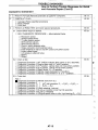
CONTENTS
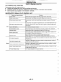
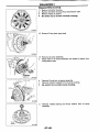
PREPARATION AND PRECAUTIONS
Special Service Tools ......................
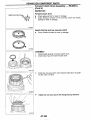
Service Notice..............................................................
Supplemental Restraint System (SRS)"AIR
BAG" ............................
DESCRIPTION...........................................
Cross-Sectional View ...
Hydraulic Control Circuits
Shift Mechanism .......................................................... 8
..................10
Control System
TROUBLE DIAGNOSES ............................................... 13
How to Perform Trouble Diagnoses for Quick
and Accurate Repair .................................................. 13
......................... 17
Remarks...
f l .........
18
Diagnostic
Diagnosis by CONSULT ............................................ 20
Preliminary Check
AlT Electrical Part
Circult Diagram for Quick Pinpoint Check.................35
........................ 36
................................ 43
Diagnostic Procedure 1 ................................
Diagnostic Procedure 2 ................................
Diagnostic Procedure 3
..................................... 85
.86
Diagnostic Procedure 4 ....................
Diagnostic Procedure 5 ............................................. 87
Diagnostic Procedure 6 ................ ........................ 88
Diagnostic Procedure 7 ................
Diagnostic Procedure 8 ............................................. 90
Diagnostic Procedure 9
Diagnostic Procedure 10 ........................................... 92
Diagnostic Procedure 11 ........................................... 93
Diagnostic Procedure 12 ........................................... 94
Diagnostic Procedure 13
....................... 95
Diagnostic Procedure 14 ........................................... 96
Diagnostic Procedure 15 ................
Diagnostic Procedure 16 ........................................... 98
Diagnostic Procedure 17 ......
Diagnostic Procedure 18 ......
Diagnostic Procedure 19 ......
Diagnostic Procedure 20 ......................................... 100
......... loo
Electrical Components Inspection
......................................... 108 :3 Ij
.................................
TROUBLE DIAGNOSES - PJT ShM Lock
...................................................... 116 -=
................................................ 1 1 6
Shift Lock Electrical Parts Location.................
Wiring Diagram .........
.................................. 117
Diagnostic Procedure
Key Interlock Cable ......................
Shift Lock Control Un
Shift Lock Control Un
Component Check .................
..............123 .ON-VEHICLE SERVICE
Control Valve Assembly and Accumulators
@
124
Inspection...............................
125
Revolution Sensor Replacement..
Rear Oil Seal Replacement..................................... 125 2,T
Parking Components lnspecti
Inhibitor Switch Adjustment ....
Manual Control Linkage Adju
Kickdown Switch Adjustment ................................... 126
REMOVALAND INSTALLATION
--I
~~
Installation............................................
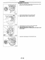
MAJOR OVERHAUL
.................................
RE4R03A ..................
.................................
129
131
.......................... 134
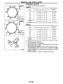
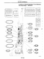
Locations of Needle Bearings, Thlust Washers
......................... ,135
and Snap Rings - RE4ROlA
Locations of Needle Bearings. Thrust Washers
and Snap Rings - RE4R03A ................................. 136
M:
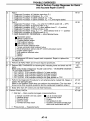
CONTENTS (Cont’d)
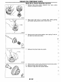
Forward Clutch Drum Assembly - RE4RCJA ........181
Rear Internal Gear and Forward Clutch Hub
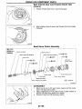
Band Servo Piston Assembly
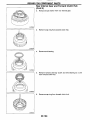
DISASSEMBLY................
........................ ,137
Disassembly....................................
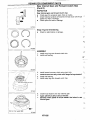
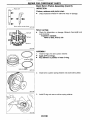
REPAIR FOR COYPONE
Oil Pump ......................
........................... 148
Control Valve Assembly ..................
Control Valve Upper Body....................................... 158
Control Valve Lower Body
........................ ,163
Reverse Clutch ............
.......................... 165
High Clutch ................
Forward and Overrun
......................... 171
Low & Reverse Brake.
Forward Clutch Drum Assemblv - RE4R01A........179
...................................
197
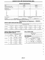
General Specifications ............................................. 211
Specifications and Adjustment - RE4ROlA........... 211
Saecifications and Adiustment - RE4R03A...........215
~
~~~
When you read wirlng diagrams:
Read GI sectlon, “HOW TO READ WIRING DIAGRAMS”.
See EL section, “POWER SUPPLY ROUTING” for power distrlbution circuit.
When you perform trouble diagnoses, read GI section, “HOW TO FOLLOW FLOW
CHART IN TROUBLE DIAGNOSES’.
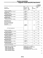
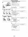
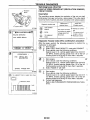
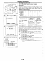
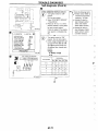
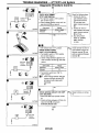
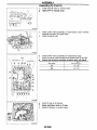
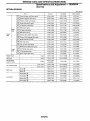
PREPARATION AND PRECAUTIONS
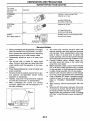
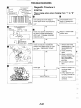
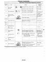
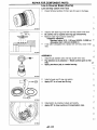
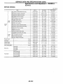
Special Service Tools
The actual shapes of Kent4
Tool number
(Kent-Moore No.)
Tool name
ire tools may differ from those of special servica tools illustrated here.
Description
,l;c
Measuring line pressure
ST2505S00t
(J34301-C)
Oil pressure gauge set
@ST25051001
.~~
J.'!.:~
( - )
Oil pressure gauge
@ST25052000
( - )
Hose
@ST25053000
( - )
Joint pipe
@ST25054000
(
-
)
Adapter
@ST25055wo
( - )
Adapter
NT097
KV31101201
Measuring line pressure
( - )
Oil pressure gauge adaptei
F.4n
-.
=
a: 44 mm (1.73 In)
b PS 118
e: PT 1/4
K1420
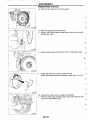
ST07870000
(J37068)
Transmission case stand
-
E
Disassembling and assembling Ary
E:
a: 182 mm (7.17 In)
b: 282 mm (11.10 In)
c: 230 mm (9.06 In)
d: 1 w mm (3.94 In)
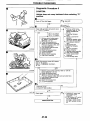
KV31102100
(J37065)
Torque cunverter one-way
clutch check tool
Checking one-way clutch in torque converter
Nrma
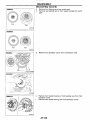
ST25850000
(J25721-A)
Sliding hammer
e
d
Removing oil pump assembly
NT422
a: 179 mm (7.05 In)
b: 70 mm (2.76 In)
c: 40
d:
M12
mm
X 1.75P
(1.57 In) din.
C
Removing and installing clutch return spnngs
KV31102400
(J34285 and
J34285-87)
Clutch spring compressor
a: 320 mm (12.W In)
b: 174 mm (6.85 In)
NT423
AT-3
Y
.
.
F;iA
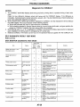
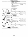
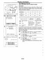
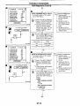
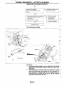
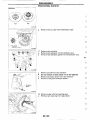
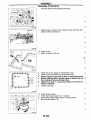
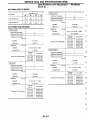
PREPARATION AND PRECAUTIONS
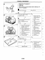
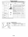
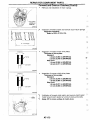
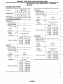
Special Service Tools (Cont'd)
Tool number
(Kent-Moore No.)
Tool name
Description
Installing oil pump housing oil seal
Installing rear oil seal
ST332MXXX)
(J26082)
Drifl
a: 60 mm (2.36 In) dla.
b: 44.5 mm (1.752 In) din.
NTWl
Installing rear oil seal
ST30720000
47%
(J34331)
Din
a: TI mm (3.03 in) din.
b: 55.5 mm (2.185 In) din.
Selecting oil pump cover bearing race and
oil pump thrust washer
(J34291)
Shim setting gauge set
KT101
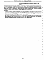
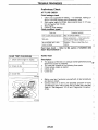
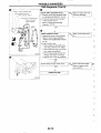
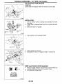
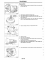
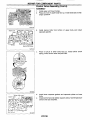
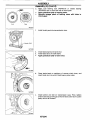
Service Notice
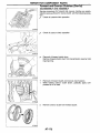
Before proceeding with disassembly, thoroughly
clean the outside of the transmission. It is important to prevent the internal parts from becoming
contaminated by dirt or other foreign matter.
Disassembly should be done in a clean work
area.
Use lint-free cloth or towels for wiping parts
clean. Common shop rags can leave fibers that
could interfere with the operation of the transmission.
Place disassembled parts in order for easier and
proper assembly.
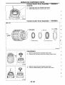
All parts should be carefully cleaned with a general purpose, non-flammable solvent before
inspection or reassembly.
Gaskets, seals and O-rings should be replaced
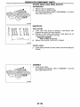
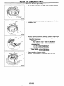
any time the transmission is disassembled.
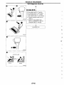
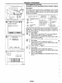
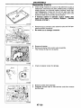
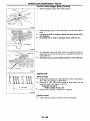
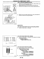
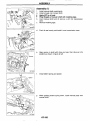
When connecting AIT control unit harness
connector, tighten bolt until red projection is inline with connector.
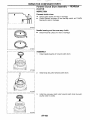
The valve body contains precision parts and
requires extreme care when parts are removed
and serviced. Place disassembled valve body
parts in order, on a parts rack, for easier and
proper assembly. Care will also prevent springs
and small parts from becoming scattered or lost.
Properly installed valves, sleeves, plugs, etc.
will slide along their bores in the valve body
under their own weight.
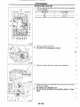
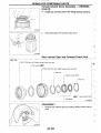
Before assembly, apply a coat of recommended
ATF to all parts. Apply petroleum jelly to protect
O-ring and seals, or hold bearings and washers
in place during assembly. Do not use grease.
Extreme care should be taken to avoid damage
to O-rings, seals and gaskets when assembling.
Flash or replace ATF cooler if excessive foreign
material is found in oil pan or clogging strainer.
Refer to TROUBLE DIAGNOSES Remarks,
AT-17.
After overhaul, refill the transmission with new
ATF.
When the AIT drain plug is removed, only some
of the fluid is drained. Old AIT fluid will remain
in torque converter and ATF cooling system.
Always follow the procedures under "Changing
AIT Fluid" in the MA section when changing AIT
fluid.
r"\,
I
Red
Protector
f
AAT151
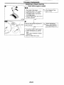
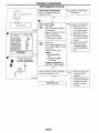
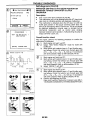
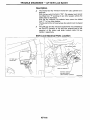
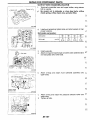
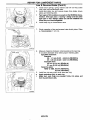
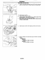
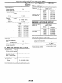
PREPARATION AND PRECAUTIONS
Supplemental Restraint System (SRS) "AIR
BAG"
The Supplemental Restraint System "Air Bag", used along with a seat belt, helps to reduce the risk or severity of injury to the driver and front passenger in a frontal collision. The Supplemental Restraint System consists of air bag modules (located in the center of the steering wheel and on the instrument panel on the pas- 6
0
senger side), sensors, a diagnosis unit, warning lamp, wiring harness and spiral cable. Information necessary
to service the system safely is included in the RS section of this Service Manual.
rI:',' '.i
WARNING:
To avoid renderlng the SRS Inoperative, whlch could increase the risk of personal injury or death
in the event of a colllslon which would result in alr bag Inflatlon, all malntenance must be performed
3:i
by an authorized NISSAN dealer.
Improper maintenance, Including Incorrect removal and lnstallatlon of the SRS, can lead to personal injury caused by unintentlonal activatlon of the system.
Do not use electrical test equipment o n any circuit related to the SRS unless instructed to in this [ :;
Service Manual. SRS wiring harnesses are covered wlth yellow insulatlon elther just before the
harness connectors or for the complete harness, for easy identiflcatlon.
.
0-
E,Z
.s. n
AT-5
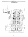
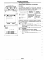
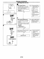
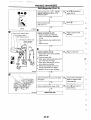
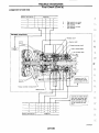
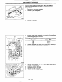
DESCRIPTION
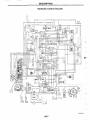
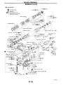
Cross-Sectional View
,
SAT218H
AT-6
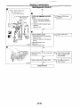
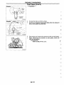
DESCRIPTION
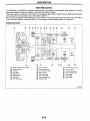
Hydraulic Control Circuits
SAT624GA
AT-7
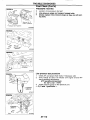
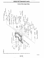
DESCRIPTION
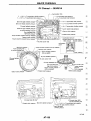
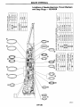
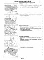
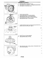
Shift Mechanism
The RE4R03A and RE4ROlA automatic transmissions use compact, dual planetafy gear systems to improve
power-transmission efficiency, simplify construction and reduce weight.
They also employ an optimum shift control and supelwide gear ratios. These improve starting performance
and acceleration during medium and high-speed operation.
Two one-way clutches are also employed: one is used for the forward clutch and the other for the low clutch.
These one-way clutches, combined with four accumulators, reduce shifting shock to a minimum.
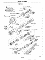
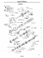
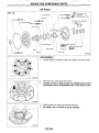
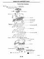
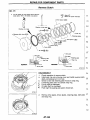
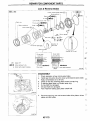
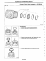
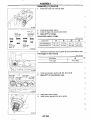
CONSTRUCTION
@
Torque converter clutch pston
8
8
8
2 Torqw converter
3 Oil pump
4
lnpuf shalt
5 Brakeband
@ Reverse clutch
7 High clrrtch
8 Front pinion gear
@
@
0
Front aun gear
Front internsl p a r
F r m t planetary carrler
Rear sun gear
Rear pinion gear
9
%
FoMard one-way clulch
8
Overrun clutch
L w oneway clutch
LW a reverse brake
Parking pawl
Farking p a r
@
Output shalt
$,
Forward clutch
SATMGH/
AT-8
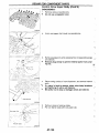
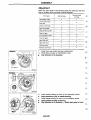
DESCRIPTION
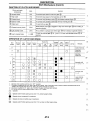
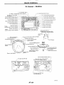
Shift Mechanism (Cont'd)
Clutch and brake
components
Funct I0n
Abbr.
@ Reverse clutch
@ High clutch
@
- Forward clutch
H/C
@ Overrun clutch
OiC
TO connect front planetary canier
0Brake band
BIB
To lock tront sun gear
RIC
FIC
@ Forward one-way clutch
F/o.c
@ LOW
U0.C
one-way clutch
@ Low & reverse brake
I
I
LgFm
To transmit input power to front sun gear
@.
_I
I TO transmrt input power to front planetary carner @
L
I To connect tront planetarv carner 0
- with forward one-wav clutch 0
@ with rear internal gear 0.
, I ,
1
@.
When forward clutch @ is engaged. to stop rear internal gear 0 from rotating in
.~
Fip.i
~
opposite direction.
At D, position. to prevent rear internal gear
I
I
To lock rear internal F a r
position).
0 (2.1,
0from rotating in opposite direction.
and 1 ?), to lock front planetary carrier
-
;
@ (R
L
~~
~~
L-
,
OPERATION OF CLUTCH AND BRAKE
Operates when overdnve swilch lo set in " O F F operam.
011 pressure is applied to bolh 2nd "appv side and 3rd "rehase" side 01 band sew0 p~slon.However. because oil pressure area on me
"release" stde is greater than lhat on the - a p W side. brake bend does not mntiact.
'3 011
pressure is applied to 4m "appV'side ~nmndltion '2 above. and brake band cmlracts.
'4 :/VI will not shift 10 41h when overdrive Switch IS sei 10 " O F F wsnion.
: operates
'1
'2
0
0
: Operates when throllle opening is less than 1116, activating engine brake.
'T
F:,
E~,T
Operates during "progressive" accelerabon.
Operates bul does not affect power transmission.
[+,
Operates when mronle opening 1s less than 1/16. but does not anect engine brake.
EL
AT-9
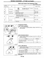
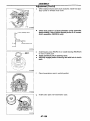
DESCRIPTION
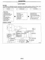
Control System
OUTLINE
The RE4ROiA and RE4R03A automatic transmissions sense vehicle operating conditions through various
sensors. They always control the optimum shift position and reduce shifting and lock-up shocks.
SENSORS
Inhibitor swltch
Overdrive switch
Throme position sensor
Closed throttle position swltCh
Wide open throttle position
swltch
Engine speed signal
Fluid temperature sensor
Revolution sensor
Vehide speed sensor
Kickdown switch
ACTUATORS
CONTROL UNIT
b
Shift control
Line pressure omtrol
Lock-up control
Overrun dutch control
Tming control
Fall-safe control
Self-diagnosls
CONTROL SYSTEM
AT-1 0
b
Shift solenold valve A
Shift solenoid valve B
Overrun clutch solenoid valve
Torque mnvelter clutch solenoid
valve
Line pressure solenoid valve
NT check indicator lamp
DESCRIPTION
Control System (Cont'd)
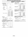
A/T CONTROL UNIT FUNCTION
The function of the AIT control unit is to:
Receive input signals sent from various switches and sensors.
Determine required line pressure, shifting point, lock-up operation, and engine brake operation.
Send required output signals to the respective solenoids.
INPUT/OUTPUT SIGNAL OF A/T CONTROL UNIT
I
Sensors and solenoid valves
I
Inhibitor switch
Function
Detects select lever position and sends a signal to A A control unit.
I
I
Detects throttle valve's fully-closed position and sends a signal to AA COntrOl
unit
Closed throttle poslhon switch
Detects throttle valve position of greater man 112 of full Ihronle and sends a s i g
Wide open mrottle position switch
nal to PA control unit. PA control unit uses the signal only when throttle sensor
maliunctions.
Input
~
From ECM (ECCS control module).
Fluid temperature sensor
Detects transmission lluid temperature and sends a signal to PA control unit
E
Vehicle speed sensor
Used as an auxiliary vehicle speed sensor. Sends a signal when revolution sensor (installed on transmission) malfunction.
.~I
;
Kickdown switch
Detects full throttle posrtion (accelerator pedal fully depressed).
Sends a signal to PA conlrol unit when throttle position sensor malfunctions.
Shift solenoid valve A/B
Selects shifting point suited to dnving conditions in relation to a signal sent from
AA control unit.
Line pressure solenoid valve
Regulates (or decreases) line pressure suited to driving conditions in relation to
a sianal sent from .&T control unit.
I
I
I AA check indicator lamp
I
-.
-.
~
i r
-
Regulates (or decreases) lock-up pressure suited to driving conditions in relation
to a signal sent from PA control unit.
Controls an "engine brake" enect suited to driving conditions in relation to a signal sent from PA control unit.
Overrun clutch solenoid valve
I~iT
I The indicator lamp blinks for about 8 seconds.
I
AT-11
,
,i",
~
E:
i
DESCRIPTION
NOTE
AT-1 2
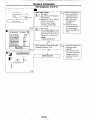
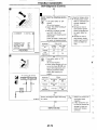
TROUBLE DIAGNOSES
~~~
~
~~
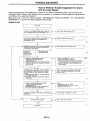
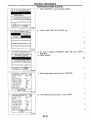
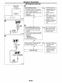
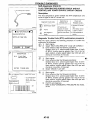
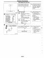
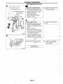
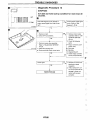
How to Perform Trouble Diagnoses for Quick
and Accurate Repair
A good understanding of the malfunction conditions can make troubleshooting faster and more accurate.
In general, each customer feels differently about a problem. It is important to fully understand the symptoms
or conditions for a customer complaint,
Make good use of the two sheets provided, "INFORMATION FROM CUSTOMER" and "DIAGNOSTIC
WORKSHEET", to perform the best troubleshooting possible.
~~
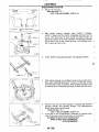
WORK FLOW
I
I
CHECK IN
LISTEN TO CUSTOMER COMPLAINTS AND FILL
OUT "INFORMATION FROM CUSTOMER. AT.14.
Reler lo FAIL-SAFE remarks. AT-17.
CHECK PA FLUID LEVEL AND CONDITION. IF
NG. PLACE CHECK ON THE DIAGNOSTIC
WORKSHEET, AT-15.
Reler lo Preliminary Check, AT.23.
No NG ilem or
NG items not
including any selldiagnostic ilems
*
NG items including
seiidiagnoslic item
-
FOR SELF-DIAGNOSIS NG ITEMS:
-INSPECT EACH COMPONENT.
-REPAIRIREPLACE.
PERFORM ROAD TEST AND PLACE CHECKS
FOR NG ITEMS ON THE DIAGNOSTIC WORKSHEET AGAIN.
--.
Refer Io selbdia nosis. AT-43
perform ROAD ?EST lor e11nems.
Prwsec if seIf-diagmS1S delecls no malfunction.
(Non-seiidiagnostic ilems. especially lhose that
require PA removal. should be repaired m VI9
follwing steps.)
I
it'
I
1
PERFORM SELF-DIAGNOSIS FOR FOLLOWING
MIL INDICATING ITEMS AND PLACE CHECKS
FOR NG ITEMS ON THE DIAGNOSTIC WORKSHEET
* IMPROPER SHlFllNG TO 1ST. 2ND. 3RD OR
4TH GEAR POSITION.
IMPROPER TORQUE CONVERTER CLUTCH
OPERATION.
Refer to EC seclion. ["Dm n m l ~
Trouble Code
(DTC)". "ON BOARD D ~ A ~ N O S T SYSTEM
IC
DESCRIPTION"].
c
ERASE DTC FROM PA CONTROL UNI
MEMORIES.
NG ,
+I
PERFORM FINAL CHECK
AT-13
Reler lo HOW TO ERASE DTC, A T 4 3
-
Reler lo Final Check. AT-IC8
;!]~l
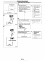
TROUBLE DIAGNOSES
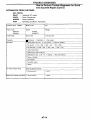
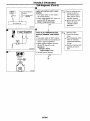
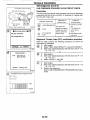
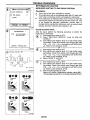
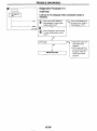
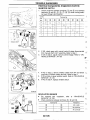
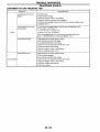
How to Perform Trouble Diagnoses for Quick
and Accurate Repair (Cont'd)
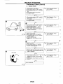
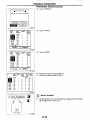
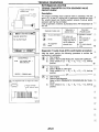
INFORMATION FROM CUSTOMER
KEY POINTS
WHAT ....... Vehicle & ,W model
WHEN ....... Date, Frequencies
WHERE .... Road conditions
HOW ......... Operating conditions, Symptoms
I
Customer name
MWMS
VIN
M1Ie age
Trans. model
RE4ROlA
RE4R03A
Engine
Incident Date
Manuf. Date
VG30DE
VG3ODETT
Frequency
Symptoms
I
Model 8 Year
Continuous
In Sewice Date
3 Intermittent (
times a day)
0 Vehicle does not move. (0Any position 0 Particular position)
", No upshift
(31st + 2nd 0 2nd + 3rd
0 No down-shift (0OiD
+ 3rd
2 3rd
+ OiDl
0 3rd + 2nd 0 2nd
--f
1st)
0 Lockup malfunction
0 Shift point too high or too low.
0 Shift shock or sliD
10 N + D
0 LockuD X Anv drive wsition)
C Noise or vibration
0 No kickdown
0 No pattern select
0 Others
1
I
Ary check indicator lamp
Blinks for about 8 seconds.
0 Continuously lit
0 Not lit
Malfunction indicator lamp (MIL) 0 Continuously lit
0 Not lit
AT-14
TROUBLE DIAGNOSES
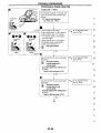
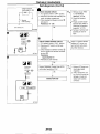
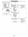
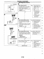
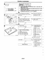
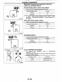
How to Perform Trouble Diagnoses for Quick
and Accurate Repair (Cont'd)
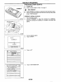
DIAGNOSTIC WORKSHEET
7 Read the Fail-safe Remarks and listen to customer comolaints.
AT-I 7
7 CHECK A A FLUID
AT-23
0 Leakage (Follow specified procedure)
0 Fluid condition
0 Fluid level
1 Perform all ROAD TEST and mark reauired procedures.
AT-23
3-1 Check before engine is started.
AT-24
0 SELF-DIAGNOSTIC PROCEDURE - Mark detected items.
0 Revolution sensor
0 Vehicle speed sensor
0 Throttle position sensor
0 Shift solenoid valve A
0 Shift solenoid valve B
C Overrun clutch solenoid valve
0 Torque converter clutch solenoid valve
0 Fluid temperature sensor and A / l control unit power source
0 Engine speed signal
0 Line pressure solenoid valve
0 Battery
0 Others
~
3-2. Check at idle
AT-25
0 Diagnostic Procedure 1 (A/T CHECK indicator lamp come on for 2 seconds.)
0 Diagnostic Procedure 2 (Engine starts only in P and N position)
0 Diagnostic Procedure 3
0 Diagnostic Procedure 4
0 Diagnostic Procedure 5
0 Diagnostic Procedure 6
0 Diagnostic Procedure 7
3-3. Cruise test
(In P position, vehicle does not move when pushed)
(In N position, vehicle moves when pushed)
(Select shock. N + R position)
(Vehicle creeps backward in R position)
(Vehicle creeps forward in D, 2 or 1 position)
AT-26
Part-1
Diagnostic Procedure 8 (Vehicle starts from D,)
0
0
0
0
Diagnostic
Diagnostic
Diagnostic
Diagnostic
Procedure
Procedure
Procedure
Procedure
12
13
14
15
(Shift schedule: Lock-up)
(Lock-up condition more than 30 seconds)
(Lock-up released)
(Engine speed return to idle. Light braking D,
+ D3)
TROUBLE DIAGNOSES
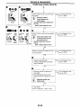
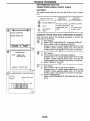
How to Perform Trouble Diaanoses for Quick
and Accurate Repair (Cont’dJ
Part-2
0 Diagnostic
0 Diagnostic
0 Diagnostic
0 Diagnostic
AT-31
Procedure
Procedure
Procedure
Procedure
Part-3
16 (Vehicle starts from D,)
9 (Kickdown: D, + D2)
10 (Shift schedule: D, + D,)
11 (Shift schedule: D, + D, and engine brake)
1
0 Diagnostic Procedure 17 D, + D, when AA CHECK switch ON
+ OFF)
AT-32
0 Diagnostic Procedure 15 Engine brake in D3)
Diagnostic Procedure 18 D, + 2 when selector lever D + 2 position)
Diagnostic Procedure 15 (Engine 6rake in 2J
Diagnostic Procedure 19 (22 (I2) + l , , when selector lever 2 + 1 position)
Diagnostic Procedure 20 (Engine brake in 1,)
SELF-DIAGNOSTIC PROCEDURE - Mark detected items.
0
0
0
0
0
Revolution sensor
0 Vehicle speed sensor
0 Throttle position sensor
0 Shift solenoid valve A
Shift solenoid valve B
0 Overrun clutch solenoid valve
0 Torque converter clutch solenoid valve
0 Fluid temperature sensor and AA control unit power source
0 Engine speed signal
0 Line pressure solenoid valve
0 Battery
0 Others
~~
~~
~
1 For self-diagnosis NG items, inspect each component. Repair or replace the
damaaed Darts.
AT-43
1 Perform all ROAD TEST and re-mark required procedures.
AT-23
1 Perform SELF-DIAGNOSIS for following MIL indicating items and check out NG
items.
Refer to EC section [“Diagnostic Trouble Code (DTC)”, “ON BOARD DIAGNOSTIC SYSTEM DESCRIPTION].
0 DTC (P0731. 1103) Improper shifting to 1st gear position
0 DTC (P0732, 1104) Improper shifting to 2nd gear position
0 DTC (P0733, 1105) Improper shifting to 3rd gear position
0 DTC (P0734. 11061 ImDroDer shifting to 4th gear position or TCC
EC
section
1 Perform the Diagnostic Procedures for all remaining items marked NG. Repair or
replace the damaged parts.
Refer to the Symptom Chart when you perform the procedures. (The chart also
shows some other possible symptoms and the component inspection orders.)
AT-I01
1 Erase DTC from A / l control unit and ECM memories.
AT-43
krform FINAL CHECK.
AT-108
0 Stall test - Mark possible damaged components/others.
0 Torque converter one-way clutch
Low & reverse brake
0 Reverse clutch
0 Low one-way clutch
0 Forward clutch
0 Engine
0 Overrun clutch
0 Line pressure is low
0 Forward one-way clutch
0 Clutches and brakes except high
clutch and brake band are OK
0 Pressure test - Suspected parts:
AT-16
AT-I 13
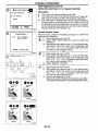
TROUBLE DIAGNOSES
Remarks
FAIL-SAFE
The Arr control unit has an electronic Fail-safe (limp home mode). This allows the vehicle to be driven even
if a major electrical inpuVoutput device circuit is damaged.
Under Fail-safe. the vehicle always runs in third gear with shift lever position of 1, 2 or D. Customer may say ''I
"Sluggish, poor acceleration".
When Fail-safe operation occurs the next time the key is turned to the ON position, the Aff CHECK indica- ,;;
tor lamp will blink for about 8 seconds. (For diagnosis, refer to AT-24.)
Fail-safe may activate without electrical circuit damages if the vehicle is driven under extreme conditions (such
as excessive wheel spins and emergency braking immediately afterwards). In this case, turn key OFF for 5
seconds and then ON to recover normal shift pattern.
The blinking of the Aff CHECK indicator lamp for about 8 seconds will appear only once and be cleared. The
,~ customer may resume normal driving conditions by chance.
L .:
Always follow the "WORK FLOW' (Refer to AT-13).
The SELF-DIAGNOSIS results will be as follows:
The first SELF-DIAGNOSIS will indicate the damage of the vehicle speed sensor or the revolution sen- E:;
sor.
During the next SELF-DIAGNOSIS performed after checking the sensor, no damages will be indicated.
d.1:~
sb,i
ATF COOLER SERVICE
Flash or replace ATF cooler if excessive foreign material is found in oil pan or clogging strainer.
VG30DENG30DEl-r engine (RE4ROINRE4R03A) ... fin type cooler
Replace radiator lower tank (which includes ATF cooler) with a new one and flush cooler line using cleaning solvent and compressed air.
OED-ll SELF-DIAGNOSIS
PJT self-diagnosis is performed by the NT control unit in combination with the ECM. The results can be
read through the blinking pattern of t h e m CHECK indicator or the malfunction indicator lamp (MIL). Refer
to the table on AT43 for the indicator used to display each self-diagnostic result.
The self-diagnostic results indicated by the MIL are automatically stored in both the ECM and WT control
unit memories.
Always perform the procedure "HOW TO ERASE DTC" on AT48 to complete the repalr and avoid
unnecessary blinklng of the MIL.
The following self-diagnostic items can be detected using ECM self-diagnostic results mode' only when
the AT CHECK indicator lamp does not indicate any malfunctions.
-Improper shifting to 1st 2nd, 3rd, or 4th gear position
-Improper torque converter clutch operation.
*: Refer to EC section ["Malfunction Indicator Lamp (MIL)", "ON BOARD DIAGNOSTIC SYSTEM
DESCRIPTION"].
AT-17
E
'34
1,jT
--
-.
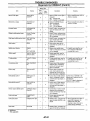
TROUBLE DIAGNOSES
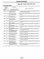
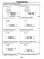
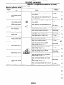
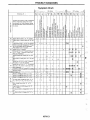
Diagnostic Trouble Code (DTC) Chart
A/T RELATED rEMS
Diagnostic
trouble code
Detected items
Malfunction is detected when
(INHIBITOR SWITCH)
switch based on the gear position.
...
PO710
1208
Fluid temperature Sensor
(FLUID TEMP SENSOR)
NT control unit receives an excessively low or high voltage from me
sensor.
PO720
1102
Revolution sensor
(VHCL SPEED SEN.ATT)
NT contrd unit does not receive the proper voltage signal from the
sensor.
PO725
1207
Engine speed signal
(ENGINE SPEED SIG)
NT control unit does not receive the proper voltage signal from the
ECM.
PO731
1103
PA can not be shifted to the 1st gear position even rf electrical circuit
is good.
PO732
1104
PO733
1105
PO734
It06
PO740
1204
Improper shifting to 1st gear posilion
(NT 1ST SIGNAL)
Improper shifting to 2nd gear position
(PA 2ND SIGNAL)
Improper shining to 3rd gear position
(PA 3RD SIGNAL)
Improper shifting to 4th gear position or TCC
(PA 4TH SIGNAL OR TCC)
TIC cluich solenoid valve
(TOR CONV CLUTCH SV)
PO745
1205
Line pressure solenoid valve
(LINE PRESSURE SN)
Ary control unit detects the improper voltage drop when it tries lo
NT can not be shifted to the 2nd gear position even if electrical circuit is good.
PA can not be shifted lo the 3rd gear position even if electrical circuit
is good.
NT can not be shifted to the 4th gear position or perform lock-up
even electrical circuit is good.
NT contrd unit detects the improper voltage drop when It tries lo
operate the solenoid valve.
operate the solenoid valve.
PO750
1108
Shift solenoid valve A
(SHIFT SOLENOIDN A)
NT control unit detech the improper voltage drop when it tries to
operate the solenoid valve.
PO755
1201
Shift solenoid valve B
(SHIFT SOLENOIDN 8)
AIT control unit detects the improper voltage drop when il tries to
operate the solenoid valve.
Pi705
1206
NT mntrol unit receives an excessively low or high voltage from the
sensor.
P17M)
1203
Throttle position sensor
Throttle position switch
(THRTL POSl SENNT)
Overrun clutch solenoid valve
(OVERRUN CLUTCH S N )
PA control unlt detects the improper vonage drop when it tries to
operate the solenoid valve.
AT-18
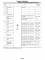
TROUBLE DIAGNOSES
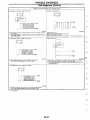
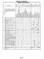
Diagnostic Trouble Code (DTC) Chart (Cont'd)
X: Applicable
-: Not applicable
ITC
'1
bnlimtion
'rocedure
h i c k Ref.
Check Items
(Possible Cause)
Reference
ail
afe
ystem
blL
lumination
2[
Page
i:;,:.
Harness or connectors
l l h e switch circuit is o w n or shorted.)
lnhibaor switch
Harness or wnnectors
(The Sensor circuit Is open or shorted.)
Fluid temperature sensor
Harness or connectors
(The sensor circuit is o w n or shorted.)
Revdunon Sensor
Harness or connectors
(The signal circuit is open or shorted.)
DRIVING
(pattern 1)
-
2 trip
AT-70
zii
X
2 trlp
AT43
L:$
DRIVING
(pattern 2)
X
2 trlp
AT49
@
DRIVING
(pattern 5 )
X
2 trip
AT46
E
Shin solenoid valve A
Shift solenoid valve E
Overrun clutch solenoid valve
Line pressure solenoid valve
Each dutch
Hydraulic control clrcuit
AT-74
?L
AT-76
2 trip
kim
AT-78
-I
=~
TIC clutch solenoid valve
~
AT40
pk
Harness or wnnectors
(The solenoid circuit is open or shorted.)
T/C dutch solenoid valve
Harness or connectors
(The solenoid circuit Is open or shorted.)
Line pressure solenoid valve
Harness or wnnectors
l l h e solenoid circuit Is o w n or shorted.)
Shift solenoid valve A
Harness or connectors
(The solenoid circuit is open or shorted.)
Shin solenoid valve E
Harness or connectors
(The sensor circuit is open or shorted.)
Throttle pasition sensor
Harness or connectors
(The solenoid circuit is open or shorted.)
Overrun ClUtch solenoid valve
'1: DRIVING pattern 1-6 means as lollows:
Pattern 1 should meet b and c.
Pattern 2 should meet a and c.
Pattern 3 should meet a through e.
Pattern 4 should meet a and b.
Pattern 5 should meet a through c.
Pattern 6 should meet a through d.
~~
IGN: ON
X
IGN: ON
X
IGN: ON
X
IGN: ON
X
DRIVING
(pattern 4)
X
IGN: ON
X
2 trip
2 trip
AT41
I
a: Selector lever is in 'D" position.
b: Vehide speed is over t o km71 (6 MPH).
c: Throttle opening is over 1/8.
d: Engine speed Is over 450 rpm.
e: A/T nuid temperature is 20 . 120°C (68- 248°F).
AT-53
q
E(T
Ki
EL
AT-1 9
TROUBLE DIAGNOSES
Diagnosis by CONSULT
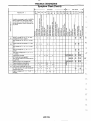
NOTICE
1. The CONSULT electrically displays shift timing and lock-up timing (that is, operation timing of each solenoid).
Check for time difference between actual shift timing and the CONSULT display. If the difference is
noticeable, mechanical parts (except solenoids, sensors, etc.) may be malfunctioning. Check mechanical
parts using applicable diagnostic procedures.
2. Shift schedule (which implies gear position) displayed on CONSULT and that indicated in Service Manual
may differ slightly. This occurs because of the following reasons:
Actual shift schedule has more or less tolerance or allowance,
Shift schedule indicated in Service Manual refers to the point where shifts start, and gear position displayed on CONSULT indicates the point where shifts are completed.
3. Shift solenoid valve "A'or "€3" is displayed on CONSULT at the start of shifting. Gear position is displayed
upon completion of shifting (which is computed by AiT control unit).
4. Additional CONSULT information can be found in the Operation Manual supplied with the CONSULT unit.
SELF-DIAGNOSTIC RESULT TEST MODE
Refer to AT-43.
DATA MONITOR DIAGNOSTIC TEST MODE
Monitor item
Item
Display
input
signals
Vehlck speed Sensor 1 (Am)
(Revolution sensor)
X
I
Description
Main
signah
-
I
Remarks
Vehicle speed computed from
signal ot revolution sensor is
diwtaved.
When racing engine in N or P
position wiih vehicle stalionary
CONSULT data mav not indicate
1s displayed
(6 rnph) It may not indlcate 0
k m (0 rnph) when vehlcle IS sta-
~
Vehicle speed sensor 2
(Meter)
X
Throttle position enso or
M R T L POS SEN
M
Fluid temperalure enso or
Battery voltage
BATrERY VOLT
M
Engine speed
PIN position Switch
R wsltlon switch
0 position W c h
2 Dosition Swilch
1 posdion s w i l d
X
-
Fluid temperature sensor signal
voltage is displayed.
Signa voltage lowers as flud
temperature nses.
X
-
Source vollage 01 control unit is
dsplayed.
FLUID TEMP SEN
Ivl
Engine spwd. computed from
engine speed signal, is dis.
played.
ENG SPEED
[rpml
X
PIN WSI sw
[ONIOFFI
X
-
ONIOFF state computed hom
signal 01 PIN posilion SW is
displayed.
R POSITION SW
[ONIOFF]
X
-
ONIOFF state computed from
slgnal of R position SW s displayed.
D POSITION SW
[ONIOFF]
X
-
2 POSITION SW
[OWOFF]
X
1 POSITION SW
[ONIOFF]
X
*
ONIOFF state computed from
signal 01 0 pOSition SW is displayed.
*
-
ONIOFF status. computed from
signal 01 2 positlon SW. displayed.
-
ONIOFF status. compuled from
signal of 1 position SW. is displayed
AT-20
Error may occur under approx.
800 rpm and meter will not mdicate 0 rpm w e n if engine is not
running.
TROUBLE DIAGNOSES
Diagnosis
by CONSULT (Cont'd)
Monitor aem
Item
I
E(
Display
I -,u,~als
DescdpIion
Main
signals
Remarks
-
* Slatus 01 ASCD CNiSe signal IS
~~
This is displayed even when no
ASCD is mounted.
displayed.
ON . . CNuIsinQ state
OFF ...
running sfate
NOA
ASCDOD cut Signal
ASCDOD CUT
[OWOFF]
Kickdown swilch
C
KICKDOWN SW
[ONIOFF]
W t h r o w poslbon s w c h
I
SHIFT S O W A
[ONIOFF]
I
ISHIFTSOWB
IOWOFF]
I
Overrun clutch solenold vabe
OVRRUWC SOW
Power Shin IamD
n
[ONIOFFI
-
POWER SHIFT
LAMP
-
HOLD SW
I
I
each input signal. 1s displayed
I
Control value cd shtt solenod
I
valve A. computed by control
una from each i n. ~ uilonal.
tis
displayed.
1
.
?..\~"
-.
1-
I
II
COntrol value Of Shin
Conhol value of sotmck IS daplayed ever! 11solenoid circuit IS
discmnected
The " O F F sigml is displayed a
solenoid circus is shorted.
valve 8. computed by control
unit lrom each input signal, is
disolaved.
. .
Control value 01 ovemn clutch
WanOtd valve computed by
mnfrol unlt from each input slgnal 1s displayed.
*
-
1
I
-
-
-
I
1
X: Appllcable
-: Not applicable
AT-21
Control status of wwer shin
lamp IS displayed.
ONIOFF stalus, computed km
Signal 01 power shtt SW, is dlsplayed.
ONIOFF status, mmplted from
s w m 01 hold SW. IS displayed.
-
1.:~:.
7 r .
ONIOFF sLBIu5. mmpuled trom
slgnal 01 hrckdwrn SW. is displayed
I
I
i-
1 POWER SHIFT SW 1
Hold swltch
-
X
> -
This is displayed even vhen no
ASCD is mounted.
Status 04 ASCDOD release
signal is displayed.
ON ... OD released
OFF ... OD not released
OWOFF stabs. computed lmm
slqnal of closed thronle witm
CLOSE THUSW
Shtt Wanad vahe A
Power Shin switch
-
X
IONIOFFI
Shin solenoid valve B
-
X
:lCp
I
Thls Is displayed even when no
power SW is.equipped. On
vehcles wlth powr SW
m n t e d on lever. vlis item is
invalid although displayed.
I
TROUBLE DIAGNOSES
Diagnosis by CONSULT (Cont'd)
Note:
1. When select ECU input signals on CONSULT, electronic control unit input signal are set.
2 . When selecting main signals on CONSULT, monitored items for understanding overall system operation are set. This sening is
indicated by a reversed display.
DATA ANALYSIS
I
Item
I
Torque converter clutch solenoid valve
duty
I
DisDlav form
I
Approximately 4%
i
ADDroximatelv 94%
Approximately 0%
Line pressure solenoid valve duty
I
Throttle position sensor
L
LOCk-UD "ON"
Low line-pressure
(Small thronle opening)
L
~
Shin solenoid valve A
I
I
Fullv-closed lhronle
Approximately 4V
Fully-open thronle
Approximately 1.5V
Cold [ZO'C (68°F))
L
L
Approximately 0.5V
Hot [8OC (176'F)J
~
Gear position
High line-pressure
(Large thronle opening)
ADDroximatelv
0.5V
..
Fluid temperature sensor
Shin solenoid valve B
Lock-up " O F F
I.
Approximately 95%
~
Meanina
~
~
~
1
2
3
4
ON
OFF
OFF
ON
ON
1
AT-22
ON
1
OFF
I
OFF
TROUBLE DIAGNOSES
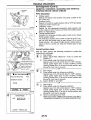
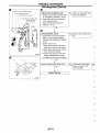
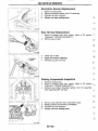
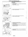
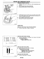
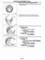
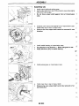
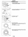
Preliminary Check
AIT FLUID CHECK
Fluid leakage check
1. Clean area suspected of leaking, - for example, mating surface of converter housing and transmission case.
2. Start engine, apply foot brake, place selector lever in "D" p s i tion and wait a few minutes.
3. Stop engine.
4. Check for fresh leakage.
Fluid condition check
Fluid color
1
/ /
~~
~
~
Sus[KcIed Droblem
Dark or black with burned odor
Wear of frictional material
Milky pink
Water contamination - Road water entering through filler lube or breather
Varnished fluid, light to dark
brown and tacky
;i
~
~~
-~
8Z
Oxidation - Over or under filling. O w healing
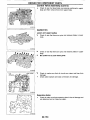
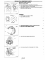
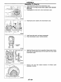
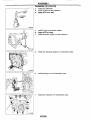
ROAD TEST
1. Check
before engine is started.
"
2. Check at idle
Description
The purpose of this test is to analyze overall performance and
determine causes of problems.
The road test consists of the following three parts:
Check before engine is started
Check at idle
Cruise test
3. Cruise test.
-L
==
~
~C
' ,=i ,
~
-.
,
Before road test, familiarize yourself with all test procedures , - - ~
and items to check.
Conduct tests on all items until specified symptom is found.
Troubleshoot items which check out No Good after road test. z i : ~
Refer to "Self-diagnosis", AT-43 and "Diagnostic Procedure",
AT-84.
-
,
SAT 4 96G
AT-23
El
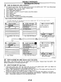
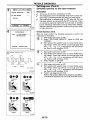
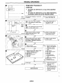
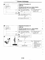
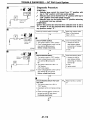
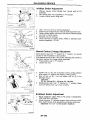
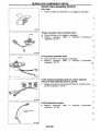
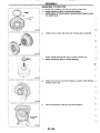
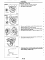
1. Check before engine
-
Is started
BB
~
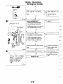
1. Park vehicle on flat surface.
2. Turn ignition switch to "OFF" position.
3. MQW selector lever to "P" w i t i o n .
4. Turn ignition switch to "ON" position.
(Do net start englne.)
5. Does AIT Check indicator lamp come on
for about 2 seconds?
SAT768B
1
Does Ary check indicato
about 8 seconds?
No
SAT194HI
Go to Diagnostic P r o w
dure 1, A T 8 4
Yes
a
l
No
I
1. Turn ignition switch to "OFF' position.
2. Perform selfdiagnosis and note NG
items.
Refer to SELF-DIAGNOSTIC PROCEDURE AT-43.
3. Go to "2. Check at idle". AT-25.
AT-24
P e r i o n self-diagnosis.
Refer to SELF-DIAGNOS
TIC PROCEDURE, A T 4 3
No
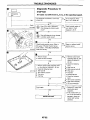
~
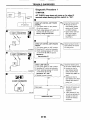
1. Park vehicle on flat surface.
2. Tum ignition switch to " O F F position.
3. Move selector lever to " P ' or " N ' position.
4. Turn ignition switch start position.
5. Is engine started?
Go to Dia nostic Procedure 2, A h 5 .
. .~
~~
.
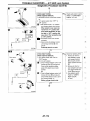
2. Move selector lever to "D', "1". " 2 or
"R" position.
3. Turn ignition switch to start position.
4. 1s engine started?
ID
dure 2. AT-85.
No
,D
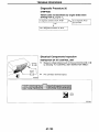
1. Turn ignition switch to " O F F position.
2. Move selector lever to "P' position.
3. Release parking brake.
4. Push vehicle forward or backward.
5 . Does vehicle move when it is pushed
forward or backward?
I
4
"es
II
Go to Dia nostic Procedure 3, AQ-85.
I
1No
4
Yes
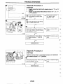
1. Apply parking brake.
Move selector lever t
SAT796.
.
Yes
~
1. Apply loot brake.
2. Move selector lever to "R" position.
Go to Dia nostic Procedure 4. A h 6
Go to Dia nostic P r m dure 5 , A&7.
J
I
L
r i
8~
I
-
i.
1. Release foot brake lor several seconds.
Go to Dia nostic Proce.
dure 6. AQ-88.
2. Does vehicle creep backward when foot
IH
brake is released?
Brake pedal
Yes
~
Yes
Go to Cruise test.
SAT797A
AT-25
No
TROUBLE DIAGNOSES
Preliminary Check (Cont'd)
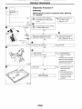
3. Cruise test
Check all items listed in Parts 1 through 3.
@
With CONSULT
Using CONSULT, conduct a cruise test and record the result.
Print the result and ensure that shifts and lock-ups take place
as per "Shift Schedule".
CONSULT setting procedure
1. Turn off ignition switch.
2. Connect "CONSULT" to data link connector for CONSULT.
(Data link connector for CONSULT is located in left dash side
panel.)
SMAIBSCI
I
Data link connector
-
_- .--?
3. Turn on ignition switch.
I
Touch "START".
5.
Touch "PA".
1
SUB MODE
I
4.
1
-
I
I
SAT974hl
SELECT DlAG MODE
0
6.
Touch "DATA MONITOR".
a
SELF-DIAG ESULTS
DATA MONITOR
ECU PART NUMBER
AT-26
TROUBLE DIAGNOSES
Preliminary Check (Cont'd)
1h
-1
I
I
I
SELECT MONITOR ITEM
MAIN SIGNALS
7.
Touch "SETTING" to set recording condition.
1
SELECTION FROM MENU
I
I
I
8 . Touch "LONG TIME" and "ENTER" key.
-L
[
SELECT MONITOR ITEM
I-1
4
ECU
I
I
I
INPUT^ IGNAI
s
--
Go back to SELECT MONITOR ITEM and touch "MAIN
SIGNALS'.
10. Touch "START'.
9.
k IT
-L
=
~
SELECTION FROM MENU
I *MONITOR
ml
*NO FAIL
ENGINE SPEED
GEAR
SLCT LVR POSI
VEHICLE SPEED
THROTTLE POSl
LINE PRES DTY
TCC SN DUTY
.1
1
N.P
Okrnlh
4%
FAIL
768rpm
Ql I
12. After finishing cruise test pari 1, touch "STOP'.
ET
~~
~
,e..
L
VEHICLE SPEED
THROTTLE POSl
LINE PRES DTY
.
~.
7~rpm-
~~
*RECORD4/8*NO
ENGINE SPEED
11. When performing cruise test, touch "RECORD".
29%
AT-27
~
TROUBLE DIAGNOSES
Preliminary Check (Cont'd)
13. Touch "DISPLAY"
REAL-TIME DIAG
* * * * NO FAILURE * * * *
I
I
SAT301(
14. Touch "PRINT"
LEVER
18:Ol
(rpm)
W'OO
0001
704
704
704
D
1
D
15. Touch "PRINT".
LEVER
l8:Ol
(rpm)
00'00
w'o1
0002
0003
704
704
18:Ol
0000
0001
0002
0003
0004
0005
704
704
D
D l
1
1
D
1
ENG GEAR SLCT
SPEED
LEVER
POSl
(rpm)
1
D
1
D
704
1
D
704
1
D
704
1
D
704
1
D
704
1
D
704
1
D
704
1
D
;E
VEHl THRTL
CLE WSI
SPEED
( k m ) (W
0
0
0
0
0
00
0.0
0.0
0.0
0.0
0
0.0
0
0
0
0.0
0.0
16. Check the monitor data printed out.
17. Continue cruise test part 2 and 3.
0.0
SAT9ffiH
I'
CLNT
35
--
@
Without CONSULT
NCOhNECER];
,a
Throttle position can be controlled by voltage across terminals
@ and @ of plrr control unit.
AT-28
TROUBLE DIAGNOSES
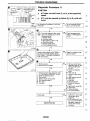
Preliminary Check (Cont'd)
Cruise test - Part 1
engine oil and ATF reach operating temperature.
ATF operating temperature:
50 - 80°C (122 - 176°F)
I
Accebrstor
Accelerator
1. Park vehicle on flat surface.
2. Set overdrive switch in "ON" position.
3. Move selector lever to "P" position.
4. Turn ignition switch to "ON" position
and start engine.
5. Move selector lever to " D posltion.
6. Accelerate vehicle at hall thronle.
7. Does vehicle start from D,?
@ Read gear position.
i
v
dure 8.AT-90.
L':
yes
Does NT shift from D, to D, at me specified speed?
Read gear posltlon.
throttle openlng and
vehicle speed.
Speclfied speed when shltllng trorn
D, to D:,
Reier to Shltl schedule. AT-33.
Go to Diagnostic ProcBdure 9. AT-91.
@
Yes
Does PJT shin from D, to D, at the specified speed?
Read gear posltlon.
throttle o p n l n g and
vehicle speed.
Speclfied speed when shlfflng from
D, t o D:,
Refer t o Shltl schedule, AT-33.
@
AT-29
No
Go to Diagnostic PrOCedure 10. AT-92.
TROUBLE DIAGNOSES
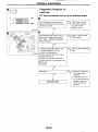
Preliminary Check (Cont'd)
1
Accelerator
WdaI
SAT402HI
1
,
vehlcle speed.
Specified speed when shifting from
D, to D,:
yes
Refer t o Shlfl schedule, AT-33.
a
(0
1
1
Does AA perform lock-up at the specified
speed?
Read vehicle speed, throitle openlng when lock-up
duty becomes 94%.
Specifled speed when lock-up
dure 12, AT-94.
@
Released
'ghtly
applid
Refer to Shift schedule. AT-33.
Does AA hold lockthan 30 seconds?
Go to Diagnostic Procedure 13, AT-95.
1 Release accelerator pedal,
2. Is lock-up released when accelerator
pedal is released?
Go to Diagnostic Procedure 14, AT-96.
brake lightly.
2. Does engine speed return to idle
smoothly when AA is shifted from D, to
dure 15, AT-97.
D?,
@
Read gear posltlon and
englnespeed.
1. Stop vehicle.
2. Go to "Cruise test - Part 2". AT-31
AT-30
TROUBLE DIAGNOSES
Preliminary Check (Cont'd)
~
~~
Cruise test - Part 2
-
2. Conlirm selector lever 1s In " D position.
3. Accelerate vehicle at halt thronle again.
I
Does vehicle start from D,7
Read gear positlon.
dure 16. AT-98.
1. Accelerate vehicle
as shown in illustration.
Go to Diagnostic Proce.
dure 9. AT-91.
i
1
2. Release accelerator pedal and then
quickly depress it fully
3. Does P A shin from D, 10 D, as soon
as accelerator pedal is depressed l u l l p
Read gear posltion and
Accelerator
Accelerator
Does AT shin trom D, to D, at the s p a -
Go 10 Diagnoslic Procedure IO.AT-92.
I =,:
--
throttle openlng and
vehicle speed.
Specified speed when shlftlng
Fully depressed
1
la
1 Release accelerator pedal afler shifting
from D, to D.,
2 Does AT shin lrom D, to D, and does
vehicle demlerate by engine brake7
@ Read gear posltlon,
throttle openlng and
vehicle speed.
2. Go to "Cruise test - Part 3 ' , AT-32.
AT-3 1
Go l o Diagnostic Procedure 11.AT-93
I
I
I
TROUBLE DIAGNOSES
Preliminary Check (Cont'd)
Cruise test - Part 3
BlEl
1. Confirm overdrive switch is in "ON"
position.
2. Confirm selector lever is in "D" position.
3. Accelemte vehicle, using half-thronle, to
Go to Diagnostic Procedure 17, AT-98.
D4.
4. Release accelerator pedal.
5 . Set overdrive swltch in " O F F position
while driving in D, posaion.
6. Does AT shift from D, to D,?
Read gear posltlon and
vehlcle speed.
@
1
0
%
I
(& (OD OFF))
Go to Diagnostic Procedure 15. AT-97.
I
0 0
1. Move selector lever from " D lo "2'
SATT76E
*
e
*
e
rcl
(D,(UP
I
Go to Diagnostic Procedure 18. AT-99.
position while driving in D.,
2. Does AT shift from D, to 2,?
@ Read gear posltlon.
-
.
Yes
UFF
Go to Diagnostic Proce
Yes
1 . Move selector lever from "2" lo "1"
position while driving in 2.,
I
(@
No
Go to Diagnostic P r m dure 19, AT-99.
.
Read gear posltlon.
~
d
I
Does vehicle demle
2. Perform selldiagnosis. Refer to SELFDIAGNOSTIC PROCEDURE, AT-43.
SAT778E
AT-32
Go to Diagnostic Procedure 20.AT-100.
I
TROUBLE DIAGNOSES
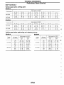
Preliminary Check (Cont'd)
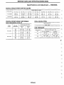
SHIFT SCHEDULE
Vehicle speed when shifting gears
RE4ROlA
I
D.
-
D,
D2
I
tian m m l s
I
1
45 - 49
(28 - 30)
Throme position
D,
-
I
D2
Full lhrome
6B - 72
(42 . 45)
Half lhrome
47 - 51
(29 - 32)
D,
-
v5 - 80)
89 . 95
( 5 5 . 59)
OD w L h
[Shill pmltlon]
position
ON
Full lbmnle
OFF
ID,l
ON
ID.1
Hall lhronle
OFF
I
ID4
I
+
-
Da
D,
D3
I
(1;:
I
I
+
32 - 38
D,
D,
+
-
D,
1 0 . 14
(6-9)
I
D,
D2
-
D,
1,
53 - 57
(33 - 35)
44-48
(27 - 30)
I
-
1,
I
I
1,
-
1W - 117
(68.73)
33 - 37
(21 - 23)
53 - 57
(33 - 35)
138. 146
(86.91)
78 - 86
(48 - 53)
28 - 34
(17-21)
10 - 14
(6 - 9)
(3-35)
167 - 175
(104 - 109)
161 - 169
(1W - 105)
107 - 115
(66.71)
9 7 . 105
(60 - 65)
119. 127
(74. 791
84 - 92
(52 - 57)
91 - 99
(57 - 62)
86 - 94
(53 - 58)
I
=I
GL
1,
177 - 187
(110 - 116)
Lock.up
"OFF'
I
'
53 - 57
(33 - 351
183-193
(114 - 120)
"ON
I
D,
D,
(20 - 24)
I
D.
-
97 - 105
(60 - 65)
1 6 0 - 170
(99- 106)
~.
2
53 - 57
Vehicle speed kmih (MPH)
speed km/h (MPH)
Lmk-UP
P1
.
D.
(74 - 79)
D,
120 - 128
D,
119- 127
1
D3
-
166. 176
(103- 10-3)
1
82-88
(51 - 5 5 )
Veh&
Thronle
D,
D,
107. 115
(66 - 71)
60.64
(37 - 40)
Full ~ r o n l e
-
Vehicle sowd kmih M P H I
OD switch
Thronls
pasilton
Full ulronle
.
I
Half throme
Lock-UP
"ON"
Lock-up
"OFF
ON
lD.1
184 - 192
(114. 119)
OFF
ID,I
120 - 128
(75 - 80)
ON
ID,]
184 - 192
(114 - 119)
117 - 125
(73 - 78)
OFF
IDJ
88 - 96
(55 - 60)
74 - 82
(46 - 51)
178 - 186
- 116)
;.-.
(111
iw -
117
(68 - 73)
~i :I
...
1-
I
AT-33
[Shin pasaim]
1
~
TROUBLE DIAGNOSES
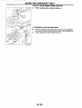
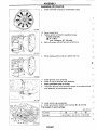
AIT Electrical Parts Location
solenoid valve
Fluid temperature
Overrun clutch
SAT7331
AT-34
~~
TROUBLE DIAGNOSES
Circuit Diagram for Quick Pinpoint Check
TO t a c h o m e t e r
LINE PRESSWE SOLENOIO
11,
OVERRUN CLUTCH SOLENOID
VALVE
m
REVOLUTION SENSOR
~I 1
A/T
-
_ -- - - - _
I ,
c
"7
m
I-m-,l
FLU10 TEMPERATURE
SHIFT SOLENOIO VALVE B
SHIFT SOLENOIO VALVE A
w
m
m
3
t
U
LL
W
C
Q
.
TOROUE CmVERTER
CLUTCH SO-ENUID VALVE
m
+
w
STOP LAMP SWITCH
m
A
8
-
I
..
rn
.J
KICKDOWN SWITCH
I.
+
I
z
3
J
0
U
r
2
0
V
..
r
4
A/T
CHECK
IN~ICATW
LAMP
+
J
Y U 3
ZOO?
-+z
JVO
W"
az
CZU
eo0
OVLL
Ln
0
+
+o -m
HAT010
AT-35
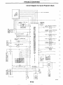
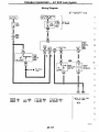
TROUBLE DIAGNOSES
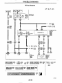
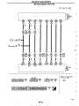
Wiring Diagram
I
I G N I T I O N SWITCH
ON o r START
Y
I
1
I
1
AT-A/T-0
I
L
I
0
0
I
G
I
7y/G
Y/G
G
G
*Next
page
To AT-
*A/T-06
COMBINATION
METER
QE3
SPEEWMETER
P
GY
.
Y/B
L
Y/B
L
Y/B
L
m
rn
B
I
Am3
P
Wm-- V
I
To AT-
I
G/L
Y/B
r"
COFCTROL
WIT
Refer to last page
(Foldout p a g e ) .
I
I
I
rn:
I
I
w :
I
HAT003
AT-36
TROUBLE DIAGNOSES
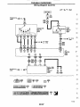
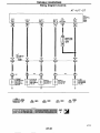
Wiring Diagram (Cont'd)
AT-37
TROUBLE DIAGNOSES
Wiring Diagram (Cont'd)
AT-A/T-03
ECCS
IDLE
VB-R
AVCC
LG/R
G/R
OWL
w
- A GND-C
GNO-C
B
B
'I
I
-0-0
I
W
I
LG/R
I
LG/B
It
OWL
A/T
CONTROL
UNIT
0
,
'
Refer t o last page
(Foldout Page)
.
cm
HAT005
AT-38
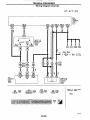
TROUBLE DIAGNOSES
Wiring Diagram (Cont’d)
AT- A/T-0 4
A/T
CCNTROL
UNIT
HAT036
AT-39
TROUBLE
.
_ _ _ _ DIAGNOSES
~~
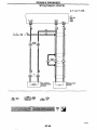
Wiring Diagram (Cont'd)
AT-A/T-05
r
Lf
s€Ns
ID
i
g
TO ATA/T-03
*
-
I
=
I
I
-
1
REVOLUTION
SENSOR
I
HATW7
AT-40
Y/G
TROUBLE DIAGNOSES
Wiring Diagram (Cont'd)
AT-A/T-06
ECM
(ECCS
C0NT R0L
WIT)
b
[
I
I
+
I'
Y/G
0
Y/G
TO
AT-
A/T41
-I
4 Y/G
To
tachometer
+
c
Y/R
6
I
0
I
I
)---I
I
I
.
-
I
F
--ij
t---i
F
1
F
u
lic
Tk
I
g
\m
-7
A/T
F a f e r t o last page
(Foldout p a g e ) .
0
I
HATMB
AT-41
TROUBLE DIAGNOSES
Wiring Diagram (Cont'd)
AT- A/T-07
F
I A/l
C ~ R O L
0
C
I I
s
S
iY
SI
T
A
SI
I
I!
I I
I
P
n
D
I
A/T
SOLENOID
VALVE
*2
ri
I
r[
CONVERTER
VALVE 8
SOLENOID
VALVE
J
L
[
HATWS
AT-42
~
~~
TROUBLE DIAGNOSES
-
1
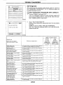
Self-diagnosis
After performing this procedure, place check marks for results on
the "DIAGNOSTIC WORKSHEET", AT-I5 Reference pages are
provided following the items
@ SELF-DIAGNOSTIC
PROCEDURE (With CONSULT)
7
)
1
71
Turn on CONSULT and touch "NT"
If A/T is not displayed, check PJT control unit power supply and
ground circuit. Refer to AT-101. If result is NG, refer to EL section ("POWER SUPPLY ROUTING").
'
~
~
FAILURE DETECTED
THROTTLE POSl SEN
Touch "SELF-DIAG RESULTS".
Display shows malfunction experienced since the last erasing
operation.
CONSULT performs REAL-TIME SELF-DIAGNOSIS.
Also, any malfunction detected while in this mode will be displayed at real time.
~~
.
~~
~~
,F
,L
,
--_
~
L
1 .
TIC clutch Solenoid vabe
(TOR CONV CLUTCH SV)
IVT mntrol unit detects the improper voltage drop when it
tries to operate the wlenod wive.
X
X
Line pressure solanoid vake
(LINE PRESSURE S N )
AIT control unit detects the imprwer vallage drop when 11
X
X
ThrotUe psilion sensor
Throme pasition Switch
(THRTL POSl SEN.AIT)
A A control unlt re~eivesan excessively low or high voltage tmm h e sensor.
X
X
Engine speed sgnal
(ENGINE SPEED SIG)
Nl control unit does not receive the proper vonage slgnal from the ECM.
X
X
he85 lo Operate the solenoid valve.
TROUBLE DIAGNOSES
Self-diagnosis (Cont'd)
I
Indicator lor Diaonoslic R e w k
I
Detecled items
Malfunctionk detected when ...
(Scrwn t e r n lor CONSULT,
"SELF.DIAG RESULTS mode)
-
Fluid temperature sensor
(FLUID TEMP SENSOR)
Initial slarl
INITIAL START
/VI CHECK
indicator lamp
(Avallable when
' ' P U T on CONSULT
19
AIT conlrol unit receives an excessively low or hlgh voltage from the sawor.
touched 1
Mallurdion
indlcatw lamp'2
(Available when
"ENGINE on CONSULT IS l o h d . )
X
X
X
X
This is not a rnanunctim message (Whenever shuning ot
a power supply to the control unit this message appears
I
No tailure
(NO SELF DIAGNOSTIC FAILURE INDI-
I'
CATED
FURTHER TESTING MAY BE
REQUIRED"I
m the a r r a ~ . \
I
No failure ha5 besn detected.
I
- : Not applicable
'1 : These malfunctions can not be displayed by MIL
if another mallunction is assigned to the PIT CHECK indicator lamp
["Malfunction Indicator Lamp (MIL)", "ON BOARD DIAGNOSTIC SYSTEM DESCRIPTION"].
CODESffREUE
1
Scan Tool (GST)]
Refer to EC section ["Generic Scan Tool (GST)", "ON BOARD
DIAGNOSTIC SYSTEM DESCRIPTION"].
THROTrLE POS
MALFUNCTION
1705
[ENTER] *FREEZE DATA
SAT254H
I
@ SELF-DIAGNOSTIC PROCEDURE (No Tools)
DIAGNOSIS START
I
I
l
SA T g n F i
,
ch
u\J'-Afl
I
t\
lamp
n
\
i
SAT194HA
1. Start engine and warm rt up to normal
engine operating temperature.
2. Turn ignition switch to "OFF' position.
Wait at least 5 seconds.
3. Turn Ignition switch from "OFF' to
" A C C position.
4. Set overdrive switch in "OFF' posrtion.
5. Move selector lever to "D" position.
6. Turn ianitlon switch to "ON" wsition.
(Do not start engine.)
7. Does AfI check indicator lamp come on
tor about 2 seconds?
I
Go l o Diagnostic Procedure 1. AT-84.
I
TROUBLE DIAGNOSES
Self-diagnosis (Cont'd)
1
I
I
'
11
8. Move selector lever to ''2 position.
SAT978FII
I
9. Set overdrive switch in " O N position.
10. Move selector lever l o "1" position.
11. Set overdrive switch in "OFF' position.
12. Depress accelerator pedal fully and
release it.
13. Check P f r check indicator lamp
Refer to JUDGEMENT OF SELF-DIAGNOSIS CODE on next page
DIAGNOSIS END
SATWFI
I3
Accelerator pedal
AT45
,.
I
TROUBLE DIAGNOSES
Self-diagnosis (Cont’d)
JUDGEMENT OF SELF-DIAGNOSIS CODE
I
Flickers 01 Ail check induator lamp: Damaged circuil
All judgemenl flickers are same.
U? judgemenl Ilcker is longer then olhers.
,
SAT:
,hdi solemld vabe A ~ r c u iISl shoncircuiled or dlsmnnected
+ G O Io shln solenold valvo A CI~CYII
check. AT-55.
1st judgement nlcker is longer than others.
1
Revoluuon sensor c i r ~ u lISl shalfclmiled or dismnnected
+ GO IO reVolUllon BOT ~ l m u l Check.
t
AT-49.
I 2 n d judgement flicker
IS
th judgement flicker 4s longer than omers
SATZ77C
Ih judgement flicker is longer than others
longer than others
,
3rd judgement flicker is longer than omers
th judgement lluker IS h g e r than o h r s
,
SAT290C
Thronle posltlon sensor circuil 86 SholfarCUned or disconnected
+ GO to thmllle poslllon Ben807 ClrCYlt check. AT-53.
t, = 2.5 seconds
,t = 2 0 seconds
t, = 1 0 second
AT-46
TROUBLE DIAGNOSES
Self-diagnosis (Cont'd)
Flickers 01 IVI check indimlor larnP Darnaqed clrcult
1 Flickers as shown below.
,Ih ludgerncnt llicker is longer than olhers
Self-diagnosls
n
-Light
+Shade
j~Llght
c
Shade
SATZ'lG
luid temperature sensor 85 disconnected or &T m t r d unit power source cirdit 8s damaged
Go l o lluld temperature sonsor and M control unll power murce clrCull Check, AT43.
Ranery power 8s low
Banery has been diYOnnened lo( a long time
Banely 85 cmnected conversely
(When reconnechng Arr conirol unn m n n m m -This
lh judgement flicker 1s longer than others
DOBSnot come on
.
I
SAT224G
ine pressure solenoid valve C ~ ~ C U8s~ Shm-clrcu#IBO
I
or disconnected
Go lo llne pressure eolenold valve cI~cuII
check. AT-.
td = 1.O second
SATZWG
s mi a problem j
TROUBLE DIAGNOSES
Self-diagnosis (Cont'd)
@
HOW TO ERASE DTC (With CONSULT)
If the ignition switch stays "ON" after repair work, be sure to turn ignition switch "OFF" once. Wait at least
5 seconds and then turn it "ON" (engine stopped) again.
Turn CONSULT "ON", and touch " A T ' .
Touch "SELF-DIAG RESULTS".
Touch "ERASE". (The DTC in the A A control unit will be erased.)
Touch "BACK' twice.
Touch "ENGINE".
Touch "SELF-DIAG RESULTS".
Touch "ERASE". (The DTC in the ECM will be erased.)
1.
2.
3.
4.
5.
6.
7.
8.
How to erase DTC (With CONSULT)
1
b
If the ignition switch stays ON aner repair work be sure 10 turn ignition Switch OFF once Walt at least 5 seconds
and then turn 11 ON lengine stopped1 again
SELECT SYSTEM
ENGINE
An
SELF-DIAG RESULTS
FAILURE DETECTED
DATA MONITOR
SHIFT SOLENOIDN A
0
~
ECUPARTNUMBER
I
]
P A q - 1
2
Turn CONSULT 'or.
and touch
3
Touch YjELF-DIAG RESULTS
4
'AT.
b
SELECT SYSTEM
ENGINE
An
b
SELECT DlAG MODE
Touch 'ERASE" (The DTC In the
&
mtrd
'l
unlf mll be 9 4 )
SELF-DIAG RESULTS
I0
WORK SUPPORT
SELF-DIAG RESULTS
SHIFT SOLENOIDN A
10
7
DATAMONITOR
ACTIVE TEST
FUNCTIONTEST
5
Touch 'ENGINE'
FREEZE FRAME DATA
6
T m h 'SELF DlAG RESULTS'
(ERAFI(I
7
Touch "ERASE' (The DTC In the
ECM wdl be erased)
SEF3380
@
HOW TO ERASE DTC [With Generic Scan Tool (GST)]
Select Mode 4 with Generic Scan Tool. For details, refer to EC section, "Generic Scan Tool (GST)". "ON
BOARD DIAGNOSTIC SYSTEM DESCRIPTION".
HOW TO ERASE DTC (No Tools)
1
3
1. If the ignition switch stays "ON" after repair work, be sure to turn ignition switch "OFF' once. Wait for at
least 5 seconds and then turn it "ON" (engine stopped) again.
2. Perform "SELF-DIAGNOSTIC PROCEDURE (No Tools)" on AT-44. (The engine warm-up step can be
skipped when performing the diagnosis only to erase the DTC.)
3. Change the diagnostic test mode from Mode II to Mode I by turning the mode selector on the ECM.
Refer to EC section ["HOW TO SWITCH DIAGNOSTIC TEST MODES", "Malfunction Indicator Lamp
(MIL)", "ON BOARD DIAGNOSTIC SYSTEM DESCRIPTION"].
AT-48
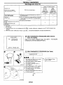
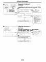
TROUBLE DIAGNOSES
Self-diagnosis (Cont'd)
Diagnostic trouble code
SAT3381
@:
VHCL SPEED
SENNT
@:
PO720
fi&
FAILURE DETECTED
'w
VHCL SPEED SEN-IVT
,
'
lstjudgernent
flicker
,.
Check item
(Possible cause)
Malfunction is
detected when ...
:
,~
~=
Harness or connectors
(The sensor circulf
is open or shod.)
Revolution sensor
AA control unit does
not receive the proper
voltage signal from
me sensor.
I
Diagnostic Trouble Code (DTC) confirmation procedure
CODESlFREEZE
07x)
1
VEHICLE SPD
MALFUNCTION
1
[ENTER] 'FREEZE DATA
SAT2561
\
\ I //,
Revolution sensor
After the repair, perform the following procedure to confirm the
malfunction is eliminated.
1) Start engine.
2) Select "SELF-DIAG RESULTS" mode with CONSULT
3) Drive vehicle under the following conditions:
Selector lever in D, vehicle speed higher than 30 k m h
(19 MPH), throttle opening greater than 1/8 of the full
throttle position and driving for more than 5 seconds.
OR
@ I ) Start engine.
2) Drive vehicle under the following conditions:
Selector lever in D. vehicle speed higher than 30 k m h
(19 MPH), throttle opening greater than 1/8 of the full
throttle position and driving for more than 5 seconds.
3) Select "MODE 3 ' with GST.
OR
@ 1) Start engine.
2) Drive vehicle under the following conditions:
Selector lever in D, vehicle speed higher than 30 krn/h
(19 MPH), throttle opening greater than 118 of the full
throttle position and driving for more than 5 seconds.
3) Perform self-diagnosis.
Refer to SELF-DIAGNOSTIC PROCEDURE (No Tools),
AT-44.
pz
,
1
~~
1.p
--
I
.
ii"
E.
r~:
FL'~
~~
L'K
Ll'
~~
I
1
SAT0251/
AT49
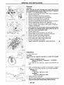
TROUBLE DIAGNOSES
Self-diagnosis (Cont'd)
Revdution 18mor
CHECK REVOLUTION SENSOR.
Refer to "Electrical Components
Inspection". AT-105.
Repair or replace revolution sensor.
OK
ov
I
NG
CHECK INPUT SIGNAL.
1. Start engine.
2. Select "ECU INPUT SIGNALS'
~ T T c o n t r ounit
l
AIT control unit termind
Check the following items:
Harness for short or
open between Ary control unit and revolution
sensor (Main harness)
Harness lor short or
open between revolution
sensor and ECM (Main
harness)
Ground circuit for ECM
Refer to EC section
("TROUBLE DIAGNOSIS FOR POWER SUPPLY").
I
At 30 k m h (19 MPH):
1V or more
(Voltage rises gradually In
response to vehlcle speed.)
OK
Perform Diagnostic Trouble Code (DTC)
confirmation procedure. AT-49.
-
OK
SAT259HB
AT-50
NG
1. Perform AA control unit
inputioutput signal
inspection.
2. If NG. recheck AA control unit pin terminals for
damage or loose connection with hamess
connector.
TROUBLE DIAGNOSES
Self-diagnosis (Cont'd)
I
/
VEHICLE SPEED SENSOR.MTR CIRCUIT CHECK
Description
The vehicle speed sensorMTR is built into the speedometer
assembly. The sensor functions as an auxiliary device to the revolution sensor when it is malfunctioning. TheMcontrol unit will then
use a signal sent from the vehicle speed sensorMTR.
:;ju
~~
."..
Diagnostic trouble m d e
I
1
Malfunchon is
detected when ...
SAT1721
VHCL SPEED
SENMTR
I /
IFAlLURE DETECTED
2nd judgement
flicker
A A control unlt does
not receive the proper
vonage signal from
the sensor.
Check item
(Possible cause)
Harness or connectors
(The sensor circuit
is open or short.)
Vehlcle speed s e n -
-.
I
~
Diagnostic Trouble Code (DTC) confirmation procedure
After the repair, perform the following procedure to confirm the E
malfunction is eliminated.
1) Start engine.
2) Select "SELF-DIAG RESULTS' mode with CONSULT. 'SL
3) Drive vehicle under the following conditions:
Selector lever in D and vehicle speed higher than 20
km/h (12 MPH).
%$T
OR
I ) Start engine.
2) Drive vehicle under the following conditions:
Selector lever in D and vehicle speed higher than 20
k m h (12 MPH).
I'I,
3) Perform selfdiagnosis.
Refer to SELF-DIAGNOSTIC PROCEDURE (No Tools),
AT-44.
, .
,~
@I
1s
longer Inan olhers.
\ I ///
'/I
\ \
-
Vehicle speed
sensor
meter
--~
-
A.
..
AT-51
TROUBLE DIAGNOSES
Self-diagnosis
(Cont'd)
CHECK INPUT SIGNAL.
IG
4
Combination
2.Select "ECU INPUT SIGNALS'
in Data Monitor.
3. Read out the value of "VHCUS
SE.MTR" while driving.
Check the value changes
according to driving speed.
senso<
AI? control "nil
1. Start engine.
2. Check voltaae between AA con-
B
VHCUS S E M R
MRTL POS SEN
FLUID TEMP SE
BATrERY VOLT
ENGINE SPEED
:heck the following items:
Vehicle speed sensor
and ground circuit for
vehicle speed sensor
Refer to EL section
("METERS AND
GAUGES').
Harness for short or
open between AA control unit and vehicle
speed Sensor (Main harness)
Voltage:
13.4V
OVERDRIVE SW
P/N POSl SW
R POSITION SW
Perform Diagnostic Trouble Code (DTC)
confirmation procedure, AT-51.
RECORD
SAT1711
OK
21
j
YIG
AT-52
NG
I . Perform AA control unit
inpuVoutput signal
inspection.
2. It NG, recheck AA control unit pin terminals for
damage or loose connection with harness
connector.
TROUBLE DIAGNOSES
Self-diagnosis (Cont'd)
THROlTLE POSITION SENSOR CIRCUIT CHECK
Description
The throttle position sensor detects the throttle valve position and
sends a signal to the M control unit.
Diagnostic trouble code
@:
@:
p,
,
w.
FAILURE DETECTED
r
CODESFREEZE
1705
1
MROTTLEPOS
MALFUNCTION
3;HFlTLE POSIPI075
3rd judgement
flicker
Malfunction is
detected when ...
/vT m t r o l unit
receives an excessively low or high voltage from the sensor.
Check item
(Possible cause)
9
Harness or connectors
(The sensor circuit
is open or short.)
Throttle position
sensor
Diagnostic Trouble Code (DTC) confirmation procedure
After the repair, perform the following procedure to confirm the
malfunction is eliminated.
1) Start engine.
2) Select "SELF-DIAG RESULTS" mode with CONSULT.
3j Drive vehicle under the following conditions:
Selector lever in D, vehicle speed higher than 10 kmih
(6 MPH), throttle opening greater than 1/2 of the full
throttle oosition and driving
- for more than 3 seconds.
;;IT
OR
,
@ 1 ) Start engine.
2) Drive vehicle under the following conditions:
Selector lever in D, vehicle speed higher than 10 kmih :~
(6 MPH), throttle opening greater than 1/2 of the full
throttle position and driving for more than 3 seconds.
1;,;'
3) Select "MODE 3" with GST.
OR
@ I ) Start engine.
?;
2) Drive vehicle under the following conditions:
1 .-~
Selector lever in D. vehicle speed higher than 10 km/h
(6 MPH), throttle opening greater than 1/2 of the full
throttle position and driving for more than 3 seconds.
1. : ~ ~.
3) Perform self-diagnosis.
Refer to SELF-DIAGNOSTIC PROCEDURE (No Tools), ~.
E',k;
AT-44.
d l
1
[ENTER] 'FREEZE DATA
S
!54t
-
~
@ 3rd ludgemenl flicker
.\ \ I / / /
IS
longer than others
0:
/ / I \ \
/
,-Throttle
position sensor
r{
k,,:'~
1-
I
SAT0271
-~
-''~1'
AT-53
TROUBLE DIAGNOSES
Self-diagnosis (Cont'd)
Throttle position sensor
Perform diagnostic test mode II
diagnoshc results) for engine control
Refer to EC section 1"Maltunction Indicator
Lamp (MIL)". "ON BOARD DIAGNOSTIC
SYSTEM DESCRIPTION"].
1
35
34
.OK
31
A i l conlrol unit
SAT34e
:HECK INPUT SIGNAL,
1. Turn ignition switch to "ON'
wsition.
(Do not start engine.)
2. Select "ECU INPUT SIGNALS'
in Data Monrtor
3. Read out the value of "THRTL
POS SEN".
V
MONITOR
VHCUS SE-AT
VHCUS SE-MTR
THRTL POS SEN
FLUID TEMP SE
BATTERY VOLT
ENGINE SPEED
OVERDRIVE SW
PIN POSl SW
R POSITION SW
sor circud lor engine control Refer to EC section
["Throttle Position Sensor
(DTC : 0403)". "TROUBLE
DIAGNOSIS FOR DTC
POlZO'].
%?
NOFAIL
Oh*
5k1wT
I
open between ECM and
AA conlrol unit regarding
throttle position sensor circuit. (Main harness)
0.5V
0.6V
13.4V
763rpm
OFF
ON
OFF
RECORD
4117
Refer to "Self-diagnosis", "CHECK KICKDOWN SWITCH CIRCUIT", AT-72.
AT-54
parts.
I
Gear position
1
2
3
4
Shift solenoid
valve A
ON
OFF
OFF
ON
~~
~
, ,
~
Shift solenoid
valve B
SHIFT SOLENOIDMA
ON
Diagnostic trouble code
(@ : t2Fr SOLENOID/
(@'
__
-
"0 ,
'rooLI!
~
CODEWREUE
0750
: PO750
4th ludgement
:
llicker
ON
Malfunction is
detected when ...
PJT control unit
detects the improper
voltage drop when it
tires to operate the
solenoid valve.
OFF
OFF
Check item
(Possible cause)
~
8-
, z ..
~
Harness or connectors
(The solenoid cir.
cui1 is open or
short.)
Shift solenoid valve
A
~
1
SHIFT S N A
MALFUNCTlON
,~
Diagnostic Trouble Code (DTC) conflrrnation procedure
After the repair, perform the following procedure to confirm the
malfunction is eliminated.
1) Start engine.
2) Select "SELF-DIAG RESULTS" mode with CONSULT. I~ 7
3) Drive vehicle in D, + D, position.
OR
-~
,G@l
~- 1) Start engine.
2) Drive vehicle in D, + D, position.
3) Select "MODE 3" with GST.
,
OR
.~
&
1) Start engine.
.~
2) Drive vehicle in D, + D, position.
3) Perform self-diagnosis.
Refer to SELF-DIAGNOSTIC PROCEDURE (No Tools),
AT-44.
=-
1
~
0
[ENTER] 'FREEZE DATA
:
:8
~
~~
1691
s: : ,
4fh ludaement timer
.\ I
8s longer lhan olhe1s
/I,
,
0' / I
I
~~
~~
\ \
Self-diagnosis
~~
Shill soIeno#d
valve A
~~
~~
Light
1
;
Shade
SAT02811
AT-55
TROUBLE DIAGNOSES
Self-diagnosis
(Cont'd)
.
Shin solenoid &e
A
1, Tum ignition SwitCh to "OFF' posltlon.
2. Diswnnect terminal cord assembly connector in engine cwnpartrnent.
3. Check resistance between terminal @
and ground.
Realstance: 20 40R
TsmmaI
assembly
t
-
AIT control unit
SAT67OG
I
I
Solenold
r
1. Remove control valve
assembly. Refer lo "ONVEHICLE SERVICE,
AT-124.
2. Check the following
items:
Shlft solenoid valve A
(Refer to "Electrical
Components Inspection".
AT-107.)
Hamess of terminal cord
assembly for short or
open
I
connector@
NG
CHECK POWER SOURCE CIRCUIT.
1. Turn ignition switch to "OFF' position.
2. Disconnect PJT control unit harness
connector.
3. Check resistance between terminal @
terminal
Repair or replace harness
between IVT control unit
and terminal cord assembly. (Main harness)
@.
Reslatance:
Approxlmately
On
4. Reinstall anv Dad removed
Solenoids
harness
conneclor
Perform Diagnostic Trouble Code (DTC)
confirmation procedure. AT-55.
a
T
II
INSPECTION END
AT-56
I
1. Perform IVT control unit
inpuVoutput signal
inspection.
2. If NG. recheck /vT control unit pin terminals tor
damage or 10058 connection wim harness
connector.
TROUBLE DIAGNOSES
Self-diagnosis (Cont'd)
Line pressure solenoid valve
I
I
7
Shift soienoid valve B 7
SHIFT SOLENOID VALVE B CIRCUIT CHECK
Description
Shift solenoid valves A and B are turned ON or OFF by the A A
control unit in response to signals s6nt from the inhibitor switch,
vehicle speed and throttle position sensors. Gears will then be 31
shifted to the optimum position.
Gear Dosition
L
Loverrun Clutch soleno~dvalve
Shift solenoid
valve A
SAT0011
I
1;1
I
1
I
I N
2
I
1
I
3
OFF
OFF
valve B
I
I
4
ON
'I,:
=
~
:I
OFF
i
I
L
~.
FAILURE DETECTED
Malfunction is
detected when
Diagnostic trouble code
@ :F
r;;
'$3''
. :
A A control unit
detects the improper
voltage drop when It
tires to operate the
solenoid valve.
PO755
C0,
5th judgement
~!!OOL3~
~.: flicker
CODESFREEZE
0755
1
SHIFT W E
MALFUNCllON
Harness or connectors
(The solenoid circuit IS open or
short.)
Shift solenoid valve
SOLENOID/
~/
~
Check item
(Possible cause)
~~~~
~~~
I
E
:L
R
~
a:1 1
Diagnostic Trouble Code (DTC) confirmation procedure
After the repair, perform the following procedure to confirm the -.
malfunction is eliminated.
1 ) Start engine.
2) Select "SELF-DIAG RESULTS" mode with CONSULT. ~1
3) Drive vehicle in D, --f D, + D, position.
OR
@
I: , :
1) Start engine.
F:i
2) Drive vehicle in D, + D, + D, position.
3) Select "MODE 3' with GST.
OR
--
1
~
@
[ENTER] 'FREEZE DATA
x - 1
c
"
I$;
5th Judgement fllchef
IS
'73
longer than Others.
~
2)
' / I
\ \
~
Shift M l e m d valve B
3)
Drive vehicle in D, + D, --f D, position.
Perform self-diagnosis.
Refer to SELF-DIAGNOSTIC PROCEDURE (No Tools),
AT-44.
AT-57
TROUBLE DIAGNOSES
Self-diagnosis (Cont'd)
]El
-
Shm solenold valve B
CHECK GROUND CIRCUIT.
1. Tum ignition switch to "OFF position.
2. Disconnect terminal cord assembly connector in engine compartment.
3. Check resistance between terminal @
and ground.
Terminal
cord BSSembly
Realstance: 20 - 40R
1. Remove control valve
assembly. Refer to "ONVEHICLE SERVICE,
AT. 124.
2. Check !he following
items:
Shin solenoid valve B
(Refer to "Electrical
Components Inspection".
AT-1 07.)
Harness of terminal cord
assembly for shod or
I
OK
o w
Solenoids
harness
RCE CIRCUIT.
1. Turn ignition switc to "OFF position.
2. Disconnect P A control unit harness
connector.
3. Check resistance between terminal @
and Afl control unit harness connector
terminal
Resistance:
Awmximately OC1
4. Reinstall any part removed.
dl
SAT1571
0.
Solenoids
harness
conneclor
confirmation procedure. AT-57.
OK
I
INSPECTION END
CONluECTOR
WNlT
Repair or replace h a m s
between Afl control unit
and terminal cord assembly. (Main harness)
I
AT-58
1. Perform A f l control unit
inpuVoutput signal
inspection.
2.If NG,recheck Afl control unit pin terminals for
damage or loose connection with hamess
connector.
TROUBLE DIAGNOSES
Self-diagnosis (Cont'd)
Line pressure solenoid mlve
OVERRUN CLUTCH SOLENOID VALVE CIRCUIT CHECK
7
I
Shill solenoid valve B -J
Description
The overrun clutch solenoid valve is activated by the kT control
unit in response to signals sent from the inhibitor switch, vehicle
speed and throttle position sensors. The overrun clutch operation
will then be controlled.
i'
~~
, ,
Diagnostic trouble code
Loverrun clutch Bdenold valva
SATM1
(@ : C;RIRUN
(@ :
CLUTCH
P1760
FAILURE DETECTED
,
d
llWLI
'
Malfunction is
detected when ...
6th judgement
flicker
9
P A control unit
detects the improper
voltage drop when it
tires to operate the
solenoid valve.
~.~
Check item
(Possible cause)
z;.i
Hamess or connectors
(The solenoid circuit is open or
short.)
Gvemrn clutch
solenoid valve
-
1
~.
L
5~.~:
~
Diagnostic Trouble Code (DTC) confirmation procedure
E
After the repair, perform the following procedure to confirm the
malfunction is eliminated.
1) Start engine.
~:L
2) Select "SELF-DIAG RESULTS" mode with CONSULT.
3) Drive vehicle under the following conditions:
Selector lever in D position and vehicle speed higher ;,g7
than 10 km/h (6 MPH).
OR
@ 1) Start
engine.
mi
2) Drive vehicle under the following conditions:
Selector lever in D position and vehicle speed higher
than 10 km/h (6 MPH).
I
3) Select "MODE 3" with GST.
OR
Start engine.
, . ~
Drive vehicle under the following conditions:
Selector lever in D position and vehicle speed higher
,
than 10 km/h (6 MPH).
iL3) Perform self-diagnosis.
Refer to SELF-DIAGNOSTIC PROCEDURE (No Tools),
AT-44.
1':~
8
CODESFREEZE
1760
1
WERRUN s/v
MALFUNCTION
--
1
~
~~
[ENTER] 'FREEZE DATA
~~
-:
2751
~~
$ 6th rudgernenl flicker
d
.\
\
I/
IS
longer lhan others.
i_
0:
'1 I
.-
\ \
clutch
solenoid valva
-Overrun
\
8 ~ ,
~~
~~
,,
i,
..
~
, %. .
L
I
SAT0341
-~
L , , ~
' L
rl-.
~
i r
_<
,_
~.~
,.L '.
AT-59
TROUBLE DIAGNOSES
Self-diagnosis (Cont'd)
rn
Overrun clutch
solenoid valve
CHECK GROUND CIRCUIT.
1. Turn ignition switch to " O F F position.
2. Disconnect terminal cord assembly connector in engine compartment.
3. Check resistance between terminal @
and ground.
Reslstanca: 20 - 40R
Terminal cord
AIT control unit
SAT676G
I
assembly. Refer to "ONVEHICLE SERVICE',
AT-124.
2. Check the following
items:
Overrun dutch solenold
valve. (Refer to "Electrlcal Components
Inspection", AT-107.)
Harness of terminal cord
assembly for short or
open
I
Solenoid5
1. Remove wntrol valve
connector=
CHECK POWER SOURCE CIRCUIT.
1. Turn ignition switch to "OFF" position.
2. Disconnect Arl control unit hamess
connector.
3. Check resistance between terminal @
and AlT control unit hamess connector
terminal @.
between AlT control unit
and terminal cord assembly. (Main harness)
Reslstanw
Approxlmately OR
4. Reinstall any part removed.
Solenoids
harness
connector
Perform Diagnostic Trouble Code (DTC)
confirmation procedure, AT-59.
q!?
E
(J
)
SATIGOII
AT-60
1. Perform Arl control unit
inputloutput signal
inspection.
2. If NG. recheck A,T control unit pin terminals for
damage or loose connection wlth harness
connector.
TROUBLE DIAGNOSES
Self-diagnosis (Cont'd)
TORQUE CONVERTER CLUTCH SOLENOID VALVE
CIRCUIT CHECK
Torque converler clutch
solenold valve
solenoid
U
Descrlptlon
The torque converter clutch solenoid valve is activated, with the
gear in D, by the AJT control unit in response to signals sent from
the vehicle speed and throttle position sensors. Lock-up piston
operation will then be controlled.
Lock-up operation, however, is prohibited when ATF temperature is
too low.
Diagnostic trouble w d e
@)
T/C CLUTCH SOW
v
: TIC CLUTCH S O W
: PO740
"a,7th judgement
coy
CODESIFREEZE
0740
TIC CLUTCH SN
1
MALFUNCTION
[ENTER] 'FREEE DATA
~
:Esl7th
'
.
~
\ 1
Judgement flicker
IS
longer than others
/ I _
Torque converter
,
0:
I
Soleno8d
'/
I
1
\ \
flicker
velve
I
Malfunction is
detected when ...
AT control unit
detects the improper
voltage drop when it
tires to operate the
solenoid valve
SAT03711
AT-61
t5l:'l
Check item
(Possible cause)
:,=j
Hamess or cunnectors
(The solenoid circuil is open or
short )
T/C clutch solenoid
valve
Diagnostic Trouble Code (DTC) confirmation procedure
After the repair, perform the following procedure to confirm the
malfunction is eliminated.
1) Start engine.
2) Select "SELF-DIAG RESULTS' mode with CONSULT.
3) Drive vehicle in D, + D, + D, + D, + D, lock-up
position.
OR
#@
1) Start engine.
W
2) Select "MODE 3" with GST.
3) Drive vehicle in D, + D, + D, + D, + D, lock-up
position.
OR
$2,
1) Start engine.
i
,
2) Perform self-diagnosis.
Refer to SELF-DIAGNOSTIC PROCEDURE (No Tools),
AT-44.
3) Drive vehicle in D, + D, + D, + D, + D, lock-up
Dosition.
@
1
r - -
-.
C.. ;I
SATOC
FAILURE DETECTED
r?
E;g
FE
L:,
im
-_
~
pE
E,
ELiJ
EE
TROUBLE DIAGNOSES
Self-diagnosis
(Cont'd)
Torque converter
clutch solenoid vah'e
CHECK GROUND CIRCUIT.
1. Turn ignition switch lo "OFF' position.
2. Disconnect terminal cord assembly connector in engine compartment.
3. Check resistanm between terminal @
and ground.
Resistance: 10 - 2011
Cord assembly
AIT control unit
SAT67W.
harness
connector @
CHECK POWER SOURCE CIRCUIT.
1. Turn ignition switch to "OFF' position.
2. Disconnect &T control unit hamess
connector.
3. Check resistance between terminal @
and AA control unit harness connector
UG
4
1. Remove oil pan. Refer
to "ON-VEHICLE
SERVICE, AT-124.
2. Check the folloWing
items:
Torque wnverter clutch
solenoid valve (Refer to
"Electrical Components
Inspection". AT-107.)
Harness of terminal cord
assembly for short or
open
Repair or replace harness
between AA control unit
and terminal cord assembly. (Main harness)
Resistance:
Approxlmately OCl
4 . Reinstall any part removed
P
1
Soleno8ds
Perform Diagnostic Trouble Code (DTC)
confirmation procedure. AT-61
harness
COnneCtor
OK
INSPECTION END
UUNIT
101
CMINECTOR~
SAT16211
1. Perform P A control unit
inputioulput signal
inspection.
2. If NG. recheck IVT control unit pin terminals for
damage or loose connection with harness
connector.
r
TROUBLE DIAGNOSES
Self-diagnosis (Cont'd)
1-
FLUID TEMPERATURE SENSOR CIRCUIT AND PJT
CONTROL UNIT POWER SOURCE CIRCUIT CHECKS
Fluid I6mperalUre sensor
Description
The fluid temperature sensor detects the ATF temperature and
sends a signal to the AT control unit.
Mallunction IS
detected when ...
Diagnostic trouble code
SAT0071I
. ..
L
-W SELF.DIAG RESULTS -H -U1
VE\ I
J-.
7
I 1
I
1
BATrIFLUID TEMP SEN
COOES/FREEZE
0710
@ : BATTIFLUID TEMP AIT mnlrol unit
1 receives an exces- I
Fen' . ,.--..ruiiu
:.
sively low or high voltage from the sensor.
io. 8th judgemept
,rm!l
~
:
flicker
1
I
-
Check item
(Possible cause)
Harness or connee
,.
tors
(The sensor circuit
is open or short.)
Fluid temperature
sensor
~
Diagnostic Trouble Code (DTC) confirmation procedure
1
FLUID TEMP
MALFUNCTION
1
~
After the repair, perform the following procedure to confirm the
Imalfunction IS eliminated
1) Start engine.
2) Select "SELF-DIAG RESULTS" mode with CONSULT.
3) Drive vehicle under the following conditions:
Selector lever in D, vehicle speed higher than 10 k m h
(6 MPH). throttle openinq qreater than 1/8 of the full
open position, engine spees higher than 450 rpm and : ' . & >
driving for more than 10 minutes.
OR
1) Start engine.
12
2) Drive vehicle under the following conditions:
Selector lever in D, vehicle speed higher than 10 k m h
(6 MPH). throttle opening greater than 1/8 of the full
I
open position, engine speed higher than 450 rpm and
driving for more than 10 minutes.
3) Select "MODE 3 ' with GST.
.-~
OR
,E 1) Start engine.
2) Drive vehicle under the following conditions:
Selector lever in D, vehicle speed higher than 10 km/h
(6 MPH). throttle opening greater than 118 of the full ~.
open position, engine speed higher than 450 rpm and 1 ~.
driving for more than 10 minutes.
3) Perform self-diagnosis.
Refer to SELF-DIAGNOSTIC PROCEDURE (No Tools), .
AT-44.
23,
~
~~
[ENTER] 'FREEZE DATA
~
-281I
,:&
8th ludgemenl IINCker 8s longer man Others
\
\ I
/ I _
'0~
r Fluid tempemlure
~
sensor and A i l
control unit power
~~
~
~
AT-63
TROUBLE DIAGNOSES
Self-diagnosis (Cont'd)
~
tl
Ignition
Svltch
lemPBratUre
wnsor
~~,,,,i"d cord
assernbty
CHECK M CONTROL U N K POWER
SOURCE.
1. Tum ignition switch to "ON" position.
(Donot start engine.)
2. Check voltage between AT control unit
terminals
@ and ground.
Battery voltage should exlst.
0.
A/T control unit
OK
1
5
Check the lollowing items:
Hamess for short or
open between ignition
switch and AT control
unit (Main harness)
Ignition switch and fuse
Refer to EL section
("POWER SUPPLY
ROUTING).
SAT412C
SOR WITH TERMINAL CORD ASSEMBLY.
1. Turn ignition switch to "OFF' posaion.
2. Disconnect terminal cord assembly connector in engine compartment.
3. Check resistance between terminals
@ and @ when AT IS cold.
Reslstence:
Cold [2O"C (WFJ]
Appraxlmately 2.5 kR
4. Reinstall any part removed.
Solenoids
harness
connector @
AT44
2. Check the following
items:
Fluid temperature sensor
(Reter to "Electrical
Components Inspection".
AT-I 06.)
Harness 01 terminal cord
assembly for short or
TROUBLE DIAGNOSES
Self-diagnosis (Cont'd)
0 MONITOR
0 No FAIL
I
El
7
CHECK INPUT SIGNAL OF FLUID TEMPERATURE SENSOR.
1. Start engine.
2. Select "ECU INPUT SIGNALS
in Data Monitor.
3. Read out the value of "FLUID
TEMP SE'.
~
4T17
~~
Check the following item:
Harness for short or
open between plrr control unit and terminal
cord assembly (Main
harness)
voltage:
SAT1271A
Cold [ Z O T (Se°F)] +
Hot [ W C (176°F))
Approxlmately
1.5v + 0.5v
OR
1. Start engine.
2. Check vollage between AA control unit lerminal @ and ground
while warming up AA.
Voltage:
Cold [ZWC (WF)] +
Hot [ W C (176'F)I:
Approximately
1.5V + 0.5V
.
OK
confirmation procedure, AT-63
AT45
inpuVoutput signal
inspection.
2. IfNG. recheck A l l control unit pin terminals for
damage or loose connection with harness
connector.
TROUBLE DIAGNOSES
Self-diagnosis (Cont'd)
ENGINE SPEED SIGNAL CIRCUIT CHECK
Description
The engine speed signal is sent from the ECM to the AJT control
unit.
Diagnostic trouble code
@
: ENGINE SPEED SIG
@ : PO725
9th judgement
: flicker
@
Malfunction is
detected when ...
Ary COntrOl una does
not receive the proper
voltage signal from
ECM.
Check item
(Possible cause)
Harness or connectors
(The sensor circuit
is open or short.)
FAlLURE DETECTED
ENGINE SPEED SIG
Start engine.
Select "SELF-DIAG RESULTS' mode with CONSULT.
Drive vehicle under the following conditions:
Selector lever in D, vehicle speed higher than 10 k m h
(6 MPH), throttle opening greater than 118 of the full
throttle position and driving for more than 10 seconds.
OR
I ) Start engine.
2) Drive vehicle under the following conditions:
Selector lever in D, vehicle speed higher than 10 km/h
(6 MPH), throttle opening greater than 118 of the full
throttle position and driving for more than 10 seconds.
3) Select "MODE 3 ' with GST.
8
1)
2)
3)
1285~
0725
ENGINE SPD
MALFUNCllON
[ENTER]
EI
I)
L,
'FREEZE DATA
SdT?m.U
K&$!
9th judgement flicker
-\\I//
-'=I,
/
/'/I \ \
IS
longer lhan others.
I
OR
Start engine.
2) Drive vehicle under the following conditions:
Selector lever in D, vehicle speed higher than 10 kmlh
(6 MPH). throttle opening greater than 118 of the full
throttle position and driving for more than 10 seconds.
3) Perform self-diagnosis.
Refer to SELF-DIAGNOSTIC PROCEDURE (No Tools),
AT-44.
AT-66
Perform diagnostic lest mode II (selfdiagnostic results) for engine control.
Check ignition signal circuit condition.
OK
I
I
SAT-
VHCUS SE-IVI
VHCUS S E M R
THRTL POS SEN
FLUID TEMP SE
0.6V
1. Stan engine.
2. Select "ECU INPUT SIGNALS"
in Data Monitor.
3. Read out the value of "ENGINE
SPEED.
Check engine speed changes
according to thronle position.
BATTEFIY VOLT
OR
ENGINE SPEED
OVERDRIVE SW
1. Stan engine.
PIN POSl SW
R POSITION SW
RECORD
1
SAT1711
2. Check voltage between AJl control unit terminal @ and
ground.
VoHage: 0.9 - 4.5V
5
Check ignitlon signal circuit
for engine control. Refer to
EC section ["Ignition Signal
(DTC: 0201)". TROUBLE
DIAGNOSIS FOR DTC
P1320].
Check the following items:
Hamess lor short or
open between AJT con.
1101 unlt and ignition mil.
Resistor
Ignition coil
Refer to EC section
["Ignition Signal (DTC:
0201)". "TROUBLE
DIAGNOSIS FOR DTC
P1320'1.
OK
1. Perform AJl control unit
confirmation procedure, AT-66.
OK
INSPECTION END
&
SAT821 E.
AT-67
inpulloutput signal
inspection.
2. If NG. recheck AJl mntrol unit pin terminals for
damage or loose connection with harness
connector.
.~
TROUBLE DIAGNOSES
Self-diagnosis (Cont'd)
Line pressure solenold valve
I
1
I
LINE PRESSURE SOLENOID VALVE CIRCUIT CHECK
Description
The line pressure solenoid valve regulates the oil pump discharge
pressure to suit the driving condition in response to a signal sent
from the MT control unit.
Shift solenoid yalve 6 7
Diagnostic trouble code
@)
: LINE PRESSURE S N
(@I'
: PO745
SATOOll
e./
,-\
FAILURE DETECTED
1
[.<+
ILINE PRESSURE SFV
Check item
(Possible cause)
Harness or connec-
AT control unit
detects the improper
voltage drop when it
lnes to operate the
solenoid valve.
(The solenoid circuit is open or
short.)
Line pressure solenoid valve
Diagnostic Trouble Code (DTC) confirmation procedure
After the repair, perform the following procedure to confirm the
:tion is eliminated.
CODESlFREUE
1
@
L
-'
I
11th judgement
I I
I I
31
:
I
Malfunction is
detected when ...
[ENTER]
'FREEZE DATA
-. .
1) Start engine.
2) With brake pedal depressed, shift the lever from P + N
+ D + N + P.
3) Select "MODE 3 ' with GST.
OR
1) Start engine.
2 ) With brake pedal depressed, shift the lever from P + N
+ D + N + P.
3) Perform self-diagnosis.
Refer to SELF-DIAGNOSTIC PROCEDURE (No Tools),
AT-AA
AT-68
~~
TROUBLE DIAGNOSES
Self-diagnosis (Cont'd)
m e pressure
CHECK GROUND CIRCUIT.
1. Turn ignition switch to "OFF PSltiOn.
2. Disconnect terminal cord assemMy connector in engine compartment.
3. Check resistance between terminal @
and ground.
Reststance: 2.5 5R
Dropping
res1stoT
assembly. Refer to "ONVEHICLE SERVICE.
AT-124.
2.Ch& the following
items:
Line pressure solenoid valve (Refer to
"Electrlca Compo
nents Inspection".
AT-107.)
Hamess of terminal
cord assembly for
short or open
-
A r l cmtrd unit
SATE&%
10
I
I
Solenoids
I
Check the following items:
Dropping resistor (Refer
to "Electrical Components Inspection".
AT-107.)
Harness for short or
open between A l l control unit terminal @ and
terminal cord assembly
CHECK POWER SOURCE CIRCUiT.
1. Turn ignition switch to "OFF' position.
2. Disconnect +W control unit hamess
connector.
between terminal @
I
and PJT control Unit hamess
~. connector
terminal @
Reslstance: 11.2 - 12.m
I
p"
l
(Main hamess)
Solenolds
harness
connector
ORiB
I
CHECK POWER SOURCE CIRCUiT.
1. Turn ignition switch to "OFF position.
2. Check resistance between terminal @
and Ary control unit harness connector
terminal 0 .
Reslstance:
Approxlmately O
n
3. Reinstall any part removed
between +W control unit
-
1. Perform +W control unit
confirmation procedure. AT-68.
OK
INSPECTION END
AT49
inpuVoUtput signal
inspection
2. If NG. recheck Ary control unit pin terminals for
damage or loose connection wim hamess
connector.
$,T
~;s
TROUBLE DIAGNOSES
Self-diagnosis (Cont'd)
INHIBITOR, OVERDRIVE, KICKDOWN AND THROTTLE
POSITION SWITCH CIRCUIT CHECKS
M
I
i
SAT338HI
sw~lth(clo5edlhrollle
position s w k h and
wlde open Ihrollle
Parts description
Inhibitor switch
Detects the selector lever position and sends a signal to the
AJT control unit.
Overdrive switch
Detects the overdrive switch position (ON or OFF) and sen1ds
a signal to the AA control unit
"Kickdown" switch
Detects the fully depressed accelerator pedal position and
sends a signal to the AA control unit when the throttle position
sensor is malfunctioning.
Throttle position switch
Consists of a wide-open throttle position switch and a closed
throttle position switch.
The wide-open position switch sends a signal to the AJT control unit when the throttle valve is open at least 1/2 of the full
throttle position. The closed throttle position switch sends a
signal to the AT control unit when the throttle valve is fully
closed.
Overall function check
After the repair, perform the following procedure to confirm the
malfunction is eliminated.
1) Start engine.
2) Select "SELF-DIAG RESULTS" mode for ECM with
CONSULT.
3) Drive vehicle under the following conditions:
Selector lever in D, OD control switch in "OFF' position,
vehicle speed higher than 10 kmlh (6 MPH). throttle
opening greater than l / Z of the full throttle position and
driving for more than 5 seconds.
OR
position Switch)
#,@:I
b
I)
2)
INHIBITOR SWITCH
3)
/No'
m,ooLI!
\-.'
1)
2)
3)
0705
INHIBITOR SW
MALFUNCTION
1
Start engine.
Drive vehicle under the following conditions:
Selector lever in D, OD control switch in "OFF" position,
vehicle speed higher than 10 km/h (6 MPH). throttle
opening greater than 1/2 of the full throttle position and
driving for more than 5 seconds.
Select "MODE 3" with GST.
OR
Start engine.
Drive vehicle under the following conditions:
Selector lever in D, OD control switch in "OFF" position,
vehicle speed higher than 10 kmlh (6 MPH), throttle
opening greater than 1/2 of the full throttle position and
driving for more than 5 seconds.
Perform self-diagnosis for ECM.
Refer to EC section ["Malfunction Indicator Lamp (MIL)",
"ON BOARD DIAGNOSTIC SYSTEM DESCRIPTION"].
AT-70
TROUBLE DIAGNOSES
Self-diagnosis (Cont'd)
9
~
VHCUS SE-PJI
VHCL'S S E M W
THRlL POS SEN
FLUID TEMP SE
B A n E R Y VOCT
i
okrm
S
k
m
0.5V
0.6V
134V
ENGINE SPEED
OVERDRIVE SW
PIN POSI
..SW
R POSITION SW
~
CHECK INHIBITOR SWITCH CIRCUIT.
@ 1 , Turn,ignil!on switch to "ON"
position.
(Do not start engine.)
2. Select "ECU INPUT SIGNALS'
In Data Monitor.
3. Read out "A. N. D, 1, 2 and 3
position switches" moving selec.
tor lever to each position.
Check the signal of Ihe selector
lever position is indicated properly.
OR
@ 1 . Tum,ignltion switch 10 "ON'
position. (Do not start engine.)
2. Check voltage between A l l control unit terminals @, @. @,
@, @and ground while rnoving selector lever through each
position.
Voltage:
B: Battety voltage
0: ov
OFF
ON
- .
OFF
RECORD
9 A T I C
T
r
Check the following items:
Inhibitor switch (Refer to
"Electrical Components
Inspection". AT-105.1
Harness for short or
open between ignrtion
switch and inhibitor
switch (Main harness)
Harness for short or
open between irhibitor
switch and A A control
unit (Main harness)
Terminal No.
Lever position
2
NG
0
0
1
0
B
1OK
63
AT-71
-
I
-
L
~.
TROUBLE DIAGNOSES
Self-diagnosis (Cont'd)
3
1
@
I
* NOFAIL Ql
MONITOR
4
' 3
I
CHECK OVERDRIVE SWKCH CIRCUIT.
1 . Turn ignition s w i t h to " O N position
(Do not start engine.)
0.5V
0.6V
13.4V
768rpm
OFF
ON
OFF
PIN POSl SW
I RPOSITIONSW
RECORD
9bT,R(
-
An contrd unit tarmid
C/UNIT
lo[CONNECTOR
1
@
GI
I
I
Select "ECU INPUT SIGNALS.
Read out "SELECTOR LEVER
SWITCH (Overdrive switch)".
Check the selector lever switch
position is indicated properly.
(Selector lever switch "ON" displayed on CONSULT means
overdrive "OFF.)
OR
Check voltage between NT control unit terminal @ and ground
when overdrive switch is in "ON"
position and in " O F F position.
Svllch position
-
Check the followlng items:
Overdrive s w i t h
Refer to "Electrical Components Inspection".
AT-104.
Harness for short or
open between A K control unit and overdrive
switch
Harness for short or
open of ground circuit for
overdrive switch
voltage
SAT126Gl
MONITOR
*
NOFAIL
D POSITION SW
2 POSITION SW
1 POSITION SW
ASCDCRUISE
ASCWD CUT
KICKDOWN SW
POWERSHIFT SW
CLOSED THVSW
W/O THRUP-SW
m1
OFF
OFF
OFF
OFF
OFF
OFF
OFF
ON
OFF
I
OFF
1v or
1885
OK
1
CHECK KICKDOWN SWITCH CIRCUIT.
1. Turn ignlUon switch to "ON" position.
(Do not start engine.)
RECORD
%Ti71
An wntrd unit termiml
F F C O N N E C T O R ] ]
%
Select "ECU INPUT SIGNALS.
Read out "KICKWWN SW'
depressing accelerator pedal
lully.
Check kickdown switch position
is indicated properly.
OR
Check voltage between NT control unit terminal @ and ground
while depressing accalerator
pedal slowly (after warming up
engine)
voltage:
When releasing accelerator
pedal:
3 8V
When depressing accekretor pede1 fully:
1 V or less
-
@
AT-72
NG
4
Check the following items:
Kickdown switch
Refer to "Electrical Components Inspection".
AT-106.
Hamess for short or
open between A A control unit and kickdown
switch
Harness of ground circuit
lor kickdown switch for
shon or open
TROUBLE DIAGNOSES
Self-diaqnosis (Cont'd)
I
IG
CHECK T H R O T L E POSITION SWITCH
CIRCUIT.
1. Tum,ignition switch l o "ON"
position.
(Do not start engine.)
2. Select "ECU INPUT SIGNALS"
in Data Monitor.
3. Read out "CLOSED T H U S W
and "W/O THRUP.SW
depressing and releasing accelerator pedal.
Check the signal of throttle posilion switch is indimled properly.
4
(@
1
MCNITOR
POWERSHIFT SW
CLOSEDMUSW
W/O THRUP-SW
NOFAIL
II
OFF
iL
ness)
ON
OFF
SAT0521
Check the following items:
Throttle position switch
Reler to "Electrical Components Inspection",
AT-106.
Harness lor short or
open between ignition
swilch and throttle position switch (Main harness)
Harness for shorl or
open between throttle
position switch and A A
control unit (Main har-
Fully
I
1. Turn ignition switch 10 "ON"
position.
(Do not start engine.)
2. Check voltage between AA control unit terminals @, @ and
ground while depressing, and
releasing accelerator pedal
slowly (atter warming up
-
Accelerator
1I II
Fully
dWr8SSed
I
1 V or less
I
I
Eanery Volt-
aw
I
OK
I
INSPECTION END
AT-73
I
1. Perform AA control unit
inpuVoutput signal
inspection.
2. If NG, recheck AA control unit pin terminals for
damage or loose connection with harness
connector.
'I-
TROUBLE DIAGNOSES
Self-diagnosis (Cont'd)
IMPROPER SHIFTING TO 1ST GEAR POSITION
ISELF-DIAG RESULTS I
Description
This is one of the items indicated by the MIL.
This malfunction will not be detected while the PJT check indicator lamp is indicating another self-diagnosis malfunction.
This malfunction is detected when the AfT does not shift into
first gear position as instructed by the AfT control unit. This is
not caused by electrical malfunction (circuits open or shorted)
but by mechanical malfunction such as control valve sticking,
improper solenoid valve operation, etc.
&T 1ST SIGNAL
11 limes
3 times
Unll' 5Bc-d
SAT288HA
I
3)
of D, + D, + D, + D., in accordance with shift schedule. Refer to shift schedule, AT-33.
Perform self-diagnosis for ECM.
Accekralor
b
b
Y
SAT4011
I
I
I
AT-74
TROUBLE DIAGNOSES
Self-diagnosis (Cont'd)
9
Overrun clutch solenoid valve
CHECK SHIFT SOLENOID VALVE.
1. Remove control valve assembly. Refer
to "ON-VEHICLE SERVICE, AT-124.
Shift Solenoid valve A
Repair or replace Shift solenoid valve assembly.
Shift solenoid valve A
Shift solenoid valve B
Refer to "Electrical Components
Inspection". AT-107.
I
OK
CHECK CONTROL VALVE.
1. Disassemble control valve assembly.
@SATXWl
AT- 152.
2. Check to ensure that:
Valve. sleeve and plug
slide along.
~.
valve bore under their own weight.
Valve, sleeve and plug are free from
burrs. dents and scratches.
Control valve springs are free from
damage. deformation and fatigue.
Hydraulic line is free from obstacles.
Repair control valve assembly.
NG
Check control valve again.
i
L'S
I
1
OK
Perform Overall function check. AT-74.
Repair or replace control
valve assembly.
OK
INSPECTION END
NG
1
1
r;
,.-
EL
AT-75
TROUBLE DIAGNOSES
Self-diagnosis (Cont'd)
IMPROPER SHIFTING TO ~ N GEAR
D
POSITION
Description
This is one of the items indicated by the MIL.
This malfunction will not be detected while the A/T check indicator lamp is indicating another self-diagnosis malfunction.
This malfunction is detected when the PJT does not shift into
second gear position as instructed by the A/T control unit. This
is not caused by electrical malfunction (circuits open or
shorted) but by mechanical malfunction such as control valve
sticking, improper solenoid valve operation, etc.
CODES/FREEZE
0732
1
ArT 2ND SIGNAL
MALFUNCTION
1
ENTER] 'FREEZE DATA
SAT3WH
No
TOOL8
Exampre Code
06
11 times
No
1104
03
4 times
Unit second
Overall function check
After the repair, perform the following procedure to confirm the
malfunction is eliminated.
1) Start engine and warm up ATF.
2) Select "SELF-DIAG RESULTS" mode for ECM with
CONSULT.
3) Start vehicle with selector lever in D and throttle opening halfway. Check that vehicle runs through gear shift
of D, + D, + D, + D, in accordance with shift schedule. Refer to shift schedule, AT-33.
OR
@ 1) Start engine and warm up ATF.
2) Start vehicle with selector lever in D and throttle opening halfway. Check that vehicle runs through gear shift
of D, + D, + D, 3 D, in accordance with shift schedule. Refer to shift schedule, AT-33.
3) Select "MODE 3 ' with GST.
OR
@ 1) Start engine and warm up ATF.
2) Start vehicle with selector lever in D and throttle opening halfway. Check that vehicle runs through gear shift
of D, + D, + D, + D4, in accordance with shift schedule. Refer to shift schedule, AT-33.
3) Perform self-diagnosis for ECM.
Refer to EC section ["Malfunction Indicator Lamp (MIL)",
"ON BOARD DIAGNOSTIC SYSTEM DESCRIPTION"].
Accelemtoi
pedal
Haltway
SAT401S
Accelerator
&SI
I
Hallway
SAT4MH
AT-76
TROUBLE DIAGNOSES
Self-diagnosis
(Cont'd)
Overrun clufch solenoid valve
CHECK SHIFT SOLENOID VALVE.
1. Remove control valve assembly. Refer
Shill solenoid valve A
Shift S2leiOid valve 9
&--
1
sATa3{
noid valve assembly.
Valve, sleeve and plug are free from
burrs. dents and scratches.
Control valve sprinrKare tree from
damage, deformation and fatigue.
Hydraullc line is free from obstacles.
,
J
r.. ,,T"
1
rlill"llll Y Y e - I d I I I"IIL,I"II
L.,,eL.n.M , V # V .
Repair or replace control
valve assembly.
E-
INSPECTION END
AT-77
l
I
TROUBLE DIAGNOSES
Self-diagnosis (Cont'd)
IMPROPER SHIFTING TO 3RD GEAR POSITION
Description
This is one of the items indicated by the MIL.
This malfunction will not be detected while the NT check indicator lamp is indicating another self-diagnosis malfunction.
This malfunction is detected when the AT does not shift into
third gear position as instructed by the A/T control unit. This is
not caused by electrical malfunction (circuits open or shorted)
but by mechanical malfunction such as control valve sticking,
improper solenoid valve operation, malfunctioning servo piston
or brake band, etc.
Ivr 3R0 SIGNAL
1
I
COOES/FREUE
0733
1
I 1
1
IVT 3RD SIGNAL
1
MALFUNCTION
Overall function check
After the repair, perform the following procedure to confirm the
malfunction is eliminated.
1) Start engine and warm up ATF.
2) Select "SELF-DIAG RESULTS' mode for ECM with
CONSULT.
3) Start vehicle with selector lever in D and throttle opening halfway. Check that vehicle runs through gear shift
of D, + D, + D, + D,, in accordance with shift schedule. Refer to shift schedule, AT-33.
OR
VOy! Example
Code
NO
@j
1105
1)
2)
3)
,I;::(
Start engine and warm up ATF.
Start vehicle with selector lever in D and throttle opening halfway. Check that vehicle runs through gear shift
of D, + D, + D, + D, in accordance with shift schedule. Refer to shift schedule, AT-33.
Select "MODE 3 ' with GST.
SAT401 H
L
1
I
Accelerator
OR
Start engine and warm up ATF.
1)
Start
vehicle with selector lever in D and throttle open2)
ing halfway. Check that vehicle runs through gear shift
of D, --f D, + D, --f D, in accordance with shift schedule. Refer to shift schedule, AT-33.
3) Perform self-diagnosis for ECM.
Refer to EC section ["Malfunction Indicator Lamp (MIL)",
"ON BOARD DIAGNOSTIC SYSTEM DESCRIPTION"].
Accelerator
Dedd
Hallway
AT-78
rn
-
rn
Repair control valve assembly.
1. Disassemble control valve assembly.
NG
Check control valve again.
Repair or replace control
valve assembly
1 '~.
L';.
?;
~
~
AT-79
TROUBLE DIAGNOSES
Self-diagnosis (Cont'd)
IMPROPER SHIFTING TO 4TH GEAR POSITION OR
OPERATION
IMPROPERTORQUECONVERTERCLUTCH
ArT 4TH OR TCC
[PO7341
l r ) $T
pmszlrnl
S T X H
[ENTER]
Yo
TOOLS
After the repair, perform the following procedure to confirm the
malfunction is eliminated.
1) Start engine and warm up ATF.
2) Select "SELF-DIAG RESULTS" mode for ECM with
CONSULT.
'FREEZE DATA
of-D, + d, + D, + D, + D, lock-up. in~accordance
with shift schedule. Refer to shift schedule, AT-33.
OR
1) Start engine and warm up ATF.
2) Start vehicle with selector lever in D and throttle opening halfway. Check that vehicle runs through gear shift
of D, + D, + D3 + D4 + D, lock-up, in accordance
with shill schedule. Refer to shill schedule, AT-33.
3) Select "MODE 3" with GST.
Example Code No. 1106
1 1 limes
Description
This is one of the items indicated by the MIL.
This malfunction will not be detected while the LbT check indicalor lamp is indicating another self-diagnosis malfunction.
This malfunction is detected when the W does not shift into
fourth gear position or the torque converter clutch does not
lock up as instructed by t h e m control unit. This is not caused
by electrical malfunction (circuits open or shorted) but by
6 limes
OR
I
I
Hahay
Accelerator
pedal
1) Start engine and warm up ATF.
..
2) Start vehicle with selector lever in D and throttle opening haltway. Check that vehicle runs through gear shtt
of D, + D, + D, + D, + D, lock-up, in accordance
with shift schedule. Refer to shift schedule, AT-33.
3) Perform self-diagnosis for ECM.
Refer to EC section ["Malfunction Indicator Lamp (MIL)",
"ON BOARD DIAGNOSTIC SYSTEM DESCRIPTION"].
H*Y
SAT4011
Accelerator
PSdal
1
I
Accelerator
Dedal
Hallway
SAT402
AT-80
__
r
yes
@*a
does A A shllt from D, to 0, at the
specified speed?
Accelerator
Aeplace solenoid valve
assembly
CHECK SOLENOID VALVES.
1. Remove control valve asssmbly.
Refer to "ON-VEHICLE SERVICE".
AT-124.
2,Check solenoid valve assembly operation.
Refer to AT-107.
Overrun clutch soieno,d valve
Shift Solenoid valve A
Shill Solenoid wive B
\ Line pressure SOlenOld valve
Torque converter
Clutch 5oIenoid
l
a
4
r
CHECK CONTROL VALVE.
1. Disassemble control valve assembly.
Refer to AT-152.
2. Check to ensure that:
Valve. sleeve and plug slide along valve
bore under meir own weight.
Valve, sleeve and plug are free from
burrs, dents and scratches.
Control valve springs are free from
damage. deformation and fatigue.
Hydraulic line is free from obstacles.
@
Go to
and check for
proper lock-up
NG
Repair control valve.
~~
2,
i7
--~
~
-~
[,
-
#?>~
1 OK
fied speed?
valve assembly.
'=T
~~
I
,.$
'~:i
SAT367H
~CT
AT-81
TROUBLE DIAGNOSES
Self-diagnosis (Cont'd)
1
Overrun clulch solenold wive
Shill solenoid valve A
r S h i f l Solenoid valve
E
CHECK LINE PRESSURE SOLENOID
VALVE.
1. Remove control valve assembly.
Refer lo "ON-VEHICLE SERVICE",
AT-124.
2. Check line pressure solenoid valve
operation.
Refer to AT-107.
\
SATzo3
CHECK CONTROL VALVE.
1. Disassemble control valve assembly.
Refer to AT.152.
2. Check line pressure circuit valves for
sbcking.
Pressure regulator valve
Pilot valve
Pressure modifier valve
Replace solenoid valve
assembly.
9
Repair control vabe.
OK
fied speed?
OK
Check control valve again.
Repair or replaca control
valve assembly.
Go to @ and check for
proper lock-up.
SAT3671
AT-82
I
1
TROUBLE DIAGNOSES
Self-diagnosis (Cont'd)
0
i
Accelerator
pedal
During "Cruise test - Part 1" (AT-29).
does AIT perlorm lock-up at the specified
Yes
-<!
Perform "Cruise test - Part
1" again and return lo the
start p i n t of this flow
chat
Speed?
r ; 8~
Halfway
3
Replace solenoid valve
assembly.
CHECK TORQUE CONVERTER
CLUTCH SOLENOID VALVE.
1 Remove control valve assembly.
Refer to "ON-VEHICLE SERVICE,
AT-124.
Overrun Clutch solenoid valve
Shill SOIeno1d valve A
Shill solenoid mlve E
~~
Ei,;
L~~~ pressure sO1enO,d
Torque converter
clutcn 501eno1d
vatve operation. Refer to AT-107.
RE
1
El
CHECK CONTROL VALVE.
NG
Repair control valve
.L
1. Disassemble control valve assembly.
Refer to AT-I 52.
2. Check control valves lor sticking.
Torque converter clutch control valve
Torque converter clutch relief valve
1:In
-.
-:
r'
I~
-
@-'
speed?
I Yes
SAT20:
Perform Overall function check, AT-80.
INSPECTION END
AT-83
Check control valve again.
Repair or replace control
valve assembly.
Perform "Cruise test Part 1" again and return to
the start point of this flow
chart.
?~,
2
F,:.
TROUBLE DIAGNOSES
CHECK Afr CONTROL UNIT POWER
SOURCE.
1, Turn ignition switch to " O N position.
(Do not start engine.)
2. Check voltage between AJT control unit
I
SAT17:
E
GIL
NG
Check the following items:
Harness for short or
open between ignition
switch and AJT control
unit (Main hamess).
I
I
I
open between AJT control
unit and ground.
CIRCUIT.
1. Turn ignition switch to "OFF' position.
2. Disconnect AfT control unit connector.
3. Check resistance between AfT control
unit terminals
@ and ground.
Resistance:
Approximately 011
0.
E
i OK
B
SAT918
CHECK LAMP CIRCUIT.
1. Turn Ignition switch lo "OFF' position.
2. Disconnect PJT control unit connector.
3. Check resistance between PJT control
unit terminals @ and @.
Resistance: 50 lW(1
4. Reinstall any part removed.
A A check indicator lamp
Harness for short or
open between ignition
switch and PJT check
indicator lamp (Main harness)
Harness for shorl or
open between AfTcheck
indicator lamp and AA
cuntrol unit
-
OK
1
d
E
Check again.
SAT1
1
!OK
I
INSPECTION END
~
AT-84
I . Perform AT control unit
inpuVoutput signal
inspection.
2. If NG. recheck AA control unit Din terminals lor
damage or loose connection with harness
connector.
I
TROUBLE DIAGNOSES
n
I
Diagnostic Procedure 2
SYMPTOM:
Engine cannot be started with selector lever In "P" or "N"
poSitl0n.
yes
Does "ECU INPUT SIGNALS
show damage to inhibitor switch
circuit?
Check inhibitor Switch circuit. Refer to "Selfdiagnosis". AT-70.
i.; A .
-~
~
IS,,.,
-.
1
Does self-diagnosis show damage
to inhibitor switch circuit7
No
El
~
Check inhibitor switch 2-pin connector for
short or open. Refer to "Electrical Compo
nents Inspection", AT-105.
NG
Repair or replace inhibitor
switch.
Check starting system. Refer to EL section ("System Description". "STARTING
SYSTEM").
NG
Repair or replace damaged
parts.
I
INSPECTION END
1
Diagnostic Procedure 3
SYMPTOM:
Vehicle moves when it is pushed forward or backward
wlth selector lever in "P" position.
Ei
VEHICLE SERVICE", AT-125,
OK
INSPECTION END
AT-85
Repair or replace damaged
parts.
ifl
TROUBLE DIAGNOSES
Diagnostic Procedure 4
SYMPTOM:
Self-diagnosis
Vehicle moves forward or backward when selecting
"N" position.
~
1
SAT146BA
rn
Does "ECU INPUT SIGNALS
show damage to inhibitor switch
circuit?
OR
yes
Check inhibitor Switch circuit. Refer to "Selfdiagnosis", AT-70.
Adjust manual control linkage. Refer to "ON-VEHICLE SERVICE', AT-126.
Check manual contr
"ON-VEHICLE SER
OK
OK
1. Disassemble AiT.
2 . Check the following
Items:
Forward clutch assembly
Overrun clutch assembly
Reverse clutch assembly
Accumulator piston D
1. Remove oil pan.
2. Check AiT fluid condition.
OK
-
SAT63BA
~
t
NG
Check again.
OK
INSPECTION END
AT-86
1. Perform A~Tcontrol unit
inpuk'outpul signal
inspection.
2. If NG, recheck AiT con1101 unit pin terminals for
damage or loose connection with hamess
connector.
TROUBLE DIAGNOSES
e
SAT340C
Does self-diagnosis show damage to
throttle position sensor, fluid lemperature
sensor or line pressure solenoid valve circuit?
yes
Check throttle position sensor. Refer to
EC section ["Throttle Position Sensor
NG
I
Check damaged circuit.
Refer to "Selldiagnosis".
AT-53, 63. 66.
~~
~
_ 1
Repair or replace throttle
position sensor.
,~
~~
I',
Check line pressure at closed throttle
posrtion switch selector lever in "D' p s i tion. Refer to "PRESSURE TESTING,
AT-110.
NG
OK
1 . Remove control valve
assembly. Refer to "ONVEHICLE SERVICE',
AT-124.
2. Check the following
items:
Valves to control llne
pressure (Pressure regulator valve, modifier
valve, pilot valve and
pilot filter)
Line pressure solenoid
valve
;,~T
-=
-=
~~
~
I
L~
17.:.
~~
:
,L _
~,
?
NG
Check again.
OK
?
INSPECTION END
I , Pertarm AT cantral unit
inputloutput signal
inspection.
2. If NG. recheck AIT control unit pin terminals for
damage or loose connection with harness
connector.
~~
r c
I I 5:
~~~
1~
l;,~
~~
1
TROUBLE DIAGNOSES
Diagnostic Procedure 6
SYMPTOM:
Vehicle does not creep backward when selecting "R"
posltlon.
7
RefillATF.
Check PiT fluid level again.
OK
NG II loth "1"
and ' " posaion
I
Check stall revolution with Selector lever
1. Remove control valve
in "I" and "R" position.
1L
.
1K
assembl
Refer to "ONVEHICLE
SERVICE".
AT-124.
OK in "1" position
NG in "R" oosition
2. Check the following
items:
Valves to control line
pressure
(Pressure regulator valve.
pilot valve and pilot filter)
Line pressure solenoid
valve
3. Disassemble PiT.
4. Check the followins
.
aems:
Oil pump assembly
Toque converter
Reverse dutch assemMy
High clutch assembly
Low & reverse brake
assembly
Low one-way clutch
1 . Remove control valve assembl Refer to "ON-VEHICLE
S&lVICE". AT-124.
2. Check the following items:
Valves to control line pressure
(Pressure regulator valve. pilot
valve and pilot filter)
Line pressure solenoid valve
3. Disassemble PiT.
4. Check the following items:
Oil pump assembly
Torque converter
Reverse clutch assembly
High clutch assembly
SAT493G
Check line pressure at idle with selector
lever in "R" position.
Refer to "PRESSURE TESTING",
AT-110.
L
1NG
OK
I
~
SAT4W
1. Remove control valve assembly. Reler to "ON-VE-
HICLE SERVICE', AT-124.
2. Check the following items:
Valves to control line pressure
(Pressure regulator valve. pilot valve and pilot finer)
Line pressure solenold valve
3. Disassemble PiT.
4. Check the following item:
Oil pump assembly
NG
heck PiT fluid condaion.
SAT1 71B
1. Perform /vT control una
inputloutput signal
inspection.
2. If NG. recheck A A control
unit pin terminals for
damage or loose connection with hamess connector.
,
I
I
INSPECTION END
TROUBLE DIAGNOSES
%
Diagnostic Procedure 7
SYMPTOM:
Vehicle does not creep forward when selecting "D",
"2" or "1 " position.
.
Check AA fluid level again.
Check stall revolution with selector lever
in " D position. Refer to "STALL
TESTING", AT-108.
Check line pressure at idle with Selector
lever in "D" position.
Refer to "PRESSURE TESTING',
1
IK
NG
1. Remove control valve assem-
bly. Refer to "ON-VEHICLE
SERVICE', AT-124.
2. Check the following items:
Valves to control line pressure
(Pressure regulator valve,
moditier valve, pilot valve and
pilot filter)
Line pressure solenoid valve
3. Disassemble IVT
4. Check the tollowing item:
Oil pump assembly
I ' :.
..
I
1. Remove control valve
assembly. Refer to "ONVEHICLE SERVICE,
AT-124.
2. Check the following
items:
Valves to control line
pressure
(Pressure regulator valve.
modifier valve, pilot valve
and pilot filter)
line pressure solenoid
valve
3. Disassemble Ary
4. Check the following
items:
Oil pump assembly
Forward clurch assembly
Forward one-way clutch
Low one-way clutch
Low 8 reversa brake
assembly
Torque mnverter
1. Remove oil pan.
2. Check AA lluid mndition.
1, Perform IVT control unit
Check again.
OK
INSPECTION END
inpuVoutput signal
inspection.
2. If NG. recheck AT control
unit pin terminals for
damage or loose mnnection with hamess connector.
c
I'[-
AT-89
TROUBLE DIAGNOSES
In,,-'I /
r Revolufion sensor
Vehlcle speed sensor
1
Diagnostic Procedure 8
SYMPTOM:
ShM sdencid
vahle A
Shdi solenold
"&e 0
Vehicle cannot be started from
Part 1.
D, on Cruise test -
pb
gnostic Procedure 7 OK, AT-89?
Go to Diagnostic Procedure 7. AT-89.
Yes
%
-
Check damaged circuit.
Refer to "Selfdiagnosis".
AT-49. 51, 55. 57.
Does selfdiagnosis show damage to
revolution sensor, vehicle speed sensor,
shift solenoid valve A or B after cruise
Repair or replace mrottle
psition sensor.
Check throttle Position sensor. Refer lo
EC section ["Throttle Position Sensor
(DTC: 0403)". "TROUBLE DIAGNOSIS
FOR DTC PO120].
r
1. Remove control valve
assemblv. Refer to "ONVEHICLE SERVICE".
AT-124.
2. Check the following
items:
Shift valve A
Shift valve B
Shift solenoid valve A
Shift solenoid valve B
Pilot valve
Pilot filter
3. Disassemble AfL
4. Check the following
items:
Forward clutch assembly
Forward one-way clutch
Low one-way clutch
High clutch assembly
Torque converter
Oil pump assembty
1. Remove oil pan.
2. Check AiT Ruld condition.
II
SAT494G
1. Remove control valve assembly. Refer
to "ON-VEHICLE SERVICE",
AT-124.
2. Check the following items:
Shift valve A
Shift valve B
Shift solenoid valve A
Shift solenoid valve B
Pilot valve
Pilot filter
OK
OK
4
1. Perform AI? control unit
inputJoutput signal
inspection.
2. If NG. recheck AI? control unit pin terminals for
damage or loose connection wifh harness
connector.
Check again.
I
OK
I
INSPECTION END
AT-90
I
TROUBLE DIAGNOSES
No
~
Are Diagnostic Procedures 7 and 8 OK,
AT-89. 90?
Go to Dia nostic Procedure 7 or %,AT-89, 90.
Yes
Electnc
speedometer
Rwoluticm
~
No
El
M control unlf
I '
J
Repair or replace revolution sensor and vehicle
speed sensor circuits.
Check revolution sensor and vehicle
speed sensor circuit. Refer to "Selfdiagnosis", AT-49, 51
SAT197
I
I
I
NG
Check throttle osition sensor. Refer to
EC section &onle
Position Sensor
Repair or replace throffle
position sensor.
I. Remove mntrol valve.
1. Remove control valve. Refer to "ON.
VEHICLE SERVICE, AT-124
2. Check the following items:
Shift valve A
~
' pv
I
OK
Checkagain.
SAT1716
1 OK
I
c
INSPECTION END
AT-91
I
~ e i e tr i .;ON-VEHIC-E
SERV CE'. AT.124
2. Check the following
items:
Shin valve A
Shift solenoid valve A
Pilot valve
Pilot filler
3. Disassemble /vT
4. Check the following
items:
Servo piston assembly
Brake band
Oil pump assembly
1
1,
-.-.
~
1. Remove oil pan.
2. Check Ail fluid conditlon.
/
1
Ob
NG
u control unit
inpulloutput signal
insoection.
2. If NG. recheck Ail control unit pin terminals lor
damage or l w s e connection wth harness
connector.
1. Perform
I
1
I
'
[-I -
~
TROUBLE DIAGNOSES
B
I
Diagnostic Procedure 10
n
1
SYMPTOM:
7
Seii-diagnosls
+-I---
AIT does not shift from D, to D, at the specified speed.
Are Diagnostic Procedures 7 and 8 OK,
AT-89, 90?
Shads
SAT146BA
I
Go to Diagnostic Procedure 7 or 8. AT-89. 90.
Does "ECU INPUT SIGNALS
show damage to inhibitor switch
circuit?
Check inhibitor switch circuit. Refer to "Selfdiagnosis". AT-70.
Does self-diagnosis show damage
to inhibitor switch circuit?
Repair or replace thmttle
position sensor.
EC section (7hronle Position Sensor
(DTC: 0403)"."TROUBLE DIAGNOSIS
FOR DTC PO120'1.
I
I
OK
I . Remove control valve
2. Check Ary fluid condition.
assembly. Refer to "ONVEHICLE SERVICE,
AT-I24.
2. Check the following
items:
Shlft valve B
Shift solenoid valve B
Pilot valve
Pilot filter
3. Disassemble AfC
4. Check the following
items:
Servo piston assembly
High clutch assembly
Oil pump assembly
OK
1. Remove control valve assembly. Refer
to "ON-VEHICLE SERVICE, AT-124.
2. Check me following items:
Shift solenoid valve B
Pilot valve
Pilot filter
i
Check again.
I
1
I
I
OK
INSPECTION END
AT-92
I
'
1. Perform MT control unit
inpuVoutput signal
inspection.
2. If NG. recheck P A wntrol unit pin terminals for
damage or l w s e connection with harness
connector.
I
TROUBLE DIAGNOSES
Diagnostic Procedure 11
SYMPTOM:
A/T does not shift from D, to D, at the specified
speed.
PJT must be warmed up before
hht
D,
to
D,
shift will
occur.
I
+
Shsde
Ught
' SAT^ 9
8 ~
Are Diagnostic Procedures 7 and 8 OK,
AT-89. SO?
I Yes
Go to Diagnostic Procedure 7 or 8, AT-49, 90.
I
I
1
r3
Does self-diagnosis, after cruise
test. show damage to any of the
following circuits7
lnhlbitor switch
Overdrive switch
Shift solenoid valve A or B
Revolution sensor
Vehicle speed senwr
Fluid temperature sensor
I
'
SAT3592
SAT171 I
Refer to "Seltdiagnosis".
AT-49.
,
1
I
-
I
I
No
Check throttle position Sensor. Refer to
EC section [..Throttle Position Sensor
(DTC: 0403)". 'TROUBLE DIAGNOSIS
FOR DTC PO120'1.
Repair or replace throme
position sensor.
1. Remove oil pan.
2. Check AIT fluid condiiion.
1. Remove control valve
1. Remove control valve assembly. Refer
to "ON-VEHICLE SERVICE, AT-124.
2. Check me following items:
Shlft valve B
9 Overrun clutch control valve
Shift solenoid valve B
Pilot valve
Pilot filter
OK
assembly. Refer to "ONVEHICLE SERVICE',
AT-124.
2. Check the following
items:
Shift vaive B
Overrun clutch control
valve
Shin solenoid valve B
Pilot valve
9 Pilot filter
3. Disassemble PA.
4. Check the tollowlng
items:
Salvo piston assembiy
Brake band
Torque convemr
Oil pump assembly
&
Check again.
I
INSPECTION END
AT-93
I
OM
1. Perform AIT control unit
inpuVoutput signal
inspection.
2. If NG. recheck PA control unit pin terminals for
damage or loose connection with harness
connector.
TROUBLE DIAGNOSES
Diagnostic Procedure 12
,
I
.
SYMPTOM:
,
I
,
\ \
PJT does not perform lock-up at the specified speed.
El
Does self-diagnosis show damage to
torque converter clutch solenoid valve circull after cmise test?
clutch solenoid valve circuit. Refer to ''Selldiagnosis'', AT61
SAT3141
Check throttle position sensor. Refer to
EC section rmrottle Position Sensor
(DTC: 0403)'' "TROUBLE DIAGNOSIS
FOR DTC POlZO].
II
-:..
position sensor.
1. Remove control valve. Refer to "ON^,
r
^_^... .-.^.
V t M l L L t 3 t t i V l L t ,HI-lZ4.
parts.
2. Check the following items:
Torque converter clutch control valve
Shuttle shift valve D
Torque converter clutch relief valve
Torque converter clutch solenoid valve
Pilot valve
Pilot filter
I
Check again.
OK
INSPECTION END
AT-94
1. Perform Afr control unit
inpuffoutput signal
inspection.
2. If NG. recheck AT control unit pin terminals for
damage or loose connection with harness
connector.
TROUBLE DIAGNOSES
Diagnostic Procedure 13
,
,
'
1
I
I
SYMPTOM:
A/T does not hold lock-up condition for more than 30
seconds.
~.,
~~
El
Shsde
1
Does self-dia
Check engine speed signal
circuit. Refer to "Selfdiagnosis", AT-66
lest?
1 '!
1
- I
SAT3MIC
il
~
1
la
7
~~
1. Remove oil pan.
2. Check W fluid condition.
1
NG
1
A/
-
~~
OK
[.
y l"ON-VEHICLE
bm; ; ; : v
SERVICE".
Refer .to
Rce;
s A ~ 1 7 1 B 2.
control
Check the following item:
Torque wnverier clutch control valve
VEHICLE SERVICE,
AT-124.
2.Check the following
items:
Torque converter clutch
wntrol valve
Pilot valve
Pilot filter
3. Disassemble W .
4. Check torque converter
OF
-~
I%
Che& again.
I. Perform AA control unit
NG
OK
I
INSPECTION END
AT-95
1
inputloutput signal
inspection.
2. If NG, recheck A ~ Y
control unit pin terminals lor
damage or loose con.
nection with hamess
connector.
1
I
:1
,;.
~
,~
:
TROUBLE DIAGNOSES
Diagnostic Procedure 14
SYMPTOM :
Lock-up is not released when accelerator pedal is
released.
a
Yes
Does "ECU INPUT SIGNALS
show damage to closed throttle
posltion switch circurl?
tion switch circuit. Refer to
'Selfdiagnosis". AT-70.
El
Does self-diagnosis show damage
to closed throttle position switch
circuit?
1 . Perform NT mntrol unit
Check again.
I
INSPECTION END
AT-96
I
inputIoutput signal
inspection.
2. If NG, recheck /vT control unit pin terminals for
damage or loose connection with harness
mnnector.
TROUBLE DIAGNOSES
Diagnostic Procedure 15
SYMPTOM:
Wlth accelerator pedal released:
Engine speed does not smoothly return to idle when AfT
shlfts from D4 to D,.
Vehlcle does not decelerate by englne brake when turning
overdrlve switch OFF.
Vehicle does not decelerate by engine brake when changIng selector lever from "D'to "2" position.
I
SAT3131
Ei
1 Does
darnme
~ self-diaanosis
.
...- ~ - ~ -- qhow
. - = ~to
~
~~
~~
I yes 1
Check overrun rliitrh solenoid valve circuit. Refer to
"Self-diagnosis", AT-59.
overmn clutch solenoid valve circuit after
cruise test?
I
d
~
1
-
Check thronle position sensor. Refer to
EC section ["Thronle Posilion Sensor
(DTC: 0403)"."TROUBLE DIAGNOSIS
FOR DTC P01201.
Repair or replace thronle
position sensor.
1. Remove oil pan.
2. Check AIl fluid condition.
1. Remove control valve
assembly. Refer to "ONVEHICLE SERVICE".
AT-124.
2. Check the following
items:
Overmn clutch cuntrol
valve
Ovenun clutch reducing
valve
Overrun clutch solenoid
valve
3. Disassemble N T
4. Check the following
items:
Overrun cluich assembly
Oil pump assembly
I'
I OK
I
1. Remove control valve assernbty
Refer to "ON-VEHICLE SERVICE'.
2. Check the following items:
Overrun clutch control valve
Overrun clutch reducing valve
Overrun clulch solenoid valve
SAT1718
~
1. Perform AIl control unit
Check again.
OK
I
INSPECTION END
Inputloutput signal
inspection
2 If NG. recheck AJT control unil pin terminals for
damage or loose connection with harness
connector
,-
AT-97
TROUBLE DIAGNOSES
Diagnostic Procedure 16
Vehicle does not start from D, on Cruise test
yes
Check damaged circtit.
----c
Refer to "Self-diagnosis".
AT-49, 51, 55, 57.
shin wlenoid valve A or B after cmise
OK
1
Go to Diagnostic Procedure 8.AT-90.
I
P
-
1
n
Sendiagnosis
__-
Shad0
SAT146BA
- Part 2.
1. Perlorm NT control unit
inputloutput signal
inspection.
2. If NG. recheck NT control unit pin terminals for
darnage or loose connection wim harness
connector
Diagnostic Procedure 17
SYMPTOM:
AK does not shift from D, to D, when changing
overdrive switch to "OFF" position.
la
show damage to overdrive switCh
circuit?
OR
Does self-diagnosis show damage
to overdrive switch circuit?
circuit. Refer to "Selfdiagnosis", AT-70.
TROUBLE DIAGNOSES
+--
lm
n
7
Diagnostic Procedure 18
U
Sendiagnosis
Does “ECU INPUT SIGNALS
show damage to inhibitor switch
circuil?
-..
yes
Check inhibitor switch circuit. Refer to “Self1 diagnosis”, AT-70.
. ,
.
Shade
SAT1458A
Does self-diagnosis show damage
to inhibitor switch circuit?
;b
.-
Diagnostic Procedure 19
].I ~!
SYMPTOM:
AIT does not shift from 2, to 1, when changing
selector lever from “2” to “1” position.
--~
~
~
..------.~~___-__
. “ECU
.
Does
INPCrr SIGNALS
show damage lo inhibitor switch
circuii?
-OR
yes
Check inhibitor switch curcuit. Refer to “Selldiagnosis”, AT-70.
SAT77801
1
INSPECTION END
AT-99
L
r
.~
=;
,~
Does selldiagnosis show damage
to inhibitor Switch circuit?
Check again.
~~
~
~
,r
r-5~
1. Perform AA control unit
inputloutput signal
inspection.
2. If NG. recheck AA control unit pin terminals for
damage or loose connection with harness
connector.
TROUBLE DIAGNOSES
Diagnostic Procedure 20
SYMPTOM:
Vehicle does not decelerate by engine brake when
shifting from 2, (1,) to 1,.
Go to Diagnostic Procedure 6. AT-@.
Is diagnostic procedure 6 OK, AT-88?
I yes
1 Go to Diagnostic Procedure 15. AT-97.
I
Electrical Components Inspection
INSPECTION OF PJT CONTROL UNIT
Measure voltage between each terminal and terminal @ or @!
by following “PJT CONTROL UNIT INSPECTION TABLE”.
U
&
Pin connector terminal layout.
SATOlK
SAR39t
AT-1 00
TROUBLE DIAGNOSES
Electrical ComDonents Insmction ICont'dl
PJT CONTROL UNIT INSPECTION TABLE
(Data are reference value!
Terminal
Condition
No.
I
Judgement
standard
When accelerator pedal is released after warmmg up engine.
-
,5 . 2,5v
'.ij.
When accelerator peda is depressed fully after
warming up engine.
0.5V or less
When accelerator pedal is released after warming up engine.
5 - 14V
When acCelerator pedal is depressed fully after
warming up engine.
0.5V or less
When NT check indicator lamp is on.
1V or less
2
Line pressure solenoid
valve
(with dropping resistor)
NT check indicator
lamp
4
I
EF:;
r,-:
I
Battery voltage
E
When ignition switch is turned to "ON".
Battery voltage
:,L
When ignition switch is turned to "OFF.
1V or less
When NT is performing lock-up.
8
When Ary is not performing lock-up.
1V or less
When A i l check indicator lamp is not on.
Power source
Torque converter clutch
solenoid valve
,3]
- i5v
iG
-
I
:
Whsn shift solenoid valve A is operating.
(When driving in "D," or "D,".)
6
Banery voltage
FF,
Shift solenoid valve A
When shin solenoid vajve A is not operating.
(When driving in "D'; or "D,".)
1v or less
When shin solenoid valve B is operahng.
(When driving in "D?" or "D," )
Battery voltage
When shift solenoid valve B IS not operating.
(When dnving in "D," or "D,".)
i V or less
When overrun clutch solenoid valve is operating.
(When driving in "D," or "D,".)
Battery voltage
When ovenun clutch solenold valve is not operating
iV or less
7,k:
F
lis,
Shin solenoid valve B
Gvenun clutch solenoic
AT-1 01
EFi
fT
'i -,
rr-
TROUBLE DIAGNOSES
Electrical Components Inspection (Cont'd)
~
Terminal
No.
9
~
Item
Power source
10'
DTI
11'
DT2
12'
DT3
13'
" N position signal
When accelerator pedal IS released afler warming up engine
Closed throttle position
14
SWltCh
*:
Battery voltage
w a n i n g up engine.
15
Ground
16
Inhibitor "1" position
switch
17
Inhibitor " 2 position
switch
18
Inhibitor "D" position
switch
19
Inhibitor " N 'or "P'
position switch
20
Inhibitor "R" position
switch
22
I
(in throttle posilion
switch)
21
Judgement
standard
Condition
Wide open throttle
position switch
(in throttle position
switch)
1 When selector lever is set to "1" position. 1 Battery voltage
I When selector lever is set to other positions. I 1V or less
I Battery voltage
When selector lever is set to "2" posrtion.
I 1V or less
When selector lever is set to other positions.
When selector lever is set to " D posilion.
Battery voltage
When selector lever is set to other positions.
1V or less
When selector lever is set lo " N ' or "P" posilion.
Battery voltage
L e n selectorlever is Z t o "R'' position.
1
W L n selector lever is set lo other positions.
I
I
Battery voltage
1V or less
When accelerator pedal is depressed more than
Battery voltage
hall-way atter warming up engine.
When accelerator pedal is released after warning up engine.
-
-
These tei inals are connected 10 I
AT-102
1V or less
-
TROUBLE DIAGNOSES
Electrical Components Inspection 'Cont'd)
Terminal
No.
When ignition switch
Power source
(Back.up)
23
24
Judgement
standard
Condition
I
turned to 'OFF'
Battery voltage
When ignition switch is turned to "ON"
Battev voltage
When engine is running at idle speed
0.9v
,,
.
.~
~
Engine speed signal
When engine is running at 3,000rpm
I
Revolution sensor
(Measure in AC Dosition)
25
IS
Approximately 3.N
-.
1V or more
1 When vehicle
IS
cruisina a1 30 kmih (19 MPH).
Voltage nses gradually in response to
vehicle SDeed.
~
El.['
I-'
~~
ov
26
I
27
I
28"
I
-
,=
~~
'L'~.
~
When vehicle is moving a1 2 lo 3 km/h (1 to 2
MPH) for 1 m (3 tt) or more.
Vehicle speed sensor
-
I
-
Vary from 0 to 5V
-
'II;
-
I
29"
30"
Throttle position sen31
4.5 - 5.5v
Pi7
(Power source)
-
-
32
=
I
:
.I
:
33
When ATF temperature is 20°C (68'F)
Fluid temperature
sensor
Amroximatelv 1.5V
Approximalely 0.5V
aHer warming up engine
Voltage nses gradually in response to
thronle openmg angle
1
Fully-closed throttle:
Approximately
0.5V
Fullydpen throttle:
Approximately 4V
~
~
,
~
-~
~~
Throttle position sen(Ground)
When ASCD cruise is being performed.
("CRUISE" light comes on.)
37
Battery voltage
ASCD cruise signal
("CRUISE light does not comes on.)
.': These terminals are connected ti he Data link connector tor CONSULT.
AT-1 03
1V or less
~<
'1
TROUBLE DIAGNOSES
Electrical Components Inspection (Cont'd)
Terminal
No.
;
38
39
Judgement
standard
Condition
I
-
-
-
Overdrive swltch
~
~~
a
I
-
When overdrive switch is set in "OFF position.
When overdrive switch is set In "Ow position.
i
Battery voltage
t v or less
~
When "ACCEL" set switCh on ASCD cruise is
released.
c .D0
. av
signal
Kickdown switch
When "ACCEL" set switch on ASCD cruise is
applied.
1v o1 less
When accelerator pedal is released after warnina UD enaine.
3-
When accelerator pedal is depressed fully after
w a n i n g up engine.
1V or less
av
8 - 16V
When N C switch is set in "ON" posltlon.
N C switch
(Turbocharger model)
I
When N C switch is set in "OFF m i t i o n .
I
2V or less
-
-
+-tG+': This terminal is connected to the E
-
1 (ECCS cuntrol module).
OD switch position
Continuity
OFF
Yes
SAT240t
AT-104
TROUBLE DIAGNOSES
Electrical Components Inspection (Cont'd)
INHIBITOR SWITCH
1. Check continuity between terminals @ and @ and between
terminals @ and @
@, I
@,
, 0,
@, @ while moving selector lever throuqh each position.
Terminal No.
- Inhibitor swlch
2,
If NG, check again with manual control linkage disconnected
from manual shaft of
assembly. Refer to step 1.
3. If OK on step 2, adjust manual control linkage. Refer to "ONVEHICLE SERVICE", AT-126.
~
!:t
~li
-
m:-
I7.i.
4.
If NG on step 2, remove inhibitor switch from PJT and check
continuity of inhibitor switch terminal. Refer to step 1.
5. If OK on step 4, adjust inhibitor switch. Refer to "ON-VEHICLE
SERVICE", AT-126.
6. If NG on step 4, replace inhibitor switch.
1
r$,
:!,F;
.:~:J
' /
I
b ir
REVOLUTION SENSOR
For removal and installation, refer to "ON-VEHICLE
SERVICE', AT-125.
ki,
Check resistance between terminals 0.
0 and 0.
~
Terminal No.
0
0
0
AT-1 05
Resistance
0
0
0
'5L
~~
500. 650il
No continuity
l,?..~
No continuity
.
TROUBLE DIAGNOSES
Electrical Components Inspection (Cont'd)
Accelerator Dedal condition
Continuity
Released
Yes
Depressed
No
Accelerator pedal condition
ContinuW
ReIeased
No
Depressed
Yes
Accelerator pedal condition
Continuity
SAT916H
Fully depressed
I
Yes
Th
Tempemure "C
("0
Resistance
20 (68)
Approximately 2.5 kR
80 (176)
Approximately 0.3 kR
AT-106
TROUBLE DIAGNOSES
Electrical Components Inspection (Cont'd)
SOLENOID VALVES
Overrun clutch so1enoid valve
For removal and
SERVICE", AT-124.
Shill solenoid valve A
r S h i I 1 solenoid valve B
installation, refer
"ON-VEHICLE
to
Resistance check
Line pressure solenoid valve
Torque Converter
clulch solenoid
\
valve
\,
Check resistance between two terminals.
Solenoid valve
1
Terminal No.
Shift qdenoid
valve A
@
Shift solenoid
valve B
0
Overrun clutch
solenoid valve
@
, ,
~~
20 . 40il
~~
Ground
Line pressure
Torque converter
clutch solenoid
valve
1
Resistance
1APProx.)
0
I
!
25
~
5il
.:-
.~
10. 20!1
~
SATZO,
Overrun clulcn Solenoid valve
1 Operation check
~~
1'8
Check solenoid valve by listening for its operating sound while
applying battery voltage to the terminal and ground.
Shift Salenoid valve A
r S h > f lsolenoid valve B
Ili
~~
~.
~~
SAT202
DROPPING RESISTOR
Check resistance between two terminals.
Reslstance: 11.2 - 12.80
SAT1781
AT-1 07
TROUBLE DIAGNOSES
Final Check
STALL TESTING
Stall test procedure
1. Check AIT and engine fluid levels. If necessary, add.
2. Drive vehicle for approx. 10 minutes until engine oil and ATF
reach operating temperature.
ATF operatlng temperature:
50 - 80°C (122 - 176°F)
3.
4.
Set parking brake and block wheels.
Install a tachometer where it can be seen by driver during test.
it is good practlce to put a mark on polnt of specified
englne speed on Indicator.
5. Start engine, apply foot brake, and place selector lever in “D”
position.
6. Accelerate to wide-open throttle gradually while applying foot
brake.
7. Quickly note the engine stall revolution and immediately
release throttle.
During test, never hold throttle wide-open for more than 5
seconds.
Stall revolution:
2,300 - 2,500 rpm (RE4ROlA)
2,930 - 3,180 rpm (RE4R03A)
8. Move selector lever to “N”.
9. Cool off ATF.
Run engine at idle for at least one minute.
10. Repeat steps 5 through 9 with selector lever in “2”, “1” and “R”
positions.
JUDGEMENT OF STALL TEST
The test result and possible damaged components relating to each result are shown in the illustration.
In order to pinpoint the possible damaged components, follow the WORK FLOW shown in AT-13.
Note
Stall revolution is too hlgh in “D” or “2’ positlon:
Slippage occurs in 1st gear but not in 2nd and 3rd gears. ..... Low one-way clutch slippage
Slippage occurs in the following cases:
1) 1st through 3rd gears in “D” position and engine brake functions with power shift switch set to “POWER’.
2) 1st and 2nd gears in “2” position and engine brake functions with accelerator pedal completely released
(fully closed throttle). ..___
Forward clutch or forward one-way clutch slippage
Stall revolution is too high In “R” position:
Engine brake does not function in “1” position. ...._Low 8 reverse brake slippage
Engine brake functions in “ I ” position. _....Reverse clutch slippage
Stall revolution within speclficatlons:
Vehicle does not achieve speed of more than 80 km/h (50 MPH). ..... One-way clutch seizure in torque
converter housing
CAUTION:
Be careful since automatic fluid temperature increases abnormally.
Slippage occurs in 3rd and 4th gears in “D” position. __...High clutch slippage
Slippage occurs in 2nd and 4th gear in “D’ position. ..... Brake band slippage
Stall revolution less than specifications:
Poor acceleration during starts. ..... One-way clutch seizure in torque converter
AT-1 08
TROUBLE
...- - - __ DIAGNOSES
- .. - -. - - - _ -
Final Check (Cont'd)
Judgement of stall test
Judgem e n1
Selector lever pmition
D
L
I
2
R
0
0
L
I
H
H
..
0
:
H
'
H
L
Stdl revolution is normal
Stdl ravoIulion 1s hioher
Stall revolution
1s l w e r
I
lamaged components
=3
-
I
L
H
I
Forward ~ l u t c h
,-Overrun
clutch
c!Il
Enpine
+I
I
I
D
H
H
ti
0
2
H
H
ti
0
1
0
H
H
0
R
0
0
H
0
.
Clutches SKI bmkeS nxcept
high dmch and brake band
we OK (Candrtlon at hlgh
clutch and brake band Cannot be confirmed by stall
test.]
i,
1
SATMOGA
AT-109
TROUBLE DIAGNOSES
Final Check (Cont'd)
~
~~
~
PRESSURE TESTING
Location of line pressure test port
Line pressure plugs are hexagon headed bolts.
Always replace line pressure plugs as they are self-sealing bolts.
2 and 1 positions
Line pressure test procedure
1. Check ,4T and engine fluid levels. If necessary, add.
2. Drive vehicle for about 10 minutes until engine oil and ATF
reach operating temperature.
ATF operatlng temperature:
50 - 80°C (122 176°F)
3. Install pressure gauge to line pressure port.
- D, 2 and 1 positions -
-
AT-1 10
TROUBLE DIAGNOSES
Final Check (Cont'd)
I RMROlA
I - R posltion -
~
2,.I
Set parking brake and block wheels.
Continue to depress brake pedal fully while line pressure C:
test at stall speed is performed.
~
2
Start engine and measure line pressure at idle and stall speed.
When measuring line pressure at stall speed, follow the
stall test procedure.
Line pressure:
Refer to SDS, AT-211, 215.
SAT494G
I
AT-111
kip
TROUBLE DIAGNOSES
Final Check (Cont'd)
UDGEMENT OF LINE PRESSURE TEST
Judgement
I Line oresure is low In all
position.
Suspected parts
Oil pump wear
Control piston damage
Pressure regulator valve or plug sticking
Spring for pressure regulator valve damaged
Fluid pressure leakage between oil strainer and pressure regulator valve
Cloooed strainei
~~
Line pressure is low in particular position.
At idle
I
-T-i t stall speed
~
Fluid pressure leakage between manual valve and parijcular clutch.
For example, line pressure is:
- Low in "R" and "1" positions. but
-Normal in " D and " 2 positions.
Then, fluid leakage exists at or around low and reverse brake circuit.
Refer to "OPERATION OF CLUTCH AND BRAKE". AT-9.
Line pressure is high.
Mal-adjustment of throttle position sensor
Fluid temperature sensor damaged
Line pressure solenoid valve sticking
Short circuit of line pressure solenoid valve circuit
Pressure modifier valve sticking
Pressure regulator valve or plug sticking
Open in dropping resistor circuit
tine pressure is low.
Mal-adjuslment of throttle position sensor
Control piston damaged
Line pressure solenoid valve stickng
Short circuit of line pressure solenoid valve circull
Pressure regulator valve or plug sticking
Pressure modifier valve sticking
Pilot valve sticking
AT-I 12
TROUBLE DIAGNOSES
Symptom Chart
ON vehicle
Relerence (AT.
)
+I-
T
Engine slans #nwa5~1~0
Omer
n than "N" a M
very pw, accelerate".
when Shining into .R' pori-
~;
5
Failure 10 change geai lrom '9;' 10 "0;'
T m high a gear change
1
3
4
win1 lrom "D." lo
,, llafr "0;
IO "0,
Gear change directly from '0,"
Io '0;
0cC"IS
Engine slops when shmiq lever into " R .
.o ., and "1"
..z
T m sharp a Shock m change from "D," Io
I
AT-1 13
I
TROUBLE DIAGNOSES
Symptom Chart (Cont'd)
I
-
Maximum speed not snsiMd. A m l e r a m n
-,
I
I
1 . 2
.
I
.
.
1
.
5 :
Vehcb s w d limil.
~
Races eXlremely la51 or slips in changing
l o "D;'
when depresvng pedal.
Races s x l r e w 1851 or slips 8n changng
from "D." to "D," when depressiq pedal
from "D."
~
Rams ememeb 1851 or slip9 in changing
lo "D," when depressing pedal.
Rams enremely fa51 01 slips in changing
lrom ''D;'or -D," lo -D," *+en depressing
hem -D,'
1
.
.
2
.
3 5 .
1
.
.
2
.
3 6 5
I
1
2 . . . 3 5
.
.
2 .
.
3 5
AT-1 14
7
.
.
.
.
4
.
. 3
.
.
.
.
.
TROUBLE DIAGNOSES
Symptom Chart (Cont'd)
.
I
I
ON vehicle
~
no"
1w
Engine b a k e cbes mt operate In "1" posllion
Gem change from - l > "Io "I2"
in -1- posi-
,
'
~
-
-
tiaDoes mt change hom "l2"10 " 1 , " in "1"
posll0".
Large S h h changing hom -12" lo " 1 , " in
-1" p o s i m .
Transmiuia- overheats.
ATF ShWts out &ring ~ p ~ r a t a n .
Whlte smoke emmed lrom exhaust ppe dur.
,ng O p e r a t l a -
'i
1
1
1
.
2
.
.
.
2
.
.
3 1 2 4
2
.
1 2
.
3
.
.
1 1 3
Ewne is s t o w ai "R" " D , 2 and "1"
"
UKill0"S.
.
.
.
AT-115
-I-
__
-
TROUBLE DIAGNOSES - A / l Shift Lock System
Description
The mechanical key interlock mechanism also operates as a
shift lock:
With the key switch turned to "ON", the selector lever cannot
be shifted from "P" (parking) to any other position unless the
brake pedal is depressed.
With the key removed, the selector lever cannot be shifted
from "P" to any other position.
The key cannot be removed unless the selector lever is placed
in "P".
The shift lock and key interlock mechanisms are controlled by
the ON-OFF operation of the shift lock solenoid and by the
operation of the rotator and slider located inside the key
cylinder, respectively.
Shift Lock Electrical Parts Location
Shin loCk solenold-\
\
AT-116
Shift lock wlenoid
and perk wsit\on
SWltCh harness connector
SAT232Gt
TROUBLE DIAGNOSES - M Shift Lock System
Wiring Diagram
AT-SHIFT-01
Refer to
EL-POWER.
1
R/Y
I;i-i
SHIFT
3
'S
P POSITION
3
I
t
t
RiE
I
HAT011
AT-117
TROUBLE DIAGNOSES - AlT Shift Lock System
Diagnostic Procedure
El
Bq
SYMPTOM 1:
Selector lever cannot be moved from "P" position wlth
key In "ON" position and brake pedal applied.
Selector lever can be moved from "P" position with key In
"ON" position and brake pedal released.
Selector lever can be moved from "P" position when key
i s removed from key cylinder.
SYMPTOM 2:
Ignition key cannot be removed when selector lever Is set to
"P" position. It can be removed when selector lever is set to
any posltlon except "P".
PIV
Control W l l
iermlnal
-
SAm*F
~
@Ea
p-m,
Check hey interlock
Repair key interlock cable.
Refer to "Key Interlock
Cable", AT-121.
I3
Control "nit
iermlnsl
-
t e rm1na I
~
SAT994F
CHECK POWER SOURCE.
1. Turn ignition switch to "OFF' position.
2. Check voltage between control unit harness terminal @and ground.
Battery voltage should exlst.
NG
Check the following items:
1. Harness for short or
open between battery
and control unit harness
terminal @
2. Fuse
CHECK IGNITION SIGNAL.
1. Turn ignition switch to "OFF' position.
2. Check voltage between control unit harness terminal @ and ground.
IG
Check the following items:
1. Harness lor short or
open between banery
and control unit harness
terminal @
2. Fuse
3. Ignition switch
4
3. Turn ignition switch lrorn "OFF" to
"ON" position.
(Don't Stan engine.)
4. Check voltage between control unit har-
NG
AT-1 18
Repair harness or connector.
TROUBLE DIAGNOSES - A/T Shift Lock System
Diagnostic Procedure (Cont'd)
8
CHECK INPUT SIGNAL
(PARK POSITION SWITCH).
1 Reconnect control unit hamess connec~~
SAT93
I
I
I
SAT728
1-
ilEl
F
Brake pedal
G*
1
Check park position swttch.
(Refer to "COMPONENT
CHECK', AT-123 )
I
~
2 . Turn ignition switch from " O F F to
"ON" position.
3. Set selector lever in " P position
and release selector lever button.
When selector lever cannot be
moved lrom " P ' posltlon wlth
brake pedal depressed, sat Ignltion key to "ACC" posltlon and
move lever. Then set lgnltlon key
to "ON" posltion.
4. Disconnect control unrt harness
connector.
5. Check continuity between control
unit harness terminal @ and
ground.
Contlnully should not exlst.
CHECK INPUT SIGNAL
P A R K POSITION SWITCH)
1. Turn ignition switch from "ON' to
"OFF' position.
(Do not starl engine.)
2 . Check voltage between control unit
harness terminal @ and ground.
Check while depressing brake
pedal wlth selector lever button
pushed.
I3
Control ""81
NG
ov
3. Check voltage between control unit
harness terminal @ and ground.
Check while selector lever is set in
any position except "P".
Battery voltage should exist.
OK
Brake pedal
AT-119
Check me following items
1 Harness for short or
open between cuntrol
unit harness terminal
@ and park position
switch harness terminal
0
2. Harness for short or
open between park position switch harness terminal @and ground
3. Park position switch
(Refer to "COMPONENT CHECK',
AT- 123.)
1
TROUBLE DIAGNOSES - A/T Shift Lock System
Diagnostic Procedure (Cont'd)
@
I
3
1
a
Check the following items:
1. Harness lor short or
open between control
unlt harness terminal
@ and stop lamp
switch harness terminal
CHECK INPUT SIGNAL
(STOP LAMP SWITCH).
Turn ignition switch to " O N position.
(Do not start engine.)
Check voltage between control unit harness terminal @ and ground.
1GG
0
2. Harness for short or
open between stop lamp
switch harness terminal
and fuse
3. Stop lamp switch
(Refer to "COMPCNENT CHECK',
AT-I 23.)
SAT997
0
1
DQ
1. Set selector lever in "P" Dosition.
CHECK OUTPUT SIGNAL
(SHIFT LOCK SOLENOID).
2. Turn ignition switch to "ON" positlon
(Do not start engine.)
IN
i
Check harness for short or
open between control unit
harness terminal @ and
shift lock solenoid harness
terminal @.
I
4. Turn ignition switch fmrn "ON" to
" O F F position.
5 . Check voltage between shift lock
harness connector terminal @
and ground with brake pedal
depressed.
ov
Shm lock
harness
connector
11
G
CHECK GROUND CIRCUIT FOR SHIFT
LOCK SOLENOID.
1. Disconnect shift lock harness connector.
2. Check continuity between shift lock harness terminal @ and ground.
Continutty should exlst.
Shin lock
harness
c0nnectOl
AT-1 20
NG
Repair harness or connector.
TROUBLE DIAGNOSES - M Shift Lock System
Diagnostic Procedure (Cont'd)
(Refer to "COMPONENT CHECK".
lrol device assembly.
"ON" position.
3. Recheck shiH lock operation.
inspection test.
2. If NG, recheck harness
connector connection.
OK
I
..'I
..
m:,,
n
-~
I
INSPECTION END
Kev Interlock Cable
~~
~
CAUTION:
Install key interlock cable in such a way that it wlll not be
damaged by sharp bends, twlsts or interference wlth adjacent parts.
After Installing key interlock cable to control devlce, make
sure that casing cap and bracket are firmly secured In
their positions. If caslng cap can be removed with an
external load of less than 39.2 N (4.0 kg, 8.8 Ib), replace
key interlock cable with new one.
Lr
x.
-
TROUBLE DIAGNOSES A/T Shift Lock System
Key Interlock Cable (Cont'd)
REMOVAL
Unlock slider from adjuster holder and remove rod from cable.
SAT802E
INSTALLATION
1. Set key interlock cable to steering lock assembly and install
lock plate.
2. Clamp cable to steering column and fix to control cable with
band.
3. Set control lever to P position.
4.
Insert interlock rod into adjuster holder.
5.
Install casing cap to bracket.
6. Move slider in order to fix adjuster holder to interlock rod.
Shift Lock Control Unit Inspection
Measure voltage between each terminal and terminal @ by
following "Shift Lock Control Unit Inspection Table".
Pin connector terminal layout.
SATWGA
AT-122
TROUBLE DIAGNOSES - M Shift Lock Svstem
Shift Lock Control Unit Inspection Table
(Data are reference values.)
Item
-
1
I
Condition
Judgment Standard
I
I
Shlfl loCk wgnal
I
When selector lever Is set in ' P Wihm and
brake pedal is depressed.
I
1
P o w r source
I
ov
Except above
.
..
~
Any c m d i t m
Banery vonage
When brake pedal is depressed.
Banery voltage
When brake pedal is rebased.
ov
~~
Slop lamp switch
69
~
= .
~~
~
* when the key Is In key cylinder. selector lever
Pa* POSnion S*llCh
-
is in " P position. and
SBIBCIO~
lever button pushed.
When selmor lever is 381 m any m i t i m except "P'.
Bahery voltage
~
L
ov
Excwpt above
.
L
Banery vonage
ir
!%
Ignitim signal
ov
Excwpt a h v e
Component Check
[L,$T
SHIFT LOCK SOLENOID
Check operation by applying battery voltage to shift lock harness connector.
-~
-.
~
PARK POSITION SWITCH
Check continuity between mrminals @ ani
harness connector.
Condition
I
Continuitv
When selecior lever is set in "P' position and selector lever button is released
No
Except above
Yes
Yes
When brake Dedal is depressed
When brake oedal is released
I
~'I,;
E
i_
"i?
~~
No
Check stop lamp switch after adjusting brake pedal - refer to
BR sectlon.
AT-123
~-
Continuity
Condition
SAT035GA
shift
~ . .
ON-VEHICLE SERVICE
Control Valve Assembly and Accumulators
Inspection
1.
2.
Drain fluid by removing drain plug.
Remove oil pan and gasket.
3. Remove oil strainer.
Bolt symbol
0
@
rmm (in)
p
33 (1.30)
45 (1.77)
SAT3531
Remove accumulators @, @, @ and @ by applying compressed air if necessary.
Hold each piston with rag.
8. Reinstall any part removed.
Always use new seallng parts.
7.
AT-I 24
ON-VEHICLE SERVICE
Revolution Sensor Replacement
1.
2.
3.
Remove exhaust tube.
Remove revolution sensor from m assembly.
Reinstall any part removed.
Always use new seallng parts.
Rear Oil Seal Replacement
1.
2.
Remove propeller shaft from vehicle. Refer to PD section
("Removal", "PROPELLER SHAFT").
Remove rear oil seal.
E
-
IPL
Install rear oil seal.
Apply ATF before installlng.
4. Reinstall any part removed.
3.
Parking Components Inspection
1.
2.
3.
>,:.
-
E
I
,.
Remove exhaust tube.
Remove propeller shaft from vehicle. Refer to PD section
("Removal", "PROPELLER SHAFT").
Remove rear engine mounting member from iVr assembly
while supporting m with jack.
R,$,
4.
5.
6.
Remove rear extension from transmission case.
Replace parking components if necessary.
Reinstall any part removed.
Always use new sealing parts.
E%
H&.
EL
,rp'-l
!+,"A
AT-125
ON-VEHICLE SERVICE
Inhibitor Switch Adjustment
1. Remove manual control linkage from manual shaft of ArT
assembly.
2. Set manual shaft of AIT assembly in "N" position.
3. Loosen inhibitor switch fixing bolts.
~~-~~
- -==
~~
SAT1340
~~
1
4.
a.
b.
5.
6.
Use a 4 mm (0.16 in) pin for this adjustment.
Insert the pin straight into the manual shaft adjustment hole.
Rotate inhibitor switch until the pin can also be inserted straight
into hole in inhibitor switch.
Reinstall any part removed.
Check continuity of inhibitor switch. Refer to "Electrical Components Inspection", AT-105.
Manual Control Linkage Adjustment
Move selector lever from " P ' position to "1" position. You should
be able to feel the detents in each position.
If the detents cannot be felt or the pointer indicating the position is
improperly aligned, the linkage needs adjustment.
1. Place selector lever in "P" position.
2. Loosen lock nuts.
Tighten lock nut @ until it touches trunnion pulling selector
lever toward "R" position side without pushing button.
4. Back off lock nut @ 1 turn and tighten lock nut @ to the
specified torque.
Lock nut:
N:29 - 39 N.m (3.0 - 4.0 kgm, 22 - 29 ft-lb)
5. Move selector lever from "P" position to "1" posiiion. Make
sure that selector lever can move smoothly.
3.
Kickdown Switch Adjustment
1.
.'
Acceleralor
.--Lock
nul
m8 - 12 N.m
(0.8 . 1.2 kg-m.
89 104 In-lb)
-,
-
Kickdown Switch
I
Y
"
2.
Adjust accelerator cable. Refer to FE section ("ACCELERATOR CONTROL SYSTEM").
Adjust clearance "C" between stopper rubber and end of kickdown switch thread while depressing accelerator pedal fully.
Clearance "C": 0.3 - 1.0 mm (0.012 - 0.039 in)
SATM~CAI
AT-1 26
-
~
REMOVAL AND INSTALLATION
7
1
Removal
\A/
1
CAUTION:
When removing the PJT assembly from engine, first remove
the crankshaft position sensor (OED) from the A/T assembly.
Be careful not t o d a m w e sensor edge.
Remove crankshaft position senso;(OBD) from A/T assembly.
Remove exhaust tube.
Refer to FE section (“EXHAUST SYSTEM”).
Remove fluid charging pipe from
assembly.
Remove oil cooler pipe from N T assembly.
Remove control linkage from selector lever.
Disconnect inhibitor switch and solenoid harness connectors.
Remove speedometer cable from A/l assembly.
Plug up openings such as the oil charging pipe hole, etc.
Remove propeller shaft. Refer to PD section (“Removal”,
“PROPELLER SHAFT”).
Insert plug into rear oil seal after removing propeller shaft.
Be careful not to damage spline, sleeve yoke and rear oil
seal, when removing propeller shaft.
Remove starter motor.
Remove gusset securing engine to A/l assembly.
Remove bolts securing torque converter to drive plate.
Remove the bolts by turning crankshaft.
Support engine by placing a jack under oil pan.
Do not place jack under 011 pan drain plug.
Remove transmission from engine.
Support automatic transmission, while removing it.
- Fxhausl !“De
%
1) (k’
POS,,,,,n
I
..
.
.
I
~
~
i~
.I
~
1 _
E-=
SATSI
’
Installation
Drive plate runout
CAUTION:
Do not allow any magnetic materials to contact the ring gear
teeth.
Maximum allowable runout:
Refer to EM section (“lnspectlon”, “CYLINDER
BLOCK”).
If lhis runout is out of allowance, replace drive plate with ring
gear.
~~
= c
,~
~
~~
~~
~~
‘’,
~~
~~
When connecting torque converter to transmission. measure
distance “A” to be certain that they are correctly assembled.
Distance “A”:
RE4ROIA
26.0 mm (1.024 in) or more
RE4R03A
25.0 mm (0.984 in) or more
Install converter to drive plate.
Reinstall any part removed.
With converter installed, rotate crankshaft several turns to
check that transaxle rotates freely without binding.
AT-1 27
.~
~~
~~
REMOVAL AND INSTALLATION
Installation (Cont'd)
lightening torque N m (kg-m, R-lb)
Bolt length "I"'
mm (in)
0
39 - 49 (4.0 - 5.0. 29 - 36)
47.5 (1,870)
0
39 - 49 (4.0 - 5.0. 29 - 36)
58 (2.28)
0
29 - 39 (3.0 - 4.0. 22
- 29)
25 (0.98)
(3
29
22 - 29)
60 (2.36)
0
29 - 39 (3.0 - 4.0. 22 - 29)
65 (2.56)
29. 39 (3.0 - 4.0, 22 - 29)
20 (0.79)
Bon NO.
Gusset to
engine
I
-@
)
0
Igu988 1I
@ Engine k!ussell
i o MSATlMHA
I
. 39 (3.0 . 4.0,
Bolt No.
Tightening torque N m (kg-m, R-lb)
0
39 - 49 (4.0 - 5.0, 29 - 36)
LY
-
JY (J.U.
Bolt length ' ' 1 . '
mrn (in)
65 (2.56)
4.u. LL - Z Y ]
c5 (U.YUJ
0
39 - 49 (4.0 - 5 0. 29
- 36)
58 (2.28)
(3
29 - 39 (3.0 - 4.0, 22 - 29)
62 (2.44)
0
29 - 39 (3.0 - 4.0, 22. 29)
loo (3.94)
Gusset lo
engine
SAT638
AT-1 28
29 - 39 (3.0- 4.0, 22
- 29)
20 (0.79)
MAJOR OVERHAUL
RE4RO1A
SEC. 311.315.315
PJ1
'Ide
N.m (kg-m. R-lbl
Apply recommended sealant
[NisSBn genuine p a n .
KPBt0032501 or equivalent.
@ .Apply ATF.
B P ' Apply petroleum jelly.
t . Sebct with proper thickness
'
-Spring seat
~
,-cam ring return spring
Omg
l7.6
.7.8.
5(
- 66)
, c- ,,
00
Oil pump housing oil seal
74 .76
..
~.
..A
'
(=( 0
,
,
b -
Oil pump housing
1
I
\
011pump cover bearlng race.+
BP
Needle bearing
/'
W
P
I
!
Snap ring
'
Output shan iron1 Snap r i y
0,
End bearing
Forward one-way Clutch
Forward Clutch hub
Thrust washer
P
Needle bearing
p
Front internal gear
ary Gamer)
SAT17m
AT-129
MAJOR OVERHAUL
RE4ROlA (Cont'd)
SAT1931
AT-130
MAJOR OVERHAUL
RE4R03A
SEC. 311.313.315
N.m (kg-m. If-lbl
~ p p recommended
y
seatant
lNis58n genuine part
KPE.102501 or eqwalent.
: Apply ATF
B,P ' . Apply petroleum jelly.
Select with proper thickness
a
011
pump houslng oil seal
00
'j
- 78
n.5 - 7.8.
O-ring b
74
3 0-
', ,j
'.
'-0.,ing0&
. Friction rmg
P
p
..
4 ~z
/
.I
/'
Retaning plate*
/'
A.
12
- 15)-
I
eedle Wanng
=
P
,'-Bearing race
\,
-:
.High clutch hub
Output Shaft fronl snap Cng
0..
/'
I
Needle beanng
Bp
AT-1 31
,
=
P
Overrun Clutch hub
bearing
= -
MAJOR OVERHAUL
RE4R03A (Cont’d)
SEC. 311-313.315
SAT1951
AT-132
_ _ ~
MAJOR OVERHAUL
Oil Channel - RE4ROlA
-
3 +4 6N
3 +4 & N
%NO
1
+ 2 Bccumdator drein
+ R accumulator shoulder pressure
1
R aCCumuiatw back pressure,
+ 2 accumulator beck p(eS5ure
r 2 + 3 eccumulalor back pressure
N
2nd apphl chamber Preswre
-
D accumulator back pressura
2 + 3 accumulator shoulder p r e w r e
Servo 3rd relea58 chamber pressure
Oil pump feedback wessure
Servo 4th apply chamber pressure
Low 6 rewrse brake pressure
011 Pump dlscharge pressure
Front lubncaiing hole
Higkclulch pressure
Torque wmerfer pressure Ilock-up released)
Reverse clutch pressure
Ownun clutch presure
Fomard clutch pressure
- - - - - .- - - - - - - - - - - - - - - - - - -
I
Twque c m r i e r pressure ( k k - u p appiiad)
i
~
il W m p w t i o n hole
. Accumulatw back end
shoulder pressure ere shown below.
Back pressure
Shoulder pressure
Accumulator
pmon
Hlph-clutch p r e w r e
Fry'
I,,*"^.*IU
*^k
-
1
[Tmqw
Converter pressure I l o c k q released)
I
I
<
I
~
1
011 pur
011 pump
pressure
Hlgh-clutch p(e5sure
w
y
Ovsrmn clutch pressure
\
\FWward
'
Torque converter
Reverse clutch pmssum
clulch pressure
Oil cooler Nbe IIN) hole'
and rear iub-tlng
hole
Fornerd Clutch pressure
Servo 41h appb chamber pressure
chamber pmssure
SAT1850
AT-I 33
MAJOR OVERHAUL
Oil Channel - RE4R03A
-
3- 4 & N
3- 4 & N
1
-
2 acwmulstor drain ->
2
R accumulator shoulder pressure
-
3 accumulator back prerrure
R accumulator
N
back wenure
-
0 aCCUmUlatOi back Pressure
1 + 2 accumulaior back Pressure
Serve 2nd apply chamber pearur
2
Ssrw 3rd r e b a s chamber plespur
N
Oil pump feedback pressure-
-
3 aaumulaior rhouldsr pressure
0 accumulator shoulder wesure
Snw 4th apply chamber KWmsur.3
Low E rewrw brake pressure
Oil pump discharge Pr%cure
Low & remrse brake pressure
Front lubricating hole
overrun clutch pressure
Highclutch pressure
~ o - a r d clutch pressure
Torque
mnvermr pressure Ilock-up relearedl
Forward clutch pressure
R c e r u t clutch w w r e
Torque
m n m t e r pressure Iloct-up applied1
~~
~~~
~~
~
Accumulator back and
shoulder pressure are phown below.
Back pressure Shoulder P r e s m
&4
Accumulator'..
_ ~ o r q u emnmrtsr m s u r e (lock-up ntlearedl
ueverss clutch m 9 s u r e
Ilock-up aPPlisdl
T
~ mnvmnr
~
~ memure
M
-
~~
.
1 7 7I
Cllnch pleasure
~
~~
~~~
Oil pump feedback pressur0
oil pump suction hole
pressure
oil pumpdiwharga hole
Oil pump suction h3le
F r o m lubricatinn hole
High-clutch peaurn
ard CIYtCh
Torque converter P B S I U T B J
I l o c k w rsleassd)
~ c v e r r eclutch pressure
Overrun clutch w e s u r e
Servo 3rd epply chamber pressure
r Oil cmlm tube (IN1 hole
serve 2nd apply chamber prearure-,
Sarw 4th apply chamber pTeiwm7
Loll m o k
7
tube IOUTI and
rear lubricating hole
SATBilB
AT-I 34
MAJOR OVERHAUL
Locations of Needle Bearings, Thrust Washers
and Snap Rings - RE4ROlA
SAT675H
AT-135
MAJOR OVERHAUL
Locations of Needle Bearings, Thrust Washers
and Snap Rings - RE4R03A
SAT231 I
AT-136
DISASSEMBLY
Disassembly
1.
Remove torque converter by holding it firmly and turning while
pulling straight out.
.
I
I
~~.
1''
J
~~
:.!:I
I
"
L.
a.
b.
C.
Check torque converter one-way clutch.
Insert Tool into spline of one-way clutch inner race.
Hook bearing support unitized with one-way clutch outer race
with suitable wire.
Check that one-way clutch inner race rotates only clockwise
with Tool while holding bearing support with wire.
.~.
I
E::
E
SATMffi
3.
Remove inhibitor switch from transmission case.
\,d?
j
I
4. Remove oil pan.
a. Drain ATF from drain plug.
b.
.
C.
Raise oil pan by placing wooden blocks under converter housing and rear extension.
Separate the oil pan and transmission case.
Always place 011 pan straight down so that foreign particles inside will not move.
Place transmission into Tool with the control valve facing up.
~
SAT662G
AT-137
11
Fii,
,?,E
C'IC
~;T
p#T
DISASSEMBLY
Disassembly
. .(Cont’d)
6. Check foreign materials in oil pan to help determine causes of
e
I\
]
Screwdrier,
malfunction. If the fluid is very dark, smells burned, or contains
foreign particles, the frictional material (clutches, band) may
need replacement. A tacky film that will not wipe clean indicates varnish build up. Varnish can cause valves, servo, and
clutches to stick and may inhibit pump pressure.
If frictional materlal is detected, replace radiator after
repair of A/T. Refer to LC section (“Radiator”, “ENGINE
COOLING SYSTEM”).
7. Remove torque converter clutch solenoid valve and fluid temperature sensor connectors.
Be careful not to damage connector.
0. Remove oil strainer.
a. Remove oil strainer from control valve assembly.
Then remove O-ring from oil strainer.
I
SATODl
Screen
1
b.
Check oil strainer screen for damage.
Y.
Remove control valve assembly.
Straighten terminal clips to free terminal cords then remove
terminal clips.
Screen
SAT0251
a.
AT-138
~
DISASSEMBLY
Disassembly (Cont'd)
b.
\
Front
0
/
-
&
Remove b01;s
and @, and remove control valve assembly
from transmission.
~
bracke'l
Tube blackel
Boll Symbol
I
0
I
I
m m (In)
@
p
33 (1.30)
18
45 (1.77)
c.
Remove solenoid connector.
Be careful not to damage connector.
d.
Remove manual valve from control valve assembly.
F-2
, n
j
10. Remove terminal cord assembly from transmission case while
pushing on stopper.
Be careful not to damage cord.
Do not remove terminal cord assembly unless it is damaged.
xi,
~
si
DISASSEMBLY
Disassembly (Cont'd)
11. Remove converter housing.
a. Remove converter housing from transmission Case.
b. Remove traces of sealant.
Be careful not to scratch converter housing.
12. Remove O-ring from input shaft.
SATWSA
13. Remove oil pump assembly.
a. Attach Tool to oil pump assembly and extract it evenly from
transmission case.
b.
c.
Remove O-ring from oil pump assembly.
Remove traces of sealant from oil pump housing.
Be careful not to scratch pump housing.
d.
Remove needle bearing and thrust washer from oil pump
assembly.
AT-140
DISASSEMBLY
Disassembly (Cont’d)
14. Remove input shaft and oil pump gasket
-.
3i
15. Remove brake band and band strut.
a. Loosen lock nut and remove band sew0 anchor end pin from
transmission case.
~
,
~
5
-L
b. Remove brake band and band strut from transmission case.
c.
Hold brake band in a circular shape with clip.
Check brake band facing for damage, cracks, wear or burns.
iTi
EL:.
7E;
I
CllP’
SAT655
16. Remove front side clutch and gear components.
a.
Remove clutch pack (reverse clutch, high clutch and front sun
gear) from transmission case.
AT-1 41
FT
Mi.
DISASSEMBLY
Disassembly (Cont’d)
I RE4ROlA
I
b.
c.
Remove front bearing race from clutch pack.
Remove rear bearing race or front needle bearing from clutch
pack.
d.
Remove front planetary carrier from transmission case.
e.
Remove front needle bearing or front bearing race from front
planetary carrier.
Remove rear needle bearing from front planetary carrier.
SAT647
RE4R03A
I
Front
Rear
SAT637C
2
-
SAT3268
f.
I
I
SATZOlH1
AT-1 42
DISASSEMBLY
Disassembly (Cont’d)
I
7E4R03A
Rea.
Front
SAT3278
9’
Remove rear sun gear from transmission case.
( R E 4 R O l A only),/
I
SATGYX
17. Remove rear extension.
a.
b.
Remove rear extension from transmission case.
Remove rear extension gasket from transmission case.
C.
Remove oil seal from rear extension.
Do not remove oil seal unless It Is to be replaced.
Remove revolution sensor from rear extension.
Remove O-ring from revolution sensor.
d.
e.
18. Remove output shaft and parking gear.
a. Remove rear snap ring from output shaft.
AT-1 43
DISASSEMBLY
Disassembly (Cont’d)
b.
b
C.
d.
Slowly push output shaft all the way forward.
Do not use excessive force.
Remove snap ring from output shaft.
e.
Remove output shaft and parking gear as a unit from transmission case.
Remove parking gear from output shaft.
f.
Remove needle bearing from transmission case.
SATiWBI
SAT-
19. Remove rear side clutch and gear components.
a.
Remove front internal gear.
b.
Remove bearing race from front internal gear.
AT-I 44
DISASSEMBLY
Disassembly (Cont'd)
C.
Remove needle bearing from rear internal gear.
Z,,,?
~~
1
d.
Remove rear internal gear, forward clutch hub and overrun
clutch hub as a set from transmission case.
,-A
b >'
L;r
SAT951AI
e . Remove needle bearing from overrun clutch hub.
f.
Remove overrun clutch hub from rear internal gear and forward clutch hub.
SATWH
T
U
1
8.
9.
Remove thrust washer from overrun clutch hub.
h.
Remove forward clutch assembly from transmission case.
SATU378
AT-1 45
FilT
DISASSEMBLY
Disassembly (Cont'd)
20. Remove band servo and accumulator components.
a. Remove band servo retainer from transmission case.
Y
SAT0386
b. Apply compressed air to oil hole until band servo piston comes
out of transmission case.
Hold piston with a rag and gradually dlrect air to 011 hole.
c. Remove return springs.
I
SAT0396
1
1
d.
e.
Remove springs from accumulator pistons @, @ and @.
Apply compressed air to each oil hole until piston comes out.
Hold Dlston with a raa and araduallv dlrect alr to oil hole.
Identification 01 accumulator pistons
ldentrfication of oil holes
Front
12-31
ACcumu!ator
(3-4 N-R1
ACcUmu$?r
p15ton
plsto" 8
p
e
f.
0
l @ l @ l @ l @
l @ l @ l @ l @
Remove O-ring from each piston.
21. Remove manual shaft components, if necessary.
a. Hold width across flats of manual shaft (outside the transmission case) and remove lock nut from shaft.
I
BI
SATM i
AT-1 46
DISASSEMBLY
Disassembly
. (Cont'd)
.
U.
Remove retaining pin from transmission case.
-. .
IZ!.'.
SATW:
C.
While Dushina detent sDrina down, remove manual plate and
parking rod from transmission case.
d, Remove manual shaft from transmission case.
M
e
Remove spacer and detent spring from transmission case.
f.
Remove oil seal from transmision case,
r -
SATUSI
AT-1 47
REPAIR FOR COMPONENT PARTS
Oil Pump
Control piston
side sed
,.P
Pwot pin
side seal
€Z'.P
M
a:
,p,
: N.m (kg-m. fi-lbl
~ p p b
ATF.
: Apply petroleum lelly.
L Cam ring
SATWAC
DISASSEMBLY
1.
Loosen bolts in numerical order and remove oil pump cover.
2.
Remove rotor, vane rings and vanes.
inscribe a mark on back of rotor for ldentlfication of foreaft direction when reassembling rotor. Then remove rotor.
SATB49A
I
ln~crlbeidenldlcstlon mark
I
0
3. While pushing on cam ring remove pivot pin.
0
Be careful not to scratch oil pump houslng.
AT-1 48
REPAIR FOR COMPONENT PARTS
Oil Pump (Cont'd)
A--
.\
I
4.
b
While holding cam ring and spring iifi out cam ring spring.
Be careful not to damage oil pump housing.
Hold cam rlng sprlng to prevent it from jumping.
'31
id.:.
:u1
~~
5. Remove cam ring and cam ring spring from oil pump housing.
r
-~
L':.
E
;
;
l
6.
Remove pivot pin from control piston and remove control piston assembly.
i!U
-.
=
ph
E
7.
Remove oil seal from oil pump housing.
Be careful not to scratch 011 pump housing.
-hi.E(E
T:
F;.$
INSPECTION
FT
Oil pump cover, rotor, vanes, control plston, slde seals,
cam ring and friction rlng
Check for wear or damage.
m.
EL
AT-1 49
REPAIR FOR COMPONENT PARTS
Oil Pump (Cont’d)
Side clearances
Dial indicator
SAT657A
Measure side clearances between end of oil pump housing
and cam ring, rotor, vanes and control piston in at least four
places along their circumferences. Maximum measured values
should be within specified position.
Before measuring side clearance, check that frlction rings,
O-ring, control piston side seals and cam ring spring are
removed.
Standard clearance (Cam rlng, rotor,
vanes and control piston):
Refer to SDS, AT-214 (RE4ROlA).
AT-218 (RE4R03A).
If not within standard clearance, replace oil pump assembly
except oil pump cover assembly.
Seal ring clearance
Measure clearance between seal ring and ring groove.
Standard clearance:
0.10 - 0.25 mm (0.0039 - 0.0098 In)
Wear limlt:
0.25 mm (0.0098 in)
If not within wear limit, replace oil pump cover assembly.
ASSEMBLY
1.
Drive oil seal into oil pump housing.
Apply ATF to outer periphery and lip surface.
2.
b.
Install cam ring in oil pump housing by the following steps.
Install side seal on control piston.
Pay attentlon to its direction - Black surface goes toward
control piston.
Apply petroleum jelly to side seal.
Install control piston on oil pump.
.
Install O-ring and friction ring on cam ring
Apply petroleum jelly to O-ring.
a.
C.
AT-150
REPAIR FOR COMPONENT PARTS
Oil Pump (Cont'd)
d
Assemble cam ring, cam ring spring and spring seat. Install
spring by pushing it against pump housing.
e
While pushing on cam ring install pivot pin.
~
~
F
:
~
-
SAT6511
3
Install rotor, vanes and vane rings.
Pay attention to direction of rotor.
'
1,
--I
SATBBZAI
4
a
b
''
Install oil pump housing and oil pump cover.
Wrap masking tape around splines of oil pump cover assembly to protect seal. Position oil pump cover assembly in oil
pump housing assembly, then remove masking tape.
Tighten bolts in a criss-cross pattern.
r
.r:*.
E,:
L,~,
SATMM
5
.
.
= .T
Install seal rings carefully after packing ring grooves with petroleum jelly. Press rings down into jelly to a close fit.
Seal rings come in two different diameters. Check fit care1
.~
fully in each groove.
Small dia. seal ring:
No mark
EL
Large dia. seal rlng:
Yellow mark In area shown by arrow
Do not spread gap of seal ring excessively while install- ,:~ .
ing. It may deform rlng.
~
~
SATWA
AT-1 51
~
REPAIR FOR COMPONENT PARTS
Control Valve Assembly
SEC. 317
-
WlO 13 (1.0. 1.3, 87
,/-
Twqw convertmr
clutch mlencid Mlve
- 113)-@
Fluid lernpsratute s e w
H w n e s clip
7
Harness CliD
- 9 (0.7 - 0.9. 81 .78) Q
Side plate
h n f l Solenoid assernbb
(overrun clufch solenoid nlw and
shdl soImo1d &e5 A and B)
7
~
9 (0.7
- 0.9, 81 - 78)
N.rn Ikg-m. In-lb)
SATSS3FB
AT-1 52
REPAIR FOR COMPONENT PARTS
Control Valve Assembly (Cont’d)
1 DISASSEMBLY
Remove solenoids.
Remove torque converter clutch solenoid valve and side plate
from lower dody.
b. Remove O-ring from solenoid.
1.
a.
SATlW3
c.
d.
Remove line pressure solenoid valve from upper body.
Remove O-ring from solenoid.
SATE67A
e. Remove 3-unit solenoid assembly from upper body.
Remove O-rings from solenoids.
f.
Overrun ClUtch
solenold valve
~.
Disassemble upper and lower bodies.
I:,.
a. Place upper body facedown, and remove bolts, reamer bolts
and support plates.
b. Remove lower body, separator plate and separate gasket as EL:
a unit from upper body.
Be careful not to drop pilot filter, orifice check valve,
.IT
sprlng and steel balls.
.
AT 1956
c.
d.
Place lower body facedown, and remove separate gasket and L1
separator plate.
Remove pilot filter, orifice check valve and orifice check spring.
,A
-1
~~
I~
1:
AT-1 53
~
:
~
REPAIR FOR COMPONENT PARTS
Control Valve Assembly (Cont'd)
e. Check to see that steel balls are properly positioned in upper
body and then remove them from upper body.
INSPECTION
Lower and upper bodies
Check to see that there are pins and retainer plates in lower
body.
SAT67ZA
It#'##
Check to see that there are Dins and retainer dates in umer
body.
Be careful not to lose the:
parts.
1
.
Check to make sure that oil circuits are clean and free from
damage.
Check tube brackets and tube connectors for damage.
AT-154
REPAIR FOR COMPONENT PARTS
Control Valve Assembly (Cont'd)
7)
:lot
filter
Check to make sure that filter is not clogged or damaged.
SAT67BA
I
I
Filler
Torque converter clutch solenoid valve
Check that filter is not clogged or damaged.
Measure resistance. Refer to "Electrical
Inspection", AT-107.
k2;:
Components
c,,
-
15.2
1
,-Filter
Line pressure solenoid valve
Check that filter is not clogged or damaged.
Measure resistance. Refer to "Electrical
Inspection", AT-107.
F. .
SAT4374
3-unlt solenoid assembly (Overrun clutch solenoid
k:i~
valve and shlft solenoid valves A and B)
Measure resistance of each solenoid. Refer to "Electrical Corngp
ponents Inspection", AT-107.
=T
~
c, ,:.
s.:'
I
SATOIKB
Fluld temperature sensor
Measure resistance. Refer to
Inspection". AT-106.
"Electrical
Components
111'
N Z .
Fluid temperature
EL
IF-..
, L.:
AT-1 55
REPAIR FOR COMPONENT PARTS
Control Valve Assembly (Cont’d)
ASSEMBLY
1.
a.
Install upper and lower bodies.
Place oil circuit of upper body face up. Install steel balls in their
proper positions.
c.
Place oil circuit of lower body face up. Install orifice check
spring, orifice check valve and pilot filter.
d.
Install lower separate gaskets and separator plates on lower
body.
Install and temporarily tighten support plates, fluid temperature
sensor and tube brackets.
SAT671AI
SAT681A
SAT6821
Onflce Check vabe
~
e.
AT-156
f.
y Reamer bolt
,
Reamer bolt
Temporarily assemble lower and upper bodies, using reamer
bolt as a guide.
Be careful not to dislocate or drop steel balls, orifice
check spring, orifice check valve and pllot filter.
7
3
k3.i
Eli
SAT1988
Bolt symbol
Bolt length
2.
a.
b.
mm (in)
@
(
70
50
(1.97)
(2.76)
B
O
@
33
27
(1.30)
(1.06)
Install solenoids.
Attach O-ring and install torque converter clutch solenoid valve
and side plates onto lower body.
Attach O-rings and install 3-unit solenoids assembly
upper body.
C.
Attach O-ring and install line pressure solenoid valve
upper body.
3. Tighten all bolts.
SATffi7A
AT-157
kfl
REPAIR FOR COMPONENT PARTS
Control Valve Upper Body
Numbers preceding valve spnngs correspond with lhose shown in the SDS table on pages AT.212, 216
SAT639CA
AT-158
REPAIR FOR COMPONENT PARTS
Control Valve Upper Body (Cont’d)
DISASSEMBLY
1.
Remove valves at parallel pins.
Do not use a magnetic hand.
~~
~~
a.
Lx
Plug,
I
~
SAT834A
L
, /,!,’,--
j
.
,
Use a wire paper clip to push out parallel pins.
Remove parallel pins while pressing their corresponding plugs
and sleeves.
!~I
~7
ai’*-’+>+~~>.
Remove plug slowly to prevent internal parts from jumping out.
/-
-.
I
;
c.
,
Place mating surface of valve facedown, and remove internal
parts.
If a valve is hard to remove, place valve body facedown
and llghtly tap It with a soft hammer.
Be careful not to drop or damage valves and sleeves.
~~
!
;
~~
~~
!
AT-1 59
REPAIR FOR COMPONENT PARTS
Control Valve Upper Body (Cont’d)
I
b.
Remove retainer plates while holding spring.
c.
Place mating surface of valve facedown, and remove internal
parts.
If a valve is hard to remove, lightly tap valve body with a
soft hammer.
Be careful not to drop or damage valves, sleeves, etc.
SATBmI
SAT827A
4-2 sequence valve and relay valve are located far back in
upper body. If they are hard to remove, carefully push them out
using stiff wire.
Be careful not to scratch sllding surface of valve with wlre.
SAT828A
INSPECTION
Valve springs
Measure free length and outer diameter of each valve spring.
Also check for damage or deformation.
Numbers of each valve spring listed in table below are the
same as those in the figure on AT-1 58.
lnspectlon standard:
Refer to SDS, AT-212, 216.
Replace valve springs if deformed or fatigued.
SATWW
Control valves
Check sliding surfaces of valves, sleeves and plugs.
AT-160
REPAIR FOR COMPONENT PARTS
Control Valve Upper Body (Cont'd)
ASSEMBLY
1. Lubricate the control valve body and all valves with ATF. Install
control valves by sliding them carefully into their bores.
Be careful not to scratch or damage valve body.
i?:
-~
~
7
1
,
=~..
SATWA
Wrap a small screwdriver with vinyl tape and use it to insert the
valves into proper position.
~.
..
~~
~~
.
~~
I;,;
'1L
Pressure regulator valve
If pressure regulator plug is not centered properly, sleeve cannot be inserted into bore in upper body.
If this happens, use vinyl tape wrapped screwdriver to center
sleeve until it can be inserted.
Turn sleeve slightly while installing.
f,jT
--=
~
,F
J:'
I=
,r=.
Accumulator control plug
Align protrusion of accumulator control sleeve with notch in
Plug.
Align parallel pin groove in plug with parallel pin, and install
accumulator control valve.
~T
'~.
SAT833A
~r , ~ ,
E ,
EL
;,r-.
I
SATWA
AT-1 61
~
REPAIR FOR COMPONENT PARTS
Control Valve Upper Body (Cont'd)
While pushlng plug, install parallel pin.
4-2 sequence valve and relay valve
Push 4-2 sequence valve and relay valve with wire wrapped in
vinyl tape to prevent scratching valve M y . Install parallel pins.
Insert retainer plate while pushing spring.
AT-1 62
REPAIR FOR COMPONENT PARTS
Control Valve Lower Body
Numbers preceding valve springs correspond wilh lhffio shown In the SDS lable on pages AT-212. 216.
AT-163
REPAIR FOR COMPONENT PARTS
Control Valve Lower Body (Cont'd)
DISASSEMBLY
1,
2.
Remove valves at parallel pins.
Remove valves at retainer plates.
For removal procedures, refer to "DISASSEMBLY" of Control
Valve Upper Body, AT-1 59.
SAT838A
INSPECTION
?!
Valve springs
Check each valve spring for damage or deformation. Also
measure free length and outer diameter.
Numbers of each valve spring listed in table below are the
same as those in the figure on AT-163.
Inspection standard:
Refer to SDS, AT-212, 216.
Replace valve springs if deformed or fatigued.
: Free length
SAT829A
Control valves
Check sliding surfaces of control valves, sleeves and plugs for
damage.
I
1 ASSEMBLY
AT-I 64
REPAIR FOR COMPONENT PARTS
Reverse Clutch
IEC. 315
*
For mS number of clutch sheets ( d m plale and
dman pale), refer 10 lhs Mov moss-sectmn
0AppbATF
Selecf wth p r o w thlCIVIess
Revers clvtch drum
\
r
Dlsh plate
uning plate
SnnD nng
RE4ROlA
RE4R03A
'
iDrlven plate
Driven @ate
SAT841CE
DISASSEMBLY
Check operation of reverse clutch.
Install seal ring onto oil pump cover and install reverse clutch.
@
Apply compressed air to oil hole.
b. Check to see that retaining plate moves to snap ring.
c. If retaining plate does not contact snap ring,
.$T
D-ring might be damaged.
Oil seal might be damaged.
Fluid might be leaking past piston check ball.
1.
a.
F=
J$
2. Remove drive plates, driven plates, retaining plate, dish plate
and snap ring.
m,
EL
q.
lJk.
I-
AT-I 65
REPAIR FOR COMPONENT PARTS
Reverse Clutch (Cont’d)
3. Remove snap ring from clutch drum while compressing clutch
4.
springs.
Do not expand snap ring excessively.
Remove spring retainer and return spring.
Install seal ring onto oil pump cover and install reverse clutch
drum. While holding piston, gradually apply compressed air to
oil hole until piston is removed.
Do not apply compressed air abruptly.
6. Remove D-ring and oil seal from piston.
5.
INSPECTION
Reverse clutch snap ring and spring retainer
Check for deformation, fatigue or damage.
I
L
1
2
m
~
~
Reverse clutch return springs
Check for deformation or damage. Also measure free length
and outside diameter.
Inspection standard:
Refer to SDS, AT-212, 216.
~
Reverse clutch drive plates
Check facing for burns, cracks or damage.
Measure thickness of facing.
Thickness of drive plate:
Standard value: 2.0 mm (0.079 In)
Wear lirnlt: 1.8 mm (0.071 in)
If not within wear limit, replace.
core plate
<&TUG&
1
Reverse clutch dish plate
Check for deformation or damage.
AT-166
REPAIR FOR COMPONENT PARTS
Reverse Clutch (Cont'd)
Reverse clutch piston
Shake piston to assure that balls are not seized.
Apply compressed air to check ball oil hole opposite the return
spring. Make sure there is no air leakage.
Also apply compressed air to oil hole on return spring side to :assure that air leaks past ball.
Check ball
~~
, ,
I
SAT846A
ASSEMBLY
.
1.
Install D-ring and oil seal on piston
Apply ATF to both parts.
E
I
'5
SATWIA~
.
2.
Install piston assembly by turning it slowly and evenly.
Apply ATF to inner surface of drum.
,
,r
r -
fL
,7
SAT848A
I
I
3.
Install return springs and spring retainer.
...
~
-
,~
~~
~
~.
~~
4.
Install snap ring while compressing clutch springs.
!I
I~
1
AT-167
~.
REPAIR FOR COMPONENT PARTS
Reverse Clutch (Cont'd)
Do not align snap ring gap with spring retainer stopper.
SAT8WA
5.
6.
Install drive plates, driven plates, retaining plate and dish plate.
Install snap ring.
7.
Measure clearance between retaining plate and snap ring. If
not within allowable limit, select proper retaining plate.
Speclfled clearance:
Standard
0.5 - 0.8 m m (0.020 0.031 In) (RE4ROlA)
0.6 - 0.9 m m (0.024 - 0.035 in) (RE4R03A)
Allowable limit
1.2 mm (0.047 In) (RE4ROlA)
1.4 mm (0.055 In) (RE4R03A)
Retalnlng plate:
Refer to SDS, AT-213 (RE4ROlA).
AT-217 (RE4R03A).
Check operation of reverse clutch.
Refer to "DISASSEMBLY" of Reverse Clutch, AT-165.
\
SAT842
-
8.
AT-1 68
REPAIR FOR COMPONENT PARTS
High Clutch
E4ROlA
SEC. 315
Dnven plate
High Clutch
W
SAT365Ce
E4R03A
E C . 315
R e t s n q plate
Snap ""B
c
4
I
1
D-nng (Small)
D-rlng (Large)
0
Hlgh clutch drum
0
I
Drrven plate 1315?&-51XM)
0A p m A T F
Sekcl w l h powr thickness
SATMXt
AT-169
~~
~
~
REPAIR FOR COMPONENT PARTS
High Clutch (Cont'd)
DISASSEMBLY AND ASSEMBLY
Selvice procedures for high clutch are essentially the same as
those for reverse clutch, with the following exception:
Check of high clutch operation
1
Removal and installation of return spring
.
.
TWG
m
I
.
SATBZIIA
IFXl"g
Inspection of high clutch return springs
Inspection standard:
Refer to SDS, AT-212, 216.
Inspection of high clutch drive plate
Thickness of drive plate:
Standard
1.6 mm (0.063 In)
Wear limit
1.4 mrn (0.055 In)
Core plate
I
I
.
Measurement of clearance between retaining plate and snap
ring
Specified clearance:
Standard
1.8 2.2 mm (0.071 - 0.087 In)
Allowable limit
3.2 mm (0.126 in) (RE4ROIA)
3.0 mm (0.118 In) (RE4R03A)
Retaining plate:
Refer to SDS, AT-213 (RE4ROlA).
AT-217 (RE4R03A).
-
SAT=
AT-1 70
REPAIR FOR COMPONENT PARTS
Forward and Overrun Clutches
SEC. 315
For the number 01 clutch plates (drive and
drlven plate) refer to the below cro5s-sectlon.
Direction 01
dish piale
Direction 01
dlsh plate
-
-/
-
~
Overrun clutch piston
Forward clutch pislon
Direction 01 oil seal
Driven plate,
rDriven
plaw
RE4R03A
0:
Apply ATF.
: Select with proper thickness
SATlsOl
AT-1 71
REPAIR FOR COMPONENT PARTS
Forward and Overrun Clutches (Cont’d)
DISASSEMBLY AND ASSEMBLY
Service procedures for forward and overrun clutches are essentially the same as those for reverse clutch, with the following excep
tion:
Check of forward clutch operation
Check of overrun clutch operation
Removal of forward clutch drum
Remove forward clutch drum from transmission case by holding snap ring.
.
Removal of forward clutch and overrun clutch pistons
1. While holding overrun clutch piston, gradually apply compressed air to oil hole.
2. Remove overrun clutch from forward clutch.
AT-1 72
REPAIR FOR COMPONENT PARTS
Forward and Overrun Clutches (Cont'd)
Removal and installation of return springs
7Inspection of forward clutch and overrun clutch return springs
L
inspection standard:
Refer to SDS, AT-212, 216.
?
P
: Free length
SATmA
1
.
inspection of forward clutch drive plates
Thickness of drlve plate:
Standard
1.6 mm (0.063 in) (RE4ROlA)
2.0 mm (0.079 in) (RE4R03A)
Wear limit
1.4 mm (0.055 in) (RE4ROlA)
1.8 mm (0.071 in) (RE4R03A)
I
.
4Th'Ckne5s
SATM5A
1.
Inspection of overrun clutch drive plates
Thlckness of drive plate:
Standard
2.0 mm (0.079 in) (RE4ROIA)
1.6 mm (0.063 in) (RE4R03A)
Wear limit
1.8 mm (0.071 in) (RE4ROlA)
1.4 mm (0.055 in) (RE4R03A)
Installation of forward clutch piston and overrun clutch piston
Install forward clutch piston by turning it slowly and evenly.
Apply ATF to Inner surface of clutch drum.
;,1
.:,
,L.
AT-I 73
REPAIR FOR COMPONENT PARTS
Forward and Overrun Clutches (Cont’d)
Align notch in forward clutch plston with groove in forward clutch drum.
SAT6671
2. Install overrun clutch by turning it slowly and evenly.
Apply ATF to inner surface of forward clutch piston.
SAT761(
Measurement of clearance between retaining plate and snap
ring of overrun clutch
Specified clearance:
Standard
1.O - 1.4 mm (0.039 - 0.055 In)
Allowable limit
2.0 mm (0.079 in) (RE4ROIA)
2.2 mm (0.087 in). (RE4R03A)
.
Retaining plate:
Refer to SDS, AT-213 (RE4ROlA).
AT-217 (RE4R03A).
Measurement of clearance between retaining plate and snap
ring of forward clutch
Specified clearance:
Standard
0.45 - 0.85 mm (0.0177 - 0.0335 In) (RE4ROIA)
0.35 0.75 mm (0.0138 - 0.0295 inj (RE4R03Aj
Allowable limit
2.25 mm (0.0886 in) (RE4ROIA)
2.45 mm (0.0965 in) (RE4R03A)
Retaining plate:
Refer t o SDS,AT-213 (RE4ROlA).
AT-217 (RE4R03A).
-
AT-1 74
REPAIR FOR COMPONENT PARTS
Low & Reverse Brake
~~
SEC. 315
Low B reverse brake p # s t o n ~ 7
Direction 01
dlSh plale
.
Rela#ncngplate
I
Direction 01 oil seal
I
Driven plate
-
<EFj
@
t
Drlve? plate
~ p p i yATF
A P P I ~petroleum jelly
Select with proper thickness
1
SAT101
HISASSEMBLY
2.
Check operation of low and reverse brake.
Install seal ring onto oil pump cover and install reverse clutch.
Apply compressed air to oil hole.
Check to see that retaining plate moves to snap ring.
If retaining plate does not contact snap ring,
D-ring might be damaged.
Oil seal might be damaged.
Fluid might be leaking past piston check ball.
Remove snap ring, low and reverse brake drive plates, driven
plates and dish plate.
~~
,:T
~~
r
T?~!
1;,1'
pi
. : L
AT-175
3.
0
4.
5.
Remove low one-way clutch inner race, spring retainer and
return spring from transmission case.
Remove seal rings from low one-way clutch inner race.
Remove thrust washers from low one-way clutch inner race.
SATWH
6. Remove low and reverse brake piston using compressed air.
7.
Remove oil seal and D-ring from piston.
W
SAT876A
INSPECTION
Low and reverse brake snap ring and spring retainer
Check for deformation, or damage.
I
I_
E
Low and reverse brake return springs
Check for deformation or damage. Also measure free length
and outside diameter.
inspection standard:
Refer to SDS, AT-212, 216.
SAT829A
Thicknes
F.iCl"g
Core plate
Low and reverse brz.re drive plates
Check facing for bums, cracks or damage
Measure thickness of facing.
Thickness of drive plate:
Standard value
2.0 mm (0.079 in) (RMROIA)
1.6 mm (0.063 in) (RE4R03A)
Wear limit
1.8 mm (0.071 In) (RE4ROlA)
1.4 m m (0.055 in) (RE4R03A)
If not within wear limit. replace.
AT-I 76
REPAIR FOR COMPONENT PARTS
Low & Reverse Brake (Cont'd)
Check frictional surface of inner race for wear or damage.
EI:j
SAT877A
0
Install a new seal rings onto low one-way clutch inner race.
Be careful not to expand seal ring gap excessively.
r_' .:
Measure seal ring-to-groove clearance.
Inspection standard:
Standard value: 0.10 - 0.25 mm (0.0039 - 0.0098 in) E':'
Allowable h i t : 0.25 mm (0.0098 in)
If not within allowable limit, replace low one-way clutch inner
FZ
race.
SAT878A
ASSEMBLY
1.
0
Install thrust washers onto one-way clutch inner race
Pay attentlon to its dlrection - Black surface goes to rear
side.
Apply petroleum jelly to needle bearing.
-.
!
!
~
IF [
SATB78H
Install oil seal and D-ring onto piston.
Apply ATF to oil seal and D-rlng.
3
0
Install piston by rotating it slowly and evenly.
Apply ATF to Inner surface of transmisslon case.
$,T
[I:,
AT-1 77
REPAIR FOR COMPONENT PARTS
Low ?i Reverse Brake (Cont’d)
Install return springs, spring retainer and low one-way clutch
inner race onto transmission case.
Install dish plate, low and reverse brake drive plates, driven
plates and retaining plate.
Two types of drive plates are used on the RE4R03A transmission. One type uses a “wavlng” design and the other
type uses a “flat” design. Either one can be installed first
slnce they are interchangeable.
Install snap ring on transmission case.
7. Check operation of low and reverse brake clutch piston. Refer
to “DISASSEMBLY”, AT-175.
0.
Measure clearance between retaining plate and snap ring.
If not within allowable limit, select proper retaining plate.
Specified clearance:
Standard
0.8 - 1.1 mm (0.031 - 0.043 in) (RE4ROlA)
0.5 0.8 mm (0.020 0.031 in) (RE4R03A)
Allowable limlt
2.9 mm (0.114 in) (RE4ROlA)
3.1 mm (0.122 in) (RE4R03A)
Retalnlna date:
-Ref& io SDS, AT-214 (RE4ROlA).
AT-218 (RE4R03A).
Install low one-way clutch inner race seal ring.
Apply petroleum jelly to seal ring.
Make sure seal rings are pressed firmly into place and
held by petroleum jelly.
-
9.
.
I
SATWA~
AT-178
-
REPAIR FOR COMPONENT PARTS
Forward Clutch Drum Assembly
- RE4ROlA
IEC. 315
DISASSEMBLY
Remove snap ring from forward clutch drum.
2. Remove side plate from forward clutch drum.
1.
l..;IP
L.U L
-=-
[=E
I
SATZIZGI
4.
3.
Remove low one-way clutch from forward clutch drum.
Remove snap ring from forward clutch drum.
Fii.
5.
Remove needle beanng from forward clutch drum.
LU
SAT213G
I
lib
m
I+-’
/i.
SAT891
AT-179
REPAIR FOR COMPONENT PARTS
Forward Clutch Drum Assembly
(Cont’d)
- RE4ROlA
INSPECTION
Forward clutch drum
Check spline portion for wear or damage.
Check frictional surfaces of low one-way clutch and needle
bearing for wear or damage.
Needle bearing and low one-way clutch
Check frictional surface for wear or damage,
ASSEMBLY
1.
Install needle bearing in forward clutch drum.
2. Install snap ring onto forward clutch drum.
3.
Install low one-way clutch onto forward clutch drum by pushing the roller in evenly.
SATRM
Install low one-way clutch with flange facing rearward.
AT-180
REPAIR FOR COMPONENT PARTS
Forward Clutch Drum Assembly
(Cont'd)
- RE4ROlA
Install side plate onto forward clutch drum,
5. Install snap ring onto forward clutch drum.
4.
Forward Clutch Drum Assembly - RE4R03A
IEC. 315
Forward clutch
drum essembly
Sde plate
1
0
Snap ring
HT
ov one-way clutch
DISASSEMBLY
1. Remove side plate from forward clutch drum.
2. Remove low one-way clutch from forward clutch drum.
I
-=
pL;.
E,$;
SAT238GI
3.
4.
Remove snap ring from forward clutch drum.
Remove needle bearing from forward clutch drum.
ET
[-I i.
I
SAT233G
AT-1 81
REPAIR FOR COMPONENT PARTS
Forward Clutch Drum Assembly
(Cont’d)
- RE4R03A
INSPECTION
Forward clutch drum
Check spline portion for wear or damage.
Check frictional surfaces of low one-way clutch and needle
bearing for wear or damage.
Needle bearing and low one-way clutch
Check frictional surface for wear or damage.
ASSEMBLY
1.
Install needle bearing in forward clutch drum.
4
SAT458Bi
I
2. Install snap ring onto forward clutch drum.
SAT455B
3.
install low one-way clutch onto forward clutch drum by pushing the roller in evenly.
SAT45
AT-I 82
REPAIR FOR COMPONENT PARTS
Forward Clutch Drum Assembly - RE4R03A
(Cont'd)
Install low one-way clutch with flange facing rearward.
Install side plate onto forward clutch drum
4.
SAT4590
Rear Internal Gear and Forward Clutch Hub
SEC. 315
7 Rear
Internal gear fwilh toward one-way ClUtch inner race]
r m ~ s t washer
P
Fwward clutch hub [with f m r d one-way clulch Outer race1
~
I
i
I
r '""
r'ng
internal gear by pushing forward clutch hub for,~,,
1n..
~,~
.-
~
~
,.i, . .
AT-1 83
REPAIR FOR COMPONENT PARTS
Rear Internal Gear and Forward Clutch Hub
(Cont’d)
2. Remove thrust washer from rear internal gear.
SAT898A
r
4.
Remove end bearing.
5. Remove forward one-way clutch and end bearing as a unit
from forward clutch hub.
AT-184
REPAIR FOR COMPONENT PARTS
Rear Internal Gear and Forward Clutch Hub
Rear internal gear and forward clutch hub
Check gear for excessive wear, chips or cracks.
,>I
Check frictional surfaces of forward one-way clutch and thrust ~ - washer for wear or damage.
Check spline for wear or damage.
:, :
.. .
.. . .
~~~
IJ
SAT902P
Snap ring and end bearing
Check for deformation or damage.
\
ASSEMBLY
/
I
II
I
1.
r 17
Install snap ring onto forward clutch hub
Install end bearing.
Install forward one-way clutch onto clutch hub.
Install forward one-way clutch with flange facing rearward.
Install end bearing.
Install snap ring onto forward clutch hub.
r,1
L~.
i',E;
.
v
L I1
I 6, Install thrust washer onto rear internal gear.
0
Apply petroleum jelly to thrust washer.
Securely insert pawls of thrust washer into holes In rear
internal gear.
.
a
Pawl
rT.
JL'
P
AT-1 85
.
REPAIR FOR COMPONENT PARTS
Rear Internal Gear and Forward Clutch Hub
(Cont'd)
1-
7
Positron forward clutch hub in rear internal gear
8.
After installling, check to assure that fofward clutch hub rotates
clockwise.
SAT907A
Direction of
~~
~
Band Servo Piston Assembly
SEC. 315
RE4R01A
'
Return spring
E
Return wring
@ lRE4ROlA)
Servo piston spring retainer
OD bend servo piston
Servo cushion ?ipr,ng retainer
0: Appb ATF.
SAT723HI
~
~
~
~
~
DISASSEMBLY
1. Block one oil hole in OD servo piston retainer and the center
hole in OD band servo piston.
2. Apply compressed air to the other oil hole in piston retainer to
remove OD band servo piston from retainer.
3. Remove D-ring from OD band servo piston.
AT-1 86
REPAIR FOR COMPONENT PARTS
Band Servo Piston Assembly (Cont'd)
4,
Remove band servo piston assembly from servo piston
retainer by pushing it foward.
'3.
~~
~
~,
,,
=.
5, Place piston stem end on a wooden block. While pushing
servo piston spring retainer down, remove E-ring.
.~
I
Enng
=!I.
SATOlIA
I
I 6, Remove servo piston spring retainer, return spring C and piston stem from band servo piston.
MI
SATtll2A
7.
0. Remove servo cushion spring retainer from band servo piston.
9. Remove D-rings from band servo piston.
10. Remove O-rings from servo piston retainer.
AT-187
I,T
mi.
REPAIR FOR COMPONENT PARTS
Band Servo Piston Assembly (Cont’d)
INSPECTION
Pistons, retainers and piston stem
Check frictional surfaces for abnormal wear or damage.
servo cushmn spring retainer
SAT915A
I
Return springs
Check for deformation or damage. Measure free length and
outer diameter.
Inspection standard:
Refer to SDS, AT-212, 216.
ASSEMBLY
1.
Install O-rings onto servo piston retainer.
Apply ATF to O-rings.
Pay attention to posltion of each O-ring.
AT-1 88
IR
R.T. S
.R.E
-.P -A-.
.. FOR
. - .. COMPONENT
- - .... - .- -.- . P
. .A-.
Band Servo Piston Assembly
. (Cont'd)
.
4.
Install D-rings onto band servo piston.
Apply ATF to D-rings.
,e
d
i:iii:
ai
I 5. Install servo piston spring retainer, return spring C and piston
I
stem onto band servo piston.
L
SAT912A
6. Place piston stem end on a wooden block. While pushing
I
I
Ls
~,~~
servo piston spring retainer down, install E-ring.
".""
7.
Install band servo piston assembly onto servo piston retainer
by pushing it inward.
h;.
8.
Install D-ring on OD band servo piston.
Apply ATF to D-rlng.
SAT921A
'
SATWZAI
AT-1 89
REPAIR FOR COMPONENT PARTS
Band Servo Piston Assembly (Cont’d)
9.
Install OD band servo piston onto servo piston retainer by
pushing it inward.
SAT~Z~A
1
Parking Pawl Components
SEC. 311.314
Parklng pawl Spacer
Parkmg p a d return s w n g
Boll
Parking gear
SAT225HA
DISASSEMBLY
1.
Slide return spring to the front of rear extension flange.
2. Remove return spring, pawl spacer and parking pawl from rear
3.
extension.
Remove parking pawl shafl from rear extension.
AT-1 90
REPAIR FOR COMPONENT PARTS
Parking Pawl Components (Cont'd)
4.
Remove parking actuator support from rear extension
INSPECTION
Parking pawl and parking actuator support
Check contact surface of parking rod for wear.
ASSEMBLY
1. Install parking actuator support onto rear extension
2. Insert parking pawl shaft into rear extension.
SAT
3.
Install return spring, pawl spacer and parking pawl onto park
ing pawl shaft.
4.
Bend return spring upward and install it onto rear extension.
AT-1 91
ASSEMBLY
Assembly (1)
1. Install manual shaft components.
a. Install oil seal onto manual shaft.
Apply ATF to oil seal.
Wrap threads of manual shaft with masking tape.
b. Insert manual shaft and oil seal as a unit into transmission
case.
c. Remove masking tape.
e.
Align groove in shaft with drive pin hole, then drive pin into
position as shown in figure at left.
f.
Install detent spring and spacer.
9.
While pushing detent spring down, install manual plate onto
manual shaft.
AT-1 92
ASSEMBLY
Assembly (1) (Cont'd)
h.
Install lock nuts onto manual shaft.
I . .
r;.'.
SAT936A
2. I $tall accumulatc piston.
a.
Install O-rings onto accumulator piston.
Apply ATF to O-rings.
Accumulator piston O-rings:
~.
~.
~
Unit mm (in)
Accumulator
IN-DI
Accumulator
plston A
Accumulator
@
@
Small diameter end
I
29 (1.14)
I
32 (1.26)
Larae diameter end
I
45 (1.77)
I
50 (1.97)
piston C
I
1
0
I
@
45 (1.n)29 (1 14)
50 (1.97)
1
'
.- L
45 (1.n)
SAT65tGA
c.
I , ,
Accumulator
Accumulator
Accumulator
@
Free length
43.0 (1.693)
0
Install accumulator pistons @, 0, and @.
Apply ATF to transmlsslon case.
--~
E':
,-;e,
F,
3.
a.
I
Install band servo piston.
Install return springs onto servo piston.
SATBIAI
AT-1 93
ASSEMBLY
Assembly (1) (Cont'd)
b.
a
Install band servo piston onto transmission case.
Apply ATF to 0-rlng of band servo piston and transmis-
slon case.
4v'
I
C.
Install gasket for band servo onto transmission case.
d.
Install band servo retainer onto transmission case.
4.
a.
Install rear side clutch and gear components.
Place transmission case in vertical position.
SAT942A
SAT940A
ST0787oooO
(J370681
rd dutch drum
b. Slightly lift fonvard clutch drum assembly. Slowly rotate it clockwise until its hub passes fully over the clutch inner race inside
transmission case.
SAT944A
C.
Check to be sure that rotation direction of forward clutch
assembly is correct.
AT-1 94
ASSEMBLY
Assembly- (1)
. . (Cont'd)
.
..
d.
Install thrust washer onto front of overrun clutch hub.
Apply petroleum jelly to the thrust washer.
Insert pawls of thrust washer securely into holes In overrun clutch hub.
e.
Install overrun clutch hub onto rear internal gear assembly.
f.
Install needle bearing onto rear of overrun clutch hub.
Apply petroleum jelly to needle bearlng.
0
9.
Check that overrun clutch hub rotates as shown while holding r;i,
forward clutch hub.
E, F:
'Ti
h.
Place transmission case into horizontal position.
F,SJ
[=!.;~
AT-1 95
ASS EMBLY
Assembly (1) (Cont’d)
i.
Install rear internal gear, forward clutch hub and overrun clutch
hub as a unit onto iransmission case.
I
SAT951
j.
Install needle bearing onto rear internal gear.
Apply petroleum jelly to needle bearlng.
k. Install bearing race onto rear of front internal gear.
Apply petroleum Jellyto bearlng race.
Securely engage pawls of bearing race with holes in front
internal gear.
I.
Install front internal gear on transmission case,
AT-1 96
ASSEMBLY
Adjustment
When any parts listed in the following table are replaced, total end
play or reverse clutch end day must be adiusted.
Part name
Transmislon case
Low one-way clutch
inner ram
Overrun clutch hub
Rear planetary carrier
Rear sun gear
Front planetary carner
Front sun gear
High dutch hub
High clutch drum
Oil pump cover
R e v e m dutch drum
I
Total end play
.
.
I
.
..
..
..
.
-
Reverse clutch
end Dlav
.
.
.
..
..
..
..
1. Install front side clutch and gear components
a. Install rear sun gear on transmission case.
Pay attentlon to Its direction.
/I
I
SATE&
b.
c.
Install needle bearing on front of front planetary carrier.
Apply petroleum jelly to needle bearlng.
Install needle bearing on rear of front planetary carrier.
Apply petroleum jelly to bearlng.
Pay attention to Its directlon - Black side goes to front.
AT-197
'SI
I-,..
mi
IR
id
E?
E
9
LA
ASSEMBLY
Adjustment (Cont’d)
d.
While rotating forward clutch drum clockwise, install front planetary carrier on forward clutch drum.
Check that portion A of front planetary carrier protrudes
approximately 2 mm (0.08 In) beyond portion B of forward
clutch assembly. (RE4ROlA only)
Front planelary carner
A
B
I
SAT970A1
e.
Install bearing race (RE4ROlA) or needle bearing (RE4R03A)
on rear of clutch pack.
Apply petroleum jelly to bearing races.
Securely engage pawls of bearing race wlth hole in clutch
pack.
g.
Install clutch pack into transmission case.
SAT973
AT-1 98
ASSEMBLY
Adjustment (Cont’d)
Adjust total end play.
Total end play “T,”:
0.25 - 0.55 mm (0.0098 - 0.0217 in)
UutCh pack
. .
Bearing Needle bearing
race
~~
~
SAT975A
a.
With needle bearing installed, place J34291-1 (bridge),
J34291-2 (legs) and the J34291-5 (gauging cylinder) onto oil
pump. The long ends of legs should be placed firmly on
machined surface of oil pump assembly and gauging cylinder
should rest on top of the needle bearing. Lock gauging cylinder in place with set screw.
I
.
:,!I
E
Install J34291-23 (gauging plunger) into gauging cylinder.
L7
’ 1,
C.
With original bearing race installed inside reverse clutch drum,
place shim selecting gauge with its legs on machined surface
of transmission case (no gasket). Allow gauging plunger to rest
on bearing race. Lock gauging plunger in place with set screw.
I
.~
1; ,:,
1
Remove Tool and use feeler gauge to measure gap between
gauging cylinder and gauging plunger. This measurement
should give exact total end play.
~=l
Total end play “T,”:
0.25 - 0.55 mm (0.0098 - 0.0217 in)
If end play is out of specification, decrease or increase thick- _.
,~ ,
ness of oil pump cover bearing race as necessary.
Available 011 pump cover bearing race:
Refer to SDS, AT-214 (RE4ROlA).
1.~
AT-218 (RE4R03A).
’~
_1=
~
~
AT-1 99
ASSEMBLY
Adjustment (Cont’d)
3.
Adjust reverse clutch drum end play.
Reverse clutch drum end play “T,”:
0.55 - 0.90 mm (0.0217 - 0.0354 in)
a.
Place J34291-1 (bridge), J34291-2 (legs) and J34291-5 (gauging cylinder) on machined surface of transmission case (no
gasket) and allow gauging cylinder to rest on front thrust surface of reverse clutch drum. Lock cylinder in place with set
screw.
Clutch pack
SAT66M
h
I b. Install J34291-23 (gauging plunger) into gauging cylinder.
ti.
With original thrust washer installed on oil pump, place shim
setting gauge legs onto machined surface of oil pump assembly and allow gauging plunger to rest on thrust washer. Lock
plunger in place with set screw.
d.
Use feeler gauge to measure gap between gauging plunger
and gauging cylinder. This measurement should give you exact
reverse clutch drum and play.
Reverse clutch drum end play “T,”:
0.55 - 0.90 mm (0.0217 0.0354 in)
If end play is out of specification, decrease or increase thickness of oil pump thrust washer as necessary.
Avallable oil pump thrust washer:
Refer to SDS, AT-214 (RE4ROlA).
AT-218 (RE4R03A).
-
b
AT-200
ASSEMBLY
Install output shaft and parking gear.
Insert output shaft from rear of transmission case while slightly
lifting front internal gear.
Do not force output shaft against front of transmission
case.
I:??
~.
I.IjZ
!?c.
b. Carefully push output shaft against front of transmission case.
Install snap ring on front of output shaft.
Check to be sure output shaft cannot be removed in rear
direction.
.
..
C.
Install needle bearing on transmission case.
Pay attention to Its direction - Black slde goes to rear.
Apply petroleum jelly to needle bearing.
L,::
~.
.
P iT
-.
Install parking gear on transmission case.
~
fC.
E!ij
Install snap ring on rear of output shaft.
Check to be sure output shaft cannot be removed in for[=].:
ward dlrection.
AT-201
ASSEMBLY
Assembly (2) (Cont’d)
2.
a.
Install rear extension.
Install oil seal on rear extension.
Apply ATF to oil seal.
SAT6870
b. Install O-ring on revolution sensor.
Apply ATF to O-ring.
Install revolution sensor on rear extension.
C.
d.
Install rear extension gasket on transmission case.
e.
Install parking rod on transmission case.
f.
Install rear extension on transmission case.
AT-202
ASSEMBLY
Assembly (2) (Cont'd)
3.
a.
e
Install front side clutch and gear components.
Install rear sun gear on transmission case.
Pay attention to Its direction.
.i
.
~
,?:L
1
Rear
c)Front
I
b.
e
C.
e
e
Make sure needle bearing is on front of front planetary carrier.
Apply petroleum jelly to needle bearing.
Make sure needle bearing is on rear of front planetary carrier.
Apply petroleum jelly to bearing.
Pay attention to its dlrectlon - Black side goes to front.
i4U
-.
-.
~
!!'C
d.
While rotating forward clutch drum clockwise, install front planetary carrier on forward clutch drum.
FA,
2 FJ
e
Frml planetary carrier
n
Check that portion A of front planetary carrier protrudes
approxlmately 2 mm (0.08 in) beyond portion B of forward
clutch assembly. (RE4ROlA only)
K.
A
AT-203
ASSEMBLY
Assembly (2) (Cont’d)
I
I
.
Make sure bearing race (RE4ROlA) or needle bearing
(RE4R03A) are on front and rear of clutch pack.
Apply petroleum Jellyto bearing races.
Securely engage pawls of bearlng races with holes in
clutch pack.
f.
Install clutch pack into transmission case.
4.
a.
Install brake band and band strut.
Install band strut on brake band.
Apply petroleum Jellyto band strut.
e,
b
1
Front
Rem
SAT971A
SAIT1mR
b
b.
Place brake band on periphery of reverse clutch drum, and
insert band stmt into end of band servo piston stem.
C.
Install anchor end bolt on transmission case. Then, tighten
anchor end bolt just enough so that reverse clutch drum (clutch
pack) will not tilt folward.
AT-204
ASSEMBLY
Assembly (2) (Cont'd)
5. Install input shaft on transmission case.
Pay attention to its direction - O-ring groove side Is front.
6. Install gasket on transmission case.
~.
lGJ:l:
SAT988A
Install oil pump assembly.
Install needle bearing on oil pump assembly.
0
Apply petroleum jelly to the needle bearing.
b. Install selected thrust washer on oil pump assembly.
0
Apply petroleum jelly to thrust washer.
7.
a.
C'j
E!;;
, ir,
C.
Carefully install seal rings into grooves and press them into the
1.d
petroleum jelly so that they are a tight fit.
--~
.-
'I
SAT MA^
d.
I
Install O-ring on oil pump assembly.
Apply petroleum jelly to O-ring.
SATWAI
--
e . ~ p p petroleum
~y
jelly to mating surface of transmission case E',c
and oil pump assembly.
;
rL.=.
AT-205
ASSEMBLY
Assembly (2) (Cont’d)
.
f.
SAT993
Transmission case
Oil pump assembly
lnsertlng direcllon
I
.
Install oil pump assembly.
Install two converter houslng securing bolts in bolt holes
In oll pump assembly as guldes.
Insert oil pump assembly to the specified position in
transmission, as shown at left.
t,
SAT994A
.
8. Install O-ring on input shaft.
Apply ATF to 0-rlngs.
SAT1140
9.
a.
.
Install converter housing.
Apply recommended sealant (Nissan genuine part: KP61000250 or equivalent) to outer periphery of bolt holes in converter housing.
Do not apply too much sealant.
SAT~~BCI
b.
Apply recommended sealant (Nissan genuine part: KP61000250 or equivalent) to seating surfaces of bolts that secure
front of converter housing.
AT-206
ASSEMBLY
Assembly (2) (Cont'd)
c.
Install converter housing on transmission case.
10. Adjust brake band.
a. Tighten anchor end bolt to specified torque.
Anchor end bolt:
:4 - 6 N m
(0.4 - 0.6 kg-m, 35 - 52 in-lb)
b. Back off anchor end bolt two and a half turns.
I
C.
While holding anchor end pin, tighten lock nut.
'I
IT
--
I
;
M20
:-:.
11 Install terminal cord assembly.
.
a.
Install O-ring on terminal cord assembly.
Apply petroleum jelly to O-ring.
b. Compress terminal cord assembly stopper and install terminal l b l c
cord assembly on transmission case.
~~
'::7j
- - A
. -
[p
'
1
'\
SAT1150
12. Install control valve assembly.
a. Install accumulator piston return springs
Free length of return springs:
2,q
@, @ and @.
[< :
Unit: rnm (in)
Accumulator
AT-207
@
0
@
l,~,
ASSEMBLY
Assembly (2) (Cont’d)
b.
Install manual valve on control valve.
Apply ATF to manual valve.
c.
Place control valve assembly on transmission case. Connect
solenoid connector for upper body.
Install connector clip.
d.
\
Front
0
1
/
Tube bracket
-
e.
f.
Install control valve assembly on transmission case.
Install connector tube brackets and tighten bolts @ and @.
Check that termlnal assemblv harness does not catch.
Bolt symbol
I mm
( i n ) ep
0
33 (1.30)
@
45 (1.77)
Install O-ring on oil strainer.
Apply petroleum jelly to O-ring.
h. Install oil strainer on control valve.
g.
SAT22
AT-208
ASSEMBLY
Assembly (2) (Cont'd)
i.
Securely fasten terminal harness with clips.
-.
3 PI
connecror
I j.
Install torque converter clutch solenoid valve and fluid temperature sensor connectors.
tl,[j
'.-L
SATOlDB
13. Install oil pan.
a. Attach a magnet to oil pan.
r:
b.
c.
Install new oil pan gasket on transmission case.
Install oil pan and bracket on transmission case.
Always replace oil pan bolts as they are self-sealing bolts.
Before installing bolts, remove traces of sealant and oil E,p;
from mating surface and thread holes.
Tighten four bolts In a crIss-cross pattern to prevent dlslocatlon of gasket.
.;,T
d. lighten drain plug.
&-.
-c :..
fir:'
14. Install inhibitor switch.
a. Check that manual shaft is in "1" position.
b. Temporarily install inhibitor switch on manual shaft.
c. Move manual shaft to "N".
AT-209
E,T
ASSEMBLY
Assembly (2) (Cont’d)
d.
Tighten bolts while inserting 4.0 mm (0.157 in) dia. pin vertically into locating holes in inhibitor switch and manual shaft.
15. Install torque converter.
a. Pour ATF into torque converter.
Approxlmately 2 liters (2-110 US qt, 1-3/4 Imp qt) of fluid
are required for a new torque converter.
When reusing old torque converter, add the same amount
of fluid as was drained.
SAT015BA
b.
Install torque converter while aligning notches and oil pump.
c.
Measure distance A to check that torque converter is in proper
position.
Distance “A’:
RE4RO1A
26.0 mm (1.024 in) or more
RE4R03A
25.0 mm (0.984 in) or more
AT-2 10
SERVICE DATA AND SPECIFICATIONS (SDS)
General Specifications
1
Engine
m
Automatic transmision
Transmission model wde number
RE4ROlA
RE4R03A
44x17
52 x 08
Stall torque ratio
,
1
1st
1.545
TOP
1.030
I
OD
I
0.694
Reverse
L:
2 275
Nissan Malc "D- (Conllnental U S and Alaska) or Genulne Nlssan AuiomatK: Transmission
Fluid (Canadel'l
011
r (USql. Imp qt)
Oil capacty
8.3 (8-34, 7.114)
8.2 (8-518.
7.114)
E
Specifications and Adjustment - RE4ROlA
D,
+
D,
D,
80 - €4
+
D,
D,
-
D,
D.
D3 + D,
--t
D,
-
D.
12
-
1,
166 - 176
(103- 109)
160.170
(99 - 106)
97. 105
44.48
(37 - 40)
107- 115
(66. 71)
(64- 651
(27 - 30)
53 - 57
(33.35)
45.49
(28. 30)
82 - 88
119- 127
(74 - 79)
79 .87
(49.54)
32-38
(51 - 55)
(20.25)
10. 14
(6 . 9)
(33.35)
53.57
Stall revolutan rpm
Thmnle posltion
OD Switch
[Shln posihon]
ON
Full mronle
P.1
OFF
IDd
ON
Hall mronle
I
0.694
2 272
Hall lhionle
-11
I
2.785
2nd
Full throllla
-~
2.0 : 1
Transmssion w a r ratio
R-mmended
VG30DETT
[D,I
OFF
ID,I
.
Lock-up
"OFF
167. 175
(104 - 1W)
181 - 1 6 4
(100 - 105)
107. 115
(66 - 71)
91 - 99
(57 - 62)
(53.50)
F,;
LINE PRESSURE
Engine w a d
(60.65)
(52 - 57)
~
'<.-.:
2,300- 2.500
97 - 105
119- 127
(74 - 79)
-L
0
VehlCle speed kmm (MPH)
Lmk-UP
"ON
-~
84 .92
86-94
I
Llne pressure kPa (kglcm2. psi)
rpm
D. 2 and 1 posillons
R posltan
Idle
432 - 471
(4.4 . 4.8. 63 - 68)
608. 847
(6.2 - 6.6.88 . 94)
1,MO. 1,098
(10.4 - 11.2. 148 - 159)
1,422 - 1.500
(14.5 - 15.3, 206. 218)
E.
,
,'r
-.
Fj~$
AT-211
SERVICE DATA AND SPECIFICATIONS (SDS)
Specifications and Adjustment
RE4ROlA
(Cont’d)
-
RETURN SPRINGS
Unil: mm (in)
Pam
~
01 ~ o r q u econverter relief valve spring
Pan No.
Free lenglh
Outer diameter
31742.41 X23
38.0 (1.496)
9.0 (0.354)
O I Pressure reaulator valve sprina
3174241 X24
44.02 11.7331)
14.0 (0.5511
31.95 (1.2579)
6.8 (0.268)
@
@
@
@
lpper
d Y
Control
vah’e
3174241x19
Shunle shin valve D Spring
31 762-41XW
26.5 (1.043)
6.0 (0.236)
4-2 sequence valve spnng
31756-41X W
29.1 (1.146)
6.95 (0.2736)
Shin valve B spring
31762-41x01
25.0 (0.984)
7.0 (0.276)
0
4.2 relay valve spnng
3175641XW
29.1 (1.146)
6.95 (0 2736)
@
@
Shin valve A spring
31762-41x01
25.0 (0.984)
7.0 (0.276)
Overrun clutch w n l r d valve spnng
3176241XO3
23.6(0.929)
7.0 (0.276)
3174241x20
32.5 (1.280)
7.0 10.276)
3174241x13
25.7 (1.012)
9.1 (0.358)
3174241x22
18.5 (0.728)
13.0 (0.512)
Modilier accumulator piston spnng
31742-27x70
31.4 (1.236)
9.8 (0.386)
1sl reducing vabe spring
31756.41X05
25.4 ( 1 OW)
6.75 (0.2657)
3174241X06
23.0 (0.906)
6.7 (0.2M)
I
3174241X06
23.0 (0.906)
6.7 (0.2M)
I
3150541X02
I
31521 -41XOO
(AssernW)
(ia, Overrun clutch reducina valve s ~ r i n a
owBl
1
01
0I
@I
Ody
@
@
Pilot valve spring
I
LKk-up OOnlrol valve Spring
13-2 llmlng valve spring
0
- I servo charger valve spring
Reverse
itch
I
16 DCS
High clutch
Forward clutch
(Overrun CIulch)
16 pcs
I
2o
Low 8 reverse brake
Band servo
1
Pressure rndilmr valve spring
31505-21x03
18 pcs
Spring
0
Spring
0
I
I
I
19.69 (0.77521
22.06 (0.8685)
35.77 (1.4M3)
I
I
11 6 (0 457)
11.6 (0.457)
9.7 (0.382)
3150541X05
Z . 3 (0.878)
11.6 (0.457)
31605-41x05
45.6 (1.795)
34.3 (1.350)
3160541 XW
53.8 (2.118)
40.3(1.587)
31605.41XOl
29.7 (1.169)
27.6 (1.087)
Amumulalor
@
31605-41 XO2
43.0 (1.693)
18.0 (0.709)
Accumulator
0
3160541XlO
66.0 (2.598)
18.8 (0.740)
31605-41X W
4 5 0 (1.772)
29.3 (1.154)
3160541X f f i
58.4 (2.299)
17.3 (0.681)
ACCumulalor
Accumulator
Accumulator
@
@
AT-21 2
SERVICE DATA AND SPECIFICATIONS (SDS)
Specifications and Adjustment - RE4ROlA
(Cont'd)
ACCUMULATOR O-RINGS
Dlameter mm (in)
Forward cluifch
Accumulator
Small diameter end
29
(1.14)
Large diameter end
45
f1.771
32
(1.26)
5 0 '
(1.971
I
45
(1.77)
29
(1.14)
50
(1.97)
45
f1.771
Number 01 drive plales
6
Number 01 driven plates
6
1.6 (0.063)
Wear llmlt
1.4 (0.0551
0 45 - 0.85 (0.0177 - 0 0335)
Thickness
mm fin1
Thickness 01 d w e plate
mm (in)
2.0(0.079)
Wear limit
1.8 10.0711
Thhzkmess of retaining plate
mm (in)
0.5 - 0.8 (0.020. 0.031)
Standard
Allowabls limit
1.2 (0.0471
--
2.25 (0.0886)
Allowable limit
2
&I
mm (in
Standard
Number 01 drive plates
Clearawe
kl.:~
Standard
Clearance
I Reverse clutch I
Standard
:."
Thlckness 01 drive plate
mm (in
CLUTCHESANDBRAKES
Number of driven plates
,2r
8.0 (0.315)
8.2 (0.323)
8.4 (0.331)
8.6 (0.339)
8 8 (0.346)
9.0 (0.354)
9.2 (0.362)
I
Part number
3153741XOO
31537.41X01
3153741x02
315374tXU
3153741x04
31567-41x05
31567.41Xffi
E1:
E
" I
pGKGiT
Number of drive dates
Thickness of retaining plats
I
4.8 (0.189)
5.0 fO.l97!
5.2 io.zosi
5.4 (0.213)
5.6 (0.220)
3153742x02
31537.42XU
31537.42~04
31537-42x05
3153742x06
~~
pi$GiT
Number 01 drive mates
5
Number 01 driven dates
5
Wear limlt
1.4 (0.055)
1.8 (0.071)
rl
mm (in
ThKkneSS of retaining plate
mm (in)
Thiikness of retaining plate
2.0 (0.079)
Wear limd
AllowaMe limn
1.6 (0.063)
Allowable lima
Standard
Standard
Standard
Standard
Thickness 01 drive plate
mm (in
Clearance
Thickness 01 drNe plate
mm (in)
Clearance
Number of driven plates
1.8 . 2.2 (0.071 - 0.087)
3.210.1261
3153741X62
AT-21 3
4.2 (0 165)
4.4 (0.173)
4.6(0.1811
I
I
31537-41x80
3153741x81
3153741x82
31537.41Xm
31537.41X84
E,F!
SERVICE DATA AND SPECIFICATIONS (SDS)
SDecifications and Adjustment - RE4ROlA
(Cont'd)
TOTAL END PLAY
I Low 8 reverse brake I
Number of dnwe plates
--
I
~
Number of dnven plates
6
~
Thlckness of dnve plate
mm (in)
Standard
Clearance
1.8(00711
mm (in)
Standard
I
08-1110031-00431
2.9,
Thickness
Thickness ot retaining plate
7.2 10.2831
7.4 (0.291)
7.6 (0.299)
7.8 (0 3071
8.0 (0.315)
31667-41x13
31667-41 X14
31667.41 X07
31667-41x08
31667-4 1 XOO
3'66747x01
31667-41XO2
3166741X03
31667-41 XC4
31667-41X05
31667-41x06
8.2 (0.323)
8.4 10 331 I
8.6 (0.339)
8.8 (0.346)
9.0 (0.354)
9.2 (0.362)
~~
Anchor end bolt lightening
toroue
Number 01 reluming revoluIton5 lor anchor end boh
mlckness of 011 pump
IhNSl Washer
2.5
I
0.9 (0.0351
1,1 (o,043,
1.3 10.0511
1 5 ,l
059
17 C067
1 9 (0.075)
Lock nut tightening torque
Distance beween end of convertel
housing and torque converter
Rotor, vanes and control
piston -oil pump housing
Allowable limit
314541x07
I
31528-21x01
31528-21XO2
31528-21x03
31 528-21x04
3152821XO5
31528-21x06
Number 01 reluming
lor lock nul
0.01 . 0.024 (O.WO4 - 0 0009)
0 0 3 - 0044 (00012 - 0 W17)
Standard
I
Manual ccnlrol linkage
4-6
(0.4 - 0.6. 3 5 . 52)
mm (in)
Slandard
2.0 (0.0791
REMOVAL AND INSTALLATION
~
Cam ring - oil pump housing
Standard
31435-41x01
3143541x02
3143541x03
31435-41x04
0 55 - 0.90 mm
10 0217 - 0 0354 In)
1
OIL PUMP AND LOW ONE-WAY CLUTCH
Seal ring clearance
0.8 (0.031)
l.0
1.2 (0.0471
1.4 10.0551
Reverse clutch drum
end pley ' ' T i
~~~~
pump Clearance
Part number
141
Pan number
mm (in)
011
mlckness
mm (in)
~_______
~
~~
Thlckness 01 oil pump
cover bearing race
2.0 (0.0791
Wear limil
0 25 . 0.55 mm
10.0098 - 0.0217 in1
Total end play "T,"
6
mm (in)
0.10 - 0.25 (0.W39 - 0 00981
0.25 I O 0098)
AT-2 14
I
29 - 39 N.m
13.0 - 4.0 ko-m. 22 - 29 H-lbi
76.0mm (1.024 in1 or more
SERVICE DATA AND SPECIFICATIONS (SDS)
Specifications and Adjustment
- RE4R03A
VEHICLE SPEED WHEN SHIFTING GEARS
Full lhmnle
Hall lhronle
1
68 - 72
(42 - 45)
47 - 51
(29 , 32)
I
120 - 128
(75 - 80)
1 1 8 3 - 1 9 3 1
(114 - 1x1)
177 - 187
(110. 116)
89 - 95
(55 - 59)
138 - 146
(86.91)
78. e6
(48 - 53)
VEHICLE SPEED WHEN PERFORMING
AND RELEASING LO <-UP
m o ne
OD smcn
Vehcle
wet
Lcck.up
-OFF
184. 192
(114 - 119)
178 - 186
(111 . 116)
120 - 128
175 - 801
1 W - 117
(68 - 73)
184 - 192
(114. 119)
117 - 125
(73 - 78)
BB. 96
(55 - 601
74 - 82
(46.51)
Hall mronle
OFF
109 - 117
(68 - 73)
33 - 37
28 - 34
(17-21)
10 - 14
(6.9)
I
53.57
(33 - 35)
,I j .
5 3 . 57
(33 - 35)
STALL REVOLUTION
Stall revolUfiw rpm
.mih (MPH)
Lmk-Up
"ON
Full lhrottk
I
2.930 - 3.180
__
Line pressure kPa ( k g l c d . psi)
FE
r
.
LINE PRESSURE
~~
Engine speed
Idle
Stall
AT-215
432. 471
(4.4 . 4.8, 63 - 68)
1,020 - 1,098
(104.112.148-159)
(6.2
648.647
.6.6, 88 - 94)
1.422 - 1 SW
(14.5~153.206~218)
#'I
SERVICE DATA AND SPECIFICATIONS (SDS)
Specifications and Adjustment
(Cont’d)
- RE4R03A
RETURN SPRINGS
Unit rnrn fin\
~
Pan No.
Frw length
Ouler diameter
3174247x23
38.0 (1.496)
9.0 (0.354)
3174241x24
44.02 (1.7331)
14.0 (0.551)
31742-41X19
31.95 (1.2579)
6.8 (0.268)
5.75 (0.2264)
Parts
@ T O C ~ cowene~
U ~
relief valve spnng
@ Pressure regulator valve spring
@ Pressure modifier valve spnng
@
@
@
Shmfle shnt valve D sprinp
31762-41XW
26.5 (1.043)
14.2 sequence vatve spring
3175641XOO
29.1 (1.146)
6.95 (0.27361
valve B spring
31762-41XO1
25.0 (0.984)
7.0 (0.276)
B.1 (1.146)
6.95 (0.2736)
25.0 (0.9M)
7.0 (0.276)
ISM
~~
Q 14-2 relay valve spring
Control
vabe
I
@
-) I Shift vatve A spring
@) I Overrun clutch control valve sorina
31755-41XW
I
3176241XO1
I
31762-41XO3
I
I
23.6 10.929)
I
7.0 (0.2761
@
Overrun clutch redwing vabe spring
3174211X20
32.5 (1.280)
7.0 (0.276)
@
Shunle shnt valve S spring
31762.41 X04
51 .O (2.W8)
5.65 (0.2224)
@
Pilot valve spring
317 4 2 4 1 X 13
25.7 (1,012)
9.0 (0.354)
0 Lock-uo wnlrol vatve sorim
31742-41x22
18.5 (0.7281
13.0 (0.512)
@
3174227x70
31.4 (1.236)
9.8 (0.386)
25.4 (1 000)
6.75 (0.2657)
I Mcddier aaxmulalor plslon spring
I
3175641X05
Low 8 reverse brake
Accumulator
AT-21 6
I
SERVICE DATA AND SPECIFICATIONS (SDS)
Specifications and Adjustment - RE4R03A
(Cont Id)
ACCUMULATOR O-RINGS
rFzGGiz
@
Small dlarneter end
Large dlarneter end
1
..~.
@
@
@
Number of dme plates
8
29
32
29
(1.14)
8
(1.26)
45
(1.77)
Number 01 drlven plales
(1.14)
50
11.971
50
(1.971
45
(1.77)
45
(1.77)
I
I
1
~~~
Number of dnven plales
3
~
Slandard
2.0(0.079)
Wear limit
1.8 (0.071)
cb arance
[ReVerSBClUlChI
3
, I,
~...
m i c h e s s 01 drive plate
mm (in)
CLUTCHES AND BRAKES
Number 01 dnve plates
.rJ
mm (in)
0 3 5 . 0 75 (0 0138 - 0 02951
Slandard
':,I
2 45 (0 0965)
Allowabk llmlt
Thlckness of dnye plate
mm (in)
Slandard
2.0 (0.079)
Wear limit
1 .8 10.071 )
Clearance
mickness of relalning plate
II
mm (in)
0.6 - 0.9 (0.024 . 0.035)
Standard
Allowable limit
~
4.4 (0.113)
4.6 (0 181)
4.8 (0.189)
5.0 (0.1971
31537-51x61
31537-51XW
31537-51x01
31537-51x02
[HlshcluicT;)
Number 01 dnve plates
7
Number of driven plates
7r I
7
Wear limit
1.4 (0.0551
pi
"JL
I
-
=
~~
Standard
1.6 (0.063)
Wear limil
1.4 (0.055)
1. 8 . 2.2 (0.011- 0.087)
Thlclrness of relalning plate
31537-51x00
31531-51x01
31537-51x02
AT-21 7
E;
mm (in)
1.0 - 1.4 (0.039 . 0.055)
..
F i,
2.2 10.0871
I
mm (in)
MT
mm (in)
mickness of retalning plate
4.6 (0.181)
4 8 (0.189)
5.0 (0.197)
31537-51x08
31537.51XlO
31537-51x69
mickness of dnve plate
Standard
1.6 (0.063)
Standard
4
Number of dtiven plates
Allnurabls llmil
Thckness 01 drive plate
mm (in)
Clearance
Numbsr of drive plates
Clearance
Standard
1I
-1
1.4 (0.055)
Thickness 01 retaining plale
5.2 (0.205)
5.4 (0.213,
5.6 10.2201
1
I
1
3.8 (0 1501
4.0 io.1571
4.2 (0.165)
4.4 10.1731
4.6 iO.161)
4.8 (0.188)
1I
1I
31537-51x11
31537-51x12
31537-51x13
31537-51x14
3153741x15
3153761x84
p,&
.sT
~
~~
~
SERVICE DATA AND SPECIFICATIONS (SDS)
Specifications and Adjustment - RE4R03A
(Cont'd)
TOTAL END PLAY
LOW
8 reverse brake
Total end play T,
Number 01 drrve plates
Number 01 dnven plates
~~~-
~~~
Thlckness of drive piate
(0 0098 .0 0217 m)
i
0.6 (0.031)
mm (in)
Standad
Wear lhrt
1.o (0.03%
1.2 (0.047)
1.4 (0.055)
1.6 (0.063)
1.8(0.071)
2.0 (0.079)
Thlckness of oil pump
1.6 (0.063)
cover bearing race
1.4 (0.055)
~~
Clearance
mm (in1
Standard
Albable limn
3.1 (0.122)
REVERSE CLUTCH DRUM END PLAY
Part number
nun (in)
3143541x01
31 43541 XO2
31435-41x03
3143541x04
3143541x05
3143541X06
31435.41X07
Revers clutch drum
end D I ~ V7."
I
0.55 - 0.90 mm
10.0217 - 0.0354 in1
lhiikness
Thlckness of retaining plate
Part number
Thlckness of 011 pump
mmst washer
(0.244)&667-51X09
1.3
1.5
1.7
1.9
(0.051)
(0.059)
(0.067)
(0.075)
31528-21X M
31528-21X03
31 528.21 X04
3152&21X05
31528-21Xo6
REMOVAL AND INSTALLATION
~- __-
Manual m n t r d linkage
Andlor end boii tlghtening
torque
N m (kwm. in-lb)
Number ot relurning revolulions lor anchor end bolt
N m b r 01 returning wolulions
4-6
(0.4 - 0.6. 35 52)
.
for lmk nul
2.5
Distance between end of converter
housing and torque mnverter
OIL PUMP AND LOW ONE-WAY CLUTCH
011pump c l e a r a m
mm (in)
Cam ring - Oil pump h m i n g
Standard
0.01 - 0.024 l O . w o 4 - O.CQ091
Rotor. v a n s and mnlrd
piston - oil pump housing
Standard
Seal ring clesrame
Standard
Allowable limn
1
0.03 - 0 . W (0.0012 - 0.0017)
mm (in)
0.10. 0.25 (0.0039- 0.0098)
0.25(O.OW8)
AT-2 18
25.0 mm (o.884 in,
mOre
Courtesy Nissan
1777 North Central Expressway
Richardson, TX 75080
(800)527-1909
NISSAN FACTORY SERVICE MANUAL CDROM END-USER LICENSE AGREEMENT
NOTICE TO USER: THIS IS A CONTRACT. BY PURCHASING AND USING THE SERVICE MANUAL ON
CDROM, YOU ACCEPT ALL THE TERMS AND CONDITIONS OF THIS AGREEMENT.
This End User License Agreement accompanies the Service Manual on CDROM product and related explanatory
materials. Please read this Agreement carefully. By purchasing and using the Service Manual on CDROM, you are
implying that you have carefully read, agree with, and will adhere to the conditions set forth in this agreement. If
you do not wish to accept the terms of this End User Agreement please do not use the Service Manual on CDROM.
You will not be permitted to use the Service Manual on CDROM without consenting to this end user agreement.
Upon your acceptance of this Agreement, Courtesy Nissan grants to you a nonexclusive license to use the Service
Manual on CDROM, provided that you agree to the following:
USE OF SOFTWARE
You may install the contents of the CD on a hard disk or other storage device for personal use only. Each Service
Manual on CDROM comes with a single user license. Under no circumstances should the contents of the Service
Manual CDROM be placed on a server for purposes of distributing or allowing access to the material over a
network.
COPYRIGHT AND TRADEMARK RIGHTS
The Service Manual CDROM is owned by Courtesy Nissan and its structure and organization, all graphics and
coding are considered intellectual property of Courtesy Nissan. The Service Manual on CDROM is also protected by
United States Copyright Law and International Treaty provisions. This Agreement does not grant you any
intellectual property or resale rights to the Service Manual CDROM.
RESTRICTIONS
You agree not to modify, adapt, translate, reverse engineer, decompile or disassemble the PDF file on the Service
Manual CDROM. The Service Manual on CDROM is licensed and distributed by Courtesy Nissan for single user
utilization of its contents only. Licensed users will be permitted to use the contents of the Service Manual CDROM
for multimedia presentation to an audience from a single machine using a large display or projection device but the
Service Manual CDROM may not otherwise be distributed, sold to or made accessible to multiple users.
NO WARRANTY
The software is being delivered to you AS IS and Courtesy Nissan makes no warranty as to its use or performance.
COURTESY NISSAN DOES NOT AND CANNOT WARRANT THE PERFORMANCE OR RESULTS YOU
MAY OBTAIN BY USING THE SERVICE MANUAL CDROM OR DOCUMENTATION, NOR MAKES ANY
WARRANTIES, EXPRESS OR IMPLIED, AS TO NONINFRINGEMENT OF THIRD-PARTY RIGHTS,
MERCHANTABILITY, OR FITNESS FOR ANY PARTICULAR PURPOSE. IN NO EVENT WILL COURTESY
NISSAN BE LIABLE TO YOU FOR ANY CONSEQUENTIAL, INCIDENTAL, OR SPECIAL DAMAGES FOR
ANY REASON.
Courtesy Nissan
1777 North Central Expressway
Richardson, TX 75080
(800)527-1909
GOVERNING LAW AND GENERAL PROVISIONS
This Agreement will be governed by the laws of the State of Texas, USA, excluding the application of its conflicts
of law rules. This Agreement will not be governed by the United Nations Convention on Contracts for the
International Sale of Goods, the application of which is expressly excluded. If any part of this Agreement is found
void and unenforceable, it will not affect the validity of the balance of the Agreement, which shall remain valid and
enforceable according to its terms. You agree that the Service Manual on CDROM will not be shipped, transferred
or exported into any country or used in any manner prohibited by the United States Export Administration act or any
other export laws, restrictions or regulations. This Agreement shall automatically terminate upon failure by you to
comply with its terms. This Agreement may only be modified in writing signed by and authorized officer for
Courtesy Nissan.
Courtesy Nissan
1777 North Central Expressway
Richardson, TX 75080
USA
YOUR ACCEPTANCE OF THE FOREGOING AGREEMENT IS IMPLIED UPON PURCHASING AND USING
THE SERVICE MANUAL CDROM.