1
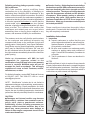
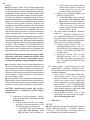
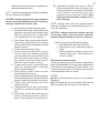
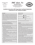
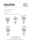
1
Instruction Sheet
No. 31-0000M
S&S Cycle, Inc.
Revised 6-29-99
14025 County Hwy. G
Box 215
Viola, Wisconsin 54664
Copyright ©
1995, 1996, 1998, 1999
by S&S Cycle, Inc.
All rights reserved
Printed in the U.S.A.
®
Phone 608-627-1497
Fax 608-627-1488
Customer Service email: [email protected]
Technical Dept. email: [email protected]
Website: www.sscycle.com
Installation Instructions for S&S
Super Stock and Special Application Big Twin Crankcases
Safe Installation and Operation Rules:
Before installing your new S&S crankcases, it is your
responsibility to read and follow the installation procedures in these
instructions and follow the basic rules below for your personal
safety.
● Read instructions thoroughly and carefully so all procedures
are completely understood before performing any installation steps.
Contact S&S with any questions you may have if any steps are
unclear or any abnormalities occur during installation or operation
of motorcycle.
● Consult an appropriate authorized H-D service manual for
correct disassembly and reassembly procedures for any parts other
than those outlined in these instructions.
● Use good judgement when performing installation and
operating motorcycle. Good judgement begins with a clear head.
Don't let alcohol, drugs or fatigue impair your judgement. Start
installation when you are fresh.
● Be sure all federal, state and local laws are obeyed with the
installation.
● Gasoline is extremely flammable and explosive under certain
conditions and toxic when breathed. Do not smoke. Perform
installation in a well ventilated area away from open flames
or sparks.
● If compressed air is used during installation, be particularly
careful. Compressed air and particles dislodged by compressed
air are harmful to eyes and body. Wear protective goggles, and
always direct air stream away from body parts such as hands and
eyes. Never direct compressed air toward other people.
● When using solvents, degreasers and other chemicals during
cleaning and installation, read manufacturer's instruction label for
proper use. Exposure of some chemicals to skin, eyes and/or
other body parts may be harmful. Many items are flammable and
present a fire hazard. Use in well ventilated area and wear
protective clothing when using them to avoid personal injury.
● If motorcycle has been running, wait until engine and exhaust
pipes have cooled down to avoid getting burned before performing
any installation steps.
● Before performing any installation steps disconnect battery to
eliminate potential sparks while working on electrical components.
● Be sure all fuel lines, supply and overflow, are routed correctly
and fuel line clamps are in place and tightened. Lines must not
contact exhaust pipes or other extremely hot surfaces where they
could melt or leak and catch fire.
● Before starting engine and riding motorcycle, be sure throttle
opens and closes smoothly. Turn handlebars to left and test throttle.
Then, turn bars to right and test throttle. To avoid possible loss of
control of motorcycle and potential personal injury to yourself or
others due to throttle sticking in open position, throttle must work
smoothly and return to a fully closed position when hand is removed
from throttle grip.
● Motorcycle exhaust fumes are toxic and poisonous and must
not be breathed. Run motorcycle in a well ventilated area where
fumes can dissipate.
IMPORTANT NOTICE:
Statements in this instruction sheet preceded by the following words
are of special significance:
WARNING
Means there is the possibility of injury to yourself or others.
CAUTION
Means there is the possibility of damage to the engine or
motorcycle.
NOTE
Other information of particular importance has been placed in
italic type.
S&S recommends you take special notice of these items.
WARRANTY:
All S&S parts are guaranteed to the original purchaser to be
free of manufacturing defects in materials and workmanship for a
period of six (6) months from the date of purchase. Merchandise
that fails to conform to these conditions will be repaired or replaced
at S&S’s option if the parts are returned to us by the purchaser
within the 6 month warranty period or within 10 days thereafter.
In the event warranty service is required, the original purchaser
must call or write S&S immediately with the problem. Some
problems can be rectified by a telephone call and need no further
course of action.
A part that is suspect of being defective must not be replaced by
a Dealer without prior authorization from S&S. If it is deemed
necessary for S&S to make an evaluation to determine whether
the part was defective, a return authorization number must be
obtained from S&S. The parts must be packaged properly so as
to not cause further damage and be returned prepaid to S&S with
a copy of the original invoice of purchase and a detailed letter
outlining the nature of the problem, how the part was used and
the circumstances at the time of failure. If after an evaluation has
been made by S&S and the part was found to be defective, repair,
replacement or refund will be granted.
ADDITIONAL WARRANTY PROVISIONS:
(1) S&S shall have no obligation in the event an S&S part is
modified by any other person or organization.
(2) S&S shall have no obligation if an S&S part becomes defective
in whole or in part as a result of improper installation, improper
maintenance, improper use, abnormal operation, or any other
misuse or mistreatment of the S&S part.
(3) S&S shall not be liable for any consequential or incidental
damages resulting from the failure of an S&S part, the breach of
any warranties,the failure to deliver, delay in delivery, delivery in
non-conforming condition, or for any other breach of contract or
duty between S&S and a customer.
(4) S&S parts are designed exclusively for use in Harley-Davidson
motorcycles. S&S shall have no warranty or liability obligation if
an S&S part is used in any other application.
2
Introduction
Installation of S&S Super Stock Big Twin crankcases is comparatively easy and can be performed by any Harley-Davidson repair shop
equipped to do complete engine overhauls. No special tools other than those used in normal engine building operations are required.
S&S Special Application Big Twin crankcases can be ordered for heavy duty street or race applications. Special Application
crankcases ordered for street engines are very similar to Super Stock cases and will be supplied with the same type of
hardware. Special Application crankcases for racing engines are a special order part and are machined to customer
specifications, so hardware and installation requirements may vary. If Special Application cases are ordered without an
alternator cut out for racing, the alternator cut out cannot be machined afterward. All S&S Special Application crankcases
must be used with a special S&S Big Twin pinion shaft #33-2040 which is .250" longer than stock.
NOTE - S&S crankcases are sold in matched sets only. Individual case halves are not available.
Kit Contents:
●
One set of S&S Super Stock crankcases with
following parts installed (see picture x):
– Left and right main bearing races (right race is final
honed and size is marked on tag wired to cases).
– 1 #31-4008 bushing, oil pump drive shaft (bushing is
reamed).
– 1 #31-4009 bearing assem., cam needle.
– 8 studs, cylinder (studs installed are appropriate part
for type of cases ordered).
– 1 #31-2006 plug, magnetic drain.
– 1 #31-2037 shaft, circuit breaker drive gear (’36 to ’69
cases).
– 1 #31-2039 shaft, idler gear (’36 to ’69 cases).
● One set of S&S Big Twin crankcase bolts (less two
bolts, washers and nuts used to hold cases together
for shipping).
● One #31-4013 bearing assem., left main (less races
installed by S&S).
● Assorted loose hardware and several hardware
packages in the following configurations:
– 1936 to 1947 Big Twins
1 #31-2005 plug, timing hole
1 #31-2017 spacer, motor mounting
1 #31-2021 fitting, oil line
1 #31-4010 seal, left main bearing oil - ’70-up BT
1 #31-4011 spacer, drive sprocket - ’70-up BT
1 #31-0000HC hardware pkg. - ’36-’64 BT
1 #31-0000HD hardware pkg. - ’36-’69 BT
– 1948 to 1964 Big Twins
1 #31-2021 fitting, oil line
1 #31-0000HA hardware pkg. - ’48-up BT
1 #31-0000HC hardware pkg. - ’36-’64 BT
1 #31-0000HD hardware pkg. - ’36-’69 BT
– 1965 to 1969 Big Twins
1 #31-2021 fitting, oil line
1 #31-0000HA hardware pkg. - ’48-up BT
1 #31-0000HD hardware pkg. - ’36-’69 BT
1 #31-0000HE hardware pkg. - ’65-’84 BT
– 1970 to 1984 Big Twins
1 #31-2021 fitting, oil line
1 #31-0000HA hardware pkg. - ’48-up BT
1 #31-0000HE hardware pkg. - ’65-’84 BT
1 #31-0000HF hardware pkg. - BT alt. left cases
– 1984 to present Big Twins
1 #31-0000HA hardware pkg. - ’48-up BT
1 #31-0000HB hardware pkg. - ’84-up BT
1 #31-0000HF hardware pkg. - BT alt. left cases
● Installation instructions.
●
●
Certificate of origin.
C.A.R.B. approved sticker (crankcases #31-0000,
#31-0003, #31-0005, and #31-0012) See Step #8.
Hardware packages listed above include the following parts:
● 31-0000HA - ’48-up BT
– 1 #31-2005 plug, timing hole
– 1 #31-2010 screen, crankcase oil
– 1 #31-2011 spring, crankcase oil screen
– 1 #31-4010 seal, left main bearing oil - ’70-up BT
– 1 #50-8008 o-ring
– 1 #31-6021 screw, cover
● 31-0000HB - ’84-up BT
– 1 #50-8112 fitting, 45° hose 1
⁄8" male pipe x 1⁄8" female pipe
– 1 #31-2016 switch assem., oil pressure
– 1 #31-4011 spacer, drive sprocket - ’70-up BT
– 1 #50-8113 fitting, 45° hose 1
⁄4" male pipe x 3⁄8" male hose
– 1 #50-8330 plug, SH pipe - 1⁄4-18
– 2 #50-8331 plug, SH pipe - 1⁄8-27
– 1 #50-8115 fitting, hose
● 31-0000HC - ’36-’64 BT
– 2 #50-7019 washer, lock - 1⁄4"
– 1 #31-2018 fitting, oil line
– 1 #31-4014 spacer, drive sprocket - ’36-'64 BT
– 1 #50-8331 plug, SH pipe - 1⁄8-27
– 2 #50-0015 screw, sltd RH - 1⁄4-20 x 1⁄2"
● 31-0000HD - ’36-’69 BT
– 2 #50-7019 washer, lock - 1⁄4"
– 1 #50-8331 plug, SH pipe - 1⁄8-27
– 1 #50-0069 screw, SHS - 1⁄4-20 x 1⁄4"
– 2 #50-0014 screw, HHC - 1⁄4-20 x 1⁄2"
– 1 #50-0018 screw, HHC - 1⁄4-20 x 1"
● 31-0000HE - ’65-’84 BT
– 1 #31-2019 fitting, primary oil return
– 1 #31-2020 fitting, rear chain/ “T” oil
– 1 #31-4011 spacer, drive sprocket - ’70-up BT
– 1 #50-8113 fitting, 45° hose 1
⁄4" male pipe x 3⁄8" male hose
– 1 #50-8115 fitting, hose
● 31-0000HF - BT alt. left crankcase
– 4 #50-0044 screw, SHC - 10-24 x 1"
– 1 #50-0045 screw, SHS - 10-24 x 5⁄16"
PRESENT S&S CRANKCASES AND
FLYWHEELS ARE NOT COMPATIBLE WITH
HARLEY-DAVIDSON ELECTRONIC FUEL
INJECTION (EFI) MODELS.
3
Polishing, painting, plating or powder coating
S&S crankcases
S&S Cycle cautions against modifying these
crankcases due to the possibility of damaging or
weakening them. Modifying S&S crankcases in any
fashion voids all manufacturer warranties. Should the
customer elect to modify the crankcases regardless, it
is imperative that they and the information tag attached
to them be inspected beforehand to confirm that the
correct model, style, year group, bore size, flywheel
diameter, oil pump mounting bolt hole pattern, etc. have
been provided. The customer must confirm that
crankcases and related parts are correct before
assembling them or having them modified in any
manner, and assumes all liability for modifications.
The customer must also verify that the serial numbers
on the crankcase and attached information tag
correspond with those on the certificate of origin and
packing carton. Note that all 4” bore Super Sidewinder
Long Blocks require Special Application crankcases,
which may be identified by the letters “SA” cast into
the left crankcase below the serial numbers and into
the right crankcase immediately ahead of the front lifter
guide opening.
Under no circumstance will S&S be held
responsible for expenses related to the
modification of any S&S part in the event warranty
service is required. Modified parts will not be
accepted for credit or exchange. This will apply
regardless of cause or fault: customer, retailer,
manufacturer, or other.
● Powder Coating - Subjecting heat-treated alloys
such as those used in S&S crankcases to excessive
heat can drastically alter their strength and their
critical properties. The degree of change depends
upon the temperatures reached and the duration
of exposure. When powder coating or otherwise
processing alloy parts, S&S exposes them to a
maximum temperature of 370°F for no longer than
20 minutes. Under no circumstances should parts
be heated past 400°F!
Please read these instructions thoroughly before
starting work. Proceed with the installation only after
they are completely understood.
Installation Instructions
1. Inspection
A. Inspect crankcases to confirm that they are
correct style and machined for correct bore size,
flywheel diameter, oil pump pattern, etc. Refer
to tag wired to crankcases.
B. Be sure serial numbers on crankcases match
numbers on packing carton and certificate of
origin. Contact S&S immediately if numbers do
not match.
C. Trial-fit crankcases in frame as described in
Section 9.
NOTES
● Valid certificate of origin is required for any transfer
or sale of aftermarket crankcases or complete engines
built with aftermarket crankcases. Certificate of origin
is required to title and license any motorcycle which is
to be driven on public streets and highways.
For further information, contact S&S Technical Services
at 608-627-1497, FAX 608-627-1488 or e-mail
[email protected]
NOTE - “Modification” includes but is not limited to
appearance changes such as painting, powdercoating,
plating, and polishing. Proper preparation for these
procedures as well as the processes themselves may
require the use of polishing compounds, chemicals or
procedures that are potentially harmful to crankcases.
CAUTION
● Passages and internal cavities may become
obstructed by residues from materials used to
polish, paint, plate or powdercoat surfaces.
Additionally, surface finishing processes can
damage critical machined surfaces. Any of the
above may cause premature wear, damage or
failure of other engine components as well as the
crankcases themselves.
Remove material in area indicated by shading.
Picture 1
4
● S&S crankcases manufactured before Fall, 1998,
require modification for use with 45 amp HarleyDavidson alternator supplied on ‘97-up fuel injected Big
Twins and available as upgrade kit H-D# 29999-97.
See Section 2, Final Preparation, for modification
procedure. Performed correctly, 45 amp alternator
modification will not void S&S warranty.
CAUTION - Failure to use spacer #31-4033 with 45
amp alternator will cause rotor to bottom against
crankcase when sprocket nut is tightened, causing
damage to crankcase, rotor, or both.
WARNING - To insure safe operation of motorcycle,
these operations must be performed correctly and
in a professional manner.
2. Final Preparation
A. If applicable, modify cases for 45 amp
alternator. This step is not required for all
models; see preceding note.
1. Carefully enlarge wiring recess in sprocket
side crankcase with mill or hand grinder and
remove all metal chips generated during
procedure. See Picture 1.
3. After completing engine assembly and installing
engine in frame, check primary chain run-out
according to procedure in H-D Service Manual.
Maximum permissible run-out is .030”. Prior to
operation of motorcycle confirm that primary
chain and drive assembly rotate freely and
without contacting alternator wiring harness,
crankcase, or other components.
NOTE - This step is not necessary in S&S crankcases
manufactured with large wiring recess.
WARNING - Incorrect installation of engine or
driveline could cause loss of control of motorcycle
with serious consequences to operator and other.
CAUTION - Do not increase depth of recess. Remove
minimum amount of material that will allow alternator
stator to mount on crankcase without crimping wiring
harness. Removing excess material may weaken
crankcase.
2. After installation of flywheel assembly,
S&S drive sprocket spacer #31-4011 and
Timken main bearing seal, place S&S
spacer #31-4033 (not provided) on
sprocket shaft between spacer #31-4011
and alternator rotor. See Picture 2.
Dimensions of spacer #31-4033 are 1.13”
(i.d.) x 1.73” (o.d.) x .325” (thickness).
B. Clean crankcases in hot soapy water or solvent
to remove any dirt or contamination which may
have been introduced during shipping, handling,
or set-up. If 1973-1980 stock Shovelhead oil
pump is to be used, refer to note in section 3-f,
Oil Supply Passages, prior to final preparation.
C. Carefully clear all oil passages with
compressed air.
WARNING - Compressed air and particles
dislodged by compressed air are potentially
harmful. Wear protective goggles when using
compressed air and always direct air stream away
from yourself and others nearby.
3. Hardware Identification and Installation
Picture 2
NOTES
● Some hardware supplied in crankcase kits may not
be needed.
● When installing hardware, be careful not to crossthread fittings or damage threads. Damage caused by
improper installation of hardware will not be covered
under warranty.
● To prevent galling, apply anti-seize compound or
Teflon tape to threads of all steel fittings prior to
installation in crankcase.
● If Teflon tape is used, loose tape must not enter
crankcase or oil passages. Do not apply tape to first 23 threads that screw into hole. If fittings are removed
or replaced be sure no tape shreds remain in holes.
Tape shred could block oil passages causing restriction
of oil flow.
5
A
A
C
B
C
G
E
E
F
Picture 3
Picture 4
CAUTION - Restricted oil flow may result in
extensive engine damage not covered under
warranty.
A. Gear cavity vent passage
Location: Hole A. See Pictures 3, 4, 5 & 6.
Hardware: #50-8115 hose fitting or #31-2018
oil line fitting. See Line Drawings on last
page, items #38 and 44.
Function: Vents gear cavity. Equalizes pressure
in gear case and oil tank. Is also connected
to primary chain case in 1965 - 1984 models
with dry clutch and engine-supplied primary
chain oiling.
Installation: 1936 - 1969
1. Install fitting #31-2018 in hole A.
2. Connect oil vent line from oil tank to fitting.
3. Install t-fitting H-D part #63580-66A if stock
1965-1969 primary chaincase oiling system
with dry clutch is desired. See Picture 7.
Installation: 1970 - present
1. Install fitting #50-8115 in hole A.
2. Connect oil line vent from oil tank to fitting.
3. Install t-fitting H-D part #63580-66A if stock
‘65-early ’84 dry clutch and engine-supplied
primary chaincase oiling system are desired.
See Picture 7.
C
C
B
A
B
A
G
G
E
D
D
E
H
Picture 5
F
Picture 6
F
6
Picture 7
B. Crankcase oil screen assembly
Location: Hole B. See Pictures 4, 5 & 6.
Hardware: #31-2010 crankcase oil screen, #31-2011
spring, #50-8008 o-ring, and #31-6021 cover
screw. See Line Drawings, items #15, 16,
17, 18.
Function: Prevents oil-borne contaminants
from reaching tappets and cylinder heads
in 1948 and later engines.
Installation: All engines 1948 and later.
1. Slip spring over screen and insert in hole B
with open end facing down See Picture 8.
2. Install cover screw with o-ring in place and
tighten with large screwdriver.
NOTE - If screen is removed, be sure to reinstall with
open end down and spring placed over screen as in
Picture 8.
C. Cylinder head oil supply passage/oil pressure
switch hole.
Location: Hole C. See Pictures 3, 4, 5 & 6.
Hardware: #31-2021 oil line fitting, #50-8112 45°
fitting, #31-2016 oil pressure switch assembly,
or #50-8331 socket head pipe plug. See Line
Drawing, items #28, 29, 32, 33.
Function: Supplies oil to cylinder heads in all
Shovelhead engines 1970 to 1984.
Alternative source of oil supply to heads for
Knuckles and 1963 to 1965. Panheads.
Accepts oil pressure switch in V2 engines
1984 to present.
Installation: 1970 to 1984 Shovelheads,
1936 - 1947 Knuckles and 1963 - 1965
Panheads with outside oiler heads.
1. Install fitting #31-2021 in hole C.
Picture 8
2. Connect oil line to crankcase fitting and to
rocker boxes on Knuckleheads, to cylinder
heads on 1963 to 1965 outside oiler
Panheads, or to rocker box on
Shovelheads.
Installation: 1984 - present V2 equipped with oil
pressure warning light only.
Install oil pressure switch #31-2016 in hole C.
Installation: 1984 - present V2 equipped with oil
pressure gauge.
1. Install 45° ⁄ " x ⁄ " pipe fitting #50-8112 in hole C.
2. Install oil pressure sending unit (HD
#74406-87) into #50-8112 fitting.
3. Position oil pressure sending unit to obtain
clearance by tilting it away from rear tappet
guide. See Picture 9.
1
8
1
8
NOTE- Install ⁄ ” pipe plug S&S part #50-8331 in hole C if
oil pressure switch or pressure gauge is not used.
1
8
Picture 9
7
D. Primary housing oil scavenge passage
Location: Hole D. See Pictures 5 & 6.
1965 - early 1984 engines with dry clutch
and engine-supplied primary chain oiling.
Hardware: #31-2019 primary oil return fitting
and #50-8331 socket head pipe plug. See
Line Drawing, items #33 & 34.
Function: Hole D leads to vacuum side of
crankcase breather gear. Hole D is normally
used to scavenge oil from primary chain
case in 1965 - early 1984 models with dry
clutch and engine-supplied primary oiling.
Installation: 1965 - early 1984 engines with dry
clutch and engine-supplied primary chain
oiling only.
1. Install fitting #31-2019 in hole D.
2. Connect fitting #31-2019 to oil scavenge
fitting on bottom of primary chain case with
⁄ " hose.
Installation: 1980 to present engines with primary
belt drive or sealed primary and wet clutch.
Install #50-8331 ⁄ -27 pipe plug in hole D.
3
8
1
8
NOTES
● Plug Hole D with #50-8331 ⁄ -27 pipe plug if primary
belt drive is used.
● Hole D and fitting #31-2019 may be used to return
top end oil in engines equipped with external oil
return lines. Connect oil return lines from front and
rear cylinder heads with “T” fitting. Install fitting S&S
#31-2019 in hole D and route remaining line from
“T” to this fitting. Breather gear will draw oil from
heads into gear case where oil pump can return it
to oil tank.
1
b. Connect ⁄ " ID. hose to #50-8113
fitting. Route ⁄ " hose down toward
ground or to rear chain. Avoid brake
and tire surfaces because oil-air mist
exits hose. Hose may also be routed
to carburetor air cleaner if desired or
required by local emission standards.
c. Connect rear chain oiler line to rear
chain oiler fitting on stock oil pump or
S&S oil pump. Avoid brake and tire
surfaces because oil-air mist exits hose.
3
8
3
8
WARNING - Oil on tires or brakes may cause loss
of control of motorcycle resulting in serious injury
to operator and others.
2. If room allows, breather t-fitting #31-2020
(See Line Drawing, item #37) may be
installed in hole E. Follow directions below
for 1970 to 1979 models.
NOTE - Installation of #31-2020 fitting may not be
possible on chassis with mechanical rear brakes due
to clearance problems.
8
E. Crankcase vent (breather) passage
Location: Hole E. See Pictures 3, 4, 5 & 6.
Hardware: #31-2020 rear chain/ “T” oil fitting,
#50-8113 45° hose fitting, or #50-8331
socket head pipe plugs. See Line Drawing,
items #35, 36, 37.
Function: Vents crankcase to atmospheric
pressure. Also used to oil rear drive chain
in some models.
Installation: 1936 to 1964 models with
crankcase breather stud.
Plug hole E with #50-8331 ⁄ -27 socket head
pipe plug. Do not overtighten.
Installation: 1965 to 1969 models
1. If separate breather and rear chain oiler
are to be used:
a. Install #50-8113 45° ⁄ " pipe x ⁄ " hose
fitting (See Line Drawing, item #35)
in hole E.
1
Installation: 1970 to 1979 models with rear chain
oiler.
1. Install fitting #31-2020 in hole E.
2. Connect ⁄ " ID. hose from rear chain oiler
fitting on oil pump to small “T” hose nipple
on #31-2020 fitting. See Picture 10.
3. Connect ⁄ " ID. hose to large hose nipple
on 31-2020 fitting. Route ⁄ " hose to rear
drive chain.
Installation: 1980 and later models with
crankcase breather vented to carburetor air
cleaner.
1. Install #50-8113 45° ⁄ " pipe x ⁄ " hose fitting
(See Line Drawing, item #35) in hole E.
3
3
16
8
3
1
8
1
4
3
8
Picture 10
4
8
3
8
8
2. Connect 3/8" hose to #50-8113 fitting and
route in stock-like manner to breather
fitting on rear of air cleaner backplate.
Installation: 1993 and later style engines with
crankcase pressure vented through cylinder
heads. Install #50-8330 ⁄ -18 pipe plug in
hole E.
1
4
NOTE - Although all S&S crankcases are machined
for crankcase breather vent, some late chassis lack
sufficient room between crankcase and transmission/
oil tank for correct breather fittings. S&S discourages
use of crankcase vent without correct fitting due to
possibility of oil reaching rear brakes or tire or abrasive
contaminants entering crankcase. In these instances,
crankcase pressure must be vented through cylinder
heads as on ‘93-up V2’s. With cylinder head venting,
hole E must be plugged for reasons mentioned above.
Additionally, leaving hole E open with ‘93-up OEM style
gear cover will cause large oil losses.
F. Oil supply passages
Location: Holes F & G. See Pictures 4, 5 & 6.
Hardware: #50-0024 socket head set screw.
See Line Drawing, item #51.
Installation: See Section 7F, Oil Pump, and
important note immediately following
Section 7F.
procedure prior to assembling crankcases and carefully
remove all metal chips generated during procedure.
G. Timing mark access hole
All models
Location: Hole A. See Picture 13.
Hardware: #31-2005 timing hole plug. See Line
Drawing, item #26.
Function: Hole serves as access to view timing
marks on left flywheel when setting ignition
timing.
Installation:
1. Thread plug in hole until it bottoms out
against case surface.
2. Tighten plug after ignition timing has
been static timed and before starting
engine.
H. Assorted screws, washers, etc. See Line
Drawing, items #40, 41, 48, 49, 50.
All models
Location and function:
#50-0014 ⁄ -20 x ⁄ " and #50-0018 ⁄ -20 x 1"
hex head cap screws and #50-7019 ⁄ " lock
washers are used to clamp timer assembly
down in ’36 to ’69 engines - ⁄ " screws are for
early timers and 1" screw is for later style
timers that require separate clamp. #50-0015
⁄ -20 x ⁄ " slotted round head screws and
#50-7019 ⁄ " lock washers are used to clamp
manual timer advance bracket to bracket
boss on ’36-’64 engines. See Picture 14.
#50-0044 10-24 x 1" socket head cap
screws and #50-0045 10-24 x ⁄ " socket
head set screw are used to mount alternator
stator and clamp wires on cases using
alternator left case half.
1
Note difference between S&S pump on left and '73-'80 OEM
pump on right.
Picture 11
1
1
2
4
1
1
1
NOTE - Installing stock 1973-1980 Shovelhead oil
pump on S&S alternator style crankcase will expose
oil passage immediately above crankcase hole for top
outside oil pump mounting bolt, resulting in large oil
leak. See Picture 11. Using S&S oil pump is
recommended. Otherwise, passage indicated (See
Picture 12) must be carefully tapped for 8-32 set screw,
and set screw installed with green Loctite. Perform
4
4
1
2
2
1
2
5
Picture 12
16
4
9
Picture 13
Picture 14
4. Magnetic drain plug
A. Place crankcases in frame to determine if
magnetic drain plug #31-2006, located on
bottom of cases, will be accessible. If drain plug
is obstructed by skid plate, hole must be drilled
in skid plate to provide access.
B. Place large amount of clay or putty on skid plate
in general area of drain plug. Drain plug will
make impression when cases are placed in
frame over clay.
C. Remove cases and drill hole in skid plate in
location indicated by impression in clay. Hole
must be large enough to accommodate
removal tool and drain plug.
5. Cylinder studs
Unless otherwise requested, S&S installs
appropriate cylinder studs in all S&S crankcases
prior to shipment.
NOTE - When servicing engine, do not overtighten drain
plug. Leave at least ⁄ " of plug above surface of
crankcase. See Picture 15.
NOTE - S&S can provide extra long cylinder studs, part
#31-2320, for these applications.
1
16
A. Crankcases made for Knuckle, Pan, or Shovel
type cylinders - Cylinder studs are installed to
1.330" for use with S&S Sidewinder big bore
cylinders as well as stock H-D style cylinders. If
cylinder base plate is used to increase cylinder
height, stud must protrude through gaskets, plate
and flange of cylinder far enough to allow full thread
engagement of base nut. Top of stud must be at
least flush with top of conventional base nut.
CAUTION - Overtightening drain plug may cause
plug to contact flywheels resulting in damage to
flywheels and other engine parts.
NOTE - Check magnetic drain plug for metal particles at
500 mile oil change. Break-in of new engine invariably
produces fine metal particles. Small accumulation of fine
material on magnetic drain plug is normal, and simply
shows that drain plug is doing its job. Significant amounts
of coarse metal particles or shavings indicate serious
engine damage and/or contamination during engine
assembly. In this event, engine should be closely
inspected before further operation.
CAUTION - Metal filings, dirt and other
contamination in engine oil may cause premature
wear and/or irreversible damage to bearings and
other engine components.
Arrow indicates difference that requires hole
illustrated in picture 12 to be plugged if '73-'80 OEM
pump used on S&S crankcases.
Picture 15
10
B. Crankcases made for V 2 type cylinders Cylinder studs are installed to stock H-D height
which is compatible with stock cylinders or any
S&S V2 Sidewinder kit. S&S V2 Sidewinder kits
utilize different length head bolt and washer
combinations to compensate for different
cylinder heights. These are included in kits with
cylinders longer than stock. Builders using kits
with stock or shorter than stock cylinders may
shorten stock bolts or purchase bolts of correct
length from S&S. If cylinder stud height
requirement is different than stock and extra
long bolts will not work, engine builder must
install custom studs with at least .750" of stud
thread engagement in crankcase. S&S has
produced two styles of cylinder studs for Big
Twin V2 engines. Part #31-2321, replaces H-D
#16937-85C, (See Figure 1) and has a single
collar. When installed correctly collar contacts
crankcase cylinder base gasket surface. Part
#31-2323 (See Figure 2) has two collars, either
of which can be installed against crankcase
cylinder deck.
NOTES
● V2 style cylinder studs are easily damaged. Install
lengths of ⁄ " ID. rubber or plastic tubing over each stud
to prevent nicks and scratches until top end is assembled.
Do not use studs as handle to lift or position crankcases.
● Unlike early style stock cylinder studs which rely on
interference fit between threads of case and stud to
hold them in place, S&S studs have standard thread fit
and are secured by combination of thread tension and
thread locking compound. Late style stock studs, H-D
#16937-85C, have same design.
1
2
CAUTIONS
● Seemingly insignificant damage to studs may
cause stress risers which can lead to stud failure
and possible damage to engine components.
Figure 1
● Insufficient thread engagement between stud
and base nut or stud and engine crankcase may
result in thread failure and major engine damage.
WARNING - Thread failure due to insufficient thread
engagement could cause violent engine
disintegration under power, resulting in loss of
control of motorcycle with serious personal injury.
NOTE - Older S&S V2 style Sidewinder big bore cylinders
may not fit over late style cylinder studs correctly,
preventing cylinder from seating on crankcase. See
Figure 3. Interference may seem minor, but forcing
cylinders down over collar may cause distortion of
cylinder bore and accelerated wear. Stud holes in S&S
cylinders produced after 4-95 have been enlarged to
provide adequate clearance.
CAUTION - Forcing cylinder over stud collar will
cause distortion possibly resulting in out of round
cylinder bore. Stress created by forcing cylinder
over stud may also cause cracking of cylinder, castin iron cylinder liner and/or damage or failure of
other engine components.
WARNING - Failure of cylinders, pistons and/or
other engine components due to cracked cylinder
may result in personal injury and/or loss of control
of motorcycle.
C. To correct fit of early Sidewinder cylinder on late
stud, perform following steps. See Figure 4.
1. Place cylinder on table of drill press or milling
machine with base gasket surface up.
2. Tighten ⁄ " drill bit in chuck and center stud
hole of cylinder under drill bit.
3. Clamp cylinder securely in position.
4. Remove ⁄ " and install ⁄ " or ⁄ " drill bit in
chuck. Set drill press stop so drill bit will
enlarge stud hole .100" to .110" deep below
base gasket surface of cylinder.
31
64
31
33
64
Figure 2
64
17
32
11
Stud collar may
prevent cylinder
from contacting
crankcase.
Counterbore
cylinder stud
hole .100" deep.
Cylinder
Cylinder
Crankcase
Crankcase
Stud Collar
Stud Collar
Stud
Stud
Figure 4
Figure 3
5. Carefully counter bore hole approximately .100"
deep. Use fairly low rpm and slow feed rate to
avoid catching drill bit and damaging cylinder.
6. Repeat for remaining stud holes.
7. Thoroughly clean all chips and foreign material
from cylinder stud holes and oil passages.
7. General Assembly Information
NOTES
● All S&S crankcase oil pump, tappet guide and gear
cover mounting holes are ⁄ -20 thread. Correct
hardware is readily available from most local sources.
Early ⁄ -24 fasteners used in stock crankcase up to
1978 must not be used in S&S crankcase. Damage to
cases caused by improper bolts, screws, etc. is not
covered under warranty.
● To help prevent thread damage, S&S recommends
use of anti-seize compound on threads of any steel
bolt or fitting installed in aluminum.
● S&S recommends high temp resistant RTV premium
silicone, ThreeBond 1104 or Hylomar sealant to seal
crankcase halves, according to builder’s preference.
Use any sealant sparingly to prevent excess material
from entering crankcase and obstructing passages or
contaminating engine oil.
1
1
CAUTION - Metal filings, dirt and other
contamination in engine oil may cause extensive
engine damage not covered under warranty.
WARNING - Compressed air and particles
dislodged by compressed air are potentially
harmful. Wear protective goggles when using
compressed air and always direct air stream away
from yourself and others nearby.
6. Circuit Breaker Drive Gear and Idler Gear Shafts
S&S ships generator style crankcase kits with circuit
breaker drive gear and idler gear shafts pressed and
bolted in place. Installation is performed at S&S using
a special fixture to insure proper alignment with gear
cover. Care must be taken to avoid hitting these shafts
during handling and assembly. Prior to installation of
flywheel assembly in crankcases, it is recommended
that gear cover to be used be slipped over shafts and
dowel pins to check fit. (See Section 7-H, Gear
Cover). Cover must not be forced on. If resistance is
encountered, stop immediately and determine cause.
Properly fit gear cover should slide over shafts and
pins without difficulty.
CAUTION - Incorrect gear cover fit may cause
abnormal stress between gears, gear shafts, pinion
shaft and/or camshaft resulting in rapid wear and/
or failure of these components.
4
4
CAUTIONS
● Use of hardware with incorrect threads will
damage crankcases.
● Contaminants in engine oil may block oil
passages resulting in damage to critical engine
components.
A. Crankcase bolt torque specifications (See “S&S
Crankcase Stud Locations” diagram near line
drawing for positions).
1. Position A ( ⁄ "): 12 ft. lbs.
2. Positions B to H ( ⁄ "): 15-18 ft. lbs.
1
4
5
16
B. Other crankcase fastener torque specifications
1. Tappet guide fasteners: 8-10 ft-lbs.
2. Oil pump mounting bolts: 8-10 ft-lbs.
3. Gear cover screws: 8-10 ft-lbs.
12
S&S Pinion Shaft Main Bearing Fitting Charts
Chart 1
BT Bearing
Race Diameter
1.7511
to
1.7513
1.7509
to
1.7511
1.7507
to
1.7509
For 1987 and later style bearings.
Pinion Shaft Bearing Diameter
1.2498-1.2500
Red
S&S #31-4016
HD #24628-87
Blue
S&S #31-4018
HD #24643-87
White
S&S #31-4005
HD #24626-87
1.2500-1.2502
Blue
S&S #31-4018
HD #24643-87
White
S&S #31-4005
HD #24626-87
Green
S&S #31-4016
HD #24628-87
C. Pinion shaft main bearing fit - Generally, fitment
specifications are identical to stock but type of
service must be taken into consideration.
Bearings in street engines that will receive
adequate break-in may be fit on tight side of
range to provide longer engine life. Competition
engines that will receive little or no break-in
should have bearings fit on looser side of range
to avoid seizure. All styles of main bearings
used from 1958 to present may be used in S&S
cases. For simplicity’s sake, only 1987 and later
style bearing fitment will be covered in these
instructions. If 1958 to 1986 style bearings are
used, consult H-D service manual for correct
fitment procedure.
NOTES
● Refer to information tag on crankcases for final
honed size of pinion shaft main bearing race.
● S&S pinion shaft main bearing fitting charts #1 and
#2 use H-D bearing color codes.
● All measurements must be taken with parts at room
temperature, approximately 70° F.
● Whatever style bearing is chosen, care must be
taken to position entire roller surface to completely
contact main bearing race and be completely contained
within race.
CAUTION - Improperly supported main bearings
may result in abnormal wear, bearing failure and/
or damage to other internal engine components.
1987 and later style pinion main bearings
1. Fitment method A - Use chart #1.
a. Refer to information tag on crankcases
to determine final honed size of inside
diameter of pinion shaft main bearing
race.
b. Measure pinion shaft bearing surface
diameter.
Chart 2
Bearing Race Diameter
Minus Pinion Shaft
Bearing Diameter
.5005 to .5009
.5007 to .5011
.5005 to .5013
.5011 to .5015
Bearing Color Code
Green
White
Blue
Red
S&S #31-4016
HD #24628-87
S&S #31-4005
HD #24626-87
S&S #31-4018
HD #24643-87
S&S #31-4017
HD #24641-87
c. Cross reference pinion race inside
diameter with pinion shaft bearing
surface outside diameter to determine
correct color code.
EXAMPLE - Pinion shaft bearing surface
diameter measures 1.2499" and is between
1.2498 and 1.2500 in left “Pinion Shaft Bearing
Diameter” column. Pinion bearing race inside
diameter is 1.7510" and falls between 1.7509
and 1.7511 in middle “Bearing Race Diameter”
column. Correct bearing color code where two
columns intersect is “BLUE”. Selecting color
where columns intersect provides proper fit for
normal service. If looser fit is desired, select
bearing color directly to right of color indicated
from selection process. If color indicated from
selection process is located in right color
column, go to next row directly below and select
color in left color column.
2. Fitment method B - Use chart #2.
a. Refer to information tag on crankcases
to determine final honed size of inside
diameter of pinion shaft main bearing
race.
b. Measure pinion shaft bearing surface
diameter.
c. Subtract pinion shaft bearing surface
diameter from pinion bearing race inside
diameter.
d. Select range in left “Bearing Race
Diameter minus Pinion Shaft Bearing
Diameter” column where difference best
splits high and low parameters of range.
Corresponding color bearing set in right
“Bearing Color Code” column provides
proper fit for regular service.
13
EXAMPLE - Pinion bearing race inside diameter
is 1.7510". Pinion shaft bearing surface
diameter is 1.2499". 1.7510" minus 1.2499" is
.5011". Difference of .5011" splits “.5009 to
.5013” range in third row exactly. Corresponding
“BLUE” color code in right column should be
used. Notice that .5011" fits in several range
groups. Try to select group where difference
falls closest to middle of range. If you are not
sure, select color that corresponds with group
closer to top of chart. This will provide slightly
looser bearing fit and help prevent bearing
seizure. Selecting next color up on chart may
also be done if looser fit is desired for
competition applications.
D. Stroker flywheels and connecting rods
1. Flywheels - S&S crankcases feature
adequate flywheel crankpin nut to case
clearance for strokes up to and including 5".
Recommended clearance between flywheels
and scraper is .008" - .010". Stock diameter
flywheels are 8 ⁄ "; standard small diameter
flywheels 8 ⁄ ". S&S crankcases can be
ordered machined for either or specially
machined for as small as 8" diameter.
2. Connecting rods - S&S crankcases feature
adequate clearance for most brands of
heavy duty connecting rods.
1
1
2
4
NOTES
● It is important to confirm flywheel diameter is correct
for crankcases. Flywheels that are too large will not fit in
crankcases. Flywheels that are too small will leave too
large a gap between flywheels and oil scraper resulting
in poor oil scavenging and possible oil consumption
problems. If flywheel diameter is smaller than diameter
crankcases were machined for, scraper should be built
up to provide proper clearance at rim of flywheels.
● Clearances between crankpin nut - case and
connecting rods - case must be checked by engine
builder during assembly. Engine damage resulting from
improper clearances is not covered under warranty.
CAUTION - Abnormal contact between moving
engine components due to improper clearances
may cause premature wear, damage or failure of
these parts or other components.
E. Camshaft - 1948 and later
S&S cases have sufficient clearance for lift up
to .631" with 1.000” base circle camshaft. If cam
with greater lift is to be used, clearance between
rear cam lobe and pinion shaft bearing race
must be checked and adjusted if necessary. A
special pinion shaft bearing race, preclearanced for use with cams up to .798" lift
with a 1.000" base circle is available. It is
especially important to check Knucklehead style
cases since most cams available are
aftermarket grinds with varying specifications.
F. Breather gear timing - Breather gear window
in crankcase is machined to maximum
specifications and should require no further
machining. In addition, breather passage
between flywheel cavity and breather gear bore
is cast in a special “ported” shape designed to
optimize flow of crankcase vapors and oil mist.
G. Oil pump
1. Oil pump compatibility
a. 1936 to 1947 (Knucklehead) engines Original stock cast iron, early stock alloy
1968 to 1969, or S&S #31-6250 oil
pump may be used. Passages in
crankcase are machined to provide
stock-like oil circulation.
b. 1948 to 1969 (Panhead and
Shovelhead) engines - Original stock
cast iron, early stock alloy 1968 to 1969,
or S&S #31-6250 oil pump may be used.
Passages in crankcase are machined
to provide stock-like oil circulation.
However, if S&S #31-6250 pump is
used, builder has option to separate oil
supply as in 1973 and later style oiling
system. This permits tappets and heads
to receive unrestricted oil supply first
Lower end main and connecting rod
bearings get secondary oil at lower
pressure after top end is supplied.
c. 1970 to present (alternator style)
engines - Top end and lower end oil
supply passages are separated and
pressure relief passage is drilled as in
stock late 1981 and later engines. S&S
#31-6260 oil pump kit may be used in
this application as may SOME stock
alloy H-D Shovelhead pump. Most 1973
- 1980 stock pumps leave pressure relief
passage in crankcase uncovered,
resulting in large oil leak (See Picture
12). S&S recommends S&S oil pump
for these applications, although stock
1973 - 1980 pump can be used if
exposed passage is plugged according
to procedure in Section 2-A.
14
NOTES ● Oiling systems in stock 1973 and later engines have
two distinct differences from earlier engines. Oil supplies
to top end and bottom end are separated, and connecting
rod bearings receive constant oil supply through pinion
shaft rather than intermittent supply as in earlier engines.
Oil supply is separated so tappets/heads get oil first at
highest possible pressure. In applications where hydraulic
tappets are used, this system maintains high oil pressure
to tappets assuring proper operation. After top end
components are satisfied, pressure relief valve opens
allowing oil to flow to bottom end bearings and other
components. After bottom end is satisfied, relief valve
opens further allowing excess oil to flow to incoming oil
supply passage side of pump. Separate oil supply
delivered to bottom end allows change in delivery at pinion
shaft from intermittent to constant feed system, hence,
end oiling style pinion shaft. S&S recommends separating
oil supply in generator style cases when hydraulic tappets
are used. This is possible only if S&S #31-6250 style
replacement oil pump is used. If stock, cast iron or early
alloy pump is used, oil supply cannot be separated and
pinion shaft must not be converted to constant oil feed.
2. Top of screw should be flush with or
slightly below gasket surface, but
screw should not extend deep
enough to block oil passage G.
b. Engines using hydraulic tappets and
S&S oil pump #31-6250
1. Thread #50-0024 socket head set
screw (See Line Drawing, item
#51) into hole G until it bottoms out.
2. Depth should be between .540" and
.600" from gear cover gasket
surface. Location of screw should be
between holes F and H.
3. Oil pump mounting hardware - Mounting
holes are ⁄ -20 thread. Tighten to 8-10 ft.
lbs. Installation hardware is not furnished
due wide variety of possible applications.
S&S oil pump kits include mounting screws.
Screws are also available separately.
a. Cast iron pump - Use two ⁄ -20 x 1 ⁄ "
(S&S #50-0080) and four ⁄ -20 x 2 ⁄ "
(S&S #50-0019) hex head cap screws
and one ⁄ " lock washer (S&S #50-7019)
for each screw.
b. Alloy pump - Use two ⁄ -20 x 1 ⁄ " (S&S
#50-0080) and four ⁄ -20 x 2 ⁄ " (S&S
#50-0081) hex head cap screws and
one ⁄ " lock washer (S&S #50-7019) for
each screw.
1
1
1
1
CAUTION - Using stock cast iron oil pump or 19681969 alloy pump with constant feed pinion shaft
oiling system can result in abnormally low oil
pressure with possible engine damage as a result.
● If stock alloy pump is used, proper identification to
confirm it is correct type is imperative. Different year
alloy pumps have design changes that could interfere
with oil circulation if used with wrong style crankcases.
Some early stock alloy pumps will also cause pressure
relief passage in S&S crankcase to be uncovered,
resulting in large oil leak.
● Pump and other parts such as pinion shaft and pinion
shaft bushings, rocker shafts and rocker shaft bushings,
lifters and lifter guides must be serviceable and in good
condition to insure proper oil pressure and circulation.
4
1
2. Crankcase oil supply passages - 1948 to
1969 (generator style) crankcase only See
Pictures 4 & 5.
a. Engines using stock cast iron or early
stock alloy oil pump assembly or S&S
#31-6250 pump and solid tappets
1. Thread #50-0024 socket head set
screw (See Line Drawing, item
#51) into hole F until it bottoms out.
4
1
4
3
4
2
4
2
4
4
H. Tappet guides - Mounting holes in S&S
crankcase are ⁄ -20 thread. Tighten to 8-10 ft.
lbs. Mounting screws are not furnished, but are
available separately.
1. 1936 to 1978 - S&S cases accept most
stock tappet guides. Due to casting
variations, however, some early cast iron
guides may require minor grinding at
corners adjacent to cylinder spigot bore
decks. Use four ⁄ -20 x ⁄ " (S&S #50-0068)
12 pt. cap screws and four ⁄ " (S&S #33-5308)
screw adapter washers for each guide. See
Line Drawing, items #13 & 42.
2. 1979 to present - Use four ⁄ -20 x ⁄ " (S&S
#50-0068) 12 pt. cap screws for each guide.
See Line Drawing Item #13 .
1
4
1
7
4
8
1
CAUTION - Insufficient oil supply may result in
premature wear or damage to critical engine
components.
1
4
1
1
1
4
4
1
I.
4
7
8
Gear cover
NOTES
● S&S crankcases accept S&S and stock H-D gear
covers. Mounting holes are ⁄ - 20 thread. Tighten to
8-10 ft-lbs. in all applications. Mounting screws are
not furnished, but are available separately.
1
4
15
● Some aftermarket gear covers have incorrect
machining that may cause poor alignment of oil
passages, pinion shaft, cam and dowel locations.
Incorrect machining on some 1970 to present
aftermarket covers may also cause poor alignment
between oil passage in gear cover pinion shaft oil
supply passage in crankcase. (See Figure 5).
Additionally, S&S has found some covers to have
porosity between pinion shaft oil supply and crankcase
breather passages. Result is that high pressure oil
intended for top end is diverted to breather cavity or
bottom end, starving hydraulic tappets, rocker arms,
etc. as a result. Problem may be intensified by heat;
as engine temperature increases, oil thins and pressure
drops, flywheel cavity becomes flooded with oil,
scavenging mechanism becomes overwhelmed and
excessive oil is blown out crankcase breather. Engine
damage may also occur.
● If stock gear cover is used, it must be correct design
for year group. 1970 to 1972 style cover could interfere
with oil circulation if used with 1973 and later end
oiling pinion shaft. Venting crankcase pressure out hole
E (See Picture 6)requires 1973-1992 style gear cover.
Operating engine with hole E open and 1993-up style
gear cover will cause large oil losses out crankcase.
● 1973 - 1992 style gear cover must be used if
crankcase pressure is vented directly out crankcase
rather than through cylinder heads as in 1993-up style
Big Twins. S&S recommends venting out hole E in
crankcase AND cylinder heads if ‘92-earlier gear cover
and ‘93-up rocker arm covers are available. S&S
supplies all Long Blocks with correct gear cover for
dual vent arrangement. S&S rocker covers are
compatible with cylinder head venting if umbrella valves
are installed correctly (See S&S Rocker Cover
Instructions #00-3885). If only cylinder head venting is
used, ‘hole E in Picture 6 must be plugged.
CAUTIONS
● Gear cover misalignment with crankcase
alignment dowels, pinion shaft and/or camshaft
may cause abnormal stresses resulting in shaft
breakage and other engine damage not covered
under warranty.
● Incorrect oil passage machining in gear cover
may cause low oil pressure resulting in extensive
engine damage not covered under warranty.
1. Compatibility
a. 1936 to 1969 engines - Stock H-D or
S&S gear covers may be used with S&S
generator style crankcases. See notes
and cautions above.
b. 1970 to present - Use appropriate year
group, 1970 to 1972, 1973 to 1992 or
1993 to present, stock H-D or S&S gear
cover. Do not use 1970 to 1972 type with
1973 and later end oiling pinion shaft.
See notes and cautions above.
2. Gearcase mounting hardware
a. To use stock gear covers with chamfered
mounting holes, fasteners with identical
chamfers must be used. Some builders
have used S&S ⁄ -20 x ⁄ " (S&S #50-0072)
Phillips oval head screws usually used to
install S&S teardrop air cleaner covers. As
an alternative, S&S offers special ⁄ " screw
adapter washers, S&S #33-5308 (See Line
Drawing, item #42), that are used with
regular ⁄ -20 x 1" socket head cap screws
such as (S&S #50-0084) or ⁄ -20 x ⁄ " 12 pt.
cap screws (S&S #50-0068). Screw
thread engagement in cases must be at
least ⁄ ". To check, install screw and
washer, if used, in gear cover and
measure amount of screw that
protrudes past gear cover gasket
surface. Allow for gasket thickness.
b. Stock gear covers utilize several different
length screws with washers. Screws in
S&S cover kits are identical in length.
They are ⁄ -20 x 1 ⁄ " (S&S #50-0008).
Washers supplied are S&S #50-7020.
3. Installation
a. Thoroughly clean all parts.
1
3
4
4
1
1
4
1
1
4
4
7
8
2
1
4
1
4
1973-up Pinion
shaft oil feed hole
Pinion shaft oil feed
hole in cam cover
too large and located
too low. Overlaps
both feed holes in
cover gasket and
crankcase.
WARNING
● Attempting to use ‘93-up OEM style gear cover on
engine with direct crankcase venting will result in
large oil losses with possible loss of control of
motorcycle and serious injury to operator and others.
1970-72 Pinion
shaft oil feed hole
Figure 5
16
b. Prior to flywheel installation, slip gear
cover over alignment dowel pins in
crankcase. Cover must not be forced.
If resistance is encountered, determine
cause and correct. Remove cover.
c. After flywheels and cases have been
assembled but before pinion gear and
cam are installed, reinstall gear cover to
check fit over pinion shaft. Remove cover.
d. Install pinion gear and camshaft, and
repeat step 3. By fitting gear cover in
stages, it is easier to pinpoint source and
correct alignment problems.
J. Generator/Alternator
1. Generator right case equipped crankcases
- S&S generator style crankcases are
machined for late style generators that use
⁄ " mounting screws and 1.800" dia.
centering boss behind gear. Crankcases are
not designed for early generators with ⁄ "
screws and cradle/strap mounting
arrangement.
2. Alternator left case equipped crankcases Latest S&S alternator style crankcases are
machined to accept current production H-D
rotors and stators. S&S crankcases shipped
before late mid-Fall, 1998, may require
modification to accept H-D 45 amp alternator.
See note in Section 2-A.
3. Use of early plastic coated stators and rotors
with diameters greater than 6.470" is not
recommended due to insufficient clearance
between rear of stator and case and OD of
rotor and case. It is possible to clearance
cases for these parts, but S&S recommends
use of later parts due to increased reliability.
5
16
1
4
K. 1992 and later style oil filter - All S&S alternator/
cone style right crankcases feature 1992 and
later style oil filter mounting bosses located just
forward of gear cavity. When mounting oil filter
or other accessories, use ⁄ -18 thread screws of
correct length to provide ⁄ " minimum thread
engagement. To check, install screw and
washers, if used, in mounting flange/bracket and
measure amount of screw that protrudes past
mounting surface.
5
Air Resources Board, executive order #D-355-4,
as replacements for use on pollution controlled
vehicles in California. Supplied with each set of
approved crankcases is one-time use C.A.R.B.
approved sticker (See Figure 6). This sticker must
be applied to frame of motorcycle in visible location,
preferably near frame serial number.
Only crankcases with following S&S part numbers
are legal replacement for Pollution-controlled
vehicles:
#31-0000 - stock bore 1984-91 Big Twin.
#31-0003 - stock bore 1970-84 Big Twin.
#31-0005 - stock bore 1992-up Big Twins
(without fuel injection).
#31-0012 - 1984-91 style crankcases for 1984
and earlier frames.
To install sticker perform following steps:
1. Thoroughly clean and dry area to which
sticker will be applied.
2. Remove paper backing from sticker.
3. Carefully place sticker in desired position
and press sticker on frame of motorcycle.
4. Smooth any wrinkles or air bubbles by
gently pressing them outward from center
of sticker past edge.
9. Frame
S&S crankcase installation in frame/chassis is
essentially the same as stock, although additional
clearancing and shimming may occasionally be
required. Main areas of concern are between cases
and frame motor mounts and, in 1965 to 1969
engines, between cases and primary chain cover.
A. Crankcase to frame motor mount clearance Checking clearance around and between case
mounting bosses and frame is necessary to
ensure that crankcase rests squarely on motor
mount pad and no stress is applied to
crankcases when mounting bolts are tightened.
16
3
4
8. S&S Replacement Crankcases for Pollutioncontrolled vehicles in California.
S&S crankcase kits, parts #31-0000, 31-0003,
31-0005 and 31-0012, are approved by California
S&S Cycle Inc.
P/N 31-0000, 31-0003,
31-0005, 31-0015
CRANKCASE ASSEMBLY
C.A.R.B. # D-355-4
Figure 6
17
Shimming may be required to compensate for
variances between frames.
NOTE - Crankcases damaged by improper installation
are not covered under warranty.
CAUTION - Improper alignment of engine and frame
mounts may cause abnormal stresses resulting in
damage to crankcases or other parts.
To check clearance perform following steps:
1. Assemble case halves using several case
alignment studs and several regular case
bolts. Snug nuts and bolts. Torquing bolts
to final specification is not necessary.
2. Clean frame engine mounts and carefully
remove any irregularities from mounting
surfaces. Also inspect crankcase mounting
bosses for burrs.
3. Position case assembly in frame.
4. Install engine mounting bolts in motor
mounts, and check clearance between
mounting bosses on cases and frame and
any other areas where frame and cases
may contact each other. Bolts may be
difficult to install if contact is severe.
5. If cases contact frame, remove them and
relieve just enough material in offending
area to provide clearance.
6. Place cases in frame, install one rear
mounting bolt and snug nut.
7. Measure gap between crankcase mounting
bosses and frame motor mounts with feeler
gauge to determine if shimming is required.
8. If gap exists, fabricate shim just thick
enough to fill gap
9. Install opposite corner shim and mounting
bolt and nut, and tighten identical to other
bolt.
10. Check other corners with feeler gauge to
confirm thickness required is same as
before. If not, determine cause and correct.
B. Crankcase to primary chain cover on 1965 to
1969 models with cast aluminum primary - Due
to casting variations, contact may occasionally
occur between inner primary cover and
crankcase bolt at position D. See “S&S
Crankcase Stud Locations” diagram insert
in line drawing.
NOTE - Bolting cases and cover together without
adequate clearance may create abnormal stress on
cover and crankcase
CAUTION - Improper clearance between case bolt
and primary chain cover may cause abnormal
stress resulting in damage to cover or crankcases.
To check clearance perform following steps:
1. Bolt assembled case halves in frame.
2. Bolt primary cover to case with gasket in
place.
3. Check clearance between case bolt at
position D and cover. Grind clearance on
cover as needed.
Replacement crankcase parts
Use the line drawings to identify required replacement
parts. Parts designed to fit as direct stock replacements
are listed with corresponding H-D part number. If no
H-D part number is shown, S&S part cannot be used
in stock application and vice versa.
NOTES
● Right and left crankcase halves are not available
separately.
● Parts marked N/A are not available. Parts marked
N/S are available but not shown on line drawing.
18
S&S Super Stock and Special Application
Big Twin Crankcases
1. Crankcase half assembly ..................................................... N/A
2. Right main bearing race - ’58-up BT
Standard (HD #24599-58B) ........................................ #31-4004
+.002" O.S. (HD#24600-58B) ..................................... #31-4006
+.005" O.S. (HD#24601-58B) ..................................... #31-4007
Std. (clearanced .798” lift V2 cam w/1" base circle) ...... #31-4024
+.002" O.S. (clear’d .798" lift V2 cam w/1" base circle) . #31-4026
+.005" O.S. (clear’d .798" lift V2 cam w/1" base circle) .. #31-4027
3. Right main bearing assembly - ’87-up BT
White (HD#24626-87) ................................................ #31-4005
Green (HD#24628-87) .............................................. #31-4016
Red (HD#24641-87) .................................................. #31-4017
Blue (HD#24643-87) ................................................. #31-4018
4. Main bearing retaining ring - ’58-up BT (HD#11177A) . #31-4021
5. Cam needle bearing assem. - ’58-up BT (HD#9058) .. #31-4009
6. Cam lockwasher - ’58-up BT (HD#25550-57) ............. #33-5201
7. Cam thrust washer - ’36-up BT
.050" thick (HD#25550-36) ........................................ #33-5200
.055" thick (HD#25551-36) ........................................ #33-5202
.060" thick (HD#25552-36) ........................................ #33-5203
.065" thick (HD#25553-36) ........................................ #33-5204
.070" thick (HD#25554-36) ....................................... #33-5205
8. Left Timken® main bearing assembly
S&S ’36-up BT (HD#9028) Stock ’69-up ..................... #31-4013
S&S ’70-up SA BT w/11⁄2" dia. sprocket shaft ............... #31-4000
9. Drive sprocket spacer
S&S ’36-’64 BT ........................................................... #31-4014
S&S ’65-up BT repl. HD#24002-70 ............................. #31-4011
10. Sprocket shaft oil seal
S&S ’36-up BT (HD#12026A) .................................... #31-4010
S&S ’70-up SA BT w/ 11⁄2" dia. sprocket shaft .............. #31-4002
11. Oil pump shaft bushing - ’36-up BT (HD#24641-36) ... #31-4008
12. Tappet guide assembly - ’84-up BT
Includes 1 each tappet guide, gasket, & 4 screws
Front (HD#18542-83A) ........................................... #33-5301F
Rear (HD#18540-83A) ............................................ #33-5301R
Set ............................................................................ #33-5301
13. DHH 12 pt. screw - 1⁄4 -20 x 7⁄8" (HD#3770) .................. #50-0068
14. Tappet block gasket - ’48-up BT
Front (HD#18634-48C) ........................................... #33-5302F
Rear (HD#18633-48D) .......................................... #33-5302R
Set ............................................................................. #33-5302
15. Crankcase oil screen-S&S ’48-up BT (HD#24981-70) .. #31-2010
16. Crankcase oil screen spring
S&S ’48-up BT (HD#24982-70) ................................. #31-2011
17. Cover screw oring S&S ’48-up BT (HD#11105) ......... #50-8008
18. Cover screw - S&S ’48-up BT (HD#26263-80) ............ #31-6021
19. Cylinder stud
’36-’84 BT (HD#16837-78) ......................................... #31-2320
’36-’84 BT + 5⁄16 longer .................................................. #31-2320
’85-up BT (HD#16837-85B) ....................................... #31-2321
’86-up XL (HD#16832-86) .......................................... #31-2331
20. Hex head case bolt (see location diagram)
1
⁄4 -28 x 5 1⁄2" (position A ’36-up BT) .............................. #50-0090
5
⁄16-24 x 5" (HD#3430) (position C ’36-up BT) .............. #50-0119
5
⁄16 -18 x 33⁄4" (pos. H ’36-’69 BT, D ’65-’69 BT) ............. #50-0011
21. Case alignment stud
5
⁄16 -24 x 5 3⁄4" (HD#3506)
(position B ’36-up BT, E, F, G ’70-up BT) ..................... #31-2003
5
⁄16 -24 x 6 1⁄16" (pos. E, F, G ’36-’69 BT) ......................... #31-2034
22. Hex nut - 1⁄4 -28 repl. HD #7683 ........................... Part #50-5011
23. Flat washer - 1⁄4 x 5⁄8x 1⁄16 steel repl. HD#6245 ........ Part #50-7021
24. Hex nut - 5⁄16 -24 repl. HD#7833 ................................... #50-5023
25. Flat washer - 5⁄16 x 11⁄16 x 1⁄16 steel repl. HD#6702 ............ #50-7034
26. Timing hole plug - S&S ’36-up BT (H-D #720) ............ #31-2005
27. Drain plug ................................................................... #31-2006
28. 45° fitting 1⁄8 pipe x 1⁄8 pipe ............................................ #50-8112
29. Oil pressure switch (H-D #26561-84)
(incl. 1 ea. switch, nut, & lock washer) ........................ #31-2016
30. Lock washer #10 N/S repl. HD#7069 .......................... #50-7000
31. Hex nut - 10-32 x 3⁄8 N/S repl. HD#7634 ...................... #50-5000
32. Oil line fitting repl. HD#62484-81 ................................ #31-2021
33. Soc. hd. pipe plug - 1⁄8-27 ............................................ #50-8331
34. Oil return fitting repl. HD#63533-65 ............................. #31-2019
35. 45° fitting - 1⁄4 pipe x 3⁄8 hose ......................................... #50-8113
36. Soc. hd. pipe plug
1
⁄8 -27 (’36-’64) ............................................................. #50-8331
1
⁄4 -18 (’65-’69) ............................................................. #50-8330
37. “T” fitting repl. HD#63541-70 ...................................... #31-2020
38. Hose fitting repl. HD#63533-41 ................................... #50-8115
39. Dowel pin
.370" dia. x 3⁄4 (’36-’69) repl. HD#377 ........................... #50-8017
.250" dia. x 1⁄2 (’70-up) repl. HD#358 ............................ #50-8022
40. Soc. hd. cap screw - 10-24 x 1" (stator) N/S (HD#2720)
................................................................................... #50-0044
41. Soc. hd. set screw - 10-24 x 5⁄16 (stator plug clamp) N/S
................................................................................... #50-0045
42. Screw adapter washer ................................................ #33-5308
43. Crankcase breather stud
(position D ’36-’64 BT) (HD#24912-48) ...................... #31-2036
44. Oil line fitting (HD#63533-15) ..................................... #31-2018
45. Circuit breaker drive gear shaft
’36-’69 BT (HD#25856-36) ......................................... #31-2037
46. Soc. hd. cap screw
1
⁄4 -20 x 3 1⁄4 (circ. brkr. drive gear shaft) ........................ #50-0012
1
⁄4 -20 x 2 (idler gear shaft) .......................................... #50-0013
47. Idler gear shaft - ’36-’69 BT (HD#25791-36) .............. #31-2039
48. Lock washer - 1⁄4 (HD#7035) ....................................... #50-7019
49. Hex hd. cap screw
1
⁄4 -20 x 1/2 (’36-’65 timer) ............................................ #50-0014
1
⁄4 -20 x 1" (’66-’69 timer) ............................................. #50-0018
50. Sltd. rd. hd. screw - 1⁄4 -20 x 1⁄2 ..................................... #50-0015
51. Soc. hd. set screw - 1⁄4 -20 x 3⁄16 ................................... #50-0024
52. Gear cover kit (see gear cover section of catalog for details)
53. Gear cover gasket
’36-’69 BT (HD#25225-36C) ...................................... #31-2030
’70-up BT (HD#25225-70B, 25225-93) ...................... #31-2031
54. Pinion shaft assembly
Standard SA - ’81-’89 BT N/S ..................................... #33-2040
55. Internal retaining ring 11⁄2 diameter left Timken®
main bearing assembly N/S ........................................ #31-4001
19
S&S Super Stock
Alternator Crankcase Assembly
19
29
32
20
39
33
28
A
12
13
H
10
26
9
C
18
17
8
14
16
15
25
20
D
G
24
23
2
22
F
E
53
1
27
39
5
1
6
7
38
36
33
39
3
11
4
21
34
35
25
37
52
25
24
24
S&S Super Stock
Generator Crankcase Assembly
53
19
29
20
32
33
39
28
52
26
10
9
18
8
24
13
17
42
16
49
14
23
15
25
48
22
50
48
2
43
39
47
1
46
27
5
45
1
6
38
44
33
34
51
25
25
35
36
4
21
11
37
3
51
24
24
46
7
20