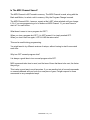
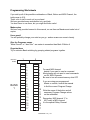
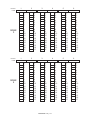
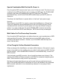
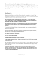
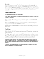
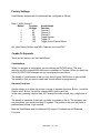
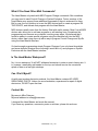
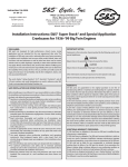
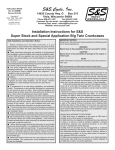
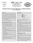
1
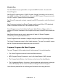
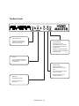
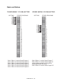
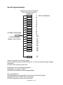
OWNERS MANUAL
Version 1.1
December, 2001
Headmaster 1.0 p 1
Introduction
The Head Master is a programmable, foot operated MIDI Controller. It contains 30
Stored Programs.
Each Stored Program contains 16 MIDI Program Change Commands, one for each of
the 16 MIDI channels. (The Head Master only sends MIDI Program Change commands,
not MIDI Control or System Exclusive commands)
Each Stored Program also contains a special non-MIDI Command to control the internal
relays.
Each Command contained in a Stored Program can be turned ON or OFF individually.
When a Command is turned ON, it is referred to as Active.
Stored Programs are activated by the 6 Program Select Buttons. When a button is
pressed, ALL Active Commands in the Program will be sent to the MIDI devices and the
relays.
Bank Select Buttons can be used to select one of 5 sets of 6 Stored Programs
controlled by the Program Select Buttons.
Stored Programs can be created or changed using the onboard Programming Buttons.
The Stored Programs are saved in Non-Volatile memory. The term "non-volatile" means
that the Programs are retained when the power is turned off.
Programs, Programs And More Programs
The word "Program" will be used quite a bit in this manual. It is used to describe:
•
The Stored Programs contained in the Head Master memory.
•
MIDI Program Change Commands - sent by the Head Master to MIDI devices.
•
The Program Select Buttons - the 6 buttons on the front of the Head Master.
•
The Programming Buttons - the array of seven membrane switch buttons to the right
of the LED display, that are used to create and change the Stored Programs.
I know this may seem a little bit confusing, but it's hard to avoid using that word.
Headmaster 1.0 p 2
The Top Panel
BANK SELECT BUTTONS
The Head Master contains 30 Stored Programs
The Bank Select Buttons are used to select
which set of 6 Stored Programs is controlled
by the 6 Program Select Buttons
When you press one of these buttons, the
Bank is changed but NO MIDI commands
are sent
LED DISPLAY
In Normal Mode, shows the
current Bank and last Button
PROGRAMMING BUTTONS
In Programming Mode, shows
the MIDI channel or
Program Change
Use these buttons to create
or change stored programs
PROGRAM SELECT BUTTONS
Press one of these buttons to
send a stored program to
the MIDI devices
A stored program can contain
up to 16 MIDI Program Change
commands and a special
Relay Command
Headmaster 1.0 p 3
The Back Panel
AUX POWER OUT
Supplies a limited amount
of DC power for other gear
such as stomp boxes
AUX POWER IN
Supplies power to the
Head Master when it is used
WITHOUT a Rivera Amp that
provides power
NEVER use the RIVERA AMP
POWER IN and AUX POWER IN
at the same time
RELAYS
Three single pole double throw
(SPDT) relays for controlling
non-MIDI amps
RIVERA AMP
Special combination
MIDI Output and DC Power
Input
Only works with Rivera Amps
that provide power
NEVER connect this to a
regular MIDI device
MIDI OUT
Standard MIDI Output
Use this to control any
MIDI device.
Headmaster 1.0 p 4
Banks And Buttons
When designing a foot-operated controller there is always the question:
How Many Buttons?
Fewer buttons make the unit smaller, lighter, easier to pack and easier to fit on a
crowded stage.
More buttons give the player a larger number of choices. But if the buttons must be
operated with a foot, they can't be placed too close together. This means that a footoperated controller with lots of buttons gets really big.
To achieve a compromise between size and flexibility, the Head Master is organized as
a set of 5 banks of 6 buttons each. This results in a unit having 30 available Stored
Programs, but only 8 buttons - 2 to select the Bank and the other 6 to select the
Program.
As shown on the next page, Bank Switching allows 6 buttons to control 30 Stored
Programs. Think of the Bank Selector as a control that tells the Buttons WHICH set of 6
Stored Programs to control.
Bank + And Bank –
The Bank Select Buttons are labeled Bank + and Bank -.
When you press Bank +, the bank is incremented by one.
If Bank 5 is selected, and Bank + is pressed, the Bank rolls over to 1.
When you press Bank -, the Bank is decremented.
If Bank 1 is selected, and Bank – is pressed, the Bank rolls over to 5.
NO MIDI COMMANDS ARE SENT when the Bank Select buttons are pressed.
The LED display shows the CURRENT Bank, and the LAST Button pressed.
Example:
If Bank 1 is selected, and Button 2 is pressed, the display shows
Bank 1 Button 2
If Bank + is then pressed, the display shows
Bank 2 Button 2
But, since no MIDI Commands have been sent, you are still playing the Program
Bank 1 Button 2
Headmaster 1.0 p 5
Banks and Buttons
WHEN BANK 1 IS SELECTED
BUTTONS
1
2
3
4
5
6
STORED PROGRAMS
WHEN BANK 2 IS SELECTED
BUTTONS
1
2
3
4
5
6
7
8
9
10
11
12
13
14
15
16
17
18
19
20
21
22
23
24
25
26
27
28
29
30
1
2
3
4
5
6
Bank 1 Button 1 controls Stored Program 1,
Bank 1 Button 2 controls Stored Program 2,
Bank 1 Button 3 controls Stored Program 3,
Bank 1 Button 4 controls Stored Program 4,
Bank 1 Button 5 controls Stored Program 5,
Bank 1 Button 6 controls Stored Program 6.
STORED PROGRAMS
1
2
3
4
5
6
7
8
9
10
11
12
13
14
15
16
17
18
19
20
21
22
23
24
25
26
27
28
29
30
Bank 2 Button 1 controls Stored Program 7,
Bank 2 Button 2 controls Stored Program 8,
and the pattern repeats for all remaining
Banks and Buttons until finally,
Bank 5 Button 6 controls Stored Program 30
Headmaster 1.0 p 6
Inside A Stored Program
MEMORY SLOTS CONTAINING
MIDI PROGRAM CHANGE
COMMANDS
1-128
1-128
1-128
1-128
1-128
1-128
1-128
1-128
STORED PROGRAM
1-128
1-128
1-128
1-128
1-128
1-128
1-128
1-128
1-128
1
2
3
4
5
6
7
8
9
10
11
12
13
14
15
16
17
MIDI CHANNELS
MIDI Channel 17 is NOT a real MIDI channel.
It is the special Relay Channel.
MIDI Channel 17 CANNOT be used
to control MIDI devices.
It can ONLY be used to control the relays.
A Stored Program is controlled by a Bank-Button pair
Each Stored Program contains 16 MIDI Program Change Commands,
one for each of the 16 MIDI Channels
It also contains a special, non-MIDI code to control the Relays
Each Bank-Button-MIDI Channel combination represents one slot in the memory
Each slot can be turned ON or OFF
Headmaster 1.0 p 7
Stored Program Example
MEMORY SLOTS CONTAINING
MIDI PROGRAM CHANGE
COMMANDS
16
1 MIDI CHANNELS
2
3
4
5
6
7
8
9
10
11
12
13
14
15
16
32
17
64
25
STORED PROGRAM
99
CONTROLED BY
BANK 3 BUTTON 4
Here is an example of a Stored Program
In this example, the slots for MIDI Channels 4, 5, 9 and 16 contain Program Change
commands
All other slots have been turned OFF
Imagine that you are currently using Bank 2
Press Bank + to change to Bank 3
(No MIDI Commands are sent by changing Bank)
Now, press Button 4
The Head Master will examine ALL of the slots of the Stored Program
Slots that have been turned OFF will be ignored
All MIDI Commands in active slots will be sent
Headmaster 1.0 p 8
So, Pressing Button 4 while in Bank 3 will command the Head Master to send:
Program Change 64 on MIDI Channel 4
Program Change 25 on MIDI Channel 5
Program Change 99 on MIDI Channel 9
Program Change 16 on MIDI Channel 16
AND
Special Relay Command 32 to the Relays
Programming The Head Master
During programming, the Bank, Button, MIDI Channel and Program Change values
must be displayed, and edited. Since we decided to make the unit small, there was not
room for individual displays for all of these values.
So, we have to share the display, by the use of Programming Modes.
The three modes are:
Normal Mode
The display shows the CURRENT Bank and LAST Button
MIDI Channel Mode
The display shows the MIDI Channel
Program Change Mode
The display shows the MIDI Program Change
It is always possible to know what mode the Head Master is in by looking at the display.
The illustration on the next page shows how the digits are grouped to make mode
identification easy.
Headmaster 1.0 p 9
Modes Diagram
It is always possible to determine
the mode by looking at the display
NORMAL MODE
The left digit is the Bank
The right digit is the Button
The center digit is blank
PROGRAMMING MODES
The programming modes are used to
examine, change or create stored programs
MIDI CHANNEL SELECT MODE
The left digit is blank
The right two digits show the MIDI Channel
Two digits are always used,
so MIDI Channel 1 is displayed as 01
PROGRAM CHANGE SELECT MODE
All three digits show the MIDI Program Change
Three digits are always used,
so Program Change 48 is displayed as 048
PROGRAM CHANGE SELECT MODE
If all of the digits are blank, the Program Change for
this combination of Bank-Button and MIDI Channel
has been turned OFF
Headmaster 1.0 p 10
The Programming Buttons
The 7 Programming Buttons are used to program the Head Master
Programming Buttons are associated with modes as follows:
MIDI CHANNEL +
MIDI CHANNEL –
Are used in MIDI Channel Mode
PROG CHANGE +
PROG CHANGE ON
OFF
SAVE
Are used in Program Change Mode
Each button actually performs two functions
Changing the Mode
Editing the Value
When a Programming Button is pressed, the Head Master first checks to see if it is in
the mode associated with the button.
If the Mode does NOT match the button, the mode is changed, but the value is not
If the mode matches the button, the value is changed.
To put it another way, the FIRST press changes the mode WITHOUT changing the
value. The SECOND and all following presses, change the value.
If you press a button and release it quickly, the value is changed by 1. If you hold down
a button for a few seconds, the value will change continuously. If the value gets to the
end of its range, it will roll over to the beginning.
Headmaster 1.0 p 11
Tutorial:
(For the purpose of this tutorial, assume that Program Change 97 has been stored in
the memory slot selected by Bank 1 Button 1 MIDI Channel 1)
Select Bank 1 and Press Button 1
The Head Master is in Normal Mode
The display reads 1 1
Press MIDI CHANNEL + or MIDI CHANNEL –
The Mode changes to MIDI Channel Mode
The display now reads 01
This indicated that MIDI Channel 1 is selected
Press MIDI CHANNEL +
Since the Head Master is already in MIDI Channel Mode
the mode does not need to be changed
The MIDI Channel value is changed to 2
The display now reads 02
Press PROG CHANGE + or PROG CHANGE The Mode changes to Program Change Mode
The display now reads 097
This indicates that the Program Change 97 is associated with
Bank 1, Button 1, MIDI Channel 1
Press PROG CHANGE +
Since the Head Master is already in Program Change Mode
the mode does not need to be changed
The Program Change value is changed to 98
It is NOT saved to the memory yet,
it is placed in a temporary editing area
The display now reads 098
Press OFF
Since the Head Master is already in Program Change Mode
the mode does not need to be changed
The Program Change is turned off
The temporary editing area is NOT erased
The display is now blank
Press ON
Since the Head Master is already in Program Change Mode
the mode does not need to be changed
The Program Change is turned back on
The display now reads 098
Headmaster 1.0 p 12
Switching modes like this can be confusing, sometimes you may forget where you were
I forgot which MIDI channel I was programming
Press MIDI CHANNEL + or MIDI CHANNEL –
The Mode changes to MIDI Channel Mode
The MIDI Channel is NOT changed
The display now reads 02
I forgot which BANK and Button I was programming
Press BANK + or BANK – or Buttons 1-6
The Mode changes to Normal
MIDI commands are NOT sent, the Bank or Button
is NOT changed, ONLY the Mode is changed
The display now reads 1 1
I forgot which Program Change I was programming
Press PROG CHANGE + or PROG CHANGE The Mode changes to Program Change Mode
The Program Change value is NOT changed
The display now reads 098
You now have two choices, SAVE or not
If you press SAVE
The Program Change is saved in the memory slot selected by the
Bank-Button-MIDI Channel combination
If you do NOT press SAVE
Press Button 1 or any of the other Buttons or Bank Selectors
The Mode changes to Normal
The display now reads 1 1
MIDI commands are NOT sent, the Bank or Button
is NOT changed, ONLY the Mode is changed
Press Button 1 again
Since the Head Master is already in Normal Mode
the mode does not need to be changed
The OLD Program Change values stored in memory are
sent to the MIDI devices and Relays
The NEW Program Change value that you were editing
and did not save is lost
Headmaster 1.0 p 13
Is The MIDI Channel Saved?
The MIDI Channel is NOT saved in memory. The MIDI Channel is used, along with the
Bank and Button, to select a slot in memory. Only the Program Change is saved.
The MIDI Channel WILL, however, remain at the LAST value selected until you change
it. So, if you are programming a lot of buttons at MIDI Channel 13, you won't have to
start at 1 for each button.
What does it mean to turn a program slot OFF?
When you turn a program slot OFF, it is NOT erased, it is simply marked OFF.
When you turn it back on again, it STILL HAS the same value.
This can be useful during programming.
You might want to try different versions of setups, without having to start from scratch
each time
Why turn OFF unused program slots?
It is always a good idea to turn unused program slots OFF.
MIDI commands take time to send, and the less of them that have to be sent, the faster
they will go.
This is also a good way to avoid surprises. If you are sending lots of unused commands
on unused channels and you hook up a new piece of gear, it might respond to those
commands in very unexpected ways.
Headmaster 1.0 p 14
Programming Worksheets
If you add up all of the possible combinations of Bank, Button and MIDI Channel, the
total comes to 510.
That's a lot of stuff to work out in your head.
We have provided some worksheets to try and help.
You don't have to use them, but you might find them useful.
Make copies
We have only provided one set in this manual, so use them as Masters and make lots of
copies
Use a pencil
You will probably change your mind as you go...and an eraser can come in handy
Give the Programs names
"Metal Crunch" or "Jazz Solo" are easier to remember than Bank 3 Button 4
Organize them
Try to minimize Bank switching by grouping related programs together
BUTTON
1
2
NAME
BANK
1
1
2
3
4
5
6
7
8
9
10
11
12
13
14
15
16
17
1
2
3
4
5
6
7
8
9
10
11
12
13
14
15
16
17
For each MIDI channel
decide if you need to send a command
Most players will not need to send commands
on ALL MIDI Channels
Be sure to turn all unused memory slots OFF
If you are using pre-programmed
effects or sounds, consult the manual
to find the correct Program Change
Write the name of the button and all
necessary Program Change values
on the worksheet
Remember, MIDI channel 17 is
NOT really a MIDI channel
It is the special Relay Channel
Headmaster 1.0 p 15
BUTTON
1
2
3
4
5
6
NAME
1
2
3
4
5
6
7
8
9
10
11
12
13
14
15
16
17
BANK
1
BUTTON
1
2
3
4
5
6
7
8
9
10
11
12
13
14
15
16
17
2
1
1
2
3
4
5
6
7
8
9
10
11
12
13
14
15
16
17
3
1
2
3
4
5
6
7
8
9
10
11
12
13
14
15
16
17
4
1
2
3
4
5
6
7
8
9
10
11
12
13
14
15
16
17
5
1
2
3
4
5
6
7
8
9
10
11
12
13
14
15
16
17
6
NAME
BANK
2
1
2
3
4
5
6
7
8
9
10
11
12
13
14
15
16
17
1
2
3
4
5
6
7
8
9
10
11
12
13
14
15
16
17
1
2
3
4
5
6
7
8
9
10
11
12
13
14
15
16
17
Headmaster 1.0 p 16
1
2
3
4
5
6
7
8
9
10
11
12
13
14
15
16
17
1
2
3
4
5
6
7
8
9
10
11
12
13
14
15
16
17
1
2
3
4
5
6
7
8
9
10
11
12
13
14
15
16
17
BUTTON
1
2
3
4
5
6
NAME
1
2
3
4
5
6
7
8
9
10
11
12
13
14
15
16
17
BANK
3
BUTTON
1
2
3
4
5
6
7
8
9
10
11
12
13
14
15
16
17
2
1
1
2
3
4
5
6
7
8
9
10
11
12
13
14
15
16
17
3
1
2
3
4
5
6
7
8
9
10
11
12
13
14
15
16
17
4
1
2
3
4
5
6
7
8
9
10
11
12
13
14
15
16
17
5
1
2
3
4
5
6
7
8
9
10
11
12
13
14
15
16
17
6
NAME
BANK
4
1
2
3
4
5
6
7
8
9
10
11
12
13
14
15
16
17
1
2
3
4
5
6
7
8
9
10
11
12
13
14
15
16
17
1
2
3
4
5
6
7
8
9
10
11
12
13
14
15
16
17
Headmaster 1.0 p 17
1
2
3
4
5
6
7
8
9
10
11
12
13
14
15
16
17
1
2
3
4
5
6
7
8
9
10
11
12
13
14
15
16
17
1
2
3
4
5
6
7
8
9
10
11
12
13
14
15
16
17
BUTTON
1
2
3
4
5
6
NAME
BANK
5
1
2
3
4
5
6
7
8
9
10
11
12
13
14
15
16
17
1
2
3
4
5
6
7
8
9
10
11
12
13
14
15
16
17
1
2
3
4
5
6
7
8
9
10
11
12
13
14
15
16
17
Headmaster 1.0 p 18
1
2
3
4
5
6
7
8
9
10
11
12
13
14
15
16
17
1
2
3
4
5
6
7
8
9
10
11
12
13
14
15
16
17
1
2
3
4
5
6
7
8
9
10
11
12
13
14
15
16
17
Naming The Programs
Here's an idea.
Cut a piece of cardboard to fit in front of the Head Master
Draw a grid, 6 spaces wide and 5 spaces tall
Write the names of the programs in the spaces
Headmaster 1.0 p 19
Special Combination Midi Out And Dc Power In
Even though the MIDI connector has 5 pins, only 3 of them are used. The other two are
undefined by the MIDI specification and unused by most MIDI gear. The RIVERA AMP
connector uses those two undefined pins as a DC Power Input. The Rivera
Knucklehead Amp, and all future Rivera MIDI enabled amps, provide DC power on
these pins.
This allows the Head Master to operate without a "wall-wart" style power supply.
Warning!
This connector should ONLY be used to connect the Head Master to a Rivera Amp.
There is no agreement among manufacturers on the use of these two pins. Some
manufacturers also use them to provide power, but it may be a different voltage or
polarity. If you plug a cable from the special RIVERA AMP connector into another
device, and that device ALSO uses these pins , BOTH devices may be damaged!
Midi Cables For The Rivera Amp Connector
Even though the MIDI specification only defines three pins, most manufacturers of MIDI
cables provide all five wires. This means that most normal MIDI cables will work
correctly in the special connector. However, if you find a MIDI cable that only has 3
wires, it will not work.
A Few Thoughts On Non-Standard Connectors
When we designed the Head Master, we faced a difficult decision. We wanted to supply
power to the pedal from the amplifier using one cable for both power and MIDI. We then
had two choices - Use a standard MIDI connector in a non-standard way, or use a nonMIDI connector.
If we had used a non-MIDI connector, the unit would have been more foolproof. The
special combo MIDI and Power connector could ONLY be connected using the special
cable. There would be no way to hook it up incorrectly.
But then we thought about the poor guy on the road, far from a well-stocked music
store. If his special cable failed, he would be out of luck. We decided to use a standard
MIDI connector and cable in a non-standard way because it is very easy to find a
replacement.
Headmaster 1.0 p 20
Of course, the downside of this decision is that it is possible to connect our nonstandard connector to a standard MIDI connector. If the MIDI device only uses the three
standard pins, there will be no problem. However, some manufacturers have also used
the two extra pins for their own special non-MIDI functions. We believed that if we
warned the users to hook up the cables according to the instructions, they would accept
this tradeoff.
Aux Power In
When the Head Master is used with a Rivera Amp, this connector is not used. If the
Head Master is operated as a stand-alone controller, and is NOT connected to a Rivera
Amp, this connector is used to provide power to the unit.
We recommend using an unregulated power supply rated at 15 VDC and 300ma.
Power supplies sold by Rivera are guaranteed to work correctly, but we realized that
sometimes a user may be forced to use what is available.
We designed the Head Master to be compatible with Roland, Korg or other "wall-wart'
style stomp box power supplies. They are readily available, and have been tested to
work fine.
If you can't find a Rivera, Roland or Korg power supply, here are a few guidelines for
selecting a replacement:
Since the Head Master has internal regulators, it is fairly tolerant of power variations,
and most any 15 VDC supply over 200ma will work.
The center contact MUST be negative.
DO NOT use AC power supplies.
Regulated power supplies are OK, but not required.
Larger capacity supplies (500ma, 800ma etc) are also OK, but NEVER use one rated
lower than 200 ma.
The Head Master internal circuitry only requires 5 VDC to operate. Allowing a little extra
for the regulator, this means that the Head Master will work with power supply voltages
as low as 6 VDC.
HOWEVER, the regulator supplying the 12 VDC OUT requires about 13 VDC to
operate. This means that if you use a low powered supply, the Head Master will work,
but the 12 VDC OUT will NOT. So, in a pinch, if you don't need the 12VDC OUT, you
CAN use a lower powered supply.
Headmaster 1.0 p 21
Warning!
There is NO agreement among "Wall Wart" power supply manufacturers on the size,
shape or pin assignment on the connectors of these power supplies. DO NOT assume
that it is safe to plug a power supply into the AUX POWER IN connector simply because
the connector fits. CHECK THE LABEL on the power supply. Power supplies come in a
wide range of voltages, both AC and DC, with both Positive and Negative center
connectors.
Power Supply Review
The Head Master requires a DC power supply.
Power can be supplied either by the special RIVERA AMP MIDI connector OR the AUX
POWER IN connector.
When used with a Rivera Amp, power is provided through the special RIVERA AMP
MIDI connector.
When used WITHOUT a Rivera Amp, power is provided by a wall wart style power
supply connected to the AUX POWER IN connector.
NEVER connect the AUX POWER to a wall wart while the unit is ALSO powered by a
Rivera Amp!
The Relays
To the left of the MIDI OUT connector are three stereo ¼" Phone Jacks, these are the
Relay connectors.
The Relays can be used to control the non-MIDI functions of some amplifiers. In order
to use these Relays, you have to know a little about the device you are trying to control.
Throughout the years, manufacturers have used a variety of schemes to hook
pushbuttons to amplifiers. There is no standard, and many amps are different.
Sometimes you will get lucky, and a regular guitar cable can be used to connect the
Relay to the amp control jack. In other cases you may have to make a special cable. In
still other cases, the amp may require something more complex than a simple relay to
control it.
If you know what the amp requires, it is usually pretty easy to figure out what kind of
cable to use, and how to program the relays.
Headmaster 1.0 p 22
Relay Diagram
PARTS OF A STEREO 1/4" PHONE PLUG
SLEEVE
TIP
RING
SLEEVE
TIP
PARTS OF A MONO 1/4" PHONE PLUG
Normally Closed Contact - RING
Common Contact - SLEEVE
Normally Open Contact - TIP
Coil
PARTS OF A SPDT RELAY
When no power is applied to the coil, the Common contact is pulled against
the Normally Closed contact by a spring.
When power is applied to the coil,the magnetic field pulls the Common
into contact with the Normally Open.
The relays are totally isolated from each other.
The sleeves are NOT connected together.
Headmaster 1.0 p 23
The Relay Commands
Toggle
Press the button once, the coil is powered
Press it again, the power is removed
Pulse
Press the button
The coil is powered for a short time (300 ms)
Then power is removed
THE RELAY COMMAND CODES
RELAY 1 2 3
DO NOTHING 0 0 0
TOGGLE 1 4 16
PULSE 2 8 32
THESE COMMAND CODES CAN BE
ADDED TOGETHER TO MAKE COMBINATIONS
EXAMPLE:
RELAY 1 DO NOTHING
RELAY 2 TOGGLE
RELAY 3 PULSE
0
4
32
COMBINED COMMAND CODE 36
Headmaster 1.0 p 24
Relay Command Codes Chart
RELAY 3
X
X
X
X
X
X
X
X
X
TOGGLE
TOGGLE
TOGGLE
TOGGLE
TOGGLE
TOGGLE
TOGGLE
TOGGLE
TOGGLE
PULSE
PULSE
PULSE
PULSE
PULSE
PULSE
PULSE
PULSE
PULSE
RELAY 2
X
X
X
TOGGLE
TOGGLE
TOGGLE
PULSE
PULSE
PULSE
X
X
X
TOGGLE
TOGGLE
TOGGLE
PULSE
PULSE
PULSE
X
X
X
TOGGLE
TOGGLE
TOGGLE
PULSE
PULSE
PULSE
RELAY 1
X
TOGGLE
PULSE
X
TOGGLE
PULSE
X
TOGGLE
PULSE
X
TOGGLE
PULSE
X
TOGGLE
PULSE
X
TOGGLE
PULSE
X
TOGGLE
PULSE
X
TOGGLE
PULSE
X
TOGGLE
PULSE
Headmaster 1.0 p 25
0
1
2
4
5
6
8
9
10
16
17
18
20
21
22
24
25
26
32
33
34
36
37
38
40
41
42
Factory Settings
Head Masters shipped with Knuckleheads are configured as follows:
Bank 1, MIDI Channel 1
Button
Program
Change
1
97
2
98
3
99
4
103
5
104
6
105
Knucklehead
Function
Channel 1
Channel 2
Channel 3
Toggle Reverb
Toggle FX
Toggle Active Channel Boost
ALL other Banks, Buttons and MIDI Channels are turned OFF.
Combo Or Separate
There are two ways to use the Head Master.
Combinations
When you program a combination, you are defining an ENTIRE sound. The amp
settings, and ALL external MIDI effects are contained in a Program. When you press the
button, EVERYTHING changes and you are playing the new sound.
The benefit of combinations is that you only have to press ONE button to get a sound.
The penalty is that you cannot create new sounds without re-programming.
Separate Functions
Another choice is to define the buttons in terms of separate functions. Button 1 would be
Reverb on/off, Button 2 would be outboard MIDI chorus on/off etc.
In this case, pressing a button does NOT change the entire sound, only a single part of
it.
The benefit of separates is that you can make up sounds on the fly. The programs are
only the pieces, you decide how they fit together. The penalty is that you may have to
press several buttons to get a sound.
Both the Head Master and Knucklehead fully support Combinations and Separate
Functions.
Headmaster 1.0 p 26
What If You Need Other Midi Commands?
The Head Master only deals with MIDI Program Change commands. But sometimes
you may need to send Control Change or System Exclusive. Future versions of the
Head Master may support these additional commands if there is a demand for them.
But for now, the only solution is to use the MIDI device itself to create a program ON
THE DEVICE, and activate that program with the Head Master.
MIDI devices usually come from the factory filled with useful presets. Most if not all MIDI
devices also allow you to add new programs or edit existing ones. Sometimes the
programming can become very complex, involving many steps. We believed that it
would be easier to create special programs using the interface built into the MIDI
device, rather than trying come up with a way to program Control Change and Sys Ex
using the Head Master interface.
It's hard enough programming simple Program Changes if you only have three digits
and seven buttons! Imagine how confusing it would be to try and program a System
Exclusive with the Head Master interface.
Is The Head Master Waterproof?
No, it is not waterproof. It will NOT withstand immersion in water or use in heavy rain. It
is, however, reasonably well-sealed on the top, and should survive the occasional
splash of beer or a few light raindrops.
Can I Fix It Myself?
As with most modern electronic products, the Head Master contains NO USER
SERVICABLE PARTS. Unless you are a technician, experienced in repair of digital
electronics, DO NOT open the case.
Contact Me
My name is Mike Peterson
My email address is [email protected]
I designed the Head Master and wrote the manual.
If you have any questions, comments, praise or criticism, please let me know.
Headmaster 1.0 p 27