1
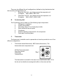
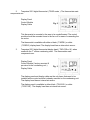
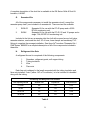
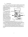
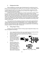
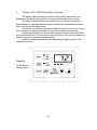
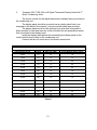
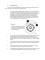
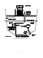
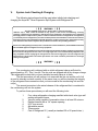
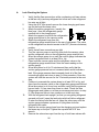
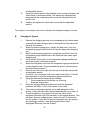
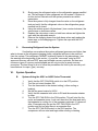
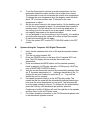
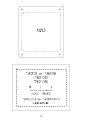
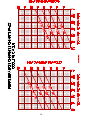
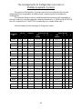
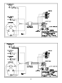
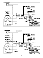
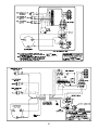
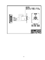
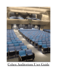
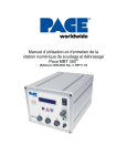
Direct Expansion Split
Marine Air Conditioning System
Installation, Operation & Maintenance
Table of Contents
I
Introduction . . . . . . . . . . . . . . . . . . . . . . . . . . . . . . . . . . . . . . . . . . . . . . . . . . . . . . . . . . . . . . . . . . 4
II
General Description of Basic Components
A.
Fan Coil . . . . . . . . . . . . . . . . . . . . . . . . . . . . . . . . . . . . . . . . . . . . . . . . . . . . . . . . 4
B.
Condensing Unit . . . . . . . . . . . . . . . . . . . . . . . . . . . . . . . . . . . . . . . . . . . . . . . . . 5
C.
Thermostats . . . . . . . . . . . . . . . . . . . . . . . . . . . . . . . . . . . . . . . . . . . . . . . . . . . . 5
D.
Seawater Pump . . . . . . . . . . . . . . . . . . . . . . . . . . . . . . . . . . . . . . . . . . . . . . . . . . 7
E.
Pump Relays . . . . . . . . . . . . . . . . . . . . . . . . . . . . . . . . . . . . . . . . . . . . . . . . . . . . 8
F.
Ducting, Grilles & Transition Boxes . . . . . . . . . . . . . . . . . . . . . . . . . . . . . . . . . . . 8
G.
Seawater Kits . . . . . . . . . . . . . . . . . . . . . . . . . . . . . . . . . . . . . . . . . . . . . . . . . . . 9
H.
Refrigerant Line Sets . . . . . . . . . . . . . . . . . . . . . . . . . . . . . . . . . . . . . . . . . . . . . . 9
I.
Basic Theory of System Operation . . . . . . . . . . . . . . . . . . . . . . . . . . . . . . . . . . 10
III
Installation of Basic Components
A.
Fan Coil . . . . . . . . . . . . . . . . . . . . . . . . . . . . . . . . . . . . . . . . . . . . . . . . . . . . . . .
B.
Condensing Unit . . . . . . . . . . . . . . . . . . . . . . . . . . . . . . . . . . . . . . . . . . . . . . . .
C.
Refrigerant Line Sets . . . . . . . . . . . . . . . . . . . . . . . . . . . . . . . . . . . . . . . . . . . . .
D.
Flaring Copper Tubing . . . . . . . . . . . . . . . . . . . . . . . . . . . . . . . . . . . . . . . . . . . .
E.
Thermostats . . . . . . . . . . . . . . . . . . . . . . . . . . . . . . . . . . . . . . . . . . . . . . . . . . .
F.
Seawater Pump . . . . . . . . . . . . . . . . . . . . . . . . . . . . . . . . . . . . . . . . . . . . . . . . .
12
17
18
18
19
22
IV
Before Starting the System for the First Time . . . . . . . . . . . . . . . . . . . . . . . . . . . . . . . . . . . . . . . 24
V
System Leak Checking and Refrigerant Charging
A.
Leak Checking the System . . . . . . . . . . . . . . . . . . . . . . . . . . . . . . . . . . . . . . . . 25
B.
Charging the System with Refrigerant . . . . . . . . . . . . . . . . . . . . . . . . . . . . . . . . 27
C.
Recovering Refrigerant from the System . . . . . . . . . . . . . . . . . . . . . . . . . . . . . 28
VI
System Operation
A.
Systems with AQS3 Thermostats . . . . . . . . . . . . . . . . . . . . . . . . . . . . . . . . . . . 28
B.
Systems with Tempwise 2001 Thermostats . . . . . . . . . . . . . . . . . . . . . . . . . . . 29
C.
Reverse Cycle System Limitations . . . . . . . . . . . . . . . . . . . . . . . . . . . . . . . . . . 30
VII
Maintenance
A.
B.
Fan Coil . . . . . . . . . . . . . . . . . . . . . . . . . . . . . . . . . . . . . . . . . . . . . . . . . . . . . . . 31
Seawater System . . . . . . . . . . . . . . . . . . . . . . . . . . . . . . . . . . . . . . . . . . . . . . . 31
VIII
Winterizing . . . . . . . . . . . . . . . . . . . . . . . . . . . . . . . . . . . . . . . . . . . . . . . . . . . . . . . . . . . . . . . . . 32
IX
General Warnings
X
Thermostat Cut-out Templates . . . . . . . . . . . . . . . . . . . . . . . . . . . . . . . . . . . . . . . . . . . . . . . . . . 33
XI
Refrigerant Charging Charts . . . . . . . . . . . . . . . . . . . . . . . . . . . . . . . . . . . . . . . . . . . . . . . . . . . . 34
XII
Refrigerant Line Set Sizing and Refrigerant Tee Arrangements . . . . . . . . . . . . . . . . . . . . . . . . . 35
XIII
System Wiring Diagrams . . . . . . . . . . . . . . . . . . . . . . . . . . . . . . . . . . . . . . . . . . . . . . . . . . . . . . . 38
. . . . . . . . . . . . . . . . . . . . . . . . . . . . . . . . . . . . . . . . . . . . . . . . . . . . . . . . . . . 32
I.
Introduction
Thank you for purchasing an Aqua-Air® Direct Expansion Split Marine Air
Conditioning System.
The purpose of this manual is to inform you of the different components that you
will need to install a fully operational direct expansion split air conditioning system on
your boat and to give you the basic information necessary to correctly install all of the
components that comprise the direct expansion split air conditioning system.
The Aqua-Air® direct expansion split air conditioning system have been
specifically designed for use in the marine environment. Systems are available in a
range of capacities from 5-48,000 BTU/H in either 115/1/60 or 230/1/60 voltage inputs
(the 24-48,000 BTU/H units are also available in 208-230/3/50-60 and 460/3/50-60 ). All
systems are rated for full capacity on 60 Hz power, however, they can be operated on
50 Hz power sources with a corresponding 17% decrease in capacity. The 50 Hz power
sources would normally be 100/1/50, 200-220/1/50, or 380/3/50. All of the systems are
available as reverse cycle units.
II.
General Description of Basic Components
There are six basic components that make up a typical Aqua-Air® marine self
contained system:
A.
Fan Coil
B.
Condensing Unit
C.
Thermostat
D.
Seawater Pump
E.
Pump Relay
F.
Ducting, Grilles and Transition Boxes
G.
Seawater Kit
H.
Refrigerant Line Sets
Following is a description of each major component.
A.
Fan Coil
The Fan Coil ( also referred to as an evaporator or air handler ) is a refrigerant to
air heat exchanger located in the area that is to be either cooled or heated. The basic
unit is made up of the following major components:
1.
Evaporator coil
2.
Capillary tube refrigerant metering device
3.
Squirrel cage blower and motor or propeller fan blade and motor
4.
Metal chassis with integral drain pan
4
There are two different fan coil configurations, defined only by the direction that
the air passes through the fan coil.
1.
Blow-thru Fan Coil - air is blown across the evaporator coil
Examples: AQB, AQBH, AQE, AQL
2.
Draw-thru Fan Coil - air is drawn across the evaporator coil
Examples: AQO, AQOC, AQOH, AQC
B.
Condensing Unit
The Condensing Unit is made up of the following major components:
1.
Refrigerant compressor
2.
Suction accumulator
3.
Reversing valve ( if it is a heat pump model )
4.
Base valves with service ports
5.
Condenser
6.
Electrical starting components for the compressor
7.
Drain pan & mounting base
C.
Thermostat
The thermostat / controller used to operate the unit can be provided in one of four
different configurations:
1.
Three knob manual thermostat ( AQS3 series thermostat ). The
thermostats main components are:
Off-Fan-Run mode switch
Fan speed control
Thermostat
Terminal block
Fig. 1
This thermostat is mounted in the area to be cooled/heated within 10' of
the fan coil so that the air sensing bulb will be in the return air flow.
5
2.
Tempwise 2001 digital thermostat ( TW2D series ). The thermostats main
components are:
Display Panel
Control Module
Display Cable
Fig. 2
This thermostat is mounted in the area to be cooled/heated. The control
module should be mounted close to the fan coil for ease of connecting the
fan motor.
The thermostat is available with either a black ( TW2DB ) or white
( TW2DW ) display head. The display head has an internal air sensor.
3.
Tempwise 2001 digital thermostat display head ( TW2-01B or W ) when
used with the ‘T’ series condensing units. The thermostats main
components are:
Display Panel
Control Module ( factory mounted &
pre-wired to the condensing unit )
Display Cable
Fig. 3
The display panel and display cable are the only items that need to be
installed as the control module is already mounted on the condensing unit.
The display head has an internal air sensor.
The display panel is available in either black ( TW2-01B ) or white
( TW2-01W ). The display head has an internal air sensor.
6
D.
Seawater Pump
The seawater pump is used to circulate seawater through the condenser on the
condensing unit(s). These are all centrifugal pumps and are NOT self priming. This
makes it necessary for the pump to be mounted below the ships running water line
(under all conditions).
A condensing unit requires approximately 250 GPH ( 946 LPH ) for every 12,000
BTU/H in capacity. Table 1 summarizes the amount of water necessary for a given
capacity.
Fig. 4
CP-05
Seawater
Pump
Condensing Unit Required Seawater Flow Rates
Unit Capacity, BTU/H
Seawater Flow in GPH / LPH
Seawater Pump
5,000 to 12,000
250 / 946
CP-02
12,001 to 24,000
500 / 1,892
CP-05
24,001 to 48,000
1,000 / 3,784
CP-10
48,001 to 72,000
1,500 / 5,677
CD100B-36-03C
72,001 to 144,000
3,000 / 11,353
CD100B-40-05C
Table 1
7
E.
Pump Relays
A pump relay is necessary when two or more condensing units are supplied
water from a single seawater pump. Aqua-Air® offers three different pump relays:
AQP2R
AQP6R
AQP8R
F.
Designed for use with two condensing units and one seawater
pump. Both condensing units must be on the same shore line. No
external power source is needed. This relay is not ignition protected
and therefore must not be used on a gasoline powered boat.
This relay is a solid state module which will control a single
seawater pump from as many as six separate condensing units.
This relay requires an external power source. Because it is solid
state it is ignition protected.
This relay is a solid state module which will control a single
seawater pump from as many as eight separate condensing units.
A separate trigger ( PEC-115 or 230 ) must be installed in the relay
for each condensing unit used. This relay requires an external
power source. Because it is solid state it is ignition protected.
Ducting, Grilles & Transition Boxes
Figure 5 Duct Kit Components
To transfer the air flow from the fan coil to the area that you want to heat or cool
you will need insulated flex duct, supply and return grilles, grille to flex duct transition
boxes and possibly adapter tees. These items can be purchased in kit form from AquaAir®. We offer the Economy Duct Kit series ( DKE ) which includes plastic grilles or the
Premium Duct Kit series ( DKP ) which includes wood ( teak ) framed grilles.
8
A complete description of the duct kits is available in the DK Series Grille & Duct Kit
brochure, # 81890.
G.
Seawater Kits
All of the components necessary to install the seawater circuit ( except the
seawater pump itself ) are included in a seawater kit. There are two kits available:
1.
SWK-05
2.
SWKU
Seawater Kit for use with the CP-02 pump and a 5,000
BTU/H condensing unit.
Seawater Kit for use with the CP-02, 05 and 10 pumps and a
single 7-24,000 BTU/H condensing unit.
Included in the kits are a seawater inlet thru hull with a speed scoop, ball valve,
seawater strainer, overboard thru hull, 25' of hose, hose clamps and necessary PVC
fittings to complete the average installation. See Aqua-Air® brochure “Seawater Kits /
SWK Series” #80625 for a complete description of all of the components included in
these kits.
H.
Refrigerant Line Sets
A refrigerant line set is comprised of the following components:
1.
2.
3.
4.
Seamless, refrigerant grade, soft copper tubing
Tubing insulation
Wire
Flare nuts
Each line set is shipped in the length requested with the tubing insulation and
flare nuts installed. If wire ( either 14/3 or 6 conductor ) is to be included it is bundled
along with the tubing.
Condensing Unit Refrigerant Line Set Sizes
Unit Capacity, BTU/H
Suction Line
Liquid Line
Line Set Series
5-12,000
3/8"
1/4"
LS12
16,000
1/2"
1/4"
LS16
20-24,000
1/2"
3/8"
LS24
30-36,000
3/4"
3/8"
LS36
Table 2
9
The LS series line set kits are available in a basic 10' length with 5' extensions up to a
maximum total length of 50'.
I.
Basic Theory of System Operation
Cooling Mode
Refrigerant is pumped from the condensing unit compressor as a high pressure,
high temperature gas through the reversing valve to the seawater condenser. In the
seawater condenser, the gas gives up ( rejects ) the heat acquired during compression
and from the system load to the seawater passing through the condenser. As this heat
is rejected to the water the gas changes state from a gas to a liquid. This liquid then
passes through the condensing unit liquid line base valve to the refrigerant line set. The
refrigerant line set then transports the liquid refrigerant to the fan coil capillary tube(s).
The liquid refrigerant passes through capillary tube(s) where it experiences a decrease
in pressure. As the lower pressure liquid refrigerant exits the capillary tube into the
evaporator it begins to absorb the heat contained in the air that is drawn ( or blown )
across the evaporator by the squirrel cage blower ( or propeller fan ), thereby ‘cooling’
the air that is then blown into the room. As the refrigerant absorbs the heat from the air
it begins to change state from a liquid back to a gas. This gas then passes back to the
condensing unit through the refrigerant line set to the condensing unit suction base
valve. It then passes through the the reversing valve and the suction accumulator back
to the compressor where the cycle begins again.
Heating Mode
In the heating mode the reversing valve solenoid is energized by the thermostat
and the solenoid changes position. This causes the flow of refrigerant to change
( reverse ). The evaporator in the fan coil is now the heat exchanger to reject the heat of
the unit and the seawater condenser is used as the evaporator to absorb the heat that is
available in the seawater. The hot gas from the compressor is pumped through the
reversing valve to the condensing unit base valve. It is then transported to the
evaporator coil ( which now is acting as the refrigerant condenser ) by the refrigerant
line set. Air is drawn ( or blown ) across the evaporator coil and then blown into the
room, producing the desired heating effect. As the refrigerant releases this heat to the
air it changes state from a gas to a liquid refrigerant. Upon exiting the evaporator
(condenser) the refrigerant passes through the capillary tube(s) where a drop in
refrigerant pressure occurs. The liquid/gas mixture then passes through the refrigerant
line set to the condensing unit base valve and into the condenser ( which is now acting
as the refrigerant evaporator ). Here, the liquid refrigerant begins to absorb the heat of
the water that is passing through the condenser ( evaporator ). As it absorbs this heat it
begins to change state from a liquid to a gas. This gas then passes through the
reversing valve and then the suction accumulator on its way back to the compressor
where the cycle begins again.
10
The refrigerant circuits for cooling and heating are shown in Figure 6.
Figure 6 System Refrigerant Flow Diagram
11
III
Installation of Basic Components
i i i WARNING i i i
FAILURE TO COMPLY WITH THE INSTALLATION INSTRUCTIONS
CONTAINED IN THIS MANUAL COULD PRODUCE HAZARDOUS
CONDITIONS RESULTING IN THE INJURY OR DEATH OF THE
OCCUPANTS AND THE DESTRUCTION OF THE BOAT. MAKE
SURE THAT THE WARNINGS ON THE LAST PAGE OF THE
MANUAL ARE FULLY UNDERSTOOD AND FOLLOWED.
ALL INSTALLATION TECHNIQUES SHOULD COMPLY WITH THE
ABYC “STANDARDS FOR RECOMMENDED PRACTICES FOR
SMALL CRAFT” SECTION A-6 and E-8.
IF THERE ARE ANY PARTS OF THIS MANUAL THAT ARE NOT
CLEAR PLEASE CONTACT Aqua-Air® FOR FURTHER ASSISTANCE.
i i i i i
A.
Fan Coils
Fan coils are ideally suited for installations in closets, under bunks or seats.
THEY SHOULD NEVER BE MOUNTED IN THE ENGINE ROOM OR
BILGE AREA WHERE THEY COULD DRAW TOXIC FUMES INTO
THE UNIT AND THEN DISCHARGE THEM INTO THE LIVING AREA.
In all applications the fan coil should be installed so that the air discharge is at
least three feet above the floor. The best possible location is to have the air discharging
at or near the ceiling level. The reason for mounting the air discharge as high as possible
is because cold air is denser than ambient air and its natural tendency is to fall to the
lowest point in the room after leaving the discharge grille.
12
Figure 7 Typical Draw-Thru Fan Coil Installations
The unit must be mounted with the drain pan at the bottom of the unit as
condensate from the evaporator is collected here.Each fan coil has two drain fittings that
connect into a common tee. The drain line ( minimum ½" ID ) should be run either
overboard or into a shower sump. It is not advisable to run the drain lines into the bilge
where the condensate can become stagnant and foul smelling when mixed with
seawater. On a hot, humid day several pints of water can be removed from the air by the
self contained unit.
Figure 8 Overhead Blow-thru Fan Coil Installation
13
Insulated flex duct should be connected to the plastic blower discharge collar by
first pulling back about two inches of the insulation on the end of the flex duct that you
are going to attach to the blower. Slip the inner duct over the collar so that at least one of
the duct reinforcing wires is up against the flat part of the collar. Install three sheet metal
screws around the perimeter of the collar to hold the duct in place. Wrap a piece of duct
tape around the duct that is on the collar. Slip the duct insulation back over the duct that
is attached to the collar and duct tape in place.
The correct minimum grille sizes for each fan coil are shown in Table 2. Return
air grilles can be larger than listed ( this is one case where bigger is better), however,
supply grilles should not be any larger than 25% over the recommended sizes. A supply
grille that is too large will not properly disperse the air into the room causing hot spots. In
either case the grilles must NOT be any smaller than the minimums listed. Small grilles
cause decreases in system performance, fan coil icing or ( in the heating mode ) unit
shut down due to high head pressures.
Minimum Grille and Flex Duct Sizes
Model Number
Supply Grille
in2 / cm2
Return Grille
in2 / cm2
Minimum Duct
Diameter, in/mm
AQO-04,5
32 / 206
64 / 412
4" / 100mm
AQO-07,8
40 / 258
72 / 464
5" / 125mm
AQO-10
48 / 309
100 / 645
5" / 125mm
AQO-12
AQOC-12
AQC-12
60 / 387
120 / 774
6" / 150mm
AQO-16
AQOC-16
AQC-16
AQC-16L
72 / 464
144 / 929
6" / 150mm
AQOH-20,24
120 / 774
200 / 1290
8" / 200mm
AQOH-30,36
160 / 1032
288 / 1858
10" / 250mm
AQB-04,5
8" x 8"
20cm x 20cm
64 / 412
NONE
AQB-07,8
8" x 8"
20cm x 20cm
72 / 464
NONE
AQB-10
10" x 10"
25cm x 25cm
100 / 645
NONE
AQB-12
AQBH-12
12" x 12"
30cm x 30cm
120 / 774
NONE
14
Minimum Grille and Flex Duct Sizes
AQB-16
AQBH-16
12" x 12"
30cm x 30cm
144 / 929
NONE
AQL-12
AQE-12
8" x 16"
20cm x 40cm
120 / 774
NONE
AQL-16
AQE-16
8" x 16"
20cm x 40cm
144 / 929
NONE
Table 3
It is very important that there is adequate space for air to return to the fan coil.
While the fan coil does not have to be directly behind the return air grille there must be
an air path of the same area between the return air grille and the fan coil. Never mount
the front of the fan coil any closer than two inches from a bulkhead as this will restrict the
air flow into the unit.
A return air filter must be in place on the return air grille. This will prevent dirt and
lint from being drawn into the fan coil, reducing performance. The most common type of
filter material is an expanded aluminum type. This is the type used on all return air grilles
supplied by Aqua-Air® that have return air filters. These filters should be checked on a
monthly basis, during normal usage, and cleaned as necessary.
15
WARNING
TO AVOID AN ELECTRICAL SHOCK FROM A PIECE OF EQUIPMENT THAT
HAS DEVELOPED AN INTERNAL SHORT ALWAYS GROUND ANY
AQUA-AIR® SYSTEM IN THE MANNER DESCRIBED BELOW:
1.
2.
3.
4.
5.
6.
7.
8.
9.
USE SUITABLE SIZED WIRE ( SEE TABLE 4 ) WITH A GROUND WIRE
TO FEED POWER TO:
a.
AQS1 or AQS3 SERIES THERMOSTAT or
b.
TEMPWISE 2001 THERMOSTAT or
c.
CONDENSING UNIT EQUIPPED WITH A TEMPWISE or
d.
CONDENSING UNIT WITH INTERNAL POWER RELAY
MAKE SURE THAT THE GROUND WIRE IS CONNECTED ON THE
OTHER END AT THE CIRCUIT BREAKER PANEL.
CONNECT A GROUND WIRE FROM THE FAN COIL(S) TO THE
THERMOSTAT GROUND LUG.
CONNECT A GROUND WIRE FROM THE SEAWATER PUMP TO THE
GROUND LUG ON THE CONDENSING UNIT OR PUMP RELAY
CONNECT A GROUND WIRE BETWEEN THE PUMP RELAY (IF USED)
AND CONDENSING UNIT GROUND LUG.
CONNECT A BONDING STRAP BETWEEN THE CONDENSING UNIT
GROUND LUG AND THE SHIPS BONDING SYSTEM.
CHECK FOR CONTINUITY BETWEEN ALL OF THE ABOVE POINTS.
USE CORRECTLY SIZED WIRE TERMINALS FOR ALL CONNECTIONS.
USE ONLY WIRE CRIMPING TOOLS THAT ARE MANUFACTURER
APPROVED FOR THE WIRE TERMINALS USED.
ALL WIRING SHOULD COMPLY WITH THE ABYC “STANDARDS FOR
RECOMMENDED PRACTICES FOR SMALL CRAFT” SECTION E-8.
FAILURE TO COMPLY WITH THE ABOVE INSTRUCTIONS
CAN RESULT IN SERIOUS INJURY OR DEATH
16
B.
Condensing Units
The Aqua-Air® condensing units are designed for installation in almost any area of
the boat. They are unaffected by moisture, vibration or ambient temperatures up to 140/
F ( 60/C ). They should not, however, be installed in a location where they will be
sprayed with seawater ( such as under an engineroom air inlet). They are also designed
to withstand the severe jolts
that can be encountered by a
boat when it is in a heavy sea.
All of the refrigerant
components are hermetically
sealed.
The condensing units
can be installed wherever there
is sufficient space. Install the
unit in a location where it is
easily accessible for service.
The plywood base that is at the
bottom of the unit is not a
shipping base. It is meant to
stay on the unit to provide a
means of securely fastening the
unit down to whatever surface it
is mounted on. Use a minimum
of four screws to hold the unit in
place. It should be fastened in
Figure 9 Typical Condensing Unit
such a way as to allow easy
removal in case service is needed at a later date.
The condensing unit is connected to the seawater hoses coming from the
seawater pump and going to the seawater overboard fitting. The hose should be (at a
minimum) 5/8" ID, single braid hose. Insert the hoses on the seawater condenser tubes
a minimum of 1-1/2" and clamp in place with a stainless steel hose clamp.
Connect a drain hose to the drain pan connection on the front of the condensing
unit. This drain hose can then be run into a shower sump or overboard.
Connect the wiring from the condensing unit to the fan coil, thermostat, pump
and/or pump relay and circuit breaker panel (when applicable) according to the correct
wiring diagram for the system. Verify that all components are properly grounded and
bonded.
17
C.
Refrigerant Line Sets
When installing the connecting copper tubing between the condensing unit and
the fan coil(s) several things must be kept in mind. The only type of copper tubing to use
is refrigerant grade seamless soft copper. The maximum length of any line set is 50'
(15.2m). The lines can be run in any manner i.e. up, down or at an angle. Try to avoid
sharp bends as the tubing kinks easily.
Insulate both lines ( suction and liquid ) on reverse cycle systems and the suction
line only on cooling only systems. Both refrigerant lines should never be insulated
together in the same piece of insulation. When putting insulation on the copper lines tape
the ends over to prevent anything that is in the inside of the insulation from entering the
copper line. While running the lines throughout the boat the ends should remain taped
over to prevent debris from entering the lines. All of the joints where the insulation meets
should be taped to seal these joints. This will prevent condensation from forming on the
outside of the line set.
The connections at the condensing unit and fan coil are made using flare fittings.
These connections must be made with the greatest of care. The flare fittings that are
used are of the 45/ single flare type. Double flares are not compatible with this type of
flare joint and should never be used. When the flare is properly made it should be large
enough in diameter to fill the inside of the flare nut.
D.
Flaring Copper Tubing
Following is the accepted procedure for flaring copper refrigeration tubing for use
with 45/ refrigeration flare fittings:
1.
2.
3.
4.
Use a copper tube tubing cutter to get a good square cut on the end of the
tubing to be flared. Never cut the tubing with a hacksaw.
Ream the inside of the tube to remove any burrs. Make sure that none of
the copper filings fall
inside of the tube.
Place the flare nut on the
tube with the threaded
end of the flare nut facing
the end of the tubing to
be flared.
Insert the tubing in the
flaring block as shown in
Figure 10. The tubing
should extend no more
than 1/3 of the depth of
the flare block flare. If too
much tubing extends
above the block then the
Figure 10 Flaring Copper Tubing
flare will be too large and
18
the flared tube will not fit into the flare nut. If not enough tubing extends above the block
then the flare will be too small and will be squeezed out of the flare upon tightening
causing the connection to leak refrigerant.
5.
To form the flare place a drop of refrigerant oil ( no other type of oil is
acceptable ) on the end of the flaring tool spinner. Turn the spinner into the
tube three quarters of a turn then back one quarter. Continue this until the
spinner will no longer turn.
6.
Remove the flaring block and pull the flare nut up and over the flared end
of the copper tubing. Verify that the flare fills the interior flared portion of
the flare nut.
E.
Thermostats
1.
AQS1 and AQS3 Series Thermostat / Switch Assemblies
The thermostat switch assembly is the central distribution point for the split
system electrical power.
The control panel should be mounted over a suitably sized hole ( see
templates in the back of the manual ) using four screws. The plastic cover for the
rear of the control must be installed to prevent someone from accidentally
touching the exposed electrical connections.
The wires extending from
the back of the control panel end in
a terminal strip which should be
securely mounted. After all of the
wiring is completed, the covers that
Fig. 11
were supplied with the control
panel (one for the terminal strip
AQS3
and one for the back of the control)
Series
must be installed.
Thermostat
The copper temperature
sensing bulb must be mounted in
the return air flow to the fan coil.
There are two plastic clips on the
face of the fan coil that are
specifically for mounting this
sensor. The sensing bulb must never be mounted with the bulb in direct contact
with the fan coil. The bulb should not be mounted on a surface that would be
warmer than the surrounding air ( i.e. an engine room bulkhead or the hull side ).
19
2.
Tempwise 2001 TW2D Series Digital Thermostat
The display panel should be mounted over a suitably sized hole ( see
templates in the back of the manual ) using the double-sided tape provided.
The display head should not be mounted in an area that is exposed to
direct sunlight or other heat sources as this will affect the air temperature sensor
that is mounted in the display head.
The control module box should be mounted close to the fan coil so that the
fan motor wire can easily be attached to the control module terminal block.
All wiring connections for the unit will be made on the terminal strip inside
the control module box. Connect the fan coil motor wire to the control module box.
Replace the control module cover after wiring.
Install the display cable phone wire connecting the display panel to the
control module box.
Figure 12
TW2D Series
Display Head
20
3.
Tempwise 2001 TW2-01B or W Digital Thermostat Display Head with ‘T’
Series Condensing Units
The control module for the digital thermostat is already factory mounted on
the condensing unit.
The display panel should be mounted over a suitably sized hole ( see
templates in the back of the manual ) using the double-sided tape provided.
The display head should not be mounted in an area that is exposed to
direct sunlight or other heat sources as this will affect the air temperature sensor
that is mounted in the display head.
Install the display cable phone wire connecting the display panel to the
control module box located on the condensing unit.
Connect the fan coil motor wire to the control module box.
Recommended Wire and Circuit Breaker Sizes
Unit Capacity BTU/H
Voltage
Wire Size AWG
Circuit Breaker Rating, Amps
5,000
115
14
10
7,000
115
14
15
10,000
115
12
20
12,000
115
12
20
16,000
115
10
30
7,000
230
14
10
10,000
230
12
15
12,000
230
12
15
16,000
230
12
20
20,000
230
12
20
24,000
230
12
20
30,000
230
10
30
36,000
230
10
30
Table 4
21
F.
Seawater Pumps
The seawater pumps supplied by Aqua-Air® are all centrifugal, non-self priming
pumps. They must be installed in the following manner:
1.
The pump must be mounted securely at a point in the hull that is beneath
the waterline of the boat under ALL conditions ( at rest, under way or in a
heavy sea ). The position of the pump should be as close as possible to the
centerline of the boat, no further forward than the front of the engine
compartment and no further aft than the propeller stuffing boxes or aft
engine compartment bulkhead. Mount the pump as low as possible in the
hull. The pump should always be mounted in a horizontal position and
never on its head or end. See Figure 5 below.
Figure 13
Seawater Pumps can be mounted
in any horizontal position (within
the range shown at right) and will
still be self-purging.
2.
To make the system self purging there must be a steady uphill run from the
seawater inlet to the seawater strainer through the pump up to the
condensing unit and then overboard ( See Figure 14 ). This will allow any
air that enters the seawater inlet to bleed off naturally through the seawater
system.
3.
Connect the pump wire to the condensing unit according to the applicable
wiring diagram. The ground wire must be connected to the green ground
lug.
4.
On a system with more than one condensing unit connected to a single
seawater pump the pump will be wired to the pump relay.
5.
The seawater pumps CANNOT be run without a supply of water. If they are
run dry internal damage will be caused voiding the pumps warranty.
22
Figure 14 Typical Seawater Circuit
23
IV.
Before Starting the System for the First Time
Below is a preliminary check list that should be verified before operating the
system for the first time:
1.
2.
3.
4.
5.
6.
7.
8.
9.
10.
11.
12.
13.
14.
15.
16.
17.
18.
19.
20.
The fan coil is securely fastened in place.
The supply and return air grilles meet the minimum area requirements
There is a return air filter installed
The insulated duct is installed with a minimum of bends and without any kinks that
would restrict the air flow.
All electrical covers ( either on the thermostat or the condensing unit ) are in
place.
The thermostat temperature sensing bulb or sensor is in the return air flow but not
touching the evaporator coil or housing.
The fan coil drain pan is draining properly. This can be checked by pouring water
into the pan and verifying that it drains.
All wire harnesses or phone wires connecting the thermostat or display head are
properly connected to the unit or the control module box.
The flare joints on the condensing unit and fan coil have been made according to
the Aqua-Air® instructions
The pump and/or pump relay wires are correctly connected to the condensing
unit.
The electrical power line from the ship’s distribution panel is properly connected to
the thermostat ( AQS1 or AQS3 or TW2 ) or to the condensing unit according to
the applicable wiring schematic for the equipment used. Make sure that a time
delay type circuit breaker is used.
The copper refrigerant lines connecting the condensing unit to the fan coil unit are
properly insulated and sealed. The line set should be fastened every 18" (.5m)
throughout the vessel.
The condensing unit is securely fastened down and is accessible for service.
The flare nuts on the fan coil are insulated. This should be done after checking the
system for leaks.
The seawater system is piped in the recommended way so as to be self purging
of air.
The pump is mounted well below the waterline of the boat.
There should be a properly sized seawater strainer between the seawater inlet
and the pump.
The seawater inlet is a scoop type with the open portion of the scoop facing
forward.
There should be a separate overboard fitting for each condensing unit. It should
be mounted no more than 2" above the waterline.
The seawater inlet should be no further than 6" from the centerline of the boat.
24
V.
System Leak Checking & Charging
The following instructions should be used when initially leak checking and
charging the Aqua-Air® Direct Expansion Split System with Refrigerant 22.
i i i WARNING i i i
Title VI of the EPA Clean Air Act, Section 608.c.1 states the following:
“Effective July 1, 1992, it shall be unlawful for any person, in the course of maintaining, servicing,
repairing, or disposing of an appliance or industrial process refrigeration, to knowingly vent or otherwise
knowingly release or dispose of any Class I or Class II substance used as a refrigerant in such appliance
( or industrial process refrigeration ) in a manner which permits such substance to enter the environment.
De minimis releases associated with good faith attempts to recapture and recycle or safely dispose of any
such substance shall not be subject to the prohibition set forth in the preceding sentence.”
Personnel handling Refrigerant 22 ( which is classified as a Class II substance ) must be EPA certified and
must use EPA approved refrigerant recovery equipment.
In the past it was an accepted practice to use the refrigerant contained inside the condensing unit to purge
®
the air from the refrigerant line sets. This is no longer legal and is not recommended by Aqua-Air . The
only acceptable means of purging the refrigerant line sets and charging the unit with refrigerant are
outlined below. Any deviation from these procedures can result in Federal prosecution for the illegal
venting of refrigerants.
i i i WARNING i i i
The condensing unit is shipped with an initial refrigerant charge sufficient for
approximately a 30' ( 10m ) line set. The fan coils are shipped with a dry nitrogen charge.
The refrigerant line sets that you have installed currently have air in them.
The first procedure you will perform is to evacuate the line set and fan coil of all
air and its inherent moisture content. At the same time you will be checking the integrity
of the refrigerant flare connections that you have made at the condensing unit and fan
coil(s).
The second procedure is the actual release of the refrigerant that is contained in
the condensing unit into the system.
To perform these procedures you will need the following tools:
1.
2.
3.
4.
5.
6.
7.
Four valve refrigeration charging manifold with check valve type self
sealing refrigerant hoses.
Vacuum pump capable of evacuation down to at least 25 microns.
Ratchet wrench with a 1/4" square opening
9/16" box wrench
Adjustable wrench
Thermometer
Can of Refrigerant 22 ( usually a standard 30 or 50 pound drum )
25
A.
Leak Checking the System
1.
2.
3.
2.
3.
4.
5.
6.
7.
8.
9.
10.
11.
12.
Verify that the flare connections at the condensing unit base valves,
at the fan coil(s) and any refrigerant tee’s that are in the refrigerant
line sets are all tight.
Using the 9/16" box wrench remove the lower charging port brass
cap on the liquid line base valve.
Attach the suction gauge hose ( usually the
blue hose ) from the refrigeration gauge
manifold set to the charging port.
Attach the vacuum hose from the refrigeration
gauge manifold set to the vacuum pump.
Attach the refrigerant hose from the
refrigeration gauge manifold set to the can of refrigerant. The valve
on the refrigerant can should remain in the OFF (counter clockwise)
position.
Verify that all hose connections are tight
Turn the vacuum pump on and fully open both the vacuum valve
and the refrigerant valve on the refrigeration gauge manifold set.
Allow the vacuum pump to run until the suction gauge indicates the
system has pulled down to at least 28 in. Hg.
Close both the vacuum valve and the refrigerant valve on the
refrigeration gauge manifold set. Note the exact reading on the
suction gauge.
Allow the system to sit for 15 minutes and then verify that the
suction gauge pressure has not increased which would indicate a
leak. If the gauge pressure has increased check all of the flare
connections again and return to step 6 of this procedure. Once the
system will hold the vacuum for the 15 minutes proceed to the next
step.
Continue to evacuate the system down to at least 29.5 in Hg. and
then close the vacuum valve on the refrigeration gauge manifold set.
Allow the system to sit for an hour and then verify that the pressure
has not risen. If it has risen then there is a leak. Check the flare
fittings again and tighten or re-flare as necessary and return to step
6. If the pressure has not risen continue on to the next step.
With the refrigerant tank upright ( so that you are getting refrigerant
gas and not liquid ) open the tank valve which will allow refrigerant
to enter the line set and the fan coil. Keep the valve open until the
suction gauge indicates a pressure of 0 psig then close the
refrigerant tank valve.
Remove the suction gauge hose from the charging port and replace
the brass cap on the port. Tighten the cap with the 9/16" box
wrench.
Remove the valve stem caps from the top of both base valves with
26
13.
14.
an adjustable wrench.
Using the ratchet wrench fully backseat ( turn counterclockwise ) the
valve stems on both base valves. This allows the refrigerant that
was stored in the condensing unit to enter the refrigerant line set
and fan coil.
Replace and tighten the valve stem covers with the adjustable
wrench.
The system is now ready to be run to verify that the refrigerant charge is correct.
B.
Charging the System
1.
2.
3.
4.
5.
6.
7.
8.
9.
10.
11.
Remove the charging port cap on the condensing unit suction base
valve and the upper charging port on the liquid line base valve with
the 9/16" box wrench.
Attach the suction gauge hose ( usually the blue hose ) from the
refrigeration gauge manifold set to the suction base valve charging
port.
Attach the discharge gauge hose ( usually the red hose ) from the
refrigeration gauge manifold set to the liquid line base valve upper
charging port.
Verify that all of the valves on the refrigeration gauge manifold set
are in the closed ( clockwise ) position.
Attach the refrigerant hose from the refrigeration gauge manifold set
to the refrigerant tank ( this may already be done if continuing from
the leak check procedure ).
Remove the valve stem caps from the top of both base valves with
an adjustable wrench.
Frontseat ( turn clockwise ) both valve stems one full turn. This will
allow pressure to enter the refrigeration gauge manifold set.
Using the thermometer measure the following:
1.
Room temperature that the fan coil is serving
2.
Seawater temperature
Using the charging tables provided verify that the refrigerant
pressures fall within ± 10% of the values on the chart.
If the suction refrigerant pressure is low add refrigerant to the
system. If they are within the normal parameters then go to step 14.
To add refrigerant to the system first open the valve on the
refrigerant tank and verify that the tank is in the upright position. This
will insure that only refrigerant gas ( and not liquid ) is introduced
into the system. If you need to remove refrigerant from the system (
an overcharge condition ) see the separate section titled “
Refrigerant Recovery from the System”.
27
12.
13.
14.
15.
16.
C.
Slowly open the refrigerant valve on the refrigeration gauge manifold
set. This will begin to allow refrigerant into the system. Continue to
do this at short intervals until the system pressures are within
parameters.
Once the system is fully charged close the valve on the refrigerant
tank and verify that the refrigerant valve on the refrigeration gauge
manifold set is closed.
Using the ratchet wrench fully backseat ( turn counterclockwise ) the
valve stems on both base valves.
Replace the valve stem covers on both base valves and tighten the
caps with the adjustable wrench.
Remove the charging hoses from both base valves and replace the
brass caps on the charging ports. Tighten the caps with the 9/16"
box wrench.
Recovering Refrigerant from the System
If a situation occurs where the system refrigerant pressures are higher than
what is shown on the refrigerant charging charts, refrigerant will have to be removed
from the system. This refrigerant CANNOT be directly vented to the atmosphere ( see
the warning at the beginning of this section ). It must be “recovered” using an EPA
approved recovery unit and DOT approved refillable recovery cyclinder. As there are
numerous types of recovery units available we will not give you an exact recovery
procedure. The best thing to do is to follow the procedures set forth by the recovery unit
manufacturer for vapor ( gas ) recovery.
VI.
System Operation
B.
Systems Using the AQS1 or AQS3 Series Thermostat
1.
2.
3.
4.
5.
6.
7.
Verify that the OFF-FAN-RUN switch is in the OFF position.
Turn the unit circuit breaker ON.
Turn the thermostat to the desired setting ( either cooling or
heating).
Set the fan speed control to HIGH
Verify that the seawater inlet valve is ON and the seawater strainer
is clean.
Turn the OFF-FAN-RUN to the FAN position. This will start the fan
motor and seawater pump. Look over the side of the boat and verify
that seawater is coming out of the seawater overboard. If it does not
after 15 seconds stop the put the OFF-FAN-RUN in the OFF
position and find out why there is no seawater flow.
Turn the OFF-FAN-RUN switch to the RUN position. The
compressor will now start and begin either cooling or heating.
28
8.
9.
10.
11.
B.
To set the thermostat to maintain a certain temperature, turn the
thermostat toward the center position until a single click is heard.
The thermostat is now set to maintain the current room temperature.
To change the room temperature by a few degrees rotate the knob
about 1/8" at a time and then wait 15 minutes for the room
temperature to adjust.
Set the fan speed control to the desired setting. On the heating cycle
run the fan on low speed for about 15 minutes and then increase to
medium speed. This will allow the unit to build up temperature. In
the cooling cycle the fan can be run at any speed. In either mode
unit capacity decreases as fan speed decreases.
It is not advisable to turn the system on and off rapidly. It is usually a
good idea after turning the system off to allow at least five minutes
to pass before starting the unit again.
To turn the system OFF turn the OFF-FAN-RUN switch to the OFF
position.
Systems Using the Tempwise 2001 Digital Thermostat
1.
2.
3.
4.
5.
6.
7.
Verify that the seawater inlet valve is ON and the seawater strainer
is clean.
Turn the unit circuit breaker ON.
Press the POWER button on the face of the Tempwise 2001 one
time. The LED display will now indicate the current room
temperature.
Press and release the MODE button until the desired operating
mode is reached ( AUTOmatic operation, COOLing only, HEATing
only or MOISTURE CONTROL mode).
View the current thermostat set point by momentarily pressing either
the
(increase temperature) or
(decrease temperature) key. To
change the set point continue to press the
or
key until the
desired set point is reached.
Fan speed operation initially is in the AUTO(matic) mode. This
means that the fan speed will be automatically selected based upon
how close the room temperature is to set point. The fan speed will
be at its lowest setting at set point. To change the fan speed setting
press the FAN key until the desired fan speed is achieved.
Continuing to hold the FAN key will scroll through the six fan speeds
and then return to the AUTOmatic mode.
For further operating information on the TW2 thermostat please refer
to the thermostat operation manual.
29
C.
Reverse Cycle Systems
Most Aqua-Air® units are reverse cycle heat pump units. This type of
system derives its heat from the seawater that is pumped through the
seawater condenser. When the water temperature reaches 40°F there is
an approximate 50% loss in heating capacity. As the water temperature
reaches 35°F there will be little or no heating available. This should be kept
in mind when considering the practicality of a reverse cycle system for the
area that you will be operating in during the winter months.
30
VII
VIII
Maintenance
A.
Fan Coils
1.
The fan motors should be lubricated on a yearly basis with SAE 20
oil
2.
The drain pans should be checked for proper drainage by pouring a
quart of water into the pan. The water should drain within thirty
seconds.
3.
Clean all return air filters at the beginning of the boating season and
then regularly on a monthly ( or sooner as use dictates ) basis.
B.
Seawater System
1.
The seawater pump requires no maintenance
2.
The seawater strainer should be cleaned at the beginning of the
boating season and then regularly on a monthly ( or sooner as use
dictates ) basis.
Winterizing
Condensing Unit.
Turn the seawater inlet off. Remove the seawater hose from the seawater
pump outlet. This will allow the water to drain from the unit as long as the
system is piped correctly.
Seawater Pump
With the seawater inlet off loosen the screws on the front of the pump. This
will allow any water in the pump head to drain.
Seawater Strainer
Drain and clean the strainer
Seawater Inlet
Remove the hose at the inlet valve and remove as much water from the
valve as possible.
Seawater Outlet
Remove the hose at the seawater outlet. Install a cap over the fitting to
prevent any water from entering the fitting.
31
i i i WARNING i i i
Aqua-Air Manufacturing ( a division of the James D. Nall Company, Inc. ) hereafter referred to as the
“Manufacturer” makes the following warnings in regard to the use of its products. Even though these
warnings are comprehensive in nature, there are certain dangers that might arise which, at this time, are
unforeseeable. A thorough understanding of the dangers outlined below will help as a guide for spotting
other potentially dangerous situations. This understanding is very important in assuring your safety.
Electricity
Aqua-Air® products operate on voltages ranging from 24 to 480 volts of alternating current (A.C.) Power. Because of the
danger involved with these voltages, all metal components ( bases, cabinets, units ) must be grounded in some manner
to the ship’s grounding system. Some of the relays, switches and thermostats used in the Aqua-Air® systems are not
ignition protected. Because of this, the ventilation blower on a boat should be run for five minutes prior to and during the
operation of any Aqua-Air® product or system. All electrical connections must be sealed or covered in such a way as to
prevent contact by unauthorized personnel. Such contact could lead to permanent injury or death.
Electrolysis
Any electrical leakage of a component can cause electrolysis. This could lead to a deterioration of a thru-hull which could
cause leakage of water into the boat which could result in sinking the boat. All Aqua-Air® products must be kept clean and
dry. They should be periodically inspected for electrical leakage. If detected, the faulty component should either be repaired
or replaced.
Refrigerant
All Aqua-Air® products utilize refrigerant 22 ( monochlorodifluoromethane ). This refrigerant is non-toxic and non-flammable.
This refrigerant contains no oxygen and will therefore no support life. When burned this refrigerant deteriorates into
potentially lethal gases. If a refrigerant leak is discovered, evacuate all personnel from the are and prohibit the use of any
item using an open flame. Due to the high pressures involved in refrigeration systems, eye protection, gloves and longsleeved clothes should be worn during servicing of a system. Extensive frost burns can occur to the eyes and skin if they
come into contact with liquid refrigerant.
Ventilation
To either cool or heat air, Aqua-Air® systems move air through a heat exchanger by means of either a propeller fan or
blower system. This process naturally causes a suction on one side of the unit and a pressurized area on the other. These
heat exchangers or “cooling units” as they are referred to in our brochures must be installed so that this suction-pressure
action does not (1) pressure an area to the extent of causing structural failure of the area which could cause injury and
does not (2) cause a suction in an area where vapors from batteries, fuel or other operating equipment exist. If a cooling
unit were installed in this way then these vapors could possibly be discharged into a living space where they could be
hazardous. The best way to prevent the introduction of dangerous gases into a living space is to make sure all living spaces
are carefully sealed from all other spaces. It is never advisable to completely seal an area without some sort of auxiliary
ventilation in the event of lethal gas or fumes escaping from any source.
Condensate
All Aqua-Air® direct expansion cooling units and self contained units produce condensate when operated in the cooling
mode. The self contained units and condensing units can produce condensate during operation in the heating mode. This
water must be drained overboard. If allowed to drip on a wood, dry rot can form causing structural failure. If allowed to drip
on electrical components, deterioration of the components can occur. When the cooling unit is in operation, a negative
pressure is exerted on the condensate line. Always locate condensate outlets as far as possible from sources of fumes
or dangerous gases. These fumes or gases could be drawn into the system due to this negative pressure resulting in a
potentially hazardous situation.
i i i WARNING i i i
Never sleep in an enclosed area in a boat when any equipment, which functions as a direct result of the
combustion of a volatile fuel, is in operation ( such as engines, generators, oil-fired heaters, etc. ). At any
time their exhaust system could fail leading to a build-up of dangerous gases within the enclosed area.
32
33
34
Refrigerant Line Set Sizing
35
Tee Arrangements for Refrigeration Line Sets on
Multiple Evaporator Systems
The purpose of this guide is to show some of the recommended line set and
refrigeration tee arrangements for different size condensing unit and evaporator
combinations.
The important thing to note on multiple evaporator systems is the orientation of
the tee’s when you have an evaporator capacity mismatch i.e. a 4,000 and 8,000 BTU/H
fan coil connected to a 12,000 BTU/H condensing unit ( shown below right ).
See the drawing on the next page for Diagram A and B.
FAN COIL
CONDENSING
UNIT
1
2
10,000
5,000
5,000
12,000
7,000
DIAGRAM
SUCTION LINE TEE
LIQUID LINE TEE
PART
NUMBER
A
B
C
PART
NUMBER
A
B
C
A
131210-06
3/8"
3/8"
3/8"
131209-04
1/4"
1/4"
1/4"
5,000
B
131210-06
3/8"
3/8"
3/8"
131209-04
1/4"
1/4"
1/4"
8,000
4,000
B
131210-06
3/8"
3/8"
3/8"
131209-04
1/4"
1/4"
1/4"
8,000
8,000
A
131310-06
3/8"
3/8"
½"
131209-04
1/4"
1/4"
1/4"
12,000
4,000
B
131310-08
½"
3/8"
3/8"
131209-04
1/4"
1/4"
1/4"
10,000
10,000
A
131310-06
3/8"
3/8"
½"
131301-04
1/4"
1/4"
3/8"
12,000
8,000
B
131310-08
½"
3/8"
3/8"
131301-06
3/8"
1/4"
1/4"
16,000
4,000
B
131311-13
½"
½"
3/8"
131301-06
3/8"
1/4"
1/4"
12,000
12,000
A
131310-06
3/8"
3/8"
½"
131301-04
1/4"
1/4"
3/8"
16,000
8,000
B
131311-13
½"
½"
3/8"
131301-06
3/8"
1/4"
1/4"
20,000
4,000
B
131311-13
½"
½"
3/8"
131310-04
3/8"
3/8"
1/4"
30,000
20,000
10,000
B
131312-01
3/4"
½"
3/8"
131310-04
3/8"
3/8"
1/4"
36,000
20,000
16,000
B
131311-12
3/4"
½"
½"
131310-04
3/8"
3/8"
1/4"
24,000
12,000
B
131312-01
3/4"
½"
3/8"
131310-04
3/8"
3/8"
1/4"
16,000
20,000
24,000
36
37
38
39
40
41
42
43
44
45
46
47
48
49
50
DX PRODUCT LIMITED WARRANTY PERIODS
The warranty period on all Aqua-Air DX (Direct Expansion) products is one year. Parts and labor are
covered per warranty allowance schedules.
For new Aqua-Air DX system installations using TW2 microprocessor controls, parts will be warranted
for an additional year. All equipment in the system, including pumps, pump relays and associated parts
will be covered for two years.
The TW2 microprocessor controls used in a retrofit on Aqua-Air or any other manufacturer’s marine air
conditioning equipment will carry a one year warranty. New TW2 controls or components of the
microprocessor control system purchased to replace out of warranty controls or components will have a
one year warranty.
Non-warranty replacement parts and components, other than TW2 controls or components, will be
warranted for a period of 90 days. This warranty is for parts only, no labor is included. The exception
to this category is replacement compressors which carry a one year warranty, including parts and labor
from the date they were sold.
Parts and components supplied by Aqua-Air Manufacturing for replacement on any Aqua-Air unit under
warranty will be warranted for the remainder of the original warranty period only.
Replacement parts or components used on competitors equipment will have a 90 day warranty. The
exception is those parts used in the refrigeration circuit of any competitive brand of air conditioning
equipment, which will carry no warranty.
All warranties begin when the customer takes possession of the equipment. The warranty is extended
to all owners of the equipment commencing the date the original owner takes possession of it.
Verification of original purchase will be required. All warranties are limited to the terms and periods set
forth here. Any and all implied warranties are excluded.
Fuses and MOV’s are used as safety devices to protect Aqua-Air equipment against over-voltage
conditions caused by induced lightning or inductive switching environments. These are not covered
under warranty.
Aqua-Air will repair or replace, at its option, components found to be defective due to faulty materials or
workmanship, after the component has been examined by Aqua-Air or its authorized servicing dealer.
Additionally, Aqua-Air will pay labor costs, as outlined in its Schedule of Limited Allowances, for the
removal and replacement of the component. This limited warranty extends to Aqua-Air DX products
that have been installed, operated and maintained in accordance with written guidelines available from
Aqua-Air.
Aqua-Air reserves the right to change its warranty policies and procedures as well as its warranty
allowances without notice.
51
Aqua-Air equipment is designed and manufactured for long term, trouble free operation when properly
operated and maintained. It is strongly recommended that you read your owners manual and fully
understand the operations of your Aqua-Air equipment. Any questions you have regarding the
operations of your Aqua-Air system or warranty coverage can be directed to your authorized Aqua-Air
dealer or to Tech Support at Aqua-Air Manufacturing (800) 457-3928.
G:\DX Dealer Handbook\80105-3a.WPD rev 1/00
i:\wordpfct\80105-1a,2a,3a.wpd
AQUA-AIR MANUFACTURING, division of the James D. Nall Co., Inc.
1050 East 9th Street, Hialeah, Florida 33010 U.S.A.
Ph. 305-884-8363 Fax 305-883-8549 E-mail [email protected]