1
Owner's
Manual
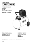
CRAFTS
AIR COMPRESSOR
20-gallon
1.5 HP
Oil-Free, Direct Drive
Model No. 921.166420
CAUTION"
Before using this product,
read this manual and follow
all its Safety Rules and
Operating Instructions.
Sears,
Roebuck
www.sears.com
11/14/2008
Part No. E103645
and Co., Hoffman
•
•
•
•
•
•
Safety Instructions
Installation & Operation
Maintenance & Storage
Troubleshooting
Guide
Parts List
Espa_ol, p. 11
Estates,
IL 60179
U.S.A.
Table of Contents
Page
Warranty ..............................................................
Safety Symbols
See Below
..........................................................
1
Important Safety Instructions & Guidelines .....................................
1
Specifications
2
............................................................
Glossary ................................................................
2
Duty Cycle ..............................................................
2
Parts & Features .........................................................
3
Installation & Assembly
4
Operating Procedures
....................................................
.....................................................
5
Maintenance .............................................................
6
Storage
6
................................................................
Troubleshooting
Guide .....................................................
7
Exploded View ...........................................................
8
Parts List ...............................................................
9
EspaSol ................................................................
11
ONE YEAR
FULL WARRANTY
ON CRAFTSMAN
AIR COMPRESSOR
If this Craftsman Air Compressor fails due to manufacturer's defects in material or workmanship
within one year of the date of purchase, RETURN IT TO THE NEAREST SEARS STORE OR
SERVICE CENTER IN THE UNITED STATES and it will be replaced or repaired (at our option),
free of charge.
If this Air Compressor is used for commercial or rental purposes, this warranty applies for only 90
days from the date of purchase. This warranty gives you specific legal rights and you may also
have other rights which vary from state to state.
Sears, Roebuck and Co., Hoffman Estates, IL 60179
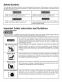
Safety Symbols
The information listed below should be read and understood by the operator. This information is given to protect the
user while operating and storing the air compressor. We utilize the symbols below to allow the reader to recognize important
information about their safety.
Indicates an imminently hazardous situation which, if not
avoided, will result in death or serious injury.
Indicates a potentially hazardous situation which, if not
avoided, may result in minor or moderate injury.
Indicates a potentially hazardous situation which, if not
avoided, could result in death or serious injury
When used without the safety alert symbol indicates a
potentially hazardous situation which, if not avoided, may
result in property damage.
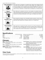
Important Safety Instructions and Guidelines
• Save all instructions
Improper operation or maintenance of this product could result in serious injury and/or property damage.
understand all of the warnings and safety instructions provided before using this equipment.
The air compressor should be operated on a dedicated 15 amp circuit. If the circuit does
not have 15 free amps available, a larger circuit must be used. Always use more air
hose before utilizing extension cords. All extension cords used must be 12 gauge with a
maximum length of 25 ft. The circuit fuse type must be a time delay. Low voltage could
cause damage to the motor.
[o llj o)
Risk of Moving
Read and
Parts
If the air compressor is in operation, all guards and covers should be attached or
installed correctly. If any guard or cover has been damaged, do not operate the
equipment until the proper personnel has correctly repaired the equipment. The power
cord should be free of any moving parts, twisting and/or crimping while in use and while
in storage.
Risk of Burns
There are surfaces on your air compressor that while in operation and thereafter can
cause serious burns if touched. The equipment should be allowed time to cool before
any maintenance is attempted. Items such as the compressor pump and the outlet tube
are normally hot during and after operation.
Risk of Falling
Operation of the air compressor should always be in a position that is stable. Never use
the air compressor on a rooftop or elevated position that could allow the unit to fall or
be tipped over. Use additional air hose for elevated jobs.
Risk from Flying Objects
Always wear ANSI Z87.1 approved safety glasses with side shields when the air
compressor is in use. Turn off the air compressor and drain the air tank before
performing any type of maintenance or disassembly of the hoses or fittings. Never point
any nozzle or sprayer toward any part of the body or at other people or animals.
Important Safety Instructions & Guidelines
Risk of Breathing
Avoid using the air compressor in confined areas. Always have adequate space
(12 inches) on all sides of the air compressor. Also keep children, pets, and others out of
the area of operation. This air compressor does not provide breathable air for anyone or
any auxiliary breathing device. Spraying material will always need to be in another area
away from the air compressor to not allow intake air to damage the air compressor filter.
Risk of
Electrical Shock
Never utilize the air compressor in the rain or wet conditions. Any electrical issues or
repairs should be performed by authorized personnel such as an electrician and should
comply with all national and local electrical codes. The air compressor should also have
the proper three prong grounding plug, correct voltage, and adequate fuse protection.
Risk of
Explosion or Fire
Never operate the compressor near combustible materials, gasoline or solvent vapors.
If spraying flammable materials, locate the air compressor at least 20 feet away from the
spray area. Never operate the air compressor indoors or in a confined area.
Risk of Bursting
Always drain the air compressor tank daily or after each use. If the tank develops a leak,
then replace the air compressor. Never use the air compressor after a leak has been
found or try to make any modifications to the tank. Never modify the air compressor's
factory settings which control the tank pressure or any other function.
Specifications
Pump .........................
Motor ....................................
Bore ......................................
Stroke .....................................
Oil-Free Direct Drive
1.5 HP
2.28"
0.87"
Voltage Single Phase ......................
120 VAC
Minimum Circuit Requirement ..............
Air Tank Capacity ........................
Cut-in Pressure ...........................
Cut-out Pressure ..........................
SCFM @ 90 PSI ...............................
SCFM @ 40 PSI ...............................
15.0 Amps
20 Gallons
120 PSI
150 PSI
3.8
5.1
Glossary
CFM:
Cubic feet per minute.
SCFM: Standard cubic feet per minute; a unit of measure
for air delivery.
PSIG: Pounds per square inch gauge; a unit of measure
for pressure.
ASME: American Society of Mechanical Engineers.
California Code: Unit may comply with California Code
462 (I) (2)/(M) (2).
Cut-In Pressure: The air compressor will automatically
start to refill the tank when the pressure drops
below the prescribed minimum.
Cut-Out Pressure: The point at which the motor stops
when the tank has reached maximum air
pressure.
Code Certification: Products that bear one or more of
the following marks: UL, ULc, ETL, CSA, have
been evaluated by OSHA-certified independent
safety laboratories and meet the applicable
Underwriters Laboratories Standards for Safety.
Duty Cycle
This is a 50% duty cycle air compressor.
could damage the air compressor.
Do not run the air compressor more than 30 minutes of one hour. Doing so
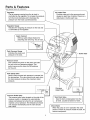
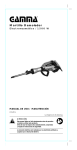
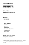
Parts & Features
See figures below for reference
I
Regulator
_
_ Air intake Filter
The air pressure coming from the air tank is
|
controlled by the regulator. To increase the pressure I
turn the knob clockwise and to decrease the
|
|
|
[
pressure turn the knob counterclockwise.
"-
Provides clean air to the pump and must
|
always be kept free of debris. Check on a |
daily basis or before each use.
J
J
Quick Connect
Offers a quick release feature for
attaching and removing the air hose.
I Tank Pressure Gauge
_
Indicates the reserve air |
pressure in the tank.
Outlet Tube
J
Pressure Switch
This controls the power to the motor and also
the cut-in/cut-out
pressure settings. This
switch serves as the Auto-On/Off positions
for the unit.
Tank Safety Valve
Used to allow excess tank pressure to escape into
the atmosphere. This valve should only open when
the tank pressure is above the maximum rated
pressure.
L.
Pressure Relief Valve
The pressure relief valve located on the side of the
pressure switch, is designed to automatically
release compressed air when the air compressor
reaches cut-out pressure. The released air should
only escape momentarily and the valve should
then close.
I Tank Drain Valve
I
J
Used to drain condensation
from the
air tank.
of tank.
Check Valve
Located
at bottom
_
"_
When the pump is not in operation the valve
|
closes to retain air pressure inside the tank. An|
internal component.
Installation & Assembly
The air compressor should be turned off, unplugged from
the power source, the air bled from the tank and the unit
allowed time to cool before any maintenance is performed.
Personal injuries could occur from moving parts, electrical
sources, compressed air or hot surfaces. The quick connect
assembly must be attached before use. Failure to assemble
correctly could result in leaks and possible injury. If unsure
of assembly instructions or you experience difficulty in the
assembly please call your local service department for
further information.
Improper installation of the grounding plug will result in a
risk of electric shock. If repair or replacement of the cord
or plug is necessary, do not connect the grounding wire to
either flat blade terminal. The wire with insulation having an
outer surface that is green with or without yellow stripes is
the grounding wire. Check with a qualified electrician or
serviceman if the grounding instructions are not completely
understood, or if in doubt as to whether the product is
properly grounded. Do not modify the plug provided.
If it will not fit the outlet, have the proper outlet installed
by a qualified electrician.
Getting Started - Location of the Air Compressor
The air compressor should always be located in a clean,
dry and well ventilated environment. The unit should have
at minimum, 12 inches of space on each side. The air filter
intake should be free of any debris or obstructions.
Check the air filter on a daily basis to make sure it is clean
and in working order.
This product is for use on a circuit having a nominal rating
of 120 volts and is factory-equipped with a specific electric
cord and plug to permit connection to a proper electric
circuit. Make sure the product is connected to an outlet
having the same configuration as the plug. An adapter
should not be used with this product. If the product must
be reconnected for use on a different type of electric circuit,
qualified service personnel should make the reconnection.
Risk Of Fire Or Explosion
This product incorporates snap action switch contacts and
a universal electric motor which tend to produce arcs and
sparking and therefore should not be exposed to flammable
liquids or vapors. This product is not intended for installation
or use in a commercial garage or shop environment.
Extension Cords
Use only a 3-wire extension cord that has a 3-blade
grounding plug and a 3-slot receptacle that will accept the
plug on the product. Make sure your extension cord is in
good condition. When using an extension cord, be sure to
use one heavy enough to carry the current your product will
draw. Cords must not exceed 25 feet and No. 12 AWG size
must be used. An undersized cord will cause a drop in line
voltage resulting in loss of power and overheating.
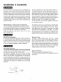
Grounding Instructions
This product should be grounded. In the event of an electrical
short circuit, grounding reduces the risk of electric shock by
providing an escape wire for the electric current.
This product is equipped with a cord having a grounding
wire with an appropriate grounding plug. (See the figure
below.) The plug must be plugged into an outlet that is
properly installed and grounded in accordance with all local
codes and ordinances. Check with a qualified electrician or
service personnel if these instructions are not completely
understood or if in doubt as to whether the tool is properly
grounded.
Grounded
Outlet
j J-
Grounding
Pin
Break In Procedures
No break in procedure is required by the user.
This product is factory tested to ensure proper operation and
performance.
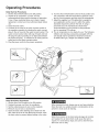
Operating Procedures
DaiJy Start=Up Procedures
1. Set the Auto-On/Off switch to the Off position.
2. Inspect the air compressor, air hose, and any
accessories/tools being used for damage or obstruction.
If any of these mentioned items are in need of repair/
replacement, contact your local authorized dealer before
use.
3. Close the drain valve.
4. Connect the air hose to the quick connect socket on
the regulator assembly by inserting the quick connect
plug on the air hose into the quick connect socket. The
quick connect socket collar will snap forward and lock
the plug into place providing an air tight seal between
the socket and plug. To release the air hose push the
collar back on the quick connect socket.
5. Plug the power cord into the proper receptacle.
6. Turn the Auto-On/Off switch to the On-Auto position and
the compressor will start and build air pressure in the
tank to cut-out pressure and then shut off automatically.
7. Adjust the regulator to a PSi setting that is needed for
your application and be sure it is within the safety
standards required to perform the task. If using a
pneumatic tool, the manufacturer should have
recommendations in the manual for that particular
tool on operating PSi settings.
8. The air compressor is now ready for use. The following
inflation and cleaning accessories packaged with this
unit should only be operated at maximum pressure
of 90PSI: Blow gun, adapter and inflation needle.
®
®
DaiJy Shut=Down Procedures
1. Set the Auto-On/Off switch to the Off position.
2. Unplug the power cord from the receptacle.
3. Set the outlet pressure to zero on the regulator.
4. Remove any air tools or accessories.
5. Open the drain valve allowing air to bleed from the
tank. After all of the air has bled from the tank, close
the drain valve to prevent debris buildup in the valve.
When draining the tank, always use ear and eye protection.
Drain the tank in a suitable location; condensation will be
present in most cases of draining.
Water that remains in the tank during storage will corrode
and weaken the air tank which could cause the tank to
rupture. To avoid serious injury, be sure to drain the tank
after each use or daily.
Maintenance
NOTE: Any service procedure
not covered
in the
maintenance schedule should be performed by qualified
service personnel.
The air compressor should be turned off, unplugged from
the power source, air bled from the tank and allowed
time to cool before any maintenance is performed.
Items to Check/Change
Before each use
or daily
Check Tank Safety Valve
X
Overall Unit Visual Check
X
Drain Tank
X
Check Power Cord for Damage
X
Do not attempt to remove or adjust the safety valve.
Check the safety valve by performing these three steps:
1. Plug the compressor in and run until shut-off pressure
is reached.
2. Wearing safety glasses, pull out on the safety valve ring
to release pressure from the tank.
3. The safety valve should close automatically
at
approximately at 40-50 PSI. If the safety valve does not
allow air to be released when you pull out on the ring, or
does not close automatically, it must be replaced.
To ensure efficient operation and longer life of the air
compressor unit, a routine maintenance schedule should
be followed. The following schedule is geared toward a
consumer whose compressor is used in a normal working
environment on a daily basis.
This compressor is equipped with an automatic reset
thermal overload protector which will shut off motor if it
becomes overheated. If the thermal overload protector is
actuated, the motor must be allowed to cool down before
start-up is possible.
NOTE: The motor will automatically restart without warning if the unit is left plugged in to an outlet with the AutoOn/Off switch in the on position
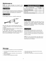
Storage
For storing the air compressor, be sure to do the following:
1. Turn the unit off and unplug the power cord from the
receptacle.
2. Remove all air hoses, accessories, and air tools from
the air compressor.
3. Perform the daily maintenance schedule.
4. Open the drain valve to bleed all air from the tank.
5. Close the drain valve.
6. Store the air compressor in a clean and dry location.
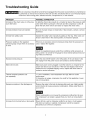
Troubleshooting
Guide
The air compressor should be turned off and unplugged from the power source before any maintenance
is performed as well as the air bled from the tank and the unit allowed time to cool. Personal injuries
could occur from moving parts, electrical sources, compressed air, or hot surfaces.
PROBLEM
POSSIBLE CORRECTION
Air leaks at the check valve or at the pressure relief valve.
A defective check valve results in a constant air leak at the pressure relief
valve when there is pressure in the tank and the compressor is shut off.
Drain the tank, then remove and clean or replace the check valve.
Air leaks between head and cylinder.
Be sure of proper torque on head bolts. If leak remains, contact a service
technician.
Air leak from safety valve.
Operate the safety valve manually by pulling on the ring. If the valve continues to leak when in the closed position, it should be replaced.
Pressure reading on the regulated
pressure gauge drops when an accessory
is used.
If there is an excessive amount of pressure drop when the accessory is
used, replace the regulator.
Adjust the regulated pressure under flow conditions (while accessory is
being used). It is normal for the gauge to show minimal pressure loss during initial use of the tool.
Excessive tank pressure.
Move the Auto-On/Off switch to the Off position. If the unit doesn't shut
off, unplug it from the power source and contact a service technician.
Motor will not start.
Make sure power cord is plugged in and the switch is on. Inspect for the
proper size fuse in your circuit box. If the fuse was tripped, reset it and
restart the unit. If repeated tripping occurs, replace the check valve or
contact a service technician.
Thermal overload protector cuts
out repeatedly.
1. Lack of ventilation, room temperature too high. Move to cooler
environment.
2. Excessive air usage, compressor too small for this application. Lower
rate of consumption.
Excessive moisture in the discharge air.
Remove the water in the tank by draining after each use. High humidity
environments will cause excessive condensation. Utilize water filters on
your air line.
Water condensation is not caused by compressor malfunction. Be sure
the compressor's air output is greater than your tool's air consumption
rate.
Air leaks from the tank body or tank welds.
Never drill into, weld or otherwise modify the air tank or it will weaken.
The tank can rupture or explode. Compressor cannot be repaired.
Discontinue use of the air compressor.
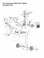
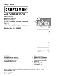
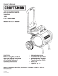
Air Compressor
Exploded View
36
37
38
39
41
42
43
47
48
49
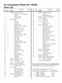
Model 921.166420
Air Compressor
Parts List
Ref.
No.
Kit
No.
1
2
3
4
5
6
7
8
9
10
11
12
13
14
15
16
17
18
19
20
21
22
23
24
25
26
27
28
29
30
31
32
33
34
35
36
37
38
39
4O
41
42
43
44
45
1
1
1
1
1
Pad
Number
Model 921.166420
Description
E100296 Shroud,F2, Full, Front
Screw,M5x 0.8 x 15ram,Left Hand
Threads
1
Washer,Lock,M5
Washer,Flat, M5
E100297 Fan, F2
Piston
1
1
1
1
Ring, Piston
Cap, Piston
Washer,Flat, M5
Screw,M5x 0.8 x 16ram,SHCS
Bearing,C & U
Screw,M6x 1 x 35, SHCS
1
2
2
2
2
2
2
2
2
2
3
3
3
Quantity
Motor,Oil Free,1.5 hp
Cylinder,Steel,Coated
O-Ring,Cylinder
Screw,M3x 0.4 x 5ram, HFHS
Retainer,InletValve
Valve, Intake
Plate, Valve
Valve,Outlet
Retainer,OutletValve
Screw,M3x 0.4 x 5ram, HFHS
O-Ring,Head
Air Filter,Cap
Air Filter,Element
Air Filter,Base
Washer,Lock,M6
Screw,M6x 1 x 35, SHCS
Head, F2
Elbow,90 degree,
13ramflarex 13/16npt
StrainRelief
PowerCord
E100300 Shroud,F2, Full, Rear
E101076 Cover,Motor
Screw,M6x 1 x 12, HFHS
E100307 Coupler,QuickConnect
E102758 Gauge,2", 150 psi Red Line,
250 psi, Back Inlet
E102196 Knob
Screw,M4x 0.8 x 10
Screw,M4x 10, SEMS
Plate,Control Panel
Nut,Compression,11/16
E103621 Tube,Outlet,Copper
Nut,Compression,3/8
Ferrule,3/8
1
1
1
1
1
1
1
1
1
1
1
1
1
1
1
1
1
1
1
1
1
4
4
1
Ref.
No.
46
47
48
49
50
51
52
53
54
55
56
57
58
59
6O
61
62
63
64
65
66
67
68
69
70
71
72
73
74
75
1
1
1
1
76
77
78
1
6
79
1
1
2
4
1
1
1
1
1
Kit
No.
Part
Number
Description
Quantity
E103622 Tube, Relief,Aluminum
Ferrule,1/4
Nut,Compression,1/4
E101362 Valve, Check,90 degree,Left
E103625 Handle
Tank,ASME
E101717 Drain,1/4 Turn
Nut,M6 x 1
Washer,Flat,M6
E101037 Isolator,Sears
Screw,M6 x 1 x 20, SHCS
Nut,Lock,MIO x 1.25
Wheel,Sears,8 in
Washer,Flat,MIO
Bolt, MIO x 1.25x 35ram,HH
Hubcap,Sears,Black
Screw,Set, M6
Screw,M6 x 1 x 16ram,SHCS
Washer,Lock,M6
Washer,Flat,M6
Screw,M5 x 0.8 x 25ram,SHCS
Nut,M5 x 0.8
Eccentric
Screw,M8 x 1.25x 16ram,SHCS
Washer,Lock,M8
Washer,Flat,M8
Nut,M8 x 1.25
E102159 Grip, Foam Rubber
E103623 Hose,Manifold
Elbow,90 degree,
1/4in mnpt x 1/4in fnpt
E101952 Manifold,Sears
E102750 Switch, Pressure,150cut out
E102746 Gauge,2", 150 psi Red Line,
250 psi, 3-oclockinlet
E102612 Valve, Safety,165 psi
1
2
2
1
1
1
1
2
2
2
2
2
2
2
2
2
4
2
2
2
1
1
1
4
4
4
4
1
1
2
1
1
1
1
Note:Anypart/kitnumberfieldwithouta numberis notavailable.Descriptions
areprovided
forreference
only. TheKit# columnrepresents
thatthepartbeing
offeredis available
in a kit.Oneof eachpartperkit willbeoffered.
Kit numberand partsthat are includedare as follows:
Kit No. Part No.
Description
ReferenceNo.
1
2
3
4
E103495
E103497
E100794
E102369
PistonKit
Valve PlatKit
Air Filter Kit
Wheel Kit(only one wheel)
6-10,14
15-23
24-26
58, 61
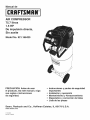
Manual
de
CRRFT3MRIi®
AiR COMPRESSOR
75.7 iitros
1.5 HP
De impulsi6n directa,
Sin aceite
Model No. 921.166420
PRECAUCi6N: Antes de usar
el producto, lea este manual y siga
sus reglas e instrucciones
de seguridad.
Sears, Roebuck
www.seaFs.coi33
11/14/2008
Part No. E103645
and Co., Hoffman
= Instrucciones y pautas de seguridad
importantes
= Instalaci6n y operacibn
= Mantenimiento y Almacenamiento
= Diagnostico y correcci6n de fallas
= Lista de las piezas
Estates,
IL 60179 U.S.A.
Contenido
Pagina
Garantia
estap_,gina
Simbolosde seguridad........................................................
13
Important Safety Instructions & Guidelines .....................................
13
Especificaciones............................................................
14
Glosario ................................................................
14
Ciclo de trabajo.............................................................
14
Partesy caracteristicas........................................................
15
Instalaci6ny ensamblaje.......................................................
16
Procedimientosde operaci6n....................................................
17
Mantenirniento.............................................................
18
Alrnacenamiento............................................................
18
Diagn6sticoy correcci6nde fallas.................................................
19
Vista esquem_.tica
...........................................................
20
Lista de las piezas...........................................................
21
GARANTiA
COMPLETA
DURANTE
UN AI_IO DEL COMPRESOR
DE AIRE CRAFTSMAN
Si este compresor de aire Craftsman fallase debido a defectos en materiales y mano de obra
dentro de un aSo a partir de la fecha de compra, DEVOLVERLO AL ESTABLECIMIENTO 0
CENTRO DE SERVICIO SEARS MAS CERCANO EN LOS ESTADOS UNIDOS y este set&
reemplazado o reparado (a nuestra opci6n), gratuitamente.
Si este compresor de aire se utiliza para fines comerciales o de alquiler, esta garantia es v&lida
solo durante 90 dias a partir de la fecha de compra. Esta garantia brinda al comprador original
del producto derechos legales especificos; el comprador original tambien podria tenet otros
derechos, los cuales varian de un estado a otto.
Sears, Roebuck and Co., Hoffman Estates, IL 60179
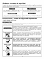
Simbolos comunes de seguridad
El operador debe leer y entender la informaci6n descrita a continuaci6n. Esta informaci6n se ofrece para proteger al
usuario al operar y almacenar el compresor de aire. Los simbolos siguientes son los que se utilizan para indicar al lector
informaci6n que es importante para su seguridad.
Indica una situaci6n de riesgo inminente que, al no
protegerse, provocar& lesiones graves o la muerte.
Indica una situaci6n potencialmente peligrosa que, de no
evitarse, podria provocar lesiones menores o moderadas.
Indica una situaci6n potencialmente peligrosa que, al no
protegerse, podrfa provocar lesiones graves o la muerte.
Cuando no aparezca sin el simbolo de alerta de seguridad, _sto
quiere decir que hay una situaci6n potencialmente peligrosa
que, al no protegerse, podria causar da_os materiales.
nstrucciones y pautas de seguridad importantes
• Guarde todas las instrucciones
La operaci6ny el mantenimientoinadecuadosde este productopuedenprovocarlesionesgravesy daSosmateriales.Antesde utilizareste equipo,
lea y entiendalas advertenciase instruccionesde seguridadaqui contenidas.
El compresor de aire se debe operar desde un circuito especial de 15 amperios.
Si el circuito no dispone de una capacidad de 15 amperios, se debe usar un circuito
de mayor capacidad. Si es necesario, antes de emplear una extensi6n el_ctrica, a_ada
una manguera de aire m_ts larga. Las extensiones el_ctricas deben ser de calibre 12
y tener una Iongitud maxima de 7,6 metros. El fusible del circuito debe ser de acci6n
retardada. Un voltaje demasiado bajo puede da_ar el motor.
Riesgo por partes en
movimiento
Riesgo de quemaduras
Riesgo
de caida
Riesgo de lanzamiento
de objetos
AI operar
el compresor, todos los protectores y cubiertas deben estar fijados e
instalados correctamente. Si alguno de los protectores o cubiertas esta dafiado, no
opere el equipo hasta que personal calificado repare el problema. El cable de corriente
debe mantenerse alejado de las partes m6viles del equipo y no debe torcerse ni
prensarse durante su empleo, ni al almacenarse.
En su compresor hay superficies que, al ser tocadas durante y despues de su
operaci6n, pueden causar quemaduras graves. Antes de darle mantenimiento al
equipo, se debe dejar enfriar. Por Io normal, durante y despues de su operaci6n,
ciertas partes como la bomba del compresor y el tubo de salida estar&n calientes.
El compresor siempre debe set operado en una posici6n estable. Nunca utilice el
compresor sobre un techo o en una posici6n elevada ya que podrfa caer o
volcarse. AI trabajar en posiciones elevadas, utilice una manguera de aire m&s larga.
AI emplear el compresor, siempre utilice anteojos de seguridad con protectores
laterales que cumplan con la norma ANSI Z87.1. Antes de Ilevar a cabo cualquier clase
de mantenimiento y antes de desconectar las mangueras y los acopladores, apague
el compresor y drene el tanque de aire. Nunca apunte la boquilla o el rociador hacia
ninguna parte de su cuerpo, ni el de otros seres.
13
Instrucciones y pautas de seguridad importantes
Riesgo para la
respiracibn
Evite utilizar el compresor de aire en Areas encerradas. Siempre tenga un espacio
libre adecuado (30 cm.) en todos los lados del compresor. Tambien mantenga fuera
del Area de operaci6n alas mascotas, ni_os y otras personas. Este compresor de aire
no provee aire que pueda set respirado ni empleado con un dispositivo respiratorio
auxiliar. El material de rociado siempre deberA estar en otra zona, alejado del compresor
de aire, para evitar que el aire aspirado daSe al filtro del compresor.
Riesgo de
descargas electricas
Nunca utilice el compresor de aire bajo Iluvia o en lugares mojados. Los problemas
electricos deben set reparados pot personal autorizado, tal como seria un electricista,
y deben cumplir con las normas electricas nacionales y locales. El compresor tambien
debe tenet la clavija apropiada de tres terminales para hacer tierra y contar con
un suministro electrico que sea del voltaje correcto y con un fusible de protecci6n
adecuado.
Riesgo de
explosibn y fuego
Nunca opere el compresor cerca de materiales combustibles, gasolina ni vapores
de solventes. Siesta rociando materiales inflamables, coloque el compresor a una
distancia de cuando menos 6 metros del Area de rociado. Nunca opere el compresor
de aire en interiores o en lugares cerrados.
Riesgo de estallido
Drene el compresor diariamente o despues de cada utilizaci6n. Si el tanque tiene una
fuga, reemplace el compresor. Nunca utilice el compresor si se ha detectado una fuga,
nitrate de modificar el tanque. Nunca modifique los ajustes de fAbrica del compresor
que controlan la presi6n del tanque y demAs funciones.
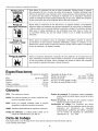
Especificaciones
Bomba .....................
Motor ...........................
DiAmetro ..................................
Carrera ...................................
Sin aceite, De impulsi6n
directa
Capacidad del tanque de aire ...............
75.7 litros
Presi6n de arranque .............
827.4 KPa / 120 PSI
Presi6n de parada ..............
1034.2 KPa / 150 PSI
Piescubicosper minuto(SCFM)a 90 LPPC.....................
3.8
Piescubicosper minuto(SCFM)a 40 LPPC.....................
5.1
1.5 HP (Universal)
58 mm
22 mm
Voltaje monofAsico ........................
Capacidad minima del circuito .................
120 VAC
15.0 A
Glosario
CFM:
Pies cQbicos por minuto.
Presi6n de arranque: El compresor arranca automAticamente cuando la presi6n baja a menos del minimo
prescrito.
Presi6n de parada: El motor se para cuando el tanque
alcance la presi6n maxima de aire.
Certificaci6n
de c6digo: Los productos que tienen
alguna o varias de las siguientes marcas han sido
evaluados
pot
laboratorios
de
seguridad
independientes certificados pot OSHA, y cumplen
con las normas de seguridad de Underwriters
Laboratories: UL, , ETL, CSA.
SCFM: Pies cQbicos estandar pot minuto; unidad de medici6n de suministro del aire.
PSIG:
Libras por pulgada cuadrada sobre la presi6n
atmosferica; unidad de medici6n de presi6n.
ASME: Sociedad estadounidense de ingenieros mecanicos.
C6digo de California: La unidad puede cumplir con el
c6digo de California 462 (I) (2)/(M) (2).
Ciclo de trabajo
Estecompresortiene un ciclo de trabajode 50%. Nuncaopereel compresorpor rnasde 30 minutoscadahora.
Ya que al hacerlo,podriada_arlo.
14
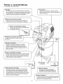
Partes y caracteristicas
Como referencia, vea las figuras abajo.
_ Regulador
/
l
|
"_
¢ Filtro
La presi6n del aire que sale del tanque es controlada
|
pot el regulador. Para aumentar
la presi6n, gire la periHa|
en direcciOn de las manecillas; para disminuirla, gire la |
|
|
|
del aire
"_
l
oI
Suministra aire limpio a la bomba. Siempre
debe conservarlo
Hmpio. Revfselo diariamente
antes de cada uso.
|
J
Conector de acoplarniento
r_pido
Permite conectar y desconectar rApidamente
la manguera del aire.
i
Man6rnetro
de presi6n
del tanque
"_
Indica la presi6n de la reserva de aire |
del tanque.
I
Tubo de
salida
J
lnterruptor
de presi6n
Controla el suministro el_ctrico en el motor y
tambi_n los ajustes de presi6n de arranque y
presi6n de parada. Este interruptor sirve como
posici6n de autoencendido
y apagado (Auto=On/
V&lvula de seguridad
del tanque
Permite que el exceso de presi6n en el tanque escape
hacia el medio ambiente. Esta vAIvula s61o se abrirA
cuando la presi6n en el tanque est6 pot encima de la
presi6n maxima nominal del modelo.
Tubo d alivio
de presi6n
I---_T-_
t_.
V&lvula de alivio de presi6n
Esta vAIvula, que se encuentra en el costado del
interruptor de presi6n, estA diseSada para liberar
aire comprimido de manera automAtica cuando el
compresor Ilegue a la presi6n de parada. El aire s61o
deberA escapar durante un instante, cerrAndose la
vAIvula se cerrarA en seguida.
I
V_lvula de drenaje
Sirve para drenar la condensaci6n
acumulada en el fondo del tanque. Se
"V&lvula de retenci6n
q
Cuando la bomba no estA en operaci6n, esta vAIvula
se cierra para retener la presi6n de aire dentro del |
tanque. Es un componente interno.
|
J
15
I
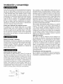
Instalacibn y ensamblaje
Antes de darle cualquier tipo de mantenimiento al compresor
de aire, se debe apagar y desconectar de la fuente de
alimentaciSn electrica, adem&s de purgar el aire del tanque
y darle suficiente tiempo para enfriarse. Existe el riesgo
de que las partes mSviles, las fuentes electricas, el aire
comprimido y las superficies calientes provoquen lesiones.
El ensamblaje de conexiSn r&pida debe estar instalado
antes de usar el compresor. Un ensamblaje inadecuado
puede ser causa de fugas y posiblemente de lesiones.
En caso de dudas sobre las instrucciones de montaje o
dificultad en el montaje, por favor Ilamar al departamento
de servicio local para mayor informaciSn.
Una conexiSn a tierra inadecuada puede provocar una
descarga electrica. Si necesita reparar o cambiar el cable o
la clavija, no conecte el alambre de tierra con ninguna de las
terminales planas. El alambre de tierra es de color verde,
con o sin franjas amarillas. Si no entiende completamente
las instrucciones de conexiSn a tierra, o si tiene dudas sobre
la correcta puesta a tierra de la herramienta, hable con un
electricista o agente de servicio calificado. No modifique la
clavija que viene con el equipo; si no puede enchufarla en
el tomacorriente, Ilame a un electricista calificado para que
le instale el tomacorriente adecuado.
Este producto esta dise_ado para trabajar en un circuito
con un voltaje nominal de 120 voltios y esta equipado en
la f&brica con un cable y clavija que permiten su conexiSn
a un circuito electrico apropiado. Aseg_rese de que el
producto este conectado a un tomacorriente con la misma
configuraciSn que la clavija. No se debe usar un adaptador
con este equipo. Si debe conectar el equipo con un circuito
electrico de diferente tipo, consiga la ayuda de personal
calificado para realizar la reconexiSn.
Cables de extensi6n
$51o utilice un cable de extensiSn de tres alambres con
una clavija con extensiSn a tierra de tres terminales que
pueda enchufarse en un tomacorriente de tres orificios.
Asegerese de que su cable de extensiSn est_ en buenas
condiciones. Si utiliza un cable de extensiSn, compruebe
que sea de la capacidad de la corriente que requiere su
equipo. Las extensiones no deben ser de m&s de 25 pies
(7,6 m) de largo y deben tener cable de calibre 12 AWG.
Un cable m&s delgado provocar& una ca{da en el voltaje
de la Imea, Io que provocaHa una perdida de potencia y
sobrecalentamiento.
Primer paso: Ubicaci6n del compresor del aire
El compresor del aire siempre debe estar en un medio
ambiente limpio, seco y bien ventilado. La unidad debe
tener por Io menos 30 cm de espacio libre en cada lado.
La toma del filtro del aire debe estar limpia y sin ning_n
tipo de obstrucciSn. Examinar el filtro de aire diariamente
para verificar que este limpio yen buenas condiciones de
funcionamiento.
Riesgo de incendio o explosi6n
Este producto incorpora un interruptor con contactos de
transiciSn brusca y un motor electrico universal que tienden
a producir arcos y chisporroteo. Por Io tanto, no se Io debe
exponer a Iiquidos o vapores inflamables.
Este producto
no esta previsto para uso o instalaciSn en un entorno de
garaje o taller comercial.
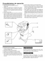
Procedimiento inicial de preparaci6n
No se requiere un procedimiento inicial de preparaciSn.
Este producto ha sido probado en la f&brica para asegurar
su operaciSn y rendimiento adecuados.
Instrucciones de conexi6n a tierra
Este producto se debe conectar a tierra. En el caso de
que haya un cortocircuito, la conexiSn a tierra reduce el
riesgo de descargas electricas al ofrecer una ruta de
escape para la corriente electrica. Este producto cuenta
con un cable que tiene un alambre de tierra y una clavija
con terminal de tierra (ver la figura a continuaciSn). La
clavija debe enchufarse en un tomacorriente instalado y
puesto a tierra segen las normas locales. Hable con un
electricista o agente de servicio calificado si no entiende
completamente
estas instrucciones,
o si tiene dudas
sobre la correcta puesta a tierra de la herramienta.
Grounded
Outlet
.JJ
Grounding
Pin
16
Procedirnientos de operaci6n
Procedimiento diario de arranque
1. Pongael interruptor
Auto-On/Offen la posici6nde
apagado(Off).
2. Verifiqueque el compresordel aire, la manguerade aire y todos los
accesoriosfherramientas
utilizados,no tenganda_osni obstrucci6n.
Encasode dudassobrelasinstrucciones
de montajeo dificultaden el
montaje,porfavorIlamaral departamento
de serviciolocalparamayor
informacBn.
3. Cierrela v_.lvulade drenaje.
4. Enchufela mangueradel aire dentrodel oonectorde aooplamiento
r_.pidode la unidaddel regulador,insertandola olavijade oonexi6n
r_.pidaen la mangueradel aire, dentrodel oonectorde aooplamiento
rapido.Ei oollarindel oonectorde aooplamientorapidosaltar_,haoia
adelante,sujetandola clavijay hara unajunta entreel ooneotory la
olavija. Paradesconeotarla mangueradel aire,empujehaoia atras
el oollarindel oonectorde aooplamientorapido.
5. Enchufeel cablede corrienteen un tomacorrienteapropiado.
6. Mueva el interruptor Auto-On/Off a la posioi6nde enoendido
(Auto-On); el oompresordebera arrancar,aoumulandola presi6n
del aire en el tanquehastaIlegara la presi6nde apagado,momento
en el oual se apagarade maneraautom_.tioa.
,
Ajustarel reguladora un valor de bar (psi) que sea necesariopara
el uso previstoy verifioarque est_ dentro de los estandaresde
seguridadrequeridos
pararealizarla tarea.Sise utilizaunaherramienta
neum_.tioa,
el fabricantedebe haberinoluidoen el manualde dioha
herramientavaloresrecomendados
parala presi6nde servioioen bar
(psi).
,
Ahorael compresorde aire est,. listo para uso. Los accesoriospara
infiadoy limpiezaque figurana continuaci6n,empacadoscon esta
unidad,se debenutilizara una presBnque no rebase6.2 bar(90 psi):
Pistolasopladora,adaptadory agujaparainfiado.
®
®
Procedimiento diario de apagado
1. Colocar ia palanca de encendido/apagado
la posici6n apagado (Off)
2. Desconecte el cable del tomacorriente.
(On/Off) en
Ai drenar ei tanque utiiice protecci6n para oidos y ojos.
Drene el tanque en un iugar apropiado; en ia mayoria de
ias ocasiones al drenar saldr_ condensaci6n.
3. Ponga en cero ei regulador de presi6n de salida.
4. Quite todas ias herramientas o accesorios de aire.
5. Abra la v_.lvula de drenaje permitiendo que escape el
aire dei tanque. Cuando haya salido del tanque todo el
aire, cierre ia vAIvuia de drenaje para evitar que entre
suciedad.
Si no drena el tanque al almacenario, en su interior
quedar_, agua que Io corroer_, y debiiitar_, io cual puede
provocar su ruptura. Para evitar iesiones graves, drene ei
tanque diariamente o despu_s de cada uso.
17
Mantenimiento
NOTA: Cualquier procedimiento de servicio que no
este cubierto en el programa de mantenimiento
que
sigue debera ser efectuado el personal de servicio
calificado.
Antes de dar mantenimiento
al equipo, se debe apagar
y desconectar
del tomacorriente,
asi como purgar el
aire del tanque y permitir que la unidad se enfrie.
Asuntos para verificar/cambiar
Antes de cada uso
o diariamente
RevisarlavAIvuladeseguridad
deltanque
X
Revisarvisualrnenteel aspectogeneral
de la unidad
X
Drenarel tanque
X
Verificarque el cableel6ctricono est6
daSado
X
no intentar retirar o ajustar la valvula de seguridad
A fin de asegurar una operaci6n eficiente y una larga vida
del compresor, debe seguir un programa de mantenimiento
de rutina. El siguiente programa de mantenimiento esta
enfocado al consumidor cuyo compresor es usado en un
medio ambiente normal y diariamente.
Revisar la v&lvula de seguridad mediante la ejecuci6n de
los tres pasos siguientes:
1. Enchufar el compresor y hacerlo funcionar hasta que
alcance la presi6n de desconexi6n.
2. Con gafas de seguridad puestas, tirar del aro de la v&lvula de seguridad para aliviar la presi6n del tanque. Usar
la otra mano para desviar el aire o despojos expelidos a
alta velocidad para protegerse la cara.
3. La v&lvula de seguridad debe cerrarse autom&ticamente a una presi6n aproximada de 2.8 a 3.4 bar (40 a
50 psi). Si la v&lvula de seguridad no permite la salida
del aire al tirarse del aro, o no cierra autom&ticamente, es
preciso reemplazarla.
Este compresor es equipado con un autom&tico repone
protector t_rmico de sobrecarga que apagar& el motor si
Ilega a ser recalentado. Si el protector termico de sobrecarga es accionado, el motor debe ser permitido enfriarse
antes de puesta en marcha es posible.
La NOTA: El motor reiniciar& autom&ticamente sin la advertencia si la unidad es dejada conect6 a una salida con
el interruptor de en/de prendido
Almacenamiento
Para almacenar el compresor, asegt3rese de hacer Io siguiente:
1. Apague la unidad y desconecte el cable electrico del
tomacorriente.
2. Quite del compresor
herramientas de aire.
las mangueras,
accesorios
4. Abra la v&lvula de drenaje para drenar el aire del
tanque.
5. Cierre la v&lvula de drenaje.
6. Guarde el compresor en un lugar limpio y seco.
y
3. Lleve a cabo el programa de mantenimiento de rutina.
18
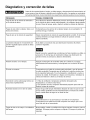
Diagnbstico y correccibn de fallas
Antes de dar mantenimiento al equipo, se debe apagar y desconectar del tomacorriente, as[
como purgar el aire del tanque y permitir que la unidad se enfrie. Las partes en movimiento,
las fuentes electricas, el aire comprimido y las superficies calientes pueden provocar lesiones.
PROBLEMA
POSIBLE CORRECCION
Fuga de aire en la v_lvula de retenci6n o
en la v_lvula de alivio.
Una v&lvula de retenci6n defectuosa provoca una fuga de aire constante
en la v&lvula de alivio cuando est_ apagado y el compresor tenga presi6n
de aire. Drene el tanque, quite y limpie o cambie la v&lvula de retenci6n.
Fugas de aire entre la cabeza Ilame a un
tecnico de servicio.
Compruebe que los pernos de la cabeza tengan un par apropiado. Si
continQa la fuga, el cilindro.
Fuga de aire en la vAIvula de seguridad.
Opere manualmente la v&lvula de seguridad jalando el anillo. Si el tanque
continQa teniendo una fuga estando la vAIvula en posici6n cerrada,
deber& cambiarla.
La presi6n indicada en el man6metro de
presi6n regulada bajarA cuando se utiliza
un accesorio.
Sial utilizar un accesorio hay una disminuci6n excesiva de presi6n,
cambie el regulador.
Ajuste la presi6n regulada bajo condiciones de flujo (mientras se utiliza un
accesorio). Es normal que el man6metro indique una disminuci6n de
presi6n minima al comenzar a utilizar la herramienta.
Presi6n excesiva
en el tanque.
Apague el interruptor de encendido (Off). Si la unidad no se apaga,
desconectela del tomacorriente y comuniquese con un t_cnico de servicio.
El motor no arranca.
Compruebe que el cable de corriente este enchufado y que el interruptor este encendido Compruebe que el fusible de la caja de circuitos sea
de la capacidad adecuada. Si se ha disparado, restablezcalo y vuelva a
arrancar la unidad. Si el fusible se dispara con frecuencia, reemplace la
v&lvula de retenci6n o Ilame a un t_cnico de servicio
El protector contra sobrecarga t@mica se
desconecta repetidamente.
1. Falta de ventilaci6n, temperatura ambiente demasiado alta.
Desplazarlo a un entorno mas fresco.
2. Uso excesivo de aire; compresor demasiado pequefio para este uso.
Reducir la tasa de consumo.
Humedad excesiva en el aire de salida.
Saque el agua del tanque dren&ndolo despues de cada vez que se use.
En los medios ambientes de alta humedad habrA un exceso de condensaci6n; instale filtros de agua en su linea de aire.
La condensaci6n no es provocada por una falla en el compresor.
Compruebe que la salida de aire del compresor sea mayor que el consumo del aire de su herramienta.
Fugas de aire en el cuerpo o la soldadura
del tanque.
Nunca taladre, suelde o modifique de ninguna manera el tanque, pues se
debilitar&. El tanque podria romperse o explotar. El tanque no puede set
reparado.
19
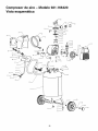
Compresor de aireVista esquem_tica
Modelo 921.166420
36
37
38
39
41
42
43
47
48
49
20
Compresor de aireLista de las piezas
# de
# de
referenca kit
1
2
3
4
5
6
7
8
9
10
11
12
13
14
15
16
17
18
19
2O
21
1
2
2
2
2
2
2
2
22
2
23
24
2
3
25
26
3
3
27
28
29
30
31
32
33
34
35
36
37
38
39
4O
41
42
43
44
45
46
47
1
1
1
1
1
# de
parte
Modelo 921.166420
descripci6nde parte
# de
# de
referencia kit
cant.
E100296 GuarderadelanteracornpletaF2
TornilloM5 x 0.8 x 15 ram,
roscasa izquierdas
Arandelade seguridadM5
Arandelaplana M5
E100297 VentiladorF2
Pist6n
1
48
49
1
1
1
1
1
Anillo del pist6n
Tapa del pist6n
Arandelaplana M5
TornilloM5 x 0.8 x 16 rnrn,SHCS
CojineteC y U
TornilloM6 x 1 x 35, SHCS
Motorsin aceite,1.5hp
Cilindrode acero recubierto
Anillo t6ricodel cilindro
TornilloM3 x 0.4 x 5 rnrn,HFHS
Retenedorde la v_.lvulade entrada
V_.lvulade entrada
Placade v_.lvula
V_.lvulade salida
Retenedorde la v_.lvulade salida
TornilloM3 x 0.4 x 5 rnrn,HFHS
Anillo t6ricode la cabeza
1
1
1
1
1
1
1
1
1
1
1
1
1
1
1
1
1
Tapa del filtro de aire
Elernentodel filtro de aire
Basedel filtro de aire
1
1
1
Arandelade seguridadM6
TornilloM6 x 1 x 35, SHCS
CabezaF2
4
4
1
Codode 90 grados,
abocinadode 13 rnrnx 13/16npt
Protectorcontrajalones
Cablede alirnentaci6n
1
1
1
Tuercade compresi6n,3/8
F@ula,3/8
E103622 Tubo de aliviode alurninio
F@ula,1A
descripci6nde parte
cant.
parte
Tuercade compresi6n,1A
E101362 V_.lvuladeretenci6n,90 grados,
izquierda
E103625 Mango
TanqueASME
E101717 Drenaje,1/4 de vuelta
Tuerca M6x 1
2
1
1
1
1
2
2
Arandelaplana M6
E101037 AisladorSears
2
2
TornilloM6 x 1 x 20, SHCS
2
Tuercade fijaci6nMIO x 1.25
2
RuedaSearsde 8 pulgadas
2
Arandelaplana MIO
2
PernoMIO x 1.25x 35 ram,HH
2
TapacuboSearsnegro
4
Tornillode ajuste M6
2
Tornillorn6 x 1 x 16 rnrn,SHCS
2
Arandelade seguridadM6
2
Arandelaplana M6
TornilloM5 x 0.8 x 25 rnrn,SHCS 1
Tuerca M5x 0.8
1
Exc6ntrica
1
TornilloM8 x 1.25x 16 ram,SHCS 4
Arandelade seguridadM8
4
Arandelaplana M8
4
Tuerca M8x 1.25
4
50
51
52
53
54
55
56
57
58
59
6O
61
62
63
64
65
66
67
68
69
7O
71
72
73
74
75
E102159
E103623
Ernpu_aduradegornaespurna
1
Mangueradelrnt_ltiple
1
Codode 90 grados,1/4de pulgada
rnnptx 1/4 de pulgadafnpt
2
E101952 Mt_ltipleSears
1
E102750 Interruptordepresi6n,
desconexi6na 150
1
76
77
78
E100300 GuarderatraseracornpletaF2
1
E101076 Cubiertadel motor
1
TornilloM6 x 1 x 12,HFHS
6
E100307 Acopladorde conexi6nr@ida
2
E102758 Man6rnetrode 2 pulgadas,linea roja
a 150 psi, 250 psi, entradatrasera 1
E102196 Pornorojo
1
TornilloM4 x 0.8 x 10
2
TornilloM4 x 10,SEMS
4
Placadel paneldel rnan6rnetro
1
Tuercade cornpresi6n,11/16
1
E1036212 Tubo de salidade cobre
1
# de
E102746
Calibrede 2 pulgadas,linea roja a
150 psi, 250 psi, entradaalas
3 en punto
1
E102612 V_.lvuladeseguridad,165psi
1
79
Nora:CualquiercampoparalosnOmeros/juegos
de piezasqueno tenganun
nOmero
espec[fico
depieza,indicaquenoest,,disponible.
Lasdescripciones
se
proveen
solamente
comoreferencias.
Lacolumnaconel nQmero
dejuegoindica
quelapiezaofrecidaest,,disponible
comopartede unjuego.Unadecadauna
delaspiezasest,,ofrecida.
LosnQmeros
de losjuegosy laspiezasqueestb,
n incluidossedescriben
a continuaci6n:
# de kit # departe descripci6n
departe
1
2
3
4
1
1
1
2
21
E103495
E103497
E103794
E102369
Juegode pist6n
Juegode placade v_.lvula
Juegode filtro de aire
Juegode rueda
(incluyes61ouna rueda)
# de referencia
6-10, 14
15-23
24-26
58, 61
Your Home
For repair - in your home - of all majorbrand appliances,
lawn andgardenequipment,or heatingandcoolingsystems,
no matter who made it, no matter who sold it!
For thereplacementparts, accessoriesand
owner'smanualsthat youneedto do-it-yourself.
For Sears professionalinstallationof homeappliances
and itemslike garage dooropenersandwater heaters.
1-800-4-MY-HOME
® (1-800-469-4663)
Callanytime,day or night(U.S.A.and Canada)
www.sears.com
www.sears.ca
Our Home
For repair of carry-in itemslike vacuums,lawnequipment,
and electronics,call or go on-linefor the locationof your nearest
Sears Parts & Repair Center.
1-800-488-1222
Callanytime,dayor night(U.S.A.only)
www.sears.com
Topurchasea protectionagreement(U.S.A.)
or maintenanceagreement(Canada)ona productserviced by Sears:
1-800-827-6655
(U.S,A,)
1-800-361-6665
Parapedirserviciodereparacion
a domicilio,y para ordenar piezas:
1-888-SU-HOGAR
(Canada)
AuCanadapourserviceenfran_ais:
1-800-LE-FOYER
®
(1-888-784-6427)
MB
(t-800-553-6937)
www, sears,ca
Sealrs
® RegisteredTrademark/TM Trademark/SMService Mark of Sears,RoebuckandCo,
® Marca Registrada/ TM Marca de F_ibrica/SMMarca de Servicio de Sears, Roebuckand Co.
acMarquede commerce/m Marquedeposeede Sears,RoebuckandCo,
@Sears Brands,LLC