1
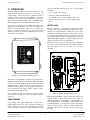
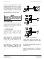
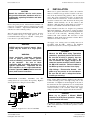
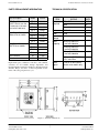
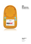
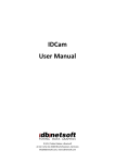
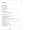
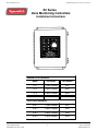
Release 02/2008 Ver. 2.0
Installation Instructions: ZC-Series Controllers
ZC Series
Zone Monitoring Controllers
Installation Instructions
MANUAL Reset Controllers
Model
Description
Part Number
ZC-1
1 Zone Controller
0421
ZC-2
2 Zone Controller
0422
ZC-3
3 Zone Controller
0423
ZC-4
4 Zone Controller
0424
AUTO Reset Controllers
TAPESWITCH CORPORATION
100 Schmitt Boulevard
Farmingdale, New York 11735
ZCA-1
1 Zone Controller
0431
ZCA-2
2 Zone Controller
0432
ZCA-3
3 Zone Controller
0433
ZCA-4
4 Zone Controller
0434
1
Phone: 631-630-0442
Fax: 631-630-0454
www.tapeswitch.com
Release 02/2008 Ver. 2.0
Installation Instructions: ZC-Series Controllers
CONTENTS
1. INTRODUCTION
Page
1. INTRODUCTION
2
2. PRINCIPLES
3
Tapeswitch ZC Series zone controllers are versatile, easy to
install electrical controls, made for industrial applications
and duty. They simplify the interfacing of conventional
sensing switches to industrial systems.
Tapeswitch
controllers feature:
ZONE SENSING
RESET LOGIC
OUTPUT CONTACTOR
3. APPLICATIONS
4
4. INSTALLATION
5
5. OPERATIONS
6
- Low voltage DC sensing circuits.
- One, Two, Three, or Four independent sensing zones
for monitoring multiple sensing switches.
- Continuous, independent zone monitoring; no
scanning.
- Multi-sensor interfacing - NO (Normally Open), NC
(Normally Closed), and supervised FAIL-SAFE
(four wire) sensing contacts can all be used.
- Individual zone indicators for easy troubleshooting.
- Hefty load contactor, up to 25 amps. Handles
industrial voltages, up to 600V AC.
- Single Phase or Three Phase load capability.
- A complete, pre-wired package, ready for use in a
heavy steel enclosure. National Electrical
Manufacturers Association (NEMA 12).
BASIC OPERATION
DAILY TESTING
SHUTDOWN
LOCKOUT OR TAGOUT
6. SERVICING
6
TROUBLESHOOTING
PARTS REPLACEMENT INFORMATION
TECHNICAL SPECIFICATION
Tapeswitch controllers are ideal for use with Tapeswitch
ControlMats, Armor Mats, Diamond Plate Mats, CVP style
Control Mats, Controflex ribbon switches, or Tapeswitch
sensing edges. These sensors are frequently in contact with
the ground, or are manually actuated. The controller
provides 24 Vdc for sensor operation, which is considered
non-hazardous in accordance with the National Electrical
Code (NEC), and there are no Radio Frequency
Interference (RFI) or capacitive coupling problems with
direct current.
WARNING:
AUTO Reset models are NOT to be used for
primary safety applications. See additional
cautions inside this manual.
Improper
application of an AUTO Reset controller may
result in death or serious injury to personnel.
TAPESWITCH CORPORATION
100 Schmitt Boulevard
Farmingdale, New York 11735
FAIL-SAFE supervision is an additional feature of
Tapeswitch zone controllers. When properly connected to
a FAIL-SAFE Switch, the load contactor will de-energize
on loss of power to the controller, activation of the sensor, a
short in the sensor or sensor wiring or a break (open) of the
sensor or sensor wiring.
2
Phone: 631-630-0442
Fax: 631-630-0454
www.tapeswitch.com
Release 02/2008 Ver. 2.0
Installation Instructions: ZC-Series Controllers
(and the controller will trip) upon any of the following
conditions:
2. PRINCIPLES
The basic function of these controllers is to turn off or on a
single powerful machine in response to low power, low
voltage inputs. One load circuit is controlled, based on
sensing switches connected to the different zone inputs.
Depending on the model selected, there may be one, two,
three, or four independent input zones. A ‘RESET’ input
will re-energize the machine after a fault is removed.
-
Two versions of each model are available, depending on the
application. In the Manual reset model, a specific reset
signal is needed to initiate output. In the AUTO reset
model, no signal is needed, and an output is initiated
whenever all zones are fault-free. Figure 1 shows a four
zone, manual reset model.
Loss of power to the controller
Activation of the switch in that zone
A short in the sensor or sensor wiring for that zone
A break (open) of the sensor or sensor wiring for that
zone
RESET LOGIC
The reset logic acts to energize and de-energize the output
contactor. The reset logic continuously checks zone status,
and the reset command signal. When all zones are clear
and fault-free, and the reset signal is received, the contactor
is energized. In a manual system, there must be a separate
reset signal, usually from the front panel push button. An
AUTO Reset Model requires no separate signal, and resets
whenever the zones are clear and fault-free.
Both the reset logic, and zone monitoring logic components
are located on the 'Zone PCB' inside the cabinet. Figure 2
shows the typical layout of the inside of a four zone
controller.
Figure 1 – Front Panel of manual reset ZC-4
All models of the ZC Series controllers are packaged in a
NEMA 12 wall-mount enclosure. Mounted internally on the
enclosure door is an LED circuit board which holds the
indicating lamps. In the main part of the enclosure, a
subpanel holds the main or 'zone' printed circuit board,
power transformer, and output contactor. Figure 2 shows
the internal arrangement of a ZC-4.
Zone controller operation is divided into three functions:
zone status monitoring, reset logic, and output contactor
operation.
Figure 2 - Internal Arrangement of a ZC-4
Because an AUTO Reset controller causes the output action
without further operator involvement, it is ideal for
machine automation. For example, a typical application
uses an industrial duty ControlMat to open a small door on
a reheating furnace. A worker carries a part to the furnace
using two handed tongs. The door opens automatically
when the worker steps on the mat. Operator safety is not
involved.
ZONE SENSING
Zone sensing takes place continuously. Each zone is
independently monitored by a low-voltage DC current loop
circuit. When the zone is clear and fault-free, the zone
status light is green. However, a red status light will show
TAPESWITCH CORPORATION
100 Schmitt Boulevard
Farmingdale, New York 11735
3
Phone: 631-630-0442
Fax: 631-630-0454
www.tapeswitch.com
Release 02/2008 Ver. 2.0
Installation Instructions: ZC-Series Controllers
When safety is involved, only the manual reset controller
should be used. Machine operation based on operator
presence-sensing is a dangerous application, forbidden by
OSHA in most instances. An example of a dangerous
AUTO Reset application would be a safety mat used in
front of an NC punch press. The mat only causes the press
to halt while the operator is on the mat. One worker was
injured when he stepped off a mat, onto the bed of a press
to clear a jam. When the jam cleared, the bed continued its
movement, pinning the worker. If the control had been
Manual Reset, the accident would not have occurred.
Figure 3- Connecting a Tapeswitch FAILSAFE sensor
WARNING:
Do not use an AUTO Reset control in a safety
application. Serious death or injury may result,
particularly during unexpected operations or
during maintenance.
OUTPUT CONTACTOR
Each ZC Series controller houses a small, high-power
contactor, suitable for switching machine loads up to about
1.5 HP. The output contactor is designed to handle a single
machine load. It is located on the lower left of the main
internal panel, as shown in Figure 2.
Figure 4 - Connecting an NO switch
3. APPLICATIONS
Section Two of this manual discusses the primary safety
considerations in selecting a Manual or Auto Reset
controller. Be sure you are familiar with the concepts
presented before applying a controller to a specific
machine.
The ZC Series controllers let you configure a sophisticated
array of sensors to control a single machine. When
multiple sensors are used, a frequent problem is the
difficulty in troubleshooting even a simple fault. Dividing
the sensors into zones and monitoring each zone
independently,
greatly
reduces
downtime
and
troubleshooting.
The ZC Series provides 1 to 4
independent zones. For custom systems with even more
zones, contact TAPESWITCH.
Figure 5 – Connecting an NC switch
Connecting multiple sensors on a single channel makes
troubleshooting more difficult and for that reason is NOT
recommended. TAPESWITCH recommends that no more
than two mat type sensors ever be used for a single zone.
Never bypass or disconnect a zone. Troubleshoot the
system by substituting components. If more, or fewer,
zones are needed, install a Tapeswitch controller with the
correct number of zones.
Each sensing zone may be connected in any of three
different wiring arrangements. A NO contact, a NC
contact, or a four wire FAIL-SAFE switch may be
connected to each zone. Figures 3, 4, and 5 show the
specific configuration to use when connecting each type of
sensor.
TAPESWITCH CORPORATION
100 Schmitt Boulevard
Farmingdale, New York 11735
All channels are configured for FAIL-SAFE operation as
shipped.
(User-supplied jumpers must be used to
reconfigure for other contact types). Note that the NO
connection is not supervised and should be avoided in some
applications.
4
Phone: 631-630-0442
Fax: 631-630-0454
www.tapeswitch.com
Release 02/2008 Ver. 2.0
Installation Instructions: ZC-Series Controllers
4.
CAUTION
INSTALLATION
When used to guard a hazardous location, the controller
must be a manual reset type, and be located in a safe area,
away from any hazards being guarded. This is common
sense. The operator should never be able to re-energize the
controls while in a hazard area. If the controller is best
located in a hazard area, then disconnect the front panel
“RESET” switch internally, cut off the connector, and
substitute a NO push button switch which is located in a
safe area. Use terminals 701 and 702 on the PC board.
Consult the technical data for each sensor
being used to determine maximum units in a
configuration, operating limitations and other
requirements.
Observe the polarity shown. This means that terminals 1 &
4 and 2 & 3 respectively must be connected to the same
continuous conductor. Tapeswitch FAIL-SAFE sensing
switches are coded to indicate polarity.
These industrial controllers are designed for permanent
hard-wired installation. They must be securely mounted.
(There are predetermined locations for mounting hardware
on the rear of the controller). Mounting brackets are
standard with each controller. The enclosure is rated
NEMA 12, which means dust and water resistant. This is
suitable for most indoor locations.
The load contactor has both NO and NC contacts. It can be
used to switch both legs of a single phase load. It is
recommended that both legs be switched. A three phase
load contactor is optionally available.
All supply, zone sensing, and load wiring must be in
accordance with the NEC.
Refer to the Technical
Specifications (Section 2) for data on permissible loads.
WARNING:
NEVER switch the electrical ground. Never
switch only the neutral on a single phase
load.
CAUTION:
Observe the NEC when wiring Tapeswitch
controllers, specifically Articles 300 and 310.
Be sure that all wiring is properly sized for
the load by referring to Table 310-17. Be
sure to connect the supply voltage to the
contactor common terminals and the load to
the NO or NC terminals. Failure to adhere to
the NEC may result in serious fire or injury.
WARNING:
Some particularly hazardous equipment,
such as power presses, require specific
levels of reliability, even when a fault occurs
to the controller.
Be sure to check
applicable ANSI and OSHA documents for
specific requirements. Tapeswitch ZC and
ZCA controllers are not single-fault-tolerant.
Contact Tapeswitch for information on multizone, multi-channel controllers.
High Voltage - Electrocution Hazard. Live
power may be present on the transformer.
Be sure that the unit is voltage-free before
installing or servicing.
TAPESWITCH ControlMats, ArmorMats, and other
sensing devices are color-coded to show polarity. Figure 6
shows typical color coding for a Control Mat.
Power (120 or 240 Vac) must be supplied to the controller.
Connect incoming power to the high voltage side of the
transformer. See Figure 2, and the diagram on the side of
the transformer. Power requirements are low, usually much
less than the 20 VA specified. If a 120 Vac load is to be
connected directly to the controller, insure that supply
wiring is properly sized to supply both load and controller.
CAUTION
Never try to convert a Manual RESET
controller to AUTO Reset operation. Damage
to the controller will result.
For 120 Vac operation, connect H1 to H3, and connect H2
to H4 on the transformer. For 240 Vac operation, connect
H2 to H3 only.
Figure 6 – Typical color code for ControlMats
TAPESWITCH CORPORATION
100 Schmitt Boulevard
Farmingdale, New York 11735
5
Phone: 631-630-0442
Fax: 631-630-0454
www.tapeswitch.com
Release 02/2008 Ver. 2.0
5.
Installation Instructions: ZC-Series Controllers
6.
OPERATIONS
SERVICING
TROUBLESHOOTING
CAUTION:
The following steps will usually isolate any problems in a
ZC Series zone controller system:
Be sure the controller has been properly
connected before attempting to operate the
unit.
- De-energize the load until the controller has
been checked out.
BASIC OPERATION
- Check that all wiring is secure and proper.
START UP: Turn on the power. The green power lamp
should light. All red indicator lamps should come on and
remain lit. This indicates that the zones have not been
‘RESET‘. (The AUTO reset version may switch from red
to green).
- Energize the controller only.
Check for
120/240 VAC to ‘HIGH VOLTAGE‘
terminals. Be sure connections are correct!
- Check that a lamp comes on in each zone when
power comes on. If none light, the power
transformer, or rectifier, may be defective, or
there may be loose internal wiring.
MANUAL RESET: Push the red ‘RESET‘ button. All
red and green lamps should come on and remain on until
the button is released. If any lamp does not come on, it
indicates a defective lamp or control channel. If the zone
switches are fault-free, the load contactor will energize with
a sound easily heard outside the cabinet.
- If only a few zones show lights at power on, it
indicates problems in the zones which show no
lamp. The controller’s logic board should be
replaced.
Release the red ‘RESET‘ button. The red lamps will go out
and the green lamps will remain on for all zones with faultfree sensing circuits. If any zone is not clear, its red lamp
will stay lit, and the load contactor will not energize.
- Manual reset only. If, at power on, all lamps
light and the load contactor energizes, it
indicates a short on the ‘RESET‘ lines, which
must be located and corrected! Operation with
a continuously closed ‘RESET‘ circuit will
damage the controller.
DAILY TESTING
Upon startup each day and prior to resetting the controller,
test the lamps, and test each zone by actuating the
appropriate sensing switch. On an AUTO reset model, do
not energize the load until the zones have been tested.
- Check the sensor wiring by pushing and
releasing the ‘RESET‘ button. The red lamps
should all go out, and the load contactors
should energize. If some zones will not reset,
check the sensors on these zones. If necessary,
disconnect sensor wires, and install a known
good FAIL-SAFE four wire switch. If the
zone still fails to ‘RESET‘, it indicates a
defective zone relay, which may be tested by
exchanging controller’s logic boards.
LAMP TEST: Press the red ‘RESET‘ button at any time
to test the lamps. All lamps should light. NOTE: This will
not affect the state of an energized load contactor. (For
auto reset, activate each zone separately to test).
SHUTDOWN
Simply turn off power to the Tapeswitch controller. The
load contactor will de-energize. The load contactor can
also be de-energized by activating one of the zone sensing
switches.
LOCKOUT OR TAGOUT
OSHA regulations (29CFR Part 1910.147). The control of
Hazardous Energy (lockout/tagout) final rule will be
enforced on or after January 2, 1990. This standard
requires employers to develop and utilize an energy control
program to prevent the unexpected energization or start up
of machines and equipment during service and maintenance
operation.
Formal employee training and written
documentation is required. There is no provision for
lockout at this controller.
TAPESWITCH CORPORATION
100 Schmitt Boulevard
Farmingdale, New York 11735
6
Phone: 631-630-0442
Fax: 631-630-0454
www.tapeswitch.com
Release 02/2008 Ver. 2.0
Installation Instructions: ZC-Series Controllers
PARTS REPLACEMENT INFORMATION
TECHNICAL SPECIFICATION
Part Description
LED Circuit Board
(AUTO Reset uses the
same part as the manual reset listed here)
ITEM
Power
Required
Zone Circuit Board,
Manual Reset models
Zone Circuit Board,
AUTO Reset models
Model
Part Nr.
ZC-1
13488
ZC-2
13489
ZC-3
13490
ZC-4
13491
Enclosure
NEMA 12
ZC-1
13473
Color
Beige
ZC-2
13463
24
ZC-3
13464
Sensor
Voltage
ZC-4
13462
Load
Capacity
10 Amp @ 600 VAC,
max non-inductive
ZCA-1
RATING
120 or 240
UNITS
VAC
50/60
Hz
20
VA
VDC
12 Amp @ 480 VAC,
mzx non-inductive
ZCA-2
ZCA-3
25 Amp @ 117 VAC,
max non-inductive
ZCA-4
Main contactor
All
11001
Transformer
All
11016
2 HP motor @ 120-600
VAC maximum
Reset
Signal
Replacement parts, additional controllers, and technical
assistance are all available through Tapeswitch, and
through industrial automation distributors throughout North
America, Europe, and Asia. Contact Tapeswitch for the
name of the sales group nearest to you.
NO to NC to NO contact,
manual reset models only
Figure 7 – ZC Series Dimensions
TAPESWITCH CORPORATION
100 Schmitt Boulevard
Farmingdale, New York 11735
7
Phone: 631-630-0442
Fax: 631-630-0454
www.tapeswitch.com