1
OC310A---1.qxp
06.7.7 3:48 PM
Page 1
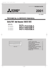
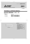
SPLIT-TYPE, HEAT PUMP AIR CONDITIONERS
July 2006
No. OC310
REVISED EDITION-A
TECHNICAL & SERVICE MANUAL
Series PKFY Wall Mounted
<Indoor unit>
[Model names]
R410A
R407C
[Service Ref.]
PKFY-P32VGM-E
PKFY-P40VGM-E
PKFY-P50VGM-E
PKFY-P32VGM-E
PKFY-P40VGM-E
PKFY-P50VGM-E
R22
Revision:
• RoHS PARTS LIST is added.
• Some descriptions have
been modified.
• Please void OC310.
Note:
• This manual describes only
service data of the indoor
units.
• RoHS compliant products
have <G> mark on the spec
name plate.
• For servicing of RoHS compliant products, refer to the
RoHS Parts List.
CONTENTS
Indoor unit
1. SAFETY PRECAUTION ···························2
2. PART NAMES AND FUNCTIONS············6
3. SPECIFICATIONS ····································8
4. OUTLINES AND DIMENSIONS ·············10
5. WIRING DIAGRAM·································11
6. REFRIGERANT SYSTEM DIAGRAM····12
7. TROUBLE SHOOTING ··························13
8. DISASSEMBLY PROCEDURE ··············20
9. PARTS LIST ···········································23
10. RoHS PARTS LIST ································25
OC310A---1.qxp
1
06.7.7 3:48 PM
Page 2
SAFETY PRECAUTION
CAUTIONS RELATED TO NEW REFRIGERANT
Cautions for units utilizing refrigerant R407C
Do not use the existing refrigerant piping.
Use liquid refrigerant to seal the system.
The old refrigerant and lubricant in the existing piping
contains a large amount of chlorine which may cause the
lubricant deterioration of the new unit.
If gas refrigerant is used to seal the system, the composition
of the refrigerant in the cylinder will change and performance
may drop.
Use “low residual oil piping”
Do not use a refrigerant other than R407C.
If there is a large amount of residual oil (hydraulic oil, etc.)
inside the piping and joints, deterioration of the lubricant
will result.
If another refrigerant (R22, etc.) is used, the chlorine in the
refrigerant may cause the lubricant deterioration.
Store the piping to be used during installation
indoors with keep both ends sealed until just
before brazing.
(Store elbows and other joints in a plastic bag.)
If dust, dirt, or water enters the refrigerant cycle,
deterioration of the oil and compressor trouble may result.
Use a vacuum pump with a reverse flow check valve.
The vacuum pump oil may flow back into the refrigerant
cycle and cause the lubricant deterioration.
Ventilate the room if refrigerant leaks during
operation. If refrigerant comes into contact with
a flame, poisonous gases will be released.
Use ESTR , ETHER or HAB as the lubricant to
coat flares and flange connection parts.
If large amount of mineral oil enter, that can cause
deterioration of refrigerant oil etc.
[1] Cautions for service
·After recovering the all refrigerant in the unit, proceed to working.
·Do not release refrigerant in the air.
·After completing the repair service, recharge the cycle with the specified amount of
liquid refrigerant.
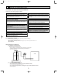
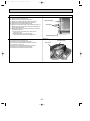
[2] Refrigerant recharging
(1) Refrigerant recharging process
1Direct charging from the cylinder.
·R407C cylinder are available on the market has a syphon pipe.
·Leave the syphon pipe cylinder standing and recharge it.
(By liquid refrigerant)
Unit
Gravimeter
(2) Recharge in refrigerant leakage case
·After recovering the all refrigerant in the unit, proceed to working.
·Do not release the refrigerant in the air.
·After completing the repair service, recharge the cycle with the specified amount of
liquid refrigerant.
2
OC310A---1.qxp
06.7.7 3:48 PM
Page 3
[3] Service tools
Use the below service tools as exclusive tools for R407C refrigerant.
No.
1
Tool name
Specifications
Gauge manifold
·Only for R407C.
·Use the existing fitting SPECIFICATIONS. (UNF7/16)
·Use high-tension side pressure of 3.43MPa·G or over.
2
Charge hose
3
Electronic scale
4
Gas leak detector
·Use the detector for R134a or R407C.
5
Adapter for reverse flow check.
·Attach on vacuum pump.
6
Refrigerant charge base.
7
Refrigerant cylinder.
·Only for R407C.
·Use pressure performance of 5.10MPa·G or over.
—
—
·For R407C
·Top of cylinder (Brown)
·Cylinder with syphon
8
Refrigerant recovery equipment.
—
3
OC310A---1.qxp
06.7.7 3:48 PM
Page 4
Cautions for units utilizing refrigerant R410A
Do not use the existing refrigerant piping.
Use a vacuum pump with a reverse flow check
valve.
The old refrigerant and lubricant in the existing piping
contains a large amount of chlorine which may cause the
lubricant deterioration of the new unit.
Vacuum pump oil may flow back into refrigerant cycle and
that can cause deterioration of refrigerant oil etc.
Use “low residual oil piping”
Use the following tools specifically designed for
use with R410A refrigerant.
The following tools are necessary to use R410A refrigerant.
If there is a large amount of residual oil (hydraulic oil, etc.)
inside the piping and joints, deterioration of the lubricant
will result.
Gauge manifold
Charge hose
Gas leak detector
Torque wrench
Store the piping to be used during installation
indoors and keep both ends of the piping sealed
until just before brazing. (Leave elbow joints, etc.
in their packaging.)
If dirt, dust or moisture enter into refrigerant cycle, that can
cause deterioration of refrigerant oil or malfunction of compressor.
Tools for R410A
Flare tool
Size adjustment gauge
Vacuum pump adaptor
Electronic refrigerant
charging scale
Keep the tools with care.
If dirt, dust or moisture enter into refrigerant cycle, that can
cause deterioration of refrigerant oil or malfunction of compressor.
Use ester oil, ether oil or alkylbenzene oil (small
amount) as the refrigerant oil applied to flares
and flange connections.
Do not use a charging cylinder.
If large amount of mineral oil enter, that can cause deterioration of refrigerant oil etc.
If a charging cylinder is used, the composition of refrigerant will change and the efficiency will be lowered.
Charge refrigerant from liquid phase of gas
cylinder.
If the refrigerant is charged from gas phase, composition
change may occur in refrigerant and the efficiency will be
lowered.
Ventilate the room if refrigerant leaks during
operation. If refrigerant comes into contact with
a flame, poisonous gases will be released.
Do not use refrigerant other than R410A.
If other refrigerant (R22 etc.) is used, chlorine in refrigerant can cause deterioration of refrigerant oil etc.
4
OC310A---1.qxp
06.7.7 3:48 PM
Page 5
[1] Cautions for service
(1) Perform service after collecting the refrigerant left in unit completely.
(2) Do not release refrigerant in the air.
(3) After completing service, charge the cycle with specified amount of refrigerant.
(4) When performing service, install a filter drier simultaneously.
Be sure to use a filter drier for new refrigerant.
[2] Additional refrigerant charge
When charging directly from cylinder
· Check that cylinder for R410A on the market is syphon type.
· Charging should be performed with the cylinder of syphon stood vertically. (Refrigerant is charged from liquid phase.)
Unit
Gravimeter
[3] Service tools
Use the below service tools as exclusive tools for R410A refrigerant.
No.
1
Specifications
Gauge manifold
·Only for R410A
·Use the existing fitting specifications. (UNF1/2)
·Use high-tension side pressure of 5.3MPa·G or over.
2
Charge hose
·Only for R410A
·Use pressure performance of 5.09MPa·G or over.
3
Electronic scale
4
Gas leak detector
·Use the detector for R134a, R407C or R410A.
5
Adaptor for reverse flow check
·Attach on vacuum pump.
6
Refrigerant charge base
7
Refrigerant cylinder
8
Refrigerant recovery equipment
·Only for R410A
Top of cylinder (Pink)
Cylinder with syphon
5
OC310A---1.qxp
2
06.7.7 3:48 PM
Page 6
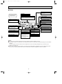
PART NAMES AND FUNCTIONS
● Indoor Unit
PKFY-P32VGM-E
PKFY-P40VGM-E
PKFY-P50VGM-E
Filter
Air intake grille
Air intake
Auto vane
Guide vane
Air outlet
● Wired remote controller
On the controls are set, the same operation mode can be repeated by simply pressing the ON/OFF button.
● Operation buttons
ON/OFF button
Set Temperature buttons
Down
Fan Speed button
Up
Timer Menu button
(Monitor/Set button)
Filter
button
(<Enter> button)
Mode button (Return button)
TEMP.
ON/OFF
Set Time buttons
Check button (Clear button)
Back
Ahead
Test Run button
MENU
BACK
MONITOR/SET
ON/OFF
FILTER
DAY
CHECK TEST
Airflow Up/Down button
Timer On/Off button
(Set Day button)
PAR-21MAA
OPERATION
CLOCK
CLEAR
Louver button
Operation button)
(
To preceding operation
number.
Opening the
door.
Ventilation button
Operation button)
(
To next operation number.
6
OC310A---1.qxp
06.7.7 3:48 PM
Page 7
● Display
“Sensor” indication
Displayed when the remote controller
sensor is used.
Day-of-Week
For purposes of this explanation,
all parts of the display are shown
as lit. During actual operation, only
the relevant items will be lit.
Shows the current day of the week.
Time/Timer Display
“Locked” indicator
Shows the current time, unless the simple or Auto Off
timer is set.
If the simple or Auto Off timer is set, shows the time
remaining.
Indicates that remote controller buttons have been locked.
Identifies the current operation
“Clean The Filter” indicator
Shows the operating mode, etc.
* Multilanguage display is supported.
Comes on when it is time to clean the
filter.
TIME SUN MON TUE WED THU FRI SAT
TIMER
Hr
ON
AFTER
FUNCTION
FILTER
˚F˚C
“Centrally Controlled” indicator
Indicates that operation of the remote controller has been prohibited by a master controller.
Timer indicators
AFTER OFF
ERROR CODE
˚F˚C
The indicator comes on if the corresponding timer is set.
WEEKLY
SIMPLE
AUTO OFF
ONLY1Hr.
Fan Speed indicator
Shows the selected fan speed.
“Timer Is Off” indicator
Indicates that the timer is off.
Temperature Setting
Shows the target temperature.
Up/Down Air Direction indicator
Room Temperature display
Shows the room temperature.
The indicator
shows the direction of the outcoming airflow.
Louver display
“One Hour Only” indicator
Indicates the action of the swing
louver. Does not appear if the
louver is stationary.
Displayed if the airflow is set to
weak and downward during COOL
or DRY mode. (Operation varies
according to model.)
The indicator goes off after one
hour, at which time the airflow direction also changes.
Ventilation indicator
Appears when the unit is running in
Ventilation mode.
(Power On indicator)
Indicates that the power is on.
Caution
● Only the Power on indicator lights when the unit is stopped and power supplied to the unit.
● If you press a button for a feature that is not installed at the indoor unit, the remote controller will display the “Not Available”
message.
If you are using the remote controller to drive multiple indoor units, this message will appear only if he feature is not
present at the parent unit.
● When power is turned ON for the first time, it is normal that “PLEASE WAIT” is displayed on the room temperature indication (For max. 2minutes). Please wait until this “PLEASE WAIT” indication disappear then start the operation.
7
OC310A---1.qxp
06.7.7 3:48 PM
3
Page 8
SPECIFICATIONS
3-1. SPECIFICATION
Item
PKFY-P40VGM-E
PKFY-P32VGM-E
PKFY-P50VGM-E
V•Hz
Cooling capacity
kW
3.6
4.5
5.6
Heating capacity
kW
4.0
5.0
6.3
Electric characteristic
Power
Single phase 220V-230V-240V · 50Hz / 220V · 60Hz
Cooling
kW
0.07
Heating
kW
0.07
Cooling
A
0.32
Heating
A
0.32
—
Plastic , white : <0.70Y 8.59/0.97>
Height
mm
340
Dimensions Width
mm
990
Depth
mm
235
—
Cross fin (Aluminum plate fin and copper tube)
Fan ✕ No
—
Linflow fan ✕ 1
Air flow W2
k/min
Input
Current
Exterior
(munsell symbol)
Heat exchanger
F
a
n
11.5-10.5-9.5-8
12-11-10-9
External
static pressure
Fan motor
output
Pa
0
kW
0.03
Insulator
—
Polyethylene sheet
Air filter
—
PP honey comb
Pipe
dimensions
Gas
side
Liquid
side
[mm(in.)
12.7(1/2")
12.7(1/2") / 15.88(5/8")
[mm(in.)
6.35(1/4")
6.35(1/4") / 9.52(3/8")
Unit drain pipe size
[mm
Noise level W2
dB
Product weight
kg
O.D.20 (PVC pipe VP-20 connectable)
41-38-36-33
43-40-37-34
16
Note 1. Rating conditions (JIS B 8615-1)
Cooling : Indoor D.B. 27°C W.B. 19°C
Outdoor D.B. 35°C
Heating : Indoor D.B. 20°C
Outdoor D.B. 7°C
W.B. 6°C
W2. Air flow and the noise level are indicated as High – Middium1 – Middium2 – Low .
8
OC310A---1.qxp
06.7.7 3:48 PM
Page 9
3-2. ELECTRICAL PARTS SPECIFICATIONS
Parts name
Model Symbol
PKFY-P32VGM-E
PKFY-P40VGM-E
PKFY-P50VGM-E
Room temperature thermistor TH21
Resistance 0°C/15kΩ, 10°C/9.6kΩ, 20°C/6.3kΩ, 25°C/5.4kΩ, 30°C/4.3kΩ, 40°C/3.0kΩ
Liquid pipe temperature thermistor TH22
Resistance 0°C/15kΩ, 10°C/9.6kΩ, 20°C/6.3kΩ, 25°C/5.4kΩ, 30°C/4.3kΩ, 40°C/3.0kΩ
Gas pipe temperature thermistor TH23
Resistance 0°C/15kΩ, 10°C/9.6kΩ, 20°C/6.3kΩ, 25°C/5.4kΩ, 30°C/4.3kΩ, 40°C/3.0kΩ
Fuse
(Indoor controller board)
FUSE
250V 6.3A
PM4V30-K 220-240V/220V , 50/60Hz
Fan motor
(with inner-thermostat)
4 pole Output 30W
MF
Inner-thermostat
OFF 125±5;
Fan motor capacitor
C1
2.0µF 440V
Vane motor
MV
MP 35 EA DC12V
Linear expansion valve
LEV
Power supply terminal block
TB2
(L, N, ;) 330V 30A
Transmission terminal block
TB5
(M1, M2, S) 250V 20A
DC12V Stepping motor drive
Port dimension [3.2 (0 ~ 2000pulse)
MA remote controller terminal block TB15
(1,2) 250V 10A
9
10
0
20
32
75
245
300
2
R5
405
.5
210
230
360
[90
50 w2
420
[75
495
32 , 40 , 50
[90 ~ [100
[75 ~ [80
Drain pipe (VP-20)
( Left side piping
35
installation )
310
322 w3
272
230
Gas pipe
Liquid pipe
W1 Sleeves are available on the market.
W2 In case of R22 or R407C.
W3 This size shows the lower end of through hole.
190
170
Through hole
150
Sleeve w1
425
Model
piping hole
0
right-rear piping
35
left-rear piping
205
Right-rear
260
Knock out hole for
190
32 , 40
Model
50
581
1/4F / 3/8F
1/4F
Liquid pipe
1/2F / 5/8F
1/2F
Gas pipe
700 ( Flexible hose total length 800 )
449
235
70
190
160
86
54
35
40
153
60
Service panel
(Power supply access)
Knock out hole for under piping
Refrigerant piping.Drain pipe.
Wiring hole
235
(Right side)
installation )
( Right side piping
31
Knock out hole for
345
320
R52.5
80
piping hole
135
190
395
225
233
280
Left-rear
95
R52.5
Filter grip
400
Auto vane
280 Air intake
60
130
35
55
80
0
50
990
705 Air outlet
12 - Louvers ( manual )
(Front view ( to open the grille ))
79
49 - [5 hole
for tapping screw
Less than 130
340
14 - [14 hole
for bolts
70
( Necessary clearance for Unit installation )
180 or more
balance point hole
Unit center
30 or more
Details of installation plate
150 or more
(Lower side)
80
715 Air intake
198 Air intake
Installation plate
21
Right side
53
50 or more
245
Address board
Knock out hole for right piping
Refrigerant pipe.Drain pipe.
Wiring hole
Less than 15
21 70
Front view
340 Air intake
245
Allowing clearances
60
(Front view)
PKFY-P32VGM-E
PKFY-P40VGM-E
PKFY-P50VGM-E
Knock out hole for left piping
Refrigerant pipe.Drain pipe.Wiring hole.
(Left side)
4
R5
2.
5
06.7.7 3:48 PM
495
OC310A---1.qxp
Page 10
OUTLINES AND DIMENSIONS
Unit : mm
OC310A---1.qxp
06.7.7 3:48 PM
5
Page 11
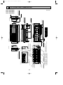
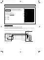
WIRING DIAGRAM
PKFY-P32VGM-E PKFY-P40VGM-E PKFY-P50VGM-E
Legend
Symbol
I.B
CN32
CN41
CN51
CN52
F.C
FUSE
SW2
SW3
SW4
X4
ZNR
Name
Indoor controller board
Connector Remote switch
HA terminal-A
Centrally control
Remote indication
Fan phase control
Fuse (6.3A)
Capacity code
Switch
Mode selection
Model selection
Aux.Relay (Fan motor)
Varistor
Symbol
C1
LEV
MF
MV
P.B
TB2
TB5
TB15
TH21
Name
Capacitor (fan motor)
Linear expansion valve
Fan motor (with inner thermo)
Vane motor
Indoor power board
Terminal Power supply
Transmission
block
Symbol
Name
TH23
Thermistor Pipe temperature detection/Gas
(0ºC/15k", 25ºC/5.4k")
A.B
Circuit board
SW1 Switch
Mode selection
SW5
Voltage selection
SW11
Address setting 1st digit
SW12
Address setting 2nd digit
Connection No.
SW14
MA-Remote Controller
Thermistor Room temperature detection
SWC
Option selector
(0ºC/15k", 25ºC/5.4k")
Pipe temperature detection/Liquid
TH22
(0ºC/15k", 25ºC/5.4k")
TO NEXT INDOOR UNIT
TB2
MF
3 2 1
AC220-240V
(RED)
TRANS
CNSK
FAN
(WHT)
CND
(RED)
BLK
WHT
BLU
RED
1 3 5
BREAKER
(15A)
(RED)
FUSE
250V
6.3A
X4
LED1
(WHT)
HA
CN41
ZNR
F.C
5
(RED)
ADDRESS
CN81
CN6V
8 7 6 5 4 3 2 1
BRN
RED
ORN
YLW
PIN
BLU
6 5 4 3 2 1
SW5
220V
240V
0
0
3RD
2ND
DIGIT DIGIT
0
1ST
DIGIT
4 3 2 1
0N
0FF
6 5 4 3 2 1
1
SW2
SW3
3
SW4
12345
1 2 3 4 5 6 1 2 3 4 5 6 7 8 9 10
(RED) (WHT) (BLK)
0N INTAKE LIQUID GAS
CN29
0FF CN20 CN21
2 1
2 1
2 1
LED2
BRN
RED
BLU
ORN
YLW
WHT
8
4
See fig:w1
(RED)
ADDRESS
CN43
SW1
ON
OFF
1 2 3 4 5 6 7 8 910
SW12 SW11
CN42
(WHT)
LEV
CN60
6
MV
A.B
(RED)
ADDRESS
1 5
(WHT)
DRAIN
CN31
CN2D 1
(WHT) 2
(BLU)
1 3 2 1 (M-NET) 1
CN2M 2
(WHT)
REMOTE
SWITCH
CN3A 1
CN32
(BLU) 2
1
3
4
(WHT)
(GRN)
REMOTE CENTRALLY
INDICATION CONTROL
CN51
CN52
X4
(GRN)
VANE
FUSE(15A)
2
1
1 3 CNDK
1 3
4
3
2
1
(RED)
ADDRESS
CN82
SWC
SW14
0
CONNECTION
NO.
8
7
6
5
4
3
2
1
TH21 TH22 TH23
LEV
<fig:w1>
Models
SW2
P32
ON
OFF
P40
ON
OFF
P50
ON
OFF
SW3
ON
OFF
123456
SW4
ON
OFF
1 2 3 4 5 6 7 8 910
ON
OFF
123456
12345
ON
OFF
1 2 3 4 5 6 7 8 910
123456
12345
ON
OFF
ON
OFF
1 2 3 4 5 6 7 8 910
12345
Note
1.At servicing for outdoor unit,always follow the wiring diagram of outdoor unit.
2.In case of using MA-Remote controller, please connect to TB15.
(Remote controller wire is non-polar.)
3.In case of using M-NET, please connect to TB5.
(Transmisson line is non-polar.)
4.Symbol[S] of TB5 is the shield wire connection.
5.Symbols used in wiring diagram above are, :terminal block,
:connecter.
6.The setting of the SW2 dip switches differs in the capacity for the detail,refer to the fig:w1.
7.Please set the switch SW5 according to the power supply voltage.
Set SW5 to 240V side when the power supply is 230 and 240 volts.
When the power supply is 220 volts,set SW5 to 220V side.
LED on indoor board for service
Mark
Meaning
Function
Main power supply(Indoor unit:220-240V)
LED1 Main power supply
power on ➞ lamp is lit
Power supply for
Power supply for MA-Remote controller
LED2 MA-Remote controller on ➞ lamp is lit
11
PULL BOX
DC13.1V
(WHT)
CN2S
3
2
1
RED
WHT
BLK
C1
I.B
L
N
POWER SUPPLY
~ 220-240V 50Hz
~ 220V 60Hz
BLK
WHT
BLU
BLU
ORN
TB5 S(SHIELD)
TO OUTDOOR UNIT
M2
BC CONTROLLER
M1
REMOTE CONTROLLER
DC24-30V
TB15
ORN
1
2
{
{
P.B
RED
BLU
GRN/YLW
TO MA-REMOTE
CONTROLLER
DC8.7-13V
OC310A---1.qxp
6
06.7.7 3:48 PM
Page 12
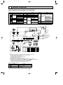
REFRIGERANT SYSTEM DIAGRAM
PKFY-P32VGM-E
PKFY-P40VGM-E
PKFY-P50VGM-E
Gas pipe temperature Strainer (#50mesh)
thermistor TH23
Gas pipe
Liquid pipe temperature
thermistor TH22
Flare connection
Liquid pipe
Heat exchanger
Linear expansion valve
Strainer (#100mesh)
Strainer (#100mesh)
Room temperature thermistor
TH21
Capacity
PKFY-P32VGM-E PKFY-P40VGM-E
PKFY-P50VGM-E
Gas pipe
{12.7 (1/2”)
{12.7 (1/2”) or [15.88(5/8”)
Liquid pipe
{6.35 (1/4”)
{6.35 (1/4”) or [9.52(3/8”)
Item
12
OC310A---1.qxp
06.7.7 3:48 PM
7
Page 13
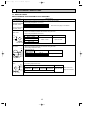
TROUBLE SHOOTING
7-1. HOW TO CHECK
PKFY-P32VGM-E PKFY-P40VGM-E PKFY-P50VGM-E
Check method
Parts name
Room temperature
thermistor (TH21)
Disconnect the connector then measure the resistance with the tester.
(Surrounding temperature 10°C~30°C)
Liquid pipe temperature
thermistor (TH22)
Normal
4.3k'~9.6k'
Abnormal
Open or short
Refer to the next page for the details.
Gas pipe temperature
thermistor (TH23)
Measure the resistance between the terminals using the tester.
(Surrounding temperature 20°C~30°C)
Vane motor
Orange
4
Red
5
M
Pink
2
3
6
1
Yellow Brown Blue
Fan motor
Connector
Brown - Yellow
Brown - Blue
Red - Orange
Red - Pink
Normal
Abnormal
186' ~ 214'
Open or short
Measure the resistance between the terminals using the tester.
(Surrounding temperature 20°C)
Fan
3
Red
1
2 White
1 Black
2
3
Motor terminal or
relay connector
Normal
Abnormal
Red - Black
White - Black
141.2Ω
131.5Ω
Open or short
Protector
Linear expansion
valve
1
4
Blue
M
6
Brown
5
2
3
Yellow
Disconnect the connector then measure the resistance with the tester.
(Surrounding temperature 20°C)
Normal
Abnormal
(1)-(5)
(2)-(6)
(3)-(5)
(4)-(6)
White-Red Yellow-Brown Orange-Red Blue-Brown
Open or short
150' ±10%
White Red Orange
13
Refer to the next
page for the details.
OC310A---1.qxp
06.7.7 3:48 PM
Page 14
<Thermistor Characteristic graph>
Thermistor for
lower temperature
< Thermistor for lower temperature >
50
Room temperature thermistor(TH21)
Liquid pipe temperature thermistor (TH22)
Gas pipe temperature thermistor (TH23)
40
Rt=15exp { 3480( 1
273+t
0:
10:
20:
25:
30:
40:
Resistance (K")
Thermistor R0=15k' ± 3%
Fixed number of B=3480K ± 2%
1 )}
273
15k'
9.6k'
6.3k'
5.4k'
4.3k'
3.0k'
30
20
10
0
-20
-10
0
10 20 30
Temperature (:)
40
50
Linear expansion valve
① Operation summary of the linear expansion valve.
• Linear expansion valve open/close through stepping motor after receiving the pulse signal from the indoor controller board.
• Valve position can be changed in proportion to the number of pulse signal.
<Connection between the indoor controller board and the linear expansion valve>
Controller board
DC12V
Brown
6
Red
5
[4
Blue
4
[4
[3
Orange
3
[3
[2
Yellow
2
[2
[1
White
1
[1
Linear expansion valve
4
M
6
5
2
1
White Red
3
Orange
Blue
Brown
Yellow
Connector(CN60)
14
Drive circuit
OC310A---1.qxp
06.7.7 3:48 PM
Page 15
<Output pulse signal and the valve operation>
Output
Output
(Phase)
1
2
3
4
{1
ON
OFF
OFF
ON
{2
ON
ON
OFF
OFF
{3
OFF
ON
ON
OFF
{4
OFF
OFF
ON
ON
Closing a valve : 1 → 2 → 3 → 4 → 1
Opening a valve : 4 → 3 → 2 → 1 → 4
The output pulse shifts in above order.
❈ 1. When linear expansion valve operation stops, all output phase
become OFF.
2. At phase interruption or when phase does not shift in order,
motor does not rotate smoothly and motor locks and vibrates.
➁ Linear expansion valve operation
C
D
Valve position (capacity)
❈ When the switch is turned on, 2200 pulse closing valve signal will
be send till it goes to A⁄ point in order to define the valve position.
Close
Open
2000 pulse
Opening a valve
all the way
A
E
When the valve move smoothly, there is no noise or vibration
occurring from the linear expansion valve : however, when the
pulse number moves from E⁄ to A⁄ or when the valve is locked,
more noise can be heard than normal situation.
❈ Noise can be detected by placing the ear against the screw driver handle while putting the screw driver to the linear expansion
valve.
Pulse number
B
Extra tightning (80~100pulse)
➂ Trouble shooting
Symptom
Check points
Operation circuit fail- Disconnect the connector on the controller board, then conure of the micro
nect LED for checking.
6
processor.
5
4
3
2
1
1T LED
Countermeasures
Exchange the indoor controller board at drive circuit
failure.
Pulse signal will be sent out for 10 seconds as soon as the
main switch is turned on. If there is LED with lights on or
lights off, it means the operation circuit is abnormal.
Linear expansion
valve mechanism is
locked.
Motor will idle and make ticking noise when motor is operated Exchange the linear
while the linear expansion valve is locked. This ticking sound expansion vale.
is the sign of the abnormality.
Short or breakage of Measure the resistance between the each coil (red-white,
the motor coil of the red-orange, brown-yellow, brown-blue) using a tester. It is
linear expansion
normal if the resistance is in the range of 150'+10%.
valve.
Exchange the linear
expansion valve.
Valve doesn't close To check the linear expansion valve, operate the indoor unit If large amount of thermiscompletely (thermis- in fan mode and at the same time operate other indoor units tor is leaked, exchange the
tor leaking).
in cooling mode, then check the pipe temperature <liquid
linear expansion valve.
pipe temperature> of the indoor unit by the
outdoor multi controller board operation
monitor. During fan operation, linear
Liquid pipe expansion valve is closed completely and if
thermistor there are some leaking, detecting temperature of the thermistor will go lower. If the
Linear
expansion
detected temperature is much lower than
valve
the temperature indicated in the remote
controller, it means the valve is not closed all the way. It is
not necessary to exchange the linear expansion valve, if the
leakage is small and not making any trouble.
Wrong connection of Check the color of lead wire and missing terminal of the con- Disconnect the connector
the connector or
nector.
at the controller board,
contact failure.
then check the continuity.
15
OC310A---1.qxp
06.7.7 3:48 PM
Page 16
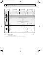
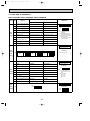
7-2. FUNCTION OF DIPSWITCH
PKFY-P32VGM-E PKFY-P40VGM-E PKFY-P50VGM-E
Switch Pole
Operation by switch
Function
ON
1
Thermistor<Intake temperature
detection>position
Built-in remote controller
Indoor unit
2
Filter clogging detection
Provided
Not provided
Address board
<At delivery>
ON
OFF
3
Filter cleaning sign
2500hr
100hr
4
Air intake
Effective
Not effective
Remote indication switching
Thermostat ON signal indication Fan output indication
Humidifier control
Always operated while the heating mode w1 Operated depends on the condition
Air flow set in case of
Fix to LOW
w3 Fix to EXTRA LOW
8
Heat thermostat OFF
Depends on setting Remote controller
w3 Depends on SW1-7
9
Auto restart
Effective
Not effective
Power source ON/OFF
Effective
Not effective
SW1
5
Mode
Selection 6
7
10
Remarks
OFF
1 2 3 4 5 6 7 8 9 10
w2
w3
NOTE:
w1 At Heating mode, fan
operating.
w2 At Heating mode, operating heat thermostat ON.
w3 SW1-7=OFF, SW1-8=ON
→Setting air flow.
SW1-7=ON, SW1-8=ON
→Indoor fan stop.
Indoor controller board
Set while the unit is off.
SW2
Capacity
1~6
code
setting
<At delivery>
Capacity
SW2
Capacity
SW2
Capacity
SW2
Set for each capacity.
P32
ON
OFF
1 2 3 4 5 6
ON
OFF
P40
1 2 3 4 5 6
P50
ON
OFF
1 2 3 4 5 6
1
Heat pump/Cooling only
Cooling only models
Heat pump models
2
Louver
Available
Not available
3
Vane
Available
Not available
4
Vane swing function
Available
Not available
SW3 5
Function
Selection 6
7
Vane horizontal angle
Second setting
First setting
Vane cooling limit angle setting w4 Horizontal angle
Down B,C
Indoor linear expansion
valve opening
Effective
Not effective
8
Heater 4deg up
Not effective
Effective
9
Target Superheat setting w5 9degrees
6degrees
Target Sub cool setting
10degrees
10
SW4
Unit 1~5
Selection
15degrees
Indoor controller board
Set while the unit is off.
<At delivery>
ON
OFF
1 2 3 4 5 6 7 8 9 10
NOTE:
w4 At cooling mode, each
angle can be used only 1
hour.
w5 sw3-9 setting
P32 = OFF
P40 = ON
P50 = OFF
Indoor controller board
Set while the unit is off.
ON
OFF
<At delivery>
ON
OFF
1 2 3 4 5
1 2 3 4 5
16
06.7.7 3:48 PM
Page 17
Switch Pole
SW11
90 1
90 1
23
78
45 6
1
SW12
23
10
Address setting should be done when
M-NET remote controller is being used.
Address can be set while the
unit is stopped.
<At delivery>
78
78
90 1
78
SW11
90 1
23
45 6
Rotary switch
SW12
23
SW12
2nd digit
address
setting
Remarks
Address board
45 6
SW11
1st digit
address
setting
Operation by switch
45 6
OC310A---1.qxp
45 6
CDE
AB
<At delivery>
SW14
F01
23
This is the switch to be used when the indoor
unit is operated with R2 series outdoor unit as
a set.
F01
45 6
CDE
AB
SW14
23
789
789
SW14
Connect
ion No.
setting
Rotary switch
Address board
Address board
SW5
Voltage
Selection
220V
2
240V
If the unit is used at the 230V or 240V area,
set the voltage to 240V.
If the unit is used at the 220V, set the voltage
to 220V.
17
<At delivery>
220V
240V
OC310A---1.qxp
06.7.7 3:49 PM
Page 18
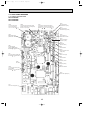
7-3. TEST POINT DIAGRAM
7-3-1. Indoor controller board
PKFY-P32VGM-E
PKFY-P40VGM-E
PKFY-P50VGM-E
CN2D
Connect to the indoor
power board (CN2S)
1 (+))
12.5-13.7V DC (Pin1
CN2M
Connect to the terminal block (TB5)
(M-NET transmission connecting wire)
24-30V DC (non-polar)
CN3A
Connect to the terminal block (TB15)
(MA-Remote controller connecting wire)
1 (+))
Between 1 to 3 8.7-13V DC (Pin1
LED1
Main power supply
(Indoor unit : 220-240V)
CN29
Pipe temperature
thermistor/Gas (TH23)
CN21
Pipe temperature
thermistor/Liquid (TH22)
LED2
Power supply for
MA-Remote controller
CN20
Room temperature
thermistor (TH21)
CN32
Connector
(Remote switch)
CND
Power supply for
indoor controller board
Between 1 to 3 220-240V AC
SW4
Model selection
CN60
Linear expansion valve
output (LEV)
CNP
Drain-up machine output (DP)
Between 1 to 3 220-240V AC
CN31
Drain sensor (DS)
SW3
Mode selection
CN51
Centrally control
FUSE
6.3A 250V
SW2
Capacity setting
CN52
Remote indication
CNDK
Connect to the indoor power
board (CNSK)
Between 1 to 3 220-240V AC
CN6V
Vane moter output (MV)
FAN
Fan motor output (MF)
18
OC310A---1.qxp
06.7.7 3:49 PM
Page 19
7-3-2. Indoor power board
PKFY-P32VGM-E
PKFY-P40VGM-E
PKFY-P50VGM-E
CN2S
Connect to the indoor power board (CN2D)
1 (+))
Between 1 to 3 12.6-13.7V DC (Pin1
CNSK
Connect to the indoor controller board (CNDK)
Between 1 to 3 220-240V AC
19
OC310A---1.qxp
8
06.7.7 3:49 PM
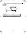
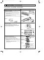
Page 20
DISASSEMBLY PROCEDURE
PKFY-P32VGM-E PKFY-P40VGM-E PKFY-P50VGM-E
PHOTOS & ILLUSTRATION
OPERATION PROCEDURE
1. REMOVE THE LOWER SIDE OF THE INDOOR UNIT FROM
THE INSTALLATION PLATE
(1) Remove the left / right corner box of the indoor unit.
(2) Hold and pull down the lower and both ends of the indoor
unit, and remove the ▼ section from the square hole.
(Refer to the figure 2.1)
Or remove the front panel and push the ▼ section down
by using alankey ,etc. from the front side.
(Refer to the figure 2.2).
(3) Unhook the top of the indoor unit from the back plate catch.
(Figure 1)
Hook
(Figure2.1)
(Figure 2.2)
Hook
Square hole
Square hole
Up Down
(Figure 3)
2. REMOVING THE FRONT PANEL
(1) Open the front grille.
(2) Remove the terminal block cover with a screw.
(3) Remove the screw 3caps then remove the set 3screws.
(4) After removing the lower side of the front panel a little,
remove it as pulling toward upper.
Terminal block cover
Front grille
(Photo 1)
Front
panel
Set screw
(Photo 2)
3. REMOVING THE INDOOR CONTROLLER BOARD
(1) Remove the terminal block cover.
(2) Remove the front panel. (See the photo 1)
(3) Remove the electrical parts box(2screws).
Motor cover
(4) Remove the electrical parts box cover(1 screw).
(5) Disconnect the connector on the indoor controller board and
Electrical parts
remove the controller board by Pulling up the hook of the
controller case.
box hook w
w To smooth works, hang the side hooks of the electrical
parts box on the hook of the motor cover.
(See the photo 3)
Set screw
Electrical parts
box
Set screw
(Photo 3)
Indoor control
p.c.board
Hook
Controller case
Electrical parts box
20
OC310A---1.qxp
06.7.7 3:49 PM
Page 21
OPERATION PROCEDURE
PHOTOS & ILLUSTRATION
4. REMOVING THE VANE MOTOR
(1) Disconnect the connector CN6V on the indoor controller
board.
(2) Remove the 2 screws of the vane motor, disconnect the
lead wire and remove the vane motor from the shaft.
(Photo 4)
Nozzle
assemble
Set screws
Lead wire
Van motor
5. REMOVING THE THERMISTOR
(1) Removing the room thermistor TH21.
1Disconnect the connector CN20 <red> on the indoor
controller board.
2Remove the room thermistor from the holder.
(2) Removing the liquid pipe thermistor TH22.
1Disconnect the connector CN21 <white> on indoor controller board.
2Remove the liquid pipe thermistor with set to the pipe.
(3) Removing the gas pipe thermistor TH23.
1Disconnect the connector CN29 <black> on indoor
controller board.
2Remove the gas pipe thermistor with set to the pipe.
6. REMOVING THE NOZZLE ASSEMBLE
(1) Disconnect the connector CN6V on the indoor controller
board.
(2) Disconnect the lead wire of the vane motor.
(3) Remove the corner cover.
(4) Pull the drain hose out from the nozzle assemble.
(5) Unhook the hook of the lower nozzle assemble and
pull the nozzle assemble toward you,then remove the
nozzle assemble by sliding it down.
(Photo 5)
Liquid
thermistor
Gas pipe
thermistor
Room
thermistor
Electrical
parts box
(Photo 6)
Hook
Drain hose
Corner cover
Nozzle assemble
7. REMOVING THE ELECTRICAL PARTS BOX
(1) Remove the terminal block cover.
(2) Remove the front panel.(See the photo 1)
(3) Disconnect the vane motor connector.
(4) Disconnect the fan motor connector from the fan motor.
(5) Remove the liquid / gas pipe thermistor.(See the photo 5)
(6) Remove the electrical parts box (2 screws).
(Photo 7)
Vane motor
connector
Liquid pipe
thermistor
Electrical
parts box
Fan motor connector
8. REMOVING THE FAN MOTOR
(1) Remove the terminal block cover.
(2) Remove the front panel.(See the photo 1)
(3) Remove the electrical parts box.(See the photo 7)
(4) Remove the nozzle assemble.(See the photo 6)
(5) Remove the fan motor leg fixing 3 screws.
(6) Unscrew the set screws using by alankey and remove it by
sliding the fan motor to right.
(7) Remove the 4 screws and remove the motor cover from the
fan motor leg.
21
(Photo 8)
(Photo 9)
Motor cover
Set
screw
Fan motor
screws
motor
leg
OC310A---1.qxp
06.7.7 3:49 PM
Page 22
OPERATION PROCEDURE
PHOTOS & ILLUSTRATION
9. REMOVING THE LINE FLOW FAN
(1) Remove the terminal block cover.
(2) Remove the front panel.(See the photo 1)
(3) Remove the electrical parts box.(See the photo 7)
(4) Remove the nozzle assembly.(See the photo 6)
(5) Remove the fan motor.(See the photo 8)
(6) Remove the pipe fixture with 2 screws.(See the photo 11)
(7) Remove the left / right screws of the heat exchanger and
pull the left-hand side up.
(8) Remove the 2screws by sliding it toward you remove the
fixture(fixing bearing).
w The fan motor is removable first , when the fan
removing is hard.
w When resetting the fan to the fan motor.
Locate and fix the shaft after installing the fan.
(Photo10)
10. REMOVING THE HEAT EXCHANGER
(1) Remove the terminal block cover.
(2) Remove the front panel.(See the photo 1)
(3) Remove the electrical parts box.(See the photo 7)
(4) Remove the corner box.
(5) Remove the nozzle assemble.(See the photo 6)
(6) Remove the 2screws and the pipe fixture.
(7) Remove the 2screws and heat exchanger.
(Photo 11)
Heat exchanger
Set screws
Fixture(fixing bearing)
Heat exchanger
Set screw
Pipe fixture
22
Set screws
OC310A---1.qxp
06.7.7 3:49 PM
9
Page 23
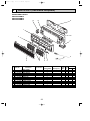
PARTS LIST (non-RoHS compliant)
STRUCTURAL PARTS
PKFY-P32VGM-E
PKFY-P40VGM-E
PKFY-P50VGM-E
13
12
11
1
10
2
9
8
3
No.
1
2
3
4
5
6
7
8
9
10
11
12
13
Parts No.
R01 89Y
R01 07Y
R01 07Y
R01 A16
R01 07Y
R01 07Y
R01 85Y
T7W B01
R01 07Y
R01 07Y
R01 07Y
R01 07Y
R01 09Y
651
092
691
500
002
096
304
294
658
635
808
623
658
Parts Name
5
4
Specifications
6
PKFYP32,P40,P50VGM-E
1
1
1
2
1
3
1
1
1
1
1
1
1
FRONT PANEL
VANE SLEEVE
FRONT GRILLE
AIR FILTER
AUTO VANE
SCREW CAP
ADDRESS CABLE
ADDRESS BOARD
CORNER COVER
BOX ASSEMBLY
BACK PLATE
UNDER COVER
CORNER COVER
23
7
Remarks
(Drawing No.)
Price
Wiring RecomDiagram mended
Unit Amount
Symbol Q'ty
A.B
OC310A---1.qxp
06.7.7 3:49 PM
Page 24
ELECTRICAL PARTS
PKFY-P32VGM-E
PKFY-P40VGM-E
PKFY-P50VGM-E
4
3
2
1
28 27 26
25 24
23
5
29
6
7
8
9
TEMP.
ON/OFF
10
11
No.
Parts No.
1 T7W A01
R01 H55
2 R01 H56
R01 H57
3 R01 07Y
4 R01 005
5 R01 07Y
6 R01 07Y
7 T7W A00
8 R01 07Y
9 R01 07Y
10 R01 07Y
11 R01 07Y
12 R01 09Y
13 R01 E04
14 R01 07Y
15 R01 07Y
16 R01 07Y
17 T7W 512
18 T7W E00
19 T7W A14
20 R01 588
21 R01 E02
22 T7W E34
23 T7W 520
24 R01 E26
25 R01 E28
26 R01 E34
27 R01 07Y
28 R01 E63
—
29
762
480
480
480
114
103
102
106
675
524
530
059
038
038
223
527
135
105
716
716
716
255
313
310
239
202
202
202
130
401
12
Parts Name
FAN MOTOR
HEAT EXCHANGER
HEAT EXCHANGER
HEAT EXCHANGER
LINE FLOW FAN
SLEEVE BEARING
BEARING MOUNT
BEARING SUPPORT
FAN GUARD
DRAIN PLUG
NOZZLE ASSY
ARM
GUIDE VANE
GUIDE VANE
VANE MOTOR
DRAIN HOSE
MOTOR COVER
RUBBER MOUNT
TERMINAL BLOCK
TERMINAL BLOCK
TERMINAL BLOCK
RUN CAPACITOR
POWER BOARD
CONTROLLER BOARD
FUSE
ROOM THERMISTOR
LIQUID PIPE THERMISTOR
GAS PIPE THERMISTOR
MOTOR SUPPORT
LINEAR EXPANSION VALVE
REMOTE CONTROLLER
13 14
Specifications
2P(1,2)
3P(M1,M2,S)
3P(L,N,; )
2.0= 440V
250V 6.3A
PAR-21MAA
15
16
PKFY-
17 18 19 20 21
22
Price
Wiring RecomRemarks
Diagram
mended
P32VGM P40VGM P50VGM (Drawing No.)
Unit Amount
Symbol Q'ty
-E
-E
-E
MF
1
1
1
1
1
1
1
1
1
1
1
1
1
1
1
1
1
1
1
1
1
1
1
1
1
1
1
2
2
2
10
10
10
4
4
4
MV
1
1
1
1
1
1
1
1
1
2
2
2
TB15
1
1
1
TB5
1
1
1
TB2
1
1
1
C1
1
1
1
P.B
1
1
1
I.B
1
1
1
FUSE
1
1
1
TH21
1
1
1
TH22
1
1
1
TH23
1
1
1
1
1
1
LEV
1
1
1
1
1
1
24
OC310A---1.qxp
06.7.7 3:49 PM
10
Page 25
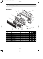
RoHS PARTS LIST
STRUCTURAL PARTS
PKFY-P32VGM-E
PKFY-P40VGM-E
PKFY-P50VGM-E
13
12
11
1
10
2
9
8
No.
RoHS
3
1
2
3
4
5
6
7
8
9
10
11
12
13
G
G
G
G
G
G
G
G
G
G
G
G
G
Parts No.
R01 E05
R01 08Y
R01 08Y
R01 A32
R01 08Y
R01 08Y
R01 A00
T7W E01
R01 08Y
R01 08Y
R01 08Y
R01 08Y
R01 10Y
651
092
691
500
002
096
304
294
658
635
808
623
658
Parts Name
5
4
Specifications
6
PKFYP32,P40,P50VGM-E
1
1
1
2
1
3
1
1
1
1
1
1
1
FRONT PANEL
VANE SLEEVE
FRONT GRILLE
AIR FILTER
AUTO VANE
SCREW CAP
ADDRESS CABLE
ADDRESS BOARD
CORNER COVER
BOX ASSEMBLY
BACK PLATE
UNDER COVER
CORNER COVER
25
7
Remarks
(Drawing No.)
Price
Wiring RecomDiagram mended
Unit Amount
Symbol Q'ty
A.B
OC310A---1.qxp
06.7.7 3:49 PM
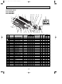
Page 26
ELECTRICAL PARTS
PKFY-P32VGM-E
PKFY-P40VGM-E
PKFY-P50VGM-E
4
3
2
1
28 27 26
23
25 24
5
29
6
7
8
9
TEMP.
ON/OFF
10
No.
1
2
3
4
5
6
7
8
9
10
11
12
13
14
15
16
17
18
19
20
21
22
23
24
25
26
27
28
29
RoHS
11
G
G
G
G
G
G
G
G
G
G
G
G
G
G
G
G
G
G
G
G
G
G
G
G
G
G
G
G
G
G
G
Parts No.
T7W A02
R01 J34
R01 J35
R01 J36
R01 E22
R01 E04
R01 08Y
R01 08Y
T7W A01
R01 08Y
R01 08Y
R01 08Y
R01 08Y
R01 10Y
R01 E14
R01 08Y
R01 08Y
R01 08Y
T7W E33
R01 E27
T7W E32
R01 E13
R01 E38
T7W E53
R01 E06
R01 H08
R01 H07
R01 H13
R01 08Y
R01 H05
—
762
480
480
480
114
103
102
106
675
524
530
059
038
038
223
527
135
105
716
246
716
255
313
310
239
202
202
202
130
401
12
Parts Name
FAN MOTOR
HEAT EXCHANGER
HEAT EXCHANGER
HEAT EXCHANGER
LINE FLOW FAN
SLEEVE BEARING
BEARING MOUNT
BEARING SUPPORT
FAN GUARD
DRAIN PLUG
NOZZLE ASSY
ARM
GUIDE VANE
GUIDE VANE
VANE MOTOR
DRAIN HOSE
MOTOR COVER
RUBBER MOUNT
TERMINAL BLOCK
TERMINAL BLOCK
TERMINAL BLOCK
RUN CAPACITOR
POWER BOARD
CONTROLLER BOARD
FUSE
ROOM THERMISTOR
LIQUID PIPE THERMISTOR
GAS PIPE THERMISTOR
MOTOR SUPPORT
LINEAR EXPANSION VALVE
REMOTE CONTROLLER
13 14
Specifications
15
16
17 18 19 20 21
PKFY-
Remarks
P32VGM P40VGM P50VGM (Drawing No.)
-E
-E
-E
1
1
1
1
22
Price
Wiring RecomDiagram mended
Unit Amount
Symbol Q'ty
MF
1
2P(1,2)
3P(M1,M2,S)
3P(L,N,; )
2.0= 440V
250V 6.3A
PAR-21MAA
1
1
1
1
1
1
1
2
10
4
1
1
1
2
1
1
1
1
1
1
1
1
1
1
1
1
1
26
1
1
1
1
1
1
1
2
10
4
1
1
1
2
1
1
1
1
1
1
1
1
1
1
1
1
1
1
1
1
1
1
1
1
1
2
10
4
1
1
1
2
1
1
1
1
1
1
1
1
1
1
1
1
1
MV
TB15
TB5
TB2
C1
P.B
I.B
FUSE
TH21
TH22
TH23
LEV
OC310A---1.qxp
06.7.7 3:49 PM
Page 27
27
OC310A---1.qxp
06.7.7 3:49 PM
Page 28
HEAD OFFICE : TOKYO BLDG., 2-7-3, MARUNOUCHI, CHIYODA-KU, TOKYO100-8310, JAPAN
cCopyright 2004 MITSUBISHI ELECTRIC ENGINEERING CO., LTD.
Distributed in Jul. 2006 No. OC310 REVISED EDITION-A PDF 8
Distributed in Apr. 2004 No. OC310 PDF 9
Made in Japan
New publication, effective Jul. 2006
Specifications subject to change without notice