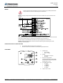
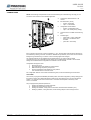
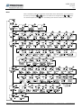
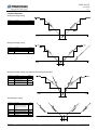
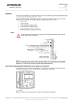
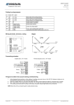
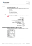
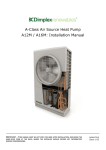
1
USER GUIDE
HLS 44
V2.0 (08.03.2012)
1 (20)
This user guide is for controllers with the software version 1.1.0, 1.1.1 or 1.1.2.
Room controller HLS 44
HLS 44 is a versatile room controller for individual room temperature
and VAV control applications. The controller can be connected to any
system that supports Modbus RTU protocol via the RS-485
connection. The bus is galvanically isolated from the controller's other
electronics. The controller has a display and touch buttons for
commissioning the controller and adjusting the user parameters,
temperature set point, for example.
The controller can control 0...10 V controlled actuators and thermal
actuators.
The output Y1 is reserved for variable air volume (VAV) control.
The Y2 output controls the fan speed:
1.
2.
EC motor: directly with the 0…10 V signal
3-speed fan: using the FCRY 3 relay module
The controller has day and night operating modes. The modes can be
controlled by external card switch, PIR occupancy detector, over
Modbus and from menu. The day mode can be activated temporarily
for a specific time by touching the "man in house" button.
A demand based and energy saving ventilation can be implemented
with a separate carbon dioxide measurement connected to the U1
input.
TECHNICAL DATA
Supply
24 Vac/dc (20…28 V), < 1 VA
NOTE: Only the 0…10 V outputs work when using DC supply voltage.
Set point
Day mode: 18…26 °C, ±3 °C, factory setting 21 °C
Night mode: Frost protection 8…50 °C, factory setting 17 °C
Accuracy (measuring
inaccuracy)
±0.5 °C
Dead zone (Dz)
Day mode: 0.2...3 °C, factory setting 0.2 °C
Night mode: 0…10 °C, factory setting 6 °C
Proportional band (Xp)
1…32 °C, factory setting 1 °C
Integration time (Tn)
50…50000 s, factory setting 300 s
Inputs
Internal temperature sensor
1 x ext. NTC10 or potential-free contact input (door or window contact or
condensation switch)
1 x DI, potential-free contact input (day/night mode control)
1 x 0...10 V (CO2 measurement, external 0...10 V set point or 0...10 V temperature
transmitter)
Outputs
4 x 0...10 Vdc (Heating/cooling actuators, VAV or Fan speed control)
2 x 24 Vac Triac outputs, < 1 A/output (thermal actuators)
Communication
RS-485 Modbus RTU, 9600/19200/38400/56000 bps, 8 data bits, parity
none/odd/even,1 stop bit (up to 247 devices per segment)
Display
LCD
Buttons
4 touch buttons
Wiring terminals
1.5 mm
Operating conditions
Humidity: 0…85 % rH non-condensing
Temperature: 0…50 ºC
Standards
2004/108/EY(EMC)
EN61000-6-3: 2001 (Emission)
EN61000-6-2: 2001 (Immunity)
Mounting
Wall surface or on the standard flush mounting box
2
Housing
IP20, ABS plastic
Dimensions (w x h x d)
87 x 86 x 32 mm
NOTE: The controller is available also with various button configurations.
Produal Oy
Keltakalliontie 18, 48770 Kotka FINLAND
Tel: +358-5-230 9200 / Fax: +358-5-230 9210
[email protected]
www.produal.com
USER GUIDE
HLS 44
2 (20)
WIRING
Device connection and commissioning can only be carried out by qualified professionals.
Always make the connections while the power is switched off.
NOTE: The supply voltage potential must be the same in the controller and in the connected 24 Vac
actuators.
The maximum triac output current is 1 A. It is recommended to connect maximum of 4 thermal actuators
to the same controller output. The total current consumption must not exceed 1 A.
The triac outputs are protected with fuses that can only be changed by the manufacturer.
NOTE: Unused inputs and outputs can also be used for transferring other measuring and control
information over the Modbus.
OPERATING AFTER A POWER FAILURE
•
The controller settings remain over the power failure.
•
Overdrives made over the Modbus are cleared during the power failure.
USER MODE
A.
Indicator light
o
o
B.
Display
o
o
C.
red = heating
green = cooling
temperature or set point
fan speed
Set point change buttons
The set point changes in larger steps
when the buttons are quickly pressed
several times in a row.
D.
Fan speed control button
o
o
o
o
o
E.
Produal Oy
Keltakalliontie 18, 48770 Kotka FINLAND
Tel: +358-5-230 9200 / Fax: +358-5-230 9210
0 = STOP
1 = Speed 1
2 = Speed 2
3 = Speed 3
A = AUTO
“Man in house” button
[email protected]
www.produal.com
USER GUIDE
HLS 44
3 (20)
COMMISSIONING
NOTE: All the settings and parameters must be checked during the commissioning. This way you can
ensure the correct function in the selected application.
A.
Terminals for external sensor or DI
contact
B.
Bus termination (120 Ω)
o
o
C.
Configuration mode selector
o
o
D.
E.
closed = terminated
open = no termination
closed = configuration mode
open = user mode (factory setting)
Terminal for HLS 44-SER commissioning
tool
Indicator lights
o
o
o
green PWR = supply voltage OK
yellow TX = transmission from
controller
yellow RX = bus activity
Every controller must have an unique bus address (1...247). All controllers inside the same segment can
be controlled by sending a common command to address zero (broadcast). The function can be used for
testing during commissioning or common control of the day/night mode changes.
The controller settings can be supplied with controller buttons or by using the HLS 44-SER
commissioning tool. The commissioning tool settings can be loaded to the controller or the controller
settings can be loaded to the configuration tool and then to other controller.
Configuration through the menu:
1.
2.
3.
4.
Remove the cover.
Set configuration mode selector to closed position.
Make the settings required by the process.
Set the configuration mode selector to open position.
The controller returns to the user mode.
For configuration with the HLS 44-SER commissioning tool, see the commissioning tool instructions.
HLS 44-SER
There is four pre-programmed editable parameter profiles, one fixed configuration (=factory settings) and
five memory slots for user defined parameter profiles in the commissioning tool. The pre-programmed
profiles 1...3 work with both HLS 44 and HLS 44-V controllers and the profile 4 works only in the
HLS 44-V controller.
The pre-programmed parameter profiles are:
1.
2.
3.
4.
Produal Oy
Heating with radiator and cooling with beam
Heating and cooling with fan coil unit
Heating with radiator, cooling with VAV and beam, demand based ventilation (CO2)
Heating by radiator, cooling with beam, on/off boosting damper control and light control
Keltakalliontie 18, 48770 Kotka FINLAND
Tel: +358-5-230 9200 / Fax: +358-5-230 9210
[email protected]
www.produal.com
USER GUIDE
HLS 44
4 (20)
MENU
Menu is activated by setting the configuration mode selector to the closed position. You can proceed in
the menu by touching the
and
buttons. The values can be changed with the
and
buttons.
The value is accepted with the
button. The following menu structure contains the factory settings.
Produal Oy
Keltakalliontie 18, 48770 Kotka FINLAND
Tel: +358-5-230 9200 / Fax: +358-5-230 9210
[email protected]
www.produal.com
USER GUIDE
HLS 44
5 (20)
CONTROL METHODS
Heating and 1-stage cooling
Parameter
Cramp
FAN
Description
Cooling stages
Fan usage
choose
1St
3
Heating and 2-stage cooling
Parameter
Cramp
CSEq
FAN
Description
Cooling stages
Sequence of cooling stages
Fan usage
choose
2St
Valve
3
Heating and 1-stage cooling, valve opens before the fan speed increases
Parameter
Cramp
Fan=
FAN
FANLO
Description
Cooling stages
Fan stage simultaneously
with the valve stage
Fan usage
Fan output scaling, low end
*)
choose
1St
OFF
3
e.g.
20%
VAV heating and cooling
Parameter
Description
VAV heating
Cramp
CSEq
NOTE: The heating stage
order is always the following:
1. Valve
2. VAV
Cooling stages
Sequence of cooling stages
Vmin%
Minimum of VAV output *)
FAN
Fan usage
HVAV
Produal Oy
choose
On
2St
Valve
e.g.
20 %
OFF
Keltakalliontie 18, 48770 Kotka FINLAND
Tel: +358-5-230 9200 / Fax: +358-5-230 9210
[email protected]
www.produal.com
USER GUIDE
HLS 44
6 (20)
PROFILE 1: HEATING WITH RADIATOR AND COOLING WITH BEAM
Principle diagram:
Input
DI1
U1
S/DI2
Output
Y1
Y2
Thermal actuator
A1
A2
x
x
Y3
Y4
Note the following parameters:
Parameter
Cramp
MJAM
Produal Oy
Modbus
register
17
22
Min
Max
Cooling stages
factory
setting
1St
1St
2St
Valve jam prevention
OFF
ON
OFF
Description
Keltakalliontie 18, 48770 Kotka FINLAND
1St = 1 stage, 2St = 2 stages
Valves can jam when they are kept on the same position for a long time. The
valve jam prevention function can be activated in these kind of situations. When
the MJAM parameter is in “ON” position, valves are opened and closed for 5
minutes once a day.
Tel: +358-5-230 9200 / Fax: +358-5-230 9210
[email protected]
www.produal.com
USER GUIDE
HLS 44
7 (20)
PROFILE 2: HEATING AND COOLING WITH FAN COIL UNIT
Principle diagram:
Input
DI1
U1
S/DI2
Output
Y1
Y2
Thermal actuator
FCRY 3 relay or EC fan
A1
A2
x
x
Y3
Y4
x
Note the following parameters:
Modbus
register
Parameter
EXT.S
40009
Cramp
17
CSEq
18
Fan=
19
Description
External temperature sensor / DI2
contact input
Cooling stages
Min
Max
OFF
OFF
3
1St
1St
2St
Valve
Valve
VAV
On
Off
On
OFF=not in use, 1= external NTC sensor, 2=DI2 door/window contact (prevents
both heating and cooling), 3=DI2 condensation switch (prevents cooling)
1St = 1 stage, 2St = 2 stages
Fmax%
40033
Maximum fan output
100.0
50.0
100.0
FANHI
40036
Fan output scaling, high end
100
0
100
Valve = valve first, VAV = VAV first
On = valve and fan stages are working simultaneously, Off = first valve stage,
then fan stage
To avoid noise coming from fan, the maximum fan speed output (EN fan) can be
limited.
The high end of the scaled EC fan control signal (0…10 V)
FANLO
40037
Fan output scaling, low end
0
0
100
The low end of the scaled EC fan control signal (0…10 V)
Fan type
3coil
3coil
EC
3coil = 3-speed fan, EC = EC fan
Fan usage
OFF
OFF
3
Fan speed 3 disabled
ON
OFF
ON
OFF=OFF, 1= cooling, 2= heating, 3= both cooling and heating
When FANLI=ON, the fan speed 3 in the automatic mode is disabled (e.g. due
the noise). However, the user can manually engage the speed 3.
When FANLI=ON, the fan speed 3 is allowed in the automatic mode.
FAn
23
FAN
40038
FANLI
24
Sequence of cooling stages
Fan stage simultaneously with the valve
stage
factory
setting
Fan control
•
The fan can be 3-speed or 0…10 V -controlled (EC motor). In the manual mode, the EC motor works so that the switch position
is 0 = 0 %, 1 = 33 %, 2 = 66 % and 3 = 100 % of the scaled control signal.
•
With the FCRY 3 relay module connected to the Y2 output you can control the speed of fan coil or 3-speed fan. For example, when
the FAN parameter is ’2’ and Fan= parameter is ’ON’, the fan works like following:
o
o
o
o
Temperature reaches the set point (DZ lower end), the valve closes and after 5 minutes the fan stops.
Temperature goes below the DZ lower limit, the valve starts to open and the fan is controlled to the speed 1 (Y2 = 3 V)
The temperature still decreases, valve opens over 70 %. The fan is directed to the speed 2 (Y2 = 6 V)
The temperature still decreases, valve opens over 90 %. The fan is directed to the speed 3 (Y2 = 10 V)
Accordingly in cooling situation, when the FAN parameter is ”1”, the controller functions according to the cooling demand
(temperature increases).
See page 5, Heating and 1-stage cooling
Valve opening before increasing the fan speed
•
When the Fan= parameter is ’ON', the EC fan that is connected to the Y2 output works simultaneously with the heating and/or
cooling valve. The fan starts when the valve starts to open and when the valve is fully open the fan works also in full speed. The fan
speed is controlled linearly between the low and high limits.
The fan works for 5 minutes after the valve is fully closed using the speed defined by FANLO parameter.
See page 5, Heating and 1-stage cooling
•
When the Fan= parameter is ’OFF’, the 3-speed fan works at speed 1 and the valve is driven fully open. The fan is then controlled to
the speed 2 (66 %) or 3 (100 %) if needed.
See page 5, Heating and 1-stage cooling, valve opens before the fan speed increases
Produal Oy
Keltakalliontie 18, 48770 Kotka FINLAND
Tel: +358-5-230 9200 / Fax: +358-5-230 9210
[email protected]
www.produal.com
USER GUIDE
HLS 44
8 (20)
PROFILE 3: HEATING WITH RADIATOR, COOLING WITH VAV AND BEAM, DEMAND BASED VENTILATION (CO2)
Principle diagram:
Input
DI1
HDH CO2transmitter
U1
S/DI2
Output
x
(PIR occupancy)
Y1
Y2
Thermal actuator
(x)
VAV
A1
A2
x
x
Y3
Y4
x
Note the following parameters:
Cramp
Modbus
register
17
CSEq
18
Sequence of cooling stages
Valve
Valve
VAV
MJAM
22
Valve jam prevention
OFF
ON
OFF
Vmin%
40034
Minimum of VAV output
0.0
0.0
50.0
Parameter
Min
Max
Cooling stages
factory
setting
1St
1St
2St
1St = 1 stage, 2St = 2 stages
Valve = valve first, VAV = VAV first
Valves can jam when they are kept on the same position for a long time. The
valve jam prevention function can be activated in these kinds of situations. When
the MJAM parameter is in “ON” position, valves are opened and closed for 5
minutes once a day.
Minimum of VAV output
The minimum level of fresh air level can be set to ensure the adequate
ventilation, for example to remove moisture in situations where the ventilated
space is not occupied.
Description
If you use CO2 measurement or occupancy detectors, note the following parameters:
Modbus
register
Parameter
Description
factory
setting
Min
Max
0
3
U1mod
40027
U1 mode
0
CO2LO
40039
Low limit P-band for CO2control
700
400
1000
0= not in use, 1=CO2 measurement, 2= external set point, 3= temp.
measurement with 0…10 V transmitter (NOTE: External sensor is not available if
the 0...10 V transmitter is selected)
Low limit P-band for CO2control
CO2HI
40040
High limit P-band for CO2control
1250
500
2000
High limit P-band for CO2control
F Air
40018
Fresh air control
0
0
3
0=CO2 / T, 1=DAY/T, 2=CO2 3=DAY
DI1bst
40026
Minimum VAV output in day mode
0%
0%
100 %
Minimum VAV output when the controller is in the day mode
Improving the fresh air usage according to the carbon dioxide level
A CO2concentration (and temperature) controlled ventilation can be implemented by connecting a CO2transmitter to the U1 input. The control
area can be defined by setting the low limit (CO2LO; factory setting 700 ppm) and high limit (CO2HI; factory setting 1250 ppm).
CO2 concentration based fresh air usage improvement requires following:
•
•
•
F Air parameter is ”0” or ”2”
U1mod parameter is ”1” (CO2 measurement)
CO2transmitter is connected to the U1 input
NOTE: When the F Air parameter is ”0”, the Y1 output is defined as maximum selection according to the CO2 concentration or temperature.
Improving fresh air usage according to the day mode
As an alternative, the fresh air supply can be improved according to the day mode. Day mode based fresh air usage improvement requires
following:
•
•
•
F Air parameter is ”1” or ”3”
Day mode control: PIR, card switch, Modbus or ”man in house” button
The DI1bst parameter (minimum VAV output when the controller is in the day mode) has a non-zero value (for example 80 %)
NOTE: When the F Air parameter is ”1”, the Y1 output is defined as maximum selection according to the previously mentioned controls or
temperature.
Produal Oy
Keltakalliontie 18, 48770 Kotka FINLAND
Tel: +358-5-230 9200 / Fax: +358-5-230 9210
[email protected]
www.produal.com
USER GUIDE
HLS 44
9 (20)
THERMOSTAT FUNCTION
By choosing the thermostat mode, the actuators can be controlled by a thermostat type control. Thermostat mode can be activated either for
cooling or heating side or for both.
•
When using the thermostat mode in the heating side, the heating valve opens fully when the temperature falls below the DZ lower
limit. The heating valve closes when the temperature reaches the set point (SP).
•
When using the thermostat mode in the cooling side, the cooling valve opens fully when the temperature rises over the DZ higher
limit. The cooling valve closes when the temperature reaches the set point (SP).
In the night mode the controller works according to the chosen function, either in thermostat mode or in frost guard mode.
The thermostat mode affects to the outputs A1, A2, Y3 and Y4.
ON/OFF actuator functions:
Input
DI1
U1
S/DI2
Output
Y1
Y2
Thermal actuator
VAV
A1
A2
x
x
Y3
Y4
(x)
FAN
(x)
Note the following parameters:
Parameter
Modbus
register
Description
factory
setting
Min
Max
OFF
OFF
3
26.0
EXT.S
40009
SPcnt
40011
External temperature sensor / DI2
contact input
Centre of user set point area
OFF=not in use, 1= external NTC sensor, 2=DI2 door/window contact (prevents
both heating and cooling), 3=DI2 condensation switch (prevents cooling)
Centre of user set point area
21.0
18.0
±SP °C
40012
Use set point area limits
±3.0
±0
±16
The user can adjust the set point within these limits.
DZ °C
40014
Dead zone
0.2
0.0
3.0
Used as a hysteresis in the thermostat mode.
nI OP
20
Night operation mode
DZ
DZ
FG
DZ = dead zone, FG = frost guard mode
FAN
40038
Fan usage
OFF
OFF
3
OFF=OFF, 1= cooling, 2= heating, 3= both cooling and heating
Fmin%
40032
Minimum fan output
0.0
0.0
50.0
Fmax%
40033
Maximum fan output
100.0
50.0
100.0
Vmin%
40034
Minimum of VAV output
0.0
0.0
50.0
Vmax%
40035
Maximum of VAV output
100.0
50.0
100.0
ThrmC
29
Thermostat function, cooling
OFF
OFF
On
OFF = P/PI controller, On = thermostat mode
ThrmH
30
Thermostat function, heating
OFF
OFF
On
OFF = P/PI controller, On = thermostat mode
Produal Oy
Keltakalliontie 18, 48770 Kotka FINLAND
Tel: +358-5-230 9200 / Fax: +358-5-230 9210
[email protected]
www.produal.com
USER GUIDE
HLS 44
10 (20)
ELECTRIC HEATER CONTROL
The controller can control an electric heater by using a solid state relay PR 50/440 between the A2 output and the heater. The relay must be
equipped with a PR 50Vac auxiliary card.
IMPORTANT: The controller is not equipped with a heater overheating protector. The overheating protection must be included in the heater
itself. The overheating alarm signal can be read by DI input, but the signal does not deactivate the heater control.
The overheating alarm signal can be connected to the DI1 or DI2 input, and the signal can then be read via the Modbus. DI input must be set
to ”not in use” position (DI1mod = 0 or EXT.S = OFF).
Input
DI1
Overheating alarm
(x)
U1
S/DI2
Output
(x)
Thermal actuator
24 Vac controlled solid
state relay
Y1
Y2
A1
A2
Y3
Y4
x
x
Note the following parameters:
Parameter
Modbus
register
EXT.S
40009
DI2dir
28
Description
External temperature sensor / DI2
contact input
DI2 operation direction (nc/no)
factory
setting
Min
OFF
OFF
3
1
0
1
Max
DI1mod
40021
DI1 mode
0
0
1
DI1dir
40022
DI1 operation direction (nc/no)
0
0
1
Produal Oy
Keltakalliontie 18, 48770 Kotka FINLAND
OFF=not in use, 1= external NTC sensor, 2=DI2 door/window contact (prevents
both heating and cooling), 3=DI2 condensation switch (prevents cooling)
0 = nc, 1 = no
0= not in use, 1= control to day mode with a nc/no switch connected to the DI1
input
in the night mode: 0 = nc, 1 = no
Tel: +358-5-230 9200 / Fax: +358-5-230 9210
[email protected]
www.produal.com
USER GUIDE
HLS 44
11 (20)
USAGE AND FUNCTIONS OF THE DI1 DIGITAL INPUT
DI1 input can be used to control the controller to the day/night mode by using a home/away switch, card reader or motion detector.
The DI1 input can be used to read other device statuses via the Modbus if the input is not needed for the room control.
Parameter
DI1mod
Modbus
register
40021
Description
DI1 mode
factory
setting
0
Min
Max
0
1
0= not in use, 1= control to day mode with a nc/no switch connected to the DI1 input
DI1dir
40022
DI1 operation direction (nc/no)
0
0
1
in the night mode: 0 = nc, 1 = no
DI1 d1
40023
DI1 delay passive to active
0
0
60
The delay in minutes, when moving from night mode to day mode
DI1 d2
40024
DI1 delay active to passive
5
0
60
The delay in minutes, when moving from day mode to night mode
USAGE AND FUNCTIONS OF THE DI2 DIGITAL INPUT
DI2 input can be used to control the controller by using a door/window contact or dew point guard with relay output.
In the door/window contact case the controller prevents cooling and heating when the door or window is open. This way the energy loss and
cooling beam condensation problems can be avoided.
In the condensation switch case, the cooling is prevented when the contact activates.
The DI2 input can be used to read other device statuses via the Modbus if the input is not needed for the room control.
Note the following parameters:
Parameter
Modbus
register
EXT.S
40009
DI2dir
28
TE ºC
40010
Produal Oy
Description
External temperature sensor / DI2
contact input
DI2 operation direction (nc/no)
Temperature sensor adjustment
Keltakalliontie 18, 48770 Kotka FINLAND
factory
setting
Min
Max
OFF
OFF
3
1
0
1
0.0
-3.0
+3.0
OFF=not in use, 1= external NTC sensor, 2=DI2 door/window contact (prevents
both heating and cooling), 3=DI2 condensation switch (prevents cooling)
0 = nc, 1 = no
The temperature measurement can be adjusted if needed
NOTE: Eliminate all error factors that can affect to the temperature measurement
before changing this parameter. The parameter cannot be reset to the factory
value.
Tel: +358-5-230 9200 / Fax: +358-5-230 9210
[email protected]
www.produal.com
USER GUIDE
HLS 44
12 (20)
CONTROL TO THE DAY AND NIGHT MODES
•
NIGHT parameter is ”OFF”: The controller is in fixed day mode.
•
NIGHT parameter is ”On”: The controller moves to day mode when the first control requests the day mode. The controller moves to
the night mode when the last control requests the night mode.
Example:
When the controller moves to the day mode, following happens:
1.
The fresh air usage is improved (DI1bst parameter defines the improvement amount, 0…100 %).
Fresh air usage improvement can be prevented by setting the DI1bst parameter value to 0 %.
2.
The temperature set point defined by the SP:nd parameter becomes effective.
3.
The day mode dead zone becomes effective and the controller moves from possible frost guard mode to controlling mode.
Note the following parameters:
Parameter
EXT.S
DI2dir
Modbus
register
40009
External temperature sensor / DI2
contact input
DI2 operation direction (nc/no)
factory
setting
Min
Max
OFF
OFF
3
OFF=not in use, 1= external NTC sensor, 2=DI2 door/window contact (prevents
both heating and cooling), 3=DI2 condensation switch (prevents cooling)
0 = nc, 1 = no
0= not in use, 1= control to day mode with a nc/no switch connected to the DI1
input
in the night mode: 0 = nc, 1 = no
1
0
1
DI1mod
40021
DI1 mode
0
0
1
DI1dir
40022
DI1 operation direction (nc/no)
0
0
1
DI1 d1
40023
DI1 delay passive to active
0
0
60
The delay in minutes, when moving from night mode to day mode
DI1 d2
40024
5
0
60
The delay in minutes, when moving from day mode to night mode
ext t
40025
DI1bst
40026
SP:nd
21
DI1 delay active to passive
Duration of temporary day mode,
minutes
Minimum VAV output in day mode
The effective set point after night mode
to day mode change
NIGHT
14
Produal Oy
28
Description
Night/day mode selection
Keltakalliontie 18, 48770 Kotka FINLAND
120
1
480
0%
0%
100 %
OFF
OFF
On
OFF
OFF
On
Minimum VAV output when the controller is in the day mode
OFF = The last value set by the user
On = The value from Modbus
OFF = the controller is in fixed day mode, On = the controller is in the night mode
if not separately controlled to the day mode.
Tel: +358-5-230 9200 / Fax: +358-5-230 9210
[email protected]
www.produal.com
USER GUIDE
HLS 44
13 (20)
USING THE EXPANDED DEAD ZONE IN THE NIGHT MODE
With the expanded dead zone you can save energy by allowing lower temperature and ventilation. It is also possible to set the night dead zone
to a smaller value than the day dead zone.
When the nl OP parameter is ”DZ”, the controller works just like in the day mode but uses the night dead zone. The night dead zone is defined
with the NDZ°C parameter.
Day mode:
Night mode:
Note the following parameters:
Parameter
EXT.S
nI OP
NDZ°C
Modbus
register
40009
20
40019
Description
factory
setting
Min
Max
OFF
OFF
3
External temperature sensor / DI2 contact
input
Night operation mode
DZ
DZ
FG
Night mode dead zone
6.0
0.0
10.0
OFF=not in use, 1= external NTC sensor, 2=DI2 door/window contact (prevents
both heating and cooling), 3=DI2 condensation switch (prevents cooling)
DZ = dead zone, FG = frost guard mode
ASYMMETRIC DEAD ZONE
The dead zone centre relation to the temperature set point can be adjusted with the SP_Dz parameter (0…100 %) according to the following
figure.
Produal Oy
Keltakalliontie 18, 48770 Kotka FINLAND
Tel: +358-5-230 9200 / Fax: +358-5-230 9210
[email protected]
www.produal.com
USER GUIDE
HLS 44
14 (20)
FUNCTIONING AS A FROST GUARD IN THE NIGHT MODE
When the temperature drops below the frost guard set point (FG °C parameter), the heating valve opens and the fan starts (the FAN
parameter must be ”2” or ”3”) at speed 1. The EC motor control signal is 33 %.
When the temperature rises 2 °C over the set point (FG °C parameter), the heating valve closes and the fan stops. The procedure repeats until
the controller moves to day mode.
Day:
Night:
Note the following parameters:
Parameter
EXT.S
Modbus
register
40009
nI OP
20
FG °C
40020
Produal Oy
Description
factory
setting
Min
Max
External temperature sensor / DI2
contact input
Night operation mode
OFF
OFF
3
DZ
DZ
FG
Frost guard thermostat set point
17.0
8.0
50.0
Keltakalliontie 18, 48770 Kotka FINLAND
OFF=not in use, 1= external NTC sensor, 2=DI2 door/window contact (prevents
both heating and cooling), 3=DI2 condensation switch (prevents cooling)
DZ = dead zone, FG = frost guard mode
Tel: +358-5-230 9200 / Fax: +358-5-230 9210
[email protected]
www.produal.com
USER GUIDE
HLS 44
15 (20)
TEMPERATURE SET POINT
The temperature set point can be one of the following:
1.
Set with the controller buttons (parameters SPcnt and ±SP °C).
2.
Set by external 0...10 V signal (U1mod parameter must be ”2”).
The external set point 0...10 V signal range is the same as the set point area defined in the menu (parameters SPcnt and ±SP °C).
3.
Set via the Modbus.
4.
The frost guard set point (FG °C parameter) in the night mode, if the frost guard mode is selected to the night mode (nl OP
parameter is ”FG”).
The change from night mode to day mode affects also to the temperature set point. With the Sp:nd parameter you can select the set point
either to be the latest user given value or to be read via Modbus. The user given value can be the 0...10 V signal connected to the U1 input or
the value set by the controller buttons.
Modbus
register
40011
Parameter
SPcnt
Min
Max
Centre of user set point area
factory
setting
21.0
18.0
26.0
Centre of user set point area
The user can adjust the set point within these limits.
Description
±SP °C
40012
User set point area limits ±°C
±3.0
±0
±16
SP_Dz
40015
Set point position in dead zone
50
0
100
FG °C
40020
SP:nd
21
Frost guard thermostat set point
The effective set point after night
mode to day mode change
U1mod
40027
U1 mode
17.0
8.0
50.0
OFF
OFF
On
0
0
3
OFF = The last value set by the user
On = The value from Modbus
0= not in use, 1=CO2 measurement, 2= external set point, 3= temp. measurement
with 0…10 V transmitter (NOTE: External sensor is not available if the 0...10 V
transmitter is selected)
SENSOR SELECTION
The temperature information can be imported to the controller by using following methods:
1.
Controller inner temperature measurement (EXT.S parameter is ”0”, ”2” or ”3”)
2.
External temperature measurement with NTC10 sensor (EXT.S parameter is ”1”)
3.
External 0...10 V temperature measurement (U1mod parameter is ”3”)
NOTE: The external 0…10 V temperature transmitter range must be 0…+50 °C.
The set point can be read from one controller and then fed to other controllers in cases where multiple controllers are located in the same
space.
Note the following parameters:
Parameter
Modbus
register
Description
factory
setting
Min
Max
OFF
OFF
3
EXT.S
40009
External temperature sensor / DI2
contact input
TE ºC
40010
Temperature sensor adjustment
0.0
-3.0
3.0
U1mod
40027
U1 mode
0
0
3
OFF=not in use, 1= external NTC sensor, 2=DI2 door/window contact (prevents
both heating and cooling), 3=DI2 condensation switch (prevents cooling)
The temperature measurement can be adjusted if needed
NOTE: Eliminate all error factors that can affect to the temperature measurement
before changing this parameter. The parameter cannot be reset to the factory
value.
0= not in use, 1=CO2 measurement, 2= external set point, 3= temp.
measurement with 0…10 V transmitter (NOTE: External sensor is not available if
the 0...10 V transmitter is selected)
OUTPUT LIMITATIONS
It is possible to limit minimum and maximum values of each output separately. The controller does not drive the output outside the given limits.
For example, setting the heating output minimum limit is one way to prevent discomfort of chilled air that flows down the window. The limits
can be over driven only by controlling the outputs directly via the Modbus (Modbus overdrive).
Input
DI1
U1
S/DI2
Output
Y1
Y2
A1
A2
Y3
Y4
x
x
x
x
x
x
Note the following parameters:
Parameters
Cmin%
Modbus
register
40028
Description
Minimum of cooling actuator
factory
setting
0.0
Min
Max
0.0
50.0
Cmax%
40029
Maximum of cooling actuator
100.0
50.0
100.0
Hmin%
40030
Minimum of heating actuator
0.0
0.0
50.0
Hmax%
40031
Maximum of heating actuator
100.0
50.0
100.0
Fmin%
40032
Minimum fan output
0.0
0.0
50.0
Fmax%
40033
Maximum fan output
100.0
50.0
100.0
Vmin%
40034
Minimum of VAV output
0.0
0.0
50.0
Vmax%
40035
Maximum of VAV output
100.0
50.0
100.0
Produal Oy
Keltakalliontie 18, 48770 Kotka FINLAND
Tel: +358-5-230 9200 / Fax: +358-5-230 9210
[email protected]
www.produal.com
USER GUIDE
HLS 44
16 (20)
OUTPUT OVERDRIVES
All outputs can be over driven separately by the Modbus.
Coils
Register
Parameter description
Data Type
Value
Range
1
Cooling PWM overdrive enable (A1)
Bit
Off=0, On=1
Off - On
Default
0
2
Cooling 0-10V overdrive enable (Y3)
Bit
Off=0, On=1
Off - On
0
3
Heating PWM overdrive enable (A2)
Bit
Off=0, On=1
Off - On
0
4
Heating 0-10V overdrive enable (Y4)
Bit
Off=0, On=1
Off - On
0
5
VAV overdrive enable (Y1)
Bit
Off=0, On=1
Off - On
0
6
FAN overdrive enable (Y2)
Bit
Off=0, On=1
Off - On
0
Default
Input registers
Register
Parameter description
Data Type
Value
Range
30008
Current Cooling (controller)
Signed 16
0…1000
0 …10.00 V
30009
Current Heating (controller)
Signed 16
0…1000
0 …10.00 V
30010
Current FAN Speed (controller)
Signed 16
0…4
0-1-2-3-4
30011
FAN speed (connector)
Signed 16
0…1000
0 …10.00 V
30012
VAV control (connector)
Signed 16
0…1000
0 …10.00 V
30013
Cooling control (connector)
Signed 16
0…1000
0 …10.00 V
30014
Heating control (connector)
Signed 16
0…1000
0 …10.00 V
Holding registers
Register
Parameter description
Data Type
Value
Range
40001
FAN speed by Modbus
Signed 16
0…4
0-1-2-3-4
0
40003
Overdrive Cooling PWM by Modbus (A1)
Signed 16
0 … 1000
0,00 … 100,0 %
0
40004
Overdrive Cooling 0...10 V by Modbus (Y3)
Signed 16
0…1000
0 …10.00 V
0
40005
Overdrive Heating PWM by Modbus (A2)
Signed 16
0 … 1000
0,00 … 100,0 %
0
40006
Overdrive Heating 0...10 V by Modbus (Y4)
Signed 16
0…1000
0 …10.00 V
0
40007
Overdrive VAV by Modbus (Y1)
Signed 16
0…1000
0 …10.00 V
0
40008
Overdrive FAN by Modbus (Y2)
Signed 16
0…1000
0 …10.00 V
0
40028
Minimum of cooling actuator
Signed 16
0 … 500
0,0 … 50,0 %
0
40029
Maximum of cooling actuator
Signed 16
500 … 1000
50,0 … 100,0 %
1000
40030
Minimum of heating actuator
Signed 16
0 … 500
0,0 … 50,0 %
0
40031
Maximum of heating actuator
Signed 16
500 … 1000
50,0 … 100,0 %
1000
40032
Minimum of fan output
Signed 16
0 … 500
0,0 … 50,0 %
0
40033
Maximum of fan output
Signed 16
500 … 1000
50,0 … 100,0 %
1000
40034
Minimum of VAV output
Signed 16
0 … 500
0,0 … 50,0 %
0
40035
Maximum of VAV output
Signed 16
500 … 1000
50,0 … 100,0 %
1000
Produal Oy
Keltakalliontie 18, 48770 Kotka FINLAND
Tel: +358-5-230 9200 / Fax: +358-5-230 9210
[email protected]
Default
www.produal.com
USER GUIDE
HLS 44
17 (20)
SERVICE ALARM
If the temperature does not reach the dead zone in 120 hours, the Modbus register SERVICE ALARM bit changes to ”ON” position. The alarm
is for information purposes only and does not affect to the controller functions. The alarm can be reset via the Modbus.
NETWORK DESCRIPTION
Up to 247 controllers can be connected to a single network segment. The following diagram illustrates a typical installation where the room
controllers are connected on the floor level to a gateway server.
Produal Oy
Keltakalliontie 18, 48770 Kotka FINLAND
Tel: +358-5-230 9200 / Fax: +358-5-230 9210
[email protected]
www.produal.com
USER GUIDE
HLS 44
18 (20)
MODBUS REGISTERS AND FUNCTION CODES
The device supports the following Modbus registers and function codes. The parameter memory durability allows at least 1 million writing
cycles.
Supported MODBUS functions:
0x01
Read Coils
0x02
Read Discrete Inputs
0x03
Read Holding Registers
0x04
Read Input Registers
0x05
Write Single Coil
0x06
Write Single Register
0x0F
Write Multiple Coils
0x10
Write Multiple Registers
0x17
Read/Write Multiple Registers
NOTE: If you try to write a parameter value that is beyond the parameter value range, the value will be replaced by the nearest acceptable
value. For example, if you write 270 to the register 40011, the value will be replaced by 260.
Register
Parameter description
Data Type
Value
Range
Default
COILS
1
Cooling PWM overdrive enable (A1)
Bit
Off=0, On=1
Off - On
0
2
Cooling 0-10V overdrive enable (Y3)
Bit
Off=0, On=1
Off - On
0
3
Heating PWM overdrive enable (A2)
Bit
Off=0, On=1
Off - On
0
4
Heating 0-10V overdrive enable (Y4)
Bit
Off=0, On=1
Off - On
0
5
VAV overdrive enable (Y1)
Bit
Off=0, On=1
Off - On
0
6
FAN overdrive enable (Y2)
Bit
Off=0, On=1
Off - On
0
7
On/Off damper overdrive enable (B1)
Bit
Off=0, On=1
Off - On
0
8
Light control overdrive enable (B2)
Bit
Off=0, On=1
Off - On
0
9
Overdrive On/off damper by Modbus (B1)
Bit
Off=0, On=1
Off - On
0
10
Overdrive Light control by Modbus (B2)
Bit
Off=0, On=1
Off - On
0
11
SERVICE ALARM RESET
Bit
Off=0, On=1
Off - On
0
12
Cooling disabled
Bit
Off=0, On=1
Off - On
0
13
Heating disabled
Bit
Off=0, On=1
Off - On
0
14
NIGHT MODE
Bit
Off=0, On=1
Off - On
0
15
Cooling output mode (0:DIR, 1:REV)
Bit
Off=0, On=1
Off - On
0
16
Heating output mode (0:DIR, 1:REV)
Bit
Off=0, On=1
Off - On
0
17
Number of cooling stages (0:1 stage, 1:2 stages)
Bit
Off=0, On=1
Off - On
0
18
Sequence of cooling stages (0:Valve first , 1:VAV first)
Bit
Off=0, On=1
Off - On
0
19
Fan stage simultaneously with valve stage
Bit
Off=0, On=1
Off - On
1
20
Night operation mode (0:Dead zone, 1:Frost guard)
Bit
Off=0, On=1
Off - On
0
21
Effective set point after night mode to day mode change
(0:User, 1:Modbus)
Bit
Off=0, On=1
Off - On
0
22
Valve jam prevention
Bit
Off=0, On=1
Off - On
0
23
Fan type (0: 3-speed, 1:EC)
Bit
Off=0, On=1
Off - On
0
24
Fan speed 3 disabled
Bit
Off=0, On=1
Off - On
0
25
Effective fan speed after night mode to day mode change
(0:User, 1:Modbus)
Bit
Off=0, On=1
Off - On
0
26
VAV for heating
Bit
Off=0, On=1
Off - On
0
27
Display (0:temperature, 1:Set point)
Bit
Off=0, On=1
Off - On
0
28
DI2 operation direction (0:NC, 1:NO)
Bit
Off=0, On=1
Off - On
1
29
Thermostat function, cooling (0: P/PI, 1:thermostat)
Bit
Off=0, On=1
Off - On
0
30
Thermostat function, heating (0: P/PI, 1:thermostat)
Bit
Off=0, On=1
Off - On
0
Produal Oy
Keltakalliontie 18, 48770 Kotka FINLAND
Tel: +358-5-230 9200 / Fax: +358-5-230 9210
[email protected]
www.produal.com
USER GUIDE
HLS 44
19 (20)
Register
Parameter description
Data Type
Value
Range
Default
31
Y1 for cooling (off = VAV)
32
Y2 for heating (off = FAN)
Bit
Off=0, On=1
Off - On
0
Bit
Off=0, On=1
Off - On
0
DISCRETE INPUTS
10001
Occupied by PIR
Bit
Off=0, On=1
Off - On
10002
Occupied by “man in a house”
Bit
Off=0, On=1
Off - On
10003
DAY EXTENSION
Bit
Off=0, On=1
Off - On
10004
DI1 Input state
Bit
Off=0, On=1
Off - On
10005
DI2 Input state
Bit
Off=0, On=1
Off - On
10006
CO2 overdrives
Bit
Off=0, On=1
Off - On
16 bits
16 bits
16 bits
16 bits
16 bits
16 bits
Signed 16
-600…600
-60.0…60.0 °C
INPUT REGISTERS
Unsigned
16
Unsigned
16
Unsigned
16
30001
DISCRETE INPUTS (16 - 1)
30002
COILS (16 - 1)
30003
COILS (32 - 17)
30004
Temperature
30005
External Temperature
Signed 16
-600…600
-60.0…60.0 °C
30006
CO2
Signed 16
0…2000
0…2000 ppm
30007
Effective Set point
Signed 16
50…500
5.0…50.0 °C
30008
Current Cooling (controller)
Signed 16
0…1000
0 …10.00 V
30009
Current Heating (controller)
Signed 16
0…1000
0 …10.00 V
30010
Current FAN Speed (controller)
Signed 16
0…4
0-1-2-3-4
30011
FAN speed (connector)
Signed 16
0…1000
0 …10.00 V
30012
VAV control (connector)
Signed 16
0…1000
0 …10.00 V
30013
Cooling control (connector)
Signed 16
0…1000
0 …10.00 V
30014
Heating control (connector)
Signed 16
0…1000
0 …10.00 V
30015
U1 Input” Value
Signed 16
0…1000
0 …10.00 V
30016
EXT NTC Value (connector)
Signed 16
-600…600
-60.0…60.0 °C
30017
VAV/Boosting control (0:CO2, 1:T, 2:PIR)
Signed 16
0…2
0 - 1- 2
30018
Set point by user
Signed 16
±SP ºC
±SP ºC
30019
Fan control by user
Signed 16
0…4
0-1-2-3-4
30020
User set point deviation
Signed 16
±SP
±SP
HOLDING REGISTERS
40001
FAN Speed by Modbus
Signed 16
0…4
0-1-2-3-4
0
40002
Set point by Modbus
Signed 16
80 … 500
8,0 … 50,0 °C
210
40003
Overdrive Cooling PWM by Modbus (A1)
Signed 16
0 … 1000
0,00 … 100,0 %
0
40004
Overdrive Cooling 0...10 V by Modbus (Y3)
Signed 16
0…1000
0 …10.00 V
0
40005
Overdrive Heating PWM by Modbus (A2)
Signed 16
0 … 1000
0,00 … 100,0 %
0
40006
Overdrive Heating 0...10 V by Modbus (Y4)
Signed 16
0…1000
0 …10.00 V
0
40007
Overdrive VAV by Modbus (Y1)
Signed 16
0…1000
0 …10.00 V
0
40008
Overdrive FAN by Modbus (Y2)
Signed 16
0…1000
0 …10.00 V
0
40009
External temperature sensor / DI2 input (0:Not used, 1:ext T,
2:door/window, 3:condensation switch)
Signed 16
0…3
0-1-2-3
0
40010
Temperature sensor adjustment
Signed 16
-30 … 30
-3,0 … 3,0 °C
0
Produal Oy
Keltakalliontie 18, 48770 Kotka FINLAND
Tel: +358-5-230 9200 / Fax: +358-5-230 9210
[email protected]
www.produal.com
USER GUIDE
HLS 44
20 (20)
Register
Parameter description
Data Type
Value
Range
Default
40011
Centre of user set point area
Signed 16
180 … 260
18,0 … 26,0 °C
210
40012
User set point area limits
Signed 16
0 … 160
0,0 … 16,0 °C
30
40013
Control mode
Signed 16
0…1
P - PI
1
40014
Dead zone
Signed 16
0 … 30
0,0 … 3,0 °C
2
40015
Set point position in dead zone
Signed 16
0 … 100
0 … 100 %
50
40016
Proportional band
Signed 16
10 … 320
1,0 … 32,0 °C
10
40017
Integral time
Signed 16
50 … 5000
50 … 5000 s
300
40018
Fresh air control (0:CO2/T, 1:DAY/T, 2: CO2, 3:DAY)
Signed 16
0…3
0-1-2-3
0
40019
Night mode dead zone
Signed 16
0 … 100
0,0 … 10,0 °C
60
40020
Frost guard thermostat set point
Signed 16
80 … 500
8,0 … 50,0 °C
170
40021
DI1 mode (0:not used, 1:day/night change by ext. contact)
Signed 16
0…1
0-1
0
40022
DI1 operation direction (0:NC, 1:NO)
Signed 16
0…1
0-1
0
40023
DI1 delay passive to active
Signed 16
0 … 60
0 … 60 min
0
40024
DI1 delay active to passive
Signed 16
0 … 60
0 … 60 min
5
40025
Duration of temporary day mode
Signed 16
1 … 480
1 … 480 min
120
40026
Minimum VAV output in day mode
Signed 16
0 … 1000
0,0 … 100,0 %
0
40027
U1 mode (0:not used, 1:CO2, 2:T set point, 3:T meas)
Signed 16
0…3
0-1-2-3
0
40028
Minimum of cooling actuator
Signed 16
0 … 500
0,0 … 50,0 %
0
40029
Maximum of cooling actuator
Signed 16
500 … 1000
50,0 … 100,0 %
1000
40030
Minimum of heating actuator
Signed 16
0 … 500
0,0 … 50,0 %
0
40031
Maximum of heating actuator
Signed 16
500 … 1000
50,0 … 100,0 %
1000
40032
Minimum of fan output
Signed 16
0 … 500
0,0 … 50,0 %
0
40033
Maximum of fan output
Signed 16
500 … 1000
50,0 … 100,0 %
1000
40034
Minimum of VAV output
Signed 16
0 … 500
0,0 … 50,0 %
0
40035
Maximum of VAV output
Signed 16
500 … 1000
50,0 … 100,0 %
1000
40036
Fan output scaling, high end
Signed 16
0 … 1000
0,00 … 100,0 %
1000
40037
Fan output scaling, low end
Signed 16
0 … 1000
0,00 … 100,0 %
0
40038
Fan usage (0:Off, 1:cooling, 2:heating, 3:cooling and heating)
Signed 16
0…3
0-1-2-3
0
40039
Low limit P-band for CO2 control
Signed 16
400 … 1000
400 … 1000ppm
700
40040
High limit P-band for CO2 control
Signed 16
500 … 2000
500 … 2000ppm
1250
Produal Oy
Keltakalliontie 18, 48770 Kotka FINLAND
Tel: +358-5-230 9200 / Fax: +358-5-230 9210
[email protected]
www.produal.com