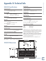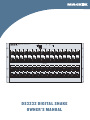
1
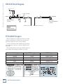
POWER
U-NET
DS3232
24-BIT / 96kHz DIGITAL SNAKE
PUSH
1
PUSH
2
PUSH
17
PUSH
3
PUSH
18
PUSH
4
PUSH
19
PUSH
5
PUSH
20
PUSH
6
PUSH
21
PUSH
22
PUSH
INPUTS
8
7
PUSH
PUSH
23
PUSH
24
PUSH
1
2
3
4
5
6
7
17
18
19
20
21
22
23
9
PUSH
25
PUSH
RETURNS
8
24
10
PUSH
11
PUSH
26
PUSH
12
PUSH
27
PUSH
13
PUSH
28
PUSH
14
PUSH
29
PUSH
15
PUSH
30
PUSH
16
PUSH
31
PUSH
32
PUSH
9
10
11
12
13
14
15
16
25
26
27
28
29
30
31
32
DS3232 DIGITAL SNAKE
OWNER’S MANUAL
DS3232 DIGITAL SNAKE
Important Safety Instructions
1. Read these instructions. 2. Keep these instructions.
3. Heed all warnings.
4. Follow all instructions.
5. Do not use this apparatus near water.
6. Clean only with dry cloth.
7. Do not block any ventilation openings. Install in accordance with the
manufacturer’s instructions.
8. Do not install near any heat sources such as radiators, heat registers,
stoves, or other apparatus (including amplifiers) that produce heat.
9. Do not defeat the safety purpose of the polarized or grounding-type
plug. A polarized plug has two blades with one wider than the other.
A grounding-type plug has two blades and a third grounding prong.
The wide blade or the third prong are provided for your safety. If the
provided plug does not fit into your outlet, consult an electrician for
replacement of the obsolete outlet.
10.Protect the power cord from being walked on or pinched particularly at
plugs, convenience receptacles, and the point where they exit from the
apparatus.
11.Only use attachments/accessories specified by the manufacturer.
12.Use only with a cart, stand, tripod, bracket, or
table specified by the manufacturer, or sold with
the apparatus. When a cart is used, use caution
when moving the cart/apparatus combination to
avoid injury from tip-over.
PORTABLE CART
WARNING
13.Unplug this apparatus during lightning storms or
when unused for long periods of time.
14.Refer all servicing to qualified service personnel. Servicing is required
when the apparatus has been damaged in any way, such as powersupply cord or plug is damaged, liquid has been spilled or objects have
fallen into the apparatus, the apparatus has been exposed to rain or
moisture, does not operate normally, or has been dropped.
15.This apparatus has been designed with Class-I construction and must
be connected to a mains socket outlet with a protective earthing connection (the third grounding prong).
16.This apparatus has been equipped with an all-pole, rocker-style AC
mains power switch. This switch is located on the rear panel and
should remain readily accessible to the user.
CAUTION
RISK OF ELECTRIC SHOCK. DO NOT OPEN
CAUTION: TO REDUCE THE RISK OF ELECTRIC SHOCK DO NOT REMOVE COVER (OR BACK)
NO USER-SERVICEABLE PARTS INSIDE. REFER SERVICING TO QUALIFIED PERSONNEL
The lightning flash with arrowhead symbol within an equilateral triangle is
intended to alert the user to the presence of uninsulated "dangerous
voltage" within the product's enclosure, that may be of sufficient magnitude
to constitute a risk of electric shock to persons.
The exclamation point within an equilateral triangle is intended to alert the
user of the presence of important operating and maintenance (servicing)
instructions in the literature accompanying the appliance.
17.NOTE: This equipment has been tested and found to comply with
the limits for a Class A digital device, pursuant to part 15 of the FCC
Rules. These limits are designed to provide reasonable protection
against harmful interference in a residential installation. This
equipment generates, uses, and can radiate radio frequency energy
and, if not installed and used in accordance with the instructions,
may cause harmful interference to radio communications. However,
there is no guarantee that interference will not occur in a particular
installation.
If this equipment does cause harmful interference to radio or
television reception, which can be determined by turning the
equipment off and on, the user is encouraged to try to correct the
interference by one or more of the following measures:
• Reorient or relocate the receiving antenna.
• Increase the separation between the equipment and the receiver.
• Connect the equipment into an outlet on a circuit different from
that to which the receiver is connected.
• Consult the dealer or an experienced radio/TV technician for help.
CAUTION: Changes or modifications to this device not expressly
approved by LOUD Technologies Inc. could void the user’s authority to
operate the equipment under FCC rules.
18.This apparatus does not exceed the Class A/Class B (whichever is
applicable) limits for radio noise emissions from digital apparatus as
set out in the radio interference regulations of the Canadian Department
of Communications.
ATTENTION — Le présent appareil numérique n’émet pas de bruits
radioélectriques dépassant las limites applicables aux appareils numériques de
class A/de class B (selon le cas) prescrites dans le réglement sur le brouillage
radioélectrique édicté par les ministere des communications du Canada.
19.Exposure to extremely high noise levels may cause permanent hearing
loss. Individuals vary considerably in susceptibility to noise-induced
hearing loss, but nearly everyone will lose some hearing if exposed to
sufficiently intense noise for a period of time. The U.S. Government’s
Occupational Safety and Health Administration (OSHA) has specified
the permissible noise level exposures shown in the following chart.
According to OSHA, any exposure in excess of these permissible limits
could result in some hearing loss. To ensure against potentially dangerous exposure to high sound pressure levels, it is recommended that all
persons exposed to equipment capable of producing high sound pressure levels use hearing protectors while the equipment is in operation.
Ear plugs or protectors in the ear canals or over the ears must be worn
when operating the equipment in order to prevent permanent hearing
loss if exposure is in excess of the limits set forth here.
Duration, per Sound Level dBA,
Typical Example
day in hours Slow Response
8
6
4
3
2
1.5
1
0.5
0.25 or less
90
92
95
97
100
102
105
110
115
Duo in small club
Subway Train
Very loud classical music
Fooyoung screaming at desTROYer about deadlines
Loudest parts at a rock concert
WARNING — To reduce the risk of fire or electric shock, do not
expose this apparatus to rain or moisture.
Correct Disposal of this product: This symbol indicates that this product should not be disposed of with your household waste, according to the WEEE Directive
(2002/96/EC) and your national law. This product should be handed over to an authorized collection site for recycling waste electrical and electronic equipment (EEE). Improper handling
of this type of waste could have a possible negative impact on the environment and human health due to potentially hazardous substances that are generally associated with EEE. At the
same time, your cooperation in the correct disposal of this product will contribute to the effective usage of natural resources. For more information about where you can drop off your waste
equipment for recycling, please contact your local city office, waste authority, or your household waste disposal service.
2
DS3232 DIGITAL SNAKE
Important Safety Instructions.........................2 Appendix A: Service Information....................9
Introduction..........................................................4 Troubleshooting...........................................................................9
Features . .......................................................................................4
Repair............................................................................................ 10
Getting Started....................................................4 Appendix B: Technical Info..............................11
Connections..................................................................................4
Setup............................................................................................... 5
DS3232 Features....................................................7
Front Panel.................................................................................... 7
1. Network Connection ..................................................... 7
2. POWER Indicator ........................................................... 7
3. COMM Indicator . ........................................................... 7
4. INPUTS 1-32....................................................................... 7
5. RETURNS 1-32....................................................................8
Rear Panel......................................................................................8
6. POWER Switch . ..............................................................8
7. POWER Receptacle ........................................................8
8. Fan ......................................................................................8
DS3232 Specifications................................................................ 11
DS3232 Dimensions.................................................................... 11
DS3232 Block Diagram...............................................................12
TT24 ADAT Outputs...................................................................12
Input and Output Wiring.........................................................13
RJ45 Wiring...................................................................................13
Owner’s Manual
Table of Contents
Appendix C: Hookup Diagram........................ 14
DS3232 Limited Warranty................................ 15
Don’t forget to visit our website at www.mackie.com for more
information about this and other Mackie products.
Part No. SW0352 Rev. E 03/12
©2007-2012 LOUD Technologies Inc. All Rights Reserved.
R
Owner’s Manual
3
DS3232 DIGITAL SNAKE
Introduction
HOW TO USE THIS MANUAL
Thank you for choosing the Mackie DS3232 Digital
Snake to expand the mixing capabilities of your digital
mixer. The DS3232 provides 32 balanced inputs and
32 balanced outputs, all easily accessible in a six rack
space box.
We know that many of you can’t wait to get your new
Digital Snake hooked up, and you’re probably not going
to read the manual first (sigh!). So the next section is a
Quick-Start Guide to help you get the DS3232 set up fast
so you can start using it right away.
The 32 mic preamps in the DS3232 are comprised of
our highest-quality studio-grade mic preamps, rivaling
expensive stand-alone boutique mic preamps. The A/D
and D/A converters in the DS3232 are pristine 24-bit
converters operating up to 96 kHz. The digital audio is
connected to the mixer using standard Cat5e cable, at
distances up to 300 feet (90 meters).
Then, when you have time, read the Features Description section. In this section, you’ll find illustrations with
each feature numbered. If you want to know more about
a feature, simply locate it on the appropriate illustration, notice the number attached to it, and find that
number in the nearby paragraphs.
This allows you to connect your microphones and DI’s
to the DS3232 on-stage, and run a single Cat5e cable
back to your FOH mixing position, eliminating signal
degradation and noise that often results from long runs
of analog cable. Not to mention the pounds of copper
you save by not running a 300 foot 32-channel audio
snake from the stage to the mixing console.
Features
•
32 x 32 I/O with XLR connectivity
•
Mic preamps and A/D converters are digitally controlled by the mixing console
•
24-bit/96 kHz bi-directional digital audio
•
Can be connected up to 300 feet from the mixing
console
•
Eliminates signal degradation and noise associated
with long runs of analog cable
•
Rack mountable (6 rack spaces)
More resources on our website at www.mackie.com.
Click Support on the opening page of our website to
find answers to many of your questions. The FAQ (Frequently Asked Questions) section is filled with answers
to many of the questions our Technical Support staff has
fielded over the years.
Check out the glossary for explanations of many of the
pro-audio terms used in our manuals.
Visit our forums to seek help from our online community of Mackie users.
Getting Started
READ THIS PAGE!!
Even if you’re one of those people
who never read manuals, all we ask
is that you read this page and the
next now before you begin using the
DS3232. You’ll be glad you did!
Connections
Please write your serial number here for future
reference (i.e., insurance claims, tech support,
return authorization, etc.)
The DS3232 is designed to be connected to your digital mixer with a standard Cat5e (Ethernet) cable. If you
are using a Mackie TT24 Digital Live Console, you need
to install a U100 network interface card in the TT24 to
make this connection.
1. Plug a microphone or other signal source into channel 1’s MIC input [4] on the DS3232.
Purchased at:
Date of purchase:
4
DS3232 DIGITAL SNAKE
2. Connect the DS3232 to your digital mixing console
using a standard Cat5e (Ethernet) cable with RJ45
connectors on each end (do not use a crossover
cable). The connector is located at the top of the
front panel on the DS3232.
Note: The DS3232 accepts a Neutrik® EtherCon®
locking connector to secure the Ethernet connection.
4. Plug in the detachable linecord, connect it to an AC
outlet, and turn on the DS3232 POWER switch [6].
The POWER LED lights up and the COMM LED should
also light, indicating that communication has been
established between the console and the DS3232.
“Network” should appear in the box under the Expansion Slot that contains the U100 Network card.
Network
Setup
Snake
The setup for the DS3232 depends on the mixing console you are using it with. We’ll use the TT24 Digital Live
Console as an example. Visit our website periodically to
discover what other mixers are equipped to operate with
the DS3232 (www.mackie.com).
Configure Menu
1. Press the SETUP button in the QuickMix area.
Setup button
AUX
MSTR
3. When the DS3232 is powered on and properly connected, “Snake” should appear under “Network,” with
Snake Setup options for NONE, ANALOG, or DIGITAL.
NONE: When NONE is selected, the TT24 operates
as it normally does and ignores the DS3232.
ANALOG: Select this to replace the Analog bank
(Channels 1-24) on the TT24 with input Channels
1-24 on the DS3232. Channels 25-32 on the DS3232
replace the Card channels 1-8 on the Returns bank.
DIGITAL: Select this to replace the Digital bank
(Channels 25-48) on the TT24 with input Channels
1-24 on the DS3232. Channels 25-32 on the DS3232
replace the Card channels 1-8 on the Returns bank.
DS3232
the Setup screen)
TT24 Input
INPUT Channels 1-24
INPUT Channels 25-32
Inputs 1-24
(Analog Bank)
Card 1-8
(Returns Bank)
DS3232
the Setup screen)
TT24 Input
INPUT Channels 1-24
INPUT Channels 25-32
Inputs 25-48
(Digital Bank)
Card 1-8
(Returns Bank)
RECALL
SNAPSHOTS
SNAP
STORE
EFX
SETUP
HELP
MATRIX
CTRL
UTIL
COPY
PASTE
2. Touch EXPANSION in the touchscreen to open the
Expansion Slot Setup screen.
Owner’s Manual
3. Turn on the mixing console.
(ANALOG selected in
(DIGITAL selected in
4. There is no setup required for the 32 outputs on the
DS3232. They are automatically configured to carry
the following outputs from the TT24:
DS3232
TT24 Output
RETURN Channels 1-12
RETURN Channels 13-20
RETURN Channels 21-28
with LP48 Card installed
without LP48 Card installed
RETURN Channel 29
RETURN Channel 30-32
Aux 1-12
GRP 1-8/Matrix 1-8
LP48 Output 1-8
Aux 1-8
Talkback Output
Left/Right/Center
Owner’s Manual
5
DS3232 DIGITAL SNAKE
Options
Other Nuggets of Wisdom
When the DS3232 is connected, there are some options
that become available from the mixing console for the
DS3232.
Gain: The gain of the mic preamps in the DS3232 are
controlled from the mixing console. For the TT24, the
console V-Pot TRIM controls become GAIN controls for
the input channels using the DS3232 inputs.
Since the DS3232 mic gain control replaces the Digital
Trim control on the TT24, the Digital Trim control is
accessed from the V-Pots by pressing CTRL+TRIM at the
same time. The V-Pots indicate mic pre gain with left to
right continuously lit LEDs, and digital trim with a single
lit LED.
Mic Pre Gain
Continuous LEDs
Digital Trim
Single-Lit LEDs
• Always turn the MAIN MIX faders, GROUP faders,
and MONITOR knob down on the mixing console before making connections to and from your DS3232.
• When you power down your equipment, turn off
the amplifiers first. When powering up, turn on the
amplifiers last.
• Never listen to loud music for prolonged periods.
Please see the Safety Instructions on page 2 for
information on hearing protection.
• Save the shipping box! You may need it someday,
and you don’t want to have to pay for another one.
That’s it for the “Getting Started” section. Next comes
the “Features” section, with descriptions of every input
and output. We encourage you to take the time to read
all of the feature descriptions, but at least you know it’s
there if you have any questions.
The gain for the selected channel can also be adjusted
from the Overview touch screen. The Digital Trim control
that is normally displayed is now replaced with a Gain
knob showing a readout of the amount of gain being
applied by the mic preamp. Note that the displayed
value takes into account whether or not the 23 dB PAD
is engaged. So what you see is what you get; no subtraction required (see, we’re always striving to make your life
easier!). The gain range is summarized below:
Mic IN (PAD out): +15 dB to +70 dB
Mic IN (PAD in):
–8 dB to +47 dB
The DS3232 mic gain is also adjustable by turning the
channel V-Pot when “METERS” is selected in the V-Pot
Control area.
48V: Each of the 32 XLR inputs on the DS3232 are
equipped with 48V phantom power, which can be
turned on or off for each input. In the TT24 touchscreen, the 48V phantom power button appears just
below the SOLO button.
PAD: There is a 23 dB pad on each of the 32 inputs of
the DS3232. Turn the pad on when using a mic with a
particularly high output level, or when connecting a linelevel input. In the TT24 touchscreen, the PAD indicator
appears next to the GAIN control. Turn the PAD on and
off by pressing either the knob for the GAIN control below
the touchscreen, or the Gain V-Pot for that channel (when
TRIM is selected in the V-Pot Control area). The bottom
red LED in the V-Pot lights when the PAD is enabled.
Note: The Gain, Pad, and 48V phantom power can also
be adjusted from the TT Control software application.
6
• For optimum sonic performance, the channel and
MAIN MIX faders should be set near the “U” (unity
gain) markings.
DS3232 DIGITAL SNAKE
Front Panel
4. INPUTS 1-32
All the connection points (other than the power cord)
are located on the front panel for easy accessibility when
rack mounted.
These are female XLR connectors, which accept a
balanced microphone input from almost any type of
microphone. The microphone preamps feature our latest
remote-controlled design, with higher fidelity and headroom
rivaling most standalone mic preamps on the market today.
1. Network Connection
This RJ45 connector transfers the digital audio and
control data between the DS3232 and the mixing console. Use a standard Cat5e Ethernet cable to make this
connection.
These XLR connectors are also equipped with 48V
phantom power, which can be turned on and off from
the mixing console.
This is a Neutrik® EtherCon® connector that
features a secure latching system when used with the
Neutrik male cable carrier for preassembled RJ45 plugs.
The routing of the 32 inputs on the DS3232 is configured by the mixing console. Generally, this will be done
in the Setup window for the expansion cards where the
U100 Network card is installed.
2. POWER Indicator
This green LED lights up when the POWER switch is
turned on and the linecord is attached and plugged into
an AC power source.
3. COMM
If you are connecting a line-level signal to one of the
inputs, engage the PAD for that input. This reduces the
input sensitivity of the mic preamp so it can accept a
line-level signal. Also, make sure that phantom power
isn’t turned on for that channel. It could damage the
output stage of the line-level device you have connected
to the XLR balanced input.
Indicator
This LED lights up to indicate that communication is
established between the DS3232 and the mixing console
via the U100 Network card.
Note: Phantom power should only be
used with microphones designed to
accept it.
U-NET
DS3232
POWER
24-BIT / 96kHz DIGITAL SNAKE
PUSH
1
PUSH
2
PUSH
17
PUSH
3
PUSH
18
PUSH
The XLR inputs are wired as follows:
Pin 1 = Shield or ground
Pin 2 = Positive (+ or hot)
Pin 3 = Negative (– or cold)
Owner’s Manual
DS3232 Features
4
PUSH
19
PUSH
5
PUSH
20
PUSH
6
PUSH
21
PUSH
PUSH
22
PUSH
INPUTS
8
7
PUSH
23
PUSH
24
PUSH
1
2
3
4
5
6
7
17
18
19
20
21
22
23
9
PUSH
25
PUSH
RETURNS
8
24
10
PUSH
11
PUSH
26
PUSH
12
PUSH
27
PUSH
13
PUSH
28
PUSH
14
PUSH
29
PUSH
15
PUSH
30
PUSH
16
PUSH
31
PUSH
32
PUSH
9
10
11
12
13
14
15
16
25
26
27
28
29
30
31
32
Owner’s Manual
7
DS3232 DIGITAL SNAKE
5. RETURNS 1-32
7. POWER Receptacle
These are male XLR connectors that provide balanced
line-level signals.
This is a standard 3-prong IEC power connector. Connect the detachable linecord (included in the box with
your DS3232) to the power receptacle, and plug the other end of the linecord into an AC outlet. The DS3232 has
a universal power supply that can accept any AC voltage
ranging from 100 VAC to 240 VAC. No need for voltage
select switches. It will work virtually anywhere in the
world. That’s why we call it a “Planet-Earth” power supply! This also means that it is less susceptible to voltage
sags or spikes, providing greater electromagnetic isolation and better protection against AC line noise.
The XLR outputs are wired as follows:
Pin 1 = Shield or ground
Pin 2 = Positive (+ or hot)
Pin 3 = Negative (– or cold)
Like the inputs, the routing for the 32 returns on the
DS3232 is configured by the mixing console. Generally,
this will be done in the Setup window for the expansion
cards where the U100 Network card is installed. In the
case of the TT24, there is no configuration required for
the returns.
Rear Panel
All the connection points (other than the power cord)
are located on the front panel for easy accessibility when
rack mounted.
6. POWER Switch
8. Fan
The DS3232 is fan-cooled and brings air in through
the sides and out through the rear. Make sure that cool
air is available at the sides of the unit, and that there
is room at the rear for the warm air to exit from the
enclosure and dissipate. If rack-mounted, make sure
the DS3232 is not pulling warm (or hot) air in from the
rack, and that the sides and rear are not obstructed.
This one is self-explanatory. When the POWER switch
is turned ON, power is supplied to the DS3232 and the
POWER LED on the front panel lights up.
Press the bottom of this switch to put the DS3232
into standby mode. It will not function, but the circuits
are still live. To remove AC power, either turn off the
AC mains supply, or unplug the power cord from the
DS3232 and the AC mains supply.
DS3232
24-BIT / 96kHz DIGITAL SNAKE
WARNING: TO REDUCE THE RISK OF FIRE OR ELECTRIC SHOCK, DO NOT
RISK OF
ELECTRIC SHOCK
DO NOT OPEN
EXPOSE THIS EQUIPMENT TO RAIN OR MOISTURE. DO NOT REMOVE COVER.
NO USER SERVICEABLE PARTS INSIDE. REFER SERVICING TO QUALIFIED PERSONNEL.
AVIS: RISQUE DE CHOC ELECTRIQUE — NE PAS OUVRIR
REPLACE WITH THE SAME TYPE FUSE AND RATING.
CAUTION: DISCONNECT
SUPPLY CORD BEFORE CHANGING FUSE.
POWER
8
DS3232 DIGITAL SNAKE
SERIAL NUMBER
MANUFACTURING DATE
If you think your Mackie product has a problem,
please check out the following troubleshooting tips and
do your best to confirm the problem. Visit the Support
section of our website (www.mackie.com/support)
where you will find lots of useful information such as
FAQs, documentation, and user forums. You may find
the answer to the problem without having to send your
Mackie product away.
Troubleshooting
No Power
•
Is the fan running and unobstructed so it can
circulate air through the DS3232? If the DS3232
feels hot to the touch, power off the unit for a few
minutes to allow it to cool. Turn the unit back on
and, if communication is restored, provide better
ventilation so cool air is available to the DS3232.
No Input
•
Is the mixing console properly configured to accept
the input signals from the DS3232? Make sure the
inputs for the mixing console have been setup to
accept the 32 input signals from the DS3232.
•
Is the input GAIN control for the channel turned up
on the mixing console?
•
Our favorite question: Is it plugged in?
•
Is the fader turned up?
•
Make sure the power cord is securely seated in the
IEC socket [7] and plugged all the way into the AC
outlet.
•
Is the signal source turned up? Make sure the
signal level from the selected input source is high
enough to light up some of the INPUT meter LEDs.
•
Make sure the AC outlet is live (check with a tester
or lamp).
•
Try the same source signal in another channel, set
up exactly like the suspect channel.
•
Is the POWER [6] switch on? Make sure the
POWER switch on the rear panel is in the ON position (up).
No Output
•
Is the associated level control (if any) turned up?
•
Is the POWER LED [2] on the front panel illuminated? If not, make sure the AC outlet is live.
•
•
Are all the lights out in your building? If so, contact
your local power company to get power restored.
Try switching the outputs around. For example, for
the left and right outputs, if the left output is presumed dead, switch the left and right cords at the
DS3232 end. If the problem stays on the left side,
it’s not the DS3232.
•
If the POWER LED is not illuminated, and you are
certain that the AC outlet is live, it will be necessary to have your DS3232 serviced. There are no user
serviceable parts inside. Refer to “Repair” at the end
of this section to find out how to proceed.
No COMM
Bad Sound
•
Is the input connector plugged completely into the
jack?
•
Is it loud and distorted? Make sure the input GAIN
control for that channel is set correctly. Try enabling the PAD, or reduce the signal level on the
input source if possible.
•
If possible, listen to the signal with headphones
plugged into the input source device. If it sounds
bad there, it’s not the DS3232 causing the problem.
Indication
•
Are the power switches on the mixer and the
DS3232 turned on?
•
Verify that the Cat5e cable is working properly.
Replace with a known working cable, if possible.
•
Does the Snake appear in the Expansion Slot Setup
Screen? If not, check to see that the U100 card is
properly seated in the expansion slot.
•
Try putting the U100 card in another slot (be sure
to turn everything off before removing and replacing the card).
Owner’s Manual
Appendix A: Service Information
Owner’s Manual
9
DS3232 DIGITAL SNAKE
Repair
For warranty repair or replacement, refer to the warranty information on page 15.
Non-warranty repair for Mackie products is available
at a factory-authorized service center. To locate your
nearest service center, visit www.mackie.com, click
“Support” and select “Locate a Service Center.” Service
for Mackie products living outside the United States can
be obtained through local dealers or distributors.
If you do not have access to our website, you can
call our Tech Support department at 1-800-898-3211,
Monday-Friday, during normal business hours, Pacific
Time, to explain the problem. Tech Support will tell you
where the nearest factory-authorized service center is
located in your area.
Need Help?
• Visit www.mackie.com and click Support to find:
FAQs (Frequently Asked Questions), manuals, addendums, and
user forums.
• Email us at: [email protected].
• Telephone 1-800-898-3211 to speak with one of our splendid
technical support representatives (Monday through Friday,
normal business hours, PST).
R
10
DS3232 DIGITAL SNAKE
DS3232 Specifications
Phantom Power
Frequency Response
Maximum Input Levels
Mic Input to Digital Output (@ 96 kHz SR)
+0, –0.1 dB, 20 Hz to 24 kHz
Mic Input (PAD out): +7 dBu, Gain @ 15 dB
Mic Input (PAD in): +30 dBu, Gain @ –8 dB
Distortion (THD)
Input Impedance
Mic Input to Digital Output (@ 96 kHz SR)
THD: < 0.003%, –10 dBu input,
mic pre gain at –3 dB FS output
Mic Input (PAD out): 1.5 kΩ, balanced
Mic Input (PAD in): 3.1 kΩ, balanced
Dynamic Range
Returns Out: +48 VDC
Output Impedance
105.0 dB A-weighted (ADC) typical
112.5 dB A-weighted (DAC) typical
servo-balanced, 51 Ω per side, XLR outputs
AC Power Requirements
Power Consumption: 80 watts
Noise Floor
Equivalent Input Noise (E.I.N.), 20 Hz to 20 kHz Bandwidth,
150Ω source impedance
–128.5 dBu @ +45 dB mic pre gain
Universal AC Power Supply:
100 VAC – 240 VAC, 50-60 Hz
Operating Temperature:
0˚C – 40˚C (50˚F – 104˚F)
Residual Output Noise:
Digital Out: < –112.5 dB FS
Physical Dimensions and Weight
Height:
Width:
Depth:
Weight:
Converters
24-bit @ 96 kHz
Round Trip Latency
< 5.0 ms @ 48 kHz SR
< 2.2 ms @ 96 kHz SR
LOUD Technologies Inc. is always striving to improve our products by incorporating new and improved materials, components,
and manufacturing methods. Therefore, we reserve the right to
change these specifications at any time without notice.
Common Mode Rejection Ratio (CMRR)
Mic In: >75 dB @ 1 kHz, Gain @ maximum
“Mackie.” and the “Running Man” are registered trademarks of
LOUD Technologies Inc. All other brand names mentioned are
trademarks or registered trademarks of their respective holders, and are hereby acknowledged.
Crosstalk
Adjacent Inputs: < –90 dB @ 1 kHz, +22 dBu on adjacent input, 150Ω source impedance
©2007-2012 LOUD Technologies Inc. All Rights Reserved.
Input Gain Control Range
Mic In (PAD out): +15 dB to +70 dB (in 1 dB increments)
Mic In (PAD in): –8 dB to + 47 dB (in 1 dB increments)
17.6 in/44.6 cm
DS3232 Dimensions
9.0 in/23.0 cm
Mic In to Return Out:
10.2 in/26.0 cm (6 RU)
19.0 in/48.3 cm
9.0 in/23.0 cm
20.5 lb/9.3 kg
DS3232
WEIGHT
20.5 lbs
(9.3 kg)
9.0 in/23.0 cm
POWER
U-NET
DS3232
24-BIT / 96kHz DIGITAL SNAKE
PUSH
1
PUSH
2
PUSH
17
PUSH
3
PUSH
18
PUSH
4
PUSH
19
PUSH
5
PUSH
20
PUSH
6
PUSH
21
PUSH
7
PUSH
22
PUSH
INPUTS
8
PUSH
23
PUSH
24
PUSH
1
2
3
4
5
6
7
17
18
19
20
21
22
23
9
PUSH
25
PUSH
RETURNS
8
24
10
PUSH
11
PUSH
26
PUSH
12
PUSH
27
PUSH
13
PUSH
28
PUSH
14
PUSH
29
PUSH
15
PUSH
30
PUSH
16
PUSH
31
PUSH
32
PUSH
9
10
11
12
13
14
15
16
25
26
27
28
29
30
31
32
19.0 in/48.3 cm
10.2 in/26.0 cm
(6 RU)
Owner’s Manual
Appendix B: Technical Info
Owner’s Manual
11
DS3232 DIGITAL SNAKE
DS3232 Block Diagram
48V Phantom Power
Control
Signal
1
INPUT
Mic: +15 to +70 dB
Line (PAD): –8 to +47 dB
Mic
Line (PAD)
2
Gain
+
+
-
3
ADC
Mic/Line Inputs
(1 of 32)
Control
Signal
MACKIE
DS3232
BLOCK DIAGRAM
2
-
DAC
RETURN
1
3
Balanced
Line-Level Returns
(1 of 32)
Control
Signal
To Ethernet Connector
From Ethernet Connector
TT24 ADAT Outputs
When the DS3232 is used with the TT24, the ADAT
outputs follow whatever channels have the internal
processing assigned to them, analog or digital.
To select the internal DSP assignment, press Setup,
select Operation, and choose analog or digital for the
Input DSP.
The following table shows how the ADAT outputs are
affected with and without the DS3232 connected.
Snake Bank Assignment
Input DSP Assignment
ADAT Output
Analog
Analog
Snake 1-24
Analog
Digital
Digital 25-48
Digital
Analog
Analog 1-24
Digital
Digital
Snake 1-24
None
Analog
Analog 1-24
None
Digital
Digital 25-48
MIDI
USB
ADAT DIGITAL I/O
OUT
Network
C
IN
B
A
C
B
A
Snake
OUT
IN
OUT
WORD
CLOCK
OUT
POWER
EXPANSION
~100-240VAC
50-60Hz 300W
FUSE: 6A/250V
CARD A
12
DS3232 DIGITAL SNAKE
CARD B
SPDIF
IN
OUT
IN
AES/EBU
IN
Owner’s Manual
Input and Output Wiring
Use a high-quality 3-conductor shielded cable to
connect the signal to and from the balanced inputs and
outputs on the DS3232. If you’re making an unbalanced
connection, use a high-quality 2-conductor shielded
cable. Your Mackie Dealer can recommend a suitable
cable for your application.
When connecting a balanced signal using XLR plugs,
they’re wired thusly, per AES (Audio Engineering Society) standards:
Pin 2 = Hot (+)
Pin 3 = Cold (–)
Pin 1 = Shield (Ground)
2
SHIELD
HOT
COLD
1
3
1
SHIELD
COLD 3
HOT
2
1
3
SHIELD
COLD
2
HOT
Balanced XLR Connectors
RJ45 Wiring
The RJ45 connector on the DS3232 uses a standard
Cat5e Ethernet cable to make the connection between
the DS3232 and the U100 Network card installed in the
mixing console. A Cat5e cable offers improved performance over a Cat5 cable, including a higher bandwidth
(350 MHz vs. 100 MHz for a standard Cat5 cable).
Make sure you use a straight-through cable, and not a
crossover Ethernet cable.
The RJ45 connector is wired as follows:
TX+
TX–
RX+
RX–
1
2
3
4
5
6
7
8
White-Orange
Orange
White-Green
Blue
White-Blue
Green
White-Brown
Brown
RJ45
RJ45 Connector
Owner’s Manual
13
DS3232 DIGITAL SNAKE
Expansion Cards
U100
LP48
Cat5
Cable
(Up to 300 feet)
TT24 Digital Mixing System
with Speaker Processing
• TT24 DIGITAL LIVE CONSOLE
• LP48 LOUDSPEAKER PROCESSOR CARD
• U100 NETWORK CARD
• DS3232 DIGITAL SNAKE
POWER
17
1
17
1
PUSH
PUSH
18
2
18
2
CARD B
CARD A
OUT
19
3
19
3
MIDI
PUSH
PUSH
OUT
IN
USB
20
4
20
4
WORD
CLOCK
PUSH
PUSH
IN
PUSH
PUSH
24-BIT / 96kHz DIGITAL SNAKE
C
21
5
21
5
OUT
EXPANSION
SPDIF
23
7
23
7
IN
24
INPUTS
8
PUSH
PUSH
24
RETURNS
8
PUSH
PUSH
POWER
25
9
25
9
COMM
PUSH
PUSH
26
10
26
10
PUSH
PUSH
27
11
27
11
PUSH
PUSH
28
12
28
12
PUSH
PUSH
A
OUT
AES/EBU
LITE PIPES 1-24 IN
B
IN
U100
LP48
C
A
INSERT
LINE
24
8
INSERT
LINE
23
7
INSERT
LINE
22
6
INSERT
LINE
21
32 LINE OUTPUTS
PUSH
PUSH
ADAT DIGITAL I/O
22
6
22
6
LITE PIPES 1-24 OUT
B
PUSH
PUSH
U-NET
• 32 mic inputs on the DS3232
• 8 line inputs on the TT24
Note: All 32 mic inputs from the
DS3232 are equipped with full DSP
(Gates, Comp, and 4-band EQ)
40 Inputs
PUSH
PUSH
DS3232
30
14
30
14
LINE
4
3
INSERT
LINE
18
PUSH
PUSH
32
16
32
16
2
INSERT
LINE
17
1
INSERT
LINE
16
LEFT
INSERT
LINE
15
RIGHT
MAINS OUT
INSERT
LINE
14
CTR/MONO
INSERT
LINE
13
IN
R
L
OUT
INSERT
CD/TAPE A
INSERT
LINE
11
TALKBACK
LINE
12
LEFT
AUX 11
RIGHT
CD/TAPE B
AUX 12
INSERT
LINE
10
INSERT
LINE
9
8
AUX 10
7
AUX 9
INSERT
LINE
8
6
AUX 8
INSERT
LINE
7
5
4
AUX 6
LINE INPUTS
AUX 7
SENDS
INSERT
LINE
6
3
AUX 5
INSERT
LINE
5
1
AUX 3
INSERT
LINE
3
LEFT
AUX 2
RIGHT
MONITOR
AUX 1
INSERT
LINE
2
Local Line
Inputs 1-8
MONO
INSERT
LINE
1
AUX 1-12 OUT
LP48 1-8 OUT
Stereo Aux Outs to In-Ear Monitor System
Mono Aux Outs to Wedge Monitors
2
AUX 4
INSERT
LINE
4
LEFT, RIGHT, CTR/MONO OUT
FLEX GROUPS 1-8 OUT
DS3232
TT24
INSERT
31
15
31
15
N/C
DS3232 DIGITAL SNAKE
Three-way stereo system from
Lake Technology's LP48 card
• 12 Aux outputs
• 8 Flex Group outputs
• 8 LP48 outputs
• Left, Right, Center/Mono outputs
5
PUSH
PUSH
19
GROUP/MATRIX OUT
INSERT
LINE
20
PUSH
PUSH
31 Outputs
29
13
29
13
32 Mic/Line Inputs
assigned to Analog Bank (remote controlled)
PUSH
14
Appendix C:
Hookup Diagram
Please keep your sales receipt in a safe place.
This Limited Product Warranty (“Product Warranty”) is provided by LOUD Technologies Inc. (“LOUD”)
and is applicable to products purchased in the United States or Canada through a LOUD-authorized
reseller or dealer. The Product Warranty will not extend to anyone other than the original purchaser of
the product (hereinafter, “Customer,” “you” or “your”).
For products purchased outside the U.S. or Canada, please visit www.mackie.com/warranty to find
contact information for your local distributor, and information on any warranty coverage provided by the
distributor in your local market.
Owner’s Manual
DS3232 Limited Warranty
LOUD warrants to Customer that the product will be free from defects in materials and workmanship
under normal use during the Warranty Period. If the product fails to conform to the warranty then LOUD
or its authorized service representative will at its option, either repair or replace any such nonconforming
product, provided that Customer gives notice of the noncompliance within the Warranty Period to the
Company at: www.mackie.com/support or by calling LOUD technical support at 1.800.898.3211 (tollfree in the U.S. and Canada) during normal business hours Pacific Time, excluding weekends or LOUD
holidays. Please retain the original dated sales receipt as evidence of the date of purchase. You will need it
to obtain any warranty service.
For full terms and conditions, as well as the specific duration of the Warranty for this product, please visit
www.mackie.com/warranty.
The Product Warranty, together with your invoice or receipt, and the terms and conditions located
at www.mackie.com/warranty constitutes the entire agreement, and supersedes any and all prior
agreements between LOUD and Customer related to the subject matter hereof. No amendment,
modification or waiver of any of the provisions of this Product Warranty will be valid unless set forth in a
written instrument signed by the party to be bound thereby.
Owner’s Manual
15