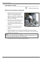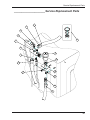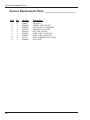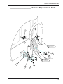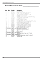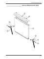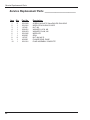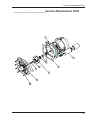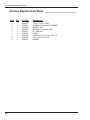
1
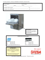
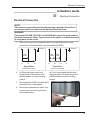
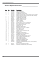
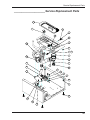
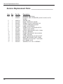
Installation Manual with Service Replacement Parts
Undercounter
High Temperature
Dishwasher
Models:
UH-200B
UH-200
UH-170B
UH-170
UH-200B
UH-100B
UH-100
UL-100
UH-170B
Dishwasher Serial No.
UH-100B
Issue Date: January, 2007
www.championindustries.com
Manual P/N 0512241
For machines beginning with S/N W11948 and above
File: NUC4246
P.O. Box 4183
Winston-Salem, NC 27115
336/661-1556 Fax: 336/661-1979
Toll-free: 800.532.8591
2674 N. Service Road, Jordan Station
Ontario, Canada L0R 1S0
905/562-4195 Fax: 905/562-4618
Toll-free: 800.263.5798
Printed in the USA
For future reference, record your dishwasher information in the box below.
Model Number__________________________ Serial Number_______________________
Voltage________________Hertz_____________ Phase__________________
Champion Service Agent __________________________________ Tel:______________________
Champion Parts Distributor _________________________________ Tel:______________________
For all models:
The data plate is located on
the bottom right-hand side of
the dishwasher.
National Service Department
In Canada:
Toll-free: 800/ 263-5798
Tel:
905/ 562-4195
Fax:
905/ 562-4618
email: [email protected]
In the USA:
Toll-free: 800/ 532-8591
Tel:
336/ 661-1556
Fax:
336/ 661-1979
email: [email protected]
ATTENTION:
We support
The dishwasher model no., serial no.,
voltage, Hz and phase are needed to
identify your machine and to answer
questions.
Please have this information on-hand
if you call for service assistance.
COPYRIGHT © 2006 All rights reserved
Printed in the USA
Revisions to this Manual
_______________________ Revisions to this Manual
This is where we record changes to the manual. A revision might be a part
number change, new instructions, or information that was not available at print
time.
We reserve the right to make changes to this manual without notice and without
incurring any liability by making the changes.
Revision
Date
1.16.07
Revised
Pages
Serial Number
Effectivity
ALL
W11948
17,19
W11948
Revision
Description
Released First Edition
Changed operation instructions
deleting step 1, which was out
of sequence
i
Limited Warranty
___________________________
ii
Model Description
___________________________ Model Description
UH-200B, UH-170B, and UH-100B Models
High temperature sanitizing dishwashers with built in booster heaters.
UH-200, UH-170, and UH-100 Models
High temperature sanitizing dishwashers.
UL-100 Model
Low temperature sanitizing dishwasher.
Optional Equipment
•
•
70°F Rise Booster
Three Phase Connection (UH-170B and UH-200B only)
iii
Table of Contents
Table of Contents ______________________________
Revisions to this manual ______________________________________________ i
Limited Warranty ____________________________________________________ ii
Model Descriptions __________________________________________________ iii
Installation Guide ____________________________________________________ 1
" Unpack and Place
" Drain Connection
" Electrical Connection
" Initial Start-up
" Water Connection
" Chemical Dispensers
How to Operate Your Dishwasher
How to Clean Your Dishwasher
How to Maintain Your Dishwasher
All Models
The Troubleshooter ________________________________________________ pg.25
Service Replacement Parts _________________________________________ pg.27
Electrical Schematics ______________________________________________ pg.67
Timer Charts _____________________________________________________ pg.73
iv
Unpack and Place
_____________________________ Installation Guide
!
Unpack and Place
Unpacking of Dishwasher
NOTE:
The installation of your dishwasher must be performed by qualiÞed service
personnel. Problems due to improper installation are not covered by the
Warranty.
1.
Inspect the outside of the dishwasher carton for signs of damage.
2.
Remove the shipping box and inspect the dishwasher for damage.
3.
Immediately contact the freight company and your equipment dealer to
report the damage.
4.
Save all packing materials.
CAUTION:
Be careful when lifting and moving the dishwasher to prevent damage to the
machine.
5.
Check your packing list and identify the accessories shipped with your
dishwasher. Immediately report missing items to your dealer.
6.
Turn to the front of this manual and complete the warranty card. Mail the
card at once.
7.
Move the dishwasher near its permanent location.
8.
Locate the Quick Check Installation Guide located on the dishwasher. Use
the card and the manual installation guide to properly install the dishwasher.
Placement of Dishwasher
CAUTION:
Be careful when lifting and moving the dishwasher to prevent damage to the
machine.
NOTE:
The installation of the dishwasher must comply with local health codes.
1.
Compare the utility connections with the dishwasher's utility connections.
Contact your supervisor if problems are found.
1
Unpack and Place
Installation Guide _____________________________
!
Unpack and Place
Placement of Dishwasher (continued)
2.
Your dishwasher may be installed as a free-standing unit or under a countertop.
3.
Typical counter-top height is 34". Refer to the illustration.
Countertop
Wall
34"
Minimum
Height
Floor
Chemical Supply
Containers
3" Minimum Wall
Clearance
Typical Undercounter Installation
2
4.
Counter installations must provide storage space for the dishwasher's
chemical supply containers. Container height must not exceed 10" above the
ßoor.
5.
Chemical supply containers must be placed as close as possible to the side of
the dishwasher.
6.
Check that the ßoor is level at the permanent location.
7.
The dishwasher has adjustable feet for leveling.
8.
Level the dishwasher front to back and side to side with a 24" bubble level to
match the permanent location.
9.
Your dishwasher is ready for the utility connections.
Electrical Connection
_____________________________ Installation Guide
!
Electrical Connection
Electrical Connection
NOTE:
The electrical connection must be performed by a qualiÞed electrician in
accordance with local codes and the National Electrical Code.
WARNING:
For models UH-100B, UH-170B, and UH-200B disconnect the main power at
the main disconnect switch. Tag and lockout the switch to indicate that work
is being done on the circuit.
1.
Refer to the connection diagrams below for proper dishwasher power
connection at the dishwasher main terminal block (MTB).
Ground
Ground
208230V
L1
120V
L2
208230V
208230V
120V
N
L1
L2
L3
Single Phase
Three Phase
3-Wire Plus Ground
4-Wire Plus Ground
2.
(a) Electrical supply must be a
single phase 3-wire plus ground
which includes a current carrying
neutral.
3.
The dishwasher MTB is located at the
front right-side of dishwasher.
4.
Remove the dishwasher's lower front
access panel by removing the two
truss head screws.
N
(b) For a three phase the electrical
supply must be a 4-wire plus ground
which includes a current carrying
neutral.
Front Panel Screw Location
3
Electrical Connection
Installation Guide _____________________________
!
Electrical Connection
Electrical Connection (continued)
5. Carefully bump the lower front access
panel up as you pull forward. Be
careful not to damage the pressure
gauge mounted on the left side of the
panel (not supplied on models UL-100,
UH-100, or UH-100B).
6.
Remove the main terminal block cover.
The machine's electrical schematic
is located on the inside of the front
panel. Check the min/max data on the
schematic.
7.
Loosen the two screws securing the
MTB. Then, pull the MTB up and
forward.
8.
Connect a ßexible power cord conduit to the MTB. The power cord must
extend a minimum of 3ft out the back of the dishwasher so the machine can
be pulled out for servicing.
Main Terminal Block (MTB)
NOTE:
Models UL-100, UH-100, UH-170, UH-200 are already equipped with a 4 foot
power cord and plug suitable for 115V-15A service.
9.
4
Re-install the MTB and the lower front access panel.
Water Connection
_____________________________ Installation Guide
!
Water Connection
Water Connection UH-170, UH-170B, UH-200, UH-200B
NOTE:
Plumbing connections must comply with national, local plumbing and
sanitary codes.
NOTE:
Route the ßexible Þll hose in a manner that prevents kinks.
1.
All models have a 6ft ßexible hot water Þll hose with a 3/4" female garden
hose connector.
2.
A 1/2" or larger shut off valve should be installed upstream from the
dishwasher.
3.
A pressure regulating valve, PRV, (supplied by others) must be installed after
the shut-off valve if incoming water pressure exceeds 20psi.
4.
The hot water supply must provide a minimum of 140°F, measured at the
dishwasher for the 40°F rise booster. For the 70°F rise booster the hot water
supply must provide a minimum of 110°F measured at the dishwasher.
5.
The incoming hot water supply line must be a 1/2" line and be able to
maintain a ßowing pressure of 20-22psi.
5
Water Connection
Installation Guide _____________________________
!
Water Connection
Water Connection UL-100, UH-100, UH-100B
NOTE:
Plumbing connections must comply with national, local plumbing and
sanitary codes.
NOTE:
Route the ßexible Þll hose in a manner that prevents kinks.
6
1.
All models have a 6ft ßexible hot water Þll hose with a 3/4" female garden
hose connector.
2.
A 1/2" or larger shut off valve should be installed upstream from the
dishwasher.
3.
All models have a built-in ßow control. The incoming hot water supply must
supply no less than 25-95psi ßowing pressure.
4.
The hot water supply must provide a minimum of 140°F, measured at the
dishwasher for the 40°F rise booster. For the 70°F rise booster the hot water
supply must provide a minimum of 110°F measured at the dishwasher.
5.
The incoming hot water supply line must be a 1/2" line.
Drain Connection
_____________________________ Installation Guide
!
Drain Connection
Drain Connection
1.
All models have a 6ft, 5/8" I.D. drain hose. Maximum drain hose height is 3ft.
with a recommended height of 17" above the ßoor.
2.
The drain hose is located on the right rear of the machine. A 5/8" hose barb 3/4" NPT adapter Þtting is strapped to the end of the drain hose for the drain
connection.
3.
The maximum drain ßow is 15gpm.
NOTE:
The dishwasher drains in 8 seconds and drain water exits the hose with
considerable force.
CAUTION:
Do not connect the drain hose to a disposer. The dishwasher will not drain
correctly.
4.
The drain hose is clamped to the rear of the machine to provide a goose
neck bend. DO NOT remove this clamp.
5.
Connect the drain hose to a wye Þtting installed in the house drain. DO NOT
connect to a tee Þtting.
6.
Do not kink the drain hose.
7
Blank Page
This Page Intentionally
Left Blank
8
Initial Start-Up
_____________________________ Installation Guide
!
Initial Start-Up
Initial Start-Up All Models
1.
Remove any protective Þlm from
dishwasher. Check the interior for
foreign material.
2.
ConÞrm that all utility connections
are complete and that the
dishwasher is in it's permanent
location.
3.
Inspect the ßexible drain hose and
hot water Þll hose to ensure they
are not kinked.
4.
Check the chemical supply
containers to ensure they are full.
5.
Check that the scrap screen and
the overßow guard (Models
UH-170, UH-170B, UH-200, and
UH-200B only) are in place.
6.
Check the spray arms are in place
and that they spin freely.
7.
Fully close the dishwasher door.
8.
Turn hot water supply on and
check for leaks.
Scrap Screen
9
Initial Start-Up
Installation Guide _____________________________
!
Initial Start-Up
Models: UH-100B, UH-170B, and UH-200B only
ATTENTION:
The Dishwasher's built-in booster heater was drained prior to
shipment. The booster must be Þlled before operating the
dishwasher. Not following this procedure will void warranty.
Booster Service Switch
The booster is Þlled with the booster service
switch. It is located behind the lower front
access panel on the left center of the
machine.
To Fill the Booster:
1.
Remove the lower front access panel.
2.
Locate the booster service switch and
note the 2 switch positions indicated
on the switch label.
3.
Turn the main power supply on. Verify
correct voltage at MTB.
4.
Press and hold the booster service
switch down to Þll the booster.
5.
Continue to hold the switch down until
you hear the water spraying inside
the dishwasher.
6.
Release the switch, then ßip the
switch up to the ON position. The
dishwasher is now powered up.
Booster Service Switch Location
Booster Service Switch Fill Position
10
Initial Start-Up
_____________________________ Installation Guide
!
Initial Start-Up
Booster Service Switch (continued)
7.
Flip the dishwasher POWER switch
up to the " I " position. The POWER
switch illuminates and the machine
Þlls with water. See Proper Water Fill
Line illustration.
8.
Press and release the START switch.
The green in-cycle light illuminates.
9.
Check wash and Þnal rinse gauges
to ensure they have reacted to the
incoming hot water.
Power Switch
10. Check that the Þnal rinse pressure
gauge reacts during the Þnal rinse.
(Models UH-170, UH-170B, UH-200,
and UH-200B only)
11. Flip the POWER switch down to the
"O" position. The green in-cycle light
stays on and begins the drain cycle.
Proper Water Fill Line
12. The green in-cycle light goes out
when the machine has drained
completely.
13. The Initial start-up is complete.
Wash and Rinse Temperature Gauge
Final Rinse Pressure Gauge
11
Chemical Dispensers
Installation Guide _____________________________
!
Chemical Dispensers
Chemical Dispensers
1.
All models come equipped with a builtin detergent dispensing pump and a
rinse-aid dispensing pump. The pumps
are located behind the lower front
access panel.
2.
Each pump is Þtted with 6ft of pickup supply tubing, a stand-pipe, and a
strainer.
3.
Pick-up tubes are marked detergent
and rinse-aid. Make sure the pickup tubes are placed in the correct
chemical supply container (chemicals
supplied by others).
4.
The chemical dispensers require nonchlorinated liquid detergent and rinseaid. Your chemical supplier must adjust
the dispensers for the supplied product.
5.
Chemical containers must be placed
as close to the dishwasher as possible
and no higher than 10" above the ßoor.
Dispenser Pump Location
Pick-Up Tubes
12
Chemical Dispensers
_____________________________ Installation Guide
!
Chemical Dispensers
How to Prime the Dispensers
1.
Place the chemical containers next to
the dishwasher.
2.
Insert the detergent and rinse-aid
pick-up tubes in the correct chemical
supply container.
3.
Open the dishwasher door.
4.
Press and hold the PRIME switch up
to prime the detergent. Watch the
detergent injection point located on
the right rear wall of the machine until
chemical enters the machine.
Prime Switch Up
Detergent Injection Point
13
Chemical Dispensers
Installation Guide _____________________________
!
Chemical Dispensers
How to Prime the Dispensers (continued)
5.
Press and hold the prime switch down
for 30 seconds to prime the rinse-aid.
6.
All chemicals enter the UL-100, UH100, and UH-100B through the Þll
chute injection point located on the
right-side of the wash compartment.
Prime Switch Down
Fill Chute Injection Point
14
Chemical Dispensers
_____________________________ Installation Guide
!
Chemical Dispensers
To Chemical Suppliers
How to Adjust Chemical Dispensers:
1.
The chemical dispensing pumps are
adjustable.
2.
Adjustments are made by turning
the trim potentiometers located
on the dishwasher control board
located at the lower right corner of
the machine.
3.
Remove the lower front access
panel and identify the control circuit
board cover. Each dispensing trim
potentiometer is labeled on the
cover.
4.
Trim potentiometers are adjusted
using a small screwdriver inserted
Trim Potentiometer Location
into the adjusting slot. Turning the
screwdriver clockwise increases the amount of dispensed chemical; counter
clockwise reduces the amount of chemical dispensed.
15
Blank Page
This Page Intentionally
Left Blank
16
Operation
Models UH-170, UH-170B, UH-200, and UH-200B
UH-170B Control Panel
UH-200B Control Panel
Normal Wash Cycle
1.
Flip the POWER switch up to the " I " position. The switch illuminates, water
enters the wash compartment. Wash tank heater heats wash water and the
booster heater begins to heat the final rinse water.
2.
Prescrap and load wares into the appropriate dishrack.
NOTE:
Do not overload dishrack. Load wares in a peg rack; load silverware in a
single layer in a flat-bottom dishrack. Overloading dishrack will result in
poor washing results.
NOTE:
Wash temperature gauge must read 150°F before proceeding to the next
step.
3.
Open dishwasher door and slide dishrack into the machine. Only wash one
dishrack per wash cycle.
4.
Close dishwasher door and press the START switch for 1 second. The
green in-cycle light illuminates and the wash cycle begins.
NOTE:
Opening the door stops the cycle. When the dishwasher door is closed the
cycle resumes automatically.
17
Operation ___________________________________
Normal Wash Cycle (continued)
6.
Check the rinse cycle temperature gauge during the Þnal rinse cycle to
ensure the Þnal rinse temperature ranges between 180°-195°F.
7.
Machine drains wash water and holds Þnal rinse water for the next wash
cycle. The green in-cycle light goes out completing the cycle.
8.
Open the dishwasher door and remove the dishrack of clean wares.
9.
Repeat steps 2-8 for additional cycles.
NOTE:
Poor washing results will occur if the scrap screen is not cleaned regularly.
Extended Wash Cycle
The extended wash cycle is ideal for pots, pans, and heavily soiled items.
1.
Follow STEPS 1-5 of the Normal Wash Cycle.
2.
Wait 10 seconds to allow detergent to enter into the dishwasher.
3.
Press the EXT WASH switch. The light above the EXT WASH switch
illuminates, indicating that the dishwasher is in a continuous extended wash
mode.
4.
Press the EXT WASH switch again to take the dishwasher out of the
extended wash mode. The light above the EXT WASH switch goes out but
the green light above the START switch will stay illuminated, indicating the
dishwasher has resumed the remainder of the wash cycle.
NOTE:
The dishwasher washes until the extended wash cycle switch is pressed to
stop the extended wash mode, or for a maximum of 15 minutes.
18
Operation
Models UL-100, UH-100, and UH-100B
UL-100, UH-100, and UH-100B Control Panel
Normal Wash Cycle
1.
Flip the POWER switch up to the " I " position. The switch illuminates, water
enters the wash tank. Wash tank heater heats wash water and the booster
heater begins to heat the final rinse water.
2.
Prescrap and load wares into the appropriate dishrack.
NOTE:
Do not overload dishrack. Load wares in a peg rack; load silverware in a
single layer in a flat-bottom dishrack. Overloading dishrack will result in
poor washing results.
NOTE:
Wash temperature gauge must read 150°F before proceeding to the next
step. (140°F for UL-100).
3.
Open dishwasher door and slide dishrack into the machine. Only wash one
dishrack per wash cycle.
4.
Close dishwasher door and press the START switch for 1 second. The
green in-cycle light illuminates and the wash cycle begins.
NOTE:
Opening the door stops the cycle. When the dishwasher door is closed the
cycle resumes automatically.
19
Operation ___________________________________
Normal Wash Cycle (continued)
6.
Check that the temperature gauge reads 180°F (140°F on UL-100) during the
rinse cycle.
7.
Machine drains and holds Þnal rinse water for the next wash cycle. The green
in-cycle light goes out completing the wash cycle.
8.
Open the dishwasher door and remove the dishrack of clean wares.
9.
Repeat steps 2-8 for additional cycles.
NOTE:
Poor washing results will occur if the scrap screen is not cleaned regularly.
20
How to Clean Your Dishwasher
___________________________________ Cleaning
The best preventative maintenance is to keep the dishwasher as clean as possible
during regular use and ensure best results. A regular cleaning schedule will
increase the life of the dishwasher.
CAUTION:
Damage to the unit or improper operation may occur if components are not
ßushed and cleaned on a regular scheduled basis.
Daily-End of the Day
1.
Flip the POWER switch to the "O" position and close the door to drain the
tank. The green in-cycle light will illuminate indicating the machine is in the
drain out cycle. This will last 90 seconds.
2.
After the green in-cycle light goes
out, open the door and remove both
the upper and lower spray arms by
unscrewing the knurled fastener while
holding each spray arm.
3.
Remove the scrap screen carefully to
keep the soil or waste particles from
falling into the sump.
4.
Clean the scrap screen by rinsing with
clean water. Do not strike the screen
against solid objects.
Spray Arm Fastener
Sump Location
21
How to Clean Your Dishwasher
Cleaning ____________________________________
Daily-End of the Day (continued)
5.
Clean the spray arms to remove any
debris from spray nozzles. Do not
strike the spray arms against solid
objects.
6.
Reinstall the scrap screen.
7.
Wipe the exterior of the dishwasher
clean using a soft cloth and mild
detergent.
8.
Leave the dishwasher door open
overnight to allow the inside to dry.
Spray Nozzle
After Meal Period or Every 8 Hours
Clean the scrap screen after each meal period and more frequently if necessary in
order to keep the scrap screen from becoming clogged.
Deliming
Your dishwasher should be delimed regularly. The frequency will depend on the
mineral content of your water.
Inspect your machine interior for lime deposits. If deliming is required, a deliming
agent should be used for best results.
DANGER:
Deliming solution or other acids must not come in contact with household
bleach (sodium hypochlorite) or any chemicals containing chlorine, iodine,
bromine, or ßuorine. Mixing will cause hazardous gases to form. Skin contact
with deliming solutions can cause severe irritation and possible chemical
burns. Consult your chemical supplier for speciÞc safety precautions.
22
How to Maintain Your Dishwasher
________________________________ Maintenance
Maintenance Schedule
The best maintenance you can perform is to keep your dishwasher clean.
Before and During Operation
•
Check the temperature gauges during operation to ensure the proper
temperatures are maintained.
•
Check the chemical supply container level and replace if necessary.
Weekly Maintenance
•
Inspect all water lines for leaks.
•
Check drain for leaks.
•
Clean accumulated lime deposits from the heating element.
•
Inspect each spray arm for clogged nozzles.
•
Check the scrap screen for damage and cleanliness.
Clean the detergent and rinse-aid pick-up tubes by following the steps
below:
1.
Remove the detergent and rinse-aid (add sanitizer on UL-100 model) pickup tubes from each container. Place the pick-up tubes in separate containers
of hot water.
2.
Press and hold the PRIME switch in the "UP" position to ßush the detergent
tubing and in the "DOWN" position to ßush the rinse-aid tubing.
3.
Remove the pick-up tubes from the hot water and return them to their
chemical containers.
4.
Press and hold the PRIME switch in the "UP" position to Þll the detergent
tubing and in the "DOWN" position to Þll the rinse-aid tubing.
5.
Run a complete wash cycle to ßush any chemicals out of the wash
compartment.
23
Blank Page
This Page Intentionally
Left Blank
24
The Troubleshooter
The Troubleshooter
25
The Troubleshooter
Troubleshooter _______________________________
CONDITION
SOLUTION
Door not closed.
Clear door of any obstructions.
Main switch is off.
Check disconnect or main circuit.
Unit is unplugged.
Plug unit back into wall outlet.
Low or no water.
Main water supply is
turned off.
Turn on house water supply.
Chemicals are not entering
dishwasher.
Chemical supply container
is low or empty.
Replace or Þll chemical supply
container.
Pick-up tubing is kinked
or split.
Straighten or replace tubing.
Screen on pick-up tube is
clogged.
Clean and/or replace screen.
Pick-up tubing is clogged.
Clear obstruction and ßush with
hot water.
Clogged spray arms or
nozzles.
Clear obstruction and ßush with
hot water.
Clogged scrap screen.
Clean and/or replace screen.
Detergent pick-up tube in
wrong container.
Place pick-up tube into the
correct container.
Wash water temperature
too low.
Have wash thermostat adjusted
by service agent.
Wares incorrectly loaded
in rack.
Use correct racks and load
dishes without nesting.
No detergent.
Replace/reÞll detergent container.
Detergent set too low.
Have chemical representative
calibrate setting.
Incoming water
temperature too low.
Raise incoming water
temperature.
Machine will not start.
Poor pumped spray
pressure.
Poor wash results.
Cycle times increasing
with each load.
26
CAUSE
Service Replacement Parts
Service Replacement
Parts
27
Service Replacement Parts
Service Replacement Parts _____________________
28
Item
Qty
Part No.
Description
1
2
3
4
1
1
1
1
5
6
7
8
9
10
11
12
13
14
15
16
17
18
19
20
21
22
23
24
25
26
27
28
29
1
1
1
1
1
1
2
2
1
2
1
4
4
1
1
1
1
2
1
4
1
1
1
1
1
1
0712236
0712136
0507323
0512169
0512168
D500615
109069
D80208
D500603
D80305
108447
0512322
0512185
0512227
0512352
0312145
0501501
0501539
0503718
0501411
0501379
0312096
112612
0312144
0502571
0512132
0512118
0512119
110562
0508872
0512299
30
31
2
1
201029
0508873
TUBE, OVERFLOW
SCREEN, SCRAP ASSY
THERMOSTAT, WASH TANK
HEATER, 120VAC 750W (UL100, UH100, UH170, UH200)
HEATER, 230VAC 1200W (UH100B, UH170B, UH200B)
FLANGE, PUMP SUCTION
THERMOSTAT, BOOSTER
GASKET, PUMP SUCTION
ELBOW, PUMP SUCTION
GASKET, ELBOW
CAP, 1 1/4 PLASTIC
CLAMP, HOSE 1-13/16 - 2-3/4 MAX S/S
BOLT, HEX FLANGE 1/4-20 X 3/8 SS
PUMP, DRAIN 115V 60 HZ.
SCREW, #10 x 3/4
BRACKET, DRAIN PUMP
WASHER, SPLIT LOCK 1/4i 304SS
NUT, HEX SS 1/4-20
FOOT, ADJUSTING
SCREW, 10-32 X 1/4 RH SLOT SS
SWITCH, 15A
BRACKET, DOOR SWITCH
THERMISTOR, 10k 2 WIRE ASSY
BRACKET, WASH PUMP
CLAMP, HOSE GEAR HOSE 1-1/2” SS
HOSE, OVERFLOW MOLDED FWR
HOSE, PUMP SUCTION
HOSE, PUMP DISCHARGE
THERMOSTAT, BIMETAL SNAP
ADAPTOR, THERMOMETER
ADAPTOR, THERMOMETER (UH170, UH170B, UH200,
UH200B ONLY)
NUT, LOCK 1/2 INCH NI PLATED
ADAPTOR, THERMOSTAT (NOT SHOWN)
Service Replacement Parts
_____________________ Service Replacement Parts
2
1
29
3
30
4
5
27
28
6
22
7
26
8
9
25
11
24
10
12
23
13
14
15
16
17
18
21
20
19
29
Service Replacement Parts
Service Replacement Parts _____________________
30
Item
Qty
Part No.
Description
1
3
1
107964
0503647
2
3
4
5
6
7
8
9
10
11
12
13
14
15
16
17
1
1
1
1
1
1
1
1
1
1
1
1
1
1
1
1
0508710
0312188
0501411
0312189
0512243
106695
0512105
0312339
0504951
0501412
0503592
0501403
0312338
0501493
0501533
0501472
BUSHING, SNAP (ALL)
BUSHING, MED. STRAIN REL (UL100, UH100, UH170,
UH200)
SPACER, 5/16
BASE, TIMER ENCLOSURE
SCREW, 10-32 X 1/4 RH SLOT SS
COVER, TIMER ENCLOSURE
LABEL, ADJUSTMENT
SCREW, 6-32 X 1/2 ROUND HD PHI
TIMER, SOLID STATE
COVER ,ENCLOSURE, ELEC. CONN
BLOCK, TERMINAL
SCREW TRUSS SLOT SS 10-32X3/8
LABEL, GROUND
SCREW, BRASS RH 10-32X3/4 SLOT
BASE, ENCLOSURE, ELEC. CONN
WASHER LOCK #10 EXT. TOOTH BR
NUT, BRASS 10-32
WASHER, FLAT 1/8 X 1/2 BRASS
Service Replacement Parts
_____________________ Service Replacement Parts
1
2
3
4
5
6
7
8
9
16
17
15
11
14
13
12
11
10
31
Service Replacement Parts
Service Replacement Parts _____________________
32
Item
Qty
1
2
3
4
5
6
7
8
9
10
1
1
4
1
2
1
1
2
1
1
Part No.
Description
0312173
0507323
0504822
0501373-1
0501412
109069
107369
0501412
0510648-1
0501450
BRACKET, CHEM PMP/THERMO CTRL
THERMOSTAT, WASH TANK
SCREW, 8-32 X 1/2 PAN HD PH S.S
SWITCH, 3-POST TOGGLE W/KEYWAY
SCREW, 10-32 X 3/8 PAN HD PH S.S
THERMOSTAT, BOOSTER
CONTACTOR, 2-POLE 120V
SCREW, TRUSS SLOT SS 10-32 X 3/8
LABEL, SWITCH
SCREW, NIBS RH 6-32 X 3/16 PHIL.SS
Service Replacement Parts
_____________________ Service Replacement Parts
9
4
1
7
5
8
TO
WA
S
HT
AN
K
TO
BO
OS
TE
R
2
6
10
3
33
Service Replacement Parts
Service Replacement Parts _____________________
34
Item
Qty
Part No.
Description
1
2
3
4
5
6
7
8
9
10
11
12
13
14
9’
6
1
1
1
3
1
2
1
1
2
1
1
1
107417
0503679
112728
0508817
112646
112883
112763
0501539
100500
0312190
0501501
201029
0502651
900836
HOSE, RUBBER 1/2ID X .84OD
CLAMP, SS GEAR-MIN. 5/16-MAX.7/8
FITT COMP 1/4OD X 1/8MPT ELL J
PLUG, 1/8 HEX COUNTERSUNK
MANIFOLD, RINSE FWR
TUBING, 1/8OD X 1/16 ID PE.
INJECTOR FITTING
NUT, HEX SS 1/4-20
VACUUM BREAKER, 1/2i BRASS
BRACKET, VACUUM BREAKER
WASHER, SPLIT LOCK 1/4i 304SS (NOT SHOWN)
NUT, LOCK 1/2 INCH NI PLATED
COUPLER 1/2 MPT X 1/2 HOSE
REPAIR KIT FOR ITEM 9
Service Replacement Parts
_____________________ Service Replacement Parts
2
1
3
4
14
5
6
9
7
12
2
10
8
11
13
2
35
Service Replacement Parts
Service Replacement Parts _____________________
36
Item
Qty
Part No.
Description
1
2
3
4
5
6
7
8
9
2
1
1
4
6
1
1
5’
1
106090
0509048
0508867
0507709
0503722
0502666
0502667
107417
0308822
TIE PLATE
GASKET, INLET CHUTE
CHUTE, INLET INJ.MOLDED
WASHER, FLAT #10 SS
NUT, HEX 10-32 SS
HOSE, 1/8ID X 1/4OD PVC
HOSE, 1/4ID X 3/8OD PVC
HOSE, RUBBER 1/2ID X .84OD
CLIP, HOSE
Service Replacement Parts
_____________________ Service Replacement Parts
1
1
5
5
8
FROM TOP OF BOOSTER
OR FILL V ALVE
9
5
7
6
2
3
FROM RINSE AID
PUMP
FROM DETERGENT AND
SANITIZER PUMPS
5
4
37
Service Replacement Parts
Service Replacement Parts _____________________
Item
1
2
3
4
5
Qty
Part No.
Description
1
0509042
BOOSTER TANK
2
0512185
BOLT, HEX FLANGE 1/4-20 X 3/8 SS
1
0508817
PLUG, 1/8 HEX COUNTERSUNK
1
109985
SEAL, ELECTRIC HEATER FLANGE
1
111235
HEATER 5/6.6KW 208/240V
1
111233
HEATER 7.5/10KW 208/240 (70 DEGREE RISE)
6
1
H161123
COVER,HEATING ELEMENT
7
6
0501539
NUT, HEX SS 1/4-20
8
1
109069
THERMOSTAT, BOOSTER
9
3
0501501
WASHER, SPLIT LOCK 1/4i 304SS (NOT SHOWN)
10
2
108954
NUT, GRIP 6X32 NYLON INSERT SS
11
1
110562
THERMOSTAT, BIMETAL SNAP
12
2
0508840
BUSHING, 3/4MPT X 3/8FPT BRASS
13
2
0502653
ELBOW, 90 DEGR 3/8MPTX1/2 HOSE
14
6
0503679
CLAMP, SS GEAR-MIN. 5/16-MAX.7/8
15
9’
107417
HOSE, RUBBER 1/2ID X .84OD
FOR MODELS UH170, UH170B, UH200, UH200B ONLY
16
1
0572297
COUPLER, 1/2 HOSE X 3/4 NPT
17
1
102525
TEE
18
1
100184
NIPPLE 3/4 NPT
FOR MODELS UH170, UH170B ONLY
19
1
0512107
THERMOMETER, 2" DIAL C/W 7FT CAP
FOR MODELS UH200, UH200B ONLY
20
1
0512298
BUSHING REDUCING 1/8" NPT X 1/2" NPT
21
1
112612
THERMISTER
38
Service Replacement Parts
_____________________ Service Replacement Parts
14
15
13
12
11
10
8
1
2
15
14
3
16
4
5
17
6
18
14
7
13
19
12
15
20
21
39
Service Replacement Parts
Service Replacement Parts _____________________
40
Item
Qty
Part No.
Description
1
2
3
4
5
6
7
8
9
10
11
1
2
2
1
1
1
1
1
1
1
1
0502653
0502650
0512185
109886
108516
109902
0502651
0503679
0509526
107873
0312146
ELBOW, 90 DEGR 3/8MPTX1/2 HOSE
BUSHING, 1/2 X 3/8
BOLT, HEX FLANGE 1/4-20 X 3/8 SS
VALVE, 1/2” NPT 120V
COIL REPAIR KIT
REPAIR KIT
COUPLER 1/2 MPT X 1/2 HOSE
CLAMP, SS GEAR-MIN. 5/16-MAX.7/8
HOSE, 1/2 X 7FT FEM.GARD.ADAPT.
WASHER, PACKING
BRACKET, VALVE FWR
Service Replacement Parts
_____________________ Service Replacement Parts
W
5
N
TIO
EC
NN
CO
6
TO B
OOS
TER
OR F
ILL
4
A
R
TE
10
9
8
7
3
8
1
2
11
41
Service Replacement Parts
Service Replacement Parts _____________________
42
Item
Qty
Part No.
Description
1
2
3
4
5
6
7
8
9
1
4
1
1
1
1
1
1
1
0502653
0512185
0300065
0300203
0502618
0503679
0509526
505320
0504952
ELBOW, 90 DEGR 3/8MPTX1/2 HOSE
BOLT, HEX FLANGE 1/4-20 X 3/8 SS
SUPPORT, VALVE
CLAMP, VALVE
HOSE BARB, 1/2 X 3/8 MPT
CLAMP, SS GEAR-MIN. 5/16-MAX.7/8
HOSE, 1/2 X 7FT FEM.GARD.ADAPT.
WASHER, 1” O.D. GARDEN HOSE
VALVE
Service Replacement Parts
_____________________ Service Replacement Parts
W
AT
ION
CT
NE
ON
C
ER
8
7
6
5
2
9
4
TO BOOSTER OR FILL
1
3
2
6
2
43
Service Replacement Parts
Service Replacement Parts _____________________
44
Item
Qty
Part No.
Description
1
2
3
4
5
6
7
8
9
10
11
12
13
14
15
16
17
18
19
20
21
22
23
24
25
26
27
28
29
30
4
4
1
1
1
2
1
2
4
2
2
2
1
1
1
1
1
1
2
1
1
1
1
1
1
2
1
4
4
2
0501478
107967
H35509
107873
110215
0502571
0512120
112550
112551
0512129
112549
H420548
0512133
100194
0512104
0512126
0512130
0512128
104883
0512123
0512127
0501412
0512103
0512066
0512125
H420548
0512133
0501481
0501420
H420548
WASHER, 17/64IDX9/16 OD18G SS
NUT, HEX SS 1/4-20 NYLON INSERT
HUB,UPPER WASH ARM
WASHER, PACKING
SCREW, RETAINING
CLAMP,HOSE GEAR HOSE 1-1/2” SS
HOSE, UPPER WASH ARM,
LOCKNUT, WASH ARM
BEARING, WASH ARM
NUT, WASH ARM F&D (UL100, UH100, UH100B)
HUB, WASH ARM
ASSY, WASH ARM COMPLETE (NOT SHOWN)
O RING, 2 1/8 OD X 1 3/4 ID X 3/16 #327 SILICONE
NUT, GRIP 10-32
FLAP, DRAIN
SPRING, TORSION
O RING #106
SHAFT, DRAIN FLAP
SCREW 6-32 X 3/8 RD HD SS-SLOT
MOTOR, DRAIN 115V
GASKET, DRAIN
SCREW TRUSS SLOT SS 10-32X3/8
MANIFOLD, LOWER F&D (UL100, UH100, UH100B)
HUB, LOWER WASHARM
SHAFT, LOWER F&D (UL100, UH100, UH100B)
WASH ARM, STAMPED
O RING, 2 1/8 OD X 1 3/4 ID X 3/16 #327 SILICONE
WASHER, NYLTITE
BOLT, 1/4 X 1i SS HEX HEAD
WASH ARM ASSEMBLY INCLUDES ITEMS 8, 9, 11, 26
Service Replacement Parts
_____________________ Service Replacement Parts
5
6
4
7
3
2
1
28
26
29
27
8
9
11
9
10
9
8
11
9
26
25
13
24
6
23
14
22
15
21
16
20
17
18
19
45
Service Replacement Parts
Service Replacement Parts _____________________
46
Item
Qty
Part No.
Description
1
2
3
4
5
6
7
2
2
12
4
2
1
1
H34998
H36211
H37149
H190663
H36275
0512124
0512102
8
2
H36211
NUT, SPACER
RINSE ARM
NOZZLE, 65L/HR S.S.
BUSHING, RINSE ARM
PIN, RINSE ARM
SHAFT, LOWER FWR (UH170, UH170B, UH200, UH200B)
MANIFOLD, LOWER FWR (UH170, UH170B, UH200,
UH200B)
RINSE ARM COMPLETE (NOT SHOWN)
Service Replacement Parts
_____________________ Service Replacement Parts
1
2
3
4
5
6
7
47
Service Replacement Parts
Service Replacement Parts _____________________
48
Item
Qty
1
2
3
4
5
6
7
8
9
10
1
1
1
1
1
4
12
1
1
1
Part No.
Description
0510870-1
114203
114202
0501519
0502644
0501519
0502667
0503695
0306363
0501869
GEARMOTOR,108 RPM, 115/60/1
PUMP HD KIT, PERISTALIC
TUBE ASY,SANTOPRENE,1/4IDX8.25
TIE, NYLON 4i
ELBOW, 1/4 HOSE BARB
TIE, NYLON 4i
HOSE, 1/4ID X 3/8OD PVC
LABEL, DETERGENT
TUBE,1/2IDX11-7/8LG. STIFFENER
STRAINER
Service Replacement Parts
_____________________ Service Replacement Parts
Detergent Pump All Models
2
1
3
4
5
6
7
8
9
10
49
Service Replacement Parts
Service Replacement Parts _____________________
50
Item
Qty
Part No.
Description
1
2
3
4
5
6
7
8
9
10
1
1
1
2
1
1
1
2
2
1
0503756
0706635
0707142
0501519
0505483
0306363
0501869
0504822
0506589
0502666
MOTOR, INJECTOR PUMP
TUBE, ELEMENT ASSEMBLY 45CC
ROTOR, ASSEMBLY
TIE, NYLON 4i
LABEL, RINSE AID
TUBE,1/2IDX11-7/8LG. STIFFENER
STRAINER
SCREW, 8-32 X 1/2 PAN HD PH S.S
SCREW, PAN 6-32X7/8 SS PHILLIP
HOSE, 1/8ID X 1/4OD PVC
Service Replacement Parts
_____________________ Service Replacement Parts
Rinse Aid/Sanitizer Pump
1
8
2
3
4
9
10
5
6
7
51
Service Replacement Parts
Service Replacement Parts _____________________
Item
Qty
Part No.
Description
1
1
1
2
1
1
1
1
1
1
1
1
1
1
1
2
1
4
2
2
0512220
0512221
0512232
0512226
0501408
0512110
0512111
051212
0312178
0312179
0312180
0512214
0512107
0512215
0512213
0512106
0501563
0503580
0512357
SWITCH, ROCKER DPDT 125V NEON (UL100 ONLY)
SWITCH, ROCKER DPDT 250V NEON
LIGHT, INDICATOR, GREEN LED 2VDC
SWITCH, ROCKER RND SPDT MOMENTARY
SCREW, TRUSS SLOT SS 8-32 X 1/4
LABEL, FACIA, UH200
LABEL, FACIA, UH170
LABEL, FACIA, UH100
PANEL, FACIA, UH200
PANEL, FACIA, UH170
PANEL, FACIA, UH100
SWITCH, PUSHBUTTON, GREEN
THERMOMETER, 2” DIAL C/W 7’ CAPILARY
SWITCH, PUSHBUTTON, WHITE
SWITCH, PIE ZIO
THERMOMETER, DIGITAL
SCREW, #8 x 3/8
NUT, 10-32
SPACER
2
3
4
5
6
7
8
9
10
11
12
13
14
52
Service Replacement Parts
_____________________ Service Replacement Parts
Models UL-100, UH-100, and UH-100B
8
3
2
7
6
1
5
4
53
Service Replacement Parts
Service Replacement Parts _____________________
Models UH-170 and UH-170B
8
9
3
2
7
6
1
5
4
54
Service Replacement Parts
_____________________ Service Replacement Parts
Models UH-200 and UH-200B
14
13
11
12
2
10
3
1
5
6
4
55
Service Replacement Parts
Service Replacement Parts _____________________
56
Item
Qty
Part No.
Description
1
1
1
109812
0512107
2
3
4
5
6
7
8
9
10
11
12
13
1
2
2
1
2
1
1
4
4
1
1
1
0312192
100779
108826
0312174
0501412
0312191
0712209
0501478
0501539
0312175
107928
112728
GAUGE, PRESSURE 0-60PSI
THERMOMETER, 2" DIAL C/W 7' CAP. (UL100, UH100,
UH100B)
PANEL, FRONT CHAMPION
SCREW 1/4-20X5/8 TRUSS SS PHIL
GROMMET
PANEL, RH SIDE
SCREW TRUSS SLOT SS 10-32X3/8
PANEL, BACK
HOOD, WELDED CHAMPION
WASHER, 17/64IDX9/16 OD18G SS
NUT, HEX SS 1/4-20
PANEL, LH SIDE
TUBING, 1/4i NATURAL
FITT COMP 1/4OD X 1/8MPT ELL J
Service Replacement Parts
_____________________ Service Replacement Parts
10
6
9
8
11
6
7
6
4
13
6
12
1
5
3
2
4
3
57
Service Replacement Parts
Service Replacement Parts _____________________
58
Item
Qty
1
2
3
4
5
6
7
8
1
2
1
1
1
1
2
1
Part No.
Description
0312172
0501408
0712164
0712162-1
0501476
0501422
0512122
0712162
HANDLE, DOOR CHAMPION
SCREW, TRUSS SLOT SS 8-32 X 1/4
DOOR WELDED ASSY
HINGE, RH ASSY
WASHER,SS 9/32 X 5/8 OD
BOLT, HEX SS 1/4-20 X 1-1/2
SPRING, DOOR
HINGE, LH ASSY
Service Replacement Parts
_____________________ Service Replacement Parts
1
2
8
3
7
4
5
6
59
Service Replacement Parts
Service Replacement Parts _____________________
60
Item
Qty
Part No.
Description
1
2
3
4
5
6
7
8
9
10
9
1
1
1
1
1
1
9
1
1
0512340
0512341
107435
0501501
0501478
0512345
H36355
107337
H36356
0512101
SCREW, M4.0x0.70 30mmPHILIPS PAN HEAD
IMPELLER HOUSING COVER
NUT, M6
WASHER, LOCK, M6
WASHER, PLAIN, M6
IMPELLER
SEAL
NUT, M4.0x0.70
FLANGE REAR, PUMP
PUMP ASSEMBLY COMPLETE
Service Replacement Parts
_____________________ Service Replacement Parts
8
10
7
5
9
4
3
6
2
1
61
Service Replacement Parts
Service Replacement Parts _____________________
62
Item
Qty
Part No.
Description
1
2
3
4
5
6
7
8
9
1
1
1
1
1
1
3
1
1
0504952
0502803
0502804
0504958
0502811
0505229
0501406
0505235
0502807
VALVE, FILL 5.0 GPMSCREEN, SOL-VALVE STRAINER
GASKET, CAP
WASHER, FLOW 5.0 GPM
KIT, REBUILD
GUIDE
SCREW, SLOT SS RH 8-32 X 1/2
COIL, 115V 60HZ 10W
GASKET
Service Replacement Parts
_____________________ Service Replacement Parts
Models UL-100, UH-100, and UH-100B
8
7
9
6
5
3
4
1
2
63
Service Replacement Parts
Service Replacement Parts _____________________
64
Item
Qty
1
2
3
4
5
6
7
8
1
1
1
2
1
4
12
2
Part No.
Description
0510872-1
0512325
112759
112883
0505483
0306363
0501869
0501519
GEARMOTOR,14 RPM,115/60/1
PUMP HEAD, PERISTALTIC RINSE (PINK ROLLERS)
TUBE 1/8ID X 9i PUMP
TUBING, 1/8OD X 1/16 ID PE.
LABEL, RINSE AID
TUBE,1/2IDX11-7/8LG. STIFFENER
STRAINER
TIE, NYLON 4i
Service Replacement Parts
_____________________ Service Replacement Parts
Rinse Aid Pump Models
UH-170, UH-170B, UH-200,
and UH-200B
2
1
3
8
4
5
6
7
65
Blank Page
This Page Intentionally
Left Blank
66
Electrical Schematics
Electrical Schematics
67
Electrical Schematics
68
Electrical Schematics
69
Electrical Schematics
70
Electrical Schematics
71
Blank Page
This Page Intentionally
Left Blank
72
Timer Charts
Timer Charts
73
Timer Charts
74