1
OPERATOR'S MANUAL
l,WESTERBEKE
BCD 4.4KW and BCD 6.0KW
MARINE DIESEL
GENERATOR SETS
Publication # 37144
Edition Two
May 1988
j'-.v- 'WESTERBEKE
WESTERBEKECORPORATION
MYLES STANDISH INDUSTRIAL PARK
150 JOHN HANCOCK ROAD, TAUNTON, MA 02780-7319
SAFETY PRECAUTIONS
The following symbols appear in this manual to call attention
to and emphasize conditions potentially dangerous to the
operator.
•
Use Extreme Care When Handling Engine Fuel
(A constant danger of explosion or fire exists)
Do not fill fuel tank(s) while the engine is running.
Do not smoke or use an open flame near the engine or the
fuel tank.
IWARNINGI
The above symbol is used in the manual to warn of possible
serious personal injury or loss of life.
•
DQ Not Alter or ModifY the Fuel System
Be sure all fuel supplies have a positive shut-off valve.
CAUTION
•
Be certain fuel line fittings are adequately tightened and
.free of leaks.
The above symbol is used in the manual to caution personnel
of possible damage to equipment.
Read the manual carefully and thoroughly before attempting
to operate the equipment. Know when dangerous conditions
can exist and take necessary precautions to protect personnel
and equipment.
Fuels, exhaust gases, batteries, electrical equipment, and
moving and hot parts are potential hazards that could result in
serious personal injury or death. Follow recommended procedures carefully.
•
•
Lead acid batteries emit hydrogen, a highly-explosive gas,
which can be ignited by electrical arcing or by a lighted
cigarette, cigar, or pipe. Do not smoke or allow an open
flame near the battery being serviced. Shut off all electrical equipment in the viCinity to prevent electrical arcing
during serviCing.
prevent Electric Shock
Shut off electric power before accessing electrical equipment.
Use insulated mats whenever working on electrical equipment.
Make sure your clothing is dry, not damp (particularly
shoes), and keep your skin surfaces dry when handling
electrical equipment.
Remove wristwatch and jewelry when working on electrical equipment.
Do not connect utility shore power to vessel's AC circuits,
except through a ship-to-shore double-throw transfer
switch. Damage to vessel's AC generator may result if this
is not done.
Be extremely careful when working on electrical components. High voltage can cause injury or death.
•
Exhaust Gases Are Toxic
Use Extreme Care When Servicing Batteries
Wear rubber gloves, a rubber apron, and eye protection
when servicing batteries.
Always operate bilge blowers for at least five minutes before
starting a gasoline-fueled engine; ensure no gaSOline fumes are
present before starting.
•
Make sure a fire extinguisher is installed nearby and is
properly maintained. Be familiar with its proper use. Extinguishers rated ABC by the NFPA are appropriate for all
applications encountered in this environment.
•
Avoid Moving parts
Do not service the unit while the unit is running; if a situation arises in which it is absolutely necessary to make
operating adjustments, use extreme care to avoid moving
parts and hot exhaust system components.
Do not wear loose clothing or jewelry when servicing
equipment; avoid wearing loose jackets, shirts or sleeves,
rings, necklaces, or bracelets that might be caught in
moving parts.
Make sure all attaching hardware is properly tightened.
Keep protective shields and guards in their respective
place at all times.
Do not check fluid levels or the drive-belt's tension while
the unit is operating.
Do not work on the equipment when mentally or physically incapacitated by fatigue.
Ensure thatthe exhaust system is adequate to expel gases
discharged from the engine. Check exhaust system
regularly for leaks and make sure the exhaust manifolds
are securely attached and no warping exists.
Be sure the unit and its surroundings are well-ventilated.
CALIFORNIA
Proposition 65. Warning
Diesel qine exhaust and some of its
constituents are known te,~e State
of California·to cause can~birth
defects, and other reprodu«t~
harm.
,
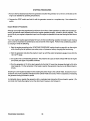
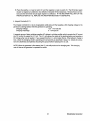
IMPORTANT
PRODUCT SOFTWARE DISCLAIMER
Product software of all kinds, such as brochures, drawings, technical data, operator's and workshop manuals,
parts lists and parts price lists, and other information, instructions and specifications provided from sources
other than Westerbeke, is not within Westerbeke's control and, accordingly, is provided to Westerbeke customers only as a courtesy and service. Westerbeke cannot be responsible for the content of such
software, makes no warranties or representations with respect thereto, including the accuracy, timeliness or completeness thereof, and will in no event be liable for any type of damages or injury incurred
in connection with, or ariSing out of, the furnishing or use of such software.
For example, components and subassemblies incorporated in Westerbeke's products and supplied by others
(such as engine blocks, fuel systems and components, transmissions, electrical components, pumps and
other products) are generally supported by their manufacturers with their own software, and Westerbeke
must depend on such software for the design of Westerbeke's own product software. Such software may
be outdated and no longer accurate. Routine changes made by Westerbeke's suppliers, of which Westerbeke rarely has notice in advance, are frequently not reflected in the supplier's software until after such changes take place.
Westerbeke customers should also keep in mind the time span between printings of Westerbeke product
software, and the unavoidable existence of earlier, non-current Westerbeke software editions in the field. Additionally, most Westerbeke products include customer-requested special features that frequently do not include complete documentation.
In summation, product software provided with Westerbeke products, whether from Westerbeke or other suppliers, must not and cannot be relied upon exclusively as the definitive authority on the respective product.
It not only makes good sense but is imperative that appropriate representatives of Westerbeke or the supplier in question be consulted to determine the accuracy and currency of the product software being consulted by the customer.
1
Westerbeke Generators
FOREWORD
Thank you for selecting a Westerbeke marine product for your use. We at Westerbeke are pleased to have
you as a customer.
Read this manual carefully and observe all safety precautions included throughout. Operating procedures,
periodic preventive maintenance procedures, installation checks, system descriptions and minor adjustment procedures are included herein so you can operate your equipment safely and properly, maintain the
equipment at a high level of efficiency, and expect dependable performance and long service life in return.
Should your unit require special attention, contact your Westerbeke dealer for assistance. The Westerbeke
Service Organization is trained to provide the support necessary to ensure long-term dependable performance.
If, within 60 days of submitting the Warranty Registration Form for your unit, you have not received a Customer Identification Card (see below) registering your warranty, please contact the factory in writing with
Model information, including the unit's serial number and commission date.
from:
WESTERBEKE CORPORATION
AVON INDUSTRIAL PARK
AVON, MA 02322
--
r,~.
•
WESTERBEKE
IIUOfII
......,..~
.,....x:
, . . . . II"''''
n_
..,
,7J •••
.1II:1z:;r: • 1'&" . .
-yy_
11; CUP) " ' - ' . 2 3 · C•• La: ••an:OIJ'
,1.-...... ...
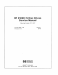
CUSTOMER IDENTIFICATION
Adam Silith
85 Maple Street
Alden, IN 12234
Mall To:
Model BCD 4.4 KW
Expires 717/89
.....
Westerbeke Generators
Ser . • 1234C786
~
2
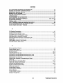
TABLE OF CONTENTS
Section .........................................................................Page
GENERAL ........................................................................... 5
BCD 4.4KW GENERAL SPECiFiCATIONS ...................... 10
BCD 4.4KW SYSTEM SPECIFICATIONS ........................ 11
BCD 6.0KW GENERAL SPECiFiCATIONS ...................... 14
BCD 6.0KW SYSTEM SPECIFICATIONS ........................ 15
INSTALLATION CHECKS ................................................. 18
DESCRIPTION OF
INSTRUMENT PANEL ...................................................... 29
PREPARATIONS FOR STARTING ................................... 32
STARTING PROCEDURE ................................................. 33
STOPPING PROCEDURE ................................................ 34
FUEL SYSTEM ................................................................. 36
DC ELECTRICAL SYSTEM .............................................. 39
BCD 4.4KW DC CONTROL CIRCUIT
WIRING DIAGRAM # 35951 ....................................42 & 43
BCD 6.0KW DC CONTROL CIRCUIT
WIRING DIAGRAM # 35773 ....................................44 & 45
COOLING SySTEM .......................................................... 46
LUBRICATION SYSTEM .................................................. 51
BC GENERATOR .............................................................. 54
GENERAL INFORMATION AND CARE
OF THE GENERATOR ..................................................... 61
ENGINE TROUBLESHOOTING ....................................... 63
MAINTENANCE & ADJUSTMENTS ................................. 66
3
Westerbeke Generators
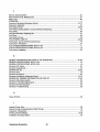
TABLE OF CONTENTS
(CONTINUED)
LAY-UP & RECOMMISSIONING ......................................75
TABLE OF STANDARD HARDWARE
TIGHTENING TORQUES ..................................................79
TABLE OF TIGHTENING TORQUES ...............................80
SPARE PARTS ..................................................................81
INDEX ................................................................................82
Westerbeke Generators
4
GENERAL
Introduction
This manual contains the equipment operating procedures as well as additional information needed to help
the operator keep the marine equipment in proper working order. Study and follow the instructions carefully. A planned maintenance program is included in this manual; adhering to the program will result in better
equipment performance and longer equipment life. Proper diagnosis of a problem is the most important step
to satisfactory repair; therefore, a troubleshooting table is included.
Understanding the Diesel Engine-Driven Generator
The diesel engine closely resembles the gasoline engine, since the mechanism is essentially the same. The
cylinders are arranged above a closed crankcase; the crankshaft is of the same general type as that of a
gasoline engine; and the diesel engine has the same type of valves, camshaft, pistons, connecting rods, and
lubricating system.
Therefore, to a great extent, a diesel engine requires the same preventive maintenance as a gasoline engine.
The most important factors are proper ventilation and proper maintenance of the fuel, lubricating and cooling systems. Replacement of fuel and lubricating filter elements at the time periods specified is a must, and
frequent checking for contamination (that is, water, sediment, or algae) in the fuel system is also essential.
Another important factor is the use of the same brand of high detergent diesel lubricating oil designed specifically for diesel engines. Be careful not to put gasoline in the diesel fuel tank(s). Gasoline does not have the
same lubricating qualities as diesel fuel; consequently, gasoline in the fuel lines will damage components in
the fuel lift pump assembly, fuel injection pump and injectors.
The diesel engine does differ from the gasoline engine, however, in its handling and firing of fuel. The carburetor and ignition systems are done away with and in their place are two components - the fuel injection
pump and the fuel injectors.
Ordering Parts
Whenever replacement parts are needed, always provide the generator model number, engine serial number, and generator serial number as they appear on the scarlet and gold name plate located on the generator end. You must provide us with this information so we may properly identify your generator set. In
addition, include a complete part description and part number for each part needed (see the separately furnished Parts List). Also, be sure to insist upon Westerbeke factory packaged parts because "will fit" or generiC
parts are frequently not made to the same specifications as original equipment.
Note that component locations in the manual are referenced from the front of the engine which is the pulley/drive belt end. (The flywheel/generator end is the rear end.) Left and right sides are determined by the
engine; imagine straddling the engine and facing in the same direction as the front of the engine: the left side
is at your left, the right side at your right.
Westerbeke generators sets are thoroughly checked and given a final run under various load conditions
before leaving the factory. Test running the generator ensures dependable operation, long service, and a
satisfied owner.
Care at the factory during assembly and thorough testing have resulted in a Westerbeke diesel engine-driven
generator capable of many thousands of hours of dependable service. However, what the manufacturer cannot control is the treatment the unit receives in the field. That part is up to the owner/operator.
5
Westerbeke Generators
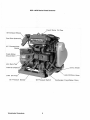
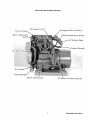
BCD 4.4KW Marine Diesel Generator
Fresh Water Fill Cap
45 0 Exhaust Elbow
i
Fuel Run Solenoid
AC
.Fr~shJII(~ter
Block Drain
Zinc Anode
Lube Oil Drain Hose
Lube
Oil Pressure Sender
Westerbeke Generators
Oil Pressure Switch
6
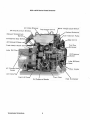
Exchanger Fresh Water Drain.
i
BCD 4.4KW Marine Diesel Generator
Emergency Shut-off Switch
: Fuel Lift Pump
E"~h~ust Temperature
SWitch f
45° Exhaust Elbow:
7
Westerbeke Generators
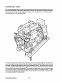
BCD 6.0KW Marine Diesel Generator
,20 Amp
DC Circuit Breake
Exhaust Temperature"
'SwItch
Emergency Stop Switc
45° Exhaust Elbow
AC
Westerbeke Generators
8
BCD 6~OKW Marine Diesel Generator
Fresh Water ~AirBleea
FreshWater
·c i rcufaiIn9~f:i~iiii?"'
Sea Water
~eat
Exc::hanger.
rter with Solenoid,
9
Westerbeke Generators
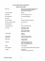
BCD 4.4KW MARINE DIESEL GENERATOR SET
GENERAL SPECIFICATIONS
Engine Type
Diesel, four-cycle, two-cylinder, fresh water-cooled
Vertical, in-line overhead valve mechanism
(8.6 hp at 1800 rpm, maximum).
Combustion Chamber
Swirl type
Bore & Stroke
2.68 x 3.07 inches (68 x 78 mm)
Piston Displacement
37 cubic inches (0.606 liters)
Firing Order
1-2
Direction of Rotation
Clockwise, when viewed from the front
Maximum Torque (at 1800 rpm)
33 Ib-ft (4.91 kg-m)
Compression Ratio
23:1
Compression Pressure
455 psi (32 kg/cm2) at 280 rpm
Valve Timing
Intake Opens 18° BTDC
Intake Closes 4SO ABDC
Exhaust Opens 46" BBDC
Exhaust Closes 1SO ATDC
Valve Seat Angle
Intake 45°
Exhaust 45°
Valve Clearance
(engine cold)
Intake 0.010 inches (0.25 mm)
Exhaust 0.010 inches (0.25 mm)
Engine Speed
1800 rpm 60 Hertz
1500 rpm 50 Hertz
Dimensions
Height: 23.25 inches (590.55 mm)
Width: 17.00 inches (431.18 mm)
Length: 27.25 inches (692.15 mm)
Weight
410 Ibs (186 kgs)
Fuel Consumption
0.5 U.S. gph (1.89lph) at full rated output (approximate)
Inclination
Continuous 15°
Temporary 20° (not to exceed 20 min.)
Westerbeke Generators
10
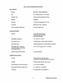
BCD 4.4KW SYSTEM SPECIFICATIONS
FUEL SYSTEM
General
Open flow - totally self-bleeding
Fuel
No.2 Diesel (cetane # 45 or better)
Injector Pump
In-line plunger type (Bosch M type)
Injectors
Pintle type
Lift Pump
12-Volt DC; lift capacity 6 ft (1.8 m)
Air cleaner
Metal screen type - cleanable
Air Flow (engine combustion)
19.2 cfm (0.544 cmm)
COOLING SYSTEM
General
Fresh water-cooled block,
thermostatically-controlled
with heat exchanger.
Operating Temperature
170 -1900 F (77 - 880 C)
Fresh Water Pump
Centrifugal type, metal impeller, belt-driven
Sea Water Pump
Positive displacement, rubber impeller, belt-driven.
Sea Water Flow, at 1800 rpm
(measured before discharging
into exhaust elbow)
3.50 - 3.75 U.S. gpm (13.24 - 14.19 Ipm)
System Capacity (fresh water)
6.0 qts (5.68 liters)
LUBRICATION SYSTEM
General
Pressure type by Trochoid pump,
gear-driven, with external pressure relief valve
Oil Filter
Full flow, paper element, spin-on type
Sump Capacity (not including filter)
2.5 U.S. qts (2.36 liters)
Operating Oil Pressure (engine hot)
35 - 55 psi (2.5 - 3.8 kglcm2)
Oil Grade
API specification of CF OR CG-4
11
Westerbeke Generators
BCD 4.4KW SYSTEM SPECIFICATIONS
ELECTRICAL SYSTEM
Starting Battery
12-Volt, 30 A-H, (-) negative ground
(recommended) (45 A-H in cold areas)
Battery Capacity
90 - 125 (Ampere-Hours)
Starter
12-Volt, 1.2 'r<YV, reduction type,
solenoid-mounted
DC No-Load Current
90 Amp (max.) at 11.5 Volts.
DC Cranking Current (engine cold)
175 - 200 Amps (engine cold)
DC Charging
Integral controller 0 - 10 Amps
13 -14 Volts DC
AC GENERATOR
General
Brushless, four-pole, revolving field.
Self exciting, capacitor saturated field excitation.
Pre-lubricated, single-bearing design.
Reconnectable 120 Volts or 120/240 Volts,
single-phase
Voltage
120 or 120/240 Volts - 60 Hertz
220 Volts - 50 Hertz.
Voltage regulation: ±5% no load to
full load.
Frequency regulation: ± 3 Hertz (5%)
no-load to full-load.
Rating (Volts AC)
60 Hertz (1800 rpm)
120 Volts
120/240 Volts
36 Amps
36/18 Amps
50 Hertz (1500 rpm)
220 Volts
15 Amps
AC Circuit Breaker
To be rated at 120% of the generator's rated
amperage and voltage output.
Generator Cooling
Air Requirements, (60 Hertz),
at 1800 rpm
Westerbeke Generators
175 - 200 cfm (4.95 - 5.66 cmm)
12
BCD 4.4KW SYSTEM SPECIFICATIONS
NQIE.: Increase air supply 15% for 50 Hertz operation (1500 rpm).
Engine Combustion Air
Requirements, (60 Hertz),
at 1800 rpm
19.2 cfm (0.544 cmm)
TUNE-UP SPECIFICATIONS
Injector Pressure
2275 psi +142 psi -0 psi
.
(120 kg/cm2 + 10kg/cm2 - Okg/cm2)
Engine Timing
190 BTDC at 1800 rpm
13
Westerbeke Generators
BCD 6.0KW MARINE DIESEL GENERATOR SET
GENERAL SPECIFICATIONS
Engine Type
Diesel, four-cycle, three-cylinder, fresh water-cooled
Vertical, in-line overhead valve mechanism
(12 hp at 1800 rpm, maximum).
Combustion Chamber
Swirl type
Bore & Stroke
2.56 x 3.07 inches (65 x 78 mm)
Piston Displacement
47.4 cubic inches (0.776 liters)
Firing Order
1-3-2
Direction of Rotation
Clockwise, when viewed from the front
Maximum Torque (at 1800 rpm)
42 Ib-ft (6.2 kg-m)
Compression Ratio
9.2:1
Compression Pressure
455 psi (32 kg/cm2) at 280 rpm
Valve Timing
Intake Opens 190 BTDC
Intake Closes 51 0 ABDC
Exhaust Opens 51 0 BBDC
Exhaust Closes 1go ATDC
Valve Seat Angle
Intake 45 0
Exhaust 450
Valve Clearance
(engine cold)
Intake 0.0071 inches (0.18 mm)
Exhaust 0.0017 inches (0.18 mm)
Engine Speed
1800 rpm 60 Hertz
1500 rpm 50 Hertz
Dimensions
Height: 23.38 inches (593.85 mm)
Width: 18.69 inches (474.73 mm)
Length: 26.75 inches (679.45 mm)
Weight
440 Ibs (199.6 kgs)
Fuel Consumption
0.7 U.S. gph (2.65lph) at full rated output (approximate)
Inclination
Continuous 150
Temporary 200 (not to exceed 20 min.)
Westerbeke Generators
14
BCD 6.0KW SYSTEM SPECIFICATIONS
FUEL SYSTEM
General
Open flow - totally self-bleeding
Fuel
No.2 Diesel (cetane # 45 or better)
Injector Pump
In-line plunger type (Bosch M type)
Injectors
Pintle type
Lift Pump
12-Volt DC; lift capacity 6 ft (1.8 m)
Air cleaner
Metal screen type - cleanable
Air Flow (engine combustion)
24.6 cfm (0.697 cmm)
COOLING SYSTEM
General
Fresh water-cooled block,
thermostatically-controlled
with heat exchanger.
Operating Temperature
170 - 190° F (77 - 88° C)
Fresh Water Pump
Centrifugal type, metal impeller, belt-driven
Sea Water Pump
Positive displacement, rubber impeller, belt-driven.
Sea Water Flow, at 1800 rpm
(measured before discharging
into exhaust elbow)
3.50 - 3.75 U.S. gpm (13.24 - 14.19 Ipm)
System Capacity (fresh water)
5.0 qts (4.73 liters)
LUBRICATION SYSTEM
General
Pressure type by Trochoid pump,
gear-driven, with external pressure relief valve
Oil Filter
Full flow, paper element, spin-on type
Sump Capacity (including filter)
3.3 U.S. qts (3.2 liters)
Operating Oil Pressure (engine hot)
35 - 55 psi (2.5 - 3.8 kg/cm2 )
Oil Grade
API specification of CF OR CG-4
15
Westerbeke Generators
BCD 6.0KW SYSTEM SPECIFICATIONS
ELECTRICAL SYSTEM
Starting Battery
12-Volt, 26 A-H, (-) negative ground
(recommended) (35 A-H in cold areas)
Battery Capacity
90 - 125 (Ampere-Hours)
Starter
12-Volt, 1.2KW, reduction type,
solenoid-mounted
DC No-Load Current
90 Amp (max.) at 11.5 Volts.
DC Cranking Current
(engine cold)
175 - 200 Amps (engine cold)
DC Charger
Integral controller 0 - 10 Amps
13 -14 Volts DC
AC GENERATOR
General
Brushless, four-pole, revolving field.
Self exciting, capacitor saturated field excitation.
Pre-lubricated, single-bearing design.
Reconnectable 120 Volts or 120/240 Volts,
single-phase
Voltage
120 or 120/240 Volts - 60 Hertz
220 Volts - 50 Hertz.
Voltage regulation: ±5% no load to
full load.
Frequency regulation: ± 3 Hertz (5%)
no-load to full-load.
Rating (Volts AC)
60 Hertz (1800 rpm)
120 Volts
120/240 Volts
50 Amps
50/25 Amps
50 Hertz (1500 rpm)
220 Volts
20.4 Amps
AC Circuit Breaker
To be rated at 120% ofthe generator's rated
amperage and voltage output.
Generator Cooling
Air Requirements, (60 Hertz),
at 1800 rpm
Westerbeke Generators
175 - 200 cfm (4.95 - 5.66 cmm)
16
MITE: Increase air supply 15% for 50 Hertz operation (1500 rpm).
Engine Combustion Air
Requirements, (60 Hertz),
at 1800 rpm
24.6 cfm (0.697 cmm)
TUNE-UP SPECIFICATIONS
Injector Pressure
2275 psi + 142 psi - 0 psi
(120 kg/cm2 + 1Okg/cm2 - Okg/cm2)
Engine Timing
19° BTDC at 1800 rpm
17
Westerbeke Generators
INSTALLATION CHECKS
General
Since the crafts in which Westerbeke generators are installed vary in design, installation procedures will vary
according to your craft's specific design. The intent of this section is not to advise boatyards or installers on
procedures already well-developed and well-understood. However, the owner/operator must realize there
are details of the installation which require periodic checks to ensure the best operating conditions for the
equipment and safe operating conditions for the personnel on board. Proper location and installation of the
diesel generator in the vessel are of prime importance.
Factors in the installation that must be considered are ventilation, to aid in cooling the generator end; to
provide air for engine combustion and to remove heat produced by the engine while operating; the exhaust
system, to properly discharge raw cooling water (sea water), to quiet the exhaust, and to expel exhaust gas;
the cooling water supply; and the electrical connections.
CAUTION
For safety reasons, the generator's engine is NOTfilied with lubricating oil for shipment. Before
leaving the factory, however, each generator set is thoroughly tested with oil in its engine.
This testing, among other things, provides all internal parts with a coating of oil. This oil acts
as a preservative, providing reliable protection against corrosion for at least one year if the
generator is properly stored.
Inspection of Equipment
The generator is shipped from the factory securely mounted and properly crated. Accessory equipment is
shipped in a separate small box, usually packed within the generator's crate.
Before accepting shipment of the generator set from the transportation company, the crate should be opened
and the contents inspected for concealed damage. If either visible or concealed damage is noted, you should
require the delivery agent sign "Received in damaged condition" on the proper delivery receipt. Also check
the contents of the shipment against the packing list and make sure that the proper notation is made if any
discrepancies exist. These noted discrepancies are your protection against loss or damage. Claims concerning loss or damage must be made to the carrier, not to the Westerbeke Corporation.
Westerbeke Generators
18
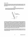
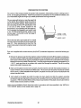
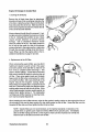
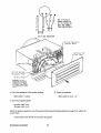
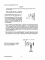
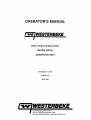
Rigging and Lifting
The generator is fitted with lifting eyes. Rope or chain slings capable of supporting the generator's weight
should be attached to the eyes and the generator lifted by means of tackle attached to these slings. The lifting eyes have been designed to carry the full weight of the generator; therefore, auxiliary slings are not required or desired.
CAUTION
Slings must not be so short as to place significant stress on the generator's lifting eyes. Strain
placed on the generator's lifting eyes by the lifting sling should be reduced as much as possible by using longer lifting slings when possible.
SLING LIFTING
ANGLE SHOULD BE
AS SMALL AS POSSIBLE
LIFTING
EYE
ENGINE
The general rule in moving generators is to see that all equipment used is amply strong and firmly fixed in
place. Move the engine a little at a time and see that it is firmly supported. Eliminate the possibility of accidents by avoiding haste. Do not lift the generator by its crankshaft pulley. In certain situations it may be
necessary to lift the engine in positions other than the horizontal position. Certain situations exist by which
the engine must be lowered endwise through a small hatchway which cannot be made larger. Under these
conditions, If the opening of the hatchway is extremely small, it is possible to reduce, to some extent, the
outside dimensions of the generator by removing external components such as the cooling system's piping,
the heat exchanger, certain filters, the mounting rails and other obstructive equipment. This accessory equipment should be removed by a competent mechanic and special care should be taken to avoid damage to
any exposed parts. In addition, be careful not to allow dirt from entering any opening created by the removal
of equipment. Removed parts should be returned to their respective position once the generator is in its in~
stallation area. Replace gaskets as needed for the parts that were removed.
In case it becomes necessary to hoist the generator front-end upwards or generator-end upwards, the attachment of lifting slings must be done carefully to avoid the possibility of damaging the parts on which the
weight of the slings may bear. Special rigging work is best done by someone experienced and competent
in handling heavy machinery.
19
Westerbeke Generators
Generator Mounting - Location
The complete generator unit is mounted on lightweight rails by means of four flexible isolator mounts that
help prevent the transfer of vibration from the generator to the rails. Each generator mounting rail has several
1/2-inch bolt holes so bolts can be employed to properly secure the generator to its mounting platform.
These holes are on 15 inch mounting centers.
The location should be dry, above low-lying vapor areas, and in an area where bilge water and water from
above cannot splash on the generator. It should be properly ventilated and accessible for minor servicing
and repairs. Access for major repairs should be given consideration as well. The location should be properly ventilated to provide fresh cooling air for the generator end, for engine combustion needs, and to remove
heat produced by the engine while operating. The generator set needs fresh cool air in whatever location
in the vessel it is installed. Hot generator discharge air must be removed from the generator area. The platform on which the generator and its mounting rails are located should be strong enough to support the generator during all angles of vessel operation.
Westerbeke Generators
20
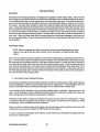
Exhaust System
IWARNINGI
Although diesel fuel is not as dangerous as gasoline, precautions should be taken to guard
against CARBON MONOXIDE GAS. Carbon monoxide is a dangerous gas that can cause unconsciousness and is potentially lethal. Some of the symptoms or signs of carbon monoxide
inhalation or poisoning are listed below.
o Dizziness
o Intense Headache
o Weakness and Sleepiness
o Vomiting
o Muscular Twitching
o Throbbing in Temples
All exhaust systems should be such that the entry of sea water into the engine's exhaust manifold and
cylinders is prevented while the engine is not running, or while the vessel is under sail or power in which case
the vessel may experience heeling or backing down from following seas or any other conditions. Special attention must be taken to make certain the exhaust system is secure, tight and free of leaks. The sea water
supply through-hull sea cock fittings must be of the flush-hull type. High-speed scoop type fittings must not
be used, as they tend to encourage siphoning.
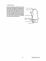
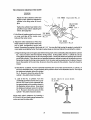
When a water lift type exhaust system is used, the exhaust muffler should be mounted as close to the engine
as practical. The exhaust discharge
should always drop downward into the
exhaust muffler. Loops in the exhaust
hose between the water-injected exhaust elbow and the water lift muffler
should be avoided, as these will trap and
hold water.
For installations where the exhaust
manifold/Water-injected exhaust elbow
is at or below the vessel's water line,
provisions must be made to install a
siphon-break or a vent in the sea water
supply hose to the water-injected exhaust elbow. This stops the flow of sea
water that runs through the sea water
cooling system from filling the exhaust
and engine cylinders when the engine is
shut down. This sea water supply hose
must be looped above the water line and
the siphon-break or vent installed in the
high point of the loop above the water
line. This siphon-break or vent must always be above the water line during all
angles of vessel operation to prevent
siphoning. The vent, when used, must
have its vent hose or tube routed so it
can remain above the water line and
empty of water when the engine is shut
down. This allows air to enter through
this vent to prevent siphoning.
SEI
VRTER
PUNP
GElUIIOI Rlon WITEI LIIE
!EIUITOR BElOW WilER LIIE
21
Westerbeke Generators
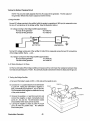
Exhaust Back-Pressure
The exhaust discharge hose must be of adequate size and
minimal run to prevent excessive exhaust back-pressure.
Exhaust back-pressure should be checked before a generator is put into service. (Refer to the illustration.) Excessive
back-pressure will affect the engine's performance and the
generator's power output.
To measure for back-pressure, use a mercury manometer, a
pressure gauge, or a water column. A boatyard or marine
mechanic should have a manometer or a pressure gauge.
Measure the engine's back-pressure at the exhaust elbow
while the generator is under a full load.
Exhaust
Elbow
Exhaust
Refer to the pressure specifications listed below.
A water column can be made by taking a clear plastic tube
and taping one end of the tube along a yardstick and fitting
the other end of the tube with a 1/4 inch NPT (National Pipe
Tap) pipe fitting.
Measure the engine's back-pressure at the exhaust elbow
while the generator is under a full load.
Dimension A cannot exceed 39 inches of water.
Back pressure, as measured by a gauge instrument, should
not exceed the following specifications:
Specifications:
2 inches of mercury
27 inches of water in a water column
15.6 ounces PSI
1.0 PSI
Excessive back-pressure can be caused by a small diameter exhaust hose, a small muffler, sharp bends in
the exhaust hose, improper fittings, water pockets, and a high volume of water in the exhaust system due
to the length of the exhaust discharge hose. The use of elbows and fittings in the exhaust discharge hose's
routing should be limited since these will create flow restrictions and contribute to exhaust back-pressure.
The generator's exhaust system must be separate from any other engine's exhaust system. Dry portions of
the exhaust system between the engine's exhaust manifold and the water injected exhaust elbow must be
insulated to hold in the heat.
Westerbeke Generators
22
P"L"PP~R
Dry stack-type exhaust systems
(shown to the right) must be attached to the generator engine's exhaust manifold by means of a flexible
connector pipe. This system must be
properly supported and insulated to
prevent water from entering into the
engine's cylinders. Provisions must
be made for discharging the
engine's cooling sea water.
CDVE"
~
iI
DRY STACK EXHAUST
Exhaust System Failures
When the engine's sea water is fed into an exhaust system so that the full stream of this water strikes a surface, erosion takes place. This erosion may cause premature failures. The proper design of either a water
jacketed or water injected ''Wet'' exhaust system to prevent this problem requires that the sea water inlet be
positioned so that the entering stream of sea water does not directly strike a surface. In addition, the velocity
of the entering sea water stream should be as low as possible, which can be achieved by having inlet fittings
as big in diameter as possible.
The best protection against carbon monoxide poisoning is a daily inspection of the complete exhaust system. Check for leaks around manifolds, gaskets, and welds. Make sure exhaust lines are not heating surrounding areas excessively. If excessive heat is present, correct the situation immediately. If you notice a
change in the sound or appearance of the exhaust system, shut down the unit immediately and have the system inspected and repaired at once by a qualified mechanic.
Make sure there are no unnecessary objects suspended from any portion of the exhaust lines. Excessive
weight could cause deflection or distortion of the lines, resulting in damage or leaks. Inspect insulated portions of the exhaust system to make sure there is no deterioration of the insulation.
NOTE: A maximum of 8 Ibs can be attached to the exhaust manifold without support.
CAUTION
Prolonged cranking intervals without the engine starting can result in filling the engine-mounted
exhaust system with sea water coolant. This may happen because the sea water pump is
pumping sea water through the sea water cooling system during cranking. This sea water can
enter the engine's cylinders by way of the exhaust manifold once the exhaust system fills.
Prevent this from happening by closing the sea water supply through-hull shut-off, drain the
exhaust muffler, and correct the cause for the excessive engine cranking needed to obtain a
start. Engine damage resulting from this type of sea water entry is not a warrantable issue; the
owner/operator should keep this in mind.
23
Westerbeke Generators
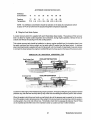
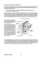
Exhaust Elbow Installation
The Westerbeke Corporation offers a 45°and 900 exhaust
elbow as well as an exhaust riser you can install on your
propulsion engine. Refer to the instructions below when
installing the exhaust elbow purchased for your generator.
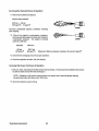
1. Coat only one side of the exhaust gasket with *"High
Tack" adhesive sealant. Place this coated surface
against the exhaust manifold's exhaust port flange (the
gasket should stick to the flange without falling off).
2. Place the clamp over the elbow's flange. Place your exhaust elbow against the exhaust manifold's flange so
the exhaust manifold's flange rests snug against the exhaust elbow's flange with the gasket centered between
the two. Now slip the exhaust clamp over both flanges.
45° ELBOW
3. A. Tighten the clamp just enough so the exhaust elbow
can remain attached to the manifold and still be
rotated.
B. The exhaust elbow discharge must be directed
downward so the mixture of sea water and exhaust
gases will flowlfall downward into the exhaust muffler which must be positioned below the exhaust
elbow. There should be no loops or rises in the exhaust hose connected between the exhaust elbow
and the muffler, as these would trap water and possibly allow water to flow back into the engine during
starting or at shut down.
90° ELBOW
4. Adjust the elbow by rotating it until the desired alignment with the exhaust piping is acquired.
5. Carefully tighten the clamp between 2 to 3Ib-ft, or 24
to 35Ib-in, or 0.27 to 0.41 kg-m.
CAUTION
Approach the 3 Ib-ft torque limit with caution. The
clamp's threads will break if more than 3 Ib-ft is applied to the clamp.
If a leak exists, correct it immediately.
* Manufactured by Permatex Company, Brooklyn, N.Y.
EXHAUST RISER
CLRMP
Westerbeke Generators
24
Fuel System
The fuel system should be installed in such a manner as to allow the engine-mounted fuel lift pump to pump
to maintain a positive inlet pressure to the injection pump under all operating conditions. The minimum size
of the fuel supply line and fuel return line is 1/4 inch, inside diameter, and there should be a primary fuel filter installed between the fuel tank and the fuel lift pump. Only one fuel filter is installed on the engine, between the mechanical fuel lift pump and the injection pump; this filter has a replaceable filter element.
The fuel tank's fuel pickup tube should be clear and unobstructed. No screens or gauze strainers should be
incorporated in the fuel pickup tube.
Make sure that the fuel supply and return lines are securely anchored to prevent chafing and that all fittings
are sufficiently tightened to prevent leaking. Also make sure your fuel system has a positive shut-off valve;
know its location and how it operates.
NOTE: DO NOT use spring-loaded check valves in the fuel supply line in lieu of mechanical
shut-off valves. This type valve can create fuel starvation problems for the engine's fuel system.
Fuel tanks that are located below the engine's fuel system level must have its fuel return at the tank extending down into the tank in the same manner as the pickup tube, otherwise fuel siphoning out of the engine's
fuel system through the return will take place.
Make sure the fuel tank filler is properly sealed to prevent water entry should it become awash. The fuel
tank's vent should be routed so as to prevent water entry as well.
Be sure there is a fire extinguisher installed near the unit and that it is properly maintained. Be familiar with
its use. An extinguisher with the NFPA rating of ABC is appropriate for all applications in this environment.
Oil Drain Hose
An oil sump drain hose is installed on the engine with the discharge end secured by a bracket at the front of
the engine. Oil may be drained from this hose by removing the cap and the discharge end of the hose from
the support bracket and lowering the hose into a container. The hose cap fitting is 1/4 inch NPT (National
Pipe Tap) and can be extended, or have a pump added, for easier removal of the old oil, if desired.
Connecting Pressure Sensing Devices to Oil Galleries
Oil pressure sensing devices, such as senders and switches, must not be connected to an engine's oil gallery with the use of extended nipples or tees. The reason is simply that continued engine vibration causes
fatigue of the fittings used to make such a connection. If these fittings fail during engine operation, lubricating oil will be lost and internal engine damage will result.
When additional sensing devices such as switches or sensors need to be installed that function on engine
oil pressure, these devices must be bulkhead-mounted and connected to the oil gallery using an appropriate
grade of lubricating oil hose. Any fittings used to connect the hose to the gallery must be of steel or malleable iron composition. Brass must not be used for this application.
25
Westerbeke Generators
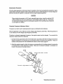
Sea Water Intake System
Make sure the intake system (sea water cooling system) is in proper order. Check that the hull inlet, sea
cock and strainer are unobstructed. Sea cocks and strainers should be at least one size greater than the
inlet thread of the sea water pump. The strainer should be of the type that may be withdrawn for cleaning
while the vessel is at sea and should be mounted below the water line to ensure self-priming. Inspect the
sea water lines to make sure there are no collapsed sections, which would restrict water flow. Make sure
there are no air leaks at any of the connections.
Cooling System
The generator's engine is fresh water-cooled by an
engine-mounted heat exchanger. Sea water is used
as the heat exchange's cooling medium. Sea water
is pumped into the exchanger by a sea water pump
and is then injected into the exhaust discharge, carrying with it the heat removed from the engine's fresh
water cooling system.
Sea water should be supplied to the sea water pump
through a flush-type through-hull fitting using a wirereinforced hose between the through-hull fitting and
the sea water pump. This sea water should be
directed through a visual-type sea water strainer and
then delivered to the pump. Hoses routed from the
through-hull fitting to the strainer and to the sea water
pump should be wire-reinforced to prevent the hose
from collapsing during the generator's operation (suction from the pump may collapse a non-reinforced
hose). Sea water strainers should be mounted at or
below the water line to make sure the sea water line
remains primed.
DEflECTION AT
LONGEST SPAN
CAUTION
DO NOT use a scoop-type through-hull fitting as a means of supplying sea water to the generator. Water pressure against this type fitting, while the vessel is under way, can push sea
water past the sea water pump's impeller into the generator's exhaust system, filling it and the
engine as well. Flush-type, clear, through-hull fittings are recommended and should be located on the hull so as to be below the waterline during all angles of boat operation.
The use of common-type street elbows is not recommended for plumbing the sea water circuit. These
generally have very restrictive inside diameters. Machined fittings are preferred.
Electrical System
The electrical system should be checked to make sure all wiring harnesses are properly tied down with
clamps or plastic ties and that all wiring harnesses are spaced at intervals close enough to prevent chafing
from vibration. Check to make sure all engine harness connections are tight and that they are made to the
appropriate terminals.
Westerbeke Generators
26
DC Electrical Connections
A common ground for the negative (-) DC terminal connection is found at the bell housing of the generator,
next to the starter, in the form of a threaded grounding stud. The battery ground should be connected at
this stud.
Connect the battery's positive ( +) connection to the starter solenoid tagged for this connection.
CAUTION
To avoid an overcharging condition, and a possible equipment failure, DO NOT disconnect
the DC battery source while the engine is running.
Automatic Shutdown
High Exhaust Temperature Shutdown Switch (normally closed)
An exhaust temperature switch is located on the exhaust elbow. Should the switch's sensor indicate an excessive exhaust temperature, the switch will open and shut the generator OFF (an inadequate supply of sea
water coolant causes high exhaust temperatures). This switch opens at 260 - 2700 F (127 - 1320 C) and
resets at approximately 2250 F (1 O~ C).
High Water Temperature Shutdown Switch (normally closed)
A high water temperature switch is located on the thermostat housing. Should the fresh water coolant's
operating temperature reach approximately 2050 F (960 C), the switch will open and shut the generator OFF.
This switch resets at 1950 F (10~ C).
Low Oil Pressure Shutdown Switch (normally open)
A low oil pressure shutdown switch is located off the engine's oil gallery. The switch's sensor monitors the
engine's oil pressure. Should the engine's oil pressure fall to 10 - 15 psi, the switch will open and turn the
generator OFF.
Generator (AC Output)
Make sure that the AC output connections within the generator's distribution box are tight and in accordance
with the specific AC Load Connections diagram found later in this manual. (See the "BC GENERATOR" section of this manual, page 54.)
Do not smoke or allow an open flame near batteries. Lead acid batteries emit hydrogen, a
highly-explosive gas.
27
Westerbeke Generators
Batteries
Make sure the positive ( + ) battery connection is connected to the battery connection of the starting solenoid.
The negative (-) battery connection should be connected to the system ground (the engine block).
When servicing the battery or checking the electrolyte level, wear rubber gloves, a rubber
apron, and eye protection. Battery acid may splash on the skin or into the eyes inadvertently when removing the electrolyte caps.
Check the battery's electrolyte level and specific gravity to ensure maximum engine starting efficiency. Make
sure the battery's terminals are clean and tight.
Ventilation
The ventilation requirements of the generator sets include the following: combustion air is required for the
engine cylinders; cooling air is required for the generator end and also for removing the heat produced by
the generator's engine during operation; and ventilating air is required to clear the bilges below the generator, as well as the compartment in which the generator is located, of potentially toxic and flammable diesel
vapors.
Keep in mind that hot air rises, so heated air should be removed from the upper area of the generator compartment and cool fresh air should be directed to the lower areas of the compartment. Ventilation should
be accomplished with the aid of blowers especially when the vessel is not underway. Refer to the "SYSTEM
SPECIFICATIONS" section of this manual for the airflow requirements of the generator sets, page 11 for the
BCD 4.4KW, and page 15 for the BCD 6.0KW.
Westerbeke Generators
28
DESCRIPTION OF INSTRUMENT PANEL
o
o
PREHEAT
~
....
1
."'
.~'.
,\
@
STOP
\..... _.....
..: .
o
o
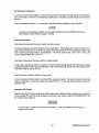
General
The manually-operated series of Westerbeke generators is equipped with toggle switches and, optionally,
remote panels. The Standard Instrument Panel (shown above) includes two gauges which indicate water
temperature in degrees Fahrenheit (WATER oF) and oil pressure in pounds per square inch (OIL PSI). This
panel is also equipped with two meters which indicate DC control circuit voltage (VOLTS) and the generator's running time (ELAPSED TIME) in HOURS and in 1/10 hours. The water temperature and oil pressure
gauges and the DC volt meter are illuminated; the ELAPSED TIME meter is not illuminated.
1. PREHEAT: The PREHEAT switch energizes the engine's glow plugs, activates the electric fuel pump,
bypasses the engine's oil pressure switch, and activates the fuel run solenoid. In addition, this switch
energizes the START switch.
2. START: The START switch, when pressed, energizes the starter's solenoid which cranks the engine.
This switch will not operate electrically unless the PREHEAT switch is pressed and held at the same
time.
3.
SIOE.:. Through the STOP switch power is provided to the fuel solenoid. Opening this switch deactivates the fuel solenoid and shuts OFF fuel to the engine, thereby stopping the engine.
NOTE: When the engine is manually shut down, the water temperature gauge and oil pressure
gauge will continue to register the last temperature reading and oil pressure reading indicated
by the gauge before electrical power was turned OFF. The temperature gauge and oil pressure gauge will return to zero once electrical power is restored to these gauges.
29
Westerbeke Generators
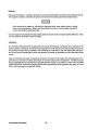
Remote Operation
For starting and stopping the generator at a remote location, the same three switches are used. The
PREHEAT and START switches are connected in parallel with the local panel's switches and serve the same
functions as in the local panel. The STOP switch is connected in series with the local panel's STOP switch
and serves the same function as in the local panel. The generator may be stopped from local or remote
positions
Refer to the remote panel wiring diagram when installing a remote instrument panel.
PANEL CONNECTIONS
BCD
BCD
REMOTE CONTROL PANEL (REAR VIEW)
r----------------
4.4KW
6.DKW
TO
STOP
RED
sw.
I
I
STOP
~-#-~4-C-R-N_+_(=____.J=:::J_ ~R~!!..
_
TO
PANEL GND
TO
PREHEAT
sw.
I
1118
r
BLK
I
I
I
I
I
;R~~E~Trl ______ ...!:.u....!!p...!:':....
SWITCH
RED
-------------
#~4RED
#~4RED
i
SW.
TO
PREHEAT
sw.
I
L--~-------------l------~~~P. N. 24943
Westerbeke Generators
TO
PREHEAT
30
TO
START
SW.
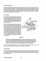
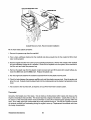
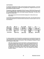
Description of Starting System
Westerbeke diesel engines use electric starters assisted by glow plugs for both normal and cold weather
starting. The figure below shows a cross-sectional view of one cylinder. The glow plug is located in the combustion chamber so that its tip is in the injector nozzle's spray path. When the glow plug is energized by the
PREHEAT button, the plug glows red at the tip and assists in igniting the fuel. The result is a rapid start with
less wear on the starter.
This system is common to Westerbeke Diesels. The start circuitry is designed so that the PREHEAT button
must be depressed for the time specified in the "Preheat" chart shown on page 33. Then, while keeping the
PREHEAT button engaged, the START button is depressed to crank the engine.
Combustion Chamber
NOTE: The START switch will not energize unless the PREHEAT button is depressed. When
depressing the preheat switch, we are activating the glow plugs in the cylinder head, so use
the preheat intermittently so as not to overheat the glow plugs.
31
Westerbeke Generators
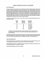
PREPARATION FOR STARTING
This section of the manual provides the operator with preparation, initial starting, break-in, starting (cold or
warm), and stopping procedures. Follow the procedures as presented, for the conditions indicated, and
your Westerbeke engine set will give you reliable performance and long service life.
Fill your engine with oil up to or near the upper limit
on the dipstick (the installation angle may have an
effect on the dipstick reading). Select readily available lubricating oil with an API specification of CC
or CD and an SAE number suitable for the
temperature in your operating area (see page 51).
For the quantity of oil needed in your engine, refer
to the "SYSTEM SPECIFICATION" section of this
manual, page 11 for the BCD 4.4KW, and page 15
for the BCD 6.0KW.
UPPER LIMIT
(NORMAL
LEUEL)
LOWER LIMIT
Fill the fuel tank with a good grade of No.2 diesel
fuel and prime the fuel system up to the engine (see
page 37). When returning fuel is free of air, the
engine's fuel system is bled and the engine is ready
to start.
Each unit is supplied with a coolant recovery kit (#24977) as standard equipment, to which the following applies:
A. Remove the pressure cap from the engine's exhaust manifold and slowly fill the engine's COOling system with a mixture of water and antifreeze suitable for your temperature zone. (See the "COOLING SYSTEM" section of this manual, page 46.) Operate the engine and observe the coolant level in the manifold.
Maintain this level to the base of the filler neck. Once the engine reaches its operating temperature (170
- 1900 F), make sure there is no problem with coolant flow through the manifold. Top off the COOling
system and install the pressure cap.
B. Make sure the plastic recovery tank is properly mounted near the unit (with the bracket provided), in a
location where it can be monitored and filled easily. The recovery tank should be mounted at manifold
level or above. In these installations that require it, the plastic recovery tank can be mounted below the
exhaust manifold's level.
C. Add coolant to the plastic tank after the engine has been started and after the engine's operating
temperature has been reached to make sure all air is expelled from the manifold and the engine's cooling system. With the manifold filled and the pressure cap installed, fill the plastic recovery tank half full.
Monitor daily and add coolant as needed.
Make sure the Installation Checks have been made in accordance with those specified in the "INSTALLATION CHECKS" section of this manual (refer to page 18).
Westerbeke Generators
32
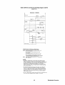
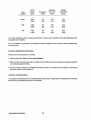
STARTING PROCEDURE
1. Depress and hold the PREHEAT switch. Preheat according to the following chart:
2. While still depressing the PREHEAT switch, depress the START switch. As soon as the engine runs, release
the START switch but continue to hold the PREHEAT switch depressed for an additional 2 to 3 seconds.
This allows the engine to build up enough oil pressure to close the oil pressure shutdown switch and allow
the engine to continue to run.
NOTE: Should the engine not start when the START switch is depressed for 10 to 12 seconds,
release both switches and wait 30 seconds; repeat the previous procedure. Never run the
starter motor for more than 30 seconds at a time.
3. Check all the instruments on the panel for proper operation. Make sure sea water discharges with the exhaust discharge.
Atmospheric Temperature
Preheating Time
+ 41° F (+ 5° C) or higher
+ 41° F (+ 5° C) to + 23° F (- 5° C)
Approx. 10 sec.
Approx. 20 sec.
Approx. 30 sec.
30 seconds
before cranking
+ 23° F (- 5° C) or lower
Limit of continuous use
Once the engine starts, allow it to run for a few minutes to warm up
and stabilize while the engine's instruments are checked for proper
oil pressure and battery charging Voltage. Never attempt to
engage the starter while the engine is running.
NOTE: Some unstable running may occur in a cold engine, but
this condition should smooth out as the operating temperature of
130 - 150° F (55 - 66" C) is reached.
Proper glow plug function is indicated by a voltmeter drop when
the PREHEAT switch is depressed. This drop will be slight but discernible. If no voltage drop is noted, it may indicate defective glow
plugs or a faulty preheat circuit (check for loose connections).
CAUTION
Prolonged cranking intervals without the engine starting can result in filling the engine-mounted
exhaust system with sea water coolant. This may happen because the sea water pump is
pumping sea water through the sea water cooling system during cranking. This sea water can
enter the engine's cylinder's by way of the exhaust manifold once the exhaust system fills.
Prevent this from happening by closing the sea water supply through-hull shut-off, drain the
exhaust muffler, and correct the cause for the excessive engine cranking needed to obtain a
start. Engine damage resulting from this type of sea water entry is not a warrantable issue;
the owner/operator should keep this in mind.
33
Westerbeke Generators
STOPPING PROCEDURES
1. Remove the AC electrical load from the generator and allow the generator to run for 3 to 5 minutes so the
engine can stabilize its operating temperatures.
2. Depress the STOP switch and hold it until the generator comes to a complete stop. Now release this
switch.
Engine Break-In Procedures
Although your engine has experienced a minimum of one hour of test operations to make sure accurate assembly procedures were followed and that the engine operated properly, a break-in time is required. The
service life of your engine is dependent upon how the engine is operated and serviced during its initial hours
of use.
Your new engine requires approximately 50 hours of initial conditioning operation to break in each moving
part in order to maximize the performance and service life of the engine. Perform this conditioning carefully, keeping in mind the following:
1. Start the engine according to the "STARTING PROCEDURE" section found on page 33; run the engine
while checking that all systems (sea water pump, oil pressure, battery charging) are functioning.
2. Start the generator and allow the engine to warm up until the water temperature gauge moves into the
130-140° F range.
3. Use caution not to overload the generator. The presence of a gray or black exhaust with loss of engine
rpm (Hertz) are signs of a possible overload.
4. Run the generator at 1/2 of its rated capacity for the first 10 hours then increase the load to 3/4 of its
rated capacity. For the remainder of the break-in period, the generator may be run at different load intervals.
Breaking-in a new engine basically involves seating the piston rings to the cylinder walls. Excessive oil consumption and smoky operation indicate that the cylinder walls are scored, which is caused by overloading
the generator during the break-in period
As indicated above, operate the generator with a moderate load during the 50-hour break-in period. (On
one hand don't baby the engine, but on the other hand, however, don't abuse it.)
Westerbeke Generators
34
Starting Under Normal Conditions
Follow the procedure below for normal starting of the generator:
1. Make sure there is sufficient fuel on board. Keep fuel tank(s) as full as possible. Check the fuel filters
and water separators for the presence of contaminants and/or water. Drain and clean them as needed.
3. Check the coolant level in the plastic recovery tank. Add coolant solution as needed.
NOTE: Excessive loss of coolant from the plastic recovery tank indicates a cooling system
leak. Check the entire cooling system and pressurize the system to locate the leak. In cases
of excessive coolant loss, the system must be refilled as outlined under the "PREPARATION
FOR STARTING" section of this manual, page 32.
4. Check the oil level in the engine sump and look for any and fuel leaks, particularly if signs of such leaks
are found on the bottom of the engine or below the engine.
Start the generator in accordance with the "STARTING PROCEDURE" instructions found on page 33, and
allow the engine's operating temperature to reach 140 - 1500 F before placing load on it.
Starting Under Cold Conditions
Under extremely cold temperatures, the following conditions can occur. Follow the instructions listed below
when operating your engine in cold weather.
LUBRICATING OIL TURNS VISCOUS - Make certain that the lubricating oil used conforms with the ratings
for the prevailing atmospheric temperature. Refer to the "LUBRICATION SYSTEM" section of this manual,
page 51 for an atmospheric/oil viscosity specification table.
VOLTAGE ACROSS THE BATTERY TERMINALS DROPS - Make certain that the battery is fully charged to
minimize voltage drop across the battery terminals.
THE TEMPERATURE OF THE INTAKE AIR IS LOW AND THE COMPRESSION TEMPERATURE DOES NOT
RISE ENOUGH - Allow the glow plugs to operate sufficiently to aid in starting during the preheat period whenever the temperature of the intake air is low and when the compression temperature does not rise enough.
Refer to the preheat chart found in the "STARTING PROCEDURE" section, page 33.
35
Westerbeke Generators
FUEL SYSTEM
Diesel Fuel
Use No. 2 diesel fuel with a cetane rating of 45 or higher. Never use kerosene or home heating oil since
these fuels do not have the same lubricating properties as No.2 diesel fuel.
In cold weather particularly, water vapor is produced by condensation when air is present in the fuel tank.
Keep fuel tank(s) full and completely free of dirt and water.
Fuel Filters
A primary fuel filter of the water
entrapment type must be installed between the fuel tank and the engine. A
primary fuel filter, shown here, is
available from your local Westerbeke
representative or your boatbuilder.
This filter, adapted for boatbuilder
use, comes complete with fittings for
either hose or metal tubing. Mount it
in an accessible place, inspect it often
and drain off water accumulation frequently.
XNSTALLATXON XNSTRUCTXONS
1. BOLT SEDIKENlIlATEI TRAP SECUREU TO
AN ACCESSIBLE STRUCTURE SO POSITIONED
THAT A RECEPTICLE TO CAICN DRAINAGE
CAM BE PLACED UNDER II.
2. IF FUEL IS TD BE PIPED IIiN COPPER,
OR BUND' TUBINS, USE MUTS AMD FERRULES
PROUIDEO. BE SURE TNE TUBIIS PROJECTS
1/4 INCH THROUSH THE FERRULE BEFORE
IISHTEMIIG THE HUT.
3. IF FUEL IS TO BE PIPED .IIH HOSE, USE
THE TWO BRASS BARBED FIITIII&S AID UASHERS
SUPPLIED. BE CERTAII INAT IRE NIISE SELECTED
HAS OIASONAL BRAID INSERTED ITO CLIIS 01 THE
BARBl, IHAT IT IS HEDPREHE LIIED, AID THAT
II IS ~~~ APPROUED.
4. IF lATER IS PRESENT IN TNE FUEL, IT ¥IlL
If a water trap type filter is not installed
COLLECT SLOWLY II THE BOITO" OF THE
SEDI"EMIER. WHEN THE RED FLOAT RINS
between the fuel tank and the engineREACNES THE DAAIN LIIE ON THE PLISTIC
mounted fuel system, any water in the
BOIL, LOOSEN THE 1UJ1l0" ORRII PLUS UIIIL
All lATER RUNS OUT.
fuel system will tend to lay in the bot5. TIGHTEM DRAIN PLUC SECURElY SO NO AIR CAN
tom of the electric lift pump. Internal
ENTER THE StSTEI.
metal parts of the lift pump will rust.
&. ENERGIZE THE FUEL PUMP TO REFILL THE
Particles will pass on to filters and
BOUL.
eventually to the injection pump and
injectors with damaging results and
the possibility of expensive repairs.
Remember, water damage to the fuel
system is not covered under the
Westerbeke warranty. The owner/operator is responsible in making sure that fuel reaching the engine's injection equipment is free of impurities. This process is accomplished by installing a proper filtration/separation system and maintaining this system.
In addition, any gasoline in the fuel system will damage the engine's fuel injection pump assembly and injectors, as gasoline does not have the same lubricating qualities as diesel fuel.
Although most boatbuilders supply a water trap/filter, some do not. Westerbeke offers a sedimentary/water
trap/filter as an optional extra at moderate cost. The filter is supplied with fittings for either hose or metal
tubing fuel lines.
Westerbeke Generator
36
Priming the Fuel System
The Westerbeke self-bleeding fuel system is semiautomatic in operation. The self-bleeding feature of the fuel
system allows for easy servicing of the fuel filters. Simply remove the and replace the filter elements (take
care in catching any fuel that may drain out of the fuel filtering assemblies) as described in the "Replacing
the Fuel Filter Elements" section below. Energize the PREHEAT switch and allow the electric fuel pump to
operate for 20 to 30 seconds to prime and bleed air from the system. (No fittings should be opened.) Then
proceed to start the engine as you normally would. If the engine does not start, stop and wait a few moments, and then repeat the bleed procedure as indicated above. When the PREHEAT switch is depressed,
the preheat elements (the glow plugs) are energized, so take care not to over heat them.
CAUTION
Prolonged cranking intervals without the engine starting can result in filling the engine-mounted
exhaust system with sea water coolant. This may happen because the sea water pump is
pumping sea water through the sea water cooling system during cranking. This sea water can
enter the engine's cylinders by way of the exhaust manifold once the exhaust system fills.
Prevent this from happening by closing the sea water supply through-hull shut-off, drain the
exhaust muffler, and correct the cause for the excessive engine cranking needed to obtain a
start. Engine damage resulting from this type of sea water entry is not a warrantable issue;
the owner/operator should keep this in mind.
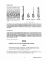
ReplaCing the Fuel Filter Elements
While it is unlikely that the operator will be forced to service the system at sea, the possibility does exist.
Therefore, it is recommended that banjo washers, injector seat washers, electric lift pump filter and gasket,
fuel filter and gasket be carried on board at all times. Select the parts for your engine from the Parts List and
purchase spares from your local Westerbeke Dealer or Distributor. For example, hardware kit #33093 includes replacement elements with gaskets (items #6,
8, 20, 21). If a leak should develop at a fuel banjo or
sealing washer location that cannot be remedied by a
slight tightening of the filter cup retainer, replace the filter along with the O-rings supplied with the new filter.
After the first 50 hours of operation, loosen retainer ring
# 23 and discard filter element # 21. Clean bowl # 22
and install a new filter using a new # 20 gasket. Be
careful to catch any fuel that may spill from within these
fuel filter assemblies. This same service is required of
the # 6 filter element in the electric fuel lift pump.
Similarly, install a new # 6 filter element along with a
new # 8 gasket. The base of the electric fuel pump is
removed with the aid of an open end wrench. Twist the
base off the pump's locking tabs and reinstall the base
by twisting it back on the locking tabs. Place the wrench
on the hex nut cast into the base.
After the first 50-hour change, the change period may
be increased to 200 hours or once per season.
37
~
I
8
23
Westerbeke Generator
Fuel Injection Pump
The illustration below shows the BCD 6.0KW's fuel system. The BCD 4.4KW fuel system's differs in that it
has one less fuel injector and injector pump plunger. The fuel injection pump, located to the right, is one of
the most important components of the diesel engine and, therefore, calls for the utmost caution in handling.
Furthermore, the fuel injection pump has been thoroughly bench-tested and should not be tampered with.
Speed (Hertz) and timing adjustment are the only adjustments the servicing dealer can perform on the injection pump. Other types of adjustments or repairs must be performed by a qualified injection service shop.
ELECTRIC FUEL
LI FT PUMP
Fuel Injection System
To obtain long and satisfactory service from the injection pump, always use fuel which is free from impurities
and maintain a good filtration and water separation system between the fuel tank and engine. Service this
system regularly: the injection pump it saves will be your own.
Westerbeke Generator
38
DC ELECTRICAL SYSTEM
Engine 12-Volt DC Control Circuit
The Westerbeke BCD 4.4KW and BCD 6.0KW generators have a 12-Volt DC electrical control circuit, as shown
on the wiring diagrams which follow on pages 42 and 45. Refer to these diagrams when troubleshooting or
servicing electrical components on the engine.
CAUTION
To avoid damage to the battery charging circuit, never shut off the engine battery switch while
the engine is running.
Shut off the engine battery switch, however, to avoid electrical shorts when working on the engine electrical circuit.
Battery Specification
The minimum recommended capacity of the battery used in the engine's 12-Volt DC control circuit is 90 125 Ampere-hours (minimum).
39
Westerbeke Generator
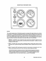
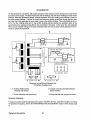
Testing the Battery Charging Circuit
NOTE: This circuit is totally separate from the AC output of the generator. The AC output of
the generator effects this circuit's output but not the reverse.
1. Bridge Rectifier
Normal AC voltage running to the rectifier (while the engine is operating at 1800 rpm) is measured across
the two AC connections on the bridge rectifier. (See the illustration below.)
AC voltage running to the bridge rectifier (approximate):
16.0 Volts AC
No-load off the generator
17.5 Volts AC
Full-load off the generator
DC
+
AC
AC
-t>I-
I.C.
BRIDGE
RECTIFIER
INTEGRAL
CONTROLLER
Normal DC voltage running out of the rectifier (in Volts DC) is measured across the two DC connections
of the bridge rectifier; that is, + and - .
DC voltage running from the bridge rectifier (approximate):
17.0 Volts DC
No-load off the generator
Full-load off the generator
18.5 Volts DC
2. AC Stator Winding: 0.14 Ohms
Lift the two AC leads off the bridge rectifier and measure with an ohmmeter the resistance between these
two leads should measure 0.14 Ohm. No continuity should exist between these two leads and the ground.
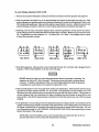
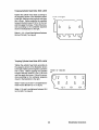
3. Testing the Bridge Rectifier
A. Set your Ohmmeter's scale on RX1 (+ DC) and set the needle to zero.
B. Connect the ( +) positive lead from the Ohmmeter
to point #4. Taking the Ohmmeter's negative (-)
lead, momentarily touch points #1, #2, #3, and #5.
The Ohmmeter should register no deflection for any
of the points touched.
- . - _ Point #3
C. Remove the positive (+) lead from point #4 and
connect the negative (-) lead; momentarily touch
points #1, #2, and #3. The Ohmmeter's needle
should deflect when each point is touched.
D. Leaving the negative (-) lead on point #4, touch
point #5 with the positive lead. No deflection
should take place.
Westerbeke Generator
40
E. Place the positive ( +) lead on point #1 and the negative (-) lead on point #3. The Ohmmeter again
should not register any deflection (no deflection indicated infinite resistance). Reverse these connections and the Ohmmeter should again register no deflection. IF THE RECTIFIER FAILS ANY OF THE
PREVIOUS TESTS (A - E), REPLACE THE RECTIFIER BECAUSE IT IS DEFECTIVE.
4. Integral Control/er (I.C.)
The integral controller (I.C.) is an encapsulated, solid-state unit that supplies a DC charging voltage to the
generator's starting battery while the generator is operating.
Charging Voltage:
13.0 -14.0 Volts DC
Charging Amperage:
0 - 10 Amps DC
A separate group of stator windings supplies AC voltage to a bridge rectifier which converts the AC current
into DC current to supply the I.C. unit. The I.C. unit senses the needs of the starting battery and supplies a
DC charge when one is needed. If you suspect that the I.C. unit is faulty (that is, if the battery's charge is
low), check the charging circuit's operating and components as described in steps 1-4. Check all connections for cleanliness and tightness including the ground before replacing the I.C. unit.
NOTE: When the generator is first started, the I.C. unit will produce a low charging rate. This charging
rate will rise as the generator is operated for awhile.
41
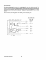
Westerbeke Generator
BCD 4.4KW DC Control Circuit Wiring Diagram #35951
page 1 of 2
~
DIAGRAM
WATER TEMP. •
SENC';R
~
¥
,,.~
~~Lp
n
T
.-o .~
~
~
OIL PRESSURE
SENDER
OIL PRESSU~E
~
EMERGENCY STOP SWITCH
CIRCUIT
BREAKER
Rt:.O"14
~
ALTERN~TOR
EXHAUST
TEMP. SWITCH
SEt
NOTE 2
~1
LtJ
I
I
I
~OUND
[1.....1
TO 8L..OCK
1
-l
PRE-HEAT
START
I
I
STOP
Westerbeke Generator
42
I
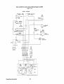
BCD 4.4KW DC Control Circuit Wiring Diagram #35951
page 2 of 2
SCHEMATIC
DIAGRAM
I
~ -: seE
.. ~ NOTE 2
START SOL.
STARTER
~--------~..., I----{M}--~
Q.OWPLUGS
, ,
:( : C.B.
~
p.H.SOL.
J 20A
G
EXM.r.sw,
O.P. sw.
W.T.SW.
"---J
~--+o-~
__-r'
__ ,
START
sw.
1____ ..:
p.t;,SW.
~
EMEF<.3'TOF- 5w.
__ .J
FUEL SOL.
W.T.
W.T.5NOR.
o.P. '---+-+-----\~----""""'
o.P.SNOR.
VOLTS;"---t-t-----1n'------t
I
I
I
HouRS
I
~--~~----------~
Ilfl/STRUMQI!"~ _ _ _ _ _ _ _
--.J
STARTING AND STOPPING INSTRUCTIONS
~: I. ALWAY: PU-:'H ~E-HEAT SWITCH FIRST. HOLD FOR 15 TO 60 SECONDS AS REQUIREO.
2.WHILE CONTINUING TO PUSH PRE-HEAT SWITCH 1 PUSH START SWITCH.
3. WHEN GENERr.TOw STARTS, RELEASE START SWITCH ONLY.
4.WHEN OIL PRE:SuRE REACHES AF-PROxIMATELY 20 PSI RELEASE FwE·HE/.T SWITCH
(THE J:.~E~EAT SWITCH OVEIO:IGES THE LOW OIL PRESSURE SHUT~OWN CIRCUIT).
~
PUSH ANO HOLD THE STOP SNITCH UNTil THE GENERATOR STOPS COMPLETELy.
I. TIoiIS PWQCUCT I:: PROTECTED BY A MANUAL RESET CIRCUIT BREI\KER LOCATED NEAR THE STARTER
AND AS CLOSE TO THE SouCE OF CUPRENT I\S ~OSSIBLE. EXCESSIVE CURRENT DRAW ANYWHERE
HJ THE INSTRuMENT PANEL OR ENGINE WIRING WILL CAUSE THE BREAKER TO TRIP. IN THIS EvENT
t~OST GENERATORS WILL SHUT DOW~I BEC/,USE
11-IE OPENED BREAKER DISCCNNECTS TI-IE FUEL SUPPLY.
THEREFORE THE BUILDER/OWNER f.4UST BE SU~E THAT THE INSTRUMENT PANEL A~O ENGINE WIRING
A~E
INSTALLED TO PREVENT CONTACT BETwEEN ELETRICAL DEvICES ANO ShLT WATER.
Z..AN O:-.l-OFF SWITCH SHOULD BE INSTALLED IN THIS CIRCUIT
TO
DISCO~NECT
THE STARTER FROM THE
BATTERY IN AN Ef-1E!(GENCY AND WHEN LEAVING THE BOAT. TWELVE VOLT DIESEL ENGINE STARTERS
TYPICALLY DRAW :'00 TO 500 AMPS WHEN CRANKING. THE
DURATION OF INDIVIDuAL CRANKING CYCLES
SHOWLD NOT EXCEED .30 SECONDS. A SWITCH WITH A CONTINUOUS F;'I\TING OF' [75 AMPS AT 12VDC WILL
'WILL NORMALLY SERVE.. THESE FUNCTIONS, SUT A SWITCH MUST NEvER 6f u~EO TO MAKE THE STARTER CIRCUIT•
.3.~OST STARTER
~~OLENOIDS DRAW
15 AMPS, THEREFOI1E THE VOLTAGE JRCP IN THIS CONDUCTOR MUST
EE NC GREATER THAN IOlelN THE PATH FF?OM THE STANOARO STAR: SWITCH
TO ANY RE~OTE SWITCHES
AND 8J\CI<': TO THE STANDARD
START SWITCH). IF TI-I15 qEOUIRES IMPRACTICALLY LARGE CONDUCTORS
T--tE~ A RELAY MAY BE ADDED
TO CONTROL THE STARTER SOLENOID ITSELF".
43
Westerbeke Generator
BCD 6.0KW DC Control Circuit Wiring Diagram #35773
page 1 of2
WIRING
~
,...-----'c---:;I;T llQe ~
DIAGRAM
~
EU!2
EXHAUST
TEMP, SWITCH
.-..
......
POWER
ALTERNATOR
r---'
I
0
I
I
I
I
I
I
fir,
'\-!
i
GND. '10 ILOCK
-
L~ SEE NOTE 2
l---a
BATTERY
STANDARD
"iNS'i'RuME NT
,
~
(REAR VIEW)
I
~---~
Westerbeke Generator
44
BCD 6.0KW DC Control Circuit Wiring Diagram #35773
page 2 of 2
SCHEMATIC
DIAGRAM
1
:,
,:SEENOnz
START SOL.
~--------------------------~"~---~-~'----~M ~5_T_AR_T_ffi__~
~-:j
L
PRE-MEAT SOl..
~------------~:~-i~-~;------~I--~GLOWPL~u7G5~----------~
; ):-~:~~~~R
"
"
POWER
J
AL'VERNATOR
~----~---------+----~~r-----~
BATTERY CHARGER
!,J(.11.T.SW.
W.T.SW.
5;. :~-("~ ~
""'-_ _ _
i
PRE-HEAT SW.
O.P.SW.
FU EL
PUMP
1"'-,--.
FUEl. 501..
EMERGENCY
STOP sw.
w.T.SENDER
Q..P.
SENDER
STARTING AND STOPPING INSTRUCTIONS
~: I. ALWAYS PUSH PRE-I-IEAT SWITCH FIRST. HOLD FOR 15 TO GO
SECONDS AS REOUIRED.
2. WHILE CONTINUING TO PUSH PRE-HEAT SWlrel-l PUSH
START SWITCH.
I
3. WHEN GENERATOR STARTS, ~ELEASE START SWITCH ONLY,
4. WHEN OIL PRESSURE ~EACHES APPROXI.~ATELY 20 PSI
RELEASE PRE-HEAT SWITCH (THE PRE'~EAT SWITCH OVERIOES
THE LOw OILPRES5URE SHuT DOWN CIRCUIT)
PUSH AND HOLD THE STOP SWITCH UNTIL
THE GENERATOR
STOPS COMPLETELY.
~:
I. THIS PRODUCT IS PROTECTED BY I\. MANUAL RESET CIRCUT BREAKER LOCATED
NEAR THE STi\RTER AND AS CLOSE TO THE SOURCE OF CURRE.NT AS P05SIBLE.
EXCESSIVE CUR.I1ENT OJ:;AW ANYWKERE IN THE INSTRUMENT PANEL WIRING OR ENGINE
...... ILL CAuSE THE BREAI(ER TO TRIP. IN THIS EVE!'\T MOST GENERATORS WILL SHUT
DOWN BEC.uSE THE
O~ENED
BREMER DISSCDNNECTS THE FUEL SUPPLY.
THE~E~ORE THE BUILDER/OWNER ~UST BE SURE THAT THE INSTRU,\4ENT PANEL
WIRING AND ENGINE ARE INSTALLED TO PFlEVENT CONTACT 8ET.¥e:EN ELECTRICAL
DEVICES AND SALT WATER.
O~ SWITCH SHOULD BE INSTALLEO IN THIS CIRCUIT TO DI5CDNNET THE
STARTER FROM THE BATTERY IN AN E~ERGENC.Y A"O WHEN LEAVING THE BOAT.
TWEl.VE vOLT DIESEL ENGINE STARTERS TYPICALLY DRAW 200 TO 300 AMPS WHEN
Z.AN ON
CRANKING. THE DURATION O~ INQIVIDUAL CRANKING CYCLES SHOUl.D NOT EXCEED
30 SECONDS. A SWITCH WITH A CQNrlNUQlJS RATING OF 175 AMPS AT IZVOC WILL
NORMALLY SERVE THESE FUNCTIONS BUT A SWITCH ,",USTNEVER BE USED TO
:o-1AKE THE 5TARTER CIRCUIT.
~. BATTERV
CHARGER CAUSES AI 9.-DRAIN WHEN GENERATOR IS NOT OP€RATING.WMEN
LEAVING BOAT FOR AN EXTENDED PERIOD DISCONNECT TME BATTERY.
45
Westerbeke Generator
COOLING SYSTEM
Description
Westerbeke marine diesel generators are designed and equipped for fresh water cooling. Heat produced
in the engine by combustion and friction is transferred to fresh water which circulates throughout the engine.
This circulating fresh water cools the engine block and its internal moving parts. The heat is transferred externally from the fresh water to sea water by means of a heat exchanger, similar in function to an automotive radiator. Sea water flows through the tubes of the heat exchanger while fresh water flows around the
tubes; engine heat transferred to the fresh water is conducted through the tube walls to the sea water which
is then pumped into the exhaust system where finally it is discharged overboard. In other words, the engine
is cooled by fresh water, the fresh water is cooled by sea water, and the sea water carries the transferred
heat over the side through the exhaust system. The fresh water and sea water circuits are independent of
each other. Using only fresh water within the engine allows the cooling water passages to stay clean and
free from harmful deposits. The two independent circuits and their components are discussed in the following paragraphs.
Fresh Water Circuit
NOTE: Refer to paragraphs A and B in this section for the recommended antifreeze and water
mixture to be used as the fresh water coolant, and for information on filling the fresh water
system.
Fresh water is pumped through the engine by a belt-driven circulating pump, absorbing heat from the engine. The fresh water coolant circulates through the engine's block absorbing heat, then passes through
the thermostat into the exhaust manifold, to the heat exchanger wher.e it is cooled, and then is returned to
the engine block through the suction side of the fresh water circulating pump. When the engine is started
cold, external fresh water flow is prevented by the closed thermostat (although some fresh water flow is
bypassed around the thermostat to prevent exhaust manifold from overheating). As the engine warms up,
the thermostat gradually opens, allowing full flow of the engine's fresh water coolant to flow unrestricted to
the external portion of the cooling system.
A. Fresh Water Coolant (Antifreeze) Mixture.
A freshwater and antifreeze mixture should be used year-round in the cooling system. Water, when it freezes,
expands sufficiently to split the heat exchanger and crack the engine block. A water/antifreeze mixture of
proper concentration will prevent freezing (see page 47 for an antifreeze/water mixture chart).
Use soft water with few impurities, such as tap water (potable water) or rainwater. Never use hard or foul
water. Use of hard water or water containing impurities will lead to the collection of scale in the engine and
heat exchanger which will reduce the cooling system's efficiency.
Antifreeze of poor quality or without rust inhibitors will cause corrosion within the cooling system. Always
use antifreeze which is compatible with aluminum cooling system components and is made by a reliable
manufacturer. Never mix different brands of antifreeze.
Make sure that the cooling system of the engine is well cleaned before adding antifreeze. Recommended
antifreeze for year round use is ZEREX or PRESTONE with rust inhibitors.
In order to control the concentration of the mixture, mix the antifreeze and freshwater thoroughly before adding it to the cooling system.
Westerbeke Generators
46
ANTIFREEZE CONCENTRATION DATA
Antifreeze
Concentration
%
Freezing
Temperature
eC)
°F
13
23
23
14
(-10)
(- 5)
30
35
45
50
60
5
-4
- 22 - 40 - 58
(-15) (- 20) (- 30) (- 40) (- 50)
NOTE: An antifreeze concentration should be selected on the basis of a temperature which
is about 10° F (5° C) lower than the actual atmospheric temperature expected.
B. Filling the Fresh Water System
A coolant recovery tank kit is supplied with each Westerbeke diesel engine. The purpose of this recovery
tank is to allow for engine coolant expansion and contraction, during engine operation, without the loss of
coolant and without introducing air into the cooling system.
This coolant recovery tank should be installed at, or above, engine manifold level, in a location where it can
be easily monitored and where coolant can be easily added if needed (see the figure below). A stainless
steel mounting bracket is supplied with each kit along with a 30-inch length of clear plastic hose and clamps
to connect the hose between the engine's manifold fitting to the hose spud on the base of the recovery tank.
FUNCTION OF MANIFOLD PRESSURE CAP
From Coolant Tank
to Coolant Tank
Coolant from the engine, when heated during engine operation, will expand, lifting the spring-loaded manifold
pressure cap, and enter the recovery tank by way of the hose connecting the recovery tank to the manifold.
When the engine is shut down and cools, a small check valve in the pressure cap is opened by the contraction ofthe engine coolant, allowing some of the coolant in the recovery tank to be drawn back into the engine's
cooling system, free of air and without loss. Periodically check that the passage (A) between the 90° fitting
on the manifold and the filler neck in the manifold is clear so coolant can flow in either direction.
47
Westerbeke Generators
COOLANT RECOVERY TANK
Coolant Recovery Tank, Recommended Installation
Fill the fresh water system as follows:
1. Remove the pressure cap from the manifold.
2. Pour a clean, antifreeze mixture into the manifold and allow enough time for the coolant to fill the fresh
water COOling system.
3. Start the engine and allow it to come up to its operating temperature. Monitor the coolant in the manifold
and add antifreeze coolant as air is expelled. Once all air is expelled from the system, fill the manifold to
the filler neck and install the pressure cap.
4. Remove the plastic cap from the plastic coolant recovery tank and fill the tank with coolant halfway between the ADD mark and the MAX mark. Replace the plastic cap.
5. Run the engine and observe the coolant's expansion flow into the plastic recovery tank.
6. Check for leaks between the pressure cap/filler neck and then plastic recovery tank. Stop the engine and
allow it to cool. Coolant should be drawn back into the cooling system as the engine's temperature comes
down.
7. Add coolant to the recovery tank, as required, to top off the fresh water coolant system.
Thermostat
Generally, thermostats are of two types. One is simply a choking device which opens and closes as the
engine's temperature rises and falls. The second type has a bypass mechanism. Usually this is a disc on
the bottom of the thermostat which moves downward to close off an internal bypass passage within the
head. Since 1980, each type of thermostat has a hole punched through it. The hole is a bypass to prevent
the exhaust manifold from overheating during the engine's warm-up. Replacement thermostats must have
this design characteristic.
Westerbeke Generators
48
Sea Water Circuit
The sea water flow is created by a beltdriven, positive displacement, neoprene
impeller pump. The pump draws sea
water directly from the ocean through the
sea cock and sea water strainer and passes the water to the heat exchanger's sea
water inlet. The sea water passes through
the heat exchanger's tubes, from which
heat from the fresh water system is absorbed, and then the sea water is discharged from the cooling system
overboard through the water-injected wet
exhaust system. Be sure to clean zinc
debris from the area inside of the heat exchanger where the zinc anode is positioned.
NEW
ANODE
REPLACE
REPLACE
CLEAN
OR
REPLACE
Zinc Anode Conditions
A zinc anode, or pencil, is located in the sea water cooling circuit within the heat exchanger. The purpose
of the zinc anode is to sacrifice itself to electrolysis action taking place in the sea water cooling circuit, thereby reducing the effects of electrolysis on other components of the system. The condition of the zinc anode
should be checked monthly and the anode cleaned or replaced as required. Spare anodes should be carried on board.
Sea Water Pump
The sea water pump is a self-priming, gear-<:lriven rotary pump with a non-ferrous housing and a neoprene
impeller. The impeller has flexible vanes which wipe against a curved cam plate within the impeller housing,
producing the pumping action. On no account should this pump be run dry. There should always be a spare
impeller and impeller cover gasket aboard (an impeller kit). Sea water failures occur when lubricant (sea
water) is not present. Such failures are not warrantable and the operator's are cautioned to make sure sea
water flow is present at start-up.
Water Pump Drive Belt Tension
Never attempt to adjust the drive belt's tension while the engine is in operation.
CAUTION
Excessive water pump drive belt tension can cause rapid wear of the belt and reduce the service life of the fresh water pump's bearings. Excessive slack or the presence of oil on the belt
can cause belt slipping, resulting in high operating temperatures.
The water pump drive belt is properly adjusted if the belt can be deflected no less than 3/8 inch and no more
than 1/2 inch (10 mm, 12 mm) as the belt is depressed with the thumb at the midpoint between the two pulleys on the longest span of the belt. A spare drive belt should be carried on board.
49
Westerbeke Generators
Illustrated below is a typical Westerbeke engine's cooling system. Both fresh water and sea water flow
through their independent cooling circuits. Refer to your generator's Parts List for part numbers and part
descriptions if you need to order cooling system parts for your engine.
WATER INJECTED
ELBOW
WATER
OVERHEAT ALARM
f
IICOMII' SEA VATER
Typical Cooling System
Westerbeke Generators
50
LUBRICATION SYSTEM
Engine Oil
FOR ENGINE LUBRICATION, USE LUBRICATING OIL DESIGNATED FOR DIESEL SERVICE.
THESE OILS ARE CLASSIFIED ACCORDING TO THE API SPECIFICATIONS INTO SERVICE
GRADES CC, CD CF AND CG-4. THE USE OF THE lllGHEST GRADE AVAILABLE IS
RECOMMENDED. THE OIL YOU SELECT SHOULD BE USED ON A REGULAR BASIS WHEN
POSSmLE.
Engine Oil Viscosity (SAE Number)
Use an oil having a viscosity best suited to the atmospheric temperature. Use of an aU-season oil SAE 1OW30 with minimum viscosity change under different temperatures is suggested.
Atmospheric Temperature
Viscosity
680 F (20 0 C) or higher
41 0 F (50 C) - 680 F (200 C)
41 0 F(5° C) - or lower
SAE 30 or 10W-30
SAE 20 or 10W-30
SAE 10W-30
NOTE: Do not use an engine lubricating oil with an SAE number greater than 30 in the engine.
Oil Pressure
The engine's oil pressure, during operation, is indicated by the oil pressure gauge on the instrument panel
During normal operation, the oil pressure will range between 35 and 55
NOTE: A newly started, cold engine can have an oil pressure reading upwards of 60 psi. A
warmed engine can have an oil pressure reading as low as 35 psi. These readings will vary
depending upon the temperature of the engine and the load placed on the generator.
51
Westerbeke Generators
Engine Oil Change (to include fiHer)
1. Draining the Oil Sump
Remove the oil drain hose from its attachment
bracket and lower it into a container and allow the
oil to drain, or attach a pump to the end of the drain
hose and pump the old oil out. Make sure the oil
drain hose is properly secured in its holder after all
of the old oil has been drained.
Always observe the old oil as it is removed. A yellow/gray emulsion indicates the presence of water
in the oil. Although this condition is rare, it does
require prompt attention to prevent serious
damage. Call a competent mechanic should
water be present in the oil. Sea water present in
the oil can be the result of a fault in the exhaust
system attached to the engine and/or a siphoning
through the sea water cooling circuit into the exhaust, filling it up into the engine (refer to the installation illustrations on page 21 and 22).
2. Replacement of the Oil Filter
When removing the used oil filter, you may find it
helpful and cleaner to punch a hole in the upper
and lower portion of the old filter to drain the oil
from it into a container before removing it. This
helps to lessen spillage. A small style automotive
filter wrench should be helpful in removing the old
oil filter. Place some paper towels and a plastic
bag around the filter when unscrewing it to catch
any oil left in the filter. (Oil or any other fluid on the
engine reduces the engine's cooling ability.
Please keep your engine clean.) Inspect the old oil
filter as it is removed to make sure that the rubber
sealing gasket came off with the old oil filter. If this
rubber sealing gasket remains sealed against the
engine block, gently remove it. The replaceable
cartridge-type oil filter requires no cleaning inside,
so it may be properly disposed of.
When installing the new oil filter element, wipe the filter gasket's sealing surface on the engine block free of
oil and apply a thin coat of clean engine oil to the rubber gasket on the oil filter. Screw the filter onto the
threaded oil filter stub, and then tighten the filter firmly by hand.
NOTE: Generic filters are not recommended, as the material standards or diameters of important items on generic parts might be entirely different from genuine parts. Immediately
after an oil filter change and oil fill, run the engine to make sure the oil pressure is normal and
that there are no oil leaks around the new oil filter.
Westerbeke Generators
52
3. Filling the Oil Sump
Add fresh oil through the oil filler cap on the valve
cover (refer to the photographs on pages 6 and 7 for
the BCD 4.4KW, and pages 8 and 9 for the BCD 6.0KW
forthe location of the oil filler cap and lube oil dipstick).
After refilling the oil, run the generator for a few moments while checking the engine's oil pressure. Make
sure there is no leakage around the new oil filter or
from the oil drain system, and then stop the generator.
Then check the quantity of oil with the lube oil dipstick.
Fill to, but not over, the high mark on the dipstick,
should the engine require additional oil.
Oil Filler Cap
Rocker Cover
Oil Dipstick
lower
Crankcase
53
Westerbeke Generators
BC GENERATOR
The BC generator is a brushless, self-excited generator which requires only the driving force of the engine
to produce an AC output. The stator houses two sets of windings: the main stator windings and the exciter
windings. When the generator is started, residual magnetism in the four rotating poles induces a current in
the stator exciter windings. This flow of current then induces a greater current flow through the four rotating poles which then generates an even larger current in the exciter windings. This mutual build up of current in the four rotating poles and in the exciter windings quickly reaches the saturation point of the
capacitor(s) and a regulated energy field is then maintained in the stator. At the same time, this regulated
field produces a steady voltage in the stator windings which then can be drawn off the generator's AC terminals to operate AC equipment.
D
r-----------------------------------------,
I
I
I
I
I
I
r---------,
I
1
I
AC
I
I
1
1
·1
I
I.C.
I
I
INTEGRAL
I
CONTROllER:
BRIDGE
RECTIFIER
I
I
,I
+
AC
1
DC
CHARG
_ _ _ _ ""1 ________________ - l
~
I
IDIDDE
-----~Dl
BAllAST RESISTOR
T
E
R
_._._ 60 HZ
------O2~
------<:>
3 =
_ _ _ _ _-Q4 L
B
A
I. C.
B
INTEGRAL
CONTROllER
L
o
C
,DIODE
I
EARLIER MODElS
------05 K
--t--
I
------0
I
,I
__
6 ...J
1
I
o
I
o
Ie
1
! i
I
2
o
3
o
6
o
AC TERMINAL BLOCK
91
t:iPH~
4
o
5
I
I
L
_________ ...J
DC
CHARGE
tCAPiC~
!
L _ _ _ _ _ _ _ _ _ _ _ _ ...I
L ___________ ...J
BC 6.5KW and 6.0KW
BC 4.0KW and 4.4KW
Generator Internal Wiring Schematic with
DC Battery Charging Circuit
A. Rotating Field/Auxiliary
Windings with Diodes
B. Integral Controller with Ballast Resistor
(Earlier Models)
C. Exciter Windings and Capacitor(s)
D. Bridge Rectifier and Intergral Controller
Generator Frequency
Frequency is a direct result of engine/generator speed: 1800 RPM -60 Hertz, 1500 RPM -50 Hertz To change
the generator's frequency, refer to the "MAINTENANCE AND ADJUSTMENTS" section of this manual, page
72.
Westerbeke Generators
54
No-Load Voltage Adjustment: BCD 4.4KW
1. Remove the louvered metal plate covering the terminal connections and the capacitor (see page 56).
2. Start the generator and allow it to run for approximately five minutes so the engine can warm up. Make
sure the generator is operating without any equipment drawing AC current from the generator (that is, shut
OFF all electrical appliances). Make sure the engine's speed (Hertz) is correct. Adjust the governor/fuel
solenoid linkage as needed to obtain the correct engine speed before proceeding. (See page 73.)
3. Referring to the AC load connections diagram below, check the generator's no-load current by measuring the voltage across the neutral lead and the hot lead with a volt meter. Make sure you record this reading. The generator's no-load voltage is 115 - 124 volts at 60.5 - 61.5 Hertz. If the voltage output is higher
or lower than specified, proceed.
L,
143
1
5- e2 6
5
3
5.2-
L1
110v 50 Hz
120v 60Hz
6
35 2 6.
LI
LI N
220v 50 Hz
240v 60Hz
4. Shut off the generator. Make sure the correct Hertz lead (60 Hertz #6, or 50 Hertz #5) is plugged into the
capacitor. Refer to the illustration on the top of the next page.
DO NOT attempt to make a no-load voltage adjustment while the generator is operating. The
capacitor can hold a 450 - 500 volt charge. Touching any wiring can result in a severe electrical shock. In addition, attempting to make a no-load voltage adjustment while the generator
is operating can cause fingers to be caught in the generator's rotor.
5. Refer to the illustration on the next page before making any adjustments. Note that there are three plugs
grouped for the right capacitor terminal, #7, #8, and #9. If the generator's no-load voltage is low, then
disconnectthe lower numbered plug and connect the plug with the next higher number. Ifthe generator's
no-load voltage is high, then disconnect the higher numbered plug and connect the plug with the next
lower number. Note that the plug presently connected to this terminal may be anyone of the three plugs
available.
6. If the generator's no-load voltage cannot be adjusted because the voltage needs to be increased and the
highest numbered plug is already connected to the right terminal, or the voltage needs to be lowered and
the lowest numbered plug is connected, then follow the steps at the bottom of the next page. Ask your
local Westerbeke dealer for a BC GENERAL TROUBLESHOOTING GUIDE before performing the steps
listed at the bottom of the next page.
NOTE: Make sure the insulating covers on the unused leads are in place and are not in contact with each other or are in contact with the generator's housing.
55
Westerbeke Generators
THE 17 PLUG IS
SHOWN CONNECTED
TO THE CRPRCITOR
ONLY FOR DEMONSTRRTION PURPOSES.
N
+'
I..
Qj
:::c
o
LI'I
BCD 4.4KW GENERRTOR
AC Load Connection
Ter.inal Block
Generator End
Plate
SO Hertz Plug
CAUTION-
DO
NOT
ALLOW ANY OF THESE
PLUGS TO TOUCH THE
GENERATORoS HOUSING ..
WINDINGS WILL BURN
IF THESE PLues TOUCH
THE HOUSING
WIRES ..
OR
OTHER
A. Check the resistance of the exciter windings
B. Check the capacitor.
BCD 4.4KW : 1.9 Ohm
BCD 4.4KW: 31.0 uF ± 5°
C. Check the engine's speed.
60 Hertz: 60.5 - 61.5
50 Hertz: 50.5 - 51.5
Adjust the engine's speed by use of the governor/fuel solenoid linkage adjustment, page 73, to obtain the
correct Hertz.
NOTE: Refer to the "NOTE" at the bottom of page 59.
Westerbeke Generators
56
No-Load Voltage Adjustment: BCD 6.0KW
1. Remove the louvered metal plate covering the terminal connections and the capacitor (see page 56).
2. Start the generator and allow it to run for approximately five minutes so the engine can warm up. Make
sure the generator is operating without any equipment drawing AC current from the generator (that is, shut
OFF all electrical appliances). Make sure the engine's speed (Hertz) is correct. Adjust the governor/fuel
solenoid linkage as needed to obtain the correct engine speed before proceeding. (See page 73.)
3. Referring to the AC load connections diagram below, check the generator's no-load current by measuring the voltage across the neutral lead and the hot lead with a volt meter. Make sure you record this reading. The generator's no-load voltage is 115 - 124 volts at 60.5 - 61.5 Hertz. If the voltage output is higher
or lower than specified, proceed.
L1
4e3
2e6
3
5- e2 6
1
110v 50 Hz
5e2_
1 4e::::a3
5e2e6
4 32 6e
L1
LI N
120v 60Hz
240v 60Hz
4. Shut off the generator. Make sure the correct Hertz lead (60 Hertz #6, or 50 Hertz #5) is plugged into the
capacitor. Refer to the illustration on the top of the next page.
DO NOT attempt to make a no-load voltage adjustment while the generator is operating. The
capacitor can hold a 450 - 500 volt charge. Touching any wiring can result in a severe electrical shock. In addition, attempting to make a no-load voltage adjustment while the generator
is operating can cause fingers to be caught in the generator's rotor.
5. Refer to the illustration on the next page before making any adjustments. Note that there are three plugs
grouped for the right capacitor terminal, #7, #8, and #9. If the generator's no-load voltage is low, then
disconnect the lower numbered plug and connect the plug with the next higher number. If the generator's
no-load voltage is high, then disconnect the higher numbered plug and connect the plug with the next
lower number. Note that the plug presently connected to this terminal may be anyone of the three plugs
available.
6. If the generator's no-load voltage cannot be adjusted because the voltage needs to be increased and the
highest numbered plug is already connected to the right terminal, or the voltage needs to be lowered and
the lowest numbered plug is connected, then follow the steps at the bottom of the next page. Ask your
local Westerbeke dealer for a Be GENERAL TROUBLESHOOTING GUIDE before performing the steps
listed at the bottom of the next page.
NOTE: Make sure the insulating covers on the unused leads are in place and are not in contact with each other or are in contact with the generator's housing.
57
Westerbeke Generators
THE 17 PlUG IS
SHOWN CONNECTED
TO THE CAPACITOR
ONLY FOR DEMONSTRATION PURPOSES.
BCD G.OKW GENERATOR
AC Load Connection
Ter.inal Block
Capacitor
CAUTION;
DO
NOT
ALLOW
THESE PLues TO TOUCH
THE CENERATOR-S HOUSING.
WXNDING WILL BURN IF
PLues TOUCH HOUSING OR
OTHER WIRES.
58 Hertz
Plug
A. Check the resistance of the exciter windings
B. Check the capacitor.
BCD 6.0KW : 2.2 Ohm
BCD 6.0KW: 31.0 uF ± 5°
C. Check the engine's speed.
60 Hertz: 60.5 - 61.5
50 Hertz: 50.5 - 51.5
Adjust the engine's speed by use of the governor/fuel solenoid linkage adjustment, page 73, to obtain the
correct Hertz.
NOTE: Refer to the "NOTE" at the bottom of page 59.
Westerbeke Generators
58
Load Connections
The generator's data plate gives the voltage, current and frequency rating of the generator. An AC wiring
decal is affb<ed to the inside of the louvered cover on the generator end. A diagram of the various AC voltage connections is provided on the decal.
The generator is a single-phase, reconnectable 120 Volts AC two-wire or 120/240 Volts AC three-wire, at 60
Hertz; or 110 Volts AC two-wire, 110/220 Volts AC three-wire, or 220 Volts AC two-wire, at 50 Hertz. Refer to
the "SYSTEM SPECIFICATIONS" section of this manual for generator ratings, page 11 for the BCD 4.4KW,
and page 15 for the BCD 6.0KW.
NOTE: The frame ground wire must be moved when changing from 110 Volts, 50 Hertz to /220
Volts, 50 Hertz.
A circuit breaker should be installed between the generator and the AC load. This circuit breaker should be
rated at 120% of the generator's AC output and be able to react quickly to overloads, subject to motor starthig considerations.
N
N
N
L2
1 4 3-
1 4e::::::=-3
6
5 2 6e
5.2-6
L1
Lt N
240v 60Hz
N
220v 50Hz
1 ~4 J:::l 3
5e2-
L1
110v 50 Hz
120v 60 Hz
~
rLt
L2
220v 50Hz
For making connections to the AC terminal block, use terminal ends for #10 studs which will accept multistrand wire sized for the number of conductors in the bundle, the rating of the conductor's insulation, and
amperage that will be drawn through the conductor(s). (Refer to the generator's data plate for the generator's amperage and voltage ratings.)
NOTE: When changing Hertz produced by the generator, an engine speed adjustment at the
governor/fuel solenoid linkage must be made. The AC output connections on the above illustrated terminal blocks must be selected for the voltage and Hertz to be produced. A plug
at the capacitor must be changed for 50(#5) or 60(#6) Hertz use. Early models with 3 wire
connections to the integral controller require a 50(#5) or 60(#6) Hertz connection change at
the bridge rectifier in the DC charging circuit. Refer to the "Generator's Internal Wiring
Schematic" on page 54.
59
Westerbeke Generators
Shore Power Connections
If the installer connects shore power to the vessel's AC circuit, this must be done by means of the SHORE
POWER/OFF/SHIPS GEN., center position-off transfer switch shown below. Use of this switch prevents
simultaneous connection of shore power to generator output.
CAUTION
Damage to the generator can result if utility shore power and generator output are connected
at the same time. This type of generator damage is not covered under the warranty; it is the
installer's responsibility to make sure all AC connections are correct.
~
r N
Gl G2
•
NOTE:
OIAGRAM SHOWS CONNECTIONS FOR IWOWIRE. 128-VOLT SYSTEM. FOR IHREE-WIRE
t j-'-_______
1
S_Y_SI..,EM USE DOTTED LINES FOR IHE
OIHER HOI LEGS.
I
/,--,,
I
L-----HJJ
r-----\<3J
..~
I
.....
I
_-""
I
I
I
I
z
~\~- - - I
I
/
I
I
.,.--,
I
/ r.-.
'
~
i
-_/
I
I
\
I-
0::-
I
I
I
I
I
~~l
--,"
-:;.,
ri:
I
:
I
I
'-
~
~
~ .
\S2 S1
"'"
SHIP-10-SHORE SWITCH
(3 POL El
I
/
--"
PN 32898
(40 AMPS/POLE)
PN 32009
(88 AMPS/POLE)
Ll
Neutral
/
N
PN 32818
(125 AMPS/POLE)
Ships
LOAD
PH 32133
(288 AMPS/POLE)
II'
Ground
N
ShOtePow",
NOTE: DIAGRAM SHOWS CONNECTIONS FOR A TWOWIRE, 120-VOLT SYSTEM FROM THE GENERATOR,
WITH THREE-WIRE, 120-VOLT
BOAT SYSTEM.
Generalor
( N
Gl~
t
'"
/
I
g
,
4'"
0-""
l
lE-
'-
o.!-
'/
'~
Z
~r
4~ '"
0::
Q
J...
Ship-lo-Shore Switch (3 Pole)
1
~
PH
3299B
(49
--,
-:;.,
if?
L2
'----'-Ll
\
r>---+---,;;N~9U,:,;lra","i_'-N
(WHT)
I
--'"
"
/
PN
Ship'sLoad
Note
NO 24Q.Vott
."G""'o="un""d_......._ _ _--l 1r •
AMPS/POLE)
PH 32133
(299
equipment
(GRN)
Shore Power
Shore Power Switch Connection Diagrams
60
32B~a
(~2S
~
Westerbeke Generators
AMPS/POLE)
PH 32989
(89 AMPS/POLE)
AMPS/POLe)
GENERAL INFORMATION AND CARE OF THE GENERATOR
Use of Electric Motors
The power required to start an electric motor is considerably more than is required to keep it running after it
is started. Some motors require much more current to start than others. Split-phase (AC) motors require
more current to start, under similar circumstances, than other types. They are commonly used on easy-starting loads, such as washing machines, or where loads are applied after the motor is started, such as small
power tools. Because they require S to 7 times as much current to start as to run, their use should be avoided,
whenever possible, if the electric motor is to be driven by a small generator. Capacitor and repulsion-induction motors require from 2 to 4 times as much current to start as to run. The current required to start any
motor varies with the load connected to it. An electric motor connected to an air compressor, for example,
will require more current than a motor to which no load is connected.
In general, the current required to start 11S-Voit motors connected to medium starting loads will be approximately as follows:
MOTOR
SIZE
(HP)
AMPS FOR
RUNNING
(Amperes)
1/6
1/4
1/3
1/2
3/4
1
3.2
4.6
S.2
7.2
10.2
13
AMPS FOR
STARTING
(Amperes)
6.4 to 22.4*
9.2 to 32.2*
10.4 to 72.8*
14.4 to 29.2
20.4 to 40.8
26 toS2
* Note that in the above table the maximum "Amps for Starting" is more for some small motors
than for larger ones. The reason for this is that the hardest starting types (split-phase) are not
made in larger sizes.
Because the heavy surge of current needed for starting motors is required for only an instant, the generator
will not be damaged if it can bring the motor up to speed in a few seconds. If difficulty is experienced in starting motors, turn off all other electrical loads and, if possible, reduce the load on the electric motor.
Required Operating Speed
Although individual units may vary slightly, the normal voltage and frequency of typicaJ60-(SO-)Hertz enginedriven generators described in this manual are shown on the chart on the next page.
Run the generator at first with no load applied, then at half the generator's capacity, and finally loaded to its
full capacity as indicated on the generator's data plate.
See the rpm/Hertz/frequency chart on the next page.
61
Westerbeke Generators
4-Pole
Speed
(rpm)
Frequency
(Hertz)
Generator
120V(110)
Plants
Voltage
240V (220)
Plants
None
1830
(1530)
62
(52)
122
(112)
240
(224)
Half
1800
(1500)
60
(50)
120
(110)
240
(220)
1755
(1455)
59
(49)
110
(100)
220
(200)
Load
Applied
Full
The output voltage should be checked periodically to ensure proper operation of the generating plant and
the appliances it supplies.
If an AC voltmeter or ampmeter is not installed to monitor voltage and load, check it with a portable meter
and amp-probe.
Preventive Maintenance (Generator)
Maintenance on the generator is minimal.
1. Keep the generator clean, dry and well-ventilated.
2. Make sure all connections are clean and tight and that cables carrying AC voltage are properly supported
and protected against chafing.
3. The rear armature bearing is lubricated and sealed; therefore, no maintenance is required. If the bearing
becomes rough or noisy, replace it.
Generator Troubleshooting
A complete and illustrated text on troubleshooting the BC series of generators is furnished in the Technical
Manual which is available through your local dealer.
Westerbeke Generators
62
ENGINE TROUBLESHOOTING
Problem
probable Cause
Verification/Remedy
Preheat is depressed:
no preheat.
1. Connection or
switch.
1. Check for 12 volts at the
PREHEAT switch and at the
S terminal on the preheat
solenoid.
2. Preheat solenoid.
2. No activation with 12 volts
at the S terminal. Tap solenoid
with a mallet to determine if it
is stuck internally. Solenoid
should produce a click when
activated and when deactivated.
3. Glow plugs are
faulty.
3. Twelve volts are present at
the glow plugs. Remove each
plug and check the resistance
of the plugs by applying 12 volts
artificially.
Preheat is depressed:
fuel pump does not
operate.
1. Faulty connections
or bad pump.
1. Check for 12 volts at the
fuel pump connections.
If 12 volts are present, the
pump is possibly faulty.
Tap pump with a mallet.
Pump's plunger may be stuck.
Remove the filter and check for
contamination which will affect
the pump.
Preheat is depressed:
no fuel solenoid activation.
1. Faulty connections
or solenoid.
1. Check for 12 volts at ( + )
positive terminal at the back
of the fuel solenoid when the
PREHEAT button is depressed.
Twelve volts with no activation
indicates a faulty solenoid.
2. Voltage problem.
2. Less than 10 volts found at the
positive ( + ) terminal on the
solenoid will not properly
activate the solenoid and will
cause a failure. Check for low
batteries or voltage loss in
small electrical wiring or
corroded connections.
63
Westerbeke Generators
problem
probable Cause
Verification/Remedy
START switch is depressed: no starter
engagement.
Engine does not
crank.
1. Connection to starter
solenoid faulty.
1. Check connection S at the
starter solenoid for 12 volts
with the switch depressed.
2. Faulty START switch.
2. Check switch with an
ohmmeter.
3. Faulty solenoid.
3. Twelve volts is present
at the S terminal of the
starter solenoid.
4. Loose battery
connection.
4. Check battery connections
at both the + and - ground.
5. Low batteries.
5. Check battery charge state.
Low voltage at the solenoid's
S terminal with no activation.
6. Sea water in
cylinders.
6. Remove exhaust hose at exhaust
1. Shut-off valve at
fuel tank.
1. Return shut-off valve to
its ON position. Now bleed
the fuel system.
2. Faulty fueling system.
2. Check for fuel
to engine.
3. Air is in the fuel
3. Bleed the fuel system.
Locate the leak and correct
it.
Engine cranks,
but does not start.
system.
Failure to stop.
Westerbeke Generators
elbow and drain water.
4. Fuel pump is not
operating.
4. Check pump operation.
Check for 12-Volts at pump.
5. Fuel filters are clogged.
5. Clean/replace filters.
1. Solenoid linkage
is disconnected.
1. Stop engine by manually shutting OFF
fuel and air.
64
problem
probable Cause
Verification/Remedy
Engine Stops.
1. Fuel starvation.
Fuel shut-off is turned
OFF.
1. Check to see that the
shut-off valve at the
fuel tank is ON.
2. Fuel pump is
inoperative.
2. Inspect the fuel pump for
12 volt and to see if it is
pumping.
3. Water is in the
fuel.
3. Pump water out of the
bottom of the fuel tank(s) and
change the fuel filters and
bleed the fuel system.
4. Exhaust system is
restricted.
4. Check exhaust system for
some type of blockage
such as carbon buildup at
the exhaust elbow. Check
for a fault in the muffler.
Check for a collapsed
exhaust hose.
1. Bad DC windings
is low.
1. Perform DC Voltage.
check.
2. Bad battery
connections.
2. Connections are corroded
or loose at the battery or/and
at the engine.
1. Generator is
overloaded.
1. Check generator data plate
for rating and monitor the load
that is producing the black
exhaust smoke.
2. Poor fuel quality or
incorrect fuel.
2. Check fuel filters. Make sure
you are using #2 diesel fuel.
3. Faulty injector(s).
3. Remove and test injectors.
4. Lack of air.
4. Check air intake for
restrictions. Make sure
adequate combustion air is
present.
Battery runs down.
Black exhaust smoke.
65
Westerbeke Generators
MAINTENANCE AND ADJUSTMENTS
Introduction
This section contains a scheduled preventive maintenance program and several adjustment procedures the
owner/operator can perform without the benefit of sophisticated and expensive tools and instruments.
Preventive Maintenance
Perform the preventive maintenance in accordance with the schedules listed in the following paragraphs.
Adherence to these schedules will ensure the equipment is maintained in the best possible condition and
that it will perform to expectations. Those items marked by an asterisk (*) are recommended to be performed by an authorized dealer or distributor.
Daily (before each use)
1. Check the oil sump level. Maintain the oil level at or near upper level mark on dipstick.
2. Check the coolant level in the plastic recovery tank. Maintain this level at or above the level marked
ADD.
3. Visually inspect the unit; check for loose belts, chafed or broken wires, loose brackets and fittings,
damaged hoses, loose clamps, and other equipment not properly secured.
4. Check the fuel supply. Fill tank(s) with a good grade of No.2 diesel fuel, if required.
5. Check the primary filter/water separator. Drain and service as required. (A primaryfilter/water separator
is optional, but strongly recommended.)
6. Check the generator's gauges or lights for proper oil pressure, operating temperature, and starting battery charging voltage once the engine is operating.
7. Check the generator's output meters (when installed) for proper AC voltage and output frequency.
Monthly
Check the condition of the zinc anode in the heat exchanger's sea water circuit. Clean or replace the anode,
as required. Keep the area inside the heat exchanger clean of zinc anode debris.
Servicing After Initial 50 Hours of Operation
1. Change the engine's lubrication oil and oil filter.
2. Replace the fuel filter element in the electric fuel lift pump and in the engine-mounted secondary fuel filter. Change the fuel filter element and clean the optional filter/water sedimentor, if a separator has been
installed, and if the model type permits cleaning.
*3. Torque the cylinder head bolts.
Westerbeke Generators
66
*4. Adjust valve clearances.
5. Adjust the water pump drive belt tension, if required.
6. Lubricate the ball joint linkage between the run solenoid and the throttle arm. Make sure the fuel solenoid
operates properly when 10 - 12 volts are present at the solenoid during preheat.
7. Adjust the engine's no-load speed, if required (hertz). Please note that this adjustment is not a warrantable adjustment during or after the generator's break-in.
Servicing After Every 100 Hours of Operation
1. Change the engine's lubrication oil and oil filter.
2. Adjust the water pump drive belt tension, if required.
3. Lubricate the ball joint linkage between the run solenoid and the throttle arm.
ServiCing After Every 250 Hours of Operation
1. Replace the fuel filter elements in the electric fuel lift pump and in the engine-mounted secondary fuel
filter.
2. Lubricate the ball joint linkage between the run solenoid and the throttle arm.
Servicing After Every 500 Hours of Operation
*1. Torque the cylinder head bolts.
*2. Adjust the valve clearances.
3. Drain, flush, and refill the fresh water cooling system. The illustration on pages 6 to 9 show the heat exchanger and the zinc anode location. The drain plug for the fresh water system is next to the zinc anode.
*4. Check the condition of the starter motor drive pinion; lubricate the pinion.
5. Check the resistance of the glow plugs. (.4 to .6 ohms)
NOTE: Items highlighted by an asterisk (*) should be performed by a competent mechanic.
6. Check the condition of the sea water pump. Examine the pump for leaks and internal wear. Check the
impeller cover, the cam plate, and the internal housing for wear. Check the impeller and replace it if it
is worn or cracked. Replace worn components as needed. Operating condition (such as sea water)
affect the service life of the sea water pump's components. Therefore, the life of the sea water pump or
the lives of the pump's various components which come in contact with sea water cannot be accurately predicted.
7. CHECK TIlE INTERNAL CONDITION OF TIlE WATER INJECTED EXHAUST ELBOW.
INSPECT TIlE EXHAUST AND WATER PASSAGES. REMOVE ANY CARBON AND/OR
CORROSION BUILD UP. REPLACE TIlE ELBOW IF CORROSION IS EXTENSIVE.
67
Westerbeke Generators
Servicing After Every 800 Hours of Operation
*1. Remove and check fuel injectors.
Injector spray pressure:
2275 psi + 140 psi
(160 kgJcm 2 + 10 kg/cm2 )
Eliminate undesirable injection conditions including
after dripping.
*2. Check the engine's compression pressure.
Remove each glow plug and check each cylinder's
compression pressure. The engine's cranking
speed is at 280 rpm.
Standard
Minimum
455 psi
(32 kgJcm 2 )
369.7 psi
(26 kgJcm2)
(Maximum difference between cylinders: 35.5 psi (2.5 kgJcm2)
*3. Check the DC Charging Circuit for proper operation.
*4. Check the tightness of bolts, nuts, and clamps.
Servicing After Every 1000 Hours of Operation
1. Remove, clean, and pressure test the primary heat exchanger. (A local automotive radiator shop should
be able to clean and test the heat exchanger.)
NOTE: Operating in silty and/or tropical waters may require that a heat exchanger cleaning
be performed more often than every 1000 hours.
*2. Check the injection pump's timing.
Westerbeke Generators
68
Torquing Cylinder Head Bolts: BCD 4.4KW
Tighten the cylinder head bolts according to
the sequence shown in the illustration shown
to the right. Make sure the engine is cold when
this is done. Before applying the specified
torque to the bolt, loosen it 1/4 to 1/2 of a turn
and then apply the torque. Follow this procedure according to the numbered sequence
shown in the illustration to the right.
Front of Engine
¢::o
Bolts # 1, 2, 3, 4, 5 and 6 are tightened between
50.6 to 57.8 Ib-ft (7 to 8 kg-m).
Torquing Cylinder Head BoRs: BCD 6.0KW
Tighten the cylinder head bolts according to
the sequence shown in the illustration shown
to the right. Make sure the engine is cold when
this is done. Before applying the specified
torque to the bolt, loosen it 1/4 to 1/2 of a turn
and then apply the torque. Follow this procedure according to the numbered sequence
shown in the illustration to the right.
FRONT OF ENGINE
¢:o
0
0
4
Bolts # 4,5,6,7,8,9,10 and 11 are tightened between 79.5 to 86.8Ib-ft (11 to 12 kg-m).
11
8
6
0
02
0
5
7
0
01
0
03
Bolts # 1,2 and 3 are tightened between 50.6
to 57.8 Ib-ft (7 to 8 kg-m).
69
Westerbeke Generators
Valve Clearance Adjustment: BCD 4.4KW
CAUTION
Adjust the valve clearance when the engine is cold. Valves are adjusted by cylinder in the firing
order of the engine.
Tighten the cylinder head bolts to the specified
torque before adjusting the valves. (See page 69.)
1. Pull off the air breather pipe from the rocker cover, and
take off the rocker cover bolts and the rocker cover.
2. Adjust the valve clearances at TDC (Top Dead Center)
for each cylinder when they are on their compression
stroke (see below). Remember the engine's firing
order is 1-2. You may find that turning the engine's
crankshaft is more easily accomplished when the
engine's glow plugs are removed before the
crankshaft is rotated.
A. Align the timing mark on the gear case with the timing mark on the crankshaft pulley indicated for
cylinder No.1 (the one next to the three injection timing marks). In this position, the NO.1 cylinder is
at its top Timing Mark while dead center on its compression stroke. Check both intake and exhaust
valve clearances for this cylinder. If the valves have no specified clearance, adjust by means of the adjusting screws. Remember to align the timing marks properly; if not, the valve may be pushed up by
the piston, depending on the position of the cam lobe. Be sure to check the valves for this cylinder they both should be closed.
B. Next is the No.2 cylinder: Turn the crankshaft clockwise 360 0 to position the TDC mark on the crankshaft
pulley approximately at the position shown in the illustration above. Now adjust the intake and exhaust
valves for cylinder No.2. Be sure to check the valves for this cylinder - they both should be closed.
ADJUST VALVES TO 0.010 INCHES
(0.25 MMJ
Adjust each valve's clearance by inserting a
0.010 inch (0.25 mm) feeler gauge between the
rocker arm and the valve stem.
Westerbeke Generators
70
Valve Clearance Adjustment: BCD 6.0KW
CAUTION
Adjust the valve clearance when the
engine is cold. Valves are adjusted by
cylinder in the firing order of the engine.
.
\
TDC MRRK ( Cylinder No.ll
Tighten the cylinder head bolts to the
specified torque before adjusting the
valves. (See page 69.)
1. Pull off the air breather pipe from the rocker cover, and take off the rocker cover
bolts and the rocker cover.
TDC MARK
(C Y1 i n d e r
No _ 3 )
TDC MRRK
2. Adjust the valve clearances at TOC (Top
(Cylinder No.2)
Oead Center) for each cylinder when they
are on their compression stroke (see
below). Remember the engine's firing order is 1-3-2. You may find that turning the engine's crankshaft is
more easily accomplished when the engine's glow plugs are removed before the crankshaft is rotated.
A. Align the timing mark on the gear case with the timing mark on the crankshaft pulley indicated for cylinder
No.1 (the one next to the three injection timing marks). In this position, the No.1 cylinder is at its top
Timing Markwhile dead center on its compression stroke. Check both intake and exhaust valve clearances for this cylinder. If the valves have no specified clearance, adjust by means of the adjusting screws.
Remember to align the timing marks properly; if not, the valve may be pushed up by the piston, depending on the position of the cam lobe. Be sure to check the valves for this cylinder - they both should be
closed.
B. Next the No.3 cylinder: Turn the crankshaft clockwise 2400 so the TOC mark for the NO.3 cylinder, on
the front crankshaft pulley, is approximately at the position shown in the illustration above. Now adjust
the intake and exhaust valves for cylinder
No.3. Be sure to check the valves for this
cylinder - they both should be closed.
C. Last is the No. 2 cylinder: Turn the
crankshaft clockwise another 2400 to position the TOC mark on the crankshaft pulley approximately at the position shown in
the illustration shown above. Now adjust
the intake and exhaust valves for cylinder
No.2. Be sure to check the valves for this
cylinder - they both should be closed.
RDJUST VRLVES TO 0.010 INCHES
(0.25 MMJ
Adjust each valve's clearance by inserting a
0.010 inch (0.25 mm) feeler gauge between the
rocker arm and the valve stem.
71
Westerbeke Generators
Injection Pump Timing Adjustment (Spill Timing)
If your engine's fuel injection timing is not properly adjusted, the engine will not operate properly and will be
difficult to start. Have the injection pump delivery rate checked by a well-established fuel injection shop. Adjust the injection timing as follows:
NOTE: The fuel shut-off lever must be in the RUN position while making the adjustment or no
fuel will flow from the fuel injection pump.
Refer to the illustration below when servicing the fuel injection pump. First remove the high-pressure fuel
line from between the No. 1 injector and the No. 1 fuel delivery valve holder. Remove the No. 1 fuel delivery
valve holder and remove the delivery valve spring beneath the holder. Reinstall only the delivery valve holder
and reattach the high pressure fuel line to the delivery holder. Attach it so that the end that would connect
to the fuel injector is pointing away from the engine. Fuel will flow from this line during the timing check.
DELIVERY VALVE HOLDER
Rotate the engine's crankshaft in its
normal direction of rotation to position piston No. 1 at the beginning of
its compression stroke
Move the throttle lever to its full open
position and operate the electric lift
pump. Slowly rotate the crankshaft
clockwise (as viewed from the front),
catching the fuel from the No.1 fuel
line, until the instant the fuel completely stops flowing (no drips). At
this instant, the 190 BTDC timing
mark on the crankshaft pulley
should be directly aligned with the
timing indicator on the front of the
gear case (refer to the illustrations
on pages 70 and 71).
SPRING
DELIVERY
VALVE
FUEL
CONTROL
RACK
PLUNGER SPRING
TAPPET
If the specified injection timing (190 BTDC) cannot be attained, adjust the timing by increasing or decreasing the thickness of shim material under the injection pump's mounting flange to change the injection timing
point. Changing the shim thickness by 0.004 inch (0.01 mm) changes the injection timing by approximately
one degree. To advance the timing, decrease the shim thickness, as required. To retard the timing, increase
the shim thickness, as required. Refer to your generator's Parts List for shim part numbers.
Westerbeke Generators
72
Adjustments (Generator)
Once the diesel generator set has been placed in operation, there may be adjustments required for engine
speed (Hertz) during the engine's break-in period (first 50 hours) or after this period. A no-load voltage adjustment may also be required in conjunction with the engine's speed adjustment.
CAUTION
When starting the generator, all AC loads, especially large motors, should be switched OFF
until the engine has come up to speed and, in cold climates, starts to warm up. This precaution will prevent damage caused by unanticipated operation of AC machinery and will prevent
a cold engine from stalling.
Generator Frequency Adjustment (Hertz)
Frequency is a direct result of engine/generator speed, as indicated by the following:
When the generator is run at 1800 rpm, the AC voltage output frequency is 60 Hertz. When the generator is
run at 1500 rpm, the AC voltage output frequency is 50 Hertz.
Therefore, to change the generator's frequency, the engine's speed must be changed. To accomplish the
frequency change, perform the following:
1. Connect the AC output leads to the AC terminal block in accordance with the AC Voltage Connections
diagram specified for your generator set, and change the Hertz connection to the capacitor. These connections are illustrated in the "BC GENERATOR" section of this manual, page 54.
2. Adjust the engine's speed to obtain the frequency corresponding to the voltage selected by extending
or shortening the Throttle Adjustment Linkage. Make sure the solenoid's plunger is completely bottomed in the solenoid. (See figure below.)
60Hz
~SOHz
73
Westerbeke Generators
CAUTION
Failure of the solenoid plunger to bottom in the solenoid will result in a failed solenoid.
To avoid failure ofthe solenoid, make sure the solenoid plunger bottoms in the solenoid. Check
the solenoid's operation at the initial start-up. Periodically lubricated linkage joints between
the solenoid plunger and the throttle arm will eliminate binding.
NOTE: The solenoid plunger must move smoothly and rapidly into the solenoid when the
solenoid is electrically energized, drawing the engine's throttle arm into the Set Speed/Run
position.
To arrive at the appropriate frequency, either monitor the speed of the engine/generator with a tachometer,
or monitor the frequency with a frequency meter, the latter method being the more precise of the two.
Make sure 10 - 12 volts DC is present at the solenoid's positive (+) harness connection during PREHEAT
and START. Loss of voltage will affect the solenoid's operation and cause a solenoid failure.
Westerbeke Generators
74
LAY-UP AND RECOMMISSIONING
General
Many owners rely on their boatyards to prepare their· craft, including engines and generators, for lay-up
during the off-season or for long periods of inactivity. Others prefer to accomplish lay-up preparation themselves.
The procedures which follow will allow you to perform your own lay-up and recommissioning, or to use as
a check list if others do the procedures.
These procedures should afford your engine protection during a lay-up and also help familiarize you with
the maintenance needs of your engine.
If you have any questions regarding lay-up procedures, call your local servicing dealer; he will be more than
willing to provide assistance.
Fresh Water Cooling System
A 50-50 solution of antifreeze and fresh water is recommended for use in the fresh water COOling system at
all times. This solution may require a higher concentration of antifreeze, depending on the area's winter
climate. Check the solution to make sure the antifreeze protection is adequate.
Should more antifreeze be needed, drain an appropriate amount from the engine block and add a more concentrated mixture. Operate the engine to ensure a complete circulation and mixture of the antifreeze concentration throughout the cooling system. Now recheck the antifreeze solution's strength.
Lubrication System
With the engine warm, drain all the lubricating oil from the oil sump. Remove and replace the oil filter. (Place
some paper towels and a plastic bag around the filter to catch the oil during its removal.)
When installing the new oil filter, be sure to apply a small amount of oil on the rubber sealing gasket at the
base of the filter. Fill the sump with the correct amount of oil for your engine. (Refer to the"SYSTEM
SPECIFICATIONS" section of this manual, page 11 for the BCD 4.4KW, and page 15 for the BCD 6.0KW.)
Use an oil with an API speCification of CC or CD. Run the generator and check for proper oil pressure and
make sure there are no leaks.
CAUTION
DO NOT leave the engine's old lubricating oil in the sump over the lay-up period. Lubricating oil and combustion deposits combine to produce harmful chemicals which can reduce
the life of your engine's internal parts.
75
Westerbeke Generators
Fuel System
Top off your fuel tanks with No.2 diesel fuel. Fuel additives should be added at this time to control algae
and condition the fuel. Care should be taken that the additives used are compatible with the primary filter/water separator used in the system. Change the element in your primary fuel filter/water separator, if the
fuel system contains one, and clean the separator sediment bowl.
Change the fuel filter elements on the engine and bleed the fuel system, as needed. Start the engine and
allow it to run for 5 - 10 minutes to make sure no air is left in the fuel system. Check for any leaks that may
have been created in the fuel system during this servicing, correcting them as needed.
Sea Water Circuit
Close the through-hull sea cock. Remove the sea water intake hose from the sea cock. Place the end of
this hose into a 5-gallon bucket of clean fresh water. Before starting the engine, check the zinc anode found
in the primary heat exchanger on the engine and clean or replace it as required, and also clean any zinc
debris from inside the heat exchanger where the zinc anode is located. Clean the sea strainer, if one is installed in the inside of the hull.
Start the engine and allow the sea water pump to draw fresh water through the system. When the bucket
is empty, stop the engine and refill the bucket with an antifreeze solution slightly stronger than needed for
winter freeze protection in your area.
Start the engine and allow all of this mixture to be drawn through the sea water system. Once the bucket
is empty, stop the engine. This antifreeze mixture should protect the sea water circuit from freezing during
the winter lay-up, as well as providing corrosion protection.
Remove the impeller from your sea water pump (some antifreeze mixture will accompany it, so catch it in a
bucket). Examine the impeller. Acquire a replacement, if needed, and a cover gasket. Do not replace the
impeller (into the pump) until recommissioning, but replace the cover and gasket.
Intake Manifold and Through-Hull Exhaust
Place a clean cloth, lightly soaked in lubricating oil, in the opening of the intake manifold to block the opening. Do not shove the cloth out of sight. (If it is not visible at recommissioning, and an attempt is made to
start the engine, you may need the assistance of a servicing dealer.) Make a note to remove the cloth prior
to start-up. The through-hull exhaust part can be blocked in the same manner.
Generator End
Remove the louvered cover on the end of the generator. Check all wire connections on the AC terminal
block and those running to the capacitor(s) and the bridge rectifier making sure they are secure. Should
these connections appear corroded, they should be removed, cleaned, and reconnected. Make sure all AC
leads are properly cleaned and reconnected. Make sure all AC leads are properly supported and not chafing as they exit the generator housing.
Westerbeke Generators
76
Starter Motor
Lubrication and cleaning of the starter drive pinion is advisable, if access to the starter permits its easy
removal. Make sure the battery connections are shut off before attempting to remove the starter. Take care
in properly replacing any electrical connections removed from the starter.
Cylinder Lubrication
It is not necessary to remove the fuel injectors from the cylinder head to squirt light lubricating oil into the
cylinders for the few months of normal lay-up. However, if you anticipate a longer lay-up period (12 months
or more), we recommended that this procedure be performed. The light oil in the cylinders will prevent the
pistons rings from sticking to the cylinder walls. Make sure you have replacements for the injector and return
line sealing washers.
Spares
Lay-up time provides a good opportunity to inspect your Westerbeke engine to see if external items such
as drive belts or coolant hoses need replacement. Check your basic spares kit and order items not on hand,
or replace those items used during the lay-up, such as filters and zinc anodes. Refer to the "SPARE PARTS"
section of this manual, page 81.
Batteries
If batteries are to be left on board during the lay-up period, make sure they are fully charged, and will remain
that way, to prevent them from freezing. If there exists any doubt that the batteries will not remain fully
charged, or that they will be subjected to severe environmental conditions, remove the batteries and store
them in a warmer, more compatible environment.
Recommissioning
The recommissioning of your Westerbeke engine after a seasonal lay-up generally follows the same procedures as those presented in the "PREPARATIONS FOR STARTING" section, page 32, regarding preparation
for starting and normal starts. However, some of the lay-up procedures will need to be counteracted before
starting the engine.
1. Remove the oil-soaked cloths from the intake manifold and from the through-hull exhaust port.
2. Remove the sea water pump cover and gasket and discard the old gasket. Install the sea water pump
impeller removed during lay-up (or a replacement, if required). Install the sea water pump cover with a
new cover gasket.
Wear rubber gloves, a rubber apron, and eye protection when servicing batteries. Lead acid
batteries emit hydrogen, a highly-explosive gas, which can be ignited by electrical arcing or
a lighted cigarette, cigar, or pipe. Do not smoke or allow an open flame near the battery being
serviced. Shut off all electrical equipment in the vicinity to prevent electrical arcing during
servicing.
77
Westerbeke Generators
3. Reinstall the batteries that were removed during the lay-up, and reconnect the battery cables, making
sure the terminals are clean and that the connections are tight. Check to make sure that the batteries are
fully-charged.
4. Check the condition of the zinc anode in the sea water circuit and clean or replace the anode as needed.
Note that it is not necessary to flush the antifreeze/fresh water solution from the sea water coolant system. When the engine is put into operation, the system will self-flush in a short period of time with no adverse affects.
5. Start the engine in accordance with procedures in the "PREPARATIONS FOR STARTING" section of this
manual, page 32.
Westerbeke Generators
78
TABLE OF STANDARD HARDWARE TIGHTENING TORQUES
Unless stated otherwise for a specific assembly, use the following torque values when tightening standard
hardware.
Pitch
Ib-ft
kg-m
Grade4T
6mm bolt head/nut
1
2.9 - 5.1
0.4 - 0.7
8mm bolt head/nut
1.25
7.2 - 11.6
1.0 - 1.6
10mm bolt head/nut
1.25
13.7 - 22.4
1.9 - 3.1
10mm bolt head/nut
1.5
13.0-21.7
1.8 - 3.0
12mm bolt head/nut
1.25 (ISO)
25.3 - 39.8
3.5 - 5.5
12mm bolt head/nut
1.5
25.3 - 39.8
3.5 - 5.5
12mm bolt head/nut
1.75
21.7 - 36.2
3.0 - 5.0
13mm bolt head/nut
1.5
32.5 - 50.6
4.5 - 7.0
14mm bolt head/nut
1.5
36.2 - 57.9
5.0 - 8.0
14mm bolt head/nut
2
34.0 - 55.7
4.7 - 7.7
16mm bolt head/nut
1.5
54.2 - 79.6
7.5-11.0
16mm bolt head/nut
2
51.4 - 76.7
7.1 -10.6
Grade 6T
6mm bolt head/nut
8mm bolt head/nut
10mm bolt head/nut
10mm bolt head/nut
12mm bolt head/nut
12mm bolt head/nut
12mm bolt head/nut
1.25
1.25
1.5
1.25 (ISO)
1.5
1.75
Grade ?T, 8I and 8.8
6mm bolt head/nut
8mm bolt head/nut
10mm bolt head/nut
10mm bolt head/nut
12mm bolt head/nut
12mm bolt head/nut
12mm bolt head/nut
13mm bolt head/nut
14mm bolt head/nut
14mm bolt head/nut
16mm bolt head/nut
16mm bolt head/nut
1.25
1.25
1.5
1.25 (ISO)
1.5
1.75
1.5
1.5
2
1.5
2
4.3 10.8 21.719.5 36.2 36.2 34.7 -
6.5
15.9
32.5
30.4
57.9
50.6
49.2
5.8 - 8.7
14.5- 21.7
28.9 - 39.8
26.8 - 37.6
54.2 - 75.9
50.6 - 65.1
43.4 - 61.5
57.9 - 86.8
72.3 -108.5
68.7 -101.3
108.5 - 166.4
101.3 -159.1
Grade 5 capscrew
1/4 UNC
1/4 UNF
5/16 UNC
5/16 UNF
3/8 UNC
3/8 UNF
7/16 UNC
7/16 UNF
1/2 UNC
1/2 UNF
9
11
18
21
28
30
44
50
68
73
79
-
11
13
20
23
33
35
49
55
73
80
0.6 1.5 3.0 2.7 5.0 5.0 4.8 -
0.9
2.2
4.5
4.2
8.0
7.0
6.8
0.8 - 1.2
2.0 - 3.0
4.0 - 5.5
3.7 - 5.2
7.5 -10.5
7.0 - 9.0
6.0 - 8.5
8.0 -12.0
10.0 -15.0
9.5 - 14.0
15.0 - 23.0
14.0 - 22.0
1.2 - 1.5
1.5 - 1.8
2.5 - 2.8
2.9 - 3.2
3.7 - 4.6
4.1 - 4.8
6.1 - 6.8
6.9 - 7.6
9.4 -10.1
10.1 -11.1
Westerbeke Generators
TORQUE SPECIFICATIONS
Cylinder head bolt
(M14)
50.7 - 57.9
7.0 - 8.0
(M17)
79.6-86.8
11.0 -12.0
(See the" Torquing Cylinder Head BoRs" section of this manual on page 69.)
Crankshaft pulley nut
BCD4.4KW
BCD6.0KW
108.5 -144.6
108.5 -180.8
15.0 - 20.0
20.0 - 25.0
36.2 -43.4
5.0 -6.0
8.0 -9.4
(or tighten firmly by hand)
1.1 - 1.3
Delivery valve holder (injection pump)
(All Models)
28.9 - 36.2
4.0 -5.0
Nozzle mounting bolt
(All Models)
10.8 -14.5
1.5 - 2.0
Nozzle holder and retaining nut
(All Models)
43.4 -57.9
6.0 - 8.0
Glow plug
(All Models)
10.8 -14.5
1.5 - 2.0
Oil pan drain plug
(All Models)
Oil filter
(All Models)
* NOTE: M8 indicates Metric, 8 mm thread diameter
Westerbeke Generators
80
SPARE PARTS
Since a possibility exists in which the engine may need to be serviced at sea or while in a port other than
your home port, certain spare parts should be kept on board to help minimize delays in your voyage. Please
refer to your engine's Parts List for part numbers when ordering spare parts. Listed below are those spare
parts that should be carried on board at all times.
1. An Impeller Kit
2. A Fuel System hardware Kit
3. An Electric Fuel Lift Pump Filter and a Secondary Fuel Filter.
4. An Alternator/Sea Water Pump Belt
5. Hose Clamps
6. A Spare Oil Filter with a Spare Quart of Diesel Service Engine Oil along with a Gallon of Premixed Antifreeze.
7. A few Zinc Anodes and Heat Exchanger End Plate Gaskets
8. An Oil Pressure Switch
Other parts, whose life expectancy cannot be accurately predetermined, should be carried on board (in addition to those listed above) especially if the vessel is to be taken on long ocean voyages. These parts are
listed below.
1. Fuel Injectors
2. Glow Plugs
3. Cooling System Hoses
4. A Starter
5. A 20 Amp DC Circuit Breaker
6. An Electric Fuel Lift Pump
7. A Sea Water Pump
8. Battery Terminal Connectors
9. A Fuel Run Solenoid
The spare parts listed directly above are those we recommend be carried on board during long ocean
voyages. You may wish to ask other boat owners who have similar crafts and who have completed long
ocean voyages as to what spare parts they carried on board and what parts were needed at specific times
of the voyage. From the list provided directly above and from these inquiries, you can determine what spare
parts may be needed. In addition, if you are planning a long ocean voyage, consult your local Westerbeke
dealer for a listing of the Westerbeke dealers located on your route.
81
Westerbeke Generators
INDEX
A
AC GENERATOR SYSTEM SPECIFICATIONS, BCD 4.4 KW .............................................................. 12-13
AC GENERATOR SYSTEM SPECIFICATIONS, BCD 6.0 KW .............................................................. 16-17
AC Output, Generator..................................................................................................................................27
Adjustment, No-Load Voltage, BCD 4.4 KW ......................................................................................... 55-56
Adjustment, No-Load Voltage, BCD 6.0 KW......................................................................................... 57-58
Adjustments, Generator...............................................................................................................................73
ADJUSTMENTS AND MAINTENANCE ................................................................................................. 66-74
Automatic Shutdown ...................................................................................................................................27
B
Back-Pressure, Exhaust ..............................................................................................................................22
Batteries .......................................................................................................................................................28
Batteries, Lay-Up and Recommissioning ....................................................................................................77
Battery Charging Circuit, Testing the .................................................................................................... 40-41
Battery Specification ....................................................................................................................................39
BC GENERATOR ................................................................................................................................... 54-60
Belt Tension, Water Pump Drive .................................................................................................................49
Break-In Procedures for Engine ..................................................................................................................34
c
CARE OF THE GENERATOR AND GENERAL INFORMATION ........................................................... 61-62
CHECKS, INSTALLATION ..................................................................................................................... 18-28
Circuit, Fresh Water ............................................................................................................................... 46-48
Circuit, Sea Water ........................................................................................................................................49
Circuit, Sea Water, Lay-Up and Recommissioning ....................................................................................76
Clearance Adjustment, Valve, BCD 4.4 KW ................................................................................................70
Clearance Adjustment, Valve, BCD 6.0 KW ................................................................................................71
Cold Conditions, Starting Under .................................................................................................................35
Control Circuit, Engine 12 Volt DC ..............................................................................................................39
Connecting Pressure Sensing Devices to Oil Galleries .............................................................................25
Connections, Load .......................................................................................................................................59
Connections, Shore Power .........................................................................................................................60
Cooling System ............................................................................................................................................26
COOLING SYSTEM, CARE OF ............................................................................................................. 46-50
Cooling System, Fresh Water, Lay-up and Recommissioning ..................................................................75
COOLING SYSTEM SPECIFICATIONS, BCD 4.4 KW ................................................................................ 11
COOLING SYSTEM SPECIFICATIONS, BCD 6.0 KW ................................................................................ 15
Cylinder Head Bolts, Torquing, BCD 4.4 KW..............................................................................................69
Cylinder Head Bolts, Torquing, BCD 6.0 KW .....................................................................................,........ 69
Cylinder Lubrication .....................................................................................................................................77
Westerbeke Generators
82
CAUTIONS
AC LOADS WHEN STARTING THE GENERATOR .......................................................................... 73
DAMAGE TO BATTERY CHARGING CIRCUIT ............................................................................... 39
ENGINE NOT SHIPPED WITH OIL .................................................................................................. 18
ENGINE OIL LEFT IN SUMP ........................................................................................................... 75
FAILURE OF SOLENOID PLUNGER ................................................................................................ 74
LIFTING SLINGS............................................................................................................................. 19
OVERCHARGING THE ALTERNATOR ........................................................................................... 27
PROLONGED CRANKING INTERVALS ......................................................................... 33 & 37 & 23
SCOOP-TYPE FITTINGS ................................................................................................................. 85
TORQUE UMIT ............................................................................................................................... 24
UTILITY SHORE POWER AND GENERATOR OUTPUT .................................................................. 60
VALVE CLEARANCE WHEN THE ENGINE IS COLD ..............................................................70 & 71
WATER PUMP DRIVE BELT TENSION ........................................................................................... 49
D
DC Electrical Connections .......................................................................................................................... 27
DC ELECTRICAL SYSTEM .................................................................................................................... 39-45
DC Engine Control Circuit, 12-Volt ............................................................................................................. 39
DESCRIPTION OF INSTRUMENT PANEL ................................................................................................. 29
DESCRIPTION OF STARTING SYSTEM .................................................................................................... 31
Diesel Engine-Driven Generator, Understanding the ................................................................................. 5
Diesel Fuel ................................................................................................................................................... 36
DISCLAIMER, PRODUCT SOFTWARE......................................................................................................... 1
Drive Belt Tension, Water Pump ................................................................................................................. 49
E
Elbow Installation, Exhaust ......................................................................................................................... 24
Electric Motors, Use of................................................................................................................................ 61
Electrical Connections, DC ......................................................................................................................... 27
Electrical System .................................................................................................................................... 26-28
ELECTRICAL SYSTEM, DC ................................................................................................................... 39-45
ELECTRICAL SYSTEM SPECIFICATIONS, BCD 4.4 'rWJ .......................................................................... 12
ELECTRICAL SYSTEM SPECIFICATIONS, BCD 6.0 'rWJ .......................................................................... 16
Engine Break-In Procedures ....................................................................................................................... 34
Engine-Driven Generator, Understanding the Diesel .................................................................................. 5
Engine Oil .................................................................................................................................................... 51
Engine Oil Change (to include filter) ..................................................................................................... 52-53
Engine Oil Viscosity (SAE Number) ........................................................................................................... 51
ENGINE TROUBLESHOOTING ............................................................................................................. 63-65
Engine 12-Volt DC Control Circuit .............................................................................................................. 39
Equipment Inspection ................................................................................................................................. 18
Exhaust Back-Pressure ............................................................................................................................... 22
Exhaust Elbow Installation .......................................................................................................................... 24
Exhaust System ........................................................................................................................................... 21
Exhaust System Failures ............................................................................................................................. 23
Exhaust, Through-Hull ................................................................................................................................ 76
83
Westerbeke Generators
F
Failures, Exhaust System ............................................................................................................................23
Filter Elements, Fuel, Replacing the ............................................................................................................37
Filters, Fuel ...................................................................................................................................................36
FOREWORD ...................................................................................................................................................2
Frequency Adjustment Generator (Hertz) ............................................................................................ 73-74
Frequency, Generator .................................................................................................................................54
Fresh Water Circuit ................................................................................................................................ 46-48
Fresh Water Cooling System, Lay-Up and Recommissioning ...................................................................75
Fuel, Diesel ...................................................................................................................................................36
Fuel Filter Elements, Replacing the.............................................................................................................37
Fuel Filters ....................................................................................................................................................36
Fuel Injection Pump .....................................................................................................................................38
FUEL SYSTEM, CARE OF ..................................................................................................................... 36-38
Fuel System, Lay-up and Recommissioning ..............................................................................................76
Fuel System, Priming the .............................................................................................................................37
FUEL SYSTEM SPECIFICATIONS, BCD 4.4 KW ........................................................................................11
FUEL SYSTEM SPECIFICATIONS, BCD 6.0 KW ........................................................................................15
Fuel System Installation ...............................................................................................................................25
G
GENERAL INFORMATION AND CARE OF THE GENERATOR ........................................................... 61-62
GENERAL SPECIFICATIONS, BCD 4.4 KW ...............................................................................................10
GENERAL SPECIFICATIONS, BCD 6.0 KW ...............................................................................................14
Generator AC output ...................................................................................................................................27
Generator Adjustments ................................................................................................................................73
GENERATOR, BC .................................................................................................................................. 54-60
Generator End ..............................................................................................................................................76
Generator Frequency ..................................................................................................................................54
Generator Frequency Adjustment (Hertz) ............................................................................................ 73-74
GENERATOR, GENERAL INFORMATION AND CARE OF ................................................................. 61-62
Generator Mounting-Location .....................................................................................................................20
Generator, Preventive Maintenance............................................................................................................62
Generator Remote Operation ......................................................................................................................30
Generator Troubleshooting .........................................................................................................................62
H
Hose, Oil Drain .............................................................................................................................................25
Injection Pump, Fuel ....................................................................................................................................38
Injection Pump Timing Adjustment (Spill Timing) ......................................................................................72
Inspection of Equipment .............................................................................................................................18
INSTALLATION CHECKS ...................................................................................................................... 18-28
Installation of Exhaust Elbow ......................................................................................................................24
Westerbeke Generators
84
Installation of Fuel System .......................................................................................................................... 25
INSTRUMENT PANEL, DESCRIPTION OF ................................................................................................ 29
Intake Manifold and Through-Hull Exhaust................................................................................................ 76
Intake System, Sea Water ........................................................................................................................... 26
Introduction ................................................................................................................................................... 5
L
LAY-UP AND RECOMMISSIONING ...................................................................................................... 75-78
Lifting and Rigging ...................................................................................................................................... 19
Load Connections ....................................................................................................................................... 59
Lubrication, Cylinder ................................................................................................................................... 77
LUBRICATION SYSTEM, CARE OF ...................................................................................................... 51-53
Lubrication System, Lay-Up and Recommissioning .................................................................................. 75
LUBRICATION SYSTEM SPECIFICATIONS, BCD 4.4 KW ........................................................................ 11
LUBRICATION SYSTEM SPECIFICATIONS, BCD 6.0 KW ........................................................................ 15
M
MAINTENANCE AND ADJUSTMENTS ................................................................................................. 66-74
Maintenance, preventive ................................................................................ (see Preventive Maintenance)
Maintenance, preventive (Generator) ......................................................................................................... 62
Manifold, Intake ........................................................................................................................................... 76
Motor Starter ............................................................................................................................................... 77
Mounting-Location, Generator ................................................................................................................... 20
N
No-Load Voltage Adjustment, BCD 4.4 KW .......................................................................................... 55-56
No-Load Voltage Adjustment, BCD 6.0 KW .......................................................................................... 57-58
Normal Conditions, Starting Under ............................................................................................................ 35
o
Oil Change (to include filter) .................................................................................................................. 52-53
Oil Drain Hose ............................................................................................................................................. 25
Oil, Engine ................................................................................................................................................... 51
Oil Galleries, Connecting Pressure Sensing Devices ................................................................................ 25
Oil Pressure ..............................................................................................................................:.................. 51
Oil Viscosity (SAE Number) ........................................................................................................................ 51
Operating Speed, Required ................................................................................................................... 61-62
Ordering Parts ............................................................................................................................................... 5
p
PANEL, INSTRUMENT, DESCRIPTION OF ............................................................................................... 29
Parts, Ordering .............................................................................................................................................. 5
85
Westerbeke Generators
PARTS, SPARE ............................................................................................................................................81
Power Connections, Shore .........................................................................................................................60
PREPARATION FOR STARTING .................................................................................................................32
Pressure, Exhaust-Back ..............................................................................................................................22
Pressure, Oil .................................................................................................................................................51
Pressure Sensing Devices, Connecting to Oil Galleries ............................................................................25
Preventive Maintenance ..............................................................................................................................66
Daily....................................................................................................................................................66
Monthly ..............................................................................................................................................66
Servicing Intervals ....................................................................................................................... 66-68
Preventive Maintenance, Generator............................................................................................................62
Procedures for Engine Break-In ..................................................................................................................34
PROCEDURES FOR STARTING .................................................................................................................33
PROCEDURES FOR STOPPiNG .................................................................................................................34
PRODUCT SOFTWARE DISCLAIMER .................................................................................................:........ 1
Pump, Fuel Injection ....................................................................................................................................38
Pump, Sea Water .........................................................................................................................................49
R
RECOMMISSIONING AND LAy-UP ...................................................................................................... 75-78
Recommissioning Procedure ................................................................................................................ 77-78
Remote Operation of Generator..................................................................................................................30
Replacing the Fuel Filter Elements..............................................................................................................37
Required Operating Speed .................................................................................................................... 61-62
Rigging and Lifting .......................................................................................................................................19
s
Sea Water Circuit .........................................................................................................................................49
Sea Water Circuit, Lay-Up and Recommissioning .....................................................................................76
Sea Water Intake System ............................................................................................................................26
Sea Water Pump ..........................................................................................................................................49
Shore Power Connections ..........................................................................................................................60
Shutdown, Automatic ..................................................................................................................................27
SOFTWARE, PRODUCT DISCLAIMER .........................................................................................................1
SPARE PARTS ...............................:.............................................................................................................81
Spares, Lay-Up and Recommissioning ......................................................................................................77
SPECIFICATIONS
AC GENERATOR, BCD 4.4 ~ ................................................................................................... 12-13
AC GENERATOR, BCD 6.0 ~ ................................................................................................... 16-17
Battery ................................................................................................................................................39
COOLING, BCD 4.4 ~ ....................................................................................................................11
COOLING, BCD 6.0 ~ ....................................................................................................................15
ELECTRICAL, BCD 4.4 ~ ...............................................................................................................12
ELECTRICAL, BCD 6.0 ~ ...............................................................................................................16
Exhaust Back-Pressure .....................................................................................................................22
FUEL, BCD 4.4 ~ ............................................................................................................................11
FUEL, BCD 6.0 ~ ............................................................................................................................15
Westerbeke Generators
86
GENERAL, BCD 4.4 'r0/V .................................................................................................................... 10
GENERAL, BCD 6.0 'r0/V ....................................................................................•............................... 14
LUBRICATION, BCD 4.4 'r0/V ............................................................................................................ 11
LUBRICATION, BCD 6.0 'r0/V ............................................................................................................ 15
SYSTEM, BCD 4.4 'r0/V ................................................................................................................. 11-13
SYSTEM, BCD 6.0 'r0/V ................................................................................................................. 15-17
TORQUE ............................................................................................................................................ 80
TUNE-UP, BCD 4.4 'r0/V ..................................................................................................................... 13
TUNE-UP, BCD 6.0 'r0/V ..................................................................................................................... 17
Starter, Motor ............................................................................................................................................... 77
STARTING, PREPARATION FOR ............................................................................................................... 32
STARTING PROCEDURES ......................................................................................................................... 33
STARTING SYSTEM, DESCRIPTION OF ................................................................................................... 31
Starting Under Normal Conditions ............................................................................................................. 35
Starting Under Cold Conditions ................................................................................................................. 35
STOPPING PROCEDURES ........................................................................................................................ 34
SYSTEM
Cooling .............................................................................................................................................. 26
COOLING, CARE OF ................................................................................................................... 46-50
DC ELECTRiCAL .......................................................................................................................... 39-45
DESCRIPTION OF STARTING .......................................................................................................... 31
Electrical ....................................................................................................................................... 26-28
Exhaust .............................................................................................................................................. 21
Failures, Exhaust ............................................................................................................................... 23
Fresh Water Cooling, Lay-Up and Recommissioning ..................................................................... 75
FUEL, CARE OF ........................................................................................................................... 36-38
Fuel Installation ................................................................................................................................. 25
Fuel, Lay-Up and Recommissioning ................................................................................................ 76
Fuel, Priming the ............................................................................................................................... 37
LUBRICATION, CARE OF ............................................................................................................ 51-53
Lubrication, Lay-Up and Recommissioning ..................................................................................... 75
SPECIFICATIONS, BCD 4.4 'r0/V ........................................................................... (see Specifications)
SPECIFICATIONS, BCD 6.0 'r0/V ........................................................................... (see Specifications)
T
TABLE OF STANDARD HARDWARE TIGHTENING TORQUES ............................................................... 79
Testing the Battery Charging Circuit ..................................................................................................... 40-45
Thermostat .................................................................................................................................................. 48
Through-Hull Exhaust and Intake Manifold ................................................................................................ 76
Timing Adjustment, Injection Pump (Spill Timing) ..................................................................................... 72
TORQUE SPECiFiCATIONS ....................................................................................................................... 80
TORQUES, TABLE OF STANDARD HARDWARE TIGHTENING .............................................................. 79
Torquing Cylinder Head Bolts, BCD 4.4 'r0/V .............................................................................................. 69
Torquing Cylinder Head Bolts, BCD 6.0 'r0/V .............................................................................................. 69
TROUBLESHOOTING, ENGINE ............................................................................................................ 63-65
Troubleshooting, Generator ....................................................................................................................... 62
TUNE-UP SYSTEM SPECIFICATIONS, BCD 4.4 'r0/V ................................................................................ 13
TUNE-UP SYSTEM SPECIFICATIONS, BCD 6.0 'r0/V ................................................................................ 17
87
Westerbeke Generators
U
Understanding the Diesel Engine-Driven Generator ....................................................................................5
Use of Electric Motors .................................................................................................................................61
v
Valve Clearance Adjustment, BCD 4.4 'f(J/I/ ••••••••••••••••••••••••••••••••••••••••••••••••••••••••••••••••••••••••••••••••••••••••••••••••• 70
Valve Clearance Adjustment, BCD 6.0 'f(J/I/ ••••••••••••••••••••••••••••••••••••••••••••••••••••••••••••••••••••••••••••••••••••••••••••••••• 71
Ventilation .....................................................................................................................................................28
Viscosity, Engine Oil (SAE Number) ...........................................................................................................51
Voltage Adjustment, No-Load, BCD 4.4 'f(J/I/••••••••••••••••••••••••••••••••••••••••••••••••••••••••••••••••••••••••••••••••••••••••• 55-56
Voltage Adjustment, No-Load, BCD 6.0 'f(J/I/••••••••••••••••••••••••••••••••••••••••••••••••••••••••••••••••••••••••••••••••••••••••• 57-58
W
Water Circuit, Fresh ............................................................................................................................... 46-48
Water Circuit, Sea ........................................................................................................................................49
Water Pump Drive Belt Tension ..................................................................................................................49
Water Pump, Sea .........................................................................................................................................49
ADJUSTING THE DRIVE BELT'S TENSION ................................................................................... 49
CARBON MONOXIDE GAS ....•....•..•••.•...•.........................•••••••••••••••••.•••••••.••.••.••••••.•.•••••••••••.••••.•••• 21
NO-LOAD VOLTAGE ADJUSTMENT••.••.•.............••.....••......•.•••••••••••••..•••••..•..••••••••.•••.••••••••••• 55 & 57
OPEN FLAMES NEAR BATTERIES .....•.•..••••................•.....••....•••....•••.....••.....••....•.•..•.•••..•••••..•.••••• 27
SERVICING THE BATTERy....•••...•••••....•••..•.•••...•......•••..••••.••••••..••..•..••••••.•.•....•••....••.•...•....... 28 & 77
Westerbeke Generators
88
YOUR NOTES
89
Westerbeke Generators
YOUR NOTES
\
Westerbeke Generators
90