1
OPERATOR'S MANUAL
WESTERBEKE
BCG 4.0KW and BCG 6.5KW
MARINE GASOLINE
GENERATOR SETS
Publication # 35729
Edition Two
March 1988
~
WESI'ERBEKE
WESTERBEKE CORPORATION
AVDNINDUSTRIAL PARK, AVON, MA 02322. TEL: (617) 588-7700
Gasoline with an ETHANOL content
higher than 10% (E10) is not allowed
and may void warranty.
Engines & Generators
------------------------------
-----"'''--~"-------------~,
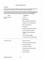
SAFETY PRECAUTIONS
The following symbols appear in this manual to call attention
to and emphasize conditions potentially dangerous to the
operator.
•
Use Extreme Care When Handling Engine Fuel
(A constant danger of explosion or fire exists)
Do not fill fuel tank(s) while the engine is running,
~WARNINGII
Do not smoke or use an open flame near the engine or the
fuel tank.
The above symbol is used in the manual to warn of possible
serious personal injury or loss of Hfe,
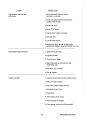
•
Be sure all fuel supplies have a positive shut-off valve.
CAUTION
Be certain fuel line fittings are adequately tightened and
free of leaks,
The above symbol is used in the manual to caution personnel
of possible damage to equipment.
Make sure a fire extinguisher is installed nearby and is
properly maintained. Be familiar with its proper use. Ex~
tinguishers rated ABC by the NFPA are appropriate for all
applications encountered in this environment.
Read the manual carefully and thoroughly before attempting
to operate the equipment. Know when dangerous conditions
can exist and take necessary precautions to protect personnel
and equipment.
Fuels, exhaust gases, batteries, electrical equipment, and
moving and hot parts are potential hazards that could result in
serious personal injury or death, Follow recommended proce~
dures carefully.
•
Lead acid batteries emit hydrogen, a highly~explosive gas,
which can be ignited by electrical arcing or by a lighted
cigarette, cigar, or pipe. Do not smoke or allow an open
flame near the battery being serviced, Shut off all electrical equipment in the vicinity to prevent electrical arcing
during servicing.
Prevent Electric Shock
Shut off electric power before accessing electrical equipment.
Use insulated mats whenever working on electrical equip·
ment.
Make sure your clothing is dry, not damp (particularly
shoes), and keep your skin surfaces dry when handling
electrical equipment.
Remove wristwatch and jewelry when working on electrical equipment.
Do not connect utility shore power to vessel's AC circuits,
except through a ship-to-shore double-throw transfer
switch, Damage to vessel's AC generator may result if this
is not done.
Be extremely careful when working on electrical
ponents. High voltage can cause injury or death,
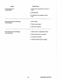
•
Use Extreme Care When Servicing Batteries
Wear rubber gloves, a rubber apron, and eye protection
when servicing batteries.
Always operate bilge blowers for at least five minutes before
starting a gasoline-fueled engine; ensure no gasoline fumes are
present before starting.
•
Do Not Alter or Modify the Fuel System
•
Avoid Moving Parts
Do not service the unit while the unit is running; if a situation arises in which it is absolutely necessary to make
operating adjustments, use extreme care to avoid moving
parts and hot exhaust system components.
Do not wear loose clothing or jewelry when servicing
equipment; avoid wearing loose jackets, shirts or sleeves,
rings, necklaces, or bracelets that might be caught in
moving parts.
Make sure all attaching hardware is properly tightened.
Keep protective shields and guards in their respective
place at all times.
com~
Exhaust Gases Are Toxic
Ensure that the exhaust system is adequate to expel gases
discharged from the engine. Check exhaust system
regularly for leaks and make sure the exhaust manifolds
are securely attached and no warping exists,
Be sure the unit and its surroundings are well-ventilated.
Do not check fluid levels or the
the unit is operating.
drive~belt's
tension while
Do not work on the equipment when mentally or physically incapacitated by fatigue.
IMPORTANT
PRODUCT SOFTWARE DISCLAIMER
Product software of all kinds, such as brochures, drawings, technical data, operator's and workshop
manuals, parts lists and parts price lists, and other information, instructions and specifications provided from
sources other than Westerbeke, is not within Westerbeke's control and, accordingly, is provided to Westerbeke customers only as a courtesy and service. WESTERBEKE CANNOT BE RESPONSIBLE FOR THE
CONTENT OF SUCH SOFTWARE, MAKES NO WARRANTIES OR REPRESENTATIONS WITH RESPECT
THERETO, INCLUDING THE ACCURACY, TIMELINESS OR COMPLETENESS THEREOF, AND WILL IN NO
EVENT BE LIABLE FOR ANY TYPE OF DAMAGES OR INJURY INCURRED IN CONNECTION WITH, OR
ARISING OUT OF, THE FURNISHING OR USE OF SUCH SOFTWARE.
For example, components and subassemblies incorporated in Westerbeke's products and supplied by
others (such as engine blocks, fuel systems and components, transmissions, electrical components, pumps
and other products) are generally supported by their manufacturers with their own software, and Westerbeke must depend on such software for the design of Westerbeke's own product software. Such software
may be outdated and no longer accurate. Routine changes made by Westerbeke's suppliers, of which
Westerbeke rarely has notice in advance, are frequently not reflected in the supplier's software until after
such changes take place.
Westerbeke customers should also keep in mind the time span between printings of Westerbeke product
software, and the unavoidable existence of earlier, non-current Westerbeke software editions in the field.
AddITionally, most Westerbeke products include customer-requested special features that frequently do not
include complete documentation.
In summation, product software provided with Westerbeke products, whether from Westerbeke or other suppliers, must not and cannot be relied upon exclusively as the definitive authority on the respective product.
It not only makes good sense but is imperative that appropriate representatives of Westerbeke or the supplier in question be consulted to determine the accuracy and currency of the product software being consulted by the customer.
1
Westerbeke Generators
FOREWORD
Thank you for selecting a Westerbeke marine product for your use. We at Westerbeke are pleased to have
you as a customer.
Read this manual carefully and observe all safety precautions included throughout. Operating procedures,
periodic preventive maintenance procedures, installation checks, system descriptions and minor adjustment procedures are included herein so you can operate your equipment safely and properly, maintain the
equipment at a high level of efficiency, and expect dependable performance and long service life in return.
Should your unit require special attention, contact your Westerbeke dealer for assistance. The Westerbeke
Service Organization is trained to provide the support necessary to ensure long-term dependable performance.
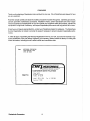
If, within 60 days of submitting the Warranty Registration Form for your unit, you have not received a Customer Identification Card (see below) registering your warranty, please contact the factory in writing with
Model information, including the unit's serial number and commission date.
from:
WESTERBEKE CORPORATION
AVON INDUSTRIAL PARK
AVON. NA 02322
f-VV-I
WESTERBEKE
:::;,:.;:::::~. ::::'.::,7~::.:;;;~ :.::: ~.::~:::.n_
CUSTOMER IDENTIFICATION
Adam S"ith
Mail To:
as
Maple Street
Alden. IN 12234
Model
BeG 4.0KW
Expires 717189
Westerbeke Generators
2
Ser. I 1234(706
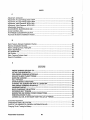
TABLE OF CONTENTS
Section ......................................................................... Page
GENERAL ........................................................................... 5
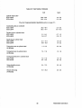
BCG 4.0KW GENERAL SPECIFICATIONS ..................... 10
BCG 4.0KW SYSTEM SPECIFICATIONS ........................ 11
BCG 6.5KW GENERAL SPECIFICATIONS ..................... 14
BCG 6.5KW SYSTEM SPECIFICATIONS ........................ 15
INSTALLATION CHECKS ................................................ 18
DESCRIPTION OF ENGINE
CONTROL PANEL. ........................................................... 31
PREPARATIONS FOR STARTING ................................... 33
STARTING PROCEDURE ................................................ 34
STOPPING PROCEDURE ................................................ 36
CARBURETOR AND FUEL SYSTEM ............................... 38
ELECTRICAL SYSTEM ..................................................... 41
DC CONTROL CIRCUIT
WIRING DIAGRAM # 37190 ................................... .44 & 45
OPTIONAL REMOTE START PANEL
WIRING DIAGRAM # 35706 ............................................ 46
OPTIONAL REMOTE INSTRUMENT PANEL
WIRING DIAGRAM # 35698 ............................................ 47
COOLING SySTEM .......................................................... 48
LUBRICATION SYSTEM .................................................. 54
BC GENERATOR .............................................................. 57
GENERAL INFORMATION AND CARE
OF THE GENERATOR ..................................................... 64
ENGINE TROUBLESHOOTING ....................................... 66
MAINTENANCE & ADJUSTMENTS ................................. 70
3
Westerbeke Generators
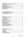
TABLE OF CONTENTS
(CONTINUED)
LAY-UP & RECOMMISSIONING ......................................80
SPARE PARTS LIST ..........................................................83
TABLE OF STANDARD HARDWARE
TIGHTENING TORQUES ..................................................84
TABLE OF TIGHTENING TORQUES ...............................85
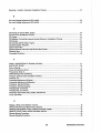
INDEX ................................................................................86
Westerbeke Generators
4
GENERAL
Introduction
This manual contains the equipment operating procedures as well as additional information needed to help
the operator keep the marine equipment in proper working order. Study and follow the instructions carefully. A planned maintenance program is included in this manual; adhering to the program will result in better
equipment performance and longer equipment life. Proper diagnosis of a problem is the most important
step to satisfactory repair; therefore, a troubleshooting table is included.
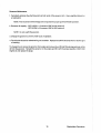
Understanding the Gasoline Engine-Driven Generator
The gasoline engine driving an AC generator is in many ways similar to a gasoline automobile engine. The
cylinders are vertical in-line, and the engine's cylinder head has an overhead camshaft which is belt-driven.
The engine utilizes conventional points and a condenser-type distributor which is horizontally mounted and
camshaft-driven. The engine incorporates a pressure-type lubrication system, and a fresh water-cooled engine block which is thermostatically-controlled. To a large degree, the generator's engine requires the same
preventive maintenance that is required of a gasoline automobile engine. The most important factors to the
generator's longevity are proper ventilation, maintenance of the fuel system, ignition system, cooling system, lubrication system and the AC end.
Ordering Parts
Whenever replacement parts are needed, always provide the generator model number, engine serial number, and generator serial number as they appear on the scarlet and gold name plate located on the generator end. You must provide us with this information so we may properly identify your generator set. In
addition, include a complete part description and part number for each part needed (see the separately furnished Parts list). Also, be sure to insist upon Westerbeke factory packaged parts, because "will fit" or
generic parts are frequently not made to the same specifications as original equipment.
Note that component locations in the manual are referenced from the front of the engine which is the pulley/drive belt end. (The flywheel/generator end is the rear end.) Left and right sides are determined by the
engine; imagine straddling the engine and facing in the same direction as the front of the engine: the left side
is at your left, the right side at your right.
Westerbeke generators sets are thoroughly checked and given a final run under various load conditions
before leaving the factory. Test running the generator ensures dependable operation, long service, and a
satisfied owner.
Care at the factory during assembly and thorough testing have resulted in a Westerbeke gasoline enginedriven generator capable of many thousands of hours of dependable service. However, what the manufacturer cannot control is the treatment the unit receives in the field. That part is up to the owner/operator.
5
Westerbeke Generators
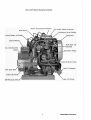
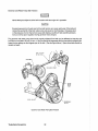
BeG 4.0KW Marine Gasoline Generator
Lube Oil Fill
Fresh Water Coolant Fill
Exhaust Mani
Lube Oil Dipstic
0
90 Exhaust Elbow
20 Amp DC Circu
Breaker
Zinc Anode
DC Battery Ground
Connection
Heat Ex.cha
Weslerbeke Generators
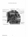
BCG 4.()KW Marine Gasoline Generator
Water Tempe ratu re Switch
Intake Flame Arrestor
rburetor with Choke
Fresh Water Air Bleed
r.;,w'''nor
Control Pane
Fuel Shut-off
Solenoid
AC
Lube Oil Drain Hose
Exchanger
Unit Data Tag
Fuel Lift Pum
Lube Oil Filter
Oil Pressure Switch
7
Westerbeke Generators
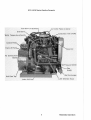
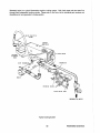
BeG S.5KW Marine Gasoline Generator
Top Engine Oil Fill
Distributor
Fresh Water Coolant Fill
Model Data
0" Exhaust Elbow
Exhaust Temperature
h
Lube Oil Dir>stick
20 Amp DC Circuit
Battery Ground
Connection
Starter with Solenoid
Westerbeke Generators
BeG 6.SKW Marine Gasoline Generator
Fuel Shut-oil So,lelnoi,d
Intake Flame Arrestor
Carburetor with Choke
Water Temperature Switc
Control
Governor
AC
Pressure Switch
Anode
Heat Exchanger
Lube Oil Drain Hose
Lube Oil Filter
9
Westerbeke Generators
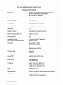
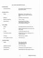
BCG 4.0KW MARINE GASOLINE GENERATOR SET
GENERAL SPECIFICATIONS
Engine Type
Gasoline, four-cycle, two-cylinder, fresh water-cooled
Vertical, in-line overhead valve mechanism
(8 hp at 1800 rpm, maximum).
Governor
Hoof, flyball type, 5% speed regulation
Combustion Chamber
Multi-sphere type
Bore & Stroke
2.82 x 2.68 inches (71.6 x 68 mm)
Piston Displacement
33.4 cubic inches (1.07 liters)
Firing Order
1-2
Direction of Rotation
Clockwise, when viewed from the front
Maximum Torque (at 1800 rpm)
33 Ib-ft (4.91 kg-m)
Compression Ratio
9.2:1
Compression Pressure
(Limit of difference between cylinders)
177.8 psi (12.5 kg/cm2) at 400 rpm
(28 psi [2.0 kg/cm2 ])
Valve Timing
Intake Opens 21' BTDC
Intake Closes 59' ABDC
Exhaust Opens 59' BBDC
Exhaust Closes 21' ATDC
Valve Seat Angle
Intake 45'
Exhaust 45'
Valve Clearance
(engine cold)
Intake 0.008 inches (0.20 mm)
Exhaust 0.010 inches (0.25 mm)
Engine Speed
1800 rpm 60 Hertz
1500 rpm 50 Hertz
Dimensions
Height: 23.00 inches (584.20 mm)
Width: 18.75 inches (476.25 mm)
Length: 25.00 inches (647.70 mm)
Weight
3091bs (140.1 kgs)
Fuel Consumption
0.8 U.S. gph (3.02 Iph) at full rated ou1put (approximate)
Inclination
Continuous 14'
Temporary 20' (not to exceed 20 min.)
Weslerbeke Generators
10
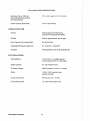
BCG 4.0KW SYSTEM SPECIFICATIONS
INTAKE SYSTEM
Carburetor (STD type)
Down draft type, single barrel with U.S.C.G.
approved flame arrester.
IGNITION SYSTEM
General
Battery ignition, 12-Volts, negative ground,
distributor with points, ignition coil and spark
plugs.
Distributor
Conventional, contact-point type
Spark Plug Thread Size
14 mm x 1.25 pitch
Spark Plug Type
Westerbeke part number 035666
(Always identify the generator model
when ordering parts. See page 5.)
FUEL SYSTEM
General
Conventional carburetor type with fuel lift pump
Fuel
Regular or unleaded gasoline with an octane rating
of 89 or higher.
Lift Pump
12-Volt DC; lift capacity 6 ft (1.8 m)
Fuel Screens (on engine)
Reusable screen type (one in Carburetor and one
in electric fuel pump).
Air cleaner
Metal screen type - cleanable
Air Flow (engine combustion)
18 cfm (0.509 cmm)
COOLING SYSTEM
General
Fresh water-cooled block,
thermostatically-controlled
with a heat exchanger.
Operating Temperature
130 - 150' F (55 - 66' C)
Fresh Water Pump
Centrifugal type, metal impeller, belt-driven
Sea Water Pump
Positive displacement, rubber impeller, belt-driven.
11
Westerbeke Generators
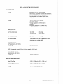
BeG II.OKW SYSTEM SPECIFICATIONS
Sea Water Flow, at 1800 rpm
(measured before discharging
into exhaust elbow)
3.75 - 11.0 U.S. gpm (14.19 - 15.14Ipm)
System Capacity (fresh water)
3.3 U.S. qts (3.2 liters)
LUBRICATION SYSTEM
General
Pressure type by Trochoid pump,
chain-driven through balance shafts.
Oil Filter
Full flow, paper element, spin-on type
Sump Capacity (not including filter)
3,0 qts (2.9 liters)
Operating Oil Pressure (engine hot)
50 - 70 psi (3.5 - 4.9 kg/cm )
Oil Grade
API specification of SD or SE, preferably SF
2
ELECTRICAL SYSTEM
Starting Battery
12-Volt, 26 A-H, (-) negative ground
(recommended) (35 A-H in cold areas)
Battery Capacity
90 - 125 (Ampere-Hours)
DC Battery Charger
Internal regulator 13 Volts, 0 -10 Amps.
Starter
12-Volt, 1.2f<W, reduction type,
solenoid-mounted
DC No-Load Current
90 Amp (max,) at 11.5 Volts.
DC Cranking Current
175 - 200 Amps (engine cold)
Westerbeke Generators
12
BeG 4.0KW SYSTEM SPECIFICATIONS
AC GENERATOR
General
Brushless, four-pole, revolving field.
Self exciting. Capacitor saturated field excitation.
Pre-lubricated, single-bearing design.
Reconnectable 120 Volls or 120[240 Volts,
single-phase
Voltage
120 or 120[240 Volts - 60 Hertz
220 Volts - 50 Hertz.
Voltage regulation: ±5% no load to
full load.
Frequency regulation: ± 3 Hertz (5%)
no-load to fUll-load.
Rating (Volts AC)
60 Hertz (1800 rpm)
120 Volts
120[240 Volts
34 Amps
34[17 Amps
50 Hertz (1500 rpm)
220 Volts
14 Amps
AC Circuit Breaker
To be rated at 120% of the generator's rated
amperage and voltage output.
Generator Cooling
Air Requirements, (60 Hertz),
at 1800 rpm
225 elm (6.4 cmm)
NOTE: Increase air supply 15% for 50 Hertz operation (1500 rpm).
Engine Combustion Air
Requirements, (60 Hertz),
at 1800 rpm
18 cfm (0.509 cmm)
TUNE-UP SPECIFICATIONS
Spark Plug Gap
0.028 - 0.036 inches (0.70 - 0.90 mm)
Contact Point Clearance
0.016 - 0.020 inches (0.4 - 0.5 mm)
Timing
16' ± l' BTDC at 1800 rpm
13
Westerbeke Generators
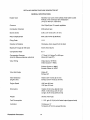
BCG S.!iKW MARINE GASOLINE GENERATOR SET
GENERAL SPECIFICATIONS
Engine Type
Gasoline, four-cycle, three-cylinder, fresh water-cooled
Vertical, in-line overhead valve mechanism
(14 hp at 1800 rpm, maximum).
Governor
Hoof, flyball type, 5% speed regulation
Combustion Chamber
Multi-sphere type
Bore & Stroke
2.99 x 2.87 inches (76 x 73 mm)
Piston Displacement
60.6 cubic inches (0.993 liters)
Firing Order
1-2-3
Direction of Rotation
Clockwise, when viewed from the front
Maximum Torque (at 1800 rpm)
40.5 Ib-It (5.6 kg-m)
Compression Ratio
9.2:1
Compression Pressure
(Limit of difference between cylinders)
177.8 psi (12.5 kg/cm ) at 350 rpm
2
(28 psi [2.0 kg/cm
Valve Timing
Intake Opens 19' BTDC
Intake Closes 51' ABDC
2
n
Exhaust Opens 51' BBDC
Exhaust Closes 19' ATDC
Valve Seat Angle
Intake 45'
Exhaust 45'
Valve Clearance
(engine cold)
Intake 0.0071 inches (0.18 mm)
Exhaust 0.0017 inches (0.18 mm)
Engine Speed
1800 rpm 60 Hertz
1500 rpm 50 Hertz
Dimensions
Height: 23.38 inches (593.85 mm)
Width: 18.69 inches (474.73 mm)
Length: 26.75 inches (679.45 mm)
Weight
3321bs (150.5 kgs)
Fuel Consumption
1.1 U.S. gph (4.16 Iph) at full rated output (approximate)
Inclination
Continuous 14'
Temporary 20' (not to exceed 20 min.)
Westerbeke Generators
14
BCG 6.5KW SYSTEM SPECIFICATIONS
INTAKE SYSTEM
Carburetor (STD type)
Down draft type, single barrel wtth U.S.C.G.
approved flame arrester.
IGNITION SYSTEM
General
Battery ignition, 12-Volts, negative ground,
distributor with points, ignition coil and spark
plugs.
Distributor
Conventional, contact-point type
Spark Plug Thread Size
14 mm x 1.25 pitch
Spark Plug Type
Westerbeke part number 033805
(Always identify the generator model
when ordering parts. See page 5.)
FUEL SYSTEM
General
Conventional carburetor type with fuel lift pump
Fuel
Regular or unleaded gasoline with an octane rating
of 89 or higher.
Lift Pump
12-Volt DC; lift capacity 6 ft (1.8 m)
Fuel Screens (on engine)
Reusable screen type (one in Carburetor and one
in electric fuel pump).
Air cleaner
Metal screen type - cleanable
Air Flow (engine combustion)
32 clm (0.906 cmm)
COOLING SYSTEM
General
Fresh water-cooled block,
thermostatically-controlled
with a heat exchanger.
Operating Temperature
130 - 1500 F (55 - 660 C)
Fresh Water Pump
Centrifugal type, metal impeller, belt-driven
Sea Water Pump
Positive displacement, rubber impeller, belt-driven.
15
Westerbeke Generators
BCG 6.SKW SYSTEM SPECIFICATIONS
Sea Water Flow, at 1800 rpm
(measured before discharging
into exhaust elbow)
3.75 - 4.0 U.S. gpm (14.19 - 15.14Ipm)
System Capacity (fresh water)
5.2 U.S. qts (4.9Itters)
LUBRICATION SYSTEM
General
Pressure type by Trochoid pump,
chain-driven through a balance shaft.
Oil Filter
Full flow, paper element, spin-on type
Sump Capacity (not including filter)
3.0 qts (2.9 liters)
Operating Oil Pressure (engine hot)
50 - 70 psi (3.5 - 4.9 kg/cm 2 )
Oil Grade
API specification of SD or SE, preferably SF
ELECTRICAL SYSTEM
Starting Battery
12-Volt, 26 A-H, (-) negative ground
(recommended) (35 A-H in cold areas)
Battery Capacity
90 - 125 (Ampere-Hours)
DC Battery Charger
Internal regulator 13 Volts, 0 - 10 Amps.
Starter
12-Volt, 1.2KW, reduction type,
solenoid-mounted
DC No-Load Current
90 Amp (max.) at 11.5 Volts.
DC Cranking Current
225 - 250 Amps (engine cold)
Westerbeke Generators
16
BCG S.5KW SYSTEM SPECIFICATIONS
AC GENERATOR
General
Brushless, four-pole, revolving field.
Self exciting. Capacitor saturated field excitation.
Pre-lubricated, single-bearing design.
Reconnectable 120 Volts or 120/240 Volts,
single-phase
Voltage
120 or 120/240 Volts - 60 Hertz
220 Volts - 50 Hertz.
Voltage regulation: ±5% no load to
full load.
Frequency regulation: ± 3 Hertz (5%)
no-load to full-load.
Rating (Volts AC)
60 Hertz (1800 rpm)
120 Volts
120/240 Volts
54 Amps
54/27 Amps
50 Hertz (1500 rpm)
220 Volts
27.8 Amps
AC Circuit Breaker
To be rated at 120% of the generator's rated
amperage and voltage output.
Generator Cooling
Air Requirements, (60 Hertz),
at 1800 rpm
250 cfm (6.23 cmm)
~: Increase air supply 15% for 50 Hertz operation (1500 rpm).
Engine Combustion Air
Requirements, (60 Hertz),
at 1800 rpm
32 clm (0.906 cmm)
TUNE-UP SPECIFICATIONS
Spark Plug Gap
0.028 - 0.036 inches (0.70 - 0.90 mm)
Contact Point Clearance
0.016 - 0.020 inches (0.4 - 0.5 mm)
Timing
14° ± 1° BTDC at 1800 rpm
17
Westerbeke Generators
INSTALLATION CHECKS
General
Since the crafts in which Westerbeke generators are installed vary in design, installation procedures will vary
according to your craft's specific design. The intent of this section is not to advise boatyards or installers on
procedures already well-developed and well-understood. However, the owner/operator must realize there
are details of the installation which require periodic checks to ensure the best operating conditions for the
equipment and safe operating conditions for the personnel on board. Proper location and installation of the
gasoline generator in the vessel are of prime importance.
Factors in the installation that must be considered are ventilation, to aid in cooling the generator end; to
provide air for engine combustion and to remove heat produced by the engine while operating; the exhaust
system, to properly discharge raw cooling water (sea water), to quiet the exhaust, and to expel exhaust gas;
the cooling water supply; and the electrical connections.
CAUTION
For safety reasons, the generator's engine is NOT filled with lubricating oil for shipment. Before
leaving the factory, however, each generator set is thoroughly tested with oil in its engine.
This testing, among other things, provides all internal parts with a coating of oil. This oil acts
as a preservative, providing reliable protection against corrosion for at least one year if the
generator is properly stored.
Inspection of Equipment
The generator is shipped from the factory securely mounted and properly crated. Accessory equipment is
shipped in a separate small box, usually packed within the generator's crate.
Before accepting shipment olthe generator set from the transportation company, the crate should be opened
and the contents inspected for concealed damage. If either visible or concealed damage is noted, you should
require the delivery agent sign "Received in damaged condition" on the proper delivery receipt. Also check
the contents of the shipment against the packing list and make sure that the proper notation is made if any
discrepancies exist. These noted discrepancies are your protection against loss or damage. Claims concerning loss or damage must be made to the carrier, not to the Westerbeke Corporation.
Westerbeke Generators
18
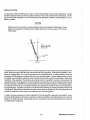
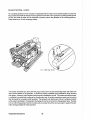
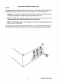
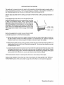
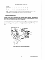
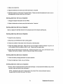
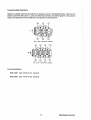
Rigging and Lifting
The generator is fitted with lifting eyes. Rope or chain slings capable of supporting the generator's weight
should be attached to the eyes and the generator lifted by means of tackle attached to these slings. The lifting eyes have been designed to carry the full weight of the generator; therefore, auxiliary slings are not required or desired.
CAUTION
Slings must not be so short as to place significant stress on the generator's lifting eyes. Strain
placed on the generator's lifting eyes by the lifting Sling must not be in excess of 100 from the
vertical plain.
SLING LIFTING
ANGLE MUST HOT
EXCEED 10'
LI FT I NG
EYE
ENGINE
The general rule in moving generators is to see that all equipment used is amply strong and firmly fixed in
place. Move the engine a little at a time and see that it is firmly supported. Eliminate the possibility of accidents by avoiding haste. Do not lift the generator by its crankshaft pulley. In certain sttuations tt may be
necessary to lift the engine in positions other than the horizontal position. Certain situations exist by which
the engine must be lowered endwise through a small hatchway which cannot be made larger. Under these
conditions, If the opening of the hatchway is extremely small, it is possible to reduce, to some extent, the
outside dimensions of the generator by removing external components such as the cooling system's piping,
the heat exchanger, certain filters, the mounting rails and other obstructive equipment. This accessory equipment should be removed by a competent mechanic and special care should be taken to avoid damage to
any exposed parts. In addttion, be careful not to allow dirt from entering any opening created by the removal
of equipment. Removed parts should be returned to their respective position as soon as the generator has
cleared the obstruction and is ready to be positioned on its mounting platform.
In case it becomes necessary to hoist the generator front-end upwards or generator-end upwards, the attachment of lifting slings must be done carefully to avoid the possibility of damaging the parts on which the
weight of the slings may bear. Special rigging work is best done by someone experienced and competent
in handling heavy machinery.
19
Westerbeke Generators
Generator Mounting - Location
The complete generator unit is mounted on lightweight rails by means of four flexible isolator mounts that
help preventthe transfer of vibration from the generator to the rails. Each generator mounting rail has several
1/2-inch bolt holes so bolts can be employed to properly secure the generator to ks mounting platform.
These holes are on 15 inch mounting centers.
(1/2- MOUNTING HOLES)
The location should be dry, above low-lying vapor areas, and in an area where bilge water and water from
above cannot splash on the generator. It should be properly ventilated and accessible for minor servicing
and repairs. Access for major repairs should be given consideration as well. The location should be properly ventilated to provide fresh cooling air for the generator end, for engine combustion needs, and to remove
heat produced by the engine while operating. The generator set needs fresh cool air in whatever location
in the vessel it is installed. Hot generator discharge air must be removed from the generator area. The platform on which the generator and ks mounting rails are located should be strong enough to support the generator during all angles of vessel operation.
Westerbeke Generators
20
Exhaust System
IIWARNINGI
CARBON MONOXIDE EXHAUST GAS IS DEADLY. Carbon monoxide is a dangerous gas that
can cause unconsciousness and is potentially lethal. Some of the symptoms or signs of carbon monoxide inhalation or poisoning are listed below.
o Dizziness
o Intense Headache
o Weakness and Sleepiness
o Vomiting
o Muscular Twitching
o Throbbing in Temples
All exhaust systems should be such that the entry of sea water into the engine's exhaust manifold and
cylinders is prevented while the engine is not running, or while the vessel is under sail or power in which case
the vessel may experience heeling or backing down from following seas or any other conditions. Special
attention must be taken to make certain the exhaust system is secure and tight and free of leaks.
The sea water supply through-hull sea cock fittings must be of the flush-hull type. High-speed scoop type
fittings must not be used, as they tend to encourage siphoning.
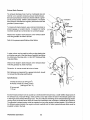
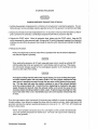
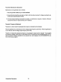
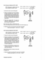
When a water lift type exhaust system is used, the exhaust muffler should be mounted as close to the engine as practical. The exhaust discharge
should always drop downward into the
exhaust muffler. Loops in the exhaust
hose between the water-injected exhaust
elbow and the water lift muffler should be
avoided, as these will trap and hold water.
For installations where the exhaust
manifold/water-injected exhaust elbow is
at or below the vessel's water line,
provisions must be made to install a
siphon-break or a vent in the sea water
supply hose to the water-injected exhaust elbow. This stops the flow of sea
water that runs through the sea water
cooling system from filling the exhaust
and engine cylinders when the engine is
shut down. This sea water supply hose
must be looped above the water line and
the siphon-break or vent installed in the
high point of the loop above the water
line. This siphon-break or vent must always be above the water line during all
angles of vessel operation to prevent
siphoning. The vent, when used, must
have its vent hose or tube routed so it can
remain above the water line and empty of
water when the engine is shut down. This
allows air to enter through this vent to
prevent siphoning.
"""u"i- I!~~ ~ ~
PUHP
HI WATER
STUIHR
GEI£RllOR Alan wtm LIU
SIPHOI utAI-----+:':
m
IIAHR
"''-'.'
PUMP
GEMEUIOR HLOII IInH LIME
21
Westerbeke Generators
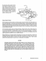
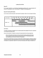
Exhaust Back-Pressure
The exhaust discharge hose must be of adequate size and
minimal run to prevent excessive exhaust back-pressure.
Exhaust back-pressure should be checked before a generator is put into service. (Refer to the illustration.) Excessive
back-pressure will affect the engine's performance and the
generator's power output.
To measure for back-pressure, use a mercury manometer, a
pressure gauge, or a water column. A boatyard or marine
mechanic should have a manometer or a pressure gauge.
Exhaust
Elbow
."
Measure the engine's back-pressure at the exhaust elbow
while the generator is under a full load.
"
"
.""
Exhaust
..
Refer to the pressure specifications listed below.
Ii ~.
Mercury
Manometer
\
A water column can be made by taking a clear plastic tube
and taping one end of the tube along a yardstick and fitting
the other end of the tube with a 1/4 inch NPT (National Pipe
Tap) pipe fitting.
Measure the engine's back-pressure at the exhaust elbow
while the generator is under a full load.
~
Dimension A cannot exceed 39 inches of water.
Back pressure, as measured by a gauge instrument, should
not exceed the following specifications:
1/.
NPT
Plug
Specifications:
3 inches of mercury (0.104 kg/cm 2)
39 inches of water in a water column
(.099 kg/cm2 at 4° C)
22 ounces psi
1 1/2 psi
\
Excessive back-pressure can be caused by a small diameter exhaust hose, a small muffler, sharp bends in
the exhaust hose, improper fittings, water pockets, and a high volume of water in the exhaust system due
to the length of the exhaust discharge hose. The use of elbows and fittings in the exhaust discharge hose's
routing should be limited since these will create flow restrictions and contribute to exhaust back-pressure.
The generator's exhaust system must be separate from any other engine's exhaust system. Dry portions of
the exhaust system between the engine's exhaust manffold and the water injected exhaust elbow must be
insulated to hold in the heat.
Weslerbeke Generators
22
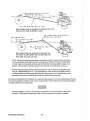
Dry stack-type exhaust systems (shown
to the right) must be attached to the generator engine's exhaust manifold by
means of a flexible connector pipe. This
system must be properly supported and
insulated to prevent water from entering
into the engine's cylinders. Provisions
must be made for discharging the
engine's cooling sea water.
FLAf'PE~
~lf
coVEN
.I
!'
I
---1
~=====14r.~,L
7'f"".M.
MUI"FLI::R
XHSUL
,I
I:
.:! :'
TJ:DN
'1 '
~
.1/2"
X.F.5.
P][I"E
PXTI: ..
EXHAUST
-
COHDr::N-;::::S;p;~i'-'
SAT:tOH
TRAP
LIHf
SE:A
WATER
%NTAKe: TIH;lOUGH_
HULL I'"1:Tl":t ....
Exhaust System Failures
DRY STACK EXHAUST
When the engine's sea water is fed into an exhaust system so that the full stream of this water strikes a surface, erosion takes place. This erosion may cause premature failures. The proper design of either a water
jacketed or water injected "wet" exhaust system to prevent this problem requires that the sea water inlet be
positioned so that the entering stream of sea water does not directly strike a surface. In addition, the velocity
of the entering sea water stream should be as low as possible, which can be achieved by having inlet fittings
as big in diameter as possible.
The best protection against carbon monoxide poisoning is a daily inspection of the complete exhaust system. Check for leaks around manifolds, gaskets, and welds. Make sure exhaust lines are not heating surrounding areas excessively. If excessive heat is present, correct the situation immediately. If you notice a
change in the sound or appearance of the exhaust system, shut down the unit immediately and have the
system inspected and repaired at once by a qualified mechanic.
Make sure there are no unnecessary objects suspended from any portion of the exhaust lines. Exhaust risers
installed off the exhaust manifold should not exceed 8 Ibs in total weight when rigidly constructed. Excessive weight could cause deflection or distortion of the lines, resulting in damage or leaks. Inspect insulated
portions of the exhaust system to ensure there is no deterioration of the insulation.
CAUTION
Prolonged cranking intervals without the engine starting can result in filling the enginemounted exhaust system with sea waler coolant. This may happen because the sea
water pump is pumping sea water through the sea water cooling system during cranking. This sea water can enter the engine's cylinders by way 01 the exhaust manifold
once the exhaust system fills. Prevent this from happening by closing the sea water
supply through-hull shut-off, drain Ihe exhaust mulller, and correct Ihe cause lor the
excessive engine cranking needed to obtain a start. Engine damage resulting from this
Iype of sea waler entry is nol a warrantable issue; the owner/operalor should keep this
in mind.
23
Weslerbeke Generators
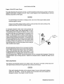
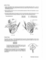
Exhaust Elbow Installation
The Westerbeke Corporation offers a 45°and 900 exhaust
elbow as well as an exhaust riser you can install on your
generator. Refer to the instructions below when installing
the exhaust elbow purchased for your generator.
1. Coat only one side of the exhaust gasket with ·"High
Tack" adhesive sealant. Place this coated surface
against the exhaust manifold's exhaust port flange (the
gasket should stick to the flange without falling off).
2. Place the clamp over the elbow's flange. Place your exhaust elbow against the exhaust manifold's flange so
the exhaust manifold's flange rests snug against the exhaust elbow's flange with the gasket centered between
the two. Now slip the exhaust clamp over both flanges.
CLRMP
45° ELBOW
3. A. Tighten the clamp just enough so the exhaust elbow
can remain attached to the manifold and still be
rotated.
B. The exhaust elbow discharge must be directed
downward so the miXiure of sea water and exhaust
gases will flow/fall downward into the exhaust muffler which must be positioned below the exhaust
elbow. There should be no loops or rises in the exhaust hose connected between the exhaust elbow
and the muffler, as these would trap water and possibly allow water to flow back into the engine during
starting or at shut down.
CLAMP
90· ELBOW
4. Adjust the elbow by rotating it until the desired aJignment with the exhaust piping is acquired.
5. Carefully tighten the clamp between 2 to 3 Ib-ft, or 24
to 35 Ib-in, or 0.27 to 0.41 kg-m.
CAUTION
Approach the :3 II>-It torque limit with caution.
The clamp's threads will break if more than 3 lI>ft is applied to Ihe clamp.
If a leak exists, correct it immediately.
* Manufactured by Permatex Company, Brooklyn, N. Y.
EXHAUST RISER
ClAMP
Weslerbeke Generators
24
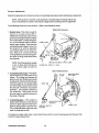
Fuel System
The generator must have its own fuel supply line; in other words, it must have fis own pickup tubes and
primary filter/water separator. DO NOT tee off another engine's fuel supply. Installations where the fuel
tank(s) are at or above the generator, with the fuel supply lines to the engine's carburetor routed below the
level of the fuel tank's top, must have a means of shutting off the fuel to the generator's engine when the engine is not running. This installation procedure helps guard against the possibility of gasoline siphoning
through the supply line into the engine through the carburetor, should the carburetor float needle valve stick
in the open position or not seat properly, or should the fuel line rupture between the engine and fuel tank.
This (anti-siphon) shut-off valve can be electrically-operated (with a manual override) to open when the generator's engine is started, and to close when the generator's engine is shut down. A manually-operated valve
can also be installed and should be operational from the generator's start/stop panel or from the vessel's
deck. Installations where the generator is located above the fuel tank(s), whereby the routing of the fuel
supply line to the generator's carburetor remains above the top level of the fuel tank, do not require this (antisiphon) shut-off valve. A manually-operated service shut-off valve should be located between the fuel pickup at the tank and the service shut -off valve located at the fuel connection to the generator.
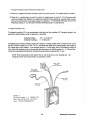
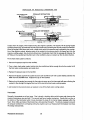
The two illustrations that follow were taken from the Coast Guard publication Fuel System Compliance
Guideline. These illustrations show basic fuel system layouts that incorporate anti-siphon protection.
All fuel lines should be routed and supported to prevent leaks from vibration and chaffing. The line should
be supported every 12 - 14 inches. Use as few connections as possible in the plumbing of these lines.
The fuel tank's vent should be located so that its discharge route cannot allow water to enter through to the
fuel tank(s). Moisture must not be allowed to accumulate in the vent's line.
FUEL LINE ALWAYS ABOVE FUEL TANK TOP LEVEL
FUEL TANK TOP LEVEL
~
-
--"..::---~~-~~.:::.-.:--:::::=:~--:-d
_'-'...\
NO ANTI-SIPHON DEVICE OR ELECTRICALLY
OPERATED VALVE HEEDED
NOT ACCEPTABLE
FUEL
FUEL TANK TOP LEVEL
25
Westerbeke Generators
.~
~
---
AMTI-SIPHON DEVICE OR ELECTRICALLY
OPERATED FUEL STOP VALVE
--~~~)"""";-:::";-:::::~/~-7::~~~F~U~E~L~TA~N~K~T:o:p~L~E~V:E~L~:/""~~i~~~~""","'-I
FUEL LINE BELOW FUEL TANK lOP LEVEL
ANTI-SIPHON DEVICE OR ELECTRICALLY OPERATED FUEL STOP
VALVE AT fUEL TANK WITHDRAWAL FITTING
I
fU EL TANK lOP LEVEL
~
ANTI-SIPHON DEVICE OR ELECTRICALLY
OPERATED FUEL STOP VALVE
FUEL LIKE ABOVE FUEL TANK
T OP
lE~V~EL~;_~=-~~.::::.~=:::~=:~
fUEL LINE BELOW fUEL TANK
TOP LEVEL
ANTI-SIPHON DEVICE OR ELECTRICALLY OPERATED FUEL
STOP VALVE AT POINT WHERE FUEL DISTRIBUTION LINE
GOES BELOW FUEL TANK TOP LEVEL
NOTE: The use of mechanical spring-type check valves instead of a solenoid shut-off valve is
not recommended, since these may tax the fuel lift pump's ability to draw fuel through them.
A check valve can trap debris under its seat which inhibits the valve's ability to close. In addition, if a check valve's cracking pressure is 100 high, this can contribute to vapor lock.
Should a mechanical type, spring-loaded check valve be used, it should be an adjustable type,
such as a Weatherhead #43 x 6. This adjustable type valve should be adjusted to have a
cracking pressure that will prevent siphoning when the generator is not operating but not so
excessive as to prevent the fuel lift pump from drawing fuel through the valve.
Strongly recommended is the installation of an approved filter/separator in the fuel supply between the fuel
tank and the generator's engine to help remove contaminants in the fuel before the fuel reaches the enginemounted fuel lift pump and carburetor.
IWARNING\
Gasoiine ieakage in or around the generator compartment is a potential cause of fire and/or
explosion. Repair leaks promptly and make sure the compartment is property ventilated.
Westerbeke Generators
26
Oil Drain Hose
An oil sump drain hose is installed on the engine with the discharge end secured by a bracket at the front 01
the engine. Oil may be drained from this hose by removing the cap and the discharge end of the hose from
the support bracket and lowering the hose into a container. The hose cap fitting is 1/4 inch NPT (National
Pipe Tap) and can be extended, or have a pump added, for easier removal of the old oil, if desired.
Connecting Pressure Sensing lJevices to Oil Galleries
Oil pressure sensing devices, such as senders and switches, must not be connected to an engine's oil gallery with the use of extended nipples or tees. The reason is simply that continued engine vibration causes
fatigue of the fittings used to make such a connection. If these fittings fail, the engine loses its oil pressure
and quickly seizes.
When additional sensing devices such as switches or sensors need to be installed that function on engine
oil pressure, these devices must be bulkhead-mounted and connected to the oil gallery using an appropriate
grade of lubricating oil hose. Any fittings used to connect the hose to the gallery must be of steel or malleable iron composition. Brass must not be used for this application.
Sea Water Intake System
Make sure the intake system (sea water cooling system) is in proper order. Check that the hull inlet, sea
cock and strainer are unobstructed. Sea cocks and strainers should be at least one size greater than the
inlet thread of the sea water pump. The strainer should be of the type that may be withdrawn for cleaning
while the vessel is at sea and should be mounted below the water line to ensure self-priming. Inspect the
sea water lines to make sure there are no collapsed sections, which would restrict water flow. Make sure
there are no air leaks at any of the connections.
Cooling System
The generator's engine is fresh water-cooled by an enginemounted heat exchanger. Sea water is used as the heat
exchange's cooling medium. Sea water is pumped into
the exchanger by a sea water pump and is then injected
into the exhaust discharge, carrying with it the heat
removed from the engine's fresh water cooling system.
Sea water should be supplied to the sea water pump
through a flush-type through-hull fitting using a wire-reinforced hose between the through-hull fitting and the sea
water pump. This sea water should be directed through a
visual-type sea water strainer and then delivered to the
pump. Hoses routed from the through-hull fitting to the
strainer and to the sea water pump should be wire-reinforced to prevent the hose from collapsing during the generator's operation (suction from the pump may collapse a
non-reinforced hose). Sea water strainers should be
mounted at or below the water line to make sure the sea
water line remains primed.
27
BElT TENSION
3/8-112 INCH
DEFLECTION AT
LONGEST SPAN
Weslerbeke Generators
CAUTION
DO NOT use a scoop-type through-hull fitting as a means of supplying sea water to the generator. Water pressure against this type fitting, while the vessel is under way, can push sea
water past the sea water pump's impeller into the generator's exhaust system, filling it and the
engine as well. Flush-type, clear, through-hull fittings are recommended and should be located on the hull so as to be below the watertine during all angles of boat operation.
The use of common-type street elbows is not recommended for plumbing the sea water circuit. These
generally have very restrictive inside diameters. Machined fittings with true inside diameters are preferred.
Electrical System
The electrical system should be checked to make sure all wiring harnesses are property tied down with
clamps or plastic ties and that all wiring harnesses are spaced at intervals close enough to prevent chafing
from vibration. Check to make sure all engine harness connections are tight and that they are made to the
appropriate terminals.
DC Electrical Connections
A common ground for the negative (-) DC terminal connection is found at the bell housing of the generator,
next to the starter, in the form of a threaded grounding stud. The battery ground should be connected at
this stud.
Connect the battery's positive (+) connection to the starter solenoid tagged for this connection.
CAUTION
To avoid an overcharging condition, and a possible equipment failure, DO NOT disconnect
the DC battery source while the engine is running.
Grounding
The generator set must be grounded to comply with United States Coast Guard regulation 33 CFR-183 which
specifies that a common conductor be connected between the generator set and the vessel's main propulsion engine's grounded starter motor circuit. This conductor (the common ground) prevents accidental passage of cranking current through fuel systems and smaller electrical conductors common to the engines.
This conductor must be the same size as the largest battery cable.
Automatic Shutdown
High Exhaust Temperature Shutdown Switch (normally closed)
An exhaust temperature switch is located on the exhaust elbow. This switch will open and interrupt the DC
voltage to the ignition coil (which turns OFF the engine), should the switch's sensor indicate an excessive
exhaust temperature (an inadequate supply of sea water coolant causes high exhaust temperatures). This
switch opens at 260 - 270 0 F (127 -1320 C) and resets at approximately 2250 F (1070 C).
Westerbeke Generators
28
High Water Temperature Shutdown Switch (normally closed)
A high water temperature switch is located on the thermostat housing. This switch will open and interrupt
the DC voltage to the ignition coil (which turns OFF the engine), should the fresh water coolant's operating
temperature reach approximately 205' F (96' C). This switch resets at 195' F (107' C).
Low Oil Pressure Shutdown Switch (normally open)
A low oil pressure shutdown switch is located off the engine's oil gallery. The switch's is kept closed bye
engine oil pressure. Should the engine's oil pressure fall to 10 - 15 psi, the switch will open interrupting the
DC voltage to the ignition coil (which turns OFF the engine).
High RPM Shutdown Switch
An overspeed shutdown switch shuts OFF the generator set by grounding out the ignition system should
the engine's speed reach approximately 2175 rpm. Reset this switch by momentarily depressing the STOP
switch. (Make sure the cause of the engine overspeed shutdown is corrected.)
Generator (AC Outpul)
Make sure that the AC output connections within the generator's distribution box are tight and in accordance with the specific AC Load Connections diagram found later in this manual. (See the "BC GENERATOR"
section of this manual, page 57.)
Batteries
Make sure the positive ( + ) battery connection is connected to the battery connection of the starting solenoid.
The negative (-) battery connection should be connected to the system ground (the engine block).
IWARNINGI
Do not smoke or allow an open flame near batteries. Lead acid batteries emit hydrogen, a
highly-explosive gas.
IWARNINGI
When servicing the battery or checking the electrolyte level, wear rubber gloves, a rubber
apron, and eye protection. Battery acid may splash on the skin or into the eyes inadvertently when removing the electrolyte caps.
Check the battery's electrolyte level and specific gravity to ensure maximum engine starting efficiency. Make
sure the battery's terminals are clean and tight.
29
Westerbeke Generators
Ventilation
The ventilation requirements of the generator sets include the following: combustion air is required for the
engine cylinders; cooling air is required for the generator end and also lor removing the heat produced by
the generator's engine during operation; and ventilating air is required to clear the bilges below the generator, as well as the compartment in which the generator is located, of potentially toxic and flammable gasoline
vapors.
Keep in mind that hot air rises, so heated air should be removed from the upper area of the generator compartment and cool fresh air should be directed to the lower areas of the compartment. Ventilation should
be accomplished with the aid of blowers especially when the vessel is not underway. Refer to the "SYSTEM
SPECIFICATIONS" section 01 this manual for the airflow requirements of the generator sets, page 13 for the
BCG 4.0KW, and page 17 for the BCG 6.5KW.
Westerbeke Generators
30
DESCRIPTION OF ENGINE CONTROL PANEL
General
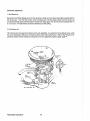
The engine-mounted control panel is equipped with an ON switch, a START switch, and a STOP switch. The
panel also has three fuses to protect the circuit. The three switches serve the following functions:
1. ON Switch· The ON switch provides power to the START circuit. This switch also bypasses the protective oil pressure shu1down switch until the engine's oil pressure reaches 15 psi.
2. START· The START switch energizes the starter's solenoid which cranks the engine. This switch will
not operate unless the ON switch is depressed and held at the same time.
3. SIQE: The STOP switch is used to stop the generator. This switch must be depressed until the generator comes to a complete stop.
The engine-mounted control panel is protected by three fuses. The F1 ignition circuit and the F3 panel circuit are protected by individual 8 Amp fuses. The F2 starter circuit is protected by a single 15 Amp fuse.
31
Westerbeke Generators
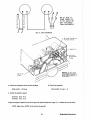
Optionsl Remote instrumenlllnd Remote Start Panels
An optional remole instrument panel is available, which includes starting controls. This panel also includes
a water temperature gauge, oil pressure gauge, battery voltmeter, operating hourmeter and start-stop control switches.
REMOTE START
REMOTE INSTRUMENT PANEL
PANEL
IWARNINGI
When installing the optional remote start panel or the optional remote instrument panel, IT is
the installer's responsibility to comply with U.S. Coast Guard Standards 33 CFR PART 183.
An optional remote start panel is available for controlling the generator from a remote location.
Remote start panels include a green LED which lights when the engine runs at approximately 600 rpm. The
purpose of the LED is to alert the operator to release the starter toggle switch in addition to continue indicating that the generator set is running.
Westerbeke Generators
32
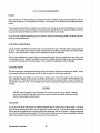
PREPARATIONS FOR STARTING
This section of the manual provides the operator with preparation, initial starting, break-in, starting (cold or
warm), and stopping procedures. Follow the procedures as presented, for the conditions indicated, and
your Westerbeke generator set will give you reliable performance and long service life.
Take the steps described below in starting your engine for the first time or after a prolonged shutdown or
lay-up.
Fill your engine with oil up to but not over the upper limit on the
dipstick (the installation angle of your generator set may have
an effect on the dipstick reading). Select a readily available
lubricating oil with an API specification of SD, SE or SF and an
SAE number suitable forthe temperature in your operating area
(see page 54). Forthe quantity of oil needed in your generator's
engine, referlo the "SYSTEM SPECIFICATION" section of this
manual, page 12 for the BCG 4.0KW, and page 16 for the BCG
6.5KW.
upp ER LIM! T
(NORMRL
LEVEL)
LOWER LIMIT
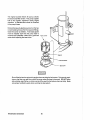
Each unit is supplied with a coolant recovery ktt (part #24977)
as standard equipment, to which the following applies:
A. Remove the pressure cap from the engine's exhaust manifold and slowly fill the engine's cooling system with a mixture of water and antifreeze suitable for your temperature zone. (See the "COOLING
SYSTEM" section of this manual, page 49.) Replace the pressure cap on the manifold.
B. Make sure the plastic recovery tank is properly mounted near the unit (with the bracket provided) in a
location where it can be monitored and filled easily (see page 49). The recovery tank should be mounted
at manifold level or above.
C. Coolant should be added to the plastic recovery tank after the engine has been filled and started. After
its operating temperature has been reached, make sure all air is expelled out of the engine's manifold
and the engine's cooling system. With the manifold filled and the pressure cap installed, fill the plastic
recovery tank half full. Monitor this recovery tank daily and add coolant as needed.
Fill the fuel tank with unleaded or leaded gasoline that has an octane rating of 89 or higher.
Make sure the Installation Checks have been made in accordance with those specified in the "INSTALLATION CHECKS" section of this manual (refer to page 18) and that there is no AC load on the generator.
JJ
Westerbeke Generators
STARTING PROCEDURE
IWARNINGI
CARBON MONOXIDE EXHAUST GAS IS DEADLY
1. Ventilate the generator compartment for a minimum of 5 minutes prior to starting the generator. The ventilating blowers remove potentially explosive gasoline fumes from the generator compartment and bilge.
2. Depress the ON SWITch and hold it depressed for 5 to 15 seconds to make sure the fuel system on the engine is primed to the carburetor. Continuing to depress the ON switch, proceed to step #2.
3. Depress the START switch. When the generator starts, release only the START switch. Keep the ON
switch depressed for a few seconds longer. (Keeping the ON switch depressed bypasses the oil pressure
shutdown circuit until the oil pressure rises enough to close the switch internally and maintain the ignition
circuit.)
4. Release the ON switch.
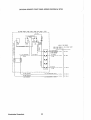
NOTE: The engine has an electric choke which is activated when the ON SWITch is depressed
and while the engine is operating.
CAUTION
When starting the generator, all AC loads, especially large motors, should be switched OFF
until the engine has come up to speed and, in cold climates, starts to warm up. This precaution will prevent damage caused by the unanticipated operation of AC machinery and will
prevent a cold engine from stalling.
CAUTION
Prolonged cranking intervals without the engine starting can result in filling the enginemounted exhaust system with sea water coolant. This may happen because the sea
waler pump is pumping sea water through the sea waler COOling system during cranking. This sea water can enter the engine's cylinders by way ollhe exhaust manifold
once the exhaust system fills. Prevent this from happening by closing the sea water
supply through-hull shut-off, drain the exhaust muffler, and correct the cause for the
excessive engine cranking needed 10 obtain a start. Engine damage resulting from this
type 01 sea waler entry is not a warrantable issue; the owner/operator should keep this
in mind.
Once the engine starts, check instruments (if instruments are installed) for proper oil pressure and battery
charging voltage. Never attempt to engage the starter while the engine is running. Apply a light load to the
generator and allow the engine's operating temperature to come up to 110 - 120' F (44 - 49' C) before applying any heavy loads.
NOTE: Some unstable running may occur in a cold engine, but this condition should smooth
out as the operating temperature is reached (130 -150' F [55 - 66' Gj) and when a load is applied to the generator.
Westerbeke Generators
34
Remote Starling Procedure
The remote start panel is the same as the engine-mounted start panel except that it has a green LED light.
When starting at a remote location, the green LED lights when the generator is running at approximately 600
rpm, which indicates when the START switch can be released, since the starting of the generator may not
be audible.
A. When starting the generator set at a remote location, release the START switch when the green LED
lights, but continue depressing the ON switch. After releasing the START switch, continue holding the
ON switch until the oil pressure is sufficient to close the oil pressure safety switch, providing the normal B + path to the ignition system.
B. After the generator is started, the generator's starter will not crank until someone again operates the
ON switch first.
Remote Stopping Procedure
To STOP the generator, depress the STOP switch, which opens the normally closed B + path for voltage to
the engine's ignition circuit. The STOP switch must be held open until the generator comes to a complete
stop. Remote start panels may be connected to the generator set as indicated. A jumper has to be removed
between the T-1 and T-2 connections at the panel connection terminal board. (Refer to the wiring diagram
in the "ELECTRICAL SYSTEM" section of this manual, page 44, lower left-hand corner.)
Overspeed Shutdown
Should the generator shut down from an overspeed condition, the overspeed circuit must be reset before
atternpting to restart the generator. Resetting the overspeed switch is done by simply depressing the STOP
switch momentarily and then proceeding with the normal starting procedure.
If the overspeed switch itself is faulty and resetting it by depressing the STOP switch will not reset the circuit,lifttheT-l coil connectionlromthe swttch and tape the end of the T-l wire with electrical tape. DO NOT
operate the generator with the overspeed switch bypassed. Bypass this circuit only to lest the overs peed
circutt. Replace the overspeed switch to maintain this safety circuit's integrity.
The overspeed shutdown must always be installed and functioning. Any tampering with the
overspeed shutdown module, which would cause it to malfunction, could be a cause of injury
should the generator's belt-driven governor fail and cause the generator to run away.
35
Westerbeke Generators
STOPPING PROCEDURE
1. Remove the AC electrical load from the generator and allow the generator to run for 3 to 5 minutes to stabilize its operating temperatures.
2. Depress the STOP switch and hold it until the generator is completely stopped.
3. Now release the STOP switch.
Break-In Precautions
Because the generator set operates at 1800 rpm to produce 60 Hertz, or at 1500 rpm to produce 50 Hertz,
control of the generator's engine break-in is governed by the current drawn from the generator.
DO NOT attempt to break-in your generator set by running it without a load.
Upon starting the generator set, check for proper operation. For the first 10 hours of the generator's operation, run the generator set between 20 and 60 percent of full-load.
After the first 10 hours of the generator's operation, the load may be increased to the rated full-load output.
Periodically vary the load.
Avoid overload at all times. An overload is signalled by a smoky exhaust, with reduced output voltage and
frequency. Monitor the current being drawn from the generator and keep it within the generator's rating.
Be aware of motor starting loads and the high current draw required for starting motors (see page 64 for an
"Amps for Starting" chart).
Starting Under Normal Conditions
Follow the procedure below for routine starting of the generator:
Check the engine's lubricating oil level prior to each day's use. Add oil as needed and maintain the oil level
at the high mark on the dipstick.
Check the coolant level in the plastic recovery tank.
NOTE: Excessive loss of fresh water coolant from the plastic recovery tank indicates a cooling system leak. Check the entire cooling system; pressurize the system to locate the leak.
In cases of excessive coolant loss, the system must be refilled as outlined under the
"PREPARATIONS FOR STARTING" section of this manual, page 33.
Visually examine the unit; look for any abnormalities and correct them as needed.
Check to make sure there is sufficient fuel in the tank and examine the filter/separator bowls lor contaminants.
Clean and drain the bowls as needed.
Start the generator, following the procedure outlined in the "STARTING PROCEDURES" section, page 34,
and allow the engine's operating temperature to reach 130 -150' F (55 - 66' C) before placing the generator
under a heavy load.
Westerbeke Generators
36
Starting Under Cold Conditions
Under extremely cold temperatures, the following conditions can occur. Follow the instructions listed below
when operating your generator set in cold weather.
LUBRICATING OIL TURNS VISCOUS - Make certain that the lubricating oil used conforms with the ratings
for the prevailing atmospheric temperature. Refer to the "LUBRICATION SYSTEM" section of this manual,
page 54, for an atmospheric/oil viscosity specification table.
VOLTAGE ACROSS BATIERY TERMINALS DROPS - Make certain that the battery is fully charged to minimize voltage drop across the battery terminals.
37
Westerbeke Generators
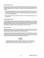
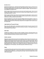
CARBURETOR AND FUEL SYSTEM
Gasoline
Use unleaded or leaded gasoline with an octane rating of 89 or better.
In cold weather particularly, water vapor is produced by condensation when air is present in the fuel tank.
Keep fuel tank(s) full and completely free of dirt and water.
The carburetor is a single barrel, down-draft type with a cleanable metal screened air intake filter/spark arrestor.
GOVERNOR
LINKAGE
/
SCREENED
AIR
CLEANER
FUEl
SOlENO 0
INLET
SCREEN
"
Westerbeke Generators
38
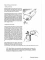
Optional Fuel Filler
INSTALLATION INSTRUCTIONS
1. BOU SEDIMEIITI\lIIIEI! iRAP SECURELY TO
HOSE FITTING
A primary fuel filter of the water entrapment type should be installed between the
fuel tank and the engine. A primary filter,
shown here, is available from your local
Westerbeke representative or your boatbuilder. This filter, adapted for the
boatbuilder's use, comes complete with
fittings for either hose or metal tubing.
Mount It in an accessible place, inspect it
often, and drain off water accumulation
frequently.
AM ACCESSIBLE STRUCTURE
so
PllsmONEB
TlIfH II RECEPTICLE TO CATCH mIlI/IS[
CIIN BE PLAtED UNDER IT.
Z. IF fUEl IS TO BE PIPED IIITII
COPPE~,
IIR IIUIID' TUBIIIG, USE NUTS AIID fERRULES
PRDUIOED. BE SURE TilE lUllING PROJECTS
1/4 fMCH THROUGH THE FERRULE BEFORE
TIGIITENIMG THE MOT.
3. If fUEL IS til BE PIPED IIlTIl HOSE, USE
TilE TWO BRASS BIIRBED FITTINGS AHO waSHERS
SUPPLIED. BE tERTRIM THRt IHE HOSE SELECTED
HAS DIIISONAL BRAID INSERTED
no
mNG ON THE
BARBI, THAT IT IS NEOPRENE LUIED. AND THAT
IT IS
TUBE PIPING
U§~~
IIPPIIOII£II.
··i..
A ..............
If a water trap type filter is not installed between the fuel tank and the enginemounted fuel system, any water in the fuel
system will tend to inhibit proper starts. In
addition, particles will pass on to the lift
pump's filter, clogging it in time.
, ....-
(
4. IF VATER IS PRESEHT III THE FUEL, IT lIIll
COLLECT 5LIIIIL' IN lin: IIOITD" Df THE
SEomIlTER. VHEN THE RED fLOAT RING
REACH£S rHE DRAIN LIKE ON TilE PLASTIC
BOWL, LOOSEN THE BOTToH DRAIN PLUS uml
ALL WATER RUIIS DUT.
6. TI&HiEH DRAIN PLUG SECURELY SO NO AIR CRII
EIITER IHE
s,ml!.
6. EI!ERIiIZE THE fUEL PUHP TO REfILL THE
IIIIIIL
Although most boatbuilders supply a
water trap/filter, some do not. Westerbeke
offers a sedimenter/water trap/filter as an
optional extra at moderate cost. The filter
Is supplied wtth fittings for either hose or
metal tubing fuel lines.
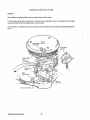
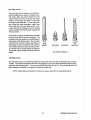
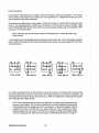
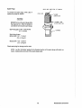
Replacing Filter Elements
Generator models covered by this manual have two
fuel filter screens. One is in the carburetor (this filter is referred to as the inlet filter screen).
To remove this filter screen, unscrew the filter plug
and remove the fuel filter screen behind the plug.
Clean the filter screen or replace it with a new one.
Periodically check this filter screen.
REMOVE PLUG
TO CLEAN
INLET
FUEL
SCREEN
39
A J -......
Westerbeke Generators
The engine-mounted electric lift pump contains
the second fuel filter screen. This pump supplies
fuel to the engine's carburetor during engine
operation. A cleanable filter screen is contained
in the pump's base.
Remove the base by placing a wrench on the hex
nut and twisting it loose from the bayonet fittings.
Clean the screen as needed. A new base gasket
must be installed each time the pump base is
removed and reinstalled. Make sure a good seal
exists when replacing the base cover.
Filter Screen
~~~::-t--Magnet
sealing Gasket
BOiseCo'ler
~WARNINGI
Shut off the fuel service valve althe engine when servicing the fuel system. Take care in catching any fuel thai may spill from within the pump when the base is removed. DO NOT allow
any smoking, open flames, or other sources of fire near the fuel system when servicing. Make
sure proper ventilation exists when servicing the fuel system.
Westerbeke Generators
40
ELECTRICAL SYSTEM
Engine 12·Voll DC Control Circuit
The engine that drives the generator end has a 12-Volt DC electrical control circuit, as shown on the wiring
diagrams which follow on pages 44 and 45. Refer to these diagrams when troubleshooting or servicing
electrical components on the engine.
CAUTION
To avoid damage to the battery's charging circuit, never shut off the engine's battery switch
while the engine is running.
However, shut off the engine's battery switch to avoid electrical shorts when working on the
engine's electrical circuit with the engine stopped.
An overspeed shutdown switch shuts off the generator set
should the engine's speed reach approximately 2175 rpm.
This shutdown circuit consumes 25 milliamps (.25 or 114th of
an Amp) at all times once the generator is connected to tts
battery. As this only amounts to about 18 Amp-hours in a
month, it is unnecessary to be concerned with this slight discharge during normal seasonal operation. If the generator set
were to be unattended for many months, the two easiest ways
to stop this slight drain is to first turn off the main battery switch
providing 12 volts to the generator set. The second way to
stop this slight drain is to remove the ignition fuse on the generator-mounted control panel.
B RMP
IGNITION
FUSE
Should the generator shutdown from an overs peed condition,
the overspeed circuit must be reset in order to restart the generator. If the overspeed switch itself is faulty and resetting it
by depressing the STOP switch will not reset it, lift the T-1 coil
connection from the overspeed switch and tape the terminal
end with electrical tape. DO NOT operate the generator with the overspeed swttch bypassed. Bypass the
overspeed switch only for testing purposes. Replace the overspeed switch to maintain this safety circuit's
integrtty.
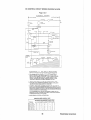
Battery Specification
The minimum recommended capacity of the battery used in the engine's 12-Volt DC control circuit is 90 125 Ampere-Hours (minimum) for the generator sets covered by this manual.
CAUTION
When quick-charging the battery with an external charger, be sure to disconnect the battery
cables from the battery. Leaving the charging circuit connected while quick-charging will
damage the diodes in the integral controller'S circuitry.
41
Westerbeke Generators
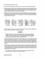
Testing the Batlery Charging CirclIil
1. AC Stator Winding,' O. 14 Ohms
Lift the two AC leads off the bridge rectifier and measure with an ohmmeter the resistance between these
two leads should measure 0.14 Ohm. No continuity should exist between these two leads and the ground.
2. Bridge Rectifier
Normal AC voltage running to the rectifier (while the engine is operating at 1800 rpm) is measured across
the two AC connections on the bridge rectifier. (See the illustration below.)
AC voltage running to the bridge rectifier (approximate):
No-load off the generator
16.0 Volts AC
Full-load off the generator
17.5 Volts AC
DC
+
I.e.
BRIDGE
RECTifIER
INTEGRAL
CONTROLLER
Normal DC voltage running out of the rectifier (in Volts DC) is measured across the two DC connections
of the bridge rectifier; that is, + and - .
DC voltage running from the bridge rectifier (approximate):
No-load off the generator
17.0 Volts DC
Full-load off the generator
18.5 Volts DC
3. Testing the Bridge Rectifier
A. Set your Ohmmeter's scale on RX1 ( + DC) and
set the needle to zero.
POlnl ~2
POint #1
POint #5
(Rectifier Mounting Hole)
B. Connect the (+) positive lead from the
Ohmmeter to point #4. Taking the Ohmmeter's
negative (-) lead, momentarily touch points #1,
#2, #3, and #5. The Ohmmeter should register
no deflection for any of the points touched.
C. Remove the positive (+) lead from point #4
and connect the negative (-) lead to point #4.
Touch points #1, #2, and #3. The needle
should deflect, indicating a passage of current
Westerbeke Generators
42
through the diodes located internally at these points.
D. With the (-) negative lead still connected to point #4, touch point #5. The needle should not deflect.
E. Place the (+) positive lead on point #1 and the (-) negative lead on point #3. The Ohmmeter again
should not register any deflection (no deflection indicated infinite resistance). Reverse these connections and the Ohmmeter should again register no deflection. IF THE RECTIFIER FAILS ANY OF THE
PREVIOUS TESTS (A - E), REPLACE THE RECTIFIER BECAUSE IT IS DEFECTIVE.
4. Integral Controller (I.C.)
The integral controller (I.C.) is an encapsulated, solid-state unit that supplies a DC charging voltage to the
generator's starting battery while the generator is operating.
Charging Voltage:
Charging Amperage:
13.0 - 14.0 Volts DC
0-10AmpsDC
A separate group of stator windings supplies AC voltage to a bridge rectifier which converts the AC current
into DC current to supply the I.C. unit. The I.C. unit senses the needs of the starting battery and supplies a
DC charge when one is needed. If you suspect that the I.C. unit is faulty (that is, if the battery's charge is
low), check the charging circuit's components and performance by following steps #1 - 3. Check all connections for cleanliness and tightness including the ground before replacing the I.C. unit.
NOTE: When the generator is first started, the I.C. unit will produce a low charging rate. This
charging rate will rise as the generator is operated for awhile.
White/ Yellow
(+1 Plus
Terminal 01 Recti/ior
While IGreen
(-) Negative
Terminal 01 Rectifier
White I Black
Ground V
While/Red
O.C.Charge
NOTE
*
white/Green (-) Negative
and White/Black Ground
are interchangeable.
43
Westerbeke Generators
DC CONTROL CIRCUIT WIRING DIAGRAM #35439
Page 1 of 2
L - - 4:0KV,--:-BC =--COIL CONNECTIONS
6,~KW
J
Be - THRLJ 6186
.0.P.5HIDH\
:rtJlf
J 1C]ln
',,,
[XHAUS T TEMP.
SWITCH
I
rt
OUT PL'-
ro'e
GOlD
"v!>
B.
1
L1IJ~z!n
l
POWER
ALTERNATOR
rGROMMET
INTO PANEL
't~
OVfR~PE£D
~m
!;~-T Uly
CNAR('ER
I
lJ-++-t--t--+--t-l--4---r-
Ie-- - - - - - - ---'f---
0_1" SWITCH
"~
~c./wl", .. r't{
I
$TRIPC
1
I
~i-
1
1
1
't~
0
I
-~
,==1
.." .
~
~
".....
,~
i
"
"~ "0;;' r'·"u:~"
'''~ON
L.____________________".""~."""'!Wc'."'"._"'"••"'".'C____________t------I
'". YEclw!flH
$'">'''
PANEL
Westerbeke Generators
44
DC CONTROL CIRCUIT WIRING DIAGRAM #35439
Page 2 of 2
SCHEMATIC
'+
12VDC
BATTHW RETURN
~u
SHRT(R
J.
"Ut~N"TOR
~I
c ,,--1
,
,
I
~~NGIN<
~
.. r .1.01.
C~U(;ER
f.OOUNTEO
~;E~
1TOl'
I
STAn
I
" . ".. P
~r'(
"'~.T.~ ..
W,T.~".
OP'~""
,1
~
I,
~F"'£LLIF"''''''''P
+
a"LL"~T
DIODE
~
,$'0"'
"
"
__ ----1
OPTiON
0,
-
-
"
~u :I.~T
I
~"" ...",o.
.l.o~-l
START[!\
"OU ..... ETER
vOLn.oETER
M"
';£R
""
.J'
LJ
O.P.
~E"OER
/.
RE!ol5TOR
-
,
OvER~PEtO
I--
Co<o.(
,-,-""uRETOR so\.
,--1:'.-.
1
I PANEL
e
Q.0'"
r .., '."
I
I ~O""P
1
DIAGRAM
BATTERY
;l' Y 9
-
I
--
--
RESPONSIBILITY
I
ShRT
RELeASE
( ) INDICATOR
COR SAFeTY REGULATIONS
;;T:'RT~R
1. THE MINIMUM VOLTAGE REQUIRED AT_n,!'
9 VOLTS. THEREFOR-~, W'RE (;AUGES FROU
,20LENQID 15
TBI-I TO Te~-,
"NO
SHOULD BE SELECTED TO GIVE A "'A~IMUM vorrAG'E
DROP or I VOLT OR !.-£55 THIS WILL pROVIDE'" vOLTS ,,:r THE
STARTER SOLENOID WHEN BATTERl TERMINAL VOLTAGE IS OOWN
TO 10 VOLT;', INDICATIVE Of A DEEPLY Q.1,!,Ct-1.o.RGED ElATTERY.
TBI-Z TO T!D-Z
2.
BIITTERY CHARGEI'< CIIU5[S A 9md ORIIIN AND OVERSPtED MODULE CAUSES
~
IS,.,d DRAIN WHEN
OPERATlN~.
GUIERATOR IS NOT
TlH;RUOR[, WifE" lEAVING
BOAT fOR AN . . TENDED "tRIDD, DI5eONN EeT TI1( aATTER~
~.
~ASOLIN£
"tSTERSEKE
GENERATORS AS
MARINE
~HIPP[D
FROM
TH£ FACTORY
~CLUSIVE ~, OPTIONAL REI~OT( 'NSTRUMfNT OR CONTROL PAN ELS ~OMPL! "IT"
~~O
\.1.5. COA~T
~UA.RO ;~UR·'d3.;l.eCES50RY I~SrRU~H'T
CO .... RL~ ANO AR. INTENDED TO
at
AND CONTROL PANelS DO NOT NECESSARILY SC
1~5TAlLED ASOVE OECK ANP"ISOI AT£D fROM !;A50LI~t
5OURCES·'IN ACCORDANCE WITH J3CFR·IS3.410(~).
IT IS THE RESPONSISILITY Of
eor
tNSHLLATION
OR CONTROL
T'1( BOH '-IA.N\.IFACTURER TO INSUR£
THES~ G~N~RATOR5 A,",O OPTIONALLY
P~NElS
THH T>I,
THUll RE'\OT~ 'NSTRl"1(NT
CO"'PLY WITH 33 CFR-IS3.
4 SENOERS SUPP\.I£O WIT" OPTIONAL INSTRUMENT PANEL.
MINIMUM WIRE GAUGES
(AWG)
litRE LfNGTH FRO'" (7EM[R.o.TOR TO R(MOn: ""-M{L
I
0-16· 1(;-20' 20-Z!>' 2~-:2' 32-40' 40-~0· ,>~:f,5'1
TERMINAL:;
Te,-z
° 12
'10
TO T6~-Z I
I"
,2
I
10
I:~
14
14
"
"
",.
14
Tel-, TO T(>4-1 I : !
;:~~ ~oo :::=~
TBZ-4 TO Ta
.rnz~
'~"7
;
TEll-I TO TB3-'
TO
4.~
T~_5
I
,4
14
14
I
I -10
IZ
I·
45
'oJ
I
10
10
<J
~
I
9
I~
I'"
I~
I
14
,"
1<1
'<1
,4
1-4
1
14
Westerbeke Generators
OPTIONAL REMOTE START PANEL WIRING DIAGRAM # 35706
OPTIONRl REMOTE START PANEL (REAR VIEW} PART' 33183
r-- - - - - - - - - - - - - - ------,
I
I
116 RED
112 YHLOIi/W/REO
STRIPE
I
I
I
I
C~
~
..
Alf;~
~t'-112RtO
~ w f~'~~~
",
,
7TART
."
"
~
I
~-
SIR IfE
I
I
I
I
I
1,:3-1
"~I
."
T4~f
PURPLE
14- 2
14-3
·· 6>6>
· L--~4_5
0
~
14-4
L--
I
MODEL I OWG HUMBER
I
6>6>
I
L
I
I
I
r--
I
I
I
I
.
~,
YELLOW/Ii/HO
I
[
~
ID-
112 REO/Ii/PURPLE SlRll'E
I ,"
I ,
I ~
I
l
[-
.ill!
I "
I
n
r-
I
BeG 4.0KW 11S43!1
BeG 6.5KW 135439
I
I
I
." RED/ii/PURPLE
9 liMP STARTING
TO 12-1
B16 9. ilKWI 36397
TO TBl-2
6 AMP RUHHING
I
I
114 PURPlE
2 AMP
I
I
I
I
I
I
I
114 BLACK
2 AMP
TO 12-5
TO 18)-5
_ _ _ _ _ _ _ _ _ _ _ ---1I
C--'-
112 YELLOW/lURED STRIPE
12 AMP SHIRTING
19 AIoIP STARTING
112 REO/Ii/PURPLE STRIPE
G AMP RUNNING
Weslerbeke Generators
46
TO 18]-]
1- - - -
I
I
I
I
r:-
:!:l
TOT2-2
L--
STOP
iZREO/W!PUR
19AMP STAR
6 AMP RUN
#
14PURPLt
2AMP
I
TO T82-1
START
TOT2_3~#14LTOlUE
TO T2A
T4-1
11'-14 TAN
I,
TO T2 5---------+
I
(REAR VIEW)
-- -
ASS"f PN 3~, 102
------- -
------ - -
14 BLACK
ZAMP
0
z
f!
H
4turbo
I Lf~~fp~~< I
ON
STRIPE
.... 12HL/W nlOSTRIPE
::0
m
OIL
I 8 T42&4V
.(-16 PURPL E
Plnssuln
0:\
\i~
--
~16 PURPL E
"16 BL ACK
/
I
-'----'----1--+---'
!Il.
~
til
~
TO HI3-j
o
"""
n
6T4-48
14-5
IS
I
"
"
u
"~
;1
1I
v
~H;TAN
13·]
~
8
1.3-2
"'16 BLACK
HOURS
VOL T5
~Ib
1
T -II
l'3AMP STARTING
TO TI.Z----1'12YEUW/RED
12AMP STARTINC;
.
I
~
T4
:'12 puR/wiRED
STRIPE
T
w
'16BLACK
I
TO T81-1
L~
,
~
"16LT-BLUE
I e -Ei
6 Ar-.1P
;:
-HATER TEMP.
I
~
-----,
~
"'Hi puRrLE
1
TOT83-5
-
JOI2RED!W!PURPLt:
STRIPE
~12RED/w/pUR SH<IPt.
II
TC Ttol2·2
-- -
:::!
o
L&
j
:
-
!/le RFli
~
I
TO T63-2
-
"'12YEL/w/RED STRIPE
I
!
TO T2-1----1
INSTHUf\lENT PANEL
,,'
I
TO T81-2
REMOTE
--- -
-'-/-
I
G.5K.W 8C
.
:SEE D'vIG, 3~'-:Y:)
--- -
~K~
I
4KW BC
-
REO/W/PURPLt STRIPE
I
I
9K\1 8T
SEE 0\1(,.30397
--- -
RUNNING
STRIPE,
Cl
til
:l
~
M II\iLiI,'Llllld
1l'lB.s.
$28 UG E::'O
WIHE LENGTH FROM GENERATOR TO PANEL(Fn
WIRE
GAUGE
(AWG)
I
I
I
I
I
I
1
1
1
I
I
I
1
I
I
I
I
1~~I~:r~25f~~2r~t~:t ;O~6S
0
n1
Z
(I)
-!
::0
c:
;:
m
Z
-!
:
Z
m
r-
:e
:i:i
Z
c
Cl
I
I
g
1
I
»
;:
I
...
I
I
I
I
,_ .-J
I
L __ _
o
iil
PURPLE
1
1
::0
=Ij,
'"
:::l
'"
COOLING SYSTEM
Description
Westerbeke marine gasoline engines are designed and equipped for fresh water cooling. Heat produced in
the engine by combustion and friction is transferred to the fresh water which circulates throughout the engine. This circulating fresh water cools the engine block and tts internal moving parts. The heat is transferred
externally from the fresh water to sea water by means of a heat exchanger, similar in function to an automotive radiator. Sea water flows through the tubes of the heat exchanger While fresh water flows around the
tubes; engine heat transferred to fresh water is conducted through the tube walls to the sea water which is
pumped into the exhaust system and discharged overboard. In basic terms, the engine is cooled by fresh
water, the fresh water is cooled by sea water, and the sea water carries the transferred heat over the side
through the exhaust system. The fresh water and sea water circuits are independent of each other. Using
only fresh water within the engine allows the cooling water passages to stay clean and free from harmful
deposits. The two independent circuits and their components are discussed in the following paragraphs.
Fresh Water Circuit
NOTE: Refer to paragraphs A and B in this section on the recommended antifreeze and water
mixture to be used as the fresh water coolant, and for information on filling the fresh water
system.
Fresh water Is pumped through the engine by a belt-driven circulating pump, absorbing heat from the engine. The fresh water coolant circulates through the engine's block absorbing heat, then passes through
the thermostat into the exhaust manifold, then to the heat exchanger where tt is cooled, and then is returned
to the engine block through the suction side of the fresh water circulating pump. When the engine is started
cold, external fresh water flow is prevented by the closed thermostat (although some fresh water flow is
bypassed around the thermostat to prevent the exhaust manifold from overheating). As the engine warms
up, the thermostat gradually opens, allowing the engine's fresh water coolant to flow unrestricted to the external portion of the cooling system.
A. Fresh Water Coolant (Antifreeze) Mixture.
A freshwater and antifreeze mixture should be used year-round. Water, when tt freezes, expands sufficiently to split the heat exchanger and crack the engine block. A water/antifreeze mixture of proper concentration will prevent freezing (see page 49 for an antifreeze/water mixture chart).
Use soft water with few impurtties, such as tap water (potable water) or rainwater. Never use hard or foul
water. Use of hard water or water containing impurities will lead to the collection of scale in the engine and
heat exchanger which will reduce the cooling system's efficiency.
Antifreeze of poor quality or without rust inhibitors will cause corrosion within the COOling system. Always
use antifreeze which is compatible with aluminum cooling system components and which is made by a reliable manufacturer. Never mix different brands of antifreeze.
Make sure that the cooling system of the engine is well cleaned before adding antifreeze.
Recommended antifreeze for year round use is ZEREX or PRESTONE with rust inhibitors.
In order to control the concentration of the mixture, mix the antifreeze and fresh waterthoroughly before adding it to the cooling system.
Westerbeke Generators
48
ANTIFREEZE CONCENTRATION DATA
Antifreeze
Concentration
Freezing
Temperature
%
13
23
,F
(' C)
23
(-5)
14
(-10)
30
35
5
-4
(-15) (-20)
45
50
-22
-40
(-30) (-40)
60
-58
(-58)
NOTE: An antifreeze concentration should be selected on the basis of a temperature which
is about 10' F (5' C) lower than the actual atmospheric temperature expected.
B. Filling the Fresh Water System
A coolant recovery tank kit is supplied with each Westerbeke gasoline generator. The purpose of this
recovery tank Is to allow for engine coolant expansion and contraction, during engine operation, without the
loss of coolant and without introducing air into the cooling system.
This coolant recovery tank should be installed at, or above, the engine's manifold level, in a location where
it can be easily monttored and where coolant can be easily added if needed (see the figure below). A stainless steel mounting bracket is supplied with each ktt along with a 30-inch length of clear plastic hose and
clamps to connectthe hose between the engine's manifold fitting to the hose spud on the base of the recovery
tank.
COOLANT RECOVERY TANK
\ '.; \t '.'-,I'
'. ' 'i'~ \ "r
,','
"
f
.,'
\
J.. ,,\.
,\ , \
,., ,/,
Coolant Recovery Tank, Recommended Installation
49
Westerbeke Generators
FUNCTION OF MANIFOLD PRESSURE CAP
From Coolant Tank
to Coolant Yank
COOLANT EXPANSION
Coolant from the engine, when heated during the engine's operation, will expand, lift the spring-loaded
manifold pressure cap, and enter the recovery tank via the hose connecting the recovery tank to the manifold.
When the engine is shut down and cools, a small check valve in the pressure cap is opened by the contraction of the engine's coolant, allowing some of the coolant in the recovery tank to be drawn back into the
engine's cooling system, free of air and without loss. Periodically check that the passage (Al between the
90· fitting on the manifold and the filler neck in the manHold is clear so coolant can flow in either direction.
Fill the fresh water system as follows:
1. Remove the pressure cap from the manifold.
2. Pour a clean, fresh water coolant mixture into the manHold and allow enough time for the coolant to fill
the fresh water cooling system and expel all air.
3. Replace the pressure cap on the manifold.
4. Remove the plastic cap from the coolant recovery tank and fill the tank with coolant halfway between the
ADD mark and the MAX mark. Replace the cap on the manifold.
5. Start and run the engine long enough for the engine to warm up so the thermostat will open, allowing the
coolant to flow through the engine block and to the rest of the fresh water cooling system.
6. Add coolant to the recovery tank, as required, to top off the fresh water cooling system.
Thermostat
Generally, thermostats are of two types. One is simply a choking device which opens and closes as the
engine's temperature rises and falls. The second type has a bypass mechanism. Usually this is a disc on
the bottom of the thermostat which moves downward to close off an internal bypass passage within the
head. Since 1980, each type of thermostat has a hole punched through it. The hole is a bypass to prevent
the exhaust manifold from overheating during the engine's warm-up. Replacement thermostats must have
this design characteristic.
Westerbeke Generators
50
Sea Waler Circuil
The sea water flow is created by a belt-driven,
positive displacement, neoprene impeller pump.
The pump draws sea water directly from the
ocean through the sea cock and sea water
strainer and passes the water to the heat
exchanger's sea water inlet. The sea water passes through the heat exchanger's tubes, from
which heat from the fresh water system is absorbed and then is discharged from the cooling
system overboard through the water-injected wet
exhaust system.
.
~
.. t
.
A zinc anode, or pencil, is located in the sea water
cooling circuit within the heat exchanger. The
purpose of the zinc anode is to sacrifice itself to
electrolysis action taking place in the sea water
cooling circun, thereby reducing the effects of
electrolysis on other components of the system.
The condition of the zinc anode should be checked monthly and the anode cleaned or replaced,
as required. Spare anodes should be carried on
board.
...
::
NEW
ANODE
••..
REPLACE
REPLACE
CLEAN
OR
REPLACE
Zinc Anode Condnions
Sea Water Pump
The sea water pump is a self-priming, belt.<Jriven rotary pump with a non-ferrous housing and a neoprene
impeller. The impeller has flexible vanes which wipe against a curved cam plate within the impeller housing,
producing the pumping action. On no account should this pump be run dry. There should always be a
spare impeller and impeller cover gasket on board (an impeller kn).
NOTE: Impeller failures resulting from a loss of sea water coolant are not warrantable failures.
51
Westerbeke Generators
Governor and Water Pump Bell Tension
iWARNINGI
Never attempt to adjust the drive belt's tension whOa the engine is in operation.
CAUTION
Excessive governor and water pump drive bell tension can cause rapid wear of the belt and
reduce the service life of the fresh water pump and governor shaft bearings. Excessive slack
or the presence of oil on the belt can cause belt slipping, resulting in high operating temperatures, as well as poor regulation during generator load changes.
The governor and water pump drive belt is property adjusted if the belt can be deflected no less than 3/8
inch and no more than 1/2 inch (10 mm, 12 mm) as the belt is depressed with the thumb at the midpoint between the two pulleys on the longest span of the belt. (See the figure below.) Spare drive belts should be
carried on board.
3/0· TO 112·
DHl[CTIDN
FRESH
WATER
PUMP
lOUR PUll
CRAUSHAFT
PULLEY
Governor and Water Pump Belt Tension
Westerbeke Generators
52
Illustrated below is a typical Westerbeke engine's cooling system. Both fresh water and sea water flow
through their independent cooling circutts. Please refer to the Parts List for individual part numbers and
descriptions for your generator's cooling system.
WATER INJECTED
ELBOW
WATER
COOLANT
RECOVERY
TANK
HERT
OVERHERT ALARM
•
IleOMI.' SEn VATER
Typical Cooling System
53
Westerbeke Generators
LUBRICATION SYSTEM
Engine Oil
For the engine's lubrication, use a lubricating oil designated for gasoline service. Use a good grade of oil
having an API specification of SO or SE, preferably SF. DO NOT use oils designated OS.
Engine Oil Viscosity (SAE Number)
Use oil having a viscosity best suited to the atmospheric temperature. Refer to the oil viscosity chart below.
TEMPERATURE
-30
c"
F"
-20
-20
o
-10
0
20
40
,':;~#'}~~'W$J!i:W,>i'J:·1 ~~~~'-~-<>
,~-
-~~1'~~-
10
20
60
30
80
40
50
100
120
.,*~~:-: '''''"_'_ '. :':''R'Th~~~~'~:''
44m#¥tlw*!2:o#i@>
ENGINE OIL
Oil Pressure
The engine's oil pressure is indicated by the oil pressure gauge (when equipped with one) or is monitored
by the standard oil pressure switch.
During normal operation, the engine's oil pressure will range between 35 and 55 psi (engine hot).
NOTE: A newly started, cold engine can have an oil pressure reading upwards of 60 to 60 psi.
A warmed engine can have an oil pressure reading as low as 35 psi. These readings may also
vary depending upon the load that is placed on the generator.
Your generator set is fitted with an oil pressure sensing switch as standard equipment. Should your engine's
oil pressure drop below a safe operating pressure, the sensor will shut the engine OFF to prevent any internal damage to your generator's engine from occurring by interrupting the DC voltage to the ignition coil.
Westerbeke Generators
54
Engine Oil Change (10 include filler)
1. Draining the Oil Sump
Discharge the old oil through the sump drain hose (attached at the front of the engine) while the engine is still
warm. Drain the old oil completely, replace the hose in
its bracket, and replace the end cap securely.
Always observe the old oil as it is removed. A yellow/gray
emulsion indicates the presence of water in the oil. Although this condition is rare, it does require prompt attention to prevent serious damage. Call a competent
mechanic should water be present in the oil. Sea water
present in the oil can be the result of a fault in the exhaust
system attached to the engine, and/or water siphoning
through the sea water cooling circuit into the exhaust,
filling it up into the engine (refer to the exhaust illustrations on pages 21 and 23).
I
\1\1\11'111
II! IlliI'III1T?" I
,
2. Replacement of the Oil Filter
When removing the used oil filter, you may find it helpful
and cleaner to punch a hole in the upper and lower portion of the old filter to drain the oil from it into a container
before removing it. This helps to lessen spillage. A small
style automotive filter wrench should be helpful in removing the old oil filter. Place some paper towels and a plastic bag around the filter when unscrewing it to catch any
oil left in the filter. (Oil or any other fluid on the engine
reduces the engine's cooling ability. Please keep your
generator's engine clean.) Inspect the old oil filter as it is
removed to make sure that the rubber sealing gasket
came off with the old oil filter. If this rubber sealing gasket remains sealed against the engine block, gently
remove it. The replaceable cartridge-type oil filter requires no cleaning inside, so IT may be properly disposed
of.
When installing the new oil filter element, wipe the filter
gasket's sealing surface on the engine block free of oil
and apply a thin coat of clean engine oil to the rubber gasket on the oil filter. Screw the filter onto the threaded oil filter stub, and then tighten the filter firmly by hand
NOTE: Generic filters are not recommended, as the material standards or diameters of important items on generic parts might be entirely different from genuine parts. Immediately
after an oil filter change and oil fill, run the engine to make sure the oil pressure is normal and
that there are no oil leaks around the new oil filter.
55
Westerbeke Generators
3. Filling the Oil Sump
Add fresh oil through the oil filler cap on the valve cover.
After refilling the oil, run the engine for a few moments
while checking the engine's oil pressure. Make sure
there is no leakage around the new oil filter or from the
oil drain system, and then stop the engine. Then check
the quantity of oil with the dipstick. Fill to, but not over,
the high mark on the dipstick, should the engine require
additional oil.
Oil Filler Cap
Rocker Cover
Oil Dipstick
Upper Li.it
(Nor.al leveli)
-"-'-t~::=:==:=:===1
Lower
Crankcase
Westerbeke Generators
56
Be GENERATOR
The Be generator is a brushless, self-excited generator which requires only the driving force of the engine
to produce an AC output. The stator houses two sets of windings: the main stator windings and the exciter
windings. When the generator is started, residual magnetism in the four rotating poles induces a current in
the stator exciter windings. This flow of current then induces a greater current flow through the four rotating poles which then generates an even larger current in the exciter windings. This mutual build up of current in the four rotating poles and in the exciter windings quickly reaches the saturation point of the
capacitor(s) and a regulated energy field is then maintained in the stator. At the same time, this regulated
field produces a steady voltage in the stator windings which can then be drawn off the generator's AC terminals to operate AC equipment.
r
,
D
a
-
-
- - - - - -
-
- -
-
-
-
-
-
--
-
-
-
-
- - - -
-
-
-
-
-
-
-
-
--
-
---,
I
I
I
I
,
I
DC
I
,r---------,
I
,
I
BRIDGE
I
I
I
1. C.
AC
,,I
INTEGRAL
I
RECTIFIER
CONTROLLER
_ _ _ _ , _ _ _ _ _ _ _ _ _ _ _ _ _ _ _ _ --lI
101
I
I
I
I
,
,
I
,
A
I
AC
,
------01
I
I
,I I'
'
I'
:I
R I
MI
------02,'
- ------03 N ,
------0. l i,I B
',0 lODE
,
,, ,,
,,
I
i
,
:
INTEGRAL
L '
CONTROLLER
------05·'
EARLIER MODELS
~.~~=-====~?~:-.J
o•
1
o
5
II.. _________ .J,
2
o
c
t:iPHj:t
I
~C?J
L ___________ J
Be S.SKW and 6.0KW
o
3
o
6
o
AC TERMINAL BLOCK
!
'--------- ---_._-'
DC
I. C.
oC 'I
I I
HZ
CHARGE
A
I ,
I
I
'-'0....... _60
.
II
,
BALLAST RESISTOR
[ I
,
,I
I
T I
!
Be 4.0KW and 4.4KW
Generator Internal Wiring Schematic with
DC Battery Charging Circuit
A. Rotating Field/Auxiliary
B. Integral Controller with Ballast Resistor
(Earlier Models)
Windings wtth Diodes
C. Exciter Windings and Capacitor(s)
D. Bridge Rectifier and Integral Controller
Generator Frequency
Frequency isa direct result of engine/generator speed: 1800 RPM - 60 Hertz, 1500 RPM -50 Hertz To change
the generator's frequency, refer to the "MAINTENANCE AND ADJUSTMENTS" section of this manual, page
70.
57
Westerbeke Generators
No-load Voltage Adjustment: BGG 4.0KW
1. Remove the louvered metal plate covering the terminal connections and the capacitor (see page 59).
2. Start the generator and allow it to run for approximately five minutes so the engine can warm up. Make
sure the generator is operating without any equipment drawing AG current from the generator (that is,
shut OFF all electrical appliances). Make sure the engine's speed (Hertz) is correct. Adjust the governor
as needed to obtain the correct engine speed before proceeding.
3. Referring to the AG load connections diagram below, check the generator's no-load voltage by measuring the voltage across the neutral lead and the hot lead with a volt meter. Make sure you record this reading. The generator's no-load voltage is 115 - 124 volts at 60.5 - 61.5 Hertz. If the voltage output is higher
or lower than specified, proceed.
l,
N
4 3
5_ a2 6
1
4_3
5
2a6
N
1
N
l2
4
5_2_
t
L,
110v 50 Hz
120v 60Hz
3
6
L,
220v 50 Hz
L,
l2
1 4
3-
1 4-=-3
6_
5a2-6
,N
240v 60Hz
N
220v 50Hz
4. Shut off the generator. Make sure the correct Hertz lead (60 Hertz #6, or 50 Hertz #5) is plugged into the
capacitor. Refer to the illustration on the top of the next page.
JWARNING!
DO NOT attempt to make a no-load voltage adjustment while the generator is operating. The
capacitor can hold a 450 - 500 volt charge. Touching any wiring can result in a severe electrical shock. In addition, attempting to make a no-load voltage adjustment while the generator
is operating can cause fingers to be caught in the generator's rotor.
5. Refer to the illustrations the next page before making any adjustments. Note that there are three plugs
grouped for the right capacitor terminal, #7, #8, and #9. If the generator's no-load voltage is low, then
disconnect the lower numbered plug and connect the plug with the next higher number. If the generator's
no-load voltage is high, then disconnect the higher numbered plug and connect the plug with the next
lower number. Note that the plug presently connected to this terminal may be anyone of the three plugs
available.
6. If the generator's no-load voltage cannot be adjusted because the voltage needs to be increased and the
highest numbered plug is already connected to the right terminal, or the voltage needs to be lowered and
the lowest numbered plug is connected, then follow the steps at the bottom of the next page. Ask your
local Westerbeke dealer for a Be GENERAL TROUBLESHOOTING GUIDE before performing the steps
listed at the bottom of the next page.
NOTE: Make sure the insulating covers on the unused leads are in place and are not In contact with each other or in contact with the generator's housing.
Westerbeke Generators
58
THE 11 PLUG IS
SHOWN CONNECTED
TO THE CAPACITOR
ONLY FOR DEMONSTRATION PURPOSES.
<:>
C
YO
'"
BeG 4.0KW GENERATOR
AC load Connection
Ter.inal Block
Generator End
(over Plate
H.
,
Capacitor ::::,~--tF;III-
'"
No-load Uoltage
Adjustment Plugs
50 Hertz Plug
CAUTION:
DO
NOT
ALLOW ANY OF THESE
PLUGS TO TOUCH THE
GENERATOR"S HOUSING.
WINDINGS WXLL BURN
IF THESE PLUGS TOUCH
THE HOUSING OR OTHER
W1RES.
A. Check the resistance of the exciter windings
B. Check the capacitor.
BCG 4.0KW: 31.5 uF ± 5'
BCG 4.0KW : 1.9 Ohms
C. Check the engine's speed.
60 Hertz: 60.5·61.5
50 Hertz: 50.5· 51.5
Adjust the engine's speed by use of the governor speed adjustment, page 74, to obtain the correct Hertz.
NOTE: Refer to the "NOTE" at the bottom of page 62.
59
Weslerbeke Generators
No-Load Voltage Adjustment: BeG 6.5KW
1. Remove the louvered metal plate covering the terminal connections and the capacitor (see page 61).
2. Start the generator and allow tt to run for approximately five minutes so the engine can warm up. Make
sure the generator is operating without any equipment drawing AC current from the generator (that is,
shut OFF all electrical appliances). Make sure the engine's speed (Hertz) is correct. Adjust the governor
as needed to obtain the correct engine speed before proceeding.
3. Referring to the AC load connections diagram below, check the generator's no-load voltage by measuring the voltage across the neutral lead and the hot lead with a volt meter. Make sure you record this reading. The generator's no-load voltage is 115 - 124 volts at 60.5 - 61.5 Hertz. If the voltage output is higher
or lower than specified, proceed.
l,
N
4 3
5. .2 6
1
N
1
5
N
L2
I.,
1 4
3
5e2e
6
I 4 3e
5 2 68
1 4e::::s3
5e2e6
l,
l. N
L2
483
2.S
l,
110v 50 Hz
120v SO Hz
220v 50Hz
240v SO Hz
4. Shut off the generator. Make sure the correct Hertz lead (60 Hertz #6, or 50 Hertz #5) is plugged into the
capacitor. Refer to the illustration on the top of the next page.
~WARNINGI
DO NOT attempt to make a no-load voltage adjustment while the generator is operating. The
capacitor can hold a 450 volt charge. Touching any wiring can result in a severe electrical
shock. In addition, attempting to make a no-load voltage adjustment while the generator is
operating can cause fingers to be caught in the generator's rotor.
5. Refer to the illustrations on the next page before making any adjustments. Note that there are three plugs
grouped for the right capacitor terminal, #7, #8, and #9. If the generator's no-load voltage is low, then
disconnect the lower numbered plug and connect the plug with the next higher number. If the generator's
no-load voltage is high, then disconnect the higher numbered plug and connect the plug with the next
lower number. Note that the plug presently connected to this terminal may be anyone of the three plugs
available.
6. If the generator's no-load voltage cannot be adjusted because the voltage needs to be increased and the
highest numbered plug is already connected to the right terminal, or the voltage needs to be lowered and
the lowest numbered plug is connected, then follow the steps listed at the bottom of the next page. Ask
your local Westerbeke dealer for a BC GENERAL TROUBLESHOOTING GUIDE before performing the
steps listed at the bottom 01 the next page.
NOTE: Make sure the insulating covers on the unused leads are in place and are not in contact with each other or in contact with the generator's housing.
Westerbeke Generators
so
"'•"
THE 17 PLUG IS
SHOWN CONNECTED
TO THE CAPACITOR
ONLY FOR DEMONSTRATION PURPOSES.
w
-'
...
N
~
~
::
'"
'"
e
"'
BCG 6.SKW GENERATOR
AC Load Connection
Ter.inal Block
Capacitor
Adjustment
Plugs
DO NOT ALLOW
THESE PLUGS TO TOUCH
THE GEHERATOR"S HOUSING.
WINDINS WILL BURN IF
PLUGS TOUCH HOUSING OR
OTHER WIRES.
CAUTION:
58 Hertz
Plug
B. Check the capacitor.
A. Check the resistance of the exciter windings
BCG 6.5KW: 31.5 uF ± 5"
BCG 6.5KW : 1.9 Ohms
C. Check the engine's speed.
60 Hertz: 60.5 - 61.5
50 Hertz: 50.5 - 51.5
Adjust the engine's speed by use of the governor speed adjustment, page 74, to obtain the correct Hertz.
NOTE: Refer to the "NOTE" at the bottom of page 62.
61
Westerbeke Generators
Load Connections
The generator's data plate gives the voltage, current and frequency rating of the generator. An AC wiring
decal is affixed to the inside of the louvered cover on the generator end. A diagram of the various AC voltage connections is provided on the decal.
The generator is a single-phase, reconnectable 120 Volts AC two-wire or 120/240 Volts AC three-wire, at 60
Hertz; or 110 Volts AC two-wire, 110/220 Volts AC three-wire, or 220 Volts AC two-wire, at 50 Hertz. Refer
to the "SYSTEM SPECIFICATIONS" section of this manual for generator ratings, page 13 for the BCG 4.0KW,
and page 17 for the BCG 6.5KW.
NOTE: The frame ground wire must be moved when changing from 110 Volts, 50 Hertz to /220
Volts, 50 Hertz.
A circuit breaker should be installed between the generator and the AC load. This circuit breaker should be
rated at 120% of the generator's AC output and be able to react quickly to overloads, subject to motor starting considerations.
l
L1
N
N
N
1b
1
483
I 4CJ 3
1 4 34111
t 4e:::::::lD3
5
206
5-2-
6
5,2 6.
54111286
Ltl N
N
220v 50Hz
4 3
5. 82 6
L,
110... 50Hz
120... 60 Hz
2
Lj
220... 50 Hz
240\160 Hz
For making connections to the AC terminal block, use terminal ends for #10 studs which will accept multistrand wire sized for the number of conductors in the bundle, the rating of the conductor's insulation, and
amperage that will be drawn through the conductor(s). (Refer to the generator's data plate for the generator's amperage and voltage ratings.)
NOTE: When changing Hertz produced by the generator, an engine speed adjustment at the
governor must be made. The AC output connections on the above illustrated terminal blocks
must be selected for the voltage and Hertz to be produced. A plug at the capacitor must be
changed for 50 (#5) or 60 (#6) Hertz use. Early models with 3 wire connections to the integral controller require a 50 (#5) or 60 (#6) Hertz connection change at the bridge rectifier
in the DC charging circuit. Refer to the "Generator's Internal Wiring Schematic" on page 57.
Weslerbeke Generators
62
Shore Power Connections
If the installer connects shore power to the vessel's AC circuit, this must be done by means of the SHORE
POWER/OFF/SHIPS GEN., center position-off transier switch shown below. Use of this switch prevents
simultaneous connection of shore power to generator output.
CAUTION
Damage to the generator can result if utility shore power and generator output are connected
at the same time. This type of generator damage is not covered under the warranty; it is the
installer's responsibility to make sure all AC connections are correct.
Generator
HOTE: !lIAGRIlM SHOWS CONNECTIONS FOR IIiOWIRE. 12f1-VOLT SYSTEM. fOR THREE-WIRE
SYSTEM USE DOll EO LINES fOR THE
DTllfR HOT LEGS.
~
t
1
=
L -_ _ _----,
I
,/--....
L-----,HD
~~,_
r-----\a>
tID
---,
I
""I
!
,I
,,I
I
L-+'------~"~-'1'~\--~, I
SHIP-IO-SHORE SWITCH
1
II
, __ ",,/I
(3
,,--> -'~-~:]s,,,p,
~
r;
I"
'-
/
LOAD
' ' 0-''_' ' ' ' __...;...______-11 ,.
POLO
PH 3268H
149 AMPS/POLU
PH 32089
(8i1 AHPS/POLfl
PM 32e18
(125 AMPS/PDL£)
PH 32133
(289 M-IPS/POlE 1
~
ShOfe PCNJilf
NOTE, OIAGRAM SHOWS CONNECTIONS fOR A IWOWIRE, 120-VOLT SYSTEM fROM THE GENERATOR,
WITH THREE-WIRE, I20-VOlT
L -________---"B"'O"'AT'-iS YS TE M.
Generator
rN
GI'~
-
Ship-to-Shore Switch (3 Pole)
PH
329BB
(48
AMPS/POLE)
PH
321HI9
(BI'!
PH
AMPG/POLE;)
32918
(.l:n,
AMPS/POLE)
PH 32133
(209
AMPS/POLl::)
Shore Power Switch Connection Diagrams
63
Westerbeke Generators
GENERAL INFORMATION AND CARE OF THE GENERATOR
Use of Electric Motors
The power required to start an electric motor is considerably more than is required to keep n running after
n is started. Some motors require much more current to start than others. Split-phase (AC) motors require
more current to start, under similar circumstances, than other types. These motors are commonly used on
easy-starting loads, such as washing machines, or where loads are applied after the motor is started, such
as small power tools. Because they require 5 to 7 times as much current to start as to run, their use should
be avoided, whenever possible, if the electric motor is to be driven by a small generator. Capacitor and
repulsion-induction motors require from 2 to 4 times as much current to start as to run. The current required
to start any motor varies with the load connected to n. An electric motor connected to an air compressor,
for example, will require more current than a motor to which no load is connected.
In general, the current required to start 115-Volt motors connected to medium starting loads will be approximately as follows:
MOTOR
SIZE
(HP)
AMPS FOR
RUNNING
(Amperes)
1/6
1/4
1/3
1/2
3/4
1
3.2
4.6
5.2
7.2
10.2
13
AMPS FOR
STARTING
(Amperes)
6.4 to 22.4*
9.2 to 32.2*
10.4 to 72.8*
14.4 to 29.2
20.4 to 40.8
26 to 52
* Note that in the above table the maximum "Amps for Starting" is more for some small motors
than for larger ones. The reason for this is that the hardest starting types (spin-phase) are not
made in larger sizes.
Because the heavy surge of current needed for starting motors is required for only an instant, the generator
will not be damaged if n can bring the motor up to speed in a few seconds. If difficulty is experienced in
starting motors, turn off all other electrical loads and, if possible, reduce the load on the electric motor.
Required Operating Speed
Although individual units may vary slightly, the normal voltage and frequency of typical 6O-(50-)Hertz enginedriven generators described in this manual are shown on the chart on the next page.
Run the generator at first with no load applied, then at half the generator's capacITy, and finally loaded to its
full capacity as indicated on the generator's data plate.
See the rpm/Hertz/frequency chart on the next page.
Westerbeke Generators
64
4-Pole
Speed
(rpm)
Frequency
(Hertz)
Generator
120V (110)
Plants
Voltage
240V (220)
Plants
None
1830
(1530)
62
(52)
122
(112)
240
(224)
Half
1800
(1500)
60
(50)
120
(110)
240
(220)
1755
(1455)
59
(49)
110
(100)
220
(200)
Load
Applied
Full
The output voltage should be checked periodically to ensure proper operation of the generating plant and
the appliances tt supplies.
If an AC voltmeter or ampmeter is not installed to monitor voltage and load, check tt wtth a portable meter
and amp-probe.
Preventive Maintenance (Generator)
Maintenance on the generator is minimal.
1. Keep the generator clean, dry and well-ventilated.
2. Make sure all connections are clean and tight and that cables carrying AC voltage are properly supported
and protected against chafing.
3. The rear armature bearing is lubricated and sealed; therefore, no maintenance is required. If the bearing
becomes rough or noisy, replace it.
Generator Troubleshooting
A complete and illustrated text on troubleshooting the BC series of generators is furnished in the Technical
Manual which is available through your local dealer.
65
Westerbeke Generators
ENGINE TROUBLESHOOTING
Introduction
The tables which follow indicate troubleshooting procedures based upon certain problem indicators, the
probable causes of the problems, and the recommendations to overcome these problems.
Note that the engine's control system (electrical system) is protected by a 20-Ampere manual reset circuit
breaker located next to the starter motor and the (-) ground terminal. Refer to the model photographs at the
beginning of this manual for a photograph showing the exact position of this reset circuit breaker.
Possible Cause
Trouble
1. Out of fuel.
Engine cranks but fails
to start.
2. Engine is flooded.
3. Filters are clogged by contaminated fuel.
4. Voltage drop at ( + ) at overspeed switch.
5. Worn or faulty spark plugs.
6. Bad ignition coil.
7. High-tension leads grounding (wet system).
8. Automatic Shutdown switch is faulty.
9. Fuel pump inoperative because filter is
clogged.
10. Filter in carburetor is clogged.
11. Tripped overspeed switch (reset and start).
Engine does not crank.
1. Battery is low or dead.
2. Engine's DC 20-Amp breaker has tripped.
3. Sea water filled cylinders.
4. Loose battery connections.
5. Voltage drop at starter solenoid terminal.
6. Bad starter solenoid.
7. Faulty START switch.
Westerbeke Generators
66
Possible Cause
Trouble
1. Faulty automatic shutdown switch
(oil, water, or eXhaust).
Engine starts, runs and then
shuts down.
2. Faulty overspeed switch (reset and start;
bypass SWITch to test).
3. Faulty fuel pump.
4. Faulty STOP switch.
5. Engine circutt breaker is tripping.
6. Dirty fuel filters.
7. Low oil level in sump.
8. Mechanical check valve at the fuel supply
fuel pump is unable to draw fuel through this valve.
Back firing through carburetor.
1. Ignition timing is wrong.
2. Engine is flooded.
3. Choke is stuck closed.
4. Spark plug wires are connected wrong -check firing order.
5. Distributor cap is cracked.
6. Dirty air cleaner.
Engine overheats.
1. Coolant loss (pressure test the cooling system).
2. Belts are loose or broken.
3. Sea water pump's impeller is faulty.
4. Sea water pump is worn.
5. Faulty hose.
6. Thermostat is stuck closed.
7. Heat exchanger is clogged.
8. Faulty gauge (check with a thermometer).
67
Westerbeke Generators
Possible Cause
Trouble
1. Throttle linkage is binding.
Engine hunts.
2. Dirty fuel filters.
3. Defective fuel pump.
4. Governor is out of adjustment.
5. Valves are out of adjustment.
6. Generator is overloaded.
7. Cracked distributor.
8. Faulty high-tension leads.
1. Ignition timing is wrong.
Engine misfires.
2. Spark plugs are worn.
3. Valve clearances are incorrect.
4. Dirty carburetor.
5. Dirty air cleaner.
6. Poor quality fuel.
1. Faulty gauge.
High oil pressure.
2. Relief valve is stuck.
3. Dirty oil or wrong SAE type oil is in the engine.
1. Low oil level.
Low oil pressure.
2. Faulty gauge.
3. Wrong SAE type oil is in the engine.
4. Relief valve is stuck.
5. Faulty oil pump.
Westerbeke Generators
68
Possible Calise
Trouble
No DC charge to the
starting battery.
1. Connections to the alternator are loose or
faulty.
2. Faulty alternator.
3. No eXCITation to the regulator's yellow
lead.
Black exhaust smoke Is discharged
from the engine.
1. Dirty air intake.
2. Choke is stuck closed.
3. Carburetor is flooding.
Blue exhaust smoke is discharged
from the exhaust.
1. Valves are worn or adjusted incorrectly.
2. Piston rings are worn or unseated.
3. Lubrication oil is diluted.
4. Crankcase breather hose is clogged.
69
Westerbeke Generators
MAINTENANCE AND ADJUSTMENTS
Introduction
This section contains a scheduled preventive maintenance program and several adjustment procedures the
owner/operator can perform without the benefit of sophisticated and expensive tools and instruments.
Preventive Maintenance (Engine)
Perform the preventive maintenance in accordance with the schedules listed in the following paragraphs.
Adherence to these schedules will make sure the equipment is maintained in the best possible condition and
that it will perform to expectations. Those items marked by an asterisk (") are recommended to be performed by an authorized dealer or distributor.
Daily (before each use)
1. Check the oil sump level. Maintain the oil level at or near the upper level mark on dipstick.
2. Check the coolant level in the plastic recovery tank. Maintain the coolant level halfway between the
MAX and ADD marks.
3. Visually inspect the unit; check for loose belts, chafed or broken wires, loose brackets and fittings,
damaged hoses, loose clamps, and other equipment not properly secured.
4. Check the fuel supply. Fill the tank(s) with a good grade of unleaded or leaded gasoline that has an
octane rating of 89 or higher.
5. Check the primary filter/water separator. Drain and service this filter as required. (A primary filter/water
separator is optional, but strongly recommended. See page 39.)
6. If an optional instrument panel is installed, check the engine's gauges for proper oil pressure, operating temperature, and starting battery charging voltage once the engine is operating.
7. If AC gauges are installed, check the generator's output meters for proper AC voltage and output frequency.
Monthly
Check the condition of the zinc anode in the heat exchanger's sea water circuit. Clean or replace the anode,
as required. Keep the area inside the heat exchanger clean of zinc anode debris.
Servicing After Initial 50 Hours 01 Operation
1. Change the engine's lubrication oil and oil filter.
2. Clean or replace the fuel filter screen in the carburetor and in the electric fuel lift pump.
3. Retorque the cylinder head bolts.
Weslerbeke Generators
70
4. Adjust valve clearances.
5. Adjust the alternator and water pump drive belt tension, if required.
6. Adjust the engine's no-load speed, IT required (Hertz). Please note that this adjustment is not a warrantable adjustment during or after the unit's break-in.
Servicing After Every 100 Hours of Operation
1. Change the engine's lubrication oil and oil filter.
2. Adjust the alternator and water pump drive belt tension, IT required.
Servicing After Every 250 Hours of Operation
Clean or replace the fuel filter element in the carburetor and in the electric fuel lift pump.
Servicing After Every 500 Hours of Operation
*1. Adjust the valve clearances.
3. Drain, flush, and refill the fresh water cooling system
*4. Check the condition of the starter motor drive pinion; lubricate pinion.
5. Check the outside of the engine. Make sure any oil on the engine's surface is cleaned. Any dirt or oil
on the engine inhibits the engine's ability to cool. Please keep the engine clean.
6. Check the sea water pump for internal wear. Examine the pump's cover, cam, and internal housing.
Replace worn parts as needed. Check for leaks and repair them as needed.
Servicing After Every 800 Hours of Operation
*1. Check the battery-charging alternator for proper operation.
*2. Check the tightness of bolts, nuts, and clamps.
Servicing After Every i 000 Hours of Operation
1. Remove, clean, and pressure test the primary heat exchanger. (A local automotive radiator shop should
be able to clean and test the heat exchanger.)
NOTE: Operating in silty and/or tropical waters may require that a heat exchanger cleaning
be performed more often than every 1000 hours.
71
Westerbeke Generators
Preventive Maintenance (Generator)
Maintenance on the generator end is minimal:
1. Keep the generator clean, dry, and well-ventilated.
2. Ensure that all connections are clean and tight, and that cables carrying AC voltage are properly supported and protected against chafing.
*3. The rear armature bearing is lubricated and sealed; no maintenance is required. However, Hthe bearing becomes noisy or rough-sounding, have it replaced.
Generator Frequency Adjustment
Frequency is a direct result of engine/generator speed, as indicated by the following:
When the generator is run at 1800 rpm, the AC voltage output frequency is 60 Hertz. When the generator is
run at 1500 rpm, the AC voltage output frequency is 50 Hertz.
Therefore, to change the generator's frequency, the generator's speed must be changed. To accomplish
the frequency change, connect the AC output leads to the AC terminal block in accordance wtth the "AC Voltage Connections" diagram specified for your generator set, which appears in the "BC GENERATOR" section of this manual, page 62.
Westerbeke Generators
72
Ignition Timing
1. Attach a timing light to the #1 spark plug and mark the front crankshaft pulley timing notch. Locate the
timing pointer on the front gear case ant mark it as well (use a piece of soap, white chock, or white crayon
when making this mark).
2. Start the engine and warm it up to its normal operating temperature. Make sure the generator is operating without a load on it.
3. Using the timing light, align the timing groove in the front crankshaft pulley with the timing pointer. Do this
by loosening and slowly rotating the distributor body. Refer to the timing specifications below.
BCG4.0KW
BCG6.5KW
Timing Specifications:
16' ± l' BTDC at 1800 rpm
14' ± l' BTDC at 1800 rpm
lIMING POINTER
/
TIMING
MAR K -\--~~~
THnNG
MARK
(1800 RPM)
BeG G. SKW
BeG 4.0KW
Electric Choke
The electric choke uses a 12-Volt heating element which opens the choke automatically once the engine
starts and remains running. Some hunting will be present when the generator is started, is on choke, and is
running without a load on the generator.
IWARNINGI
To avoid burns on fingers or hands, DO NOTtouch the choke
housing while the engine is operating. Allow the engine to
cool before making choke adjustments.
~
LEAN
Adjustthe choke by loosening the three cover-securing screws and
by rotating the cover clockwise to set the choke ENRICH and
counterclockwise to set the choke LEAN. The choke is initially set
at the factory.
73
Weslerbeke Generators
Governor Adjustments
Operate the generator set to bring the unit up to ITS operating temperature before attempting an adjustment.
NOTE: If the governor is severely out of adjustment, manually adjust the linkage without any
load on the generator to obtain a safe output voltage before proceeding with the adjustment.
Three adjusting points are on the governor. (Refer to the illustration below.)
BCG 6.5KW Governor
1. Bumper Screw This screw is used to
remove a no-load surge ONLY.
NEVER turn the bumper screw into the
governor far enough so that it increases
the no-load speed. To adjust the governor, turn the bumper screw in until the
engine stops surging. Now bring the
Increase/Decrease Speed Screw (on
the governor) up until the generator
runs between 60.5 to 61.5 cycles noload. Apply a 1/4, a 1/2 and a 3/4 load
to the generator and ensure the generator does not surge under these three
load intervals.
NOTE: Only If the generator surges
at any of these load intervals are
you to follow steps #2 and #3
below.
INCREASE/DECREASE SPEED SCREW
CARBURETOR THROTTLE LEVER
BCG 4.0KW Governor
2. Increase/Decrease Speed This adjusting bolt sets the no load speed of the
engine. (The linkage arm between the
governor arm and throttle lever should
be adjusted to hold the throttle full open
when the engine is not running.) Make
sure this linkage moves freely and that
the ball joint connectors are properly
lubricated. Use graphite lubricant at
this connection. Disconnect the ball
joint and apply a graphite lubricant to
the inside of the joint.
3. HuntinglBeculatjQo !f the variation in
engine speed between no load and full
load is too great, adjust this eye bolt to
draw the spring closer to the lever hub.
The increase/decrease speed boll may
need to be adjusted as well.
INCREASE/DECREASE
SPEED SCREW
LIIUA6E
ADJUSTMENT
CARBURETOR THROTTLE
IIDJUSHtEKf
If the governor surges while under a load, adjust this eye bolt to move the spring away from the lever hub.
(Check the speed adjustment.)
Westerbeke Generators
74
Governor Maintenance
1. Periodically lubricate the attaching points at both ends of the governor arm. Use a graphite lubricant or
an equivalent.
NOTE: Free movement of this linkage arm is important for proper governor/throttle operation.
2. Governor oil capac~y: BCG 4.0KW is 1.5 ounces of SAE #10/30 motor oil.
BCG 6.5KW is 3.0 ounces of SAE #10/30 motor oil.
NOTE: Do not overfill the governor.
3. Change the governor's oil every 1000 hours of operation.
4. The drive belt should be maintained in good condition. Replace the belt if it becomes worn or shows signs
of cracking.
To change the oil, remove the governor from engine and remove the oil fill and fill level plug and drain all the
oil from the governor. Reinstall the governor on the engine and fill it with the proper quantity of SAE 10/30
engine oil, and replace the plugs.
75
Westerbeke Generators
Carburetor Adjustment
1. Idle Mixture Jet
Disconnect the throttle linkage arm from the governor control arm and reduce the engine's speed with the
idle stop screw. Turn the idle mixture screw clockwise (In) until the engine skips; back the screw out
(counterclockwise) slowly until the engine smooths then skips again; then turn the screw clockwise (in) 1/4
to 1/2 of a turn. The idle mixture should be satisfactory at this setting.
2. Run Mixture Jet
This mixture jet is pre-sized at the factory and is not adjustable. An adjustment to the idle jet screw, while
the unit is operating at 1800 rpm, will have an affect on the unit's performance. Refer to the "Governor Adjustments" section of this manual for instructions on how to adjust the engine's speed, page 74.
SCREENED
AIR
(LEANER
THROTTlE
SlOP
~~~Yl~~~~~~~
FUEl
SOLENO D
IDLE MIXTURE JEI
Westerbeke Generators
76
Torquing Cylinder Head Bolts
Tighten the cylinder head bolts according to the sequence shown in the illustration below. Make sure the
engine is cold when this is done. Loosen one head bold one-half turn and then tighten It to the specified
torque. Then proceed to the next head bolt in the sequence numbering shown.
BeG 4.8KW TIGHTENING SEQUENCE
8(G Ii.SlW
TIGMTEKIKG SEQUENCE
Torque Specifications:
BCG 4.0KW
28.9 - 36.2 Ib-ft (4.0 - 5.0 kg-m)
BCG 6.5KW
36.2 - 43.4 Ib-ft (5.0 - 6.0 kg-m)
77
Westerbeke Generators
Valve Clearance Adjustment: BCG 4.0KW
NOTE: Retorque the cylinder head bolts
before adjusting the engine's valves.
ADJUST EXHAUST VALVES TO 0.008 INCHES
(0.20 14M)
ADJUST INTAKE VALVES TO 0.010 INCHES
(0.25 14M)
1. Remove the rocker cover and the gasket.
2. Rotate the crankshaft in the normal direction
of rotation and place the No. 1 piston at TDC
(Top Dead Center) on its compression stroke.
AdJustthe intake and exhaust valve clearances
for the No.1 cylinder. Make sure the valves for
this cylinder are closed when this adjustment
is performed.
3. Rotate the crankshaft 360'. The valves for
cylinder NO.2 should now be closed. Nowadjust the valves for cylinder No.2.
Adjust the intake valves to 0.008 inches (0.20
mm), and the exhaust valves to 0.010 inches (0.25 mm) with the engine cold.
4. Replace the rocker cover along with a new rocker cover gasket.
Rocker cover torque: 5.1 - 9.4 Ib·ft (0.7 - 1.3 kg-m)
Valve Clearance Adjustment: BCG 6.5KW
NOTE: Retorque the cylinder head bolts
before adjusting the engine's valves.
ADJUST EXHAUST VALVES TO 0.0071 INCHES
(0.18 14M)
ADJUST INTAKE VALVES TO 0.0071 INCHES
(0.18 14M)
1. Remove the rocker cover and the gasket.
2. Rotate the crankshaft in the normal direction of
rotation and place the No.1 piston atTDC (Top
Dead Center) on its compression stroke. Ad·
just the intake valve clearances for the No. 1
and No. 3 cylinders, and the exhaust valve
clearances for the No. 1 and No.2 cylinders.
Make sure these valves are closed when per·
forming this adjustment.
3. Rotate the crankshaft 360° and adjust the No.
2 cylinder's intake and the No.3 cylinder's exhaust valve clearances.
Adjust all valves to 0.0071 inches (0.18 mm) with
the engine cOld.
4. Replace the rocker cover along with a new rocker cover gasket.
Rocker cover torque: 5.8· 8.7Ib·ft (0.8·1.2 kg·m)
Westerbeke Generators
78
Spark Plugs
WEAR AND ADHESION OF CARBON
To service the spark plugs, clean, gap or
replace the plugs as needed.
PlUG GRP
BURNT
CONDITION
CAUTION
DRMRGE AND
DETERIORATION
DO NOT remove the spark plugs while
the engine is hot. Allow the engine to
cool before removing the spark plugs.
Spark plug gap: 0.028 - 0.036 inches
(0.7 - 0.9 mm)
DAMAGE
Spark plug torque:
BCG 4.0KW 13.1 - 17.4 Ib-ft
(1.8 - 2.4 kg-m)
BCG 6.5KW 10.8 - 15.9 Ib-ft
(1.5 - 2.2 kg-m)
Check each plug for damage and/or wear.
NOTE: Loc-tite "Anti-Seize" applied to the threaded portion of the spark plugs will retard corrosion, making future removal of the spark plugs easier.
79
Westerbeke Generators
LAY-UP AND RECOMMISSIONING
General
Many owners rely on their boatyards to prepare their craft, including engines and generators, for lay-up
during the off-season or for long periods of inactivity. Others prefer to accomplish lay-up preparation themselves.
The procedures which follow will allow you to perform your own lay-up and recommissioning, or to use as
a check list if others do the procedures. These procedures should afford your engine protection during a
lay-up and also help familiarize you with the maintenance needs of your engine.
If you have any questions regarding lay-up procedures, call your local servicing dealer; he will be more than
willing to provide assistance.
Fresh Water Cooling System
A 50-50 solution of antifreeze and fresh water is recommended for use in the fresh water cooling system at
all times. This solution may require a higher concentration of antifreeze, depending on the area's winter
climate. Check the solution to make sure the antifreeze protection is adequate.
Should more antifreeze be needed, drain an appropriate amount from the engine block and add a more
concentrated mixture. Operate the engine to ensure a complete circulation and mixture of the antifreeze
concentration throughout the cooling system. Now recheck the antifreeze solution's strength.
Lubrication System
With the engine warm, drain all the lubricating oil from the oil sump. Remove and replace the oil filter. (Place
some paper towels and a plastic bag around the filter to catch the oil during its removaL)
When installing the new oil filter, be sure to apply a small amount of oil on the rubber sealing gasket at the
base of the filter. Fill the sump with the correct amount of oil for your engine model. Use an oil with an API
specification of SD, SE or SF. Run the engine and check for proper oil pressure and make sure there are
no leaks.
CAUTION
DO NOT leave the engine's old lubricating oil in the sump over the lay-up period. Lubricating oil and combustion deposits combine to produce harmful chemicals which can reduce
the life of your engine's internal parts.
Fuel System
Top off your fuel tanks with regular or unleaded gasoline with an octane rating of 89 or higher. Fuel additives should be added at this time to control algae and condition the fuel. Care should be taken that the additives used are compatible with the primary filter/water separator used in the system. Change the element
in your primary fuel filter/water separator, if the fuel system contains one, and clean the separator sediment
bowl. Clean the filter screen in the fuel lift pump and in the carburetor.
Westerbeke Generators
80
Sea Water Circuit
Close the through-hull sea cock. Remove the sea water intake hose from the sea cock. Place the end of
this hose into a 5-gallon bucket of clean fresh water. Before starting the engine, check the zinc anode found
in the primary heat exchanger on the engine and clean or replace it as required. Clean the sea strainer, if
one is installed in the inside of the hull.
Start the engine and allow the sea water pump to draw fresh water through the system. When the bucket
is empty, stop the engine and refill the bucket with an antifreeze solution slightly stronger than needed for
winter freeze protection in your area.
Start the engine and allow all of this mixture to be drawn through the sea water system. Once the bucket is
empty, stop the engine. This antifreeze mixture should protect the sea water circuit from freezing during the
winter lay-up, as well as providing corrosion protection.
Remove the impeller from your sea water pump (some antifreeze mixture will accompany IT, so catch it in a
bucket). Examine the impeller. Acquire a replacement, if needed, and a cover gasket. Do not replace the
impeller (into the pump) until recommissioning, but replace the cover and gasket. See the "Cylinder Lubrication" section below.
Intake Manifold and Through-Hull Exhaust
Place a clean cloth, lightly soaked in lubricating oil, around the air arrester. Be sure to remove this cloth
before recommissioning. Make a note to remove the cloth prior to start-up. The through-hull exhaust port
can be blocked in the same manner.
Starter Motor
Lubrication and cleaning of the starter drive pinion is advisable, if access to the starter permits its easy
removal. Make sure the battery connections are shut off before attempting to remove the starter. Take care
in properly replacing any electrical connections removed from the starter.
Cylinder Lubrication
Fogging the engine should be done as the last of the antifreeze mixture is drawn into the sea water circuit.
Remove the air intake screen (the air filter) and spray Marvel Mystery Oil or another commercially available
fogging oil into the carburetor while the engine is running. Spray enough oil to stall the engine. This will
coat the walls of the cylinders, pistons, and valve surfaces with this protective oil. Remove the spark plugs
and spray a small amount of this oil into each spark plug hole and turn the engine over two or three complete revolutions by hand. Reinstall, but do not tighten, the spark plugs, as these will need to be cleaned
and gapped prior to recommissioning. Close off the carburetor's air filter with an oily rag.
Spares
Lay-up time provides a good opportunity to inspect the equipment to see if external items such as drive belts
or coolant hoses need replacement. Check your basic spares kit and order ITems not on hand, or replace
those ITems used during the lay-up, such as filters and zinc anodes. Refer to the "SPARE PARTS" section
of this manual, page 83.
81
Westerbeke Generators
Batteries
If batteries are to be left on board during the lay-up period, make sure they are fully charged, and will remain
that way, to prevent them from freezing. If there exists any doubt that the batteries will not remain fully
charged, or that they will be subjected to severe environmental conditions, remove the batteries and store
them in a warmer, more compatible environment.
Recommissioning
The recommissioning of your Westerbeke unit after a seasonal lay-up generally follows the same procedures as those presented in the "PREPARATIONS FOR STARTING" section, page 33, regarding preparation
for starting and normal starts. However, some of the lay-up procedures will need to be counteracted before
starting the engine.
1. Remove the oil-soaked cloths from the intake manifold and from the through-hull exhaust port.
2. Remove the sea water pump cover and gasket. Discard the gasket. Install the sea water pump impeller
removed during lay-up (or a replacement, if required). Install the sea water pump cover with a new cover
gasket.
Wear rubber gloves, a rubber apron, and eye protection when servicing batteries.
Lead acid batteries emit hydrogen, a highly-explosive gas, which can be ignited by electrical
arcing or a lighted cigarette, cigar, or pipe. Do not smoke or allow an open flame near the
battery being serviced. Shut off all electrical equipment in the vicinity to prevent electrical arcing during servicing.
3. Reinstall the batteries that were removed during the lay-up, and reconnect the battery cables, making
sure the terminals are clean and that the connections are tight. Check to make sure the batteries are fullycharged.
4. Check the condition of the zinc anode in the sea water circuit and clean or replace the anode as needed.
Note that it is not necessary to flush the antifreeze/fresh water solution from the sea water coolant system. When the unIT is put into operation, the system will self-flush in a short period of time WITh no adverse affects.
5. Start the unIT in accordance with those procedures found in the "STARTING PROCEDURES" section of
this manual, page 34.
Westerbeke Generators
82
SPARE PARTS LIST
Since a possibility exists in which the engine may need to be serviced at sea or while in a port other than
your home port, certain spare parts should be kept on board to help minimize delays in your voyage. Please
refer to your engine's Parts List for part numbers when ordering spare parts.
Listed below are those spare parts that should be carried on board at all times.
1. An Impeller Kit
2. An Electric Fuel Lift Pump Filter and a Secondary Fuel Filter.
3. One Sea Water Pump Belt and One Fresh water Pump Belt
4. Hose Clamps
5. A Spare Oil Filter with a Spare Quart of Engine Oil and a Gallon of Premixed Antifreeze
6. Spark Plugs, Ignition Wires, and a Distributor Cap
7. Fuses
Other parts, whose life expectancy cannot be accurately predetermined, should be carried on board (in addition to those listed above) especially if the vessel is to be taken on long ocean voyages. These parts are
listed below.
1. Cooling System Hoses
5. A Starter
6. A 20 Amp DC Circuit Breaker
7. An Electric Fuel Lift Pump
8. A Sea Water Pump
9. Battery Terminal Connectors
The spare parts listed directly above are those we recommend be carried on board during long ocean
voyages. You may wish to ask other boat owners who have similar crafts and who have completed long
ocean voyages as to what spare parts they carried on board and what parts were needed at specific times
of the voyage. From the list provided directly above and from these inquiries, you can determine what spare
parts may be needed. In addition, if you are planning a long ocean voyage, consult your local Westerbeke
dealer for a listing of the Westerbeke dealers located on your route.
83
Westerbeke Generators
TABLE OF STANDARD HARDWARE TIGHTENING TORQUES
Unless stated otherwise for a specific assembly, use the following torque values when tightening standard
hardware,
Pitch
Ib-ft
kg-m
Grade <II
6mm bolt
8mm bolt
10mm bolt
10mm bolt
12mm bolt
12mm bolt
12mm bolt
13mm bolt
14mm bolt
14mm bolt
16mm bolt
16mm bolt
head/nut
head/nut
head/nut
head/nut
head/nut
head/nut
head/nut
head/nut
head/nut
head/nut
head/nut
head/nut
1
1,25
1.25
1.5
1,25 (ISO)
1,5
1,75
1,5
1.5
2
1,5
2
2,9 - 5,1
7,2 - 11,6
13,7 - 22.4
13,0- 21,7
25,3 - 39,8
25,3 - 39,8
21,7 - 36,2
32,5 - 50,6
36,2 - 57,9
34,0 - 55,7
54,2 - 79,6
51.4 - 76,7
0.4 - 0,7
1.0 - 1,6
1,9 - 3,1
1,8 - 3,0
3,5 - 5,5
3,5 - 5,5
3,0 - 5,0
4,5 - 7,0
5,0 - 8,0
4,7 - 7,7
7,5 -11,0
7,1 -10,6
head/nut
head/nut
head/nut
head/nut
head/nut
head/nut
head/nut
1
1.25
1,25
1.5
1.25 (ISO)
1.5
1,75
4,3 10,8 21.7 19,5 36,2 36,2 34,7 -
0,6 1.5 3,0 2,7 5,0 5,0 4,8 -
Grade 61
6mm bolt
8mm bolt
10mm bolt
10mm bolt
12mm bolt
12mm bolt
12mm bolt
6,5
15,9
32,5
30.4
57,9
50,6
49,2
0,9
2,2
4,5
4,2
8,0
7,0
6,8
Grade 7T flT and 8 8
6mm bolt head/nut
8mm bolt head/nut
10mm bolt head/nut
10mm bolt head/nut
12mm bolt head/nut
12mm bolt head/nut
12mm bolt head/nut
13mm bolt head/nut
14mm bolt head/nut
14mm bolt head/nut
16mm bolt head/nut
16mm bolt head/nut
1
1,25
1,25
1,5
1,25 (ISO)
1,5
1.75
1,5
1,5
2
1,5
2
5,8 - 8.7
14,5- 21,7
28,9 - 39,8
26,8 - 37,6
54,2 - 75,9
50,6 - 65,1
43.4 - 61.5
57,9 - 86,8
72,3 -108,5
68.7 -101,3
108.5 - 166.4
101,3 -159,1
0,8 - 1.2
2,0 - 3,0
4,0 - 5,5
3,7 - 5,2
7,5 -10,5
7,0 - 9,0
6,0 - 8,5
8,0 -12,0
10,0 -15,0
9,5 - 14,0
15,0 - 23,0
14,0 - 22,0
1/4 UNC
9 - 11
1/4 UNF
11c 13
5/16 UNC
5/16 UNF
3/8 UNC
3/8 UNF
7/16 UNC
7/16 UNF
1/2 UNC
1/2 UNF
18
21
28
30
44
50
68
73
1.2 - 1,5
1.5 - 1.8
2,5 - 2,8
2,9 - 3,2
3,7 - 4,6
4,1 - 4,8
6,1 - 6,8
6,9 - 7,6
9.4-10,1
10,1-11.1
Grade 5 QapsQrflW
Westerbeke Generators
84
-
20
23
33
35
49
55
73
80
TABLE OF TIGHTENING TORQUES
Cylinder head bolts*
BCG 4.0KW
BCG6.5KW
28.9 - 36.2
36.2 - 43.4
4.0 - 5.0
5.0 - 6.0
(*See the Torquing Cylinder Head Bolts section on page 77.)
Crankshaft pulley to crankshaft
BCG4.0KW
BCG6.5KW
36.2 - 43.4
65.2 - 72.4
5.0 - 6.0
9.0 - 10.0
Rocker cover to cylinder block
BCG4.0KW
BCG6.5KW
5.1 - 9.4
5.8 - 8.7
0.7 - 1.3
0.8 -1.2
13.1-17.4
10.8 -15.9
1.8 - 2.4
1.5 - 2.2
Timing belt cover to cylinder head
(All Models)
1.4 - 2.9
0.2 - 0.4
Timing belt cover to cylinder block
(All Models)
7.2 - 11.6
1.0-1.6
7.2-11.6
9.4 -13.0
1.0 - 1.6
3.0 - 4.5
Valve adjusting screws
(All Models)
9.4 -13.0
3.0 - 4.5
Oil pan drain plug
(All Models)
18.1-25.3
2.5 - 3.5
Spark plug to cylinder head
BCG4.0KW
BCG6.5KW
Timing belt tensioner to cylinder block
BCG4.0KW
BCG6.5KW
85
Westerbeke Generators
INDEX
A
Adjustment, Carburetor ...............................................................................................................................76
Adjustment, No-Load Voltage, BCG 4.0KW ...............................................................................................58
Adj ustment, No-Load Voltage, BCG 6.5KW ...............................................................................................60
Adjustment, Valve Clearance, BCG 4.0KW .................................................................................................78
Adj ustment, Valve Clearance, BCG 6.5KW .................................................................................................78
Adjustments, Governor................................................................................................................................74
ADJU STMENTS, MAl NTENANCE AND ......................................................................................................70
Anode Conditions, Zinc ...............................................................................................................................51
ANTI FREEZE CONCENTRATION DATA .....................................................................................................49
Automatic Shutdown (I nstallation Checks) ................................................................................................28
B
Back-Pressure, Exhaust (Installation Checks) ............................................................................................22
Batteries (Installation Checks) .....................................................................................................................29
Battery Charging Circutt, Testing the ..........................................................................................................42
Battery Specification ....................................................................................................................................41
BC GEN ERATOR .........................................................................................................................................57
Belt Tension .................................................................................................................................................52
Bolts, Torquing Cyl inder Head ....................................................................................................................77
Break-I n Precautions ...................................................................................................................................36
C
CAUTIONS
ENGINE SHIPPED WITHOUT OIL ......................................................................................... 18
LI FTING TH E GENERATOR .................................................................................................. 19
PROLONGED CRANKING INTERVALS ......................................................... ,...................... 23
EXHAUST ELBOW CLAMP TORQU E ................................................................................... 24
GAS OLIN E LEAKAG E .........................................................................................................., 26
HULL FITTINGS """"'"'' ................................................... """"""""""""""'" .................... , 28
OVERCHARG I NG CON DlTlONS .........................................................................................., 28
STARTING THE GENERATOR WITH AC LOADS OFF .......................................................... 34
PROLONG ED CRANKI NG INTERVALS """"""""""""""'''''''''' ........................................., 34
CHARGING CI RCUIT '"'' .................................................., ............................................, ....... 41
QUICK-CHARG ING TH E SATTERY ...................................................................................... 41
EXCESSIVE BELT TEtJSIOtJ ................................................................................................ 52
GENERATOR AND SHORE POWER CONNECTIONS .......................................................... 63
REMOVI NG SPARK PLUGS .................................................................................................. 79
LEAVING OLD OIL IN THE SUMP OVER THE LAY-UP PERIOD ........................................... 80
Carburetor Adjustment ................................................................................................................................76
CARBU RETOR AND FUEL SySTEM...........................................................................................................38
CARE OF THE GENERATOR, GENERAL INFORMATION AND ................................................................64
Charging Circuit, Testing the Battery ..........................................................................................................42
Westerbeke Generators
86
Choke, Electric ............................................................................................................................................ 73
Connecting Pressure Sensing Devices to Oil Galleries (Installation Checks) .......................................... 27
Connections, DC Electrical (Installation Checks) ...................................................................................... 28
Connections, Load ...................................................................................................................................... 62
Connections, Shore Power ......................................................................................................................... 63
CONTENTS, TABLE OF ................................................................................................................................ 3
CONTROL CIRCUIT WIRING DIAGRAM #37190, DC ................................................................... 44 and 45
CONTROL PANEL, DESCRIPTION OF ENGINE ....................................................................................... 31
Cooling System (Installation Checks) ........................................................................................................ 27
COOLING SySTEM ..................................................................................................................................... 48
Cylinder Head Bolts, Torquing ................................................................................................................... 77
D
DC CONTROL CIRCUIT WIRING DIAGRAM #37190 .................................................................... 44 and 45
DESCRIPTION OF ENGINE CONTROL PANEL ........................................................................................ 31
DISCLAIMER, IMPORTANT PRODUCT SOFTWARE .................................................................................. 1
Drain Hose, Oil (Installation Checks) ......................................................................................................... 27
E
Electric Choke ............................................................................................................................................. 73
Electrical Connections, DC (Installation Checks) ...................................................................................... 28
Electrical System (Installation Checks) ...................................................................................................... 28
Electric Motors, Use of ................................................................................................................................ 64
ELECTRICAL SySTEM .................................................................................................,.. ,.. ,.. ,.. """"""""",41
Elements, Replacing Filter, .. ,.. """" .. ", .. ,.. "", .. ,."", .. ,.. ,.. ,.. ,.. ,.. ,.. ,.. ,.. ,.. "." .. ,.. ,.. ,.. ", .. ,.. ,.. ,.. ,.. "".,., .. "."" .. ", 39
Engine 12-Volt DC Control Circuit .............................................................................................................. 41
ENGINE CONTROL PANEL, DESCRIPTION OF ....................................................................................... 31
Engine Oil ,.. ,.... "",., .. ,"", .. ,", .. ,.. ,.. ,"', .. ,., .. ,... ,.. ,.. ,.. ,.. ".,,., .. ,.. ,.. ,.. ,,', .. ,""", .. ,.. ,.. ,.. ,""""", .. ,", .. ,.. ,""""', .. ,'" 54
Engine Oil Change (to include filter) ..................................................................... ,.......... ,.. ,..................... , 55
Engine Oil Viscosity (SAE Number) .. ,.. ,", .. ,""", .. ,.. ,.. "., .. ,.. ,.. ,.. "., .. ,", .. ,.. ,.. ,.. ,' .. ,', .. ,.. ,.. ,.. ,.. ,.. ,""", .. "., .. ,'" 54
ENG I NE TROUBLESHOOTING", .. " .. ,.. ,."", .. ,.. "."", .. ,.. ,.. ,.. ,.. ,.. ,.. """, .. ,.. "., .. ,.. "., .. ,.. ,.. ,.. ,.. ,.. ,.,."., .. ,.. """, 66
Equipment, Inspection of", .. ,.. ,.. " .. "" .. "" .. ,.. ,.. ,... ,.. " .... "., .. ,.. "" .. "., .. ,.. "", .. "" .. ,.. ,.. ,., .. ,.. "."., .. ,., .. ,.. ,."."." 18
Exhaust Back-Pressure (I nstallation Checks)., .. "", .. ,.. ,.. "" .. ,.. ,.. ,.. """, .. "",."., .. ,.. ,.. ,.. "" .. ,.. ",., .. ,.. ,.. """,. 22
Exhaust Elbow I nstallation (I nstallation Checks) ......................................................................................, 24
Exhaust System (I nstallation Checks)", .. " .. ,.. "", .. ,.. ,.. ,.. ,.. "" .. ,.. "" .. ,.. ,.. "",.""""., .. ,.. "" .. ,.. ", .. ,."., .. ,.. ""., 21
Exhaust System Failures (I nstallation Checks)."""" .. """,."""""""." .. ,.. ,.. ,.. ,.. "., .. ", .. """".", .. ,.. ""., .. ,." 23
F
Failures, Exhaust System (I nstallation Checks), .. ,.. """, .. "" .. ,.. """"", .. ,.. "" .. "" .. """ .. """""""""""""", 23
Filter Elements, Replacing, .... " .. "." .. ,.. ,.. ,.. " .. ,.. ,.. ,.. " .. """ .. """" .. ,.. ,.. ,.. """, .. ,.. ,.. """ .. """"" .. """" .. "."." 39
FORWARD .. ,.. "" .... ,.. ,., .. ,.. ,.. ,.. ,.. " .. ,.. ,.. ,.. "", .. ,.. " .. ,.. ,.. ,.. ,""' .. "", .. ' .. ,.. " .. ,.. ,.. ,.. ,.. ,.. ,', .. ,.. ,.. ,.. ,.. ,', .. ,', .. ,.. ,.""",,2
Fresh Water Circuit., .... ,.. ,.. "" .. " .. "", .. ,.. ,.. " .. "" .. ,.. "., .. ,.. ,.. "" .. ,.. ,.. ,.. ,... ,.. ,.. ,.. ,.. ,.. ,.. ,., .. ,.. ,.. "., .. ,., .. ", .. ,.. """ 48
Frequency, Generator .... " .... " .. ,.. " .. ,.. "" .. " .. ,.. ,.. ,.. ,.. ,.. "., .. ,.. ,.. ,.. " .. ,.. ,.. "",."."", .. ", .. ,.. "" .. """" .. """", .. "., 57
Fuel Filter, Optional,., .. ,.. ,.. ,.. ,.. "", .. " .. ""." .. ,.. ,.. ,.. "" .. """"., .. ,.. " .. ,.. ,.. "", .. "" .. "" .. ", .. ,.. ,.. """"", .. ,.. ", .. "." 39
Fuel System (I nstallatlon Checks) " .. ,", .. ,.. ,.. ',.', .. ,.. ,.. ,.. ,", .. ,." .. ,.. ,.. ,,", .. ,.. ,.. ,""', .. ,.. ,"", .. ,", .. ,",.,', .. ,.. ,",., .. 25
FUEL SYSTEM, CARBURETOR AND"""", .. ,.. ,.. "" .. ,..... ,.. ,.. ,.. "."." .. ,.. """"","""" .. """ ... "".", .. ", .. """ .. ,38
87
Weslerbeke Generators
G
Gasoline .......................................................................................................................................................38
GENERAL.. .....................................................................................................................................................5
GENERAL INFORMATION AND CARE OF THE GENERATOR .................................................................64
GENERAL SPECIFICATIONS BCG 4.0KW .................................................................................................10
GENERAL SPECIFICATIONS BCG 6.5KW ................................................................................................. 14
Generator (AC Output) (Installation Checks) .............................................................................................29
GENERATOR, BC ........................................................................................................................................57
Generator Frequency ..................................................................................................................................57
Generator Mounting - Location (Installation Checks) ................................................................................20
Generator Troubleshooting .........................................................................................................................65
Governor Adjustments .................................................................................................................................74
Governor and Water Pump Belt Tension ....................................................................................................52
Governor Maintenance ................................................................................................................................75
Grounding (Installation Checks) .................................................................................................................28
H
HARDWARE TIGHTENING TORQUES, TABLE OF STANDARD ...............................................................84
Head Bolts, Torquing Cylinder ....................................................................................................................77
Hose, Oil Drain (Installation Checks) ..........................................................................................................27
Ignition Timing .............................................................................................................................................73
IMPORTANT PRODUCT SOFTWARE DISCLAIMER .................................................................................... 1
INDEX ...........................................................................................................................................................86
Inspection of Equipment .............................................................................................................................18
INSTALLATION CHECKS ............................................................................................................................18
Instrument, Remote, and Start Panels, Optional ........................................................................................32
Intake System, Sea Water (Installation Checks) .........................................................................................27
L
LAY-UP AND RECOMMiSSiONING ............................................................................................................80
Lifting and Rigging (Installation Checks) ....................................................................................................19
Load Connections ........................................................................................................................................62
Location, Generator Mounting (Installation Checks) .................................................................................20
LUBRICATION SYSTEM ..............................................................................................................................54
M
MAINTENANCE AND ADJUSTMENTS .......................................................................................................70
Maintenance, Governor ...............................................................................................................................75
Maintenance, Preventive (Engine) ..............................................................................................................70
Maintenance, Preventive (Generator) .........................................................................................................65
Motors, Use of Electric ................................................................................................................................64
Westerbeke Generators
88
Mounting - Location, Generator (Installation Checks) ............................................................................... 20
N
No-Load Voltage Adjustment: BCG 4.0KW................................................................................................ 58
No-Load Voltage Adjustment: BCG 6.5KW................................................................................................ 60
o
Oil Change (to include filter), Engine ......................................................................................................... 55
Oil Drain Hose (Installation Checks) .......................................................................................................... 27
Oil, Engine ................................................................................................................................................... 54
Oil Galleries, Connecting pressure Sensing Devices to (Installation Checks) ......................................... 27
011 Pressure ................................................................................................................................................. 54
Oil Viscosity (SAE Number), Engine .......................................................................................................... 54
Operating Speed, Required ........................................................................................................................ 64
Optional Fuel Filter ...................................................................................................................................... 39
Optional Remote Instrument and Remote Start Panels ............................................................................ 32
Ordering Parts ............................................................................................................................................... 5
Overspeed Shutdown ................................................................................................................................. 35
p
PANEL, DESCRIPTION OF ENGINE CONTROL ....................................................................................... 31
PARTS LIST, SPARE ................................................................................................................................... 83
Parts, Ordering .............................................................................................................................................. 5
Power Connections, Shore ......................................................................................................................... 63
Precautions, Break-In .................................................................................................................................. 36
PREPARATION FOR STARTING ................................................................................................................ 33
Pressure, Exhaust, Back (Installation Checks) .......................................................................................... 22
Pressure, Oil ................................................................................................................................................ 54
Preventive Maintenance (Engine) ............................................................................................................... 70
Preventive Maintenance (Generator) ......................................................................................................... 65
Procedure, Remote Starting ....................................................................................................................... 35
Procedure, Remote Stopping ..................................................................................................................... 35
PROCEDURE, STARTING ........................................................................................................................... 34
PROCEDURE, STOPPiNG .......................................................................................................................... 36
PRODUCT SOFTWARE DISCLAIMER, IMPORTANT .................................................................................. 1
Pump, Sea Water ........................................................................................................................................ 51
Fi
Rigging, Lifting and (Installation Checks) .................................................................................................. 19
Remote Instrument and Start Panels, Optional ......................................................................................... 32
REMOTE INSTRUMENT PANEL WIRING DIAGRAM #35698 ................................................................... 47
REMOTE START PANEL WIRING DIAGRAM #35706 ............................................................................... 46
Remote Starting Procedure ........................................................................................................................ 35
Remote Stopping Procedure ...................................................................................................................... 35
89
Westerbeke Generators
Replacing Filter Elements ............................................................................................................................39
Requires Operating Speed ..........................................................................................................................64
S
Sea Water Circun .........................................................................................................................................51
Sea Water Intake System (Installation Checks) ..........................................................................................27
Sea Water Pump ..........................................................................................................................................51
Shore Power Connections ..........................................................................................................................63
Shutdown, Automatic (Installation Checks) ...............................................................................................28
Shutdown, Overspeed .................................................................................................................................35
SOFTWARE DISCLAIMER, PRODUCT SOFTWARE ....................................................................................1
SPARE PARTS LIST .....................................................................................................................................83
Spark Plugs ..................................................................................................................................................79
Start Panels, Optional Remote Instrument and ..........................................................................................32
STARTING, PREPARATION FOR ................................................................................................................33
STARTING PROCEDURE ............................................................................................................................34
Starting Procedure, Remote ........................................................................................................................35
Starting Under Cold Conditions ..................................................................................................................37
Starting Under Normal Conditions ..............................................................................................................36
STOPPING PROCEDURE ...........................................................................................................................36
Stopping Procedure, Remote ......................................................................................................................35
SYSTEM SPECIFICATIONS BCG 4.0KW....................................................................................................11
SYSTEM SPECIFICATIONS BCG 6.5KW....................................................................................................15
T
TABLE OF CONTENTS ..................................................................................................................................3
TABLE OF STANDARD HARDWARE TIGHTENING TORQUES ................................................................84
TABLE OF TIGHTENING TORQUES ..........................................................................................................85
Thermostat.. .................................................................................................................................................50
Timing, Ignition ............................................................................................................................................73
Torquing Cylinder Head Bolts .....................................................................................................................77
TROUBLESHOOTING, ENGINE .................................................................................................................66
Troubleshooting, Generator ........................................................................................................................65
u
Understanding the Gasoline Engine-Driven Generator................................................................................5
Use of Electric Motors .................................................................................................................................64
v
Valve Clearance Adjustment: BCG 4.0KW..................................................................................................78
Valve Clearance Adjustment: BCG 6.5KW..................................................................................................78
Ventilation (Installation Checks) ..................................................................................................................30
Viscosity, (SAE Number), Engine Oil ..........................................................................................................54
Voltage Adjustment, No-Load, BCG 4.0KW ...............................................................................................58
Westerbeke Generators
90
Voltage Adjustment, No-Load, BCG 6.5KW ............................................................................................... 60
W
iWARNINGsl
CARBON MONOXIDE GAS ................................................................................................... 21
SMOKING NEAR BATIERIES ............................................................................................... 29
SERVICING BATIERIES ....................................................................................................... 29
INSTALLING OPTIONAL REMOTE PANELS ......................................................................... 32
CARBON MONOXIDE GAS ................................................................................................... 34
OVERSPEED SHUTDOWM .................................................................................................... 35
SERVICING FUEL SySTEM ................................................................................................... 40
ADJUSTING BELT TENSiON ................................................................................................. 52
MAKING A NO-LOAD VOLTAGE ADJUSTMENT ................................................................... 58
MAKING A NO-LOAD VOLTAGE ADJUSTMENT ................................................................... 60
SERVICING ELECTRIC CHOKE ............................................................................................ 73
SERVICING BATIERIES ....................................................................................................... 82
WATER PUMP BELT TENSION .................................................................................................................. 52
WIRING DIAGRAM #37190, DC CONTROL CiRCUiT ...................................................................44 and 45
WIRING DIAGRAM #35706, OPTIONAL REMOTE START PANEL .......................................................... 46
WIRING DIAGRAM #35698, OPTIONAL REMOTE INSTRUMENT PANEL .............................................. 47
z
Zinc Anode Conditions ............................................................................................................................... 51
91
Westerbeke Generators
YOUR NOTES
Westerbeke Generators
92