1
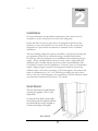
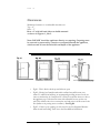
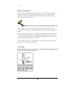
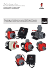
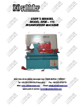
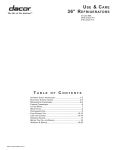
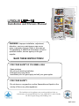
UNIQUE UGP-10
Installation and Owners Manual
WARNING: Improper installation, adjustment,
alteration, service or maintenance can cause
injury or property damage. Refer to this manual.
For assistance or additional information consult a
qualified installer, service agency or the gas
supplier.
!SAVE THESE INSTRUCTIONS!
FOR YOUR SAFETY IF YOU SMELL GAS
Open windows.
Do not touch electrical switches.
Extinguish any open flame
Immediately turn off gas supply and call your gas supplier
FOR YOUR SAFETY
Do not store or use gasoline or other flammable and liquids in the
vicinity of this or any other appliance
The installation of the appliance must conform with local codes or,
in the absence of local national Fuel Gas Code, ANSI Z233.1 and in Canada
B149.2 Propane Storage and Handling Code
2007-12-11
NOTICE TO INSTALLER/CUSTOMER
Please read carefully before hook-up!
1.
The dwelling must have an adequate air supply and access to fresh air/oxygen in order to operate safely. Propane fridges/freezers,
like any other gas appliance, must have access to fresh air/oxygen. This unvented appliance must not be used in an airtight application.
2.
This refrigerator must be installed by a licensed gas fitter.
3.
The propane gas supply pressure regulator must be set at 11” water column.
4.
The left side heat shield (facing front of the refrigerator) must be installed. The heat shield is shipped in the refrigerator carton.
5.
For safety & efficient operation the proper clearances on all sides and top must be maintained. The clearances are listed in the
Owner’s Manual.
6.
For proper and efficient operation the refrigerator must be level, both side to side and front to back (use bubble type level).
7.
The Combination Carbon Monoxide (CO) Alarm & Safety Shut-Off must be installed and connected (CM Models only) with the Alarm
mounted as indicated in the Carbon Monoxide Alarm (Monitor) Installation Manual.
NOTE: It is illegal to operate this refrigerator in Canada without the Combination Carbon Monoxide Alarm & Safety
Shut-Off installed, and will void the Canadian Standards Association Certification. Non compliance will void the
Canadian certification and void household/cottage insurance coverage. This refrigerator vents combustion products
directly into the living space. The CO Alarming Device with Safety Shut-Off has been added to this refrigerator to guard against
potentially high levels of Carbon Monoxide, which can kill you. Once unsafe levels of CO are detected, an alarm will sound and the
refrigerator will be shut off.
WARNING: Actuation of this device indicates the presence of unsafe levels of carbon monoxide (CO) which can KILL YOU. If
alarm signal sounds:
a.
Immediately move to fresh air --- outdoors or by an open door or window. Check that all persons are accounted for. Do not
re-enter the premises or move away from the open door/window until the emergency services responders have arrived, the
premises have been aired out, and your alarm remains in its normal condition;
b.
Call emergency local service telephone number, fire department or 911.
c.
The following symptoms may be related to CARBON MONOXIDE POISONING and should be discussed with ALL members of the
household:
Mild Exposure: Headaches, running nose, sore eyes, often described as “flu”-like symptoms;
Medium Exposure: Dizziness, drowsiness, vomiting;
Extreme Exposure: Unconscious, brain damage, death.
d.
Read the Instructions for complete Information on Alarms Signals.
8.
NOTE: The Combination Carbon Monoxide Alarm & Safety Shut-Off Instructions (CM Model), battery, Owners/Installation Manual
are stored inside the refrigerator.
For Unique Gas Products Support, Call Toll Free 1-877-427-2266
9.
Regular maintenance of the fridge is critical to prevent unsafe levels of Carbon Monoxide. Before lighting the refrigerator at any
time, clean the flue tube as per the Owner’s Manual & make sure the burner and areas around the burner are free from any lint,
spider webs or any other debris. Please record your appliance maintenance on the SERVICE RECORD label located at the back of
your appliance.
WARNING -- Test the Combination Carbon Monoxide & Safety Shut-Off device operation after the refrigerator has been in storage,
before each start up , and at least once per week during use.
The installation of the refrigerator must conform to the Local Codes. In the absence of a local code:
USA:
Canada:
Nation Fuel Gas Code
CSA B149.1 Natural Gas & Propane Installation Code
CSA B149.2 Propane Storage and Handling Code
CERTIFIED AND DISTRIBUTED BY
Unique Gas Products Ltd
““PPeerrssoonnaall SSeerrvviiccee &
& KKnnoow
maakkeess uuss U
wlleeddggee m
Unniiqquuee””
2245 Wyecroft Road #5
Oakville, Ontario Canada L6L 5L7
Ph: 905-827-6154 Toll Free: 1-877-427-2266 Fax: 905-827-2027
www.PropaneFridge.com
E-mail: [email protected]
Table of Contents
Chapters
Welcome
1
Safety and Warnings
1
Appliances and Heat Shield Installation
2
General Operating Instructions
3
How To Use The Refrigerator
3
Maintenance & Service
4
Troubleshooting & Suggested Spares
5
Carbon Monoxide Instructions (CM Model)
6
Door Removal and Reversal
7
Temperature Controls & Food Storage and
Cleaning
8
Parts & Warranty
9
U G P
1
Chapter
1 0
Welcome &
Congratulations
C
ongratulations on your purchase of a UNQIUE refrigerator!. We are very
proud of our product and we are completely committed to providing you with
the best service possible. Your satisfaction is our #1 priority. Please read this
Manual very carefully. It contains valuable information on how to properly maintain
your new gas refrigerator.
We know you will enjoy your new refrigerator and Thank You for choosing one of our
Unique Gas Products. We hope you will consider us for future purchases.
PLEASE READ AND SAVE THESE INSTRUCTIONS
This manual provides specific operation instructions for your model. Use your
refrigerator only as instructed in this manual. These instructions are not meant to cover
every possible condition and situation that may occur. Common sense and caution
must be practiced when installing, operating and maintaining the appliance
Please record your model and serial # shown below for future reference. This
information is found on your CSA rating/serial plate inside the refrigerator
compartment.
Please mail in the Warranty Registration Card
included with you refrigerator.
1
U G P
1 0
Safety and Warnings
If you smell gas
•
Open Windows
•
Don’t touch electrical switches
•
Extinguish any open flame
•
Immedialty call your gas supplier
For you Safety
•
Do not store or use gasoline or other flammable vapors and liquids in the
vicinity of this unit or any other appliance
Warning
•
Improper installation, adjustment, alteration, service or maintenance can cause
injury or property damage. Refer to this manual. For assistance or additional
information consult a qualified installer, service agency or the gas supplier.
•
This product can produce Carbon Monoxide. Carbon Monoxide has no odour
and can kill you. The burner and flue system must be kept clean. See owner’s
manual for cleaning instructions.
Installation Instructions
•
The installation of the appliance must conform with local codes or, in the
absence of local national Fuel Gas Code, ANSI Z233.1 and in Canada B149.2
2
U G P
2
Chapter
1 0
Installation
For best performance at high ambient temperatures, there must be free air
circulation over the cooling unit at the rear of the refrigerator.
Ensure that there is a free air space above the refrigerator and that the flue
(chimney) on top of the cabinet is not covered in any way. Do not place the
refrigerator in a space where air circulation is restricted. Follow “clearance”
instructions.
This free-standing refrigerator requires accessibility to the back for servicing the
gas equipment, which can be obtained by using a certified Flexible Metal
Connector to allow the refrigerator to be withdrawn without disrupting the gas
supply. “Where a flexible metal connector is used, it must comply with local
authorities and in Canada with the provisions of the current Standard CAN 16.10, Metal Connectors For Gas Appliances”. However, if the Local Authorities
require a rigid gas supply connector, the refrigerator should be located with
sufficient space at the back for servicing or, if located against a wall a removable
panel of a minimum size of 16” x 20” should be provided in the wall to allow
access to the rear of the refrigerator. If you purchased a CM (CO Monitor model)
you must follow instructions in Section 6 - 5.0 onward.
Heat Shield
The heat shield must be installed before
operating the appliance. This is a CSA
requirement.
Un-wrap the heat shield (located inside
the box along with the appliance). Mount
heat shield with the screws (supplied) to
left side of the fridge. See diagram.
Heat Shield
3
U G P
1 0
Clearances
Minimum clearances to combustible materials are:
Top – 6”
Sides – 2”
Rear – 0” with left hand side rear sheild mounted
as shown in Figures. 1, 2 & 3.
Note: DO NOT install the appliance directly on carpeting. Carpeting must
be removed or protected by a metal or wood panel beneath the appliance,
which extends at least the full width and depth of the appliance.
Air Flow - to release heat trap
•
Fig#1 - This is ideal as both top and sides are open
•
Fig#2 – During hot/humid weather this confined area will become very
warm. To reduce heat build-up, we recommend providing an area for two air
vents to circulate the air. One placed 6” off the floor and the other at or above
the appliance top. Cold air return vents with adjustable louvers, works very
well. This will allow hot air to evacuate the area and assist in air flow across the
fins (similar to air passing across a radiator) – See Fig #4
•
Fig#3 – If this is your opening you only need to stay the diagramed distance
from the wall and ceiling. There is no need for additional circulation.
4
U G P
1 0
Gas Connection
Hook-up to the gas supply line: 3/8” SAE (UNF 5/8” - 18) male flare connection. A
backup wrench must be used when tightening gas supply fitting. All completed
connections should be checked for leaks with a non-corrosive leak detector and/or
soap and water for a bubble check..
WARNING – DO NOT USE FLAME TO CHECK FOR GAS LEAKS
The gas supply system must incorporate a pressure regulator to maintain a supply
pressure of not more than 12” water column and no less than 11” water column. (max
setting)
Make sure the refrigerator and any other high BTU appliances on your line are turned
on when checking the gas pressure. The appliance and its individual shut-off valve
must be disconnected from the gas supply piping system during any pressure testing of
that system at pressures in excess of ½” psig.
In case detailed instructions on the installation and connection of the gas supply are
required, contact your dealer or distributor.
Leveling
Ensure the fridge is level by using a 2ft level, this is accomplished by adjusting the
feet at the front, underneath the fridge.
5
U G P
3
Chapter
1 0
General Operating Instructions
Importance of Leveling a Refrigerator
The refrigerator must be adjusted to a vertical position in both directions. In an
absorption refrigeration system, ammonia is liquefied in the finned condenser coil at
the top rear of the refrigerator. The liquid ammonia then flows into the Evaporator
(inside the freezer section) and is exposed to circulating flow of hydrogen gas, which
causes the ammonia to evaporate, creating a cold condition in the freezer.
When starting this refrigerator, the cooling cycle may require up to four hours of
running time to begin cooling before the cooling unit is fully operational, you can then
begin slowly loading the compartment.
The tubing in the evaporator section is specifically sloped to provide a continuous
movement of liquid ammonia, flowing downward by gravity through this section. If
the refrigerator is operated when not level, liquid ammonia will accumulate in sections
of the evaporator tubing . This will slow the circulation of hydrogen and ammonia gas,
or in severe cases, completely block it , resulting in a loss of cooling. Warranty will not
cover recharge/rebuild if caused by not running the fridge level.
This refrigerator operates only on LP Gas (Propane)
Note: After changing an LP tank, or after a long shut off period, the gas line is likely to be filled with
air. You may have to repeat the lighting procedure several times to purge the air out of the gas lines.We
suggest first turning off gas at the control panel, then the tank,this will reduce an air trap in the gas line.
Gas Operation
1. To start the refrigerator, turn the thermostat knob B to maximum setting (fully
clockwise).
2. Turn button C to Gas “on” position, then push same button in and hold.
3. Immediately push button A repeatedly for the piezo igniter to light the burner.
Continue to hold the C button until you see the flame at the burner head . This
can be observed looking thru the control panel area at the rear left corner . Hold in
the C button for 20 seconds then release pressure. Burner should remain on.
6
U G P
1 0
4. Adjust the thermostat knob to desired temperature setting after 4 to 8
hours of operation.
“Shut Down” Procedure
1. Turn knob C to Gas “Off” position.
Note: If using CO-Monitor, the monitor must be hooked up and be reset with
the battery installed for the flame to stay on – Refer to Chapter 6
CONTROLS – See Fig 5. for description of controls
1
2
4
3
Figure #5
Thermostat
The refrigerator cooling temperature is controlled by a combination thermostat that
can be adjusted by turning knob B to different settings to maintain the desired
refrigerator temperature. Knob C also incorporates a safety device which automatically
shuts off the supply of gas if the flame goes out. The piezo electric igniter discharges
sparks onto the burner when the button is pushed. See Figure #5
1. “DEF” Defrost Setting on the Gas Thermostat: In gas operation, the thermostat
closes its main valve and the burner runs continuously at the bypass rate or pilot
flame.(turn fully counter clockwise)
2. “MAX” Setting of the Thermostat: In gas operation, the thermostat allows the
burner to remain on high flame continuously. (turn clockwise)
3. The thermostat can be adjusted between “Max” and “Defrost” to obtain the desired
fridge temperature.
When the thermostat reaches the set temperature, it will reduce the burner back to
bypass operation.
7
U G P
1 0
The setting of the thermostat is critical and recommend it be adjusted to maintain a
dry frost on the cooling fins (approx 38° Freinhight or 3° Celcius) . Adjust the
thermostat knob closer to “Max” (clockwise) when the ambient temperature rises.
How To Use The Refrigerator
FOOD STORAGE COMPARTMENT
The food storage compartment is completely closed and unventilated, this is necessary
to maintain the required low temperature for food storage. The coldest areas in the
refrigerator are under the cooling fins and at the bottom of the refrigerator. The
warmer areas are on the upper door shelves. This should be considered when placing
different types of food in the refrigerator.
FROZEN FOOD STORAGE COMPARTMENT
Quick freeze soft fruits and ice cream should be placed in the coldest part of the
compartment which is at the bottom of the aluminum liner. Frozen vegetables, may be
stored in any part of the compartment.
This compartment is not designed for deep or quick freezing of food. Meat or fish,
whether raw or prepared, can be stored in the frozen food storage compartment
provided they are pre-cooled in the refrigerator. To prevent food from drying out,
keep it in covered dishes, containers, plastic bags or wrapped in aluminum foil.
Defrosting
Frost will gradually accumulate inside the refrigerator and freezer surfaces. It must not
be allowed to grow too thick as it acts as an insulator and adversely affects the
refrigerator performance. Check the formation of frost every week and when it
exceeds 1/16” thick, defrost the refrigerator.
Shut off and empty the refrigerator, leaving the fridge and the freezer doors open.
Defrosting time can be reduced by filling the ice tray with hot water and placing it in
the freezer compartment.
DO NOT USE A HOT AIR BLOWER, PERMANENT DAMAGE
COULD RESULT , DO NOT USE A KNIFE, AN ICE PICK,
OR ANY OTHER SHARP TOOLS TO REMOVE FROST
FROM THE FREEZER COMPARTMENT.
FRIDGE SECTION
8
U G P
1 0
Inside the refrigerator compartment, the defrost water runs from a collector channel to
a drip tray/cup at the rear of the refrigerator where it normally evaporates. If heavy
frost has built up on the cooling fins creating a lot of defrost water, Beware your water
reservior may overflow, we suggest you inspect reservoir before/after cycle.
FREEZER SECTION
This area must be wiped down with cloths to remove water after defrosting, there is no
drain for this compartment
When all frost is melted in the freezer compartment & interior of the refrigerator it
should be wiped up with a clean cloth. Replace all food and set the thermostat to its
normal position.
Cleaning
Cleaning the refrigerator is usually done after it is defrosted or put into storage. To
clean the interior liner of the refrigerator, use a lukewarm water and weak soda
solution. Use only warm water to clean the finned evaporator, gasket, ice trays and
shelves.
Never use strong chemicals or abrasives to clean these parts as the
protective surfaces will be damaged. It is important to always keep the
refrigerator clean. Dishwasher detergent is recomended
Interior Light
The interior light is located inside the fridge compartment, at the upper right hand side.
To gain access to the light bulb you must first remove the cover, this is done by pulling
the cover toward you, this will pop the cover off. Once the bulb is exposed you can
replace it by unscrewing counter clockwise.
4 x “D” size batteries operate the interior light, the battery compartment is located on
the exterior back of the fridge, approx 7” above the floor.
Shut Down Procedure
A. Turn gas valve knob “C” to the “off” position
B. If the refrigerator will not be in operation for a period of weeks, it should be
emptied, defrosted, cleaned and the doors left open. The ice tray should also be
dried and kept outside the cabinet, also turn off gas at gas control then the main
supply source.
9
U G P
4
Chapter
1 0
Maintenance & Service
The user should be aware of service that must be done on a regular schedule to keep
the refrigerator operating properly. Installation must be by a licensed gas fitter in
accordance with local codes or must comply with Propane Installation Code
CAN/CGA-B149.2 (latest edition)
REFRIGERATOR REMOVAL
Before working on the refrigerator, shut off the gas supply. Disconnect the gas supply
line at the rear of the refrigerator. Always use a back up wrench when loosening and
tightening this connection. Cap the gas supply line and remove the refrigerator.
Replacement is the reverse of removal. Check all connections for gas leaks.
Refer to Chapter 2 INSTALLATION
PERIODIC MAINTENANCE
Before working on refrigerator, shut off the gas supply. Disconnect the gas line at the
rear of the refrigerator. Always use a back up wrench when loosening and tightening
this connection. Cap the gas supply line and remove refrigerator. Replacement is the
reverse of removal. Check all connections for gas leaks. Refer to Chapter 2,
Installation.
To keep your refrigerator operating effectively and safely, periodic inspection and
cleaning of several components is recommended once or twice a year, sometimes more
often depending on environment.
•
It's important to keep the area at the back of the refrigerator clean. Clean the coils
on the back of the refrigerator. Use a soft bristled brush to dust off
the coils.
Note: The following maintenance is required at least once or
twice a year at least, more often based upon usage/environment.
•
Check all connectors in the complete refrigerator LP gas system for gas leaks.
The LP gas supply must be turned on. Apply a non corrosive bubble solution
10
U G P
1 0
to all LP connections. The appearance of bubbles indicates a leak and should
be repaired immediately by a qualified serviceman.
WARNING – DO NOT USE FLAME TO CHECK FOR GAS LEAKS
Check burner flame for proper appearance. The flame should be light blue with no
yellow at the tip. See figure #6
Fig# 6
•
•
The LP gas pressure should be checked and the main regulator readjusted if
pressure is incorrect. The correct operating pressure is 11” W.C. (water
column).
Inspect the flue baffle, it should be clean and free of soot. Any soot formation
indicates improper functioning of the burner. The flue and burner both
require cleaning in the following manner:
o Remove cover from the burner housing.
o Disconnect the wire from the spark electrode
o Remove the burner
o Remove the wire and flue baffle from the top of flue tube. Clean the
flue from the top using a flue brush, be sure to cover the burner if
remaining intact to eliminate dirt falling into burner. Blowing
11
U G P
1 0
compressed air into the flue should clean out soot and scale. Replace
the flue baffle.
o Clean burner tube with compressed air, check for fluff or spider webs.
o Before removing burner orifice, clean burner area of any soot, scale or
dirt . Remove the orifice and soak it in alcohol (isopropyl alcohol or
thinners) and blow it out with compressed air. Re-install and tighten
burner orifice.
o
Replace burner
Warning - DO NOT use a pin or wire when
cleaning the burner orifice as damage can occur to
the precision opening. This can cause damage to the
refrigerator or create a fire hazard. It will also create
extreamly dangerous levels of carbon monoxide.
o Replace components in reverse order
o Be sure to reconnect the wire to the electrode. Check the electrode for
proper location and gap. See figure #8
Fig# 8
o The inlet & outlet gas fittings on the refrigerator need to be checked
for leaks. Apply a non corrosive bubble solution to the fittings and
observe for leaks. The safety valve will not allow gas pressure to any
connections between it and the burner orifice. These fittings must be
checked while burner is in operation (gas flow will be present between
saftey valve and burner head)
WARNING – The safety shut-off (“C” button
Fig#4) must be manually depressed to allow gas
pressure to flow to the burner orifice. Be sure to
apply the leak check solution before depressing
the safety shut–off. DO NOT allow any open
flame, sparks, smoking, etc. in the area of the test. DO NOT depress
safety shut-off for over 30 seconds.
12
U G P
1 0
o
If leak occurs, correct problem, recheck with leak test solution then
light the burner accourding to the instructions under
GENERAL OPERATIONG INSTRUCTSIONS – GAS OPERATION,
CHAPTER 3
13
U G P
5
Chapter
1 0
TROUBLESHOOTING INSTRUCTIONS &
SUGGESTED SPARE PARTS TO KEEP ON HAND
REFRIGERATOR DOES NOT COOL, CHECK LIKELY CAUSES:
1.
Burner orifice clogged. Clean. See section MAINTENANCE & SERVICE, CHAPTER 4,
Item #2. Periodic Maintenance, Items 1-9.
2.
Check to ensure refrigerator is level – (left to right and front to back)
3.
Restriction on air flow across cooling unit.
4.
Heavy frost build up on evaporator fins. Defrost.
5.
Flue baffle not inserted properly in flue tube.
6.
Improperly set thermostat. See paragraph on thermostat. In hot weather or heavy
use the setting should be closer to “Max” than usual.
7.
Burner dirty. Clean. See Section MAINTENANCE & SERVICE, CHAPTER 4,
PERIODIC MAINTENANCE
8.
LP gas pressure low at burner. Regulator pressure must not drop below 11 inches
W.C (water column) on high fire. CHAPTER 2, GAS CONNECTION
9.
Burner not located properly under the flue tube. Relocate, flame must be centered
directly into flue
10. Burner damaged. Replace.
11. Odours and fumes
•
Dislocated burner
•
Damaged Burner
•
Dirty orifice
•
Dirty flue tube – CHAPTER 4.
14
U G P
1 0
Spare Parts
The following is a list of commonly used parts which are available:
•
Burner orifice
•
Burner
•
Electrode
•
Thermocouple
•
Combination Safety valve & Thermostat
•
Piezo Igniter (push button)
•
Baffle
Contact your dealer or an authorized service center for parts and repairs as needed.
Quote Model & Serial # - See CSA rating/serial plate on inside left wall.
15
U G P
6
Chapter
1 0
Carbon Monoxide Monitor Instructions for
Model UGP-10 CM
OWNER’S MANUAL
Model 9RV-SSO
Carbon Monoxide Alarm for Appliance Safety Shutoff
ATTENTION: PLEASE READ, FOLLOW AND SAVE!
(See Additional Instruction Sheet for Safety Shutoff Connection)
Dear New COSTAR 9RV-SSO Owner,
Congratulations as you have taken steps to help insure the health and life safety of you and your
family. We are proud to offer you our unique, patented CO Sensor technology that detects CO in a manner
similar to the human body's response.
Please read this owner's manual carefully so you will have a better understanding of the effects of
CO poisoning and the COSTAR 9RV-SSO Alarm in conjunction with our UNQIUE propane refrigerator.
To your good health and safety,
Unique Gas Products
WARNING: Failure to replace this product by the “REPLACE BY DATE”
printed on the alarm cover may result in death by Carbon Monoxide
poisoning. Replace by date is six (6) years from date of manufacture.
.
16
U G P
1.0
1 0
WHAT YOU SHOULD KNOW ABOUT CO
Carbon monoxide (CO) is an insidious poison. It is a colorless, odorless and
tasteless gas. It is a cumulative poison. The following symptoms are related
to CARBON MONOXIDE POISONING and should be discussed with
ALL members of the household:
MILD EXPOSURE
Slight headache, nausea, vomiting, fatigue (often described as "flu–like"
symptoms)
MEDIUM EXPOSURE
Severe throbbing headache, drowsiness, confusion, fast heart rate
EXTREME EXPOSURE
Unconsciousness, convulsions, cardio respiratory failure, death
Many cases of reported CARBON MONOXIDE POISONING indicate
that while victims are aware they are not well, they become so disoriented
they are unable to save themselves by either exiting the building or calling
for assistance. Also, young children and household pets may be the first
affected.
Your CO alarm is designed to detect the toxic CO fumes that result from
incomplete combustion, such as those emitted from appliances, furnaces,
fireplaces and auto exhaust. A CO Alarm is NOT A SUBSTITUTE for
other combustible gas, fire or smoke alarms. This carbon monoxide alarm is
designed to detect carbon monoxide gas from ANY source of combustion.
CAUTION: This alarm will only indicate the presence of carbon monoxide
gas at the sensor. Carbon monoxide gas may be present in other areas.
CAUTION: This product is intended for use in ordinary indoor locations
of family living units. It is not designed to comply with Occupational Safety
and Health Administration (OSHA) commercial or industrial standards.
Individuals with medical problems may consider using warning devices that
provide audible and visual signals for carbon monoxide concentrations
under 30 ppm. .
17
U G P
1 0
WHAT YOU SHOULD DO IF THE ALARM SOUNDS
2.0
WARNING: Activation of this device indicates the
presence of carbon monoxide (CO) which can KILL YOU. If
alarm sounds:
For Users in the United States, follow the protocol in steps 1
through 4 below:
1
2
3
4
Operate reset/silence button;
Call your emergency services (____ - ______) [fire department or 911];
Immediately move to fresh air – outdoors or by an open door/window.
Do a head count to check that all persons are accounted for. Do not
reenter the premises nor move away from the open door/window until
the emergency services responders have arrived, the premises have been
aired out, and your alarm remains in its normal condition.
After following steps 1-3, if your alarm reactivates within a 24 hour
period, repeat steps 1-3 and call a qualified technician (____ - ______) to
investigate for sources of CO from fuel burning equipment and
appliances, motor vehicles or other sources and inspect for proper
operation of this equipment. If problems are identified during this
inspection, have the equipment serviced immediately. Note any
combustion equipment not inspected by the technician and consult the
manufacturers' instructions or contact the manufacturers directly for
more information about CO safety and this equipment. Make sure that
motor vehicles are not and have not been operating in an attached garage
or adjacent to the residence.
For users in Canada, follow the protocol in steps 1 and 2 below:
1. Immediately move to fresh air – outdoors or by an open door or window.
Check that all persons are accounted for. Do not re-enter the premises or
move away from the open door/window until the emergency services
responders have arrived; the premises have been aired out, and your alarm
remains in its normal condition;
2. Call your emergency services ( ___ - ________ ) [ fire department or 911
]; If “service” signal sounds (RED LED flashes and horn beeps every 30
seconds); contact your retailer the manufacturer for troubleshooting
and/or instructions to return the unit:
18
U G P
1 0
2.1
IMPORTANT CONSIDERATIONS:
The COSTAR 9RV-SSO has been designed and is warranted to operate for
six years. Never disconnect the battery to silence an alarm. The alarm will
automatically sense when the level of CO in the air falls below the danger
level. You should stay outside the residence, or unconditioned area and
remain in fresh air until the alarm is silenced. When the alarm sounds, do
not stand too close to the alarm. The sound produced by the alarm is loud
because it is designed to awaken a person in an emergency. Prolonged
exposure to the alarm at a close distance may be harmful to your hearing.
3.0
DEVELOPING YOUR OWN CO SAFETY PLAN
This CO alarm can quickly alert you to the presence of CO — it cannot
prevent toxic CO emissions. Please note that there are hazards against which
CO detection may not be effective, such as gas leaks or explosions. The
ultimate responsibility for protection against toxic CO fumes rests solely on
you. Installing CO detectors is just the first step in protecting your family
from toxic CO poisoning. We also suggest that you create an effective,
comprehensive safety program as outlined below.
3.1
Install CO detectors properly following the instructions in this manual.
3.2
Develop a family escape plan and practice it with your entire family,
especially small children.
–
Draw a floor plan of your home and find two ways to exit from each
room. There should be one way to get out of each bedroom without
opening the door.
– Make sure that all occupants know what the CO alarm signal means and
how they must exit the residence by themselves if necessary.
– Decide on a meeting place a safe distance from your house and make
sure all occupants understand where they should go and wait if there is a
dangerous CO condition.
–
Conduct CO safety drills at least every 6 months to make sure that
everyone, even small children, know what to do in order to escape
safely.
– Know where to go to call the Fire Department or professional assistance
from outside your residence.
– Know where to go call the emergency service provider and or a qualified
19
U G P
1 0
service technician.
4.0
IMPORTANT: WHAT YOUR CO ALARM CAN AND CANNOT
DO
4.1
This unit is designed to detect carbon monoxide (CO) and shutoff an
appliance for safety only.
4.2
This CO alarm is designed for use within a single residential living
unit. It is designed to detect carbon monoxide (CO) entering its
sensing chamber. It does not sense combustible gas (such as natural
gas, propane or (butane), heat, smoke or flames
4.3
This CO alarm may not provide early warning for occupants if it is
placed outside of the house, such as on outside porches.
4.4
When properly located, installed, and maintained, this CO alarm is
designed to provide early warning of developing poisonous CO
conditions at a reasonable cost. This alarm monitors the air, and when it
senses CO, it activates its built-in alarm. It can provide precious time for
you and your family to escape from your residence before CO can
seriously injure or kill. However, such an early warning is possible only if
the alarm is located, installed, and maintained as specified in the Owner's
Manual and the Instruction for the Safety Shutoff Connection.
5.0
INSTALLING THE COSTAR 9RV-SSO
5.1
One of the most important considerations in any CO alarm system is the
location of the alarms. Statistics of the National Fire Protection
Association (NFPA) show that most of the fatal CO occurrences happen at
night while people are sleeping and/or while they are in the garage. Early
warning of CO is best achieved by the correct installation of CO alarms.
5.2
This CO alarm may be mounted on the wall.
WALL LOCATION:
Mount the alarm at
least 3 feet (usually 5 –
6 feet) from the floor.
Figure 1: Recommended CO alarm wall
mounting location is 5 to 6 feet from floor
5.3
LOCATIONS TO AVOID: Nuisance alarms are caused by placing units
20
U G P
1 0
where they will not operate properly. To avoid nuisance alarms, do not
place units:
– Within 5 feet (1.5m) of any cooking appliance or furnace.
– Near an open window or door, because the fresh air entering the
opening may delay CO from reaching the alarm.
– In damp or very humid areas or next to bathrooms with showers. Install
detectors at least 10 feet (3 meters) away from bathrooms.
– In very cold or very hot environments or in unheated buildings or
outdoor rooms where the temperature can go below or above the operating
range of the alarm. Temperature limits for proper operation are -20° F to 120°
F ( -29° C to 49° C); Operating Humidity is 10 – 95% RH.
– Good ventilation is recommended when household cleaning supplies or
similar contaminants are used.
5.4
CONDITIONS WHICH CAN RESULT IN TEMPORARY CO
SITUATIONS:
5.4.1 Excessive spillage or reverse venting of fuel burning appliances
(woodstoves, etc) caused by outdoor ambient conditions, such as:
1
2
3
4
5
Wind direction and/or velocity, including high gusts of wind.
Heavy air in the vent pipes (cold/humid air with extended periods
between cycles).
Negative pressure differential resulting from the use of exhaust
fans, lack of combustion air entering building or dwelling.
Simultaneous operation of several fuel burning appliances
competing for limited internal air.
Vent pipe connections vibrating loose from clothes dryers,
furnaces, refrigerators, or water heaters.
Obstructions in or unconventional vent pipe designs which can
amplify the above situations.
5.4.2 Extended operation of un-vented fuel burning devices (range, oven,
fireplace, etc.)
5.4.3 Temperature inversions which can trap exhaust gasses near the
ground.
5.4.4 Car or generator idling in an open or closed area garage, or near a
home.
21
U G P
6.0
1 0
INSTALLATION INSTRUCTIONS: READ CAREFULLY
BEFORE INSTALLING ALARM
CAUTION: THIS UNIT IS SEALED. THE COVER IS NOT
REMOVABLE!
6.1
Select proper location (See section 5.0)
6.2
A mounting plate is provided on the back of the alarm. Remove the
mounting plate from the back of the alarm by holding the mounting
plate and twisting the alarm in the direction indicated by the "OFF"
arrow on the alarm cover.
Step A: Wall Alignment
Step B: Alarm Activation
Step C: Removal and Installation
Figure 2: Installation Instructions
22
U G P
6.3
1 0
To insure aesthetic alignment of the alarm with the hallway or wall, the UP ↑
arrow on the mounting plate must be vertical when wall mounting:
(See Step A in Figure 2 )
6.4
As described in Figure 2, attach the mounting plate on the wall. Use the
screws and anchors provided to secure the mounting plate.
6.5
The battery is INSTALLED REVERSED FOR SHIPPING. Remove and
reinstall the battery in the correct orientation as noted on the inside of the
battery door. When installing the battery, align the “+” and “-“ battery
terminals on the correct contacts. The alarm will beep once indicating
proper battery installation.
WARNING: Battery is required for operation of appliance, alarm operation
and detection of carbon monoxide. If no battery is installed, the appliance
will not stay lit. The battery door will not close easily and the unit will not
attach to the mounting bracket.
6.6
Twist the alarm in the direction indicated by the “ON” arrow on the alarm
cover (see step D) until it locks in place.
6.7
To make your carbon monoxide alarm tamper resistant, a locking pin has
been provided in the bag with the screws and anchors. Using this pin will
deter children and others from removing the alarm from the mounting plate.
To use the pin insert it into the hole in the side of the alarm after the alarm
has been installed on the mounting plate (See Figure 3). Note the tamper
resist pin will have to be removed in order to change the battery; this can be
done easily with a long nose pliers. Using the long nose pliers pull the pin
out of the hole, it is now possible to remove the alarm from the mounting
plate.
Figure 3: Tamper Resistant Locking Pin
6.8
This box contains two self-adhesive labels. You should write the telephone numbers of the
emergency service provider and a qualified technician in the space provided on the labels. Place
one label next to the alarm, and the other label near a source of fresh air where you plan to
gather after the alarm indicates the presence of carbon monoxide.
23
U G P
7.0
1 0
ALARM SIGNALS
7.1. NORMAL OPERATION: RED L.E.D. flashes once every 30 seconds,
indicating that the alarm is powered
7.2
ALARM CONDITION: Repeating signal pattern: RED LED turns
"on" for 2 seconds with 4 short beeps and then 5 seconds of silence.
Pushing and holding the test/reset button for 3 seconds will silence the
alarm for about 4 minutes. After 4 minutes, the alarm will once again
sound until the unsafe CO concentration is reduced.
7.3. TROUBLE/SERVICE CONDITION: The alarm self-tests every 10
minutes. The alarm will beep and the RED LED flashes once every 30
seconds if a fault is detected. This is an indication of a malfunction and that
the detector requires immediate servicing or replaced
7.4. LOW BATTERY: RED LED flashes and horn chirp every 30 seconds.
Replace battery when this signal occurs
8.0
MAINTENANCE CLEANING YOUR ALARM:
8.1. Keep your CO alarms clean – use a damp (water only) cloth or vacuum.
8.2. To clean your alarm, remove it from the mounting bracket as outlined in
Figure 2 Step D: Installation/Removal. IF TAMPER RESISTANT PIN
HAS BEEN USED, REFER TO STEP 6.7 UNDER INSTALLATION
INSTRUCTIONS FOR REMOVAL INSTRUCTIONS. (See Figure 3)
8.3
You can clean the interior of your alarm by using your vacuum cleaner
hose and vacuuming through the openings around the perimeter of the
alarm.
8.4
The outside can be wiped with a cloth.
8.5
After cleaning, reinstall your alarm and test your alarm by using the TEST
button.
8.6
Test your detectors weekly and repair or replace them when they no
longer function. As with any electronic product, alarms have a limited life
and alarms that do not work cannot protect you. (See section 10.0)
WARNING: Do not use any household cleaning agents, paints, varnishes
or any other chemical on your COSTAR 9RV-SSO alarm.
24
U G P
9.0
1 0
BATTERY REPLACEMENT:
NOTE: IF TAMPER RESISTANT PIN HAS BEEN USED,
REFER
TO
STEP
6.7
UNDER
INSTALLATION
INSTRUCTIONS FOR REMOVAL INSTRUCTIONS. (See
Figure 3)
9.1
To replace the battery remove the alarm from the mounting plate by rotating
the alarm in the direction of the "OFF" arrow on the cover (See Figure 2
Step D). Remove and reinstall the battery in the correct orientation as noted
on the inside of the battery door. The alarm will beep once indicating proper
battery installation. After re-installing the battery, place the alarm on the
mounting plate. Twist the alarm in the direction indicated by the "ON"
arrow on the alarm cover (see Figure 2 step D) until it locks in place.
9.2
The COSTAR 9RV-SSO CO Alarm uses one (1) 9 volt Alkaline battery. A
fresh battery should last for one year under normal operating conditions.
They can be purchased anywhere batteries are sold, such as your local
hardware store.
9.3
USE ONLY THE FOLLOWING 9 VOLT BATTERY FOR CO ALARM
REPLACEMENT:
Alkaline type: DURACELL: MN1604
WARNING USE ONLY THE BATTERY SPECIFIED. USE OF
DIFFERENT BATTERIES MAY HAVE A DETRIMENTAL EFFECT
ON THE CO ALARM. THE CONSTANT EXPOSURES TO HIGH OR
LOW TEMPERATURES OR HIGH HUMIDITY MAY REDUCE
BATTERY LIFE. CHECK THE BATTERY MANUFACTURERS
SPECIFICATIONS FOR PROPER OPERATING CONDITIONS.
Note: Most batteries are not rated below -20°C or above
54°C
10.0 PERIODIC ALARM TESTING:
Test the alarm for proper operation by pushing the test button until a short
beep is heard (approximately three seconds). Release the button. The alarm
will then test itself for proper operation and the RED L.E.D. light will flash
4 - 6 times. At completion of the self test, the alarm will sound 2 patterns.
The alarm then resumes normal operation.
WARNING: THIS TEST PROCEDURE WILL TURN OFF THE
APPLIANCE ONCE THE ALARM RESUMES NORMAL
25
U G P
1 0
OPERATION, RE-LIGHT APPLIANCE FOLLOWING LIGHTING
INSTRUCTIONS.
WARNING: RESIDENTIAL USE: TEST ALARM OPERATION
AT LEAST ONCE PER WEEK DURING USE OR IF APPLIANCE
WAS TURNED OFF FOR A PERIOD OF TIME.
11.0 SERVICE AND WARRANTY
If after reviewing this manual you feel that your CO Alarm is defective in
any way, do not tamper with the unit. Call your retailer where you
purchased, and they will handle the claim through UNQIUE..
26
U G P
7
Chapter
1 0
Door Removal & Reversal Instructions
This appliance has the capability of either opening the door from the left or right side.
The unit is delivered to you with the door opening from the left side, to the right.
Should you desire to reverse the opening direction, please follow these instructions
(refer to drawing on the following page).
NOTE:
All parts removed must be saved to do the re- install the door.
• Remove the hinge cover on the right top of the cabinet.
• Remove the three bolts and washers (using a ratchet tool with a 8MM socket) that
holds the top hinge to the cabinet. Keep these for later use.
• Lift the top hinge straight up to free the pin from the socket on the top of the door.
• Lift the freezer door and place it on a padded surface to prevent scratching.
• Remove the plug buttons from the upper left holes as illustrated and transfer them to
the uncovered holes at the right side. Be sure to press the plug buttons firmly into the
holes.
• Unscrew the middle hinge and washer with a Torque or flathead screwdriver. Keep
these for later use.
• Take off the refrigerator door and place it on a padded surface to prevent scratching.
• Unscrew the lower hinge. Push the kick plate to the right in the new position.
• Lay the appliance on its side. Remove, change and replace the bottom hinge and
plugs to the opposite side.
• Stand the unit upright and replace the refrigerator door.
• Insert the bottom of the middle hinge into the top of the refrigerator door. With the
door open, screw the middle hinge into the uncovered holes. Do not tighten screw
until you have checked that the door is level.
27
U G P
1 0
• Place the bottom of the freezer door into the top of the middle hinge.
• Replace the top hinge in the uncovered holes on the top left side of the freezer. Do
not tighten it until you have checked that the door is level.
• Replace the hinge cover.
• Should the seal not adhere to the casing of the appliance perfectly, it might have to be
heated (by means of hot water, for example) and lightly stretched to the required
height.
28
U G P
8
Chapter
1 0
Temperature Controls
Note: Maximum setting is override; therefore the thermostat function is not
operational at this setting. This setting is usually only required during very hot
and humid days.
COOL DOWN PERIOD
To ensure safe food storage, allow the refrigerator to operate with the doors closed for
at least 8 hours before loading it with food.
REFRIGERATOR CONTROL
NOTE: When first setting the controls or when changing a setting, wait 12 hours for
the temperature to stabilize before making additional changes.
TEMPERATURE ADJUSTMENT
•
Adjust temperature gradually: move the knob in small increments,
allowing the temperature to stabilize.
•
For colder interior temperatures, turn the knob clockwise.
•
For warmer interior temperatures, turn the knob counter-clockwise
Adjusting the refrigerator control will change temperatures in both compartments.
Remember there is no fan to circulate the air in the refrigerator and freezer
compartments as in an electric fridge. For good circulation, do not block the internal
cooling fins on back-wall and try to maintain a temperature of 38° F or 4°C in the
fridge
NOTE: When first turning refrigerator on, set refrigerator control to maximum,
which is the recommended initial setting. After 12 hours, adjust the controls as needed.
Looking Inside
SHELF ADJUSTMENT
Refrigerator shelves are easily adjusted to suit individual needs. Before adjusting the
shelves, remove all food.
29
U G P
1 0
Crispers
The crisper is located under the bottom refrigerator shelf and for storing fruits,
vegetables, and other fresh produce. Wash items in clean water and remove excess
water before placing them in the crispers. Items with strong odors or high moisture
content should be wrapped before storing.
Food Storage Ideas
FRESH FOOD STORAGE
•
The fresh food compartment should be kept between 38° F and 40° F (3.3° C
and 4.4° C) with an optimum temperature of 38° F (3.3°C).
•
Avoid overcrowding the refrigerator shelves. This reduces the circulation of
air around the food and results in uneven cooling.
FRUITS AND VEGETABLES
•
Storage in the crisper drawers traps moisture to help preserve the fruit and
vegetable quality for longer time periods.
MEAT
•
Raw meat and poultry should be wrapped securely so leakage and
contamination of other foods or surfaces does not occur.
FROZEN FOOD STORAGE
•
The freezer compartment should be kept at 8.6°F (-13°C) at a 77°F
(25°C) room ambient
•
A freezer operates most efficiently when it is slowly loaded to 2/3 full.
PACKAGING FOODS FOR FREEZING
•
To minimize dehydration and quality deterioration, use aluminum foil, freezer
wrap, freezer bags or airtight containers.
•
Force as much air out of the packages as possible and seal them tightly.
Trapped air can cause food to dry out, change color, and develop an offflavor (freezer burn).
30
U G P
1 0
•
Wrap fresh meats and poultry with suitable freezer wrap prior to freezing.
•
Do not refreeze meat that has thawed.
LOADING THE FREEZER
•
Avoid adding too much warm food into the freezer at one time. This overloads
the freezer, slows the rate of freezing, and can raise the temperature of frozen
foods.
•
Leave a space between the packages, so cold air can circulate freely, allowing food
to freeze as quickly as possible.
Care and Cleaning
Keep your refrigerator and freezer clean to prevent odor build-up. Wipe up any spills
immediately and clean both sections at least twice a year. Never use metallic scouring
pads, brushes, abrasive cleaners or strong alkaline solutions on any surface. Do not
wash any removable parts in a dishwasher.
•
When moving the refrigerator, pull straight out (if required). You must
turn gas off at source or have adequate flex line to move refrigerator.
Do not shift the refrigerator from side to side as this may tear or gouge
the floor covering and damage the gas supply line.
•
Damp objects stick to cold metal surfaces. Do not touch refrigerated
surfaces with wet or damp hands.
NOTES:
Do not use razor blades or other sharp instruments, which can scratch
the appliance surface when removing adhesive labels. Any glue left from
tape or labels can be removed with a mixture of warm water and mild
detergent, or, touch the glue residue with the sticky side of tape you have already
removed. Do not remove the certification/serial plate.
31
U G P
9
Chapter
1 0
Parts Diagram and List
Interior Of Fridge
32
U G P
1 0
Burner Train Assembly
CO Monitor Parts
32
UNIQUE
31
33
33
U G P
1 0
UNIQUE UGP-10 Fridge (10 cu/ft)
Item#
PART#
DESCRIPTION
1
UGP10-01
PIEZO IGNITOR
2
UGP10-02
OUTLET FITTING
3
UGP10-03
OUTLET GAS TUBE
4
UGP10-04
ORIFICE #79 DRILL SIZE
5
UGP10-05
BURNER MOUNTING BRACKET
6
UGP10-06
BURNER TUBE
7
UGP10-07
BURNER PROTECTION COVER
8
UGP10-08
ELECTRODE WITH WIRE
9
UGP10-09
THERMOCOUPLE LEAD
10
UGP10-10
3/8” GAS INLET FITTING
11
UGP10-11
INLET GAS TUBE
12
UGP10-12
INLET FITTING
13
UGP10-13
THERMOSTAT GAS CONTROL
14
UGP10-14
ON/OFF KNOB
15
UGP10-15
THERMOSTAT KNOB
16
UGP10-16
HINGE COVER
17
UGP10-17
FREEZER DOOR
18
UGP10-18
DOOR HANDLES - FRIDGE AND FREEZER DOOR
19
UGP10-19
CLEAR PLASTIC COVER
20
UGP10-20
UPPER/MIDDLE SHELF GUARDS
21
UGP10-21
FRIDGE DOOR
22
UGP10-22
LOWER SHELF GUARD
23
UGP10-23
LEVELLING FEET (2)
34
U G P
1 0
Item#
PART#
DESCRIPTION
23
UGP10-23
LEVELLING FEET (2)
24
UGP10-24
FRONT GRILL
25
UGP10-25
CRISPER DRAWER
26
UGP10-26
CRISPER GLASS SHELF
27
UGP10-27
WIRE SHELVES
28
UGP10-28
INTERIOR LIGHT
29
UGP10-29
CHIMNEY BRUSH
30
UGP10-30
FLUE BAFFLE
31
QMP-10-FET
MOSFET ASSY
32
QMPINTERRUPTER
BLOCK
UGP9RV-SSO
INTERRUPTER BLOCK
33
CO DETECTOR 9RV SSO
35
UNIQUE 8/10/13/15/18 Fridges and Frostek 4/6/8.5 Freezers
(including stainless models)
5 YEAR LIMITED WARRANTY*
Unique Gas Products Ltd. warrants that this UNIQUE refrigerator/Frostek freezer is free from
defects in material and workmanship under normal usage and service under the following terms:
1.
This Warranty is made only to the first purchaser (”original purchaser”) who acquires this
refrigerator for his/her own use and will be honored by Unique Gas Products Ltd. and by the
Seller.
2.
Any part of this refrigerator returned to the Seller or Unique Gas Products Ltd., which upon
examination is determined by them to have been defective in material or workmanship, will at
their option be either repaired or replaced under this warranty, without charge for
materials/parts. (customer is responsible for labour)
3.
The obligation to repair or replace defective parts will apply only to parts returned within one
year of the date of purchase and will constitute the Sellers sole obligation under this
Warranty. The cooling system (coil) is warranted for a total of five years and will be replaced
at no charge by Unique Gas Products Ltd. and the Seller (labour and transportation
charges will be the responsibility of the owner). Coils replaced during the initial five-year
period will be warranted only for the remaining portion.
The Seller will have no obligation under this warranty with respect to conditions unrelated to the
material or workmanship of this refrigerator. Such unrelated conditions include without limitation:
a)
faulty installation (or venting) and damage resulting therefrom; not installed by Seller
b)
the need for normal maintenance of this refrigerator (including the cleaning of the Burner,
Venturi, orifice, flue tubes and assurance of proper propane gas pressure);
c)
any accidents to or misuse of any part of this refrigerator and any alteration thereof by
anyone other than the Seller or its authorized representative.
This UNIQUE Refrigerator must be serviced regularly as outlined in the Owner’s Manual. Unique
Gas Products Ltd. the seller will not be liable for direct or indirect loss of foods caused by failure in
operation. In case of damage, the owner must provide proof of purchase, Model, and Serial
Number to the Seller or Unique Gas Products Ltd.
*Due to remote locations, it is the customer's responsibility to bring items to dealer
for review.
Please fill out warranty card within 30 days and mail back for
warranty coverage
Unique Gas Products Ltd, 2245 Wyecroft Road #5, Oakville, Ontario, Canada, L6L 5L7
Ph: 905-827-6154
Toll Free: 1-877-427-2266
Fax: 905-827-2027
www.PropaneFridge.com
e-mail: [email protected]
U G P
1 0
LIMITED WARRANTY
COSTAR Model 9RV-SSO
UNIQUE GAS PRODUCTS LTD offers you this limited warranty on your new carbon monoxide alarm,
including all of its component parts except the battery. This limited warranty extends solely to the original enduser purchaser of this product, provided your purchase was made from an authorized vendor. Transfer or
resale of this product will automatically terminate warranty coverage.
UNIQUE GAS PRODUCTS LTD. warrants the enclosed carbon monoxide alarm to be free from defects in
materials and workmanship under authorized use and service, as specified in the owner's manual, for a period
of six (6) years from the date of manufacture. During the initial two (2) year period commencing with the date of
manufacture, any repair or replacement shall be made without charge. During the latter four (4) years of the
warranty period, any repair or replacement shall be made at a charge to the purchaser not to exceed the
manufacturer's cost of repair or replacement. All replaced items become the property of UNIQUE GAS
PRODUCTS LTD..
UNIQUE GAS PRODUCTS LTD.. MAKES NO OTHER WARRANTIES, EXPRESS OR IMPLIED, EXCEPT AS
REQUIRED BY LAW, AND IN NO CASE FOR A DURATION LONGER THAN THAT OF THIS WRITTEN
WARRANTY, EXCEPT AS REQUIRED BY LAW, INCLUDING, BUT NOT LIMITED TO, ANY WARRANTY OF
MERCHANTABILITY OR FITNESS FOR A PARTICULAR PURPOSE OR AGAINST INFRINGEMENT, OR
ANY EXPRESS OR IMPLIED WARRANTY ARISING OUT OF TRADE USAGE OR OUT OF A COURSE OF
DEALING OR COURSE OF PERFORMANCE. UNIQUE GAS PRODUCTS LTD.. has not authorized any other
party to extend any other warranties in connection with the sale of the product, and will not accept responsibility
for any statements, representations, or warranties made by any other person.
This limited warranty does not cover: (1) 9 volt alkaline battery; (2) products which have been improperly
installed, repaired, maintained, modified, or which have been subjected to misuse, abuse, accident, neglect,
exposure to fire, water, or excessive changes in climate or temperature, or combined with non-UNIQUE GAS
PRODUCTS LTD.. - approved accessories; (3) physical damage caused from use other than normal and
proper operation or handling, as specified in the owner's manual; (4) cosmetic damage; (5) products on which
warranty stickers or product serial numbers have been removed, altered, or rendered illegible; (6) the cost of
installation, removal or reinstallation.
UNIQUE GAS PRODUCTS LTD.. SPECIFICALLY DISCLAIMS LIABILITY FOR ANY AND ALL DIRECT,
INDIRECT, SPECIAL, GENERAL, INCIDENTAL, OR CONSEQUENTIAL DAMAGES, INCLUDING,
BUT NOT LIMITED TO, LOSS OF PROFITS OR ANTICIPATED PROFITS ARISING OUT OF USE
OF OR INABILITY TO USE THE PRODUCT.
38