1
MITSUBISHI ELECTRIC
MELSEC ST Series
Programmable Logic Controllers
User's Manual
Profibus/DP
Head Module
Art. no.: 157181
01 12 2003
SH(NA)-080436ENG
Version A
MITSUBISHI ELECTRIC
INDUSTRIAL AUTOMATION
SAFETY PRECAUTIONS
(Read these precautions before using.)
When using Mitsubishi equipment, thoroughly read this manual and the associated manuals introduced in
this manual. Also pay careful attention to safety and handle the module properly.
The precautions given in this manual are concerned with this product. Refer to the user's manual of the
network system to use for a description of the network system safety precautions.
These SAFETY PRECAUTIONS classify the safety precautions into two categories: "DANGER" and
"CAUTION".
DANGER
Indicates that incorrect handling may cause hazardous conditions,
resulting in death or severe injury.
! CAUTION
Indicates that incorrect handling may cause hazardous conditions,
resulting in medium or slight personal injury or physical damage.
!
Depending on circumstances, procedures indicated by ! CAUTION may also be linked to serious
results.
In any case, it is important to follow the directions for usage.
Store this manual in a safe place so that you can take it out and read it whenever necessary. Always
forward it to the end user.
[DESIGN PRECAUTIONS]
!
DANGER
If a communication error occurs in the network, the error station (MELSEC-ST system) shows
the following behavior.All outputs turn OFF. (In the MELSEC-ST system, the output status at
the time of error can be set to clear/hold/preset by using user parameters of each slice module.
As “clear” is set by default, the outputs turn OFF when an error occurs. In the case where the
system operates safely with the output set to “hold” or “preset”, change the parameter
settings.)Create in the program an interlock circuit that will ensure the system operates safely
based on the communication status information.Failure to do so may cause an accident due to
mis-output or malfunction.
Create an external fail safe circuit that will ensure the MELSEC-ST system operates safely,
even when the external power supply or the system fails.
Accident may occur due to output error or malfunctioning.
(1) The status of output changes depending on the setting of various functions that control the
output. Take sufficient caution when setting for those functions.
(2) Normal output may not be obtained due to malfunctions of output elements or the internal
circuits.Configure a circuit to monitor signals which may lead to a serious accident.
A-1
A-1
[DESIGN PRECAUTIONS]
!
CAUTION
Make sure to initialize the network system after changing parameters of the MELSEC-ST
system or the network system. If unchanged data remain in the network system, this may cause
malfunctions.
Do not install the control wires or communication cables together with the main circuit or power
wires. Keep a distance of 100 mm (3.94 inch) or more between them. Not doing so could result
in malfunctions due to noise.
[INSTALLATION PRECAUTIONS]
!
CAUTION
Use the MELSEC-ST system in the general environment specified in the MELSEC-ST system
users manual. Using this MELSEC-ST system in an environment outside the range of the
general specifications could result in electric shock, fire, erroneous operation, and damage to or
deterioration of the product.
Mount the head module and base module on the DIN rail securely (one rail for one module)
referring to the MELSEC-ST system users manual and then fix them with stoppers. Incorrect
mounting may result in a fall of the module, short circuits or malfunctions.
Secure the module with several stoppers when using it in an environment of frequent vibration.
Tighten the screws of the stoppers within the specified torque range. Undertightening can
cause a drop, short circuit or malfunction. Overtightening can cause a drop, short circuit or
malfunction due to damage to the screw or module.
Make sure to externally shut off all phases of the power supply for the whole system before
mounting or removing a module. Failure to do so may damage the module.
(1) Online replacement of the power distribution module and/or the base module is not
available. When replacing either of the modules, shut off all phases of the external power
supply.
Failure to do so may result in damage to all devices of the MELSEC-ST system.
(2) The I/O modules and the intelligent function modules can be replaced online.
Since online replacement procedures differ depending on the module type, be sure to make
replacement as instructed.
For details, refer to the chapter describing the online module change in the user's manual of
the head module (for the I/O module) or the corresponding intelligent function module.
Do not directly touch the module's conductive parts or electronic components. Doing so may
cause malfunctions or failure of the module.
A-2
A-2
[INSTALLATION PRECAUTIONS]
!
CAUTION
Make sure to securely connect each cable connector. Failure to do so may cause malfunctions
due to poor contact.
DIN rail must be conductive; make sure to ground it prior to use. Failure to do so may cause
electric shocks or malfunctions. Undertightening can cause a drop, short circuit or malfunction.
Overtightening can cause a drop, short circuit or malfunction due to damage to the screw or
module.
[WIRING PRECAUTIONS]
!
DANGER
Completely turn off the external power supply when installing or placing wiring. Not completely
turning off all power could result in electric shock or damage to the product.
!
CAUTION
Make sure to ground the control panel where the MELSEC-ST system is installed in the manner
specified for the MELSEC-ST system. Failure to do so may cause electric shocks or
malfunctions.
Check the rated voltage and the terminal layout and wire the system correctly. Connecting an
inappropriate power supply or incorrect wiring could result in fire or damage.
Tighten the terminal screws within the specified torque. If the terminal screws are loose, it could
result in short circuits, fire, or erroneous operation. Overtightening may cause damages to the
screws and/or the module, resulting in short circuits or malfunction.
Prevent foreign matter such as chips or wiring debris from entering the module. Failure to do so
may cause fires, damage, or erroneous operation.
When connecting the communication and power supply cables to the module, always run them
in conduits or clamp them. Not doing so can damage the module and cables by pulling a
dangling cable accidentally or can cause a malfunction due to a cable connection fault.
When disconnecting the communication and power supply cables from the module, do not hold
and pull the cable part. Disconnect the cables after loosening the screws in the portions
connected to the module. Pulling the cables connected to the module can damage the module
and cables or can cause a malfunction due to a cable connection fault.
A-3
A-3
[STARTUP AND MAINTENANCE PRECAUTIONS]
!
DANGER
Do not touch the terminals while power is on.
Doing so could cause shock or erroneous operation.
Make sure to shut off all phases of the external power supply for the system before cleaning the
module or tightening screws.
Not doing so can cause the module to fail or malfunction.
[STARTUP AND MAINTENANCE PRECAUTIONS]
!
CAUTION
Do not disassemble or modify the modules.
Doing so could cause failure, erroneous operation, injury, or fire.
Do not drop or give a strong impact to the module since its case is made of resin. Doing so can
damage the module.
Make sure to shut off all phases of the external power supply for the system before
mounting/removing the module onto/from the control panel. Not doing so can cause the module
to fail or malfunction.
Before handling the module, make sure to touch a grounded metal object to discharge the static
electricity from the human body.
Failure to do say cause a failure or malfunctions of the module.
When using any radio communication device such as a cellular phone, keep a distance of at
least 25cm (9.85 inch) away from the MELSEC-ST system.
Not doing so can cause a malfunction.
[DISPOSAL PRECAUTIONS]
!
CAUTION
When disposing of this product, treat it as industrial waste.
A-4
A-4
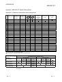
REVISIONS
The manual number is given on the bottom left of the back cover.
Print Date
Dec., 2003
Manual Number
SH(NA)-080436ENG-A First edition
Revision
Japanese Manual Version SH-080435-A
This manual confers no industrial property rights or any rights of any other kind, nor does it confer any patent
licenses. Mitsubishi Electric Corporation cannot be held responsible for any problems involving industrial property
rights which may occur as a result of using the contents noted in this manual.
2003 MITSUBISHI ELECTRIC CORPORATION
A-5
A-5
INTRODUCTION
Thank you for choosing the ST1H-PB MELSEC-ST PROFIBUS-DP head module.
Before using the module, please read this manual carefully to fully understand the functions and
performance of the ST1H-PB MELSEC-ST PROFIBUS-DP head module and use it correctly.
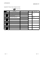
CONTENTS
SAFETY PRECAUTIONS..............................................................................................................................A- 1
REVISIONS ....................................................................................................................................................A- 5
CONTENTS....................................................................................................................................................A- 6
About Manuals ...............................................................................................................................................A- 9
Compliance with the EMC Directive and the Low Voltage Directive ............................................................A- 9
How to Read Manual......................................................................................................................................A-10
About the Generic Terms and Abbreviations ................................................................................................A-12
Term definition................................................................................................................................................A-13
Packing List ....................................................................................................................................................A-14
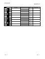
1 OVERVIEW
1- 1 to 1- 5
1.1 Features ................................................................................................................................................... 1- 2
2 SYSTEM CONFIGURATION
2- 1 to 2- 2
3 SPECIFICATIONS
3- 1 to 3-31
3.1 Performance Specifications ..................................................................................................................... 3- 1
3.2 Communication between Master Station and MELSEC-ST System ..................................................... 3- 3
3.2.1 Input data specifications.................................................................................................................... 3- 5
3.2.2 Output data specifications................................................................................................................. 3-14
3.2.3 I/O data used by head module.......................................................................................................... 3-23
3.3 Head Module Processing Time ............................................................................................................... 3-27
3.3.1 ST bus cycle time .............................................................................................................................. 3-28
3.3.2 Input transmission delay time ........................................................................................................... 3-30
3.3.3 Output transmission delay time ........................................................................................................ 3-31
4 FUNCTIONS
4- 1 to 4-32
4.1 Function List ............................................................................................................................................. 4- 1
4.2 Network Functions ................................................................................................................................... 4- 3
4.2.1 I/O data communication function ...................................................................................................... 4- 3
4.2.2 Global control function ...................................................................................................................... 4- 5
4.2.3 Extended diagnostic information notification function...................................................................... 4- 8
4.2.4 Swap function .................................................................................................................................... 4-11
4.2.5 I/O data consistency function............................................................................................................ 4-14
4.3 Control Functions ..................................................................................................................................... 4-17
4.3.1 Setting of output status at module error ........................................................................................... 4-17
4.3.2 Status monitor ................................................................................................................................... 4-19
4.3.3 Intelligent function module parameter read/write ............................................................................. 4-21
A-6
A-6
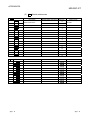
4.4 Online module change ............................................................................................................................. 4-22
4.4.1 Precautions for the online module change....................................................................................... 4-22
4.4.2 Procedures for online module change.............................................................................................. 4-24
4.4.3 Online module change using head module buttons......................................................................... 4-25
4.4.4 Online module change from GX Configurator-ST............................................................................ 4-28
5 PRE-OPERATION PROCEDURE AND SETTING
5- 1 to 5-13
5.1 Mounting and Installation......................................................................................................................... 5- 1
5.1.1 Handling precautions ........................................................................................................................ 5- 1
5.2 Pre-operation Procedure and Setting...................................................................................................... 5- 2
5.3 Part Names and Settings......................................................................................................................... 5- 3
5.3.1 Setting of FDL address setting switches .......................................................................................... 5- 6
5.3.2 Reset operation ................................................................................................................................. 5- 9
5.4 Self-diagnostics ........................................................................................................................................ 5-10
5.5 Wiring........................................................................................................................................................ 5-11
5.5.1 PROFIBUS cable wiring.................................................................................................................... 5-11
5.5.2 Wiring precautions............................................................................................................................. 5-13
6 PARAMETER SETTING
6- 1 to 6-12
6.1 Select Modules......................................................................................................................................... 6- 2
6.1.1 Selection and setting of maximum input/output points .................................................................... 6- 3
6.1.2 User parameter size.......................................................................................................................... 6- 4
6.1.3 Parameter setting example............................................................................................................... 6- 5
6.1.4 Word input/output points of intelligent function modules ................................................................. 6- 9
6.2 User Parameters ...................................................................................................................................... 6-12
7 PROGRAMMING
7- 1 to 7-33
7.1 When Using QJ71PB92D as Master Station .......................................................................................... 7- 1
7.1.1 Program example available when auto refresh is used in QJ71PB92D ......................................... 7-12
7.1.2 Program example available when auto refresh is not used in QJ71PB92D ................................... 7-19
7.2 When Using AJ71PB92D/A1SJ71PB92D as Master Station................................................................. 7-20
8 COMMANDS
8- 1 to 8-18
8.1 Command Overview ................................................................................................................................ 8- 1
8.2 Commands ............................................................................................................................................... 8- 4
8.2.1 Operating status read request (Command No.: 0100 H).................................................................. 8- 6
8.2.2 Error code read request (Command No.: 0101 H)............................................................................ 8-10
8.2.3 Error history read request (Command No.: 0102 H) ......................................................................... 8-14
8.3 Program Examples .................................................................................................................................. 8-15
8.4 Values Stored into Command Execution Result..................................................................................... 8-17
A-7
A-7
9 TROUBLESHOOTING
9- 1 to 9-16
9.1 When I/O data cannot be communicated................................................................................................ 9- 2
9.1.1 When RUN LED is off ....................................................................................................................... 9- 4
9.1.2 When BF LED is on........................................................................................................................... 9- 5
9.1.3 When input data is erroneous........................................................................................................... 9- 6
9.1.4 When output data is erroneous......................................................................................................... 9- 7
9.2 When ERR. LED is on or flickering ......................................................................................................... 9- 8
9.2.1 Error code reading operation ............................................................................................................ 9- 8
9.2.2 Error code list .................................................................................................................................... 9-10
9.3 When command cannot be executed...................................................................................................... 9-15
APPENDICES
App- 1 to App-15
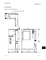
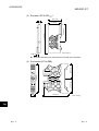
Appendix 1 External Dimensions ..............................................................................................................App- 1
Appendix 2 MELSEC-ST System Setting Sheet.......................................................................................App- 3
Appendix 2.1 Maximum input/output points setting sheet ....................................................................App- 3
Appendix 2.2 Input data assignment sheet ...........................................................................................App- 4
Appendix 2.3 Output data assignment sheet ........................................................................................App-10
INDEX
A-8
Index- 1 to Index- 2
A-8
About Manuals
The following manuals are related to this product.
Referring to this list, please request the necessary manuals.
Relevant Manuals
Manual Name
MELSEC-ST System User's Manual
Explains the system configuration of the MELSEC-ST system and the performance
specifications, functions, handling, wiring and troubleshooting of the power
distribution modules, base modules and I/O modules. (Sold separately)
GX Configurator-ST Version 1 Operating Manual
Explains how to operate GX Configurator-ST, how to set the intelligent function
module parameters, and how to monitor the MELSEC-ST system. (Sold separately)
Manual Number
(Model Code)
SH-080456ENG
(13JR72)
SH-080439ENG
(13JU47)
Compliance with the EMC Directive and the Low Voltage Directive
When incorporating the Mitsubishi MELSEC-ST system that is compliant with the
EMC directive and the low voltage directive into other machine or equipment and
making it comply with the EMC directive and the low voltage directive, refer to "EMC
Directive and Low Voltage Directive" of the MELSEC-ST System User's Manual.
The CE logo is printed on the rating plate of the MELSEC-ST system products
compliant to the EMC Directive and the Low Voltage Directive.
For making this product comply with the EMC directive and the low voltage directive,
please refer to "EMC Directive and Low Voltage Directive" of the MELSEC-ST
System User's Manual.
A-9
A-9
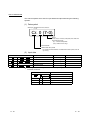
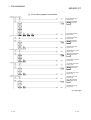
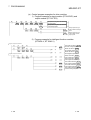
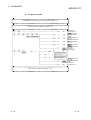
How to Read Manual
This manual explains each area for input data and output data using the following
symbols.
(1) Data symbol
<Example: Cr Command result area>
Cr. 0 (7-0)
Range
In the case of 1-word (16 bit) data, this shows the
corresponding range.
(0) : Shows 0 bit position
(7-0): Shows 0-7 bit range
Detail data No.
Abbreviated data symbol
For details of detail data No. and abbreviated data symbol, refer to
(2) and (3)
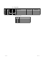
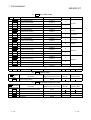
(2) Input data
Br
Data symbol
Br.00 to Br.FF
Er
Er.00 to Er.FF
Error Information Area
Mr
Mr.0 to Mr.127
Module Status Area
Cr
Wr
1
Wr.00 to Wr.33
Area
Bit Input Area
Unit
1 bit/1 signal
Detail data No. notation
Hexadecimal
1 bit/1 signal
Hexadecimal
Command Result Area
Word Input Area
1 bit/1 signal
Decimal
1 word/1 signal
Decimal
1 word/1 signal
Hexadecimal
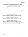
1: Following shows the data symbols and the corresponding detail areas within the
command result area.
Data symbol
Area
Cr.0 (15 - 8) Command Execution Area
Cr.0
Cr.0 (7 - 0) Start Slice No. of Execution Target
A - 10
Cr.1
Executed Command No.
Cr.2
Response Data 1
Cr.3
Response Data 2
A - 10
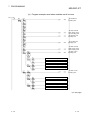
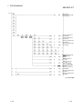
(3) Output data
Bw
Data symbol
Bw.00 to Bw.FF
Ew
Ew.00 to Ew.FF
Sw
Sw.0 to Sw.7
Cw
Ww
1
Ww.00 to Ww.33
Area
Bit Output Area
Unit
1 bit/1 signal
Detail data No. notation
Hexadecimal
Error Clear Area
1 bit/1 signal
Hexadecimal
System Area
1 word/1 signal
Decimal
Command Execution Area
1 word/1 signal
Decimal
Word Output Area
1 word/1 signal
Hexadecimal
1: Following shows the data symbols and the corresponding detail areas within the
command execution area.
Data
symbol
Cw.0
A - 11
Area
Start Slice No. of Execution Target
Cw.1
Command No. to be Executed
Cw.2
Argument 1
Cw.3
Argument 2
A - 11
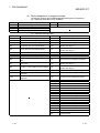
About the Generic Terms and Abbreviations
Unless otherwise specified, this manual uses the following generic terms and
abbreviations to explain the head module.
Description
Generic Term/Abbreviation
Head module
ST1H-PB, MELSEC-ST PROFIBUS-DP compatible head module.
PROFIBUS-DP
PROFIBUS-DP network.
Bus refreshing module
Module that distributes the external SYS. power supply and external AUX. power supply
among the head module and slice modules.
Power feeding module
Module that distributes external AUX. power supply among slice modules.
Power distribution module
Bus refreshing module and Power feeding module.
Base module
Module that transfers data/connects between the head module and slice modules, and
between slice modules and external devices.
Input module
Module that handles input data in bit units.
Output module
Module that handles output data in bit units.
Intelligent function module
Module that handles input/output data in word units.
I/O module
Input module and output module.
Slice module
Module that can be mounted to the base module: power distribution module, I/O module and
intelligent function module.
MELSEC-ST system
System that consists of head module, slice modules, end plates and end brackets.
GX Configurator-ST
SWnD5C-STPB-E type products. (n: 1 or later)
Configuration software
Software used to set slave parameters for head module and slice modules.(e.g., GX
Configurator-DP)
A - 12
A - 12
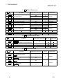
Term definition
The following explains the meanings and definitions of the terms used in this manual.
Term
Definition
Master station
Class 1 master station that communicates I/O data with slave stations.
Slave station
Device that communicates I/O data with the master station.
Repeater
Device that connects PROFIBUS-DP segments.
Bus terminator
Terminator that is connected to both ends of each PROFIBUS-DP segment
FDL address
Address assigned to the master station/slave station.
Extended diagnostic
information
Information that is notified from the slave station to the master station when an error occurs at a
slave station.
Slave parameter
The slave station parameter (including user parameter) set by the master station.
The setting items are described in the GSD file.
GSD file
The electronic file that includes description of the slave station parameter.
The file is used to set slave parameters by the master station.
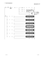
Data sent from the head module to the master station.
The data consists of the following areas.
Br Bit Input Area
Input data
Output data
I/O data
Br.n bit input
Information Area
Er Error Information Area
Mr Module Status Area
Cr Command Result Area
Wr Word Input Area
Data that the head module receives from the master station.
The data consists of the following areas.
Bw Bit Output Area
Request Area
Ew Error Clear Area
Sw System Area
Cw Command Execution Area
Ww Word Output Area
Data (input data, output data) transferred between the head module and the master station.
Bit input data of each module.
Bw.n bit output
Bit output data of each module
Wr.n word input
Word (16-bit) input data of an intelligent function module.
In the case of analog input module, the digital output data value is stored.
Ww.n word output
Word (16-bit) output data of an intelligent function module.
In the case of analog output module, the digital setting data value is stored.
Information area
Bit/Word input data for checking each module status and command execution results.
Request area
Bit/Word output data for requesting each module to clear errors/to execute commands.
The area, that is equivalent to the occupied I/O points, is occupied in Br Bit Input Area/ Bw Bit
Output Area.
Number of occupied I/O
points
Slice No.
No. assigned to every 2 occupied I/O points of each module. This numbering starts by assigning
"0" to the head module and then proceeds in ascending order. (The maximum value No. is 127).
The No. is used for specifying the execution target.
Command
Requesting from the master station in order to read the module status, to set/control the intelligent
function module command parameters.
ST bus cycle time
Processing time for the head module to refresh the input/output status of each slice module.
Bus cycle time
PROFIBUS-DP processing time for the master station to perform cyclic transfer with each slave
station.
A - 13
A - 13
Packing List
The following gives the packing list of the head module.
Model name
Product
Quantity
ST1H-PB
ST1H-PB MELSEC-ST PROFIBUS-DP head module
1
ST1A-EPL
ST1A-EPL end plate
1
ST1A-EBR
ST1A-EBR end bracket
2
A - 14
A - 14
1 OVERVIEW
MELSEC-ST
1 OVERVIEW
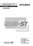
This manual explains the specifications, functions, pre-operation procedures and
troubleshooting of the ST1H-PB MELSEC-ST PROFIBUS-DP head module (hereafter
referred to as the head module).
The head module is used to connect a MELSEC-ST system to a PROFIBUS-DP
network. (The head module operates as a slave station of a PROFIBUS-DP network.)
<System using QJ71PB92D>
GSD file
Class 1 master station (QJ71PB92D)
GX Configurator-DP
Bus terminator
Slave station
Slave station
Slave station (MELSEC-ST system)
GX Configurator-ST
Slave station
Slave station (MELSEC-ST system)
Bus terminator
Slave station
1-1
1-1
1
1 OVERVIEW
MELSEC-ST
1.1 Features
1
The head module has the following features.
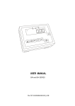
(1) MELSEC-ST system can be connected to PROFIBUS-DP network
By mounting this module as the head module of a MELSEC-ST system, the
MELSEC-ST system can be connected to the PROFIBUS-DP network.
The head module complies with EN50170 Volume 2 (Part 1, 2, 3, 4, 8) and
communicates with the master station as a PROFIBUS-DP slave station.
Class 1 master
station
Slave station
No. 1
Slave station
No. 2
MELSEC-ST
Slave station
No. 30
Class 1 master
station
Input image
Input data
Output image
Head module
Input sending
area
Slice
module
Slice
module
Output data
Output receiving
area
1-2
1-2
1 OVERVIEW
MELSEC-ST
(2) Controlling the MELSEC-ST system
The head module receives data output from the master station, stores the data
into the output receiving area, and uses them to control each slice module.
Also, the head module gathers various information such as the input status data
from each slice module into the input sending area, and sends them to the
master station as input data.
Head module
Sent to master station
Input sending area
Slice module
Input
status
Slice module
Input
status
Output receiving
area
Output
status
Output
status
Received from master station
(3) Functions for communication with master station
Using the following functions, the head module can communicate with the master
station.
(a) I/O data size selection
The head module uses input data (head module master station) and
output data (master station head module) to communicate with the
master station.
By selecting the maximum input/output points appropriate for the MELSECST system configuration on the head module, the input/output data
communicated with the master station can be adjusted to the optimum size.
Also, the maximum I/O points can be set to a slightly larger size for future
expansion of the MELSEC-ST system. (Refer to Section 6.1.1.)
(b) Supporting the global control functions
The head module supports the global control functions.
Using the commands (SYNC, UNSYNC, FREEZE, UNFREEZE) sent by
the master station, the refresh of the head module I/O data can be
controlled from the master station. (Refer to Section 4.2.2.)
(c) Extended diagnostic information notification function
When an error occurs in a slice module, the master station can be notified
of the error as extended diagnostic information.
When the slice module is restored to normal, the master station is also
notified of it. (Refer to Section 4.2.3.)
(d) Swapping of I/O data or extended diagnostic information bytes
When I/O data are sent to or received from the master station or when
extended diagnostic information is sent to the master station, their high and
low bytes can be swapped in word units.
This function eliminates the need for a high/low byte swapping program on
the master station side, simplifying the program. (Refer to Section 4.2.4.)
1-3
1-3
1 OVERVIEW
MELSEC-ST
(4) Controlling various slice modules
The head module can control various MELSEC-ST slice modules in the same
system.
(a) Up to 63 slice modules can be mounted
The head module accepts up to 63 slice modules (up to 26 intelligent
function modules).
(b) Error status and mounting status of each slice module can be
checked
In each of input data area in the head module, the error status, mounting
status, etc. of each slice module can be checked.
(c) Commands can be executed from master station
By executing commands from the master station using the command
execution area of output data, the following is available.
Confirming the operating statuses of the head module and each slice
module
Reading error codes of the head module and/or each slice module
Reading the head module error history
Setting intelligent function module command parameters
(d) Output status at module error
Whether the refresh of output data to the other normally-operating slice
module will be stopped or continued when an error occurs in a slice module
can be preset. (Refer to Section 4.3.1.)
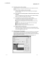
(5) GX Configurator-ST available
Using the personal computer where optional GX Configurator-ST is preinstalled
and connecting it to the head module, such operations as parameter setting,
system monitor, forced output test and online module change can be performed
easily for the MELSEC-ST system.
Refer to Section 4.1 for the functions available for GX Configurator-ST.
1-4
1-4
1 OVERVIEW
MELSEC-ST
(6) Online module change
The I/O modules and intelligent function modules can be replaced without
stopping the MELSEC-ST system. (Refer to Section 4.4.)
1-5
1-5
2 SYSTEM CONFIGURATION
MELSEC-ST
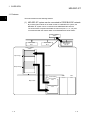
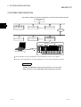
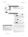
2 SYSTEM CONFIGURATION
This chapter explains the system configuration in which the head module is used.
Class 1 master
station
2
MELSEC-ST
Slave station No. 1
Slave station No. 2
Slave station No. 30
Repeater
Slave station No. 31
MELSEC-ST
Slave station No. 60
Slave station No. 32
MELSEC-ST system 1
ST1PSD
ST1H-PB
RUN
SYS
AUX.
ERR
ST1PDD
RUN
11
ERR
21
RUN
11
ERR
21
RUN
11
ERR
21
RUN
31
41
51
61
71
81
91
101
111
121
131
141
151
ERR
RUN
ERR
RUN
ERR
161
AUX
RELEASE
RESET
PROFIBUS I/F
QC30R2, etc. 2
GX Configurator-ST 2
1: For the MELSEC-ST system configuration, refer to the MELSEC-ST System User’s Manual.
2: For the system configuration for use of GX Configurator-ST, refer to the GX Configurator-ST Manual.
REMARK
Prepare the PROFIBUS cable and bus terminator on the user side.
Refer to Section 5.5 for PROFIBUS cable wiring and bus terminal.
2-1
2-1
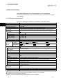
2 SYSTEM CONFIGURATION
MELSEC-ST
MEMO
2
2-2
2-2
3 SPECIFICATIONS
MELSEC-ST
3 SPECIFICATIONS
This chapter explains the performance specifications of the head module.
For the general specifications of the head module, refer to the MELSEC-ST System
User's Manual.
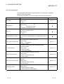
3.1 Performance Specifications
This section explains the performance specifications of the head module.
3
Item
Specifications
PROFIBUS-DP station type
Slave station (compliant with EN50170 Volume 2 (Part 1, 2, 3, 4, 8))
Applicable FDL address
0 to 99
Maximum input/output points
32-point mode/64-point mode/128-point mode/256-point mode
1
I/O data size
Varies depending on the maximum input output points. (Refer to (1) in this section)
Maximum number of connected
slice modules
In 32-point mode
14 modules
2
In 64-point mode
30 modules
2
In 128-point mode
62 modules
2
In 256-point mode
63 modules
2
Number of occupied I/O points
4 input and 4 output points
Number of occupied slices
2
Br.n : Number of occupancy 4, Er.n : Number of occupancy 4, Mr.n : Number of
occupancy 2, Wr.n : Number of occupancy 0
Information
amount
Input data
Output data
Transmission specifications
Electrical standards and
characteristics
Applicable cable
Bw.n : Number of occupancy 4, Ew.n : Number of occupancy 4, Ww.n : Number of
occupancy 0
EIA-RS485 compliant
Shielded twisted pair cable (Type A)
3
Network configuration
Bus type (tree type when repeaters are used)
Data link method
Transmission encoding
method
Polling
Transmission speed
9.6kbps to 12Mbps (refer to (2) in this section)
Transmission distance
Maximum number of
repeaters
4
NRZ
Varies depending on the transmission speed. (refer to (2) in this section)
3 repeaters per network
Maximum number of stations 32 stations (including repeaters) per segment
Number of connection nodes 32 nodes per segment
5V DC internal current
0.530A
consumption
External dimensions
114.5 (4.51 in.) (H)
50.5 (1.99 in.) (W)
74.5 (2.93 in.) (D) [mm]
Weight
0.10 kg
1: Factory-set to "FDL address 0".
2: Configure the system within the range where the conditions in Section 6.1 (1) are satisfied.
3: Refer to Section 5.5.1 for details of the cable.
4: Within 0.3% for transmission speed control (EN50170 Volume 2 compliant)
3-1
3-1
3 SPECIFICATIONS
MELSEC-ST
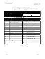
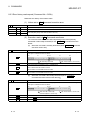
(1) I/O data sizes
The following table indicates the data sizes for maximum input/output points.
Refer to Section 3.2.1 and Section 3.2.2 for the I/O data offset addresses.
Maximum
input/output
points
32-point mode
64-point mode
128-point mode
256-point mode
Input
Output
Input
Output
Input
Output
Input
Output
32 bits
32 bits
64 bits
64 bits
128 bits
128 bits
256 bits
256 bits
Max. 52
Max. 52
Max. 52
Max. 52
Max. 52
Max. 52
Max. 32
Max. 32
words
words
words
words
words
words
words
words
Item
Bit I/O points
Word I/O points
(Variable) (Variable) (Variable) (Variable) (Variable) (Variable) (Variable) (Variable)
Request/Information area
Total
14 bytes
14 bytes
20 bytes
20 bytes
32 bytes
32 bytes
56 bytes
56 bytes
Max. 122
Max. 122
Max. 132
Max. 132
Max. 152
Max. 152
Max. 152
Max. 152
bytes
bytes
bytes
bytes
bytes
bytes
bytes
bytes
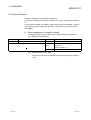
(2) Transmission distance
Transmission speed
Transmission distance [m/segment]
Maximum transmission distance when using
repeater [m/network]
1
9.6kbps
19.2kbps
1200m(3937 ft.)/segment
4800m(15748 ft.)/network
187.5kbps
1000m(3281 ft.)/segment
4000m(13123 ft.)/network
500kbps
400m(1312 ft.)/segment
1600m(5249 ft.)/network
1.5Mbps
200m(656 ft.)/segment
800m(2625 ft.)/network
100m(328 ft.)/segment
400m(1312 ft.)/network
45.45kbps
93.75kbps
3Mbps
6Mbps
12Mbps
1: The maximum transmission distance in the above table is based on the example of using 3 repeaters.
Use the following expression when increasing the transmission distance using repeaters.
Maximum transmission distance [m/number of networks] =
(number of repeaters + 1)
3-2
transmission distance [m/segment]
3-2
3
3 SPECIFICATIONS
MELSEC-ST
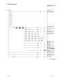
3.2 Communication between Master Station and MELSEC-ST System
For communication between the master station and MELSEC-ST system, use input
data sent from the head module to the master station and output data sent from the
master station to the head module.
Class 1 master station
Input image for FDL
address 1
Input image for FDL
address 2 1
Input image
Input image for FDL
address 3
(continued)
Output image for FDL
address 1
Output image for FDL
address 2 1
Output image
3)
Output image for FDL
address 3
(continued)
MELSEC-ST system (Slave station, FDL address 2)
A)
Slice
module
Head module
Input sending area
Slice
module
Information
area
Br Bit input area
Input
status
Er Error information area
Mr Module status area
2)
Cr Command result area
Wr Word input area
Output receiving area
Request
area
Bw Bit output area
Ew Error Clear Area
Sw System Area
Output
status
1)
B)
Cw Command execution area
Ww Word output area
C)
1: The data sizes of the input and output images for MELSEC-ST system
differ depending on the maximum input/output points.
Refer to Section 3.2.1 and 3.2.2 for details.
3-3
3-3
3 SPECIFICATIONS
MELSEC-ST
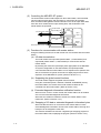
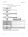
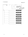
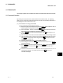
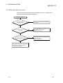
[Processing outline of MELSEC-ST system Master station]
1) The status data of the external device are imported to the input status area of
the slice module.
2) The input status data of each slice module is stored into the input sending area
of the head module.
3) The input data in the input sending area is sent to the corresponding input
image area in the master station.
[Processing outline of Master station MELSEC-ST system]
A) The corresponding output image is sent from the master station to the head
module.
B) The output data received in the output receiving area of the head module is
refreshed to the output status area of the corresponding slice module.
C) The output status data of the slice module is output to the external device.
(1) Input data
The following table indicates the construction of input data.
Refer to Section 3.2.1 and Section 3.2.3 for the data sizes of input data, the
details of the areas, and the areas used by the head module.
Data name
Stores the ON/OFF information of Br.n Bit inputs entered from
Br Bit input area
the head module and slice modules.
Er Error information
area
Input data
Information area
Description
Mr Module status
area
Cr Command result
area
Wr Word input area
Stores the statuses (error information) of the head module and
slice modules.
Stores the information of the slice modules recognized by the
head module.
Stores the results of executing a command to the head module or
corresponding slice module.
Stores Wr.n Word input values received from the intelligent
function modules in order of the mounted position.
(2) Output data
The following table indicates the construction of output data.
Refer to Section 3.2.2 and Section 3.2.3 for the data sizes of output data, the
details of the areas, and the areas used by the head module.
Data name
Bw Bit output area
Output data Request area
Ew Error clear
area
Sw System area
Cw Command
execution area
Ww Word output area
3-4
Description
Stores the ON/OFF information of Bw.n Bit outputs
provided to the head module and slice modules.
Stores the error information clear requests of the head
module and slice modules.
System area used by the head module.
Stores the command for controlling the head module or
corresponding slice module.
Stores Ww.n Word output values sent to the intelligent
function modules in order of the mounted position.
3-4
3 SPECIFICATIONS
MELSEC-ST
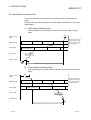
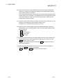
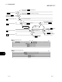
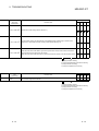
3.2.1 Input data specifications
This section explains the data sizes of input data and the details of each area.
POINT
In this manual, input data addresses (input image addresses on the master station
side) are indicated as offset addresses (word unit).
[Offset address]
Denotes a data position in word units, relative to the first address of the input
image assigned for the MELSEC-ST system on the master station side.
(1) Input data sizes
The input data sizes differ depending on the setting of the maximum I/O points.
The input data sizes for the maximum I/O points are indicated below.
Refer to Section 6.1 for details of the maximum I/O points.
(a) 32-point mode
Offset
address
(Decimal)
+0
+1
+2
+3
+4
Application
Data size
Br.00 to Br.1F
Br Bit input area
2 words
Refer to (2) in this section.
Er.00 to Er.1F
Er Error information area
2 words
Refer to (3) in this section.
Mr.0 to Mr.15
Mr Module status area
1 word
Refer to (4) in this section.
Cr.0 to Cr.3
Cr Command result area
4 words
Refer to (5) in this section.
Wr.00 to Wr.33
Wr Word input area
Minimum size : 0 words
Maximum size: 52 words
+5
to
+8
+9
to
+60
Size variable 1
Refer to (6) in
this section.
1: The data size of the Wr Word input area is a sum total of the Wr Word input area
sizes used by the mounted intelligent function modules.
This data size is 0 when no intelligent function modules are mounted.
3-5
3-5
3 SPECIFICATIONS
MELSEC-ST
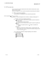
(b) 64-point mode
Offset
address
(Decimal)
Application
Data size
+0
Br.00 to Br.3F
Br Bit input area
4 words
Refer to (2) in this section.
to
Er.00 to Er.3F
Er Error information area
4 words
Refer to (3) in this section.
+7
+8
+9
+10
Mr.0 to Mr.31
Mr Module status area
2 words
Refer to (4) in this section.
to
Cr.0 to Cr.3
Cr Command result area
4 words
Refer to (5) in this section.
Wr.00 to Wr.33
Wr Word input area
Minimum size : 0 words
Maximum size: 52 words
to
+3
+4
+13
+14
to
Size variable 1
+65
Refer to (6) in
this section.
1: The data size of the Wr Word input area is a sum total of the Wr Word input area
sizes used by the mounted intelligent function modules.
This data size is 0 when no intelligent function modules are mounted.
(c) 128-point mode
Offset
address
(Decimal)
Application
Data size
+0
to
Br.00 to Br.7F
Br Bit input area
8 words
Refer to (2) in this section.
Er.00 to Er.7F
Er Error information area
8 words
Refer to (3) in this section.
Mr.0 to Mr.63
Mr Module status area
4 words
Refer to (4) in this section.
Cr.0 to Cr.3
Cr Command result area
4 words
Refer to (5) in this section.
Wr.00 to Wr.33
Wr Word input area
Minimum size : 0 words
Maximum size: 52 words
+7
+8
to
+15
+16
to
+19
+20
to
+23
+24
to
+75
Size variable 1
Refer to (6) in
this section.
1: The data size of the Wr Word input area is a sum total of the Wr Word input area
sizes used by the mounted intelligent function modules.
This data size is 0 when no intelligent function modules are mounted.
3-6
3-6
3 SPECIFICATIONS
MELSEC-ST
(d) 256-point mode
Offset
address
(Decimal)
Application
Data size
+0
to
Br.00 to Br.FF
Br Bit input area
16 words
Refer to (2) in this section.
Er.00 to Er.FF
Er Error information area
16 words
Refer to (3) in this section.
Mr.0 to Mr.127
Mr Module status area
8 words
Refer to (4) in this section.
Cr.0 to Cr.3
Cr Command result area
4 words
Refer to (5) in this section.
Wr.00 to Wr.1F
Wr Word input area
Minimum size : 0 words
Maximum size: 32 words
+15
+16
to
+31
+32
to
+39
+40
to
+43
+44
to
+95
Size variable 1
Refer to (6) in
this section.
1: The data size of the Wr Word input area is a sum total of the Wr Word input area
sizes used by the mounted intelligent function modules.
This data size is 0 when no intelligent function modules are mounted.
3-7
3-7
3 SPECIFICATIONS
MELSEC-ST
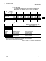
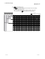
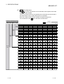
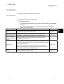
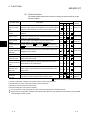
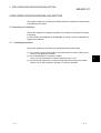
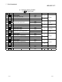
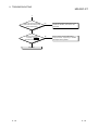
(2)
Br Bit input area
The Br Bit input area stores the ON/OFF information of the Br.n bit inputs
entered from the head module and slice modules.
Each of the head module and slice modules occupies 2 bits per slice.
The construction of the Br Bit input area is shown below.
Maximum input/output points
2561286432point point point point
mode mode mode mode
Slice No.
Br Bit input area
b15
b0
Br.0F
Used
area
Used
area
Br.0E
Br.0D
Br.1E
Br.1D
Br.2E
Br.2D
Br.3E
Br.3D
Br.4E
Br.4D
7
Br.1F
Used
area
Br.5E
Used
area
Br.6E
Br.8E
Br.8D
Br.9E
Br.9D
Br.AE
Br.AD
Br.BE
Br.BD
Br.CE
Br.CD
111
Br.EF
Br.EE
119
Br.FF
Br.FE
127
3-8
Br.5C
Br.6C
Br.5B
Br.6B
Br.7C
Br.7B
Br.8C
Br.8B
Br.39
Br.4A
Br.49
Br.9C
Br.9B
Br.AC
Br.AB
Br.BC
Br.BB
Br.CC
Br.CB
Br.5A
Br.6A
118
Br.FC
126
Br.59
Br.69
Br.7A
Br.79
Br.8A
Br.89
Br.37
Br.48
Br.47
Br.9A
Br.99
Br.AA
Br.A9
Br.BA
Br.B9
Br.CA
Br.C9
Br.58
Br.68
117
Br.FA
125
Br.67
Br.77
Br.88
Br.87
Br.35
Br.46
Br.45
Br.98
Br.97
Br.A8
Br.A7
Br.B8
Br.B7
Br.C8
Br.C7
Br.56
Br.66
116
Br.F8
124
Br.55
Br.65
Br.76
Br.75
Br.86
Br.85
Br.33
Br.44
Br.43
Br.96
Br.95
Br.A6
Br.A5
Br.B6
Br.B5
Br.C6
Br.C5
Br.D6
Br.D5
Br.54
Br.64
123
Br.63
Br.73
Br.84
Br.83
Br.31
Br.42
Br.41
Br.94
Br.93
Br.A4
Br.A3
Br.B4
Br.B3
Br.C4
Br.C3
Br.D4
Br.D3
Br.52
Br.62
122
Br.61
Br.72
Br.71
Br.82
Br.81
Br.60
Br.92
Br.91
Br.A2
Br.A1
Br.B2
Br.B1
Br.C2
Br.C1
Br.D2
Br.D1
Br.70
56
Br.80
64
Br.90
72
Br.A0
80
Br.B0
88
97
Br.C0
96
105
Br.E2
113
Br.F3
Br.50
48
89
Br.F4
Br.51
40
81
114
Br.40
32
73
Br.E3
Br.30
24
65
Br.E4
Br.20
16
57
106
Br.F5
Br.53
Br.74
98
Br.F6
Br.32
Br.10
8
49
90
115
Br.21
41
82
Br.E5
Br.22
Br.00
0
33
74
Br.E6
Br.11
25
66
107
Br.12
17
58
99
Br.F7
Br.34
Br.01
9
50
91
Br.E7
Br.23
42
83
Br.E8
Br.24
Br.02
1
34
75
Br.D7
Br.13
26
67
Br.D8
Br.14
18
59
108
Br.F9
Br.57
Br.78
100
Br.E9
Br.36
Br.03
10
51
92
Br.EA
Br.25
43
84
109
Br.26
Br.04
2
35
76
Br.D9
Br.15
27
68
Br.DA
Br.16
19
60
101
Br.FB
Br.38
Br.05
11
52
93
Br.EB
Br.27
44
85
Br.EC
Br.28
Br.06
3
36
77
Br.DB
Br.17
28
69
Br.DC
Br.18
20
61
110
Br.FD
Br.3A
Br.07
12
53
102
Br.ED
Br.29
45
94
Br.DD
Br.2A
Br.08
4
37
86
Br.DE
Br.19
29
78
103
Br.DF
Br.4B
70
95
Br.CF
Br.4C
Br.1A
21
62
87
Br.BF
Br.6D
Br.7D
79
Br.AF
Br.5D
Br.7E
71
Br.9F
Br.3B
54
63
Br.8F
Br.3C
Br.09
13
46
55
Br.7F
Br.2B
38
47
Br.6F
Br.2C
Br.0A
5
30
39
Br.5F
Br.1B
22
31
Br.4F
Br.1C
14
23
Br.3F
Br.0B
6
15
Br.2F
Br.0C
Br.F2
121
Br.D0
104
Br.E1
Br.E0
112
Br.F1
Br.F0
120
3-8
3 SPECIFICATIONS
MELSEC-ST
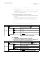
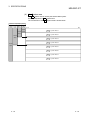
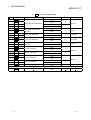
(3)
Er Error information area
The Er Error information area stores the statuses (error information) of the head
module and slice modules.
Each of the head module and slice modules occupies 2 bits per slice.
The construction of the Er Error information area is shown below.
Maximum input/output points
2561286432point point point point
mode mode mode mode
Slice No.
Er Error information area
b15
b0
Er.0F
Used
area
Used
area
Er.0E
Er.0D
Er.1E
Er.1D
Er.2E
Er.2D
Er.3E
Er.3D
Er.4E
Er.4D
7
Er.1F
Used
area
Er.5E
Used
area
Er.6E
Er.8E
Er.8D
Er.9E
Er.9D
Er.AE
Er.AD
Er.BE
Er.BD
Er.CE
Er.CD
111
Er.EF
Er.EE
119
Er.FF
Er.FE
127
3-9
Er.5C
Er.6C
Er.5B
Er.6B
Er.7C
Er.7B
Er.8C
Er.8B
Er.39
Er.4A
Er.49
Er.9C
Er.9B
Er.AC
Er.AB
Er.BC
Er.BB
Er.CC
Er.CB
Er.5A
Er.6A
118
Er.FC
126
Er.59
Er.69
Er.7A
Er.79
Er.8A
Er.89
Er.37
Er.48
Er.47
Er.9A
Er.99
Er.AA
Er.A9
Er.BA
Er.B9
Er.CA
Er.C9
Er.58
Er.68
117
Er.FA
125
Er.67
Er.77
Er.88
Er.87
Er.35
Er.46
Er.45
Er.98
Er.97
Er.A8
Er.A7
Er.B8
Er.B7
Er.C8
Er.C7
Er.56
Er.66
116
Er.F8
124
Er.55
Er.65
Er.76
Er.75
Er.86
Er.85
Er.33
Er.44
Er.43
Er.96
Er.95
Er.A6
Er.A5
Er.B6
Er.B5
Er.C6
Er.C5
Er.D6
Er.D5
Er.54
Er.64
123
Er.63
Er.73
Er.84
Er.83
Er.31
Er.42
Er.41
Er.94
Er.93
Er.A4
Er.A3
Er.B4
Er.B3
Er.C4
Er.C3
Er.D4
Er.D3
Er.52
Er.62
122
Er.61
Er.72
Er.71
Er.82
Er.81
Er.60
Er.92
Er.91
Er.A2
Er.A1
Er.B2
Er.B1
Er.C2
Er.C1
Er.D2
Er.D1
Er.70
56
Er.80
64
Er.90
72
Er.A0
80
Er.B0
88
97
Er.C0
96
105
Er.E2
113
Er.F3
Er.50
48
89
Er.F4
Er.51
40
81
114
Er.40
32
73
Er.E3
Er.30
24
65
Er.E4
Er.20
16
57
106
Er.F5
Er.53
Er.74
98
Er.F6
Er.32
Er.10
8
49
90
115
Er.21
41
82
Er.E5
Er.22
Er.00
0
33
74
Er.E6
Er.11
25
66
107
Er.12
17
58
99
Er.F7
Er.34
Er.01
9
50
91
Er.E7
Er.23
42
83
Er.E8
Er.24
Er.02
1
34
75
Er.D7
Er.13
26
67
Er.D8
Er.14
18
59
108
Er.F9
Er.57
Er.78
100
Er.E9
Er.36
Er.03
10
51
92
Er.EA
Er.25
43
84
109
Er.26
Er.04
2
35
76
Er.D9
Er.15
27
68
Er.DA
Er.16
19
60
101
Er.FB
Er.38
Er.05
11
52
93
Er.EB
Er.27
44
85
Er.EC
Er.28
Er.06
3
36
77
Er.DB
Er.17
28
69
Er.DC
Er.18
20
61
110
Er.FD
Er.3A
Er.07
12
53
102
Er.ED
Er.29
45
94
Er.DD
Er.2A
Er.08
4
37
86
Er.DE
Er.19
29
78
103
Er.DF
Er.4B
70
95
Er.CF
Er.4C
Er.1A
21
62
87
Er.BF
Er.6D
Er.7D
79
Er.AF
Er.5D
Er.7E
71
Er.9F
Er.3B
54
63
Er.8F
Er.3C
Er.09
13
46
55
Er.7F
Er.2B
38
47
Er.6F
Er.2C
Er.0A
5
30
39
Er.5F
Er.1B
22
31
Er.4F
Er.1C
14
23
Er.3F
Er.0B
6
15
Er.2F
Er.0C
Er.F2
121
Er.D0
104
Er.E1
Er.E0
112
Er.F1
Er.F0
120
3-9
3 SPECIFICATIONS
MELSEC-ST
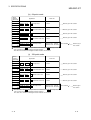
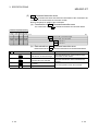
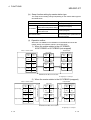
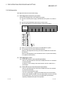
(4)
Mr Module Status area
The Mr Module Status area stores the information of the slice modules
recognized by the head module.
Each of the head module and slice modules occupies 1 bit per slice.
The construction of the Mr Module Status area is shown below.
Maximum input/output points
2561286432point point point point
mode mode mode mode
Used
area
Used
area
Used
area
Used
area
Slice No.
Mr Module status
b15
Mr.15
b0
Mr.14
Mr.13
Mr.12
Mr.11
Mr.10
Mr.9
Mr.8
Mr.7
Mr.6
Mr.5
Mr.4
Mr.3
Mr.2
Mr.1
Mr.0
15
14
13
12
11
10
9
8
7
6
5
4
3
2
1
0
Mr.31
Mr.30
Mr.29
Mr.28
Mr.27
Mr.26
Mr.25
Mr.24
Mr.23
Mr.22
Mr.21
Mr.20
Mr.19
Mr.18
Mr.17
Mr.16
31
30
29
28
27
26
25
24
23
22
21
20
19
18
17
16
Mr.47
Mr.46
Mr.45
Mr.44
Mr.43
Mr.42
Mr.41
Mr.40
Mr.39
Mr.38
Mr.37
Mr.36
Mr.35
Mr.34
Mr.33
Mr.32
47
46
45
44
43
42
41
40
39
38
37
36
35
34
33
32
Mr.63
Mr.62
Mr.61
Mr.60
Mr.59
Mr.58
Mr.57
Mr.56
Mr.55
Mr.54
Mr.53
Mr.52
Mr.51
Mr.50
Mr.49
Mr.48
63
62
61
60
59
58
57
56
55
54
53
52
51
50
49
48
Mr.79
Mr.78
Mr.77
Mr.76
Mr.75
Mr.74
Mr.73
Mr.72
Mr.71
Mr.70
Mr.69
Mr.68
Mr.67
Mr.66
Mr.65
Mr.64
79
78
77
76
75
74
73
72
71
70
69
68
67
66
65
64
Mr.95
Mr.94
Mr.93
Mr.92
Mr.91
Mr.90
Mr.89
Mr.88
Mr.87
Mr.86
Mr.85
Mr.84
Mr.83
Mr.82
Mr.81
Mr.80
95
94
93
92
91
90
89
88
87
86
85
84
Mr.111 Mr.110 Mr.109 Mr.108 Mr.107 Mr.106 Mr.105 Mr.104 Mr.103 Mr.102 Mr.101 Mr.100
111
110
109
108
107
106
105
104
103
102
101
100
83
82
81
80
Mr.99
Mr.98
Mr.97
Mr.96
99
98
97
96
Mr.127 Mr.126 Mr.125 Mr.124 Mr.123 Mr.122 Mr.121 Mr.120 Mr.119 Mr.118 Mr.117 Mr.116 Mr.115 Mr.114 Mr.113 Mr.112
127
3 - 10
126
125
124
123
122
121
120
119
118
117
116
115
114
113
112
3 - 10
3 SPECIFICATIONS
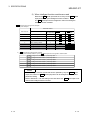
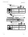
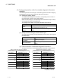
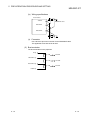
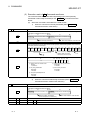
(5)
MELSEC-ST
Cr Command result area
The Cr Command result area stores the results of executing a command to the
head module or each slice module.
The values stored in the Cr Command execution area all turn to 0 when the
Bw.03 Command execution request is turned off.
Refer to Chapter 8 for details of the commands.
(a) Construction of Cr Command result area
The construction of the Cr Command result area is shown below.
Maximum input/output points
2561286432point point point point
mode mode mode mode
b15
b8
Cr.0(15-8) Command execution result
Used
area
Used
area
Used
area
b7
b0
Cr.0(7-0) Start slice No. of execution target
Cr.1 Executed command No.
Used
area
Cr.2 Response data 1
Cr.3 Response data 2
(b) Data stored into Cr Command result area
Data stored into the Cr Command result area are described below.
Cr Command result area
Information
Cr.0 (15-8) Command execution result
Cr.0
Cr.0 (7-0)
3 - 11
Start slice No. of execution target
Description
Stores the command execution result.
Stores the start slice No. of the execution target head
module or slice module.
Cr.1
Executed command No.
Stores the command No. of the executed command.
Cr.2
Response data 1
Stores the response data from the execution target
Cr.3
Response data 2
head module or slice module.
3 - 11
3 SPECIFICATIONS
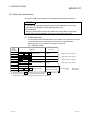
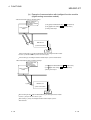
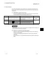
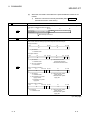
(6)
MELSEC-ST
Wr Word input area
The Wr Word input area stores Wr.n Word input values received from the
intelligent function modules in order of the mounted position.
(a) Construction of Wr Word input area
The construction of the Wr Word input area is shown below.
Maximum input/output points
2561286432point point point point
mode mode mode mode
b0
b15
Wr.00 Intelligent function module word input data 1
Wr.01 Intelligent function module word input data 2
Used
area
Used
area
Used
area
Used
area
Wr.1E Intelligent function module word input data 31
Wr.1F Intelligent function module word input data 32
Wr.32 Intelligent function module word input data 51
Wr.33 Intelligent function module word input data 52
(b) Data size of Wr Word input area
Calculate the data size of the Wr Word input area as described below
according to the mounting conditions of the intelligent function modules.
1) When no intelligent function modules are used
The data size of the Wr Word input area is 0.
3 - 12
3 - 12
3 SPECIFICATIONS
MELSEC-ST
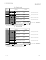
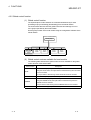
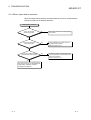
2) When intelligent function modules are used
Reserve the Wr Word input area for as many as the Wr.n Word
input points used by the intelligent function modules.
The Wr Word input area is assigned in order of mounting the
intelligent function modules.
< Wr Word input area assignment example>
1) System example
Mounted module
Start slice No.
2)
Module type
Wr.n Word input
Number of
Occupied Slices points
Wr Word
input area
0
Head module
2
2
Bus refreshing module
1
3
Input module
1
4
Output module
1
5
Power feeding module
1
6
Intelligent function module 1)
2
2 words
Wr.00 Wr.01
8
Intelligent function module 2)
2
2 words
Wr.02 Wr.03
10
Intelligent function module 3)
2
2 words
Wr.04 Wr.05
Wr Word input area assignment example
In the system example in above 1), the Wr Word input area is assigned as shown below.
Wr.00 Intelligent function module 1) word input data 1
Wr.01 Intelligent function module 1) word input data 2
Wr.02 Intelligent function module 2) word input data 1
Wr.03 Intelligent function module 2) word input data 2
Wr.04 Intelligent function module 3) word input data 1
Wr.05 Intelligent function module 3) word input data 2
POINT
For the intelligent function module that can be operated by only the Ww.n Word
output, the number of Wr.n Word input points can be changed to 0 by the slave
parameter setting.
Refer to Section 6.1.4 for the setting in the case where the Wr.n Word input is not
used for the intelligent function module.
3 - 13
3 - 13
3 SPECIFICATIONS
MELSEC-ST
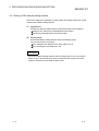
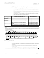
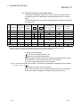
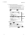
3.2.2 Output data specifications
This section explains the data sizes of output data and the details of each area.
POINT
In this manual, output data addresses (output image addresses on the master
station side) are indicated as offset addresses (word unit).
[Offset address]
Denotes a data position in word units, relative to the first address of the output
image assigned for the MELSEC-ST system on the master station side.
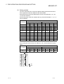
(1) Output data sizes
The output data sizes differ depending on the setting of the maximum I/O points.
The output data sizes for the maximum I/O points are indicated below.
Refer to Section 6.1 for details of the maximum I/O points.
(a) 32-point mode
Offset
address
(Decimal)
+0
+1
+2
+3
+4
+5
to
Application
Data size
Bw.00 to Bw.1F
Bw Bit output area
2 words
Refer to (2) in this section.
Ew.00 to Ew.1F
Ew Error clear area
2 words
Refer to (3) in this section.
Sw.0
Sw System Area
1 words
Cw.0 to Cw.3
Cw Command execution area 4 words
Ww.00 to Ww.33
Ww Word output area
Refer to (4) in this section.
Refer to (5) in this section.
+8
+9
to
Minimum size: 0 words
Maximum size: 52 words
+60
Size variable 1
Refer to (6) in
this section.
1: The data size of the Ww Word output area is a sum total of the Ww Word output
area sizes used by the mounted intelligent function modules.
This data size is 0 when no intelligent function modules are mounted.
3 - 14
3 - 14
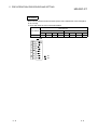
3 SPECIFICATIONS
MELSEC-ST
(b) 64-point mode
Offset
address
(Decimal)
Application
Data size
+0
to
Bw.00 to Bw.3F
Bw Bit output area
4 words
Refer to (2) in this section.
Ew.00 to Ew.3F
Ew Error clear area
4 words
Refer to (3) in this section.
Sw System Area
2 words
+3
+4
to
+7
+8
Sw.0 to Sw.1
+9
+10
to
Cw.0 to Cw.3
Cw Command execution area 4 words
Ww.00 to Ww.33
Ww Word output area
Refer to (4) in this section.
Refer to (5) in this section.
+13
+14
to
Minimum size: 0 words
Maximum size: 52 words
Size variable 1
+65
Refer to (6) in
this section.
1: The data size of the Ww Word output area is a sum total of the Ww Word output
area sizes used by the mounted intelligent function modules.
This data size is 0 when no intelligent function modules are mounted.
(c) 128-point mode
Offset
address
(Decimal)
Application
Data size
+0
to
Bw.00 to Bw.7F
Bw Bit output area
8 words
Refer to (2) in this section.
Ew.00 to Ew.7F
Ew Error clear area
8 words
Refer to (3) in this section.
Sw.0 to Sw.3
Sw System Area
4 words
Cw.0 to Cw.3
Cw Command execution area 4 words
Ww.00 to Ww.33
Ww Word output area
+7
+8
to
+15
+16
to
Refer to (4) in this section.
+19
+20
to
Refer to (5) in this section.
+23
+24
to
Minimum size: 0 words
Maximum size: 52 words
+75
Size variable 1
Refer to (6) in
this section.
1: The data size of the Ww Word output area is a sum total of the Ww Word output
area sizes used by the mounted intelligent function modules.
This data size is 0 when no intelligent function modules are mounted.
3 - 15
3 - 15
3 SPECIFICATIONS
MELSEC-ST
(d) 256-point mode
Offset
address
(Decimal)
Application
Data size
+0
to
Bw.00 to Bw.FF
Bw Bit output area
16 words
Refer to (2) in this section.
Ew.00 to Ew.FF
Ew Error clear area
16 words
Refer to (3) in this section.
Sw.0 to Sw.7
Sw System Area
8 words
Cw.0 to Cw.3
Cw Command execution area 4 words
Ww.00 to Ww.1F
Ww Word output area
+15
+16
to
+31
+32
to
Refer to (4) in this section.
+39
+40
to
Refer to (5) in this section.
+43
+44
to
Minimum size: 0 words
Maximum size: 32 words
+95
Size variable 1
Refer to (6) in
this section.
1: The data size of the Ww Word output area is a sum total of the Ww Word output
area sizes used by the mounted intelligent function modules.
This data size is 0 when no intelligent function modules are mounted.
3 - 16
3 - 16
3 SPECIFICATIONS
MELSEC-ST
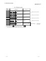
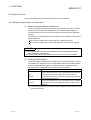
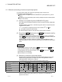
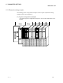
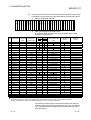
(2)
Bw Bit output area
The Bw Bit output area stores the ON/OFF information of the Bw.n Bit outputs
provided to the head module and slice modules.
Each of the head module and slice modules occupies 2 bits per slice.
The construction of the Bw Bit output area is shown below.
Maximum input/output points
2561286432point point point point
mode mode mode mode
Slice No.
Bw Bit output area
b15
b0
Bw.0F Bw.0E Bw.0D Bw.0C Bw.0B Bw.0A Bw.09
Used
area
Used
area
7
6
5
14
13
22
21
31
30
29
38
37
47
46
45
54
53
63
62
61
70
69
78
77
Bw.68
Bw.78
Bw.88
68
Bw.9F Bw.9E Bw.9D Bw.9C Bw.9B Bw.9A Bw.99
79
Bw.58
60
Bw.8F Bw.8E Bw.8D Bw.8C Bw.8B Bw.8A Bw.89
71
Bw.48
52
Bw.7F Bw.7E Bw.7D Bw.7C Bw.7B Bw.7A Bw.79
Used
area
Bw.38
44
Bw.6F Bw.6E Bw.6D Bw.6C Bw.6B Bw.6A Bw.69
55
Bw.28
36
Bw.5F Bw.5E Bw.5D Bw.5C Bw.5B Bw.5A Bw.59
Bw.06
Bw.05
Bw.16
Bw.15
3
28
Bw.4F Bw.4E Bw.4D Bw.4C Bw.4B Bw.4A Bw.49
39
Bw.17
20
Bw.3F Bw.3E Bw.3D Bw.3C Bw.3B Bw.3A Bw.39
Used
area
Bw.18
12
Bw.2F Bw.2E Bw.2D Bw.2C Bw.2B Bw.2A Bw.29
23
Bw.07
4
Bw.1F Bw.1E Bw.1D Bw.1C Bw.1B Bw.1A Bw.19
15
Bw.08
Bw.98
76
Bw.26
19
Bw.37
Bw.36
27
Bw.47
Bw.46
35
Bw.57
Bw.56
43
Bw.67
Bw.66
51
Bw.77
Bw.76
59
Bw.87
Bw.86
67
Bw.97
Bw.03
Bw.14
Bw.13
2
11
Bw.27
Bw.04
Bw.96
75
Bw.24
18
Bw.35
Bw.34
26
Bw.45
Bw.44
34
Bw.55
Bw.54
42
Bw.65
Bw.64
50
Bw.75
Bw.74
58
Bw.85
Bw.84
66
Bw.95
Bw.01
Bw.12
Bw.11
Bw.22
Bw.21
1
10
Bw.25
Bw.02
Bw.94
74
0
9
Bw.23
Bw.32
25
Bw.43
Bw.42
33
Bw.53
Bw.52
41
Bw.63
Bw.62
49
Bw.73
Bw.72
57
Bw.83
Bw.82
65
Bw.93
Bw.10
8
17
Bw.33
Bw.00
Bw.92
73
Bw.20
16
Bw.31
Bw.30
24
Bw.41
Bw.40
32
Bw.51
Bw.50
40
Bw.61
Bw.60
48
Bw.71
Bw.70
56
Bw.81
Bw.80
64
Bw.91
Bw.90
72
Bw.AF Bw.AE Bw.AD Bw.AC Bw.AB Bw.AA Bw.A9 Bw.A8 Bw.A7 Bw.A6 Bw.A5 Bw.A4 Bw.A3 Bw.A2 Bw.A1 Bw.A0
87
86
85
84
83
82
81
80
Bw.BF Bw.BE Bw.BD Bw.BC Bw.BB Bw.BA Bw.B9 Bw.B8 Bw.B7 Bw.B6 Bw.B5 Bw.B4 Bw.B3 Bw.B2 Bw.B1 Bw.B0
95
94
93
92
91
90
89
88
Bw.CF Bw.CE Bw.CD Bw.CC Bw.CB Bw.CA Bw.C9 Bw.C8 Bw.C7 Bw.C6 Bw.C5 Bw.C4 Bw.C3 Bw.C2 Bw.C1 Bw.C0
103
102
101
100
99
98
97
96
Bw.DF Bw.DE Bw.DD Bw.DC Bw.DB Bw.DA Bw.D9 Bw.D8 Bw.D7 Bw.D6 Bw.D5 Bw.D4 Bw.D3 Bw.D2 Bw.D1 Bw.D0
111
110
109
108
107
106
105
104
Bw.EF Bw.EE Bw.ED Bw.EC Bw.EB Bw.EA Bw.E9 Bw.E8 Bw.E7 Bw.E6 Bw.E5 Bw.E4 Bw.E3 Bw.E2 Bw.E1 Bw.E0
119
118
117
116
Bw.FF Bw.FE Bw.FD Bw.FC Bw.FB Bw.FA Bw.F9
127
3 - 17
126
125
115
Bw.F8 Bw.F7
124
Bw.F6
123
114
Bw.F5
113
Bw.F4 Bw.F3
122
112
Bw.F2 Bw.F1
121
Bw.F0
120
3 - 17
3 SPECIFICATIONS
MELSEC-ST
(3)
Ew Error clear area
The Ew Error clear area stores the error information clear requests of the head
module and slice modules.
This area is used to clear the corresponding error information (turn off the bit) of
the head module or slice module after the error is remedied.
Each of the head module and slice modules occupies 2 bits per slice.
The construction of the Ew Error clear area is shown below.
Maximum input/output points
2561286432point point point point
mode mode mode mode
Slice No.
Ew Error clear area
b15
b0
Ew.0F Ew.0E Ew.0D Ew.0C Ew.0B Ew.0A
Used
area
Used
area
7
6
5
Ew.1F Ew.1E Ew.1D Ew.1C Ew.1B Ew.1A
15
14
13
Ew.2F Ew.2E Ew.2D Ew.2C Ew.2B Ew.2A
23
22
21
Ew.3F Ew.3E Ew.3D Ew.3C Ew.3B Ew.3A
Used
area
31
30
29
Ew.4F Ew.4E Ew.4D Ew.4C Ew.4B Ew.4A
39
38
37
Ew.5F Ew.5E Ew.5D Ew.5C Ew.5B Ew.5A
47
46
45
Ew.6F Ew.6E Ew.6D Ew.6C Ew.6B Ew.6A
55
54
53
Ew.7F Ew.7E Ew.7D Ew.7C Ew.7B Ew.7A
Used
area
63
62
61
Ew.8F Ew.8E Ew.8D Ew.8C Ew.8B Ew.8A
71
70
69
Ew.9F Ew.9E Ew.9D Ew.9C Ew.9B Ew.9A
79
78
Ew.09
77
Ew.08
Ew.07
Ew.18
Ew.17
4
Ew.19
Ew.28
20
Ew.39
Ew.38
28
Ew.49
Ew.48
36
Ew.59
Ew.58
44
Ew.69
Ew.68
52
Ew.79
Ew.78
60
Ew.89
Ew.88
68
Ew.99
Ew.05
Ew.16
Ew.15
3
12
Ew.29
Ew.06
Ew.98
76
Ew.26
19
Ew.37
Ew.36
27
Ew.47
Ew.46
35
Ew.57
Ew.56
43
Ew.67
Ew.66
51
Ew.77
Ew.76
59
Ew.87
Ew.86
67
Ew.97
Ew.03
Ew.14
Ew.13
2
11
Ew.27
Ew.04
Ew.96
75
Ew.24
18
Ew.35
Ew.34
26
Ew.45
Ew.44
34
Ew.55
Ew.54
42
Ew.65
Ew.64
50
Ew.75
Ew.74
58
Ew.85
Ew.84
66
Ew.95
Ew.01
Ew.12
Ew.11
Ew.22
Ew.21
1
10
Ew.25
Ew.02
Ew.94
74
0
9
Ew.23
Ew.32
25
Ew.43
Ew.42
33
Ew.53
Ew.52
41
Ew.63
Ew.62
49
Ew.73
Ew.72
57
Ew.83
Ew.82
65
Ew.93
Ew.10
8
17
Ew.33
Ew.00
Ew.92
73
Ew.20
16
Ew.31
Ew.30
24
Ew.41
Ew.40
32
Ew.51
Ew.50
40
Ew.61
Ew.60
48
Ew.71
Ew.70
56
Ew.81
Ew.80
64
Ew.91
Ew.90
72
Ew.AF Ew.AE Ew.AD Ew.AC Ew.AB Ew.AA Ew.A9 Ew.A8 Ew.A7 Ew.A6 Ew.A5 Ew.A4 Ew.A3 Ew.A2 Ew.A1 Ew.A0
87
86
85
84
83
82
81
80
Ew.BF Ew.BE Ew.BD Ew.BC Ew.BB Ew.BA Ew.B9 Ew.B8 Ew.B7 Ew.B6 Ew.B5 Ew.B4 Ew.B3 Ew.B2 Ew.B1 Ew.B0
95
94
93
92
91
90
89
88
Ew.CF Ew.CE Ew.CD Ew.CC Ew.CB Ew.CA Ew.C9 Ew.C8 Ew.C7 Ew.C6 Ew.C5 Ew.C4 Ew.C3 Ew.C2 Ew.C1 Ew.C0
103
102
101
100
99
98
97
96
Ew.DF Ew.DE Ew.DD Ew.DC Ew.DB Ew.DA Ew.D9 Ew.D8 Ew.D7 Ew.D6 Ew.D5 Ew.D4 Ew.D3 Ew.D2 Ew.D1 Ew.D0
111
110
109
108
107
106
105
104
Ew.EF Ew.EE Ew.ED Ew.EC Ew.EB Ew.EA Ew.E9 Ew.E8 Ew.E7 Ew.E6 Ew.E5 Ew.E4 Ew.E3 Ew.E2 Ew.E1 Ew.E0
119
118
117
116
Ew.FF Ew.FE Ew.FD Ew.FC Ew.FB Ew.FA Ew.F9
127
3 - 18
126
125
115
Ew.F8 Ew.F7
124
Ew.F6
123
114
Ew.F5
113
Ew.F4 Ew.F3
122
112
Ew.F2 Ew.F1
121
Ew.F0
120
3 - 18
3 SPECIFICATIONS
MELSEC-ST
(4)
Sw System area
The Sw System area is used by the head module system.
Store 0 (fixed) into the Sw System area.
The construction of the Sw System area is shown below.
Maximum input/output points
2561286432point point point point
mode mode mode mode
Used
area
Used
area
Used
area
b15
b0
Sw.0 System Area 1
Sw.1 System Area 2
Sw.2 System Area 3
Sw.3 System Area 4
Used
area
Sw.4 System Area 5
Sw.5 System Area 6
Sw.6 System Area 7
Sw.7 System Area 8
3 - 19
3 - 19
3 SPECIFICATIONS
MELSEC-ST
(5)
Cw Command execution area
The Cw Command execution area stores the information of the command to be
executed for the head module or each slice module.
Refer to Chapter 8 for details of the commands.
(a) Construction of Cw Command execution area
The construction of the Cw Command execution area is shown below.
Maximum input/output points
256point
mode
128point
mode
64point
mode
32point
mode
b15
b0
Cw.0 Start slice No. of execution target
Used
area
Used
area
Used
area
Cw.1 Command No. to be executed
Used
area
Cw.2 Argument 1
Cw.3 Argument 2
(b) Data stored into Cw Command execution area
Data stored into the Cw Command execution area are described below.
Cw Command execution area
3 - 20
Information
Cw.0
Start slice No. of execution target
Cw.1
Command No. to be executed
Cw.2
Argument 1
Cw.3
Argument 2
Description
Stores the start slice No. of the execution target
head module or slice module.
Stores the command No. of the command to be
executed.
Stores the argument used in the command.
3 - 20
3 SPECIFICATIONS
MELSEC-ST
(6)
Ww Word output area
Stores the Ww.n Word output values of the intelligent function modules in order
of the mounted position.
(a) Construction of Ww Word output area
The construction of the Ww Word output area is shown below.
Maximum input/output points
256point
mode
128point
mode
64point
mode
32point
mode
b0
b15
Ww.00 Intelligent function module word input data 1
Ww.01 Intelligent function module word input data 2
Used
area
Used
area
Used
area
Used
area
Ww.1E Intelligent function module word input data 31
Ww.1F Intelligent function module word input data 32
Ww.32 Intelligent function module word input data 51
Ww.33 Intelligent function module word input data 52
(b) Data size of Ww Word output area
Calculate the data size of the Ww Word output area as described below
according to the mounting conditions of the intelligent function modules.
1) When no intelligent function modules are used
The data size of the Ww Word output area is 0.
3 - 21
3 - 21
3 SPECIFICATIONS
MELSEC-ST
2) When intelligent function modules are used
Reserve the Ww Word output area for as many as the Ww.n Word
output points used by the intelligent function modules.
The Ww Word output area is assigned in order of mounting the
intelligent function modules.
< Ww Word output area assignment example>
1) System example
Mounted module
Start slice No.
Module type
2)
Number of
Occupied Slices
Ww.n Word
output points
Ww Word
output area
0
Head module
2
2
Bus refreshing module
1
3
Input module
1
4
Output module
1
5
Power feeding module
1
6
Intelligent function module 1)
2
2 words
Ww.00 Ww.01
8
Intelligent function module 2)
2
2 words
Ww.02 Ww.03
10
Intelligent function module 3)
2
2 words
Ww.04 Ww.05
Ww Word output area assignment example
In the system example in above 1), the Ww Word output area is assigned as shown below.
Ww.00 Intelligent function module 1) word output data 1
Ww.01 Intelligent function module 1) word output data 2
Ww.02 Intelligent function module 2) word output data 1
Ww.03 Intelligent function module 2) word output data 2
Ww.04 Intelligent function module 3) word output data 1
Ww.05 Intelligent function module 3) word output data 2
POINT
For the intelligent function module that can be operated by only the Wr.n Word
input, the number of Ww.n Word output points can be changed to 0 by the slave
parameter setting.
Refer to Section 6.1.4 for the setting in the case where the Ww.n Word output is
not used for the intelligent function module.
3 - 22
3 - 22
3 SPECIFICATIONS
MELSEC-ST
3.2.3 I/O data used by head module
This section explains the areas used for I/O data by the head module and their
applications and information.
REMARK
For the applications of the areas assigned to each slice module, refer to the manual
of each slice module.
(1) Input data
(a) Br Bit input area
The following table describes the applications of the Br Bit input area used
by the head module.
The head module uses the first 4 bits ( Br.00 to Br.03 ) of the Br Bit input
area.
Br.n Bit input
Module READY
Br.00
Stores the information on whether the head
module can communicate with the master
station.
Forced output test mode
Br.01
Stores the information on whether the head
module is in the forced output test mode.
Online module change (OMC)
Br.02
Stores the information on whether the
MELSEC-ST system is ready for online module
change.
Command execution
Br.03
Br.n Bit input status
Application
Stores the information on the execution status
of the command requested in the Cw
Command execution area.
0: MELSEC-ST system being prepared or error
occurred
1: MELSEC-ST system ready
0: Waiting for forced output test mode to be
executed
1: Forced output test mode being executed
0: Waiting for online module change to be
executed
1: Online module change being executed
0: Command being executed or waiting for
command request
1: Command execution
0: OFF, 1: ON
3 - 23
3 - 23
3 SPECIFICATIONS
MELSEC-ST
(b)
Er Error information area
The following table indicates the information of the Er Error information
area used by the head module and the error codes corresponding to the
error information.
The head module uses the first 4 bits ( Er.00 to Er.03 ) of the Er Error
information area.
Read the error code from the head module by any of the following methods.
(Refer to Section 9.2.1)
Extended diagnostic information notification function
Command
GX Configurator-ST
The stored error information can be cleared by turning ON the Ew.00
Error Clear Request.
Er.n Error information
Information
Error code
Er.03
Er.02
Er.01
Er.00
0
0
0
0
Normal
0
0
0
1
FDL address change error
F201H
1
0
1
1
User parameter setting error
F203H
1
1
0
0
Module error
F200H
1
1
0
1
1
1
1
0
Parameter read error
(Online module change)
Replaced module error
(Online module change)
1
C101H to C13FH
C201H to C23FH
0: OFF, 1: ON
1: Refer to Section 9.2.2 for the error codes.
(c)
Mr Module status area
The following table indicates the information of the Mr Module status area
used by the head module.
The head module uses the first 2 bits ( Mr.0 to Mr.1 ) of the Mr Module
status area.
Mr.n Module status
Information
Description
Mr.1
Mr.0
0
0
Hardware fault
A hardware fault occurred in the head module.
1
1
Normal
The head module is operating normally.
0: OFF, 1: ON
3 - 24
3 - 24
3 SPECIFICATIONS
MELSEC-ST
(2) Output data
(a) Bw Bit output area
The following table describes the applications of the Bw Bit output area
used by the head module.
The head module uses the first 4 bits ( Bw.00 to Bw.03 ) of the Bw Bit
output area.
Bw.n Bit output
Bw.n Bit output status
Application
Bw.00
System area
Bw.01
0 (Fixed)
Use prohibited
Bw.02
Command request
Bw.03
The command sent from the master
station is requested to be executed.
0: Command not requested
1: Command requested
0: OFF, 1: ON
(b)
Ew Error clear area
1) Ew Error clear area of each slice module
The error clear request bit of each slice module is the first bit of the
assigned Ew Error clear area.
<Example>
When the number of occupied slices is "4" and the start slice No. is "66", the error clear request bit is Ew.84
Ew.8B
Ew.8A
Ew.89
Ew.88
Ew.87
Ew.86
Ew.85
Ew.84
Error
clear
request
System Area (Use prohibited)
69
68
2)
67
66
Ew.n Error clear
Application
Slice No.
Ew Error clear area of head module
The following table indicates the information of the Ew Error clear
area used by the head module.
The head module uses the first 4 bits ( Ew.00 to Ew.03 ) of the Ew
Error clear area.
Ew.n Error clear
Application
Error clear request
Ew.00
Stores the error information clear
request of the head module.
Ew.n Error clear status
0: Error clear not requested
1: Error clear requested
Ew.01
Ew.02
Ew.03
System area
Use prohibited
0 (Fixed)
0: OFF, 1: ON
3 - 25
3 - 25
3 SPECIFICATIONS
MELSEC-ST
3) Precautions for using the Ew.n error clear
If an error cause has not yet been eliminated when the error clear
request bit is turned off, the error information is set to the Er Error
information area again.
(While the Ew.n Error clear is on, the corresponding bits of the Er
Error information area all turn off.)
ON
OFF
Ew.n Error clear
Er Error Information
Area
All bits off
ON
OFF
Error information set
All bits off
Error information set
All bits off
Abnormal (error occurred)
Status of each module Normal
Error
occurrence
3 - 26
As action to remove error factor is
not completed, error information
is set to Er Error Information
Area again.
Error removed
3 - 26
3 SPECIFICATIONS
MELSEC-ST
3.3 Head Module Processing Time
This section explains the processing time of the head module in the MELSEC-ST
system.
Communication processings between the master station and MELSEC-ST system are
outlined below.
(1) Input data processing outline
How input data from an external device is sent to the master station is shown
below.
ON
Class 1 master
station
PROFIBUS-DP
Head module
Refer to the manual
of the master station
for the master station
processing time.
Bus cycle time
ST bus cycle time
(Refer to Section 3.3.1.)
Slice module
Input status
External device
ON
Input transmission delay time (refer to Section 3.3.2)
(2) Output data processing outline
How output data from the master station is output to an external device is shown
below.
Class 1 master
station
PROFIBUS-DP
Head module
Slice module
ON
Refer to the master
station manual for
the master station
processing time.
Bus cycle time
ST bus cycle time
(Refer to Section 3.3.1.)
Output status
External device
ON
Output transmission delay time (refer to Section 3.3.3)
3 - 27
3 - 27
3 SPECIFICATIONS
MELSEC-ST
3.3.1 ST bus cycle time
ST bus cycle time is the time required for the head module to refresh input or output
data for the slice modules.
This section explains the ST bus cycle time expression and processing time example.
(1) ST bus cycle time expression
The expression for calculating the ST bus cycle time is given below.
*1
ST bus cycle time [ s] = {24 ( 1) + 2)) }
*2
+ (157 number of mounted intelligent function modules) + (internal processing time )
1: Calculate 1) and 2) by the following expressions.
When there are slice modules whose occupied I/O points are equal to or
less than 4 points
1) = number of mounted slice modules
When there are slice modules whose occupied I/O points are greater than
4 points
2) = (number of occupied I/O points / 4) number of mounted slice
modules
<Example>
When there are three slice modules having 2 occupied I/O points, two
slice modules having 4 points, and three slice modules having 16 points
1) + 2) = 5 + (16 / 4) 3 = 17
2: The internal processing time changes depending on the maximum
input/output points.
32-point mode: 385 s
64-point mode: 400 s
128-point mode: 430 s
256-point mode: 490 s
3 - 28
3 - 28
3 SPECIFICATIONS
MELSEC-ST
(2) Processing time example
The following system configuration example is used to explain a processing time
example of ST bus cycle time.
(The following table uses the maximum input/output points sheet provided in
Appendix 2.1.)
No.0
No.1
No.2
No.3
No.4
No.5
No.6
.
No.
Module name
Number of
Occupied I/O
Points
Start Slice No.
(Number of
occupied slices)
0
ST1H-PB
4
0(2)
1
ST1PSD
2
2(1)
2
ST1X2-DE1
2
3(1)
3
ST1Y2-TE2
2
4
ST1PDD
2
Wr.n
Ww.n
5V DC Internal
Current
Consumption
(Total)
24V DC Current
(Total)
0.530A(0.530A)
0A(0A)
Slot Width
(Total)
25.2mm(25.2mm)
0.085A(0.615A)
1
4(1)
0.090A(0705A)
1
5(1)
0.060A(0.765A)
12.6mm(37.8mm)
12.6mm(50.4mm)
12.6mm(63.0mm)
5
ST1AD2-V
4
6(2)
2
2
0.110A(0.875A)
1
12.6mm(75.6mm)
6
ST1DA2-V
4
8(2)
2
2
0.095A(0.970A)
1
12.6mm(88.2mm)
4
4
Total
20
1: The 24V DC current changes depending on the external device connected to each slice module.
Confirm the current consumption of the external device connected to each slice module, and calculate the total value.
Refer to the MELSEC-ST System User's Manual for details of current consumption calculation.
Number of mounted intelligent function modules: 2
Maximum input/output points: 32-point mode
ST bus cycle time = {24
3 - 29
(6 + 0)} + (157
2) + 385
843 [ s]
3 - 29
3 SPECIFICATIONS
MELSEC-ST
3.3.2 Input transmission delay time
This section explains the time required from when the slice module receives input data
from the external device until it outputs that data onto the PROFIBUS-DP line.
(1) Average delay time
Average input transmission delay time is indicated below.
Input transmission delay time = 1) + (1.5
ST bus cycle time)
+ (0.5
bus cycle time)
Input module response time
1): For input module
For intelligent function module
Intelligent function module processing time
For details, refer to the MELSEC-ST System User's Manual or intelligent
function module manual.
ST bus cycle time: Refer to Section 3.3.1.
Bus cycle time: Refer to the manual of the master station.
(2) Maximum delay time
Maximum input transmission delay time is indicated below.
ST bus cycle time)
+ (1.0 bus cycle time)
Input module response time
1): For input module
For intelligent function module
Intelligent function module processing time
For details, refer to the MELSEC-ST System User's Manual or intelligent
function module manual.
ST bus cycle time: Refer to Section 3.3.1.
Bus cycle time: Refer to the manual of the master station.
Input transmission delay time = 1) + (2.0
3 - 30
3 - 30
3 SPECIFICATIONS
MELSEC-ST
3.3.3 Output transmission delay time
This section explains the time required from when the head module receives output
data from the master station until the slice module outputs data to the external device.
(1) Average delay time
Average output transmission delay time is indicated below.
Output transmission delay time = (1.0
ST bus cycle time) + 1)
ST bus cycle time: Refer to Section 3.3.1.
Output module response time
1): For output module
For intelligent function module
Intelligent function module processing time
For details, refer to the MELSEC-ST System User's Manual or intelligent
function module manual.
(2) Maximum delay time
Maximum output transmission delay time is indicated below.
Output transmission delay time = (1.5
ST bus cycle time) + 1)
ST bus cycle time: Refer to Section 3.3.1.
1): For output module
Output module response time
For intelligent function module
Intelligent function module processing time
For details, refer to the MELSEC-ST System User's Manual or intelligent
function module manual.
3 - 31
3 - 31
4 FUNCTIONS
MELSEC-ST
4 FUNCTIONS
This chapter explains the head module functions.
4.1 Function List
The head module functions are listed below.
(1) Network functions
The following table describes the head module functions used in the PROFIBUSDP network.
To use the following functions, set the user parameters on the configuration
software of the master station.
Function name
I/O data communication
function
Global control function
Extended diagnostic
information notification
function
Description
Communicates I/O data with the master station.
Controls the inputs/outputs of slave stations in the specified group
simultaneously by multicasting (broadcasting) from the master station.
Notifies the master station of head module and slice module errors as
extended diagnostic information.
Reference section
Section 4.2.1
Section 4.2.2
Section 4.2.3
Swaps the high and low bytes in word units when input or output data are sent
to or received from the master station or when extended diagnostic information
Swap function
is sent to the master station.
When the master station handles the high and low bytes of word data in
Section 4.2.4
reverse to the head module, using this function allows data communication
without creating a high/low byte swapping program.
I/O data consistency
Prevents data inconsistency between the communication data of PROFIBUS-
function
DP and the I/O data of the head module.
4-1
Section 4.2.5
4-1
4
4 FUNCTIONS
MELSEC-ST
(2) Control functions
The following table describes the functions used by the head module to control
the slice modules.
Function name
1)
Setting of output
Sets whether the refresh of data output to the other normally
status at module
operating output modules and intelligent function modules will be
error
stopped or continued when an error occurs in a slice module.
Information
Monitors various information of the head module and slice
monitor
modules.
Status monitor
4
Operation method
Description
2)
The I/O modules and intelligent function modules can be
replaced without stopping the MELSEC-ST system.
Section 4.3.2
Section 4.4
Forced output test Forcibly outputs the Bw.n Bit Output, Ew.n Error Clear and
Ww.n Word Output of the head module and each slice module.
function
Intelligent function
module parameter
read/write
1
Reads or writes parameters from or to the ROM or RAM of the
2
intelligent function module.
Head module
Reads the MELSEC-ST system parameters sent from the master
parameter read
station to the head module.
network parameter
read
Section 4.3.3
Section 5.3.2
Head module reset Resets the MELSEC-ST system.
PROFIBUS-DP
section
1
history, etc. of the head module.
change
4)
Section 4.3.1
Monitors the operating statuses of the slice modules and the error
Online module
3)
Reference
Reads the PROFIBUS-DP network parameters sent from the
master station to the head module.
1
1
PROFIBUS-DP
Reads the input data sent from the head module to the master
communication
station and the output data sent from the master station to the
data read
head module.
Self-diagnostics
Runs a hardware test on the single head module.
Section 5.4
Executes a command requested by the master station.
Chapter 8
Command
execution
: Can be executed,
1
: Cannot be executed
1) Use the configuration software of the master station to set the user parameter.
2) Use the button or switch of the head module to perform operation.
3) Execute a command from the master station.
4) Use GX Configurator-ST to perform operation.
1: For the operation of GX Configurator-ST, refer to the GX Configurator-ST Operating Manual.
2: Setting from the configuration software of the master station allows the user parameters to be written to only the RAM
of the intelligent function module.
4-2
4-2
4 FUNCTIONS
MELSEC-ST
4.2 Network Functions
This section explains the head module functions used in the PROFIBUS-DP network.
4.2.1 I/O data communication function
(1) I/O data communication function
I/O data can be communicated with the Class 1 master station (master station
that makes cyclic data communication with slave stations) of PROFIBUS-DP.
The head module can exchange up to 304-byte data in total with the master
station: up to 152-byte input data (head module master station) and up to 152byte output data (master station head module).
Class 1 master
station
Input image
Output image
Head module
Input data
Slice
module
Input
status
Slice
module
Input
status
Output data
Output
status
Output
status
(2) I/O data size
The size of I/O data communicated with the master station changes depending
on the maximum input/output points.
Refer to Chapter 6 for the maximum input/output points.
Refer to Section 3.2.1 and Section 3.2.2 for the I/O data size for the maximum
input/output points.
4-3
4-3
4 FUNCTIONS
MELSEC-ST
(3) I/O status when the CPU stop error has occurred in master station
If an error (PLC CPU stop error) has occurred in a master station, the I/O status
of the master station varies with the master station used.
The following table shows the I/O status when an error has occurred in a master
station for each model.
Maser station
model
Master station I/O status
Input data
Output data
Communication status
The input data sent from The output data sent to
QJ71PB92D
AJ71PB92D,
A1SJ71PB92D
Master stations
other than above
4-4
slave stations are
slave stations when the Continued
refreshed.
CPU stops are held.
The input data sent from
slave stations when the Cleared
Stopped
CPU stops are held.
Refer to the manual for the master station
4-4
4 FUNCTIONS
MELSEC-ST
4.2.2 Global control function
(1) Global control function
The inputs/outputs of slave stations are controlled simultaneously for each
specified group by multicasting (broadcasting) from the master station.
The head module that executes the global control function belongs to one or
more groups specified by the master station.
Set the group number of the head module using the configuration software of the
master station.
Class 1 master station
Sent to group 1
MELSECST slave
station
Slave
station
Slave
station
Slave
station
Group 1
Slave
station
Group 2
(2) Global control services available for head module
The following table describes the global control services available for the global
control function of the head module.
Service name
Description
Starts the SYNC (output synchronization) mode.
SYNC
During the SYNC mode, the output status is refreshed every time the SYNC
service is received.
The output status is held as long as the SYNC service is not received.
UNSYNC
Ends the SYNC (output synchronization) mode.
Starts the FREEZE (input synchronization) mode.
FREEZE
During the FREEZE mode, the input status is refreshed every time the
FREEZE service is received.
The input status is held as long as the FREEZE service is not received.
UNFREEZE
4-5
Ends the FREEZE (input synchronization) mode.
4-5
4 FUNCTIONS
MELSEC-ST
(3) Outline of service operations
The following shows the outline of the SYNC and UNSYNC services and
FREEZE and UNFREEZE services.
(a) When receiving SYNC and UNSYNC services
1) Before receiving SYNC service
Class 1 master
station
Head module
Slice
module
Input data
Input data
Input
status
Output data
Output data
Output
status
station
Head module
Slice
module
Input data
Input data
Input
status
2) After receiving SYNC service
Class 1 master SYNC service
When receiving the SYNC service, the head
module enters the SYNC mode, and stops refresh
from its output receiving area to the output status
area of the slice module.
During the SYNC mode, the SYN. LED of the head
module is on.
Output data
3) After receiving UNSYNC service
Class 1 master UNSYNC service
Output data
Output
status
Even during the SYNC mode, refresh from the input
status area to the input sending area is executed
continuously.
station
Head module
Slice
module
Input data
Input data
Input
status
Output data
4-6
When the SYNC service is received during the
SYNC mode, refresh to the output status area is
performed only once.
Output data
Output
status
When receiving the UNSYNC service, the head
module ends the SYNC mode and resumes refresh
from its output receiving area to the output status
area of the slice module.
When the UNSYNC service is received and the
SYNC mode is ended, the SYN. LED of the head
module turns off.
4-6
4 FUNCTIONS
MELSEC-ST
(b) When receiving FREEZE and UNFREEZE services
1) Before receiving FREEZE service
Class 1 master
station
Head module
Slice
module
Input data
Input data
Input
status
Output data
Output data
Output
status
Head module
Slice
module
Input data
Input data
Input
status
Output data
Output data
Output
status
2) After receiving FREEZE service
FREEZE service
Class 1 master
station
When receiving the FREEZE service, the head
module enters the FREEZE mode, and stops
refresh from the input status area of the slice
module to the input sending area of the head
module.
During the FREEZE mode, the FRE. LED of the
head module is on.
When the FREEZE service is received during the
FREEZE mode, refresh to the input sending area
is performed only once.
Even during the FREEZE mode, refresh from the
output receiving data to the output status area is
executed continuously.
3) After receiving UNFREEZE service
Class 1 master UNFREEZE service
station
Head module
Slice
module
Input data
Input data
Input
status
Output data
Output data
Output
status
When receiving the UNFREEZE service, the head
module ends the FREEZE mode, and resumes
refresh from the input status area of the slice
module to the input sending area area of the head
module.
When the UNFREEZE service is received and the
FREEZE mode is ended, the FRE. LED of the
head module turns off.
(4) Group selection
There are a total of 8 groups from 1 to 8.
The head module is allowed to belong to any of the 8 groups. (Specify the group
using the configuration software of the master station.)
4-7
4-7
4 FUNCTIONS
MELSEC-ST
4.2.3 Extended diagnostic information notification function
(1) Extended diagnostic information notification function
When errors occur in the head module and/or slice modules, this function can
notify the master station of the errors of up to 2 modules in chronological order.
When the head module has notified the master station of extended diagnostic
information, the DIA LED of the head module is on.
When the head module and/or slice modules return to normal, the master station
is notified and the DIA LED of the head module turns off.
Class 1 master station
Master station is notified of error as
extended diagnostic information.
Head module
Slice
module
1)
Slice
module
2)
Error
occurred!
(2) Setting of extended diagnostic information notification function
The extended diagnostic information notification function defaults to "Enable
(Notified)".
When the master station is not notified of extended diagnostic information, the
extended diagnostic information notification function setting must be changed on
the configuration software of the master station.
Use the "Ext_Diag information" user parameter to set this function.
The setting items of Ext_Diag information are as follows.
Item
Enable
Notifies the master station of head module and/or slice module
(Default)
errors as extended diagnostic information.
Disable
4-8
Description
If errors occur in the head module and/or slice modules, does not
notify the master station of extended diagnostic information.
4-8
4 FUNCTIONS
MELSEC-ST
(3) Extended diagnostic information data
(a) Data sent to master station
When the extended diagnostic information notification function is set to
"Enable (notified)", the head module sends the following data to the
extended diagnostic information area of the master station.
Refer to the manual of the master station for the extended diagnostic
information area of the master station.
Offset address
Name
(Unit: Word)
+ 0 Head module error code
+1
Error slice No.
First module
+2
Detail error code 1
+ 3 Error slice module
Detail error code 2
+ 4 information
Error slice No.
+5
1
Second module
+6
Detail error code 1
Detail error code 2
1: The error slice module information of two modules is stored in chronological
order.
REMARK
Depending on the master station, the high and low bytes of the extended diagnostic
information data sent from the head module may be reverse to those of the
extended diagnostic information area of the master station.
In that case, use the swap function of the head module.
Refer to Section 4.2.4 for details.
(b) Details of sending data area
1) Head module error code area
Stores an error code corresponding to the error that occurred in the
head module.
Refer to Section 9.2.2 for the error codes of the head module.
4-9
4-9
4 FUNCTIONS
MELSEC-ST
2) Error slice module information area
Stores the information of up to 2 error slice modules in chronological
order.
The details of the error slice module information area are described
below.
Name
Description
Stores the start slice No. of the slice module where an
Error slice No.
error occurred. (Stores 0000H when no error has
occurred.)
Detail error code 1
Detail error code 2
Stores the error code
1
2
of the slice module where
an error occurred. (Stores 0000H when no error has
occurred.)
1: The error code stored into this area is the same as the value stored into
the Cr Command result area when the command (0101H) is executed.
For error codes of the intelligent function module, refer to the manual of
the intelligent function module.
When an error occurred in the power distribution module or I/O module, an
error code of the head module is stored.
2: If a hardware or similar fault occurs in the slice module, FFFFH is stored
into Detail error code 1.
In that case, please consult your local Mitsubishi representative,
explaining a detailed description of the problem.
REMARK
When the master station is not notified of the extended diagnostic information,
confirm the error information in the Er Error information area of each module, and
execute the command (0101H) to read the error code.
4 - 10
4 - 10
4 FUNCTIONS
MELSEC-ST
4.2.4 Swap function
(1) Swap function
The high and low bytes are swapped in word units when input or output data are
sent to or received from the master station or when extended diagnostic
information is sent to the master station.
When the relevant user parameter of the head module is set to "Enable
(swapped)", the following processing is executed.
I/O data ....The data stored in the input sending area are sent to the master
station after their high and low bytes have been swapped.
The data received from the master station are stored into the output
receiving area after their high and low bytes have been swapped.
Extended diagnostic information .... The extended diagnostic information data
are sent to the master station after their
high and low bytes have been swapped.
Use this function when the used master station handles the high and low bytes of
word data in reverse to those of the head module.
Data can be swapped for communication without the need for creating a program
for swapping the high and low bytes.
Head module
Input sending area
Class 1 master station
Input image
Data 1
(L)
Data 1
(H)
Data 1
(L)
Data 1
(H)
Data 2
(L)
Data 2
(H)
Data 2
(L)
Data 2
(H)
Output data
Output image
Data 3
(L)
Data 3
(H)
Data 3
(L)
Data 3
(H)
Data 4
(L)
Data 4
(H)
Data 4
(L)
Data 4
(H)
Swap processing
Input data
Data 1
(H)
Data 1
(L)
Data 2
(H)
Data 2
(L)
Output receiving area
Data 3
(H)
Data 3
(L)
Data 4
(H)
Data 4
(L)
PROFIBUS-DP data communication
H: High byte, L: Low byte
(2) Setting and operation outline for I/O data swapping
The following describes the setting for I/O data swapping, the swap function
setting by the master station type, and operation outline.
(a) Setting at master station
To swap I/O data, swap setting must be made on the configuration software
of the master station.
Make the swap setting of I/O data using the "Swap of input/output data"
user parameter.
The setting items of Swap of input/output data are as follows.
Item
Enable
Disable
(Default)
4 - 11
Description
The high and low bytes are swapped in word unit when I/O
data are sent or received.
Swap is not executed when I/O data are sent or received.
4 - 11
4 FUNCTIONS
MELSEC-ST
(b) Swap function setting by master station type
The swap function setting changes depending on the master station type as
described below.
Master station type
Swap function setting of head module
AJ71PB92D, A1SJ71PB92D
Disable (Not swapped)
When swap is not executed on
QJ71PB92D
master station side (Default setting)
When swap is not executed on
master station side
Disable (Not swapped)
Enable (Swapped)
Set according to the specifications of
Other master station
the master station
(c) Operation outline
When the AJ71PB92D, A1SJ71PB92D or QJ71PB92D is used as the
master station, the operation outline is as shown below.
1) When the master station is the AJ71PB92D,
A1SJ71PB92D or QJ71PB92D (not swapped)
Class 1 master station
Head module
Input sending area
Input data
Input image
Data 1
(H)
Data 1
(L)
Data 1
(H)
Data 1
(L)
Data 1
(H)
Data 1
(L)
Data 2
(H)
Data 2
(L)
Data 2
(H)
Data 2
(L)
Data 2
(H)
Data 2
(L)
Output receiving area
Output data
Output image
Data 3
(H)
Data 3
(L)
Data 3
(H)
Data 3
(L)
Data 3
(H)
Data 3
(L)
Data 4
(H)
Data 4
(L)
Data 4
(H)
Data 4
(L)
Data 4
(H)
Data 4
(L)
PROFIBUS-DP data communication
H: High byte, L: Low byte
2) When the master station is the QJ71PB92D (swapped)
Head module
Input sending area
Class 1 master station
Output image
Data 1
(L)
Data 2
(H)
Data 2
(L)
Data 3
(H)
Data 3
(L)
Data 4
(H)
Data 4
(L)
Data 1
(L)
Data 1
(H)
Data 2
(L)
Data 2
(H)
Output data
Data 3
(L)
Data 3
(H)
Data 4
(L)
Data 4
(H)
Swap processing
Input image
Data 1
(H)
Swap processing
Input data
Data 1
(H)
Data 1
(L)
Data 2
(H)
Data 2
(L)
Output receiving area
Data 3
(H)
Data 3
(L)
Data 4
(H)
Data 4
(L)
PROFIBUS-DP data communication
H: High byte, L: Low byte
4 - 12
4 - 12
4 FUNCTIONS
MELSEC-ST
(3) Setting and operation outline for extended diagnostic information
swapping
The following describes the setting for extended diagnostic information swapping
and the data construction of the extended diagnostic information.
(a) Setting at master station
To swap extended diagnostic information, swap setting must be made on
the configuration software of the master station.
Make the swap setting of extended diagnostic information using the "Swap
of Ext_Diag information" user parameter.
The setting items of Swap of Ext_Diag information are as follows.
Item
Enable
Description
The high and low bytes are swapped in word units when
extended diagnostic information is sent.
Disable
Swap is not executed when extended diagnostic information
(Default)
is sent.
(b) Swap function setting by master station type
The swap function setting changes depending on the master station type as
described below.
Master station type
Swap function setting of head module
AJ71PB92D, A1SJ71PB92D,
QJ71PB92D
Other master station
Disable (Not swapped)
Set according to the specifications of the master
station
(c) Data construction of extended diagnostic information
The data construction of extended diagnostic information is shown below.
<When "Disable (not swapped)" is selected>
Offset address
(Unit: Word)
+0
+1
+2
+3
+4
+5
+6
Extended diagnostic
information
Head module error code
H
L
First module error slice No.
L
H
First module detail error code 1
L
H
First module detail error code 2
H
L
Second module error slice No.
H
L
Second module detail error code 1
H
L
Second module detail error code 2
L
H
<When "Enable (swapped)" is selected>
Offset address
(Unit: Word)
+0
+1
+2
+3
+4
+5
+6
Extended diagnostic
information
Head module error code
L
H
First module error slice No.
L
H
First module detail error code 1
L
H
First module detail error code 2
L
H
Second module error slice No.
L
H
Second module detail error code 1
L
H
Second module detail error code 2
L
H
H: High byte, L: Low byte
4 - 13
4 - 13
4 FUNCTIONS
MELSEC-ST
4.2.5 I/O data consistency function
(1) I/O data consistency function
This function prevents data inconsistency between the communication data of
PROFIBUS-DP and the I/O data of the head module.
When using either or both of the following items in the MELSEC-ST system,
make the data consistency function setting.
When intelligent function modules are used in the MELSEC-ST system
When the master station requests the MELSEC-ST system to send a command
(2) Input data consistency
The input data to be sent from the head module to the master station are
processed in the head module to prevent inconsistency.
No setting is required for input data consistency.
(3) Output data consistency
For the output data sent from the master station to the head module, the
consistency function setting must be made using the configuration software of
the master station.
(a) Setting at master station
Use the "Consistency function" user parameter to set the consistency
function.
The setting items of Consistency function are as follows.
Refer to (3) (b) in this section for the selection of the consistency function.
Item
Description
Enable
(Default)
Consistency processing of the head module and intelligent
function module control operations is executed in the head
module and intelligent function modules.
Disable
Consistency processing of the head module and intelligent
function module control operations is not executed. 1
1: When the consistency function is set to "Disable", the time required for the
command request to the head module and the control operation of the
intelligent function module is shortened by one bus cycle time.
(b) Consistency function
Select Modules of the head module and the output data consistency
function of the master station must be considered to set the consistency
function.
A consistency function selection table is given below.
Select Modules of head module
Master station specifications
ST1H-PB **pts.-whole consistent
When master station can prevent inconsistency of
whole output data 1
Disable
When master station cannot prevent inconsistency
of whole output data 1
Enable
ST1H-PB **pts.-word consistent
Enable
1: The size of output data changes depending on the maximum input/output points of the head module.
Refer to Section 3.2.2 for the output data size.
4 - 14
4 - 14
4 FUNCTIONS
MELSEC-ST
(4) Difference between operations depending on setting
The following shows a difference between head module and intelligent function
module operations depending on the setting.
(a) Example of command execution
<When head module setting is "Enable">
Master station that
cannot prevent
inconsistency of whole
output data
1) Bw.03 Command request
2) Command execution data ( Cw Command execution area)
Class 1 master
station
3) Command result data ( Cr Command result area)
4) Br.03 Command execution
3)+4)
2)
MELSEC-ST
1)
system slave station
When a command request is received by the head module
After receiving 1), the head module accepts 2) in the next ST
bus cycle and executes the command.
When a command result is sent from the head module
The head module sends 3) and 4) in the same ST bus cycle.
<When head module setting is "Disable">
Master station that
can prevent
inconsistency of
whole output data
1) Bw.03 Command request
2) Command execution data ( Cw Command execution area)
Class 1 master
station
3) Command result data ( Cr Command result area)
4) Br.03 Command execution
3)+4)
1)+2)
MELSEC-ST
system slave station
When a command request is received by the head module
The head module accepts 1) and 2) in the same ST bus cycle
and executes the command.
When a command result is sent from the head module
The head module sends 3) and 4) in the same ST bus cycle.
4 - 15
4 - 15
4 FUNCTIONS
MELSEC-ST
(b) Example of communication with intelligent function module
(digital-analog conversion module)
<When head module setting is "Enable (valid)">
Master station that
cannot prevent
inconsistency of whole
output data
Class 1 master
station
1) CH
output enable/disable flag ( Bw Bit output area)
2) CH
digital value setting ( Ww Word output area)
3) Analog value output
2)
MELSEC-ST
1)
system slave station
3)
External
device
When receiving the CH output enable/disable flag, the intelligent function module
receives 1) and then receives 2) in the next ST bus cycle.
After receiving 2), the intelligent function module outputs 3) to the external device.
<When head module setting is "Disable (invalid)">
Master station that
can prevent
inconsistency of
whole output data
Class 1 master
station
1)+2)
1) CH
output enable/disable flag ( Bw Bit output area)
2) CH
digital value setting ( Ww Word output area)
3) Analog value output
MELSEC-ST
system slave station
3)
External
device
When receiving the CH output enable/disable flag, the intelligent function module
receives 1) and 2) in the same ST bus cycle.
After receiving 1) and 2), the intelligent function module outputs 3) to the
external device.
4 - 16
4 - 16
4 FUNCTIONS
MELSEC-ST
4.3 Control Functions
This section explains the functions used to control each slice module.
4.3.1 Setting of output status at module error
(1) Setting of output status at module error
This is set to determine whether the refresh of output data to the other normallyoperating output modules and intelligent function modules will be stopped or
continued when an error occurs in a slice module (except the power distribution
module).
This function is executed when the head module or slice module is in either of the
following statuses.
When the slice module fails to respond due to a hardware fault, etc.
When the slice module is removed forcibly while the external power supply is
on
POINT
(1) The output status of the slice module where an error occurred changes to the
status set with its user parameter.
(2) The input data are kept refreshed even if an error occurs in the slice module.
(2) Setting at master station
To use the Setting of output status at module error, the output status in the event
of a module error must be set on the configuration software of the master station.
Use the "Output status at module error" user parameter to make this setting.
The setting items of Output status at module error are as follows.
Item
Description
When a slice module error occurs, the output data of the normally
Stop
operating output module and intelligent function module are
(Default)
brought into the statuses preset by the user parameters
1 of the
corresponding slice modules.
When a slice module error occurs, the output data of the normally
Continue
operating output module and intelligent function module are kept
refreshed.
1: For the user parameters of the output module and intelligent function module, refer to
the relevant manuals.
4 - 17
4 - 17
4 FUNCTIONS
MELSEC-ST
(3) I/O status at error occurrence
(a) When communication timeout occurs between head module
and master station
The following shows the I/O statuses of the normally operating slice
modules when a communication timeout occurs between the head module
and the master station.
In order to detect a communication timeout with the master station, the
communication watchdog timer must be preset using configuration software
on the master station.
For details, refer to Section 6.2.
Type
I/O status
Slice module
(RUN LED flicker (1s interval))
Output module
Output
Hold/Clear
Intelligent function module
Hold/Clear/Preset
Input module
Input
1
Refresh
Intelligent function module
1: The Hold/Clear/Preset status changes depending on the Bw.n Bit output status prior to
error occurrence.
For details, refer to the manual of the intelligent function module.
REMARK
If the communication watchdog timer has not been set, no communication timeout
will be detected.
The slice module I/O status will be in the refresh status (RUN LED on).
(b) When error occurs in other slice module
When an error occurs in the other slice module, the I/O statuses of the
normally operating slice modules are as indicated below.
I/O status
Type
Output
Input
Slice module
Output module
Intelligent function module
Input module
Intelligent function module
When "Stop" is selected
When "Continue" is selected
(RUN LED flicker (1s interval))
(RUN LED on)
Hold/Clear
Hold/Clear/Preset
Refresh
1
1
2
Refresh
Refresh
1: When other faulty slice module is replaced with a normal one by the online module change, the Hold/Clear/Preset
status is turned into the refresh status (RUN LED on) upon completion of the online module change.
2: The Hold/Clear/Preset status changes depending on the Bw.n Bit output status prior to error occurrence.
For details, refer to the manual of the intelligent function module.
4 - 18
4 - 18
4 FUNCTIONS
MELSEC-ST
4.3.2 Status monitor
(1) Status monitor
Various information of the head module and slice modules can be monitored
using input data, a command request from the master station or GX ConfiguratorST.
(2) Items that can be monitored
The following table indicates various information that can be monitored by the
status monitor.
Monitored item
Monitoring method
1)
2)
3)
Operating status of each module
(Input data: Br Bit input area)
Existence and information of error that occurred in each module
(Input data: Er Error information area)
Mounting status of each module
(Input data: Mr Module status area)
Error code of error that occurred in each module
Error history of head module
1) Confirmation using I/O data (refer to Section 3.2.3)
2) Confirmation by execution of command from master station (refer to Chapter 8)
3) Confirmation using GX Configurator-ST (refer to (3) in this section)
4 - 19
4 - 19
4 FUNCTIONS
MELSEC-ST
(3) When using GX Configurator-ST for monitoring
When monitoring each module from GX Configurator-ST, activate the System
Monitor screen.
For details, refer to the GX Configurator-ST Manual.
<System Monitor>
<When intelligent function module is monitored>
<When head module is monitored>
I/O data statuses can be confirmed.
Each module
operating status
can be checked.
Error code of current error is shown.
Error history can be confirmed.
4 - 20
4 - 20
4 FUNCTIONS
MELSEC-ST
4.3.3 Intelligent function module parameter read/write
(1) Intelligent function module parameter read/write
Parameters can be read from or written to the ROM or RAM of the intelligent
function module.
(2) Intelligent function module parameter read/write operation
Read or write the intelligent function module parameters as described below.
(a) User parameters
1) Reading the user parameters
Read the user parameters in either of the following methods.
Execute a command from the master station.
Use GX Configurator-ST.
2) Writing the user parameters
Write the user parameters in either of the following methods.
Make setting using the configuration software of the master station.
When testing the MELSEC-ST system singly, make setting using GX
Configurator-ST.
(b) Command parameters
1) Reading the command parameters
Read the command parameters in either of the following methods.
Execute a command from the master station.
Use GX Configurator-ST.
2) Writing the command parameters
Write the command parameters in either of the following methods.
Execute a command from the master station.
Make setting using GX Configurator-ST.
REMARK
For details of intelligent function module parameter read/write, refer to the manual of
the intelligent function module.
4 - 21
4 - 21
4 FUNCTIONS
MELSEC-ST
4.4 Online module change
(1) Online module change function
The I/O modules and intelligent function modules can be replaced without
stopping the MELSEC-ST system.
An online module change can be executed by operation of the head module
buttons or from GX Configurator-ST.
4.4.1 Precautions for the online module change
The precautions for the online module change are given below.
(1) To perform the online module change, the system configuration must be
appropriate for execution of the online module change.
For details, refer to the MELSEC-ST System User's Manual, "3.4 Precautions for
System Configuration".
Executing the online module change in an inappropriate system configuration may
result in malfunction or failure.
In such a system configuration, shut off all phases of the external power supply for
the MELSEC-ST system to replace a slice module.
(2) Be sure to perform an online module change in the procedure given in section
4.4.2.
Failure to do so can cause a malfunction or failure.
(3) Before starting an online module change, confirm that the external device
connected with the slice module to be removed will not malfunction.
It is recommended to set 0 (OFF) to Bw.n Bit output and Ww.n Word output of
the slice module to be replaced in advance.
(4) Only the slice modules of the same model name can be replaced online. It is not
possible to replace with the slice module of different model name and addition of
slice modules is not allowed.
(5) Only one slice module can be replaced in a single online module change.
To replace multiple slice modules, perform an online module change for each
module.
(6) This function is available for I/O module and intelligent function module; not
available for power distribution module and base module.
Shut off all phases of the external power supply before installing or removing the
power distribution module and/or the base module.
Failure to do so may result in damage to all devices of the MELSEC-ST system.
(7) While an online module change is being executed (while the REL. LED of the
head module is on), no command can be executed from the master station to the
slice module being replaced online.
To do so will cause an error.
4 - 22
4 - 22
4 FUNCTIONS
MELSEC-ST
(8) While the slice module is being replaced online (while the head module's REL.
LED is on), change its user parameter setting from the master station after the
online module change is completed.
If the user parameter setting is changed from the master station during the online
module change, the new setting is not validated since the user parameters saved
in the head module are written over the new user parameter values when the
online module change is finished.
(9) During an online module change, the ERR. LED of the head module turns on only
when an error related to the online module change occurs.
It will not turn on or flicker when any other error occurs.
(10) While an online module change is being executed (while the REL. LED of the
head module is on), the following data of the slice module being replaced online
all turn to 0 (OFF).
• Br.n Bit input
• Er.n Error information
• Mr.n Module status
• Wr.n Word input
(11) When the communication with the master station is disconnected, replacing the
output module online, whose CLEAR/HOLD setting is set to HOLD, turns the
Bw.n Bit Output value to 0 (OFF).
After the online module change is finished, the Bw.n Bit Output value will not
return to the held value.
(12) When the forced output test is executed on the slice module being replaced
online, only Ew.n Error Clear can be tested.
Bw.n Bit Output and Ww.n Word Output cannot be tested.
4 - 23
4 - 23
4 FUNCTIONS
MELSEC-ST
4.4.2 Procedures for online module change
This section explains the procedures for the online module change.
Replace a module online as shown below.
Start
Is the online module
change executable in
the system
configuration? 1
No
Yes
Has the preparation been
done for the online
module change? 2
No
Yes
Is disconnection from the
external device possible?
No
3
Yes
Online module change is not executable.
Shut off all phases of the external power
supply for the MELSEC-ST system and
replace the slice module.
Execution of online module change
Preparation for the slice module replacement
Operating with the head module’s buttons : Refer to Section 4.4.3, 1) and 2).
Operating with GX Configurator-ST
: Refer to Section 4.4.4, 1) to 3).
Disconnection from the external device
Refer to the corresponding slice module manual.
Slice module replacement
Operating with the head module’s buttons : Refer to Section 4.4.3, 4) and 5).
Operating with GX Configurator-ST
: Refer to Section 4.4.4, 5) and 6).
Connection to the external device after
replacement
Refer to the corresponding slice module manual.
Operations after connecting the external device
Operating with the head module’s buttons : Refer to Section 4.4.3, 7) and 8).
Operating with GX Configurator-ST
: Refer to Section 4.4.4, 8) to 10).
3
3
Completed
*1: Refer to the MELSEC-ST System User’s Manual, "3.4 Precautions for System Configuration".
*2: Refer to "Preparation for online module change" in the corresponding slice module manual.
*3: Refer to "External device connection and disconnection procedures for online module change".
4 - 24
4 - 24
4 FUNCTIONS
MELSEC-ST
4.4.3 Online module change using head module buttons
This section explains the procedures for the replacing a module online by operating the
buttons on the head module.
Before replacing slice module
1) Specify the module to be replaced online.
Press the "+" button of the head module. Then, the RUN LED of the
bus refreshing module mounted next to the head module flickers at
intervals of 0.25 seconds.
By pressing the "+" and/or "-" buttons, make the target module's RUN
LED flicker (at 0.25s intervals). 1
When terminating the online module change, press the "+" and/or "-"
buttons until the RUN LED of the head module flickers (at 0.25s
intervals) again.
For the "+", "-" button operation, refer to the REMARK below.
Head Module
1: If the RUN LED does not flicker (at 0.25s intervals), the slice
module may have a hardware fault. Use GX the Configurator-ST
to perform the online module change.
When not using the GX Configurator-ST, specify the slice module
to be replaced as follows:
• By making the RUN LEDs of both adjacent slice modules flicker
(at 0.25s intervals), confirm the module to be replaced.
REMARK
The following explains how to operate the + and - buttons of the head module.
No.0
No.1
No.2
ST1PSD
ST1H-PB
RUN
SYS
AUX.
RELEASE
RESET
PROFIBUS I/F
ERR
No.3
No.4
No.5
ST1PDD
RUN
11
ERR
21
RUN
11
ERR
RUN
21
AUX
ERR
RUN
ERR
RUN
ERR
No.6
<When + button is pressed>
1) When the + button is pressed, the RUN LED of the No. 1
(bus refreshing module on the right of the head module)
flickers (at 0.25s intervals).
2) Every time the + button is pressed, the RUN LED flickers
(at 0.25s intervals) in order of the No. 2 to No. 6.
3) After the RUN LED of the No. 6 slice module has flickered (at 0.25s
intervals), further pressing the + button returns to the head module.
Note that the ON status of the head module’s RUN LED does not change.
Refer to Section 5.3 (1) for the flickering status of the head module’s
RUN LED.
<When - button is pressed>
1) When the - button is pressed, the RUN LED of the No. 6
(right-end slice module of the MELSEC-ST system) flickers
(at 0.25s intervals).
2) Every time the - button is pressed, the RUN LED flickers
RUN LED flickering order (when + button is operated)
(at 0.25s intervals) in order of the No. 5 to No. 1.
3) After the RUN LED of the No. 1 slice module has flickered (at 0.25s
intervals), further pressing the - button returns to the head module.
RUN LED flickering order (when - button is operated)
Note that the status of the head module’s RUN LED does not change.
Refer to Section 5.3 (1) for the flickering status of the head module’s
RUN LED.
4 - 25
4 - 25
4 FUNCTIONS
MELSEC-ST
Hold down
RELEASE button
until REL. LED of
head module turns
off and RUN LED of
module to be
changed turns off.
2) Keep pressing the RELEASE button of the head module until its REL.
LED lights up.
When the REL. LED turns on, the head module saves the user
parameters and command parameters from the target slice module
into the head module.
Since the following conditions means the online module change is
available, release the RELEASE button.
• The REL. LED of the head module turns on. 2
• The RUN LED of the slice module to be replaced turns OFF.
2: If the REL. and ERR. LEDs turn on, an error may have occurred
during online module change.
Check the error and take corrective actions.
For error code reading and details, refer to Section 9.2.
Disconnection from external device
Switch
RUN
ON
OFF
ERR
3) Disconnect the external device from the slice module to be replaced
online.
For details, refer to "External device connection and disconnection
procedures for online module change" in the corresponding slice
module manual.
POINT
If the disconnection procedure given in the relevant slice module
manual cannot be executed, shut off all phases of the external power
supply for the MELSEC-ST system to replace the slice module.
External
device
Replacing slice module
4) Remove the slice module to be replaced from the base module.
5) Mount a new slice module with the same model name as the one of
the removed.
Change
4 - 26
4 - 26
4 FUNCTIONS
MELSEC-ST
Connection to external device after replacement
Switch
RUN
6) After mounting a new slice module, connect it to the external device.
For details, refer to "External device connection and disconnection
procedures for online module change".
ERR
ON
OFF
External
device
Operations after external device connection
Hold down
RELEASE button
until REL. LED of
head module flickers
and RUN LED of
new module flickers
(0.25s intervals).
7) After mounting the new slice module, press the RELEASE button of
the head module until its REL. LED flickers.
When the REL. LED flickers, the head module starts writing the saved
user parameters and command parameters into the new slice module.
When the following conditions are confirmed, release the RELEASE
button.
• The REL. LED of the head module flickers. 3 4
• The RUN LED of the newly mounted slice module flickers (at 0.25s
intervals).
3: If the REL. and ERR. LEDs turn on, an error may have occurred
during online module change.
Check the error and take corrective actions.
For error code reading and details, refer to Section 9.2.
4: When an error has occurred in step 2) (Error code C101H to
C13FH), the REL. LED flickers and the ERR. LED turns on.
When step 8) has completed in this status, the intelligent function
module starts its operation with the command parameters set as
default.
Hold down
RELEASE button
until REL. LED of
head module turns
off.
8) Press the RELEASE button again and hold it until the REL. LED turns
off. 5
When the REL. LED turns off, the online module is complete. 6
Release the RELEASE button.
After the REL. LED turns off, the head module enters the normal mode
and resumes the operation such as I/O data refreshing.
5: If the RELEASE button is released before the REL. LED turns off,
the following status (status after completion of operation in step 2))
will result.
• The REL. LED of the head module turns on.
• The RUN LED of the slice module changed online turns off.
Operations can be retried from step 4).
6: If the REL. and ERR. LEDs turn on, an error may have occurred
during online module change.
Check the error and take corrective actions.
For error code reading and details, refer to Section 9.2.
4 - 27
4 - 27
4 FUNCTIONS
MELSEC-ST
4.4.4 Online module change from GX Configurator-ST
Here is an explanation of how to replace a module online from GX Configurator-ST.
POINT
If a slice module different from the target one is selected by mistake, restart the
operation as instructed below.
(1) To restart the operation at step 3)
Click the Cancel button on the screen to terminate online module change.
(2) To restart the operation at step 4)
Click the Next button without executing online module change, continue to
step 10) and then terminate online module change.
(3) To restart the operation at step 8)
Mount the removed slice module again, click the Next button, continue to
step 10) and then terminate online module change.
Preparation for replacing slice module
1) Select the slice module to be replaced online on the "System
Monitor" screen.
Select slice module
2) Click the Online Module Change button on the "System
Monitor" screen.
Then, confirm that the RUN LED of the selected slice module
is flashing at 0.25s intervals.
REMARK
In addition to above, the following operations are also available.
• Select [Diagnostics]
[Online Module Change].
• Right-click the slice module selected at step 1), and click [Online
Module change] on the menu.
(Continued to next page.)
4 - 28
4 - 28
4 FUNCTIONS
MELSEC-ST
(From the previous page.)
3) Confirm that the slice module displayed as "Target Module" is
the slice module to be replaced and click the Next button.
(a) Clicking the Next button validates the settings and the
following will be performed.
• Puts the head module into the online module change
mode.
• Transfers the user parameters and command
parameters of the target slice module to the head
module.
(b) After clicking the Next button, confirm the following
module statuses.
• The REL. LED of the head module is on.
• The RUN LED of the target slice module is off.
• The "Module Status" indicator of the target module has
turned purple. This applies only when monitoring from
the "System Monitor" screen.
(c) If the user parameters and command parameters cannot
be read from the slice module, both REL. LED and ERR.
LED of the head module turns on, and the error message
will appear on the screen at step 8).
In this case, confirm the error details and take corrective
action. For how to read error codes and error code details,
refer to Section 9.2.
When not executing online module change, click the Cancel
button.
(a) Clicking the Cancel button causes the screen to show
that online module change is cancelled.
Clicking the Exit button returns to the step 2).
(Continued to next page.)
4 - 29
4 - 29
4 FUNCTIONS
MELSEC-ST
(From the previous page.)
Disconnection from external device
4) When the left screen appears, disconnect the external device
from the slice module to be replaced online.
For details, refer to "External device connection and
disconnection procedures for online module change" in the
corresponding slice module manual.
POINT
Switch
RUN
ERR
ON
If the disconnection procedure given in the relevant slice
module manual cannot be executed, shut off all phases
of the external power supply for the MELSEC-ST system
to replace the slice module.
OFF
External
device
Replacing slice module
5) Remove the slice module to be replaced from the base
module.
6) Mount a new slice module with the same model name as
the one of the removed.
Change
(Continued to next page.)
4 - 30
4 - 30
4 FUNCTIONS
MELSEC-ST
(From the previous page.)
Connection to external device after replacement
Switch
RUN
ERR
ON
OFF
7) After mounting a new slice module, connect it to the
external device.
For details, refer to "External device connection and
disconnection procedures for online module change".
External
device
Operations after external device connection
8) After connecting the external device, click the Next button on
the screen in step 4).
(a) Clicking the Next button performs the following.
• Checks whether the module name of the newly mounted
slice module is the same as that of the removed one.
• Writes the user parameters and command parameters
transferred to the head module (at step 3)) to the newly
mounted slice module.
(b) After clicking the Next button, confirm the following
module statuses.
• The REL. LED of the head module is flashing.
• The RUN LED of the newly mounted slice module is
flashing (at 0.25s intervals).
Clicking the Cancel button, i.e., interrupting online module
change returns to step 1) In this case, select the same slice
module as selected before, and complete online module
change. Note that selecting different one causes an error.
When the user parameters and command parameters could
not be read from the old slice module by the operation in step
3), the REL. LED and ERR. LED of the head module turn on
and the screen shown on the left appears on GX ConfiguratorST.
In this case, confirm the error details and take corrective
action.
For how to read error codes and error code details, refer to
Section 9.2.
When step 10) has completed in this status, the intelligent
function module starts its operation with the command
parameters set as default.
(Continued to next page.)
4 - 31
4 - 31
4 FUNCTIONS
MELSEC-ST
(From the previous page.)
9) Clicking the Next button releases the head module from the
online module change mode.
(a) Clicking the Next button performs the following.
• Releases the head module from the online module
change mode.
• Restarts refreshing the I/O data, etc.
(b) After clicking the Next button, confirm the following
module statuses.
• The REL. LED of the head module is off.
• The RUN LED of the newly mounted slice module is on.
• The "Module Status" indicator of the target slice module
has turned white. This applies only when monitoring from
the "System Monitor" screen.
(c) If the head module cannot be released from the online
module change mode, both REL. LED and ERR. LED of
the head module turn on.
In this case, confirm the error details and take corrective
action.
For how to read error codes and error code details, refer to
Section 9.2.
When interrupting online module change, click the Cancel
button.
(a) Clicking the Cancel button, i.e., interrupting online module
change returns to step 1). In this case, select the same
slice module as selected before, and complete online
module change.
Note that selecting different one causes an error.
10) The left screen appears showing that online module change
has been completed.
Click the Finish button.
(Completed)
4 - 32
4 - 32
5 PRE-OPERATION PROCEDURE AND SETTING
MELSEC-ST
5 PRE-OPERATION PROCEDURE AND SETTING
This chapter explains the procedure and setting method for operating the head module
in the MELSEC-ST system.
5.1 Mounting and Installation
This section explains the handling precautions on procedures from product unpacking
to mounting.
For the mounting and installation of the MELSEC-ST system, refer to the MELSEC-ST
System User's Manual.
5.1.1 Handling precautions
This section explains the precautions for handling the head module singly.
(1) Do not drop or give a strong impact to the module since its case is made of resin.
Doing so can damage the module.
(2) Do not disassemble or modify the modules.
Doing so could cause failure, erroneous operation, injury, or fire.
(3) Prevent foreign matter such as chips or wiring debris from entering the module.
Failure to do so may cause fires, damage, or erroneous operation.
5-1
5-1
5
5 PRE-OPERATION PROCEDURE AND SETTING
MELSEC-ST
5.2 Pre-operation Procedure and Setting
A rough pre-operation procedure is given below.
Start
MELSEC-ST
system
construction
Mount each module and wire the external power supply and external device.
Refer to the manual
of each slice module.
Set the FDL address of the MELSEC-ST system.
Refer to Section 5.3.1.
Connect the PROFIBUS cable.
Refer to Section 5.5.
Switch on the external power supply of the MELSEC-ST system.
Set the slave parameters of the head module.
Select Modules (Maximum input/output points)
Ext_Diag information
Swap setting
Consistency function
Output status at module error
5
Setting on master
station
configuration
software
Refer to Section 6.1.
Refer to Section 4.2.3.
Refer to Section 4.2.4.
Refer to Section 4.2.5.
Refer to Section 4.3.1.
Set the user parameters of each slice module.
Refer to the manual of
each slice module.
Set the parameters of the master station.
Refer to the manual of
the master station.
Start PROFIBUS-DP communication.
Is the RUN LED of each module
on and communication normal?
No
Refer to Chapter 9.
Yes
Is a command used to set the
command parameters of the
intelligent function modules?
No
Yes
Intelligent function
module command
parameter setting
A command is used to set the command
parameters. (Refer to the intelligent function
module manual.)
GX Configurator-ST is used to set the command
parameters. (Refer to the intelligent function
module manual.)
Complete
5-2
5-2
5 PRE-OPERATION PROCEDURE AND SETTING
MELSEC-ST
5.3 Part Names and Settings
This section explains the part names and settings of the head module.
[Front (connector cover open)]
2)
10)
ON
80
40
20
10
8
4
N 2
O. 1
S
T
SYN. A
FRE. TI
O
N
1 2 3 4 5 6 7 8
3)
M1
M0
9)
ON
1)
RUN
ERR.
REL.
DIA
BF
[Right side view]
RS-232
RELEASE
4)
RESET
5)
6)
PROFIBUS I/F
7)
11)
12)
8)
Name
1) Operating status LED
Description
Indicates the operating status of the head module.
Refer to (1) in this section for details.
Sets the FDL address of the head module and the selection of the selfdiagnostics.
2) FDL address setting switches
FDL address setting range: 0 to 99 (factory setting: 0)
Selection of self-diagnostics: 150
Refer to Section 5.3.1 for the FDL address setting method.
3) RS-232 interface connector
Connects the personal computer when using GX Configurator-ST
4) - button
Used to make online module change and reset the head module.
5) + button
Refer to Section 4.4 for online module change operation.
6) RELEASE button
Refer to Section 5.3.2 for head module reset operation.
1.
7) PROFIBUS-DP interface connector Connects the PROFIBUS cable to the head module.
(To next page)
1: For the system configuration for use of GX Configurator-ST, refer to the GX Configurator-ST Operating Manual.
5-3
5-3
5 PRE-OPERATION PROCEDURE AND SETTING
Name
MELSEC-ST
Description
8) Display plate
Write the FDL address, etc. of the head module.
9) Base module connector
Connects the power distribution module base next to the right of the head module.
10) Lock lever
Dismounts the head module from the DIN rail.
11) DIN rail mounting groove
Mounts the module to the DIN rail.
Grounding metal spring. When the module is mounted on the DIN rail, the
12) FG contact
function ground (FG1) of the corresponding base unit is connected via the DIN
rail.
5-4
5-4
5 PRE-OPERATION PROCEDURE AND SETTING
MELSEC-ST
(1) Operating status LED
M1
M0
RUN
ERR.
REL.
DIA
BF
LED indication LED status
On
RUN
Flickering
Off
On
ERR.
Flickering
Off
On
REL.
Flickering
Off
On
DIA
BF
Flickering
SYN.
FRE.
1
Description
Normally operating
Self-diagnostics or forced output test mode being executed
Watchdog time error occurred or external power-off
Error occurred in head module or slice module (Refer to Section
9.2)
Communication error or FDL address change error occurred
(Refer to Section 9.2)
Head module and slice module normal
Module being changed online (Refer to Section 4.4)
Online module change completed or not yet executed
Extended diagnostic information being sent to master station
(Refer to Section 4.2.3)
Self-diagnostics of head module being executed
Off
No extended diagnostic information
On
PROFIBUS-DP data communication stop
Off
PROFIBUS-DP data communication normal
The M0 LED and M1 LED indicate the maximum input/output
points setting status of the head module.
The M0 LED and M1 LED statuses are indicated below.
M1
Maximum input/output
M0
SYN.
FRE.
LED status
points
M1
M0
32-point mode
Off
Off
64-point mode
Off
On
128-point mode
On
Off
256-point mode
On
On
On
SYNC mode
Off
Normal mode
On
FREEZE mode
Off
Normal mode
1: All LEDs are off during reset processing.
5-5
5-5
5 PRE-OPERATION PROCEDURE AND SETTING
MELSEC-ST
5.3.1 Setting of FDL address setting switches
This section explains the applications, setting ranges and setting method of the head
module's FDL address setting switches.
(1) Applications
Use the FDL address setting switches of the head module for the following:
Setting the FDL address as a PROFIBUS-DP slave station.
Executing the self-diagnostics of the head module.
(2) Setting range
Set the FDL address setting switches within the following ranges.
They are factory-set to 0 (all OFF).
When setting the FDL address of the slave station: 0 to 99
When executing the self-diagnostics: 150
REMARK
Set the FDL address setting switches within the ranges given in (2) in this section.
Failure to do so will cause an error when the external power supply of the head
module is switched on or the head module is reset.
5-6
5-6
5 PRE-OPERATION PROCEDURE AND SETTING
MELSEC-ST
(3) Setting method
The sum of the switch Nos. of the FDL address setting switches that are set to
ON is registered as the FDL address of the head module.
Set the tens place of the FDL address with any of the STATION NO. "10", "20",
"40" and "80" switches.
Set the units place of the FDL address with any of the STATION NO. "1", "2", "4"
and "8" switches.
STATION NO.
FDL address
10s place
1s place
80
40
20
10
8
4
2
1
0
OFF
OFF
OFF
OFF
OFF
OFF
OFF
OFF
1
OFF
OFF
OFF
OFF
OFF
OFF
OFF
ON
2
OFF
OFF
OFF
OFF
OFF
OFF
ON
OFF
3
OFF
OFF
OFF
OFF
OFF
OFF
ON
ON
4
:
OFF
:
OFF
:
OFF
:
OFF
:
OFF
:
ON
:
OFF
:
OFF
:
10
OFF
OFF
OFF
ON
OFF
OFF
OFF
OFF
11
:
OFF
:
OFF
:
OFF
:
ON
:
OFF
:
OFF
:
OFF
:
ON
:
98
ON
OFF
OFF
ON
ON
OFF
OFF
OFF
99
ON
OFF
OFF
ON
ON
OFF
OFF
ON
When setting the head module FDL address to "32", set the switches as shown
below.
STATION NO.
FDL address
32
10s place
1s place
80
40
20
10
8
4
2
1
OFF
OFF
ON
ON
OFF
OFF
ON
OFF
ON
ON
5-7
1 2 3 4 5 6 7 8
80
40
20
10
8
4
N 2
O. 1
S
T
A
T
I
O
N
: ON
: OFF
5-7
5 PRE-OPERATION PROCEDURE AND SETTING
MELSEC-ST
REMARK
Never set the switches as shown below (a sum of the switch Nos. in the units place
is 10 or more).
To do so will cause an error in the head module.
STATION NO.
FDL address
32
10s place
1s place
80
40
20
10
8
4
2
1
OFF
OFF
ON
OFF
ON
ON
OFF
OFF
ON
ON
5-8
1 2 3 4 5 6 7 8
80
40
20
10
8
4
N 2
O. 1
S
T
A
T
I
O
N
: ON
: OFF
5-8
5 PRE-OPERATION PROCEDURE AND SETTING
MELSEC-ST
5.3.2 Reset operation
This section explains how to reset the head module using its RELEASE, + and buttons.
(1) Reset method
Reset the head module as described below.
1) Press the RELEASE, + and - buttons at the same time.
M1
M0
ON
1 2 3 4 5 6 7 8
80
40
20
10
8
4
N 2
O. 1
S
T
SYN. A
FRE. TI
O
N
ON
RUN
ERR.
REL.
DIA
BF
RS-232
RELEASE
RESET
Press 3 buttons simultaneously.
2) When all LEDs turn off, reset processing is completed.
Release the RELEASE, + and - buttons.
(2) Reset application
Perform this reset operation when changing the FDL address from 150 to any
slave station FDL address (switching from the self-diagnostics to the normal
mode) while the external power supply is on.
REMARK
The head module can also be reset from the GX Configurator-ST.
In this case, choose [Online] [Reset Head Module].
Refer to the GX Configurator-ST Manual for details.
5-9
5-9
5 PRE-OPERATION PROCEDURE AND SETTING
MELSEC-ST
5.4 Self-diagnostics
Self-diagnostics tests the head module singly.
(1) Self-diagnostics execution procedure
Execute the self-diagnostics in the following procedure.
(a) When the external power supply of the MELSEC-ST system is on, switch it
off.
(b) Disconnect the PROFIBUS cable from the head module.
(c) Set the FDL address of the head module to 150 as shown below.
STATION NO.
FDL address
150
10 place
1 place
80
40
20
10
8
4
2
1
ON
ON
ON
ON
OFF
OFF
OFF
OFF
ON
ON
1 2 3 4 5 6 7 8
S 80
T 40
A
T 20
I 10
O 8
N
4
N 2
O. 1
: ON
: OFF
(d) Switch on the external power supply of the MELSEC-ST system.
(e) The self-diagnostics are then started automatically.
While the self-diagnostics are being executed, the RUN LED and DIA LED
are flickering.
When the self-diagnostics end, the RUN LED turns on (normal termination)
or off (abnormal termination).
(2) Self-diagnostics result
(a) RUN LED turns on (at normal termination)
After the self-diagnostics are executed, the RUN LED turns on to indicate a
normal termination.
Change the current setting of the head module to the FDL address for a
slave station.
(b) RUN LED turns off (at abnormal termination)
After the self-diagnostics are executed, the RUN LED turns off to indicate
an abnormal termination.
Execute the self-diagnostics again.
If an error results again, it suggests a hardware fault of the head module.
Please check whether the REL. LED, DIA LED and BF LED are on/off after
the self-diagnostics, and consult your local Mitsubishi representative,
explaining a detailed description of the problem.
5 - 10
5 - 10
5 PRE-OPERATION PROCEDURE AND SETTING
MELSEC-ST
5.5 Wiring
This section explains PROFIBUS cable wiring and wiring precautions.
5.5.1 PROFIBUS cable wiring
This section explains the PROFIBUS-DP interface connector pin-outs of the head
module, the wiring specifications of the PROFIBUS cable, and the bus terminator.
(1) PROFIBUS-DP interface connector pin-outs
The PROFIBUS-DP interface connector (D-sub 9-pin female connector) pin-outs
of the head module are indicated below.
Pin No.
5
9
4
8
3
7
2
6
1
Signal symbol
Name
1
SHIELD
2
M24V
3
B/B’
4
5
C/C’
1
Free
CNTR-P
Free
DGND
7
P24V
9
Shield, protective earth
Received/sent data-P
VP
A/A’
1
RxD/TxD-P
6
8
Application
1
2
Data earth
2
Voltage+
1
Free
RxD/TxD-N
Received/sent data-N
CNTR-N
Free
1
1: Optional signal.
2: Signal used to connect the bus terminator.
(2) PROFIBUS cable
The following indicates the PROFIBUS cable specifications and wiring
specifications.
(a) PROFIBUS cable
Use the PROFIBUS cable (EN50170 Volume 2: Type A compliant) that
satisfies the following specifications.
Item
5 - 11
Transmission line
Applicable cable
Shielded twisted pair cable
Impedance
130 to 165
Capacity
Less than 30pF/m
Conductor resistance
Less than 110 /km
Conductor cross section
0.34mm or more
(f = 3 to 20 MHz)
2
5 - 11
5 PRE-OPERATION PROCEDURE AND SETTING
MELSEC-ST
(b) Wiring specifications
Head module
1
SHIELD
PROFIBUS cable
3
RxD/TxD-P
8
RxD/TxD-N
(c) Connector
Use a D-Sub 9-pin male connector for the PROFIBUS cable.
The applicable screw size is #4-40 UNC.
(3) Bus terminator
The bus terminator is user-prepared.
VP (6)
R u = 390
2
, min1/4W
R tA= 220
2
, min1/4W
R d = 390
2
, min1/4W
RxD/TxD-P (3)
RxD/TxD-N (8)
DGND (5)
5 - 12
5 - 12
5 PRE-OPERATION PROCEDURE AND SETTING
MELSEC-ST
5.5.2 Wiring precautions
As one of the conditions to make full use of the head module functions and configure a
reliable system, the influence of noise must be minimized in the external wiring.
The following gives the precautions for external wiring of the head module.
(1) Do not install the PROFIBUS cable together with the main circuit and power
cables or the load wires used for other than the MELSEC-ST system.
To do so will cause the head module to be affected by noise and surge induction.
(2) Separate the PROFIBUS cable as far away as possible from the I/O module
wires.
5 - 13
5 - 13
6 PARAMETER SETTING
MELSEC-ST
6 PARAMETER SETTING
This chapter explains the head module parameters.
Each of the modules that comprise the MELSEC-ST system has the following
parameters.
Parameter
Setting item
Description
1)
2)
3)
4)
Parameters for storing the mounting status (Module Configuration)
Select Modules
1
of each module set by the configuration software of the master
station.
By setting this parameter, the user parameter setting of each
Slave parameter
module is enabled.
Can be set by the configuration software of the master station to
User parameter
use the functions of each module.
For the intelligent function module, they can also be set from GX
Configurator-ST.
Parameters of the intelligent function module that can be set using
Command parameter
a command or GX Configurator-ST.
: With setting items
6
: Without setting items
1) Head module
2) Power distribution module
3) I/O module
4) Intelligent function module
1: For the Select Modules, be sure to set the model name same as that of the actual module used in the
system.
REMARK
For details of the head module's slave parameters, refer to Section 6.1 and 6.2.
For the parameters of each slice module, refer to the manual of the corresponding
slice module.
6-1
6-1
6 PARAMETER SETTING
MELSEC-ST
6.1 Select Modules
To set the "Select Modules" slave parameter, the configuration of the MELSEC-ST
system and the maximum input/output points of the head module must be taken into
consideration.
(1) MELSEC-ST system construction
Construct the MELSEC-ST systems within the ranges where the head module
and slice modules satisfy the following conditions 1) to 4).
Condition
Description
Range
Reference section
63 or less modules
1)
Slice module mounting restriction
(26 or less modules for the intelligent
function modules)
2)
3)
4)
Sum total of occupied I/O points
256 points or less
Sum total of Wr.n Word inputs
32 words or less or 52 words or less
Sum total of Ww.n Word outputs
32 words or less or 52 words or less
Sum total of user parameter sizes
97 bytes or less
Section 6.1.1
Section 6.1.2
REMARK
When the MELSEC-ST system is mounted with no intelligent function modules, the
above condition 3) need not be considered.
(2) Selection of maximum input/output points
Select the maximum input/output points setting according to the conditions 2)
and 3) in (1) of this section.
The maximum input/output points determine the sizes of the input data and
output data.
Refer to Section 6.1.1 for the selection and setting of the maximum input/output
points.
6-2
6-2
6
6 PARAMETER SETTING
MELSEC-ST
6.1.1 Selection and setting of maximum input/output points
To use the head module, the maximum input/output points must be set in
consideration of the following items.
[A] Sum total of occupied I/O points of MELSEC-ST system (Refer to (1) in this
section)
[D] Maximum word input/output points used by intelligent function modules (Refer
to (2) in this section)
(1) Number of occupied I/O points of MELSEC-ST system
Up to 256 points are allowed for [A] Sum total of occupied I/O points of MELSECST system.
Using the following expression, calculate the [A] Sum total of occupied I/O points
of MELSEC-ST system.
4
1
2
+ sum total of occupied I/O points of slice modules
= [A] 256
1: Occupied I/O points of head module
2: Bus refreshing module on the right of the head module is included.
(2) Sum total of Wr.n Word inputs and Ww.n Word outputs used by
intelligent function modules
To mount intelligent function modules in the MELSEC-ST system, the [B] Sum
total of Wr.n Word inputs and [C] Sum total of Ww.n Word outputs used by the
intelligent function modules must be calculated.
Choose the [B] or [C] value, whichever is greater, as the [D] Maximum word
input/output points to make it as the selection target of the maximum input/output
points.
REMARK
To the intelligent function module, both the Wr Word input area and Ww Word
output area are assigned in the standard setting.
To make effective use of these two areas, only the Wr.n Word inputs or Ww.n
Word outputs can be assigned.
Refer to Section 6.1.4 for details.
(3) Selection of maximum input/output points
Set the maximum input/output points to the head module within the range that
satisfies the "[A] Sum total of occupied I/O points" and "[D] Maximum word
input/output points" obtained in (1) and (2).
The following gives a maximum input/output points selection table.
Sum total of occupied I/O points
4 to 32 points
33 to 64 points
65 to 128 points
129 to 256 points
32-point
mode
Maximum word input/output points
0 to 32 words
33 to 52 words
64-point
128-point 256-point
32-point
64-point
128-point
mode
mode
mode
mode
mode
mode
64-point
64-point
128-point 256-point
128-point
mode
mode
mode
mode
mode
128-point 256-point
128-point
mode
mode
mode
256-point
mode
Select the shaded setting when planning an expansion of the MELSEC-ST
system for the future.
6-3
6-3
6 PARAMETER SETTING
MELSEC-ST
(4) Setting of maximum input/output points
After the maximum input/output points used in the MELSEC-ST system are
selected, they must be set to the head module.
The maximum input/output points determine the I/O data size. (Refer to Section
3.2.)
Set the maximum input/output points using the slave parameter (Select Modules)
of the master station.
The setting item of Select Modules is determined by the maximum input/output
points and master station's consistency function.
Maximum
input/output points
32-point mode
64-point mode
128-point mode
256-point mode
Consistency of master station
1
Select Modules setting
Module unit (9-word or more consistency allowed)
ST1H-PB 32pts.-whole consistent
Word unit
ST1H-PB 32pts.-word consistent
Module unit (14-word or more consistency allowed)
ST1H-PB 64pts.-whole consistent
Word unit
ST1H-PB 64pts.-word consistent
Module unit (24-word or more consistency allowed)
ST1H-PB 128pts.-whole consistent
Word unit
ST1H-PB 128pts.-word consistent
Module unit (44-word or more consistency allowed)
ST1H-PB 256pts.-whole consistent
Word unit
ST1H-PB 256pts.-word consistent
1: When using the master station that cannot prevent inconsistency of each module, choose a word consistent setting
item.
When the word unit item is set, consistency of data is not guaranteed if the data is split across the word units as shown
in the following example.
<When data are not guaranteed>
When Bw.n Bit outputs and Ew.n Error clear of the slice module are assigned to 2 words
Bw.0F
Bw.0E
Bw.0D
7
Bw.1F
15
Bw.0C
Bw.0B
6
Bw.1E
Bw.1D
Bw.0A
Bw.09
5
Bw.1C
14
Bw.1B
13
Bw.08
Bw.07
4
Bw.1A
Bw.19
12
Bw.06
Bw.05
3
Bw.18
Bw.17
11
Bw.04
Bw.03
2
Bw.16
Bw.15
10
Bw.02
Bw.01
1
Bw.14
Bw.13
Bw.00
0
Bw.12
Bw.11
9
Bw.10
8
When the start slice No. is "7" and the number of occupied slices is "2", data are not guaranteed since the
Bw.n Bit output information of the slice module are assigned to 2 words.
6.1.2 User parameter size
To construct a MELSEC-ST system, the sum total of [E] User parameter size must be
considered.
Construct the MELSEC-ST system so that the [E] User parameter size does not
exceed 97 bytes.
The following is the expression for calculating the maximum user parameter size.
2 + number of mounted slice modules + sum total of occupied slices of intelligent function modules = [E]
6-4
6-4
97
6 PARAMETER SETTING
MELSEC-ST
6.1.3 Parameter setting example
The following system configuration example is used to explain a parameter setting
example and I/O data assignment.
(1) System configuration example
The following system configuration example is used to make explanation in this
section.
No.0
6-5
No.1
No.2
No.3
No.4
No.5
No.6
6-5
6 PARAMETER SETTING
MELSEC-ST
(2) Setting of maximum input/output points
In the system configuration example in (1) of this section, the "[A] Sum total of
occupied I/O points" and "[D] Maximum word input/output points" are as listed
below.
(The following table uses the maximum input/output points setting sheet provided
in Appendix 2.1.)
Number of
No. Module Name Occupied I/O
Points
Start Slice No.
(Number of
occupied
slices)
Wr.n
Ww.n
5V DC Internal
24V DC Current
Current Consumption
(Total)
(Total)
0.530A(0.530A)
Slot Width
(Total)
0A(0A)
0
ST1H-PB
4
0(2)
1
ST1PSD
2
2(1)
2
ST1X2-DE1
2
3(1)
0.085A(0.615A)
1
3
ST1Y2-TE2
2
4(1)
0.090A(0.705A)
1
4
ST1PDD
2
5(1)
0.060A(0.765A)
5
ST1AD2-V
(without Ww)
4
6(2)
2
0
0.110A(0.875A)
1
12.6mm(75.6mm)
6
ST1DA2-V
4
8(2)
2
2
0.095A(0.970A)
1
12.6mm(88.2mm)
4
2
Total
20
25.2mm(25.2mm)
12.6mm(37.8mm)
12.6mm(50.4mm)
12.6mm(63.0mm)
1: The 24V DC current changes depending on the external device connected to each slice module.
Confirm the current consumption of the external device connected to each slice module, and calculate the total value.
Refer to the MELSEC-ST System User's Manual for details of current consumption calculation.
According to the above table
[A] Sum total of occupied I/O points = 20
[D] Maximum word input/output points = 4
By applying the [A] and [D] values to the maximum input/output points selection
table in Section 6.1.1 (3), the "32-point mode" can be selected.
Also, since the [E] User parameter size is as follows:
[E] = 2 + number of mounted slice modules + sum total of occupied slices of intelligent function modules
= 2 + 6 + (2 + 2) = 12 97
the MELSEC-ST system can be constructed.
Refer to the next section (3) for I/O data assignment under the "32-point mode"
setting in the system configuration example in the previous section (1).
6-6
6-6
6 PARAMETER SETTING
MELSEC-ST
(3) I/O data assignment
The following shows the I/O data assignment result in the system configuration
example in (1) of this section.
(a) Input data
Offset
address
b15
Br.0F
Br.0E
Br.1F
Br.1E
Er.0F
Er.0E
Er.1F
Er.1E
Mr.15
Mr.14
Br.0D
Br.0C
Br.0B
Br.0A
Br.1D
Br.1C
Br.1B
Br.1A
Er.0D
Er.0C
Er.0B
Er.0A
Er.1D
Er.1C
Er.1B
Er.1A
Mr.13
Mr.12
Mr.11
Mr.10
Br.09
b8
b7
Br.08
Br.07
b0
Br.06
Br.05
Br.04
Br.03
Br.02
Br.01
Br.00
+0
No.5
No.4
No.3
No.2
No.1
No.0
Br.19
Br.18
Br.17
Br.16
Br.15
Br.14
Br.13
Br.12
Er.09
Er.08
Er.07
Er.06
Er.05
Er.04
Er.03
Er.02
Br.11
Br.10
+1
0
Br Bit input
area
No.6
Er.01
Er.00
+2
No.5
No.4
No.3
No.2
No.1
No.0
Er.19
Er.18
Er.17
Er.16
Er.15
Er.14
Er.13
Er.12
Mr.9
Mr.8
Mr.7
Mr.6
Mr.5
Mr.4
Mr.3
Mr.2
Er.11
Er.10
+3
0
No.6
Mr.1
Mr.0
+4
0
+5
+6
Er Error
information
area
No.6
Cr.0(15-8) Command execution result
No.5
No.4 No.3 No.2 No.1
No.0
Mr Module
existence
information area
Cr.0(7-0) Start slice No. of execution target
Cr.1 Executed command No.
+7
Cr.2 Response data 1
+8
Cr.3 Response data 2
+9
Wr.00 For No. 5
+10
Wr.01 For No. 5
+11
Wr.02 For No. 6
+12
Wr.03 For No. 6
Cr Command
result area
Wr Word input
area
No. 0: Head module (ST1H-PB)
No. 1: Bus refreshing module (ST1PSD)
No. 2: Input module (ST1X2-DE1)
No. 3: Output module (ST1Y2-TE2)
No. 4: Power feeding module (ST1PDD)
No. 5: Intelligent function module (ST1AD2-V (without Ww))
No. 6: Intelligent function module (ST1DA2-V)
6-7
6-7
6 PARAMETER SETTING
MELSEC-ST
(b) Output data
Offset
address
b15
b8
Bw.0F Bw.0E Bw.0D Bw.0C Bw.0B Bw.0A Bw.09
b7
b0
Bw.08 Bw.07
Bw.06
Bw.05
Bw.04 Bw.03
Bw.02
Bw.01
Bw.00
+0
No.5
No.3
No.4
Bw.1F Bw.1E Bw.1D Bw.1C Bw.1B Bw.1A Bw.19
No.2
No.1
No.0
Bw.18 Bw.17
Bw.16
Bw.15
Bw.14 Bw.13
Bw.12
Ew.08 Ew.07
Ew.06
Ew.05
Ew.04 Ew.03
Ew.02
Bw.11
Bw.10
Bw Bit output
area
+1
0
No.6
Ew.0F Ew.0E Ew.0D Ew.0C Ew.0B Ew.0A Ew.09
Ew.01
Ew.00
+2
No.5
No.4
No.3
Ew.1F Ew.1E Ew.1D Ew.1C Ew.1B Ew.1A Ew.19
No.2
Ew.18 Ew.17
Ew.16
No.1
Ew.15
Ew.14 Ew.13
No.0
Ew.12
Ew.11
Ew.10
Ew Error clear
area
+3
0
No.6
+4
Sw.0 System Area 1
+5
Cw.0 Start slice No. of execution target
+6
Cw.1 Command No. to be executed
+7
Cw.2 Argument 1
+8
Cw.3 Argument 2
+9
Ww.00 For No. 6
+10
Ww.01 For No. 6
Sw System
Area
Cw Command
execution area
Ww Word
output area
No. 0: Head module (ST1H-PB)
No. 1: Bus refreshing module (ST1PSD)
No. 2: Input module (ST1X2-DE1)
No. 3: Output module (ST1Y2-TE2)
No. 4: Power feeding module (ST1PDD)
No. 5: Intelligent function module (ST1AD2-V (without Ww))
No. 6: Intelligent function module (ST1DA2-V)
6-8
6-8
6 PARAMETER SETTING
MELSEC-ST
6.1.4 Word input/output points of intelligent function modules
To the intelligent function module, both the Wr Word input area and Ww Word
output area are assigned in the standard setting.
To make effective use of these two areas, only the Wr.n Word inputs or Ww.n Word
outputs can be assigned.
(1) Changing the word input/output points of intelligent function module
(a) Intelligent function module not using Ww.n Word outputs
For the intelligent function module that can be operated by only the Wr.n
Word inputs, the points of the Ww Word output area can be changed to 0
by the configuration software of the master station.
When not using the Ww.n Word outputs, select the model name provided
with a comment "(without Ww)" when selecting the module on the
configuration software of the master station.
(b) Intelligent function module not using Wr.n Word inputs
For the intelligent function module that can be operated by only the Ww.n
Word outputs, the points of the Wr Word input area can be changed to 0
by the configuration software of the master station.
When not using the Wr.n Word inputs, select the model name provided
with a comment "(without Wr)" when selecting the module on the
configuration software of the master station.
(2) Example of changing the word input/output points
In the system configuration example in (2) (a) of this section, it is desired to set
the maximum input/output points to the 256-point mode since the [A] Sum total of
occupied input/output points are 146.
However, it is not possible because the [D] Maximum word input/output points
exceed 32 words.
If the word input/output points of the intelligent function module are changed as in
(2) (b) of this section, the [D] Maximum word input/output points are 18 words
and the 256-point mode can be set.
6-9
6-9
6 PARAMETER SETTING
(a)
MELSEC-ST
Example where the used word input/output points exceed 32 words though
it is desired to set the maximum input/output points to the 256-point mode.
1) System configuration example
ST1DA2-V
ST1DA2-V
ST1DA2-V
ST1DA2-V
ST1DA2-V
ST1DA2-V
ST1DA2-V
ST1DA2-V
ST1DA2-V
ST1DA2-V
ST1DA2-V
ST1DA2-V
ST1DA2-V
ST1PSD
ST1AD2-V
ST1AD2-V
ST1AD2-V
146
0(2)
2(1)
3(8)
11(8)
19(1)
20(2)
22(2)
24(2)
26(2)
28(2)
30(2)
32(2)
34(2)
36(2)
38(2)
40(2)
42(2)
44(2)
46(1)
47(2)
49(2)
51(2)
53(2)
55(2)
57(2)
59(2)
61(2)
63(2)
65(2)
67(2)
69(2)
71(2)
ST1AD2-V
Total
4
2
16
16
2
4
4
4
4
4
4
4
4
4
4
4
4
4
2
4
4
4
4
4
4
4
4
4
4
4
4
4
ST1AD2-V
ST1H-PB
ST1PSD
ST1X16-DE1
ST1Y16-TE2
ST1PSD
ST1AD2-V
ST1AD2-V
ST1AD2-V
ST1AD2-V
ST1AD2-V
ST1AD2-V
ST1AD2-V
ST1AD2-V
ST1AD2-V
ST1AD2-V
ST1AD2-V
ST1AD2-V
ST1AD2-V
ST1PSD
ST1DA2-V
ST1DA2-V
ST1DA2-V
ST1DA2-V
ST1DA2-V
ST1DA2-V
ST1DA2-V
ST1DA2-V
ST1DA2-V
ST1DA2-V
ST1DA2-V
ST1DA2-V
ST1DA2-V
ST1AD2-V
Setting of maximum input/output points
The following table uses the maximum input/output points setting
sheet given in Appendix 2.1.
Number of
Start Slice No.
No. Module Name Occupied I/O
(Number of
Points
occupied slices)
0
1
2
3
4
5
6
7
8
9
10
11
12
13
14
15
16
17
18
19
20
21
22
23
24
25
26
27
28
29
30
31
ST1AD2-V
ST1AD2-V
ST1AD2-V
ST1AD2-V
ST1AD2-V
ST1AD2-V
ST1AD2-V
ST1PSD
ST1Y16-TE2
ST1X16-DE1
ST1PSD
ST1H-PB
2)
Wr.n
Ww.n
5V DC Internal
Current Consumption
(Total)
24V DC Current
(Total)
0.530A(0.530A)
0A(0A)
0.120A(0.650A)
0.150A(0.800A)
1
1
2
2
2
2
2
2
2
2
2
2
2
2
2
2
2
2
2
2
2
2
2
2
2
2
2
2
0.110A(0.110A)
0.110A(0.220A)
0.110A(0.330A)
0.110A(0.440A)
0.110A(0.550A)
0.110A(0.660A)
0.110A(0.770A)
0.110A(0.880A)
0.110A(0.990A)
0.110A(1.100A)
0.110A(1.210A)
0.110A(1.320A)
0.110A(1.430A)
1
1
1
1
1
1
1
1
1
1
1
1
1
2
2
2
2
2
2
2
2
2
2
2
2
2
2
2
2
2
2
2
2
2
2
2
2
2
2
0.095A(0.095A)
0.095A(0.190A)
0.095A(0.285A)
0.095A(0.380A)
0.095A(0.475A)
0.095A(0.570A)
0.095A(0.665A)
0.095A(0.760A)
0.095A(0.855A)
0.095A(0.950A)
0.095A(1.045A)
0.095A(1.140A)
0.095A(1.235A)
1
1
1
1
1
1
1
1
1
1
1
1
1
52
52
Slot Width
(Total)
25.2mm( 25.2mm)
101.0mm(126.2mm)
101.0mm(227.2mm)
25.2mm(252.4mm)
12.6mm(265.0mm)
12.6mm(277.6mm)
12.6mm(290.2mm)
12.6mm(302.8mm)
12.6mm(315.4mm)
12.6mm(328.0mm)
12.6mm(340.6mm)
12.6mm(353.2mm)
12.6mm(365.8mm)
12.6mm(378.4mm)
12.6mm(391.0mm)
12.6mm(403.6mm)
12.6mm(416.2mm)
25.2mm(441.4mm)
12.6mm(454.0mm)
12.6mm(466.6mm)
12.6mm(479.2mm)
12.6mm(491.8mm)
12.6mm(504.4mm)
12.6mm(517.0mm)
12.6mm(529.6mm)
12.6mm(542.2mm)
12.6mm(554.8mm)
12.6mm(567.4mm)
12.6mm(580.0mm)
12.6mm(592.6mm)
12.6mm(605.2mm)
1: The 24V DC current changes depending on the external device connected to each slice module.
Confirm the current consumption of the external device connected to each slice module, and calculate the total value.
Refer to the MELSEC-ST System User's Manual for details of current consumption calculation.
It is desired to set the maximum input/output points to the 256-point
mode since the [A] Sum total of occupied I/O points are 146, however,
it is not possible because the [D] Maximum word input/output points
exceed 32 words.
6 - 10
6 - 10
6 PARAMETER SETTING
(b)
MELSEC-ST
Example of changing the word input/output points in system configuration
example in (a)
1) System configuration example
ST1DA2-V(without Wr)
ST1DA2-V(without Wr)
ST1DA2-V(without Wr)
ST1DA2-V(without Wr)
ST1DA2-V(without Wr)
ST1DA2-V(without Wr)
ST1DA2-V(without Wr)
ST1DA2-V(without Wr)
ST1DA2-V(without Wr)
ST1DA2-V(without Wr)
ST1DA2-V(without Wr)
ST1DA2-V(without Wr)
ST1DA2-V(without Wr)
ST1PSD
ST1AD2-V(without Ww)
ST1AD2-V(without Ww)
ST1AD2-V(without Ww)
ST1AD2-V(without Ww)
ST1AD2-V(without Ww)
ST1AD2-V(without Ww)
ST1AD2-V(without Ww)
ST1AD2-V(without Ww)
ST1AD2-V(without Ww)
ST1AD2-V(without Ww)
ST1AD2-V(without Ww)
ST1AD2-V(without Ww)
ST1AD2-V(without Ww)
ST1PSD
ST1Y16-TE2
ST1X16-DE1
ST1PSD
ST1H-PB
Set the intelligent function modules
that do not use Wr.n Word inputs
Set the intelligent function modules that
do not use Ww.n Word outputs
2)
Setting of maximum input/output points
The following table uses the maximum input/output points setting
sheet given in Appendix 2.1.
Number of
Start Slice No.
No. Module Name Occupied I/O
(Number of
Points
occupied slices)
0 ST1H-PB
4
0(2)
1 ST1PSD
2
2(1)
2 ST1X16-DE1
16
3(8)
3 ST1Y16-TE2
16
11(8)
4 ST1PSD
2
19(1)
5 ST1AD2-V
4
20(2)
6 ST1AD2-V
4
22(2)
7 ST1AD2-V
4
24(2)
8 ST1AD2-V
4
26(2)
9 ST1AD2-V
4
28(2)
10 ST1AD2-V
4
30(2)
11 ST1AD2-V
4
32(2)
12 ST1AD2-V
4
34(2)
13 ST1AD2-V
4
36(2)
14 ST1AD2-V
4
38(2)
15 ST1AD2-V
4
40(2)
16 ST1AD2-V
4
42(2)
17 ST1AD2-V
4
44(2)
18 ST1PSD
2
46(1)
19 ST1DA2-V
4
47(2)
20 ST1DA2-V
4
49(2)
21 ST1DA2-V
4
51(2)
22 ST1DA2-V
4
53(2)
23 ST1DA2-V
4
55(2)
24 ST1DA2-V
4
57(2)
25 ST1DA2-V
4
59(2)
26 ST1DA2-V
4
61(2)
27 ST1DA2-V
4
63(2)
28 ST1DA2-V
4
65(2)
29 ST1DA2-V
4
67(2)
30 ST1DA2-V
4
69(2)
31 ST1DA2-V
4
71(2)
Total
146
Wr.n
Ww.n
5V DC Internal
Current Consumption
(Total)
0.530A(0.530A)
24V DC Current
(Total)
Slot Width
(Total)
0A(0A)
0.120A(0.650A)
0.150A(0.800A)
1
1
2
2
2
2
2
2
2
2
2
2
2
2
2
0
0
0
0
0
0
0
0
0
0
0
0
0
0.110A(0.110A)
0.110A(0.220A)
0.110A(0.330A)
0.110A(0.440A)
0.110A(0.550A)
0.110A(0.660A)
0.110A(0.770A)
0.110A(0.880A)
0.110A(0.990A)
0.110A(1.100A)
0.110A(1.210A)
0.110A(1.320A)
0.110A(1.430A)
1
1
1
1
1
1
1
1
1
1
1
1
1
0
0
0
0
0
0
0
0
0
0
0
0
0
2
2
2
2
2
2
2
2
2
2
2
2
2
0.095A(0.095A)
0.095A(0.190A)
0.095A(0.285A)
0.095A(0.380A)
0.095A(0.475A)
0.095A(0.570A)
0.095A(0.665A)
0.095A(0.760A)
0.095A(0.855A)
0.095A(0.950A)
0.095A(1.045A)
0.095A(1.140A)
0.095A(1.235A)
1
1
1
1
1
1
1
1
1
1
1
1
1
26
26
25.2mm( 25.2mm)
101.0mm(126.2mm)
101.0mm(227.2mm)
25.2mm(252.4mm)
12.6mm(265.0mm)
12.6mm(277.6mm)
12.6mm(290.2mm)
12.6mm(302.8mm)
12.6mm(315.4mm)
12.6mm(328.0mm)
12.6mm(340.6mm)
12.6mm(353.2mm)
12.6mm(365.8mm)
12.6mm(378.4mm)
12.6mm(391.0mm)
12.6mm(403.6mm)
12.6mm(416.2mm)
25.2mm(441.4mm)
12.6mm(454.0mm)
12.6mm(466.6mm)
12.6mm(479.2mm)
12.6mm(491.8mm)
12.6mm(504.4mm)
12.6mm(517.0mm)
12.6mm(529.6mm)
12.6mm(542.2mm)
12.6mm(554.8mm)
12.6mm(567.4mm)
12.6mm(580.0mm)
12.6mm(592.6mm)
12.6mm(605.2mm)
1: The 24V DC current changes depending on the external device connected to each slice module.
Confirm the current consumption of the external device connected to each slice module, and calculate the total value.
Refer to the MELSEC-ST System User's Manual for details of current consumption calculation.
When the word input/output points of the intelligent function modules
are set as in above 1), the [D] Maximum word input/output points are
26 words and the 256-point mode can be set.
6 - 11
6 - 11
6 PARAMETER SETTING
MELSEC-ST
6.2 User Parameters
The following table describes the user parameters to be set by the configuration
software of the master station.
For the user parameters of each slice module, refer to the relevant manual.
Item
Description
Reference section
Enter the FDL address of the head module.
FDL address
Section 5.3.1
[Setting range]
0 to 99
Set the watchdog time. (Set value
Watchdog time
10ms)
[Setting range]
0
: Watchdog time invalid
1
2 to 65025 : Watchdog time valid
Set the minimum response time to be used until a response frame
min T_sdr
can be sent to the master station.
[Setting range]
1
1 to 255
Set the group to which the head module will belong.
Group identification number
The head module is allowed to belong to multiple groups (Grp 1 to
1
Grp 8).
Set the output status at a head module error.
Output status at module error
[Setting range]
Stop
: Stop (Default)
Section 4.3.1
Continue: Continue
Set whether the master station will be notified of extended
diagnostic information.
Ext_Diag information
[Setting range]
Section 4.2.3
Disable: Not notified
Enable: Notified (Default)
Set the swap of high and low bytes of I/O data.
Swap of input/output data
[Setting range]
Disable: Not swapped (Default)
Section 4.2.4
Enable: Swapped
Set the swap of high and low bytes of extended diagnostic
information.
Swap of Ext_Diag information
[Setting range]
Section 4.2.4
Disable: Not swapped (Default)
Enable: Swapped
Set the consistency function.
Consistency function
[Setting range]
Disable: Consistency disabled
Section 4.2.5
Enable: Consistency enabled (Default)
1: Refer to the manual of the master station configuration software.
6 - 12
6 - 12
7 PROGRAMMING
MELSEC-ST
7 PROGRAMMING
This chapter explains program examples available when the QJ71PB92D and
AJ71PB92D/A1SJ71PB92D are used as the master station.
REMARK
Refer to the following manuals for details of the QJ71PB92D and
AJ71PB92D/A1SJ71PB92D.
<QJ71PB92D>
PROFIBUS-DP Interface Module User's Manual
SH-080127 (13JR22)
<AJ71PB92D/A1SJ71PB92D>
PROFIBUS-DP Interface Module type AJ71PB92D/A1SJ71PB92D User's
Manual
IB-66773 (13JL20)
7.1 When Using QJ71PB92D as Master Station
This section explains program examples available when the QJ71PB92D is used as
the master station.
Section 7.1.1 and 7.1.2 uses the following system configuration example for
explanation.
(1) System configuration of master station (QJ71PB92D)
The system configuration of the master station (QJ71PB92D) used in this section
is shown below.
(a) System configuration of master station (QJ71PB92D)
Q25HCPU
QJ71PB92D
QX42
7
(b) Settings of master station (QJ71PB92D)
Item
I/O signals
Operation mode
I/O data area (buffer memory) for FDL
address 1 (MELSEC-ST system)
Setting
Input data
Output data
X/Y000 to X/Y01F
Extended service mode (MODE E)
0(0H) to 12(0CH)
960(3C0H) to 972(3CCH)
REMARK
The MELSEC-ST system changes in I/O data size depending on the maximum
input/output point setting and the number of mounted intelligent function modules.
Hence, the master station operation mode is set to the extended service mode
(MODE E) variable in data size.
7-1
7-1
7 PROGRAMMING
MELSEC-ST
(2) System configuration of MELSEC-ST system
The following system configuration is used as the MELSEC-ST system for
explanation.
(a) System configuration of slave station (MELSEC-ST system)
1) FDL address: 1
ON
1 2 3 4 5 6 7 8
ON
80
40
20
10
8
4
N 2
O. 1
S
T
A
T
I
O
N
: ON
: OFF
2) Maximum input/output points: 32-point mode
No.0
No.1
No.2
No.3
No.4
No.5
No.6
7
The following table uses the maximum input/output points setting sheet
given in Appendix 2.1.
5V DC Internal
Current
Consumption
(Total)
24V DC Current
(Total)
0.530A(0.530A)
0A(0A)
Number of
Occupied I/O
Points
Start Slice No.
(Number of
occupied slices)
ST1H-PB
4
0(2)
1
ST1PSD
2
2(1)
2
ST1X2-DE1
2
3(1)
0.085A(0.615A)
1
12.6mm(37.8mm)
3
ST1Y2-TE2
2
4(1)
0.090A(0.705A)
1
12.6mm(50.4mm)
4
ST1PDD
2
5(1)
0.060A(0.765A)
No,
0
Module Name
Wr,n
Ww,n
Slot Width
(Total)
25.2mm(25.2mm)
12.6mm(63.0mm)
5
ST1AD2-V
4
6(2)
2
2
0.110A(0.875A)
1
12.6mm(75.6mm)
6
ST1DA2-V
4
8(2)
2
2
0.095A(0.970A)
1
12.6mm(88.2mm)
4
4
Total
20
1: The 24V DC current changes depending on the external device connected to each slice module.
Confirm the current consumption of the external device connected to each slice module, and calculate the total value.
Refer to the MELSEC-ST System User's Manual for details of current consumption calculation.
7-2
7-2
7 PROGRAMMING
MELSEC-ST
(b) GX Configurator-DP setting
(3) I/O data assignment
The following shows the I/O data assignment result in the system configuration
example given in (2) in this section.
(a) Input data
Buffer memory address
Decimal (Hexadecimal)
b15
Br.0F
Br.0E
Br.1F
Br.1E
Er.0F
Er.0E
Er.1F
Er.1E
Mr.15
Mr.14
Br.0D
Br.0C
Br.0B
Br.0A
Br.1D
Br.1C
Br.1B
Br.1A
Er.0D
Er.0C
Er.0B
Er.0A
Er.1D
Er.1C
Er.1B
Er.1A
Mr.13
Mr.12
Mr.11
Mr.10
Br.09
b8
b7
Br.08
Br.07
b0
Br.06
Br.05
Br.04
Br.03
Br.02
Br.01
Br.00
0(0H)
No.5
No.4
No.3
No.2
No.1
No.0
Br.19
Br.18
Br.17
Br.16
Br.15
Br.14
Br.13
Br.12
Er.09
Er.08
Er.07
Er.06
Er.05
Er.04
Er.03
Er.02
Br.11
Br.10
1(1H)
0
Br Bit input
area
No.6
Er.01
Er.00
2(2H)
No.5
No.4
No.3
No.2
No.1
No.0
Er.19
Er.18
Er.17
Er.16
Er.15
Er.14
Er.13
Er.12
Mr.9
Mr.8
Mr.7
Mr.6
Mr.5
Mr.4
Mr.3
Mr.2
Er.11
Er.10
3(3H)
0
No.6
Mr.1
Mr.0
4(4H)
0
5(5H)
6(6H)
Er Error
information
area
No.6
Cr.0(15-8) Command execution result
No.5
No.4 No.3 No.2 No.1
No.0
Mr Module
status area
Cr.0(7-0) Start slice No. of execution target
Cr.1 Executed command No.
7(7H)
Cr.2 Response data 1
8(8H)
Cr.3 Response data 2
9(9H)
Wr.00 For No. 5
10(AH)
Wr.01 For No. 5
11(BH)
Wr.02 For No. 6
12(CH)
Wr.03 For No. 6
Cr Command
result area
Wr Word input
area
No. 0: Head module (ST1H-PB)
No. 1: Bus refreshing module (ST1PSD)
No. 2: Input module (ST1X2-DE1)
No. 3: Output module (ST1Y2-TE2)
No. 4: Power feeding module (ST1PDD)
No. 5: Intelligent function module (ST1AD2-V)
No. 6: Intelligent function module (ST1DA2-V)
7-3
7-3
7 PROGRAMMING
MELSEC-ST
(b) Output data
Buffer memory address
Decimal (Hexadecimal)
b15
b8
Bw.0F Bw.0E Bw.0D Bw.0C Bw.0B Bw.0A Bw.09
b7
b0
Bw.08 Bw.07
Bw.06
Bw.05
Bw.04 Bw.03
Bw.02
Bw.01
Bw.00
960(3C0H)
No.5
No.3
No.4
Bw.1F Bw.1E Bw.1D Bw.1C Bw.1B Bw.1A Bw.19
No.2
No.1
No.0
Bw.18 Bw.17
Bw.16
Bw.15
Bw.14 Bw.13
Bw.12
Ew.08 Ew.07
Ew.06
Ew.05
Ew.04 Ew.03
Ew.02
Bw.11
Bw.10
Bw Bit output
area
961(3C1H)
0
No.6
Ew.0F Ew.0E Ew.0D Ew.0C Ew.0B Ew.0A Ew.09
Ew.01
Ew.00
962(3C2H)
No.5
No.4
No.3
Ew.1F Ew.1E Ew.1D Ew.1C Ew.1B Ew.1A Ew.19
No.2
Ew.18 Ew.17
Ew.16
No.1
Ew.15
Ew.14 Ew.13
No.0
Ew.12
Ew.11
Ew.10
Ew Error clear
area
963(3C3H)
0
No.6
964(3C4H)
Sw.0 System Area 1
965(3C5H)
Cw.0 Start slice No. of execution target
966(3C6H)
Cw.1 Command No. to be executed
967(3C7H)
Cw.2 Argument 1
968(3C8H)
Cw.3 Argument 2
969(3C9H)
Ww.00 For No. 5
970(3CAH)
Ww.01 For No. 5
971(3CBH)
Ww.02 For No. 6
972(3CCH)
Ww.03 For No. 6
Sw System
Area
Cw Command
execution area
Ww Word
output area
No. 0: Head module (ST1H-PB)
No. 1: Bus refreshing module (ST1PSD)
No. 2: Input module (ST1X2-DE1)
No. 3: Output module (ST1Y2-TE2)
No. 4: Power feeding module (ST1PDD)
No. 5: Intelligent function module (ST1AD2-V)
No. 6: Intelligent function module (ST1DA2-V)
7-4
7-4
7 PROGRAMMING
MELSEC-ST
(4) Device assignment in program examples
The program examples in Section 7.1.1 and 7.1.2 use the following device
assignment.
(a) Devices used by QJ71PB92D
Device
Application
X0
Exchange start end signal
X1B
Communication READY signal
X1D
Module READY signal
X1F
Watchdog timer error signal
Device
Y0
Application
Exchange start request signal
(b) Devices used by user
Device
Application
Device
Application
X20
PROFIBUS-DP exchange start command
M0
Refresh start request
X30
ST1H-PB error clear request signal
M100
ST1H-PB error handling start signal
X31
ST1PSD error clear request signal
M110
X32
ST1X2-DE1 error clear request signal
M120
ST1X2-DE1 error handling start signal
X33
ST1Y2-TE2 error clear request signal
M130
ST1Y2-TE2 error handling start signal
X34
ST1PDD error clear request signal
M140
ST1PSD external AUX. power supply error
handling start signal
ST1PDD external AUX. power supply error
handling start signal
X35
ST1AD2-V error clear request signal
M150
ST1AD2-V error handling start signal
X36
ST1DA2-V error clear request signal
M160
ST1DA2-V error handling start signal
M200
ST1H-PB error clear signal
M210
ST1PSD error clear signal
Output condition for ST1Y2-TE2 first output
X40
point
Output condition for ST1Y2-TE2 second
X41
output point
X42
ST1AD2-V convert setting request condition M220
ST1X2-DE1 error clear signal
X43
ST1DA2-V convert setting request condition M230
ST1Y2-TE2 error clear signal
D100
D101
ST1AD2-V CH1 digital output value read
destination
ST1AD2-V CH2 digital output value read
destination
M240
ST1PDD error clear signal
M250
ST1AD2-V error clear signal
M260
ST1DA2-V error clear signal
M300
Command execution start flag
M301
7-5
Processing flag for normal command
execution result
7-5
7 PROGRAMMING
MELSEC-ST
(c) Devices used by I/O data
1) Br Bit Input Area
Br.n Bit Input
Information
Master Station Side Device
Br.00
Module READY
D0.0
Br.01
Forced output test mode
D0.1
Br.02
Module being changed online
D0.2
Br.03
Command execution
D0.3
Br.04
Br.05
D0.4
External power supply status
D0.5
Br.06
Input status (first point)
D0.6
Br.07
Input status (second point)
D0.7
Br.08
System Area (0 fixed)
D0.8
Br.09
System Area (0 fixed)
D0.9
Br.0A
Br.0B
D0.A
External AUX. power supply status
D0.B
Br.0C
Module READY
D0.C
Br.0D
Convert setting completed flag
D0.D
Br.0E
A/D conversion completed flag
D0.E
Br.0F
Alarm output signal
D0.F
Br.10
Module READY
D1.0
Br.11
Convert setting completed flag
D1.1
Br.12
System Area (0 fixed)
D1.2
Br.13
System Area (0 fixed)
D1.3
Br.14
Slice No.
Module Name
0
ST1H-PB
1
2
ST1PSD
3
ST1X2-DE1
4
ST1Y2-TE2
5
ST1PDD
6
ST1AD2-V
7
8
ST1DA2-V
9
D1.4
to
Br.1F
7-6
D1.F
7-6
7 PROGRAMMING
MELSEC-ST
2)
Er.n Error Information
Er Error Information Area
Information
Master Station Side Device
Er.00
D2.0
Er.01
D2.1
Er.02
Head module error information
D2.2
Er.03
Bus refreshing module error
D2.4
Er.05
information
D2.5
Er.07
Er.08
Er.09
D2.6
Module error information
D2.8
Module error information
D2.9
Power feeding module error
D2.A
Er.0B
information
D2.B
Er.0D
Er.0E
Er.0F
Er.10
Er.11
Er.12
Er.13
0
ST1H-PB
1
2
ST1PSD
3
ST1X2-DE1
4
ST1Y2-TE2
5
ST1PDD
D2.7
Er.0A
Er.0C
Module Name
D2.3
Er.04
Er.06
Slice No.
D2.C
CH1 error information
D2.D
D2.E
CH2 error information
6
ST1AD2-V
7
D2.F
D3.0
CH1 error information
D3.1
D3.2
CH2 error information
8
ST1DA2-V
9
D3.3
Er.14
D3.4
to
Er.1F
7-7
D3.F
7-7
7 PROGRAMMING
MELSEC-ST
3)
Mr.n Module
Status
Mr.0
Mr.1
Mr Module Status Area
Information
Master Station Side Device
Slice No.
D4.0
0
D4.1
1
Head module status
Module Name
ST1H-PB
Mr.2
Bus refreshing module status
D4.2
2
ST1PSD
Mr.3
ST1X2-DE1 module status
D4.3
3
ST1X2-DE1
Mr.4
ST1Y2-TE2 module status
D4.4
4
ST1Y2-TE2
Mr.5
Power feeding module status
D4.5
5
ST1PDD
D4.6
6
D4.7
7
D4.8
8
D4.9
9
Mr.6
Mr.7
Mr.8
Mr.9
ST1AD2-V module status
ST1DA2-V module status
Mr.10
ST1AD2-V
ST1DA2-V
D4.A
to
Mr.15
D4.F
4)
Cr.n Command
Result Area
Cr.0
Cr Command Result Area
Information
Master Station Side Device
Cr.0(15-8) Command Execution Result,
D5
Cr.0(7-0) Start Slice No. of Execution Target
Cr.1
Executed Command No.
D6
Cr.2
Response Data 1
D7
Cr.3
Response Data 2
D8
5)
Wr.n Word
Input
Wr Word Input Area
Information
Master Station Side Device
Wr.00
CH1 Digital Output Value
( Wr.n )
D9
Wr.01
CH2 Digital Output Value
( Wr.n+1 )
D10
Wr.02
CH1 Digital Value
( Wr.n )
D11
Wr.03
CH2 Digital Value
( Wr.n+1 )
7-8
Slice No. Module Name
Slice No.
Module Name
6
ST1AD2-V
8
ST1DA2-V
D12
7-8
7 PROGRAMMING
MELSEC-ST
6)
Bw.n Bit Output
Bw Bit Output Area
Information
Master Station Side Device
Bw.00
System Area (0 fixed)
D1000.0
Bw.01
System Area (0 fixed)
D1000.1
Bw.02
System Area (0 fixed)
D1000.2
Bw.03
Command request
D1000.3
Bw.04
System Area (0 fixed)
D1000.4
Bw.05
System Area (0 fixed)
D1000.5
Bw.06
System Area (0 fixed)
D1000.6
Bw.07
System Area (0 fixed)
D1000.7
Bw.08
Output status (first point)
D1000.8
Bw.09
Output status (second point)
D1000.9
Bw.0A
System Area (0 fixed)
D1000.A
Bw.0B
System Area (0 fixed)
D1000.B
Bw.0C
System Area (0 fixed)
D1000.C
Bw.0D
Convert setting request
D1000.D
Bw.0E
System Area (0 fixed)
D1000.E
Bw.0F
System Area (0 fixed)
D1000.F
Bw.10
System Area (0 fixed)
D1001.0
Bw.11
Convert setting request
D1001.1
Bw.12
CH1 output enable/disable flag
D1001.2
Bw.13
CH2 output enable/disable flag
D1001.3
Bw.14
Slice No.
Module Name
0
ST1H-PB
1
2
ST1PSD
3
ST1X2-DE1
4
ST1Y2-TE2
5
ST1PDD
6
ST1AD2-V
7
8
ST1DA2-V
9
D1001.4
to
Bw.1F
7-9
D1001.F
7-9
7 PROGRAMMING
MELSEC-ST
7)
Ew.n Error Clear
Ew Error Clear Area
Information
Master Station Side Device
Ew.00
Error Clear Request
D1002.0
Ew.01
System Area (0 fixed)
D1002.1
Ew.02
System Area (0 fixed)
D1002.2
Ew.03
System Area (0 fixed)
D1002.3
Ew.04
Error Clear Request
D1002.4
Ew.05
System Area (0 fixed)
D1002.5
Ew.06
Error Clear Request
D1002.6
Ew.07
System Area (0 fixed)
D1002.7
Ew.08
Error Clear Request
D1002.8
Ew.09
System Area (0 fixed)
D1002.9
Ew.0A
Error Clear Request
D1002.A
Ew.0B
System Area (0 fixed)
D1002.B
Ew.0C
Error Clear Request
D1002.C
Ew.0D
System Area (0 fixed)
D1002.D
Ew.0E
System Area (0 fixed)
D1002.E
Ew.0F
System Area (0 fixed)
D1002.F
Ew.10
Error Clear Request
D1003.0
Ew.11
System Area (0 fixed)
D1003.1
Ew.12
System Area (0 fixed)
D1003.2
Ew.13
System Area (0 fixed)
D1003.3
Ew.14
Slice No.
Module Name
0
ST1H-PB
1
2
ST1PSD
3
ST1X2-DE1
4
ST1Y2-TE2
5
ST1PDD
6
ST1AD2-V
7
8
ST1DA2-V
9
D1003.4
to
Ew.1F
D1003.F
8)
Sw System
Information
Area
Sw.0
Sw System Area
Master Station Side Device
Cw Command
Master Station Side Device
Cw.0
Start Slice No. of Execution Target
D1005
Cw.1
Command No. to be Executed
D1006
Cw.2
Argument 1
D1007
Cw.3
Argument 2
D1008
7 - 10
Slice No.
Module Name
Cw Command Execution Area
Information
Execution Area
Module Name
D1004
System Area (0 fixed)
9)
Slice No.
7 - 10
7 PROGRAMMING
MELSEC-ST
10)
Ww.n Word Output
Ww Word Output Area
Information
Master Station Side Device
Ww.00
System Area (0 fixed)
D1009
Ww.01
System Area (0 fixed)
D1010
Ww.02
Ww.03
7 - 11
CH1 digital value setting
( Ww.n )
CH2 digital value setting
( Ww.n+1 )
Slice No.
Module Name
6
ST1AD2-V
8
ST1DA2-V
D1011
D1012
7 - 11
7 PROGRAMMING
MELSEC-ST
7.1.1 Program example available when auto refresh is used in QJ71PB92D
This section explains a program example available when auto refresh is used in the
QJ71PB92D to communicate with the MELSEC-ST system.
The program example in this section is based on the system configuration in Section
7.1.
The command parameters of the ST1AD2-V and ST1DA2-V are assumed to have
already been written.
(1) Auto refresh setting
To use auto refresh, setting must be made on GX Configurator-DP.
Refer to the GX Configurator-DP Manual for details.
(2) Program example
Writes initial output
data of FDL address 1.
PROFIBUS-DP
exchange start
processing
Control program for slice modules (Refer to (a))
Program used when modules result in errors (Refer to (b))
Error clear program for modules (Refer to (c))
7 - 12
7 - 12
7 PROGRAMMING
MELSEC-ST
(a) Control program examples for slice modules
1) Program example for input module (ST1X2-DE1) and
output module (ST1Y2-TE2)
Br.00
Er.04
Mr.3
Er.06
Er.07
Br.06
Br.07
Mr.4
Er.08
Er.09
Input processing from ST1X2DE1 first input point
Input processing from ST1X2DE1 second input point
Bw.08
Output processing to
ST1Y2-TE2 first
output point
Bw.09
Output processing to
ST1Y2-TE2 second
output point
2) Program example for intelligent function modules
(ST1AD2-V, ST1DA2-V)
Program example for ST1AD2-V
Br.00
Br.0C
Br.00
Br.0C
Bw.0D
Br.0E
Reads ST1AD2-V Wr.00 CH1
Digital Output Value.
Er.0A
Reads ST1AD2-V Wr.01 CH2
Digital Output Value.
Program example for ST1DA2-V
Br.00
Br.10
Writes ST1DA2-V Ww.02
CH1 Digital Value Setting.
Writes ST1DA2-V Ww.03
CH2 Digital Value Setting.
Er.0A
Bw.12
Bw.13
Bw.11
7 - 13
Turns ON ST1AD2-V Bw.0D
Convert Setting Request.
Turns ON ST1DA2-V Bw.12
CH1 Output Enable/Disable.
Turns ON ST1DA2-V Bw.13
CH2 Output Enable/Disable.
Turns ON ST1DA2-V Bw.11
Convert Setting Request.
7 - 13
7 PROGRAMMING
MELSEC-ST
(b) Program example used when modules result in errors
Error handling
Br.00
ST1H-PB error
handling start
Er.00
Er.01
Er.02
Er.03
Er.04
ST1PSD external
AUX. power supply
error handling start
Er.06
ST1X2-DE1 error
handling start
Er.07
ST1Y2-TE2 error
handling start
Er.08
Er.09
ST1PDD external
AUX. power supply
error handling start
Er.0A
Br.0C
ST1AD2-V error
handling start
Er.0D
Er.0F
ST1AD2-V CH1 warning handling
Er.0D
Er.0C
ST1AD2-V CH1 system error handling
Er.0C
ST1AD2-V CH2 warning handling
Er.0F
Er.0E
ST1AD2-V CH2 system error handling
Er.0E
Br.10
ST1DA2-V error
handling start
Er.11
Er.13
ST1DA2-V CH1 warning handling
Er.11
Er.10
ST1DA2-V CH1 system error handling
Er.10
ST1DA2-V CH2 warning handling
Er.13
Er.12
ST1DA2-V CH2 system error handling
Er.12
(To next page)
7 - 14
7 - 14
7 PROGRAMMING
MELSEC-ST
Error code read
Execution of
command (error
code read request)
Br.00
Bw.03
Executes command
to ST1H-PB.
Br.03
Executes command
to ST1PSD.
Executes command
to ST1X2-DE1.
Executes command
to ST1Y2-TE2.
Cw.1 Command
No. to be Executed
(0101H)
Cw.2 Argument 1
Cw.3 Argument 2
Bw.03
Turns ON Bw.03
Command Execution
Request.
Executes command
to ST1PDD.
Executes command
to ST1AD2-V.
Executes command
to ST1DA2-V.
(To next page)
7 - 15
7 - 15
7 PROGRAMMING
MELSEC-ST
Br.03
Processing performed
when command execution
result is abnormally
terminated
Bw.03
Turns off Bw.03
Command request.
Ends command
execution.
ST1H-PB error handling
ST1PSD error handling
ST1X2-DE1 error handling
ST1Y2-TE2 error handling
ST1PDD error handling
ST1AD2-V error handling
ST1DA2-V error handling
7 - 16
7 - 16
7 PROGRAMMING
MELSEC-ST
(c) Error clear program for modules
ST1H-PB error clear request
ST1H-PB error clear
request start
Er.00
Ew.00
Turns ON ST1H-PB
Ew.00 Error Clear
Request.
Er.01
Er.02
Er.03
Er.00
Er.01
Er.02
ST1H-PB error clear
request end
Er.03
ST1PSD error clear request
ST1PSD error clear
request start
Er.04
Ew.04
Turns ON ST1PSD
Ew.04 Error Clear
Request.
Er.05
Er.04
ST1PSD error clear
request end
Er.05
ST1X2-DE1 error clear request
ST1X2-DE1 error clear
request start
Er.06
Ew.06
Turns ON ST1X2-DE1
Ew.06 Error Clear
Request.
Er.07
Er.06
ST1X2-DE1 error clear
request end
Er.07
ST1Y2-TE2 error clear request
ST1Y2-TE2 error clear
request start
Er.08
Ew.08
Turns ON ST1Y2-TE2
Ew.08 Error Clear
Request.
Er.09
Er.08
ST1Y2-TE2 error clear
request end
Er.09
ST1PDD error clear request
Er.0A
Ew.0A
ST1PDD error clear
request start
Turns ON ST1PDD
Ew.0A Error Clear
Request.
Er.0B
Er.0A
Er.0B
ST1PDD error clear
request end
(To next page)
7 - 17
7 - 17
7 PROGRAMMING
MELSEC-ST
ST1AD2-V error clear request
ST1AD2-V error clear
request start
Er.0D
Ew.0C
Turns ON ST1AD2-V
Ew.0C Error Clear
Request.
Er.0F
Er.0D
ST1AD2-V error clear
request end
Er.0F
ST1DA2-V error clear request
ST1DA2-V error clear
request start
Er.11
Ew.10
Turns ON ST1DA2-V
Ew.10 Error Clear
Request.
Er.13
Er.11
7 - 18
Er.13
ST1DA2-V error clear
request end
7 - 18
7 PROGRAMMING
MELSEC-ST
7.1.2 Program example available when auto refresh is not used in QJ71PB92D
This section explains a program example available when auto refresh is not used in
the QJ71PB92D to communicate with the MELSEC-ST system.
The program example in this section is based on the system configuration in Section
7.1.
The command parameters of the ST1AD2-V and ST1DA2-V are assumed to have
already been written.
Writes initial output data
of FDL address 1.
PROFIBUS-DP
exchange start
processing
Read from input area
Control programs for slice modules (Refer to Section 7.1.1 (a))
Program used when modules result in errors (Refer to Section 7.1.1 (b))
Error clear program for modules (Refer to Section 7.1.1 (c))
Write to output area
Br.0
7 - 19
7 - 19
7 PROGRAMMING
MELSEC-ST
7.2 When Using AJ71PB92D/A1SJ71PB92D as Master Station
This section explains a program example available when the
AJ71PB92D/A1SJ71PB92D is used as the master station.
This section provides the program example available when the A1SJ71PB92D is used
as the master station.
The command parameters of the ST1AD2-V and ST1DA2-V are assumed to have
already been written.
(1) System configuration of master station (A1SJ71PB92D)
The system configuration of the master station (A1SJ71PB92D) used in this
section is shown below.
(a) System configuration of master station (A1SJ71PB92D)
A2USHCPU-S1
A1SJ71PB92D
A1SX42
(b) Settings of master station (A1SJ71PB92D)
Item
I/O signals
Operation mode
I/O data area (buffer memory) for FDL
address 1 (MELSEC-ST system)
Setting
Input data
Output data
X/Y000 to X/Y01F
Extended service mode (MODE E)
0(0H) to 12(0CH)
960(3C0H) to 972(3CCH)
REMARK
The MELSEC-ST system changes in I/O data size depending on the maximum
input/output point setting and the number of mounted intelligent function modules.
Hence, the master station operation mode is set to the extended service mode
(MODE E) variable in data size.
(2) System configuration of MELSEC-ST system
The MELSEC-ST system has the system configuration as described in Section
7.1 (2).
(3) I/O data assignment
The I/O data assignment result is the same as that described in Section 7.1 (3).
7 - 20
7 - 20
7 PROGRAMMING
MELSEC-ST
(4) Device assignment in program example
The program example in this section uses the following device assignment.
(a) Devices used by A1SJ71PB92D
Device
X0
X0D
X1B
X1D
Application
Exchange start end signal
Watchdog timer error signal
Communication READY signal
Module READY signal
Device
Y0
Application
Exchange start request signal
(b) Devices used by user
Device
Application
Device
Application
X20
X30
X31
PROFIBUS-DP exchange start command
ST1H-PB error clear request signal
ST1PSD error clear request signal
M0
M100
M101
X32
ST1X2-DE1 error clear request signal
M110
X33
ST1Y2-TE2 error clear request signal
M111
X34
X35
X36
ST1PDD error clear request signal
ST1AD2-V error clear request signal
ST1DA2-V error clear request signal
Output condition for ST1Y2-TE2 first output
point
Output condition for ST1Y2-TE2 second
output point
M120
M121
M130
Refresh start request
ST1H-PB error handling start signal 1
ST1H-PB error handling start signal 2
ST1PSD external AUX. power supply error
handling start signal 1
ST1PSD external AUX. power supply error
handling start signal 2
ST1X2-DE1 error handling start signal 1
ST1X2-DE1 error handling start signal 2
ST1Y2-TE2 error handling start signal 1
M131
ST1Y2-TE2 error handling start signal 2
X40
X41
M140
X42
ST1AD2-V convert setting request condition M141
X43
ST1DA2-V convert setting request condition M150
ST1AD2-V CH1 digital output value read
M151
destination
ST1AD2-V CH2 digital output value read
M160
destination
M161
M200
M201
M210
M211
M220
M221
M230
M231
M240
M241
M250
M251
M260
M261
M300
D100
D101
M301
7 - 21
ST1PDD external AUX. power supply error
handling start signal 1
ST1PDD external AUX. power supply error
handling start signal 2
ST1AD2-V error handling start signal 1
ST1AD2-V error handling start signal 2
ST1DA2-V error handling start signal 1
ST1DA2-V error handling start signal 2
ST1H-PB error clear signal 1
ST1H-PB error clear signal 2
ST1PSD error clear signal 1
ST1PSD error clear signal 2
ST1X2-DE1 error clear signal 1
ST1X2-DE1 error clear signal 2
ST1Y2-TE2 error clear signal 1
ST1Y2-TE2 error clear signal 2
ST1PDD error clear signal 1
ST1PDD error clear signal 2
ST1AD2-V error clear signal 1
ST1AD2-V error clear signal 2
ST1DA2-V error clear signal 1
ST1DA2-V error clear signal 2
Command execution start flag
Processing flag for normal command
execution result
7 - 21
7 PROGRAMMING
MELSEC-ST
(c) Devices used by I/O data
1) Br Bit Input Area
Br.n Bit Input
Information
Master Station Side Device
Br.00
Module READY
B0
Br.01
Forced output test mode
B1
Br.02
Module being changed online
B2
Br.03
Command execution
B3
Br.04
Br.05
B4
External power supply status
B5
Br.06
Input status (first point)
B6
Br.07
Input status (second point)
B7
Br.08
System Area (0 fixed)
B8
Br.09
System Area (0 fixed)
B9
Br.0A
Br.0B
BA
External AUX. power supply status
BB
Br.0C
Module READY
BC
Br.0D
Convert setting completed flag
BD
Br.0E
A/D conversion completed flag
BE
Br.0F
Alarm output signal
BF
Br.10
Module READY
B10
Br.11
Convert setting completed flag
B11
Br.12
System Area (0 fixed)
B12
Br.13
System Area (0 fixed)
B13
Br.14
Slice No.
Module Name
0
ST1H-PB
1
2
ST1PSD
3
ST1X2-DE1
4
ST1Y2-TE2
5
ST1PDD
6
ST1AD2-V
7
8
ST1DA2-V
9
B14
to
Br.1F
7 - 22
B1F
7 - 22
7 PROGRAMMING
MELSEC-ST
2)
Er.n Error Information
Er Error Information Area
Information
Master Station Side Device
Er.00
B20
Er.01
B21
Er.02
Head module error information
B22
Er.03
Bus refreshing module error
B24
Er.05
information
B25
Er.07
Er.08
Er.09
B26
Module error information
B28
Module error information
B29
Power feeding module error
B2A
Er.0B
information
B2B
Er.0D
Er.0E
Er.0F
Er.10
Er.11
Er.12
Er.13
0
ST1H-PB
1
2
ST1PSD
3
ST1X2-DE1
4
ST1Y2-TE2
5
ST1PDD
B27
Er.0A
Er.0C
Module Name
B23
Er.04
Er.06
Slice No.
B2C
CH1 error information
B2D
B2E
CH2 error information
6
ST1AD2-V
7
B2F
B30
CH1 error information
B31
B32
CH2 error information
8
ST1DA2-V
9
B33
Er.14
B34
to
Er.1F
7 - 23
B3F
7 - 23
7 PROGRAMMING
MELSEC-ST
3)
Mr.n Module
Status
Mr.0
Mr.1
Mr Module Status Area
Information
Master Station Side Device
Slice No.
B40
0
B41
1
Head module status
Module Name
ST1H-PB
Mr.2
Bus refreshing module status
B42
2
ST1PSD
Mr.3
ST1X2-DE1 module status
B43
3
ST1X2-DE1
Mr.4
ST1Y2-TE2 module status
B44
4
ST1Y2-TE2
Mr.5
Power feeding module status
B45
5
ST1PDD
B46
6
B47
7
B48
8
B49
9
Mr.6
Mr.7
Mr.8
Mr.9
ST1AD2-V module status
ST1DA2-V module status
Mr.10
ST1AD2-V
ST1DA2-V
B4A
to
Mr.15
B4F
4)
Cr Command
Result Area
Cr.0
Cr Command Result Area
Information
Master Station Side Device
Cr.0(15-8) Command Execution Result,
W0
Cr.0(7-0) Start Slice No. of Execution Target
Cr.1
Executed Command No.
W1
Cr.2
Response Data 1
W2
Cr.3
Response Data 2
W3
5)
Wr.n Word
Input
Wr Word Input Area
Information
Master Station Side Device
Wr.00
CH1 Digital Output Value
( Wr.n )
W4
Wr.01
CH2 Digital Output Value
( Wr.n+1 )
W5
Wr.02
CH1 Digital Value
( Wr.n )
W6
Wr.03
CH2 Digital Value
( Wr.n+1 )
W7
7 - 24
Slice No. Module Name
Slice No.
Module Name
6
ST1AD2-V
8
ST1DA2-V
7 - 24
7 PROGRAMMING
MELSEC-ST
6)
Bw.n Bit Output
Bw Bit Output Area
Information
Master Station Side Device
Bw.00
System Area (0 fixed)
B1000
Bw.01
System Area (0 fixed)
B1001
Bw.02
System Area (0 fixed)
B1002
Bw.03
Command request
B1003
Bw.04
System Area (0 fixed)
B1004
Bw.05
System Area (0 fixed)
B1005
Bw.06
System Area (0 fixed)
B1006
Bw.07
System Area (0 fixed)
B1007
Bw.08
Output status (first point)
B1008
Bw.09
Output status (second point)
B1009
Bw.0A
System Area (0 fixed)
B100A
Bw.0B
System Area (0 fixed)
B100B
Bw.0C
System Area (0 fixed)
B100C
Bw.0D
Convert setting request
B100D
Bw.0E
System Area (0 fixed)
B100E
Bw.0F
System Area (0 fixed)
B100F
Bw.10
System Area (0 fixed)
B1010
Bw.11
Convert setting request
B1011
Bw.12
CH1 output enable/disable flag
B1012
Bw.13
CH2 output enable/disable flag
B1013
Bw.14
Slice No.
Module Name
0
ST1H-PB
1
2
ST1PSD
3
ST1X2-DE1
4
ST1Y2-TE2
5
ST1PDD
6
ST1AD2-V
7
8
ST1DA2-V
9
B1014
to
Bw.1F
7 - 25
B101F
7 - 25
7 PROGRAMMING
MELSEC-ST
7)
Ew.n Error Clear
Ew Error Clear Area
Information
Master Station Side Device
Ew.00
Error Clear Request
B1020
Ew.01
System Area (0 fixed)
B1021
Ew.02
System Area (0 fixed)
B1022
Ew.03
System Area (0 fixed)
B1023
Ew.04
Error Clear Request
B1024
Ew.05
System Area (0 fixed)
B1025
Ew.06
Error Clear Request
B1026
Ew.07
System Area (0 fixed)
B1027
Ew.08
Error Clear Request
B1028
Ew.09
System Area (0 fixed)
B1029
Ew.0A
Error Clear Request
B102A
Ew.0B
System Area (0 fixed)
B102B
Ew.0C
Error Clear Request
B102C
Ew.0D
System Area (0 fixed)
B102D
Ew.0E
System Area (0 fixed)
B102E
Ew.0F
System Area (0 fixed)
B102F
Ew.10
Error Clear Request
B1030
Ew.11
System Area (0 fixed)
B1031
Ew.12
System Area (0 fixed)
B1032
Ew.13
System Area (0 fixed)
B1033
Ew.14
Slice No.
Module Name
0
ST1H-PB
1
2
ST1PSD
3
ST1X2-DE1
4
ST1Y2-TE2
5
ST1PDD
6
ST1AD2-V
7
8
ST1DA2-V
9
B1034
to
Ew.1F
B103F
8)
Sw System Area
Sw.0
Sw System Area
Information
Master Station Side Device
Cw Command
Master Station Side Device
Cw.0
Start Slice No. of Execution Target
W1000
Cw.1
Command No. to be Executed
W1001
Cw.2
Argument 1
W1002
Cw.3
Argument 2
W1003
7 - 26
Slice No.
Module Name
Cw Command Execution Area
Information
Execution Area
Module Name
B1040 to B104F
System Area (0 fixed)
9)
Slice No.
7 - 26
7 PROGRAMMING
MELSEC-ST
10)
Ww.n Word Output
Ww Word Output Area
Information
Master Station Side Device
Ww.00
System Area (0 fixed)
W1004
Ww.01
System Area (0 fixed)
W1005
Ww.02
Ww.03
CH1 digital value setting
( Ww.n )
CH2 digital value setting
( Ww.n+1 )
Slice No.
Module Name
6
ST1AD2-V
8
ST1DA2-V
W1006
W1007
(5) Program example
Writes initial output data
of FDL address 1.
PROFIBUS-DP
exchange start
processing
Read from input area
Control programs for slice modules (Refer to (a))
Program used when modules result in errors (Refer to (b))
Error clear program for modules (Refer to (c))
Br.0
7 - 27
Write to output area
7 - 27
7 PROGRAMMING
MELSEC-ST
(a) Control program examples for slice modules
1) Program example for input module (ST1X2-DE1) and
output module (ST1Y2-TE2)
Br.00
Er.04
Mr.3
Er.06
Er.07
Br.06
Br.07
Mr.4
Er.08
Input processing from ST1X2-DE1
first input point
Input processing from ST1X2-DE1
second input point
Bw.08
Er.09
Bw.09
Output processing to
ST1Y2-TE2 first output
point
Output processing to
ST1Y2-TE2 second
output point
2) Program example for intelligent function modules
(ST1AD2-V, ST1DA2-V)
Program example for ST1AD2-V
Br.00
Br.0C
Br.00
Br.0C
Bw.0D
Br.0E
Reads ST1AD2-V Wr.00
CH1 Digital Output Value.
Er.0A
Reads ST1AD2-V Wr.01
CH2 Digital Output Value.
Program example for ST1DA2-V
Br.00
Br.10
Writes ST1DA2-V Ww.02
CH1 Digital Value Setting.
Writes ST1DA2-V Ww.03
CH2 Digital Value Setting.
Er.0A
Bw.12
Bw.13
Bw.11
7 - 28
Turns ON ST1AD2-V Bw.0D
Convert Setting Request.
Turns ON ST1DA2-V Bw.12
CH1 Output Enable/Disable.
Turns ON ST1DA2-V Bw.13
CH2 Output Enable/Disable.
Turns ON ST1DA2-V Bw.11
Convert Setting Request.
7 - 28
7 PROGRAMMING
MELSEC-ST
(b) Program example used when modules result in errors
Error handling
Br.00
ST1H-PB error
handling start
Er.00
Er.01
Er.02
Er.03
ST1PSD external
AUX. power supply
error handling start
Er.04
ST1X2-DE1 error
handling start
Er.06
Er.07
ST1Y2-TE2 error
handling start
Er.08
Er.09
ST1PDD external
AUX. power supply
error handling start
ST1AD2-V error
handling start
Er.0A
Br.0C
Er.0D
Er.0F
ST1AD2-V CH1 warning handling
Er.0D
Er.0C
ST1AD2-V CH1 system error handling
Er.0C
ST1AD2-V CH2 warning handling
Er.0F
Er.0E
ST1AD2-V CH2 system error handling
Er.0E
Br.10
ST1DA2-V error
handling start
Er.11
Er.13
ST1DA2-V CH1 warning handling
Er.11
Er.10
ST1DA2-V CH1 system error handling
Er.10
ST1DA2-V CH2 warning handling
Er.13
Er.12
ST1DA2-V CH2 system error handling
Er.12
(To next page)
7 - 29
7 - 29
7 PROGRAMMING
MELSEC-ST
Error code read
Execution of
command (error code
read request)
Br.00
Bw.03
Executes command
to ST1H-PB.
Br.03
Executes command
to ST1PSD.
Executes command to
ST1X2-DE1.
Executes command to
ST1Y2-TE2.
Cw.1 Command No.
to be Executed
(0101H)
Cw.2 Argument 1
Cw.3 Argument 2
Bw.03
Turns ON Bw.03
Command Execution
Request.
Executes command
to ST1PDD.
Executes command to
ST1AD2-V.
Executes command to
ST1DA2-V.
(To next page)
7 - 30
7 - 30
7 PROGRAMMING
MELSEC-ST
Br.03
Processing performed
when command execution
result is abnormally
terminated
Bw.03
Turns off Bw.03
Command request.
Ends command
execution.
ST1H-PB error handling
ST1PSD error handling
ST1X2-DE1 error handling
ST1Y2-TE2 error handling
ST1PDD error handling
ST1AD2-V error handling
ST1DA2-V error handling
7 - 31
7 - 31
7 PROGRAMMING
MELSEC-ST
(c) Error clear program for modules
ST1H-PB error clear request
ST1H-PB error clear
request start
Er.00
Ew.00
Turns ON ST1H-PB
Ew.00 Error Clear
Request.
Er.01
Er.02
Er.03
Er.00
Er.01
Er.02
ST1H-PB error clear
request end
Er.03
ST1PSD error clear request
ST1PSD error clear
request start
Er.04
Ew.04
Turns ON ST1PSD
Ew.04 Error Clear
Request.
Er.05
Er.04
ST1PSD error clear
request end
Er.05
ST1X2-DE1 error clear request
ST1X2-DE1 error clear
request start
Er.06
Ew.06
Turns ON ST1X2-DE1
Ew.06 Error Clear
Request.
Er.07
Er.06
ST1X2-DE1 error clear
request end
Er.07
ST1Y2-TE2 error clear request
ST1Y2-TE2 error clear
request start
Ew.08
Er.08
Turns ON ST1Y2-TE2
Ew.08 Error Clear
Request.
Er.09
Er.08
Er.09
ST1Y2-TE2 error clear
request end
(To next page)
7 - 32
7 - 32
7 PROGRAMMING
MELSEC-ST
ST1PDD error clear request
ST1PDD error clear
request start
Ew.0A
Er.0A
Turns ON ST1PDD
Ew.0A Error Clear
Request.
Er.0B
Er.0A
ST1PDD error clear
request end
Er.0B
ST1AD2-V error clear request
ST1AD2-V error clear
request start
Ew.0C
Er.0D
Turns ON ST1AD2-V
Ew.0C Error Clear
Request.
Er.0F
Er.0D
ST1AD2-V error clear
request end
Er.0F
ST1DA2-V error clear request
ST1DA2-V error clear
request start
Er.11
Ew.10
Turns ON ST1DA2-V
Ew.10 Error Clear
Request.
Er.13
Er.11
7 - 33
Er.13
ST1DA2-V error clear
request end
7 - 33
8 COMMANDS
MELSEC-ST
8 COMMANDS
This chapter explains the commands executed in the head module and slice modules.
8.1 Command Overview
By sending a command from the master station to the head module, the operating
status or error code of the head module can be read and the command parameters of
the intelligent function module can be set.
(1) Procedure for using command
Use a command in the following procedure.
1) Before executing a command, check that the Br.00 Module READY and the
operating status of target slice module Br.n are on.
2) After confirmation, write the command to the Cw Command execution area
of the output image assigned to the head module. 1
3) Turn on Bw.03 Command request assigned to the Bw Bit output area of
the head module.
4) The command is executed in the head module and/or corresponding module.
5) The command execution result is stored into the Cr Command Result Area,
and Br.03 Command Execution assigned to the Br Bit Input Area of the
head module is turned ON.
6) Read the result stored in the Cr Command result area.
7) After reading the result from the Cr Command result area, turn off Bw.03
Command request.
8) When Bw.03 Command request is turned off, Br.03 Command execution
turns off and the contents of the Cr Command result area all turn to 0
automatically.
1: When the command to be executed is the same as the previous one, it is not
necessary to write the command information to the Cw Command
execution area again.
8
8-1
8-1
8 COMMANDS
MELSEC-ST
ON
Br.00 Module READY
1) Check whether Br.00 Module READY of
head module is on.
OFF
1) Check whether Br.n Module READY of execution
ON target slice module is on.
Confirmation of Br.n
OFF
Operating status of execution
target slice module
Cw Command execution area
2) Set command information.
7) After confirming command
result, turn off Bw.03
OFF
Command request.
ON
Bw.03 Command request
OFF
3) Turn on Bw.03 Command
request.
6) Read
command
result.
4) Command
is executed.
8) Contents of Cr Command
result area all turn to 0.
Cr Command result area
5) Command result is set.
0
ON
Br.03 Command execution
OFF
OFF
8) Br.03 Command
execution is turned off.
5) After command result is
set, Br.03 Command
execution is turned on.
< Cr Command result area>
b15
b8
Cr.0(15-8) Command execution result
b7
b0
Cr.0(7-0) Start slice No. of execution target
Cr.1 Executed command No.
Cr.2 Response data 1
Cr.3 Response data 2
< Cw Command execution area>
b15
b0
Cw.0 Start slice No. of execution target
8
Cw.1 Command No. to be executed
Cw.2 Argument 1
Cw.3 Argument 2
8-2
8-2
8 COMMANDS
MELSEC-ST
(2) Precautions for command execution
(a)
(b)
(c)
When the head module is in the self-diagnostics operation mode, the
command cannot be executed for the corresponding module.
When a slice module is being replaced online (when the REL. LED is on),
the command cannot be executed for the slice module.
While a command is being executed, other command is not executable.
Also, a command can be executed for only one module.
When executing the same command for multiple modules or executing
several kinds of commands, provide an interlock in the program using
Br.03 Command execution and Bw.03 Command request as shown
below.
<Example>
Executing 2 commands (Commands 1 and 2) consecutively
1) Confirm that Br.03 Command execution and Bw.03 Command
request are off. (Interlock for other commands)
2) Write the command information of Command 1 to Cw Command
execution area.
3) Turn on Bw.03 Command request.
Processing of
Command 1
4) After Br.03 Command execution turns on, read the result of
Command 1 from Cr Command result area.
5) Turn off Bw.03 Command request.
6) Confirm that Br.03 Command execution and Bw.03 Command
request are off. (Interlock for other commands)
7) Write the command information of Command 2 to Cw Command
execution area.
8) Turn on Bw.03 Command request.
Processing of
Command 2
9) After Br.03 Command execution turns on, read the result of
Command 2 from Cr Command result area.
10)Turn off Bw.03 Command request.
If a command is executed without any interlock, the following status will be
generated.
1) When turning off Bw.03 Command request before completion of the
command:
• Br.03 Command execution does not turn on.
• The command result is not stored in Cr Command result area.
• The command requested once may be executed.
2) When executing a command inadvertently during execution of other
command:
The command is executed based on the information written in Cw
Command execution area at the time that Bw.03 Command request turns
on.
8-3
8-3
8 COMMANDS
MELSEC-ST
8.2 Commands
This section explains the commands for the head module, power distribution module
and I/O modules.
(1) Command list
The following table lists the commands that can be sent from the master station.
Command No.
Command
name/classification
Operating status read
request
0100H
Description
Target module
Reference
section
Head module
Bus refreshing module
Power feeding module
Reads the operating status of the
head module and each slice module. Input module
Output module
Intelligent function module
Section 8.2.1
1
Section 8.2.2
1
0101H
Error code read request
Reads the error code of the head
module and each slice module.
Head module
Bus refreshing module
Power feeding module
Input module
Output module
Intelligent function module
0102H
Error history read request
Reads the error history of the head
module.
Head module
Section 8.2.3
1000H to 1
H
Intelligent function module
parameter read command
Reads the parameters set to the
intelligent function module.
Intelligent function module
1
2000H to 2
H
Intelligent function module
parameter write command
Writes the parameters to be set to the
Intelligent function module
intelligent function module.
1
3000H to 3
H
Intelligent function module
control command
Controls the intelligent function
module.
1
Intelligent function module
1: For the commands for the intelligent function module, refer to the manual of the intelligent function module.
8-4
8-4
8 COMMANDS
MELSEC-ST
(2) How to use the manual
The following shows how to use the manual between Section 8.2.1 and Section
8.2.3.
(1) Values set to Cw Command execution area
Explains the values set to the Cw Command
execution area for executing command.
(2) Execution result of Cr Command result area
Explains the values stored into the Cr
Command result area after execution of the
command.
8-5
8-5
8 COMMANDS
MELSEC-ST
8.2.1 Operating status read request (Command No.: 0100H)
Reads the operating status of the head module, power distribution module or I/O
module.
(1) Values set to Cw Command execution area
The same values must be writhen for the head module, power distribution
module or I/O module except for Cw.0 .
Cw Command execution area
Set value
Cw.0
Set the start slice No. of the module for which the command will be executed. (Hexadecimal)
Cw.1
0100H
Cw.2
Cw.3
8-6
0000H fixed (Any other value is ignored.)
8-6
8 COMMANDS
MELSEC-ST
(2) Execution result of Cr Command result area
The command result area status differs depending on the result (normally
terminated or abnormally terminated) in the Cr.0(15-8) Command Execution
Result.
(a) When the command is executed for the head module
1) When the command is normally terminated (When Cr.0(15-8)
Command execution result is 00H)
Cr Command result area
Result
Stores the command execution result into the high byte, and the start slice No. of execution target into
the low byte in hexadecimal as shown below.
b15
to
b8 b7
to
b0
Cr.0
Cr.0(15-8) Command execution result Cr.0(7-0) Start slice No. of execution target
00H: Normally terminated
Cr.1
00H: Head module’s start slice No.
Stores the executed command No. (0100H). (Hexadecimal)
Stores the LED statuses of the head module into the high byte, and the setting status of the maximum
input/output points into the low byte.
b15
Cr.2
b14
ERR. REL.
b13
DIA
b12
b11
b10
BF
0
0
b9
b8
b7
SYN. FRE.
b5
b4
b3
b2
b1
b0
0
0
0
256point
mode
128point
mode
64point
mode
32point
mode
I/O data consistency setting
0: Whole (-whole consistent)
1: Word unit (-word consistent)
0: Off
1: On
Stores the settings of the head module's user parameters.
b15
to
b5 b4
0
Cr.3
b6
5)
b3
b2
b1
b0
4)
3)
2)
1)
1) Output status at module error
0: Stop
1: Continue
4) Swap of Ext_Diag Information
0: Disable
1: Enable
2) Ext_Diag Information
0: Disable
1: Enable
5) Consistency Function
0: Disable
1: Enable
0: Not set
1: Set
3) Swap of Input/Output Data
0: Disable
1: Enable
2)
Cr Command result area
When the command is abnormally terminated (When Cr.0(15-8)
Command execution result is other than 00H)
Result
Stores the command execution result into the high byte, and the start slice No. of execution target into
the low byte in hexadecimal as shown below.
b15
to
b8 b7
to
b0
Cr.0
Cr.0(15-8) Command execution result Cr.0(7-0) Start slice No. of execution target
Other than 00H : Abnormally
terminated (Refer to Section 8.4)
8-7
Cr.1
Stores the executed command No. (0100H). (Hexadecimal)
Cr.2
Stores the Cw.2 Argument 1 at command execution.
Cr.3
Stores the Cw.3 Argument 2 at command execution.
00H: Head module’s start slice No.
8-7
8 COMMANDS
MELSEC-ST
(b)
When the command is executed for the power distribution module or I/O
module
1) When the command is normally terminated (When Cr.0(15-8)
Command execution result is 00H)
Cr Command result area
Result
Stores the command execution result into the high byte, and the start slice No. of execution target into
the low byte in hexadecimal as shown below.
b15
Cr.0
to
b8 b7
to
b0
Cr.0(15-8) Command execution result Cr.0(7-0) Start slice No. of execution target
00H: Normally terminated
Cr.1
Stores the executed command No. (0100H). (Hexadecimal)
Stores the operating status of the slice module for which the command was executed.
Stores a minor error into the high byte, and a major error into the low byte.
<For input module>
b15
to
b8 b7
to
0
b1
0
b0
1)
1) 0: Normal
1: Hardware fault
<For output module>
b15
to
b9
0
b8 b7
3)
2) 0: Fuse not blown
1: Fuse blown
<For bus refreshing module>
b15
to
b10 b9
0
b2
0
b1
b0
2)
1)
3) 0: Protective function
inactive/not provided
1: Protective function active
1) 0: Normal
1: Hardware fault
Cr.2
to
3)
b8 b7
2)
1) 0: Normal
1: Hardware fault
to
b1
0
b0
1)
3) 0: External AUX. power
supply normal
1: External AUX. power
supply low
2) 0: External SYS. power
supply normal
1: External SYS. power
supply low
<For power feeding module>
b15
to
b10 b9
0
2)
1) 0: Normal
1: Hardware fault
b8 b7
0
to
b1
0
b0
1)
2) 0: External AUX. power
supply normal
1: External AUX. power
supply low
(To next page)
8-8
8-8
8 COMMANDS
MELSEC-ST
Cr Command result area
Result
Stores the user parameter settings of the slice module for which the command was executed.
<For input module>
b15
to
b3 b2
0
to
b0
1)
1) Filter constant
0H: 1.5ms
1H: 0.5ms
Cr.3
<For output module>
b15
to
b4
0
b3 b2
b1
b0
1)
1
1
1
1) Output status Clear/Hold setting
0: CLEAR
1: HOLD
<For bus refreshing module, power feeding module>
b15
to
b0
0
2)
When the command is abnormally terminated (When Cr.0(15-8)
Command execution result is other than 00H)
Cr Command result area
Result
Stores the command execution result into the high byte, and the start slice No. of execution target into
the low byte in hexadecimal as shown below.
b15
Cr.0
to
b8 b7
to
b0
Cr.0(15-8) Command execution result Cr.0(7-0) Start slice No. of execution target
1
Other than 00H : Abnormally terminated (Refer to Section 8.4)
1: When 0FH is stored into the Cr.0(15-8) Command Execution Result, 00H (start slice No. of head
module) is stored into the Cr.0(7-0) Start Slice No. of Execution Target.
8-9
Cr.1
Stores the executed command No. (0100H). (Hexadecimal)
Cr.2
Stores the Cw.2 Argument 1 at command execution.
Cr.3
Stores the Cw.3 Argument 2 at command execution.
8-9
8 COMMANDS
MELSEC-ST
8.2.2 Error code read request (Command No.: 0101H)
Reads the error code of the head module, power distribution module or I/O module.
(1) Values set to Cw Command execution area
The same values must be written for the head module, power distribution module
or I/O module except for Cw.0 .
Cw Command execution area
Set value
Cw.0
Set the start slice No. of the module for which the command will be executed. (Hexadecimal)
Cw.1
0101H
Cw.2
Cw.3
8 - 10
0000H fixed (Any other value is ignored.)
8 - 10
8 COMMANDS
MELSEC-ST
(2) Execution result of Cr Command result area
The command result area status differs depending on the result (normally
terminated or abnormally terminated) in the Cr.0(15-8) Command Execution
Result.
(a) When the command is executed for the head module
1) When the command is normally terminated (When Cr.0(15-8)
Command execution result is 00H)
Cr Command result area
Result
Stores the command execution result into the high byte, and the start slice No. of execution target into
the low byte in hexadecimal as shown below.
b15
Cr.0
to
b8 b7
to
b0
Cr.0(15-8) Command execution result Cr.0(7-0) Start slice No. of execution target
00H: Normally terminated
00H: Head module’s start slice No.
Cr.1
Stores the executed command No. (0101H). (Hexadecimal)
Cr.2
Stores the error code of the error currently occurring in the head module. (Hexadecimal)
0000H is stored when the module is normal.
Refer to Section 9.2.2 for details of the error code.
Cr.3
0000H
2)
When the command is abnormally terminated (When Cr.0(15-8)
Command execution result is other than 00H)
Cr Command result area
Result
Stores the command execution result into the high byte, and the start slice No. of execution target into
the low byte in hexadecimal as shown below.
b15
Cr.0
to
b8 b7
Cr.0(15-8) Command execution result
Other than 00H : Abnormally
terminated (Refer to Section 8.4)
8 - 11
to
b0
Cr.0(7-0) Start slice No. of execution target
Cr.1
Stores the executed command No. (0101H). (Hexadecimal)
Cr.2
Stores the Cw.2 Argument 1 at command execution.
Cr.3
Stores the Cw.3 Argument 2 at command execution.
00H: Head module’s start slice No.
8 - 11
8 COMMANDS
MELSEC-ST
(b)
When the command is executed for the power distribution module or I/O
module
1) When the command is normally terminated (When Cr.0(15-8)
Command execution result is 00H)
Cr Command result area
Result
Stores the command execution result into the high byte, and the start slice No. of execution target into
the low byte in hexadecimal as shown below.
b15
Cr.0
to
b8 b7
to
b0
Cr.0(15-8) Command execution result Cr.0(7-0) Start slice No. of execution target
00H: Normally terminated
Cr.1
Stores the executed command No. (0101H). (Hexadecimal)
Stores the operating status of the slice module for which the command was executed.
<For input module>
b15
to
b8 b7
to
0
b1
0
b0
1)
1) 0: Normal
1: Hardware fault
<For output module>
b15
to
b9
0
b8 b7
3)
1) 0: Normal
1: Hardware fault
<For bus refreshing module>
b15
to
b10 b9
0
b2
0
b1
b0
2)
1)
3) 0: Protective function
inactive/not provided
1: Protective function
active
2) 0: Fuse not blown
1: Fuse blown
Cr.2
to
3)
b8 b7
2)
1) 0: Normal
1: Hardware fault
to
b1
0
b0
1)
3) 0: External AUX. power
supply normal
1: External AUX. power
supply low
2) 0: External SYS. power
supply normal
1: External SYS. power
supply low
<For power feeding module>
b15
to
b10 b9
0
2)
1) 0: Normal
1: Hardware fault
Cr.3
8 - 12
b8 b7
0
to
b1
0
b0
1)
2) 0: External AUX. power
supply normal
1: External AUX. power
supply low
0000H
8 - 12
8 COMMANDS
MELSEC-ST
2)
When the command is abnormally terminated (When Cr.0(15-8)
Command execution result is other than 00H)
Cr Command result area
Result
Stores the command execution result into the high byte, and the start slice No. of execution target into
the low byte in hexadecimal as shown below.
b15
Cr.0
to
b8 b7
Cr.0(15-8) Command execution result
to
b0
Cr.0(7-0) Start slice No. of execution target
1
Other than 00H : Abnormally terminated (Refer to Section 8.4)
1: When 0FH is stored into the Cr.0(15-8) Command Execution Result, 00H (start slice No. of head
module) is stored into the Cr.0(7-0) Start Slice No. of Execution Target.
8 - 13
Cr.1
Stores the executed command No. (0101H). (Hexadecimal)
Cr.2
Stores the Cw.2 Argument 1 at command execution.
Cr.3
Stores the Cw.3 Argument 2 at command execution.
8 - 13
8 COMMANDS
MELSEC-ST
8.2.3 Error history read request (Command No.: 0102H)
Reads the error history of the head module.
(1) Values set to Cw Command execution area
Cw Command execution area
Set value
Cw.0
Set the start slice No. (0000H) of the head module. (Hexadecimal)
Cw.1
0102H
Cw.2
0000 H fixed (Entry of any other value will result in an error.)
Cw.3
(2) Execution result of Cr Command result area
The command result area status differs depending on the result (normally
terminated or abnormally terminated) in the Cr.0(15-8) Command Execution
Result.
(a) When the command is normally terminated (When Cr.0(15-8) Command
execution result is 00H)
Cr Command result area
Result
Stores the command execution result into the high byte, and the start slice No. of execution target into
the low byte in hexadecimal as shown below.
b15
Cr.0
to
b8 b7
Cr.0(15-8) Command execution result
to
b0
Cr.0(7-0) Start slice No. of execution target
00H: Normally terminated
00H: Head module’s start slice No.
Cr.1
Stores the executed command No. (0102H). (Hexadecimal)
Cr.2
Stores the error code of the latest error that occurred in the head module. (Hexadecimal)
0000 H is stored when the module is normal.
Refer to Section 9.2.2 for details of the error code.
Cr.3
Stores the error code of the second error from the last that occurred in the head module. (Hexadecimal)
Refer to Section 9.2.2 for details of the error code.
(b)
When the command is abnormally terminated (When Cr.0(15-8)
Command execution result is other than 00H)
Cr Command result area
Result
Stores the command execution result into the high byte, and the start slice No. of execution target into
the low byte in hexadecimal as shown below.
b15
Cr.0
to
b8 b7
Cr.0(15-8) Command execution result
Other than 00H : Abnormally
terminated (Refer to Section 8.4)
8 - 14
to
b0
Cr.0(7-0) Start slice No. of execution target
Cr.1
Stores the executed command No. (0102 H). (Hexadecimal)
Cr.2
Stores the Cw.2 Argument 1 at command execution.
Cr.3
Stores the Cw.3 Argument 2 at command execution.
00H: Head module’s start slice No.
8 - 14
8 COMMANDS
MELSEC-ST
8.3 Program Examples
Program examples for commands are shown here.
The program example in this section is based on the system configuration in Section
7.1.
In this program example, the operation status read request (command No.: 0100H) is
executed for the head module (start slice No.: 0) without use of auto refresh in the
QJ71PB92D.
(1) Device assignment in program example
The program example in this section uses the following device assignment.
(a) Devices used by user
Device
X50
Application
Command execution start request signal
Device
M0
Application
Refresh start request
Command execution start flag at error
M300
occurrence
(Refer to Section 7.1)
M400
Command execution start flag
(b) Devices used in I/O data
The devices used in the I/O data are the same as those given in Section
7.1 (4).
8 - 15
8 - 15
8 COMMANDS
MELSEC-ST
(2) Program example
PROFIBUS-DP exchange start processing (Refer to Section 7.1.2)
Read from input area (Refer to Section 7.1.2)
Command
execution start
Br.00
Bw.03
Cw.0 Start Slice
No. of Execution
Target
Br.03
Cw.1 Command
No. to be Executed
Cw.2 Argument 1
Cw.3 Argument 2
Bw.03
Br .03
Bw.03 Command
Execution
Request ON
Processing performed when
command execution result is
Normally terminated
Processing performed when
command execution result is
Abnormally terminated
Bw.03
Bw.03 Command
Execution Request
OFF
Command
execution end
Write to output area (Refer to Section 7.1.2)
8 - 16
8 - 16
8 COMMANDS
MELSEC-ST
8.4 Values Stored into Command Execution Result
The following table describes the values stored into the Cr.0(15-8) Command
execution result of the Cr Command result area.
Cr.0(15-8) Command
Description
execution result
00H
Normally terminated
01H
The requested command is not available for the
specified module.
02H
03H
The value set in Cw.2 Argument 1 or Cw.3
Argument 2 is outside the range.
The Cw.0 Start Slice No. of Execution Target is
wrong.
Corrective action
Check whether the request command is available for the
module specified by the Cw.0 Start Slice No. of
Execution Target.
Check whether the value set in Cw.2 Argument 1 or
Cw.3 Argument 2 of the Cw Command execution area
is within the range available for the requested command.
Check whether the corresponding module is mounted at
the Cw.0 Start Slice No. of Execution Target.
Check whether Cw.0 Start Slice No. of Execution Target
is the start slice No. of the corresponding module.
Check whether the intelligent function module specified
by the Cw.0 Start Slice No. of Execution Target can use
the requested command.
When the requested command can be used, the possible
cause is an intelligent function module failure.
Please consult your local Mitsubishi representative,
explaining a detailed description of the problem.
04H
There is no response from the specified module.
05H
No communication is available with the specified
module.
The possible cause is a slice module failure.
Please consult your local Mitsubishi representative,
explaining a detailed description of the problem.
06H
The requested command is not executable in the
current operating status (operation mode) of the
module.
Check the operating status of the head module or
intelligent function module, and change the operating
status so that the requested command can be executed.
07H
The module has already been in the specified mode.
08H
The module cannot be changed into the specified
mode.
09H
The specified module is in the online module change
status.
0FH
10H
11H
13H
8 - 17
The operation mode of the intelligent function module
specified by the Cw.0 Start Slice No. of Execution
Target is already in the requested mode. Continue the
specified operation mode.
Check the operation mode of the intelligent function
module specified by the Cw.0 Start Slice No. of
Execution Target, and change the status so that the mode
can be set to the requested one.
Execute the command after online module change is
completed.
The value of Cw.0 Start Slice No. of Execution
Check whether the value set at Cw.0 Start Slice No. of
Target is outside the applicable range.
Execution Target is within 7FH.
Execute the command again.
Parameters cannot be read from the specified module. If the problem still persists, the possible cause is an
intelligent function module failure.
Parameters cannot be written to the specified module. Please consult your local Mitsubishi representative,
explaining a detailed description of the problem.
The specified module is not in the status available for
parameter writing.
Enable parameter writing.
8 - 17
8 COMMANDS
MELSEC-ST
MEMO
8 - 18
8 - 18
9 TROUBLESHOOTING
MELSEC-ST
9 TROUBLESHOOTING
This chapter explains corrective actions to be taken and the error codes displayed
when problems occur in the head module.
Before starting the troubleshooting in any of Section 9.1 to 9.3, check whether the
MELSEC-ST system is configured correctly.
The following provides the items for checking whether the MELSEC-ST system is
configured correctly.
(1) Check that a proper number of slice modules are mounted.
Check whether 63 or less slice modules are used with the head module.
When intelligent function modules are mounted, check whether the number of the
intelligent function modules is 26 or less.
If the range is exceeded, the RUN LEDs of invalid slice modules are off.
(2) Check that total number of occupied I/O points is within 256.
Check whether the total number of occupied I/O points of the modules
comprising the MELSEC-ST system is 256 or less.
If the range is exceeded, the RUN LEDs of invalid slice modules are off.
For details, refer to Section 6.1.
(3) Check that slice modules are mounted on base modules
Before switching on the external power supplies of the MELSEC-ST system,
check whether slice modules are mounted on all base modules.
(4) Check the combination of slice modules and base modules.
Check whether the slice modules are mounted on the applicable base modules.
For details of the applicable base modules, refer to the corresponding slice
module manual.
(5) Check that the total slot width of slice modules is within 85cm.
Check whether the total slot width of the slice modules (without the head module)
comprising the MELSEC-ST system is within 85cm.
For details, refer to the MELSEC-ST System User's Manual.
(6) Check that the total 5V DC internal current consumption and total
24V DC current are within the capacity of the power distribution
modules.
Calculate the total 5V DC internal current consumption and total 24V DC current,
and check whether they are within the capacity of the power distribution modules.
For the calculation, refer to the MELSEC-ST System User's Manual.
9-1
9-1
9
9 TROUBLESHOOTING
MELSEC-ST
9.1 When I/O data cannot be communicated
When I/O data cannot be communicated between the master station and MELSEC-ST
system, troubleshoot the problem according to the following flowchart.
I/O data cannot be communicated
Is the MELSEC-ST system
configured correctly?
No
Refer to Chapter 9.
Yes
Are the SYS. LEDs and
AUX. LEDs of all power
distribution modules on?
No
Switch on the external power supplies of
all power distribution modules.
Yes
Is the RUN LED of the head
module on?
No
Refer to Section 9.1.1.
Yes
Are slice modules mounted on
all base modules?
No
Mount slice modules on all base
modules.
Yes
Is the RUN LED of each slice
module on or flickering?
No
Take corrective action for the case where
the RUN LED is off.
Refer to the manual of the corresponding
slice module.
Yes
9
Is the BF LED of the head
module off?
No
Refer to Section 9.1.2.
Yes
1)
(To next page)
9-2
9-2
9 TROUBLESHOOTING
MELSEC-ST
1)
Is the ERR. LED of the
head module off?
No
Refer to Section 9.2.
Yes
Are correct input data sent
to the master station?
No
Refer to Section 9.1.3.
No
Refer to Section 9.1.4.
Yes
Are correct output data sent
from the master station?
Yes
Complete
9-3
9-3
9 TROUBLESHOOTING
MELSEC-ST
9.1.1 When RUN LED is off
When the RUN LED of the head module is off, troubleshoot the problem according to
the following flowchart.
RUN LED is off
Are the FDL address
setting switches set to the
FDL address (0 to 99) of the
slave station?
No
Set the FDL address setting switches to the
FDL address (0 to 99) of the slave station.
Yes
Are the SYS. LEDs and
AUX. LEDs of all power
distribution modules on?
No
Switch on the external power supplies of
all power distribution modules.
Yes
Is the bus refreshing
module for power supply
mounted next to the right of the
head module?
No
Mount the bus refreshing module next to
the right of the head module.
No
Replace the base module for the bus
refreshing module with a power
suppliable type base module.
Yes
Is a power suppliable type
base module used for the
bus refreshing module that
powers the head module?
Yes
Does the bus refreshing
module have a sufficient
power supply capacity?
No
Calculate the total current consumption of
the slice modules powered by the bus
refreshing module, and add another bus
refreshing module.
Yes
Please consult your local Mitsubishi
representative, explaining a detailed
description of the problem.
9-4
9-4
9 TROUBLESHOOTING
MELSEC-ST
9.1.2 When BF LED is on
When the BF LED of the head module is on, troubleshoot the problem according to the
following flowchart.
BF LED is on
Are the slave parameter
and FDL address setting
switches set to the same
FDL address?
No
Set the slave parameter and FDL address
setting switches to the same FDL address.
(Refer to Section 5.3 and Section 6.2.)
Yes
Does the Select Modules
setting match the actual
system configuration? 1
No
Change the Select Modules setting to
match the actual system configuration.
(Refer to Chapter 6.)
Yes
Is the master station
operating normally?
(Has PROFIBUS-DP
communication started?)
No
Refer to the master station manual and
counter the problem.
Yes
Check the wiring conditions.
1) Is the communication connector
connected?
2) Is the number of repeaters within 3?
3) Is each segment length within the
specification range?
4) Are bus terminators connected at both
end of each segment?
5) Is the number of devices connected in
each segment within the specification
range?
6) Is the PROFIBUS cable wired without
wire breakage?
If the problem still persists after checking the
wiring conditions, please consult your local
Mitsubishi representative, explaining a
detailed description of the problem.
9-5
1: When the slave parameter setting is wrong, the
error code of the head module is stored into the
extended diagnostic information area of the
master station.
Refer to Section 9.2.2 for details of the error code.
9-5
9 TROUBLESHOOTING
MELSEC-ST
9.1.3 When input data is erroneous
When the input data sent from the head module is erroneous, troubleshoot the
problem according to the following flowchart.
Input data is erroneous
Is the slice module
operating normally?
No
Refer to the manual of the corresponding
slice module.
Yes
Is the FRE. LED of the head
module off?
No
Cancel (UNFREEZE) the FREEZE service
of the global control function.
(Refer to Section 4.2.2.)
Yes
Is the offset address of the
checked input data correct?
No
Confirm the maximum input/output points
of the head module, and check data at the
correct offset address.
(Refer to Section 3.2.1.)
Yes
The head module or slice module may be
faulty. Please consult your local Mitsubishi
representative, explaining a detailed
description of the problem.
9-6
9-6
9 TROUBLESHOOTING
MELSEC-ST
9.1.4 When output data is erroneous
When the output data received by the head module is erroneous, troubleshoot the
problem according to the following flowchart.
Output data is erroneous
Is the slice module
operating normally?
No
Refer to the manual of the corresponding
slice module.
Yes
Is the SYN. LED of the
head module off?
No
Cancel (UNSYNC) the SYNC service of
the global control function.
(Refer to Section 4.2.2.)
No
Confirm the maximum input/output points
of the head module, and check data at the
correct offset address.
(Refer to Section 3.2.2.)
Yes
Is the offset address of the
checked output data correct?
Yes
The head module or slice module may be
faulty. Please consult your local Mitsubishi
representative, explaining a detailed
description of the problem.
9-7
9-7
9 TROUBLESHOOTING
MELSEC-ST
9.2 When ERR. LED is on or flickering
When an error occurs in the head module, the ERR. LED turns on or flickers.
This section explains the read operation of the error code of the head module and lists
the error codes.
9.2.1 Error code reading operation
This section explains the operation to read the error code.
Refer to Section 9.2.2 for details of the error code.
(1) Error code reading operation
Whether the error code can be read or not depends on the BF LED and IDA LED
on/off statuses of the head module.
The following table indicates whether the error code can be read or not for each
case.
LED on/off status
BF LED
DIA LED
Off
Off
Off
On
On
Off
On
On
Whether error code can be read or not
(a)
(b)
(c)
: Can be read
(d)
: Cannot be read
(a) Using input data for checking
Confirm the error definition in the Er.n Error Information of the module
whose ERR. LED is on or flickering, and take corrective action.
Refer to Section 3.2.3 for details of the Er.n Error Information of the head
module.
(b) Using extended diagnostic information for checking
When the extended diagnostic information notification function is enabled in
the head module, confirm the error details of the corresponding module in
the extended diagnostic information area of the master station, and take
corrective action.
Refer to Section 4.2.3 for details of the extended diagnostic information
notification function.
(c) Using command for checking
Execute the command (0101H) for the head module from the master station
to read the error code of the head module, and take corrective action.
Refer to Chapter 8 for details of the command.
9-8
9-8
9 TROUBLESHOOTING
MELSEC-ST
(d) Using GX Configurator-ST for checking
Connect the personal computer to the head module, and confirm the
operating status and error code of each module from GX Configurator-ST.
Check the operating status and error code of each module on the "System
Monitor" and "Module Detail Information" screens of GX Configurator-ST.
Refer to the GX Configurator-ST Manual for the operation on the "System
Monitor" and "Module Detail Information" screens.
1) "System Monitor" screen
Operating status of each module is displayed.
2) "Module Detail Information" screen (When head module is
selected)
The error code of the
current error occurred in the
head module is displayed.
The history of errors that
occurred in the head module
is displayed.
9-9
9-9
9 TROUBLESHOOTING
MELSEC-ST
9.2.2 Error code list
The following gives the error code list of the head module.
Refer to Section 9.2.1 for the error code reading operation.
(1) Error code list
(a) Error codes for PROFIBUS-DP communication
If any of the following errors occurs during online module change, the ERR.
LED status change and error code are not recorded.
Error code
(Hexadecimal)
B100H
Error Level
Warning
Error name
ERR. LED
status
FDL address
setting error
Detection timing
Description
The FDL address is outside the setting range.
On
B101H
System
error
Hardware fault
B200H
Warning
Network
On
parameter error
B300H
Warning
User parameter
error
When external power
supply is switched on or
head module is reset
A hardware fault occurred.
When communication
Watchdog time setting is illegal.
starts (when parameters
(1 or less, or more than 65535)
are received)
Slave parameter setting error (value is set to the invalid area.)
In the Select Modules setting, the head module is not selected as the
start module.
B301H
B302H
On
When communication
Any slave parameter of the head module is illegal.
starts (when parameters The points for the slice modules set in Select Modules exceed the
are received)
maximum input/output points. (The sum of input/output points is outside
the setting range.)
The points for the slice modules set in Select Modules exceed the
maximum input/output points. (The sum of word input/output points is
outside the setting range.)
The Select Modules setting and actually mounted slice module differ in
When communication
module type or input/output points. Any of 1 to 63 (01H to 3FH) denoting
starts (when parameters
the mounting position of the slice module from the right of the head
are received)
module is stored into the low byte.
The Select Modules setting and actually mounted intelligent function
When communication
module differ in model name. Any of 1 to 63 (01H to 3FH) denoting the
starts (when parameters
mounting position of the slice module from the right of the head module
are received)
is stored into the low byte.
The Select Modules setting and actually mounted intelligent function
When communication
module differ in module type or word input/output points. Two or more
starts (when parameters modules were set to Select Modules. Any of 1 to 63 (01H to 3FH)
denoting the mounting position of the slice module from the right of the
are received)
head module is stored into the low byte.
Warning
Configuration
error
Warning
Module select
error
On
Warning
Module select
error
On
1
Warning
Module select
error
On
E100H
Warning
Communication
Flickering
error
During communication
Communication with master station stopped.
F200H
System
error
Module error
On
Always
There is an unrecognizable slice module.
F201H
Warning
FDL address
change error
Flickering
Always
The FDL address was changed after the head module started.
F202H
System
error
Module
composition
error
On
When external power
supply is switched on or
head module is reset
The bus refreshing module is not mounted next to the right of the head
module.
F203H
System
error
User parameter
On
setting error
When communication
starts
There is a slice module whose user parameters could not be set.
System
error
System power
down
Always
An instantaneous power failure occurs in the bus refreshing module that
powers the head module (bus refreshing module mounted next to the
right of the head module).
F301H to F33FH System
1
error
System power
down
Always
An error occurred in the bus refreshing module.
Any of 1 to 63 (01H to 3FH) denoting the mounting position of the slice
module from the right of the head module is stored into the low byte.
B303H
B304H
B401H to B43FH
1
B501H to B53FH
1
B601H to B63FH
F204H
2
1: The one low byte denotes the mounting position of the slice module from the right of the head module.
<Example> When the bus refreshing module is mounted in the first position: **01H
When the slice module is mounted in the 10th position: **0A H
2: If an instantaneous power failure occurs in the bus refreshing module that powers the head module, the error information is recorded in the error history.
9 - 10
9 - 10
9 TROUBLESHOOTING
Error code
(Hexadecimal)
MELSEC-ST
Reading operation
1)
2)
3)
4)
Corrective action
B100H
Check whether the FDL address setting switches are set within the range 0 to 99. (Refer to Section 5.3.1.)
B101H
Hardware fault.
Replace the head module.
Please consult your local Mitsubishi representative, explaining a detailed description of the problem.
B200H
Check the watchdog time setting. (Refer to Section 6.2.)
B300H
Check the slave parameters of the head module. (Refer to Chapter 6.)
B301H
Set the head module as the start module in Select Modules. (Refer to Section 6.1.1.)
B302H
Check the slave parameters of the head module. (Refer to Section 6.2.)
B303H
Check the head module setting in Select Modules. (Check whether the sum of input/output points of the modules
is within the setting range. Refer to Section 6.1.1.)
B304H
Check the head module setting in Select Modules. (Check whether the sum of word input/output points of the
intelligent function modules is within the setting range. Refer to Section 6.1.1.)
B401H to B43FH
B501H to B53FH
B601H to B63FH
1
1
1
Check the Select Modules setting.
Check the Select Modules setting.
Check the Select Modules setting.
Check the master station status.
Check the network wiring conditions.
Increase the watchdog time setting.
Change the slice module or base module whose RUN LED is off (the corresponding bit of the Mr Module Status
Area is OFF).
If the FDL address was changed accidentally, return it to the FDL address set at the start of the head module.
When it is desired to change the FDL address after the head module started, restart the head module (reset
the head module or switch the external power supply off and then on again).
E100H
F200H
F201H
F202H
Mount the bus refreshing module next to the right of the head module.
F203H
Temporarily stop PROFIBUS-DP communication and restart communication.
If the same error occurs after communication restart, replace the slice module whose RUN LED is flickering
during communication with the master station.
F204H
Check whether an instantaneous power failure occurred in the external SYS. power supply that powers the bus
refreshing module.
2
F301H to F33FH
1
Check the status of the external SYS. power supply that powers the bus refreshing module.
Replace the bus refreshing module.
: Can be read
: Cannot be read
1) Using input data for checking
2) Using extended diagnostic information for checking
3) Using command for checking
4) Using GX Configurator-ST for checking
9 - 11
9 - 11
9 TROUBLESHOOTING
MELSEC-ST
(b) Operating status code and error codes for online module
change
Error/Operating
status code
(Hexadecimal)
Error Level
C001H to C03FH
1
C101H to C13FH System
1
error
C201H to C23FH System
1
error
Error name
ERR. LED
status
(Normal)
Online module
change error
Online module
change error
On
2
On
Detection timing
Description
When online module
change starts (when
REL. LED turns on)
Module being replaced online (changeable)
Any of 1 to 63 (01H to 3FH) denoting the mounting position of the slice
module from the right of the head module is stored into the low byte.
When online module
change starts (when
REL. LED flickers)
Module being replaced online (intelligent function module parameters
being read)
Any of 1 to 63 (01H to 3FH) denoting the mounting position of the slice
module from the right of the head module is stored into the low byte.
When module is being
changed online (when
REL. LED is on)
The parameters of the intelligent function module cannot be read from
its ROM. (During online module change)
Any of 1 to 63 (01H to 3FH) denoting the mounting position of the slice
module from the right of the head module is stored into the low byte.
The parameters of the intelligent function module cannot be read from
After module is changed
its ROM. (After end of online module change)
online (when REL. LED
Any of 1 to 63 (01H to 3FH) denoting the mounting position of the slice
turns off)
module from the right of the head module is stored into the low byte.
When slice module
mounting is confirmed
(when REL. LED turns
on)
The model name of the current slice module differs from that of the
previous slice module.
Or, the intelligent function module parameters cannot be written to the
ROM of the current intelligent function module.
Any of 1 to 63 (01H to 3FH) denoting the mounting position of the slice
module from the right of the head module is stored into the low byte.
1: The one low byte denotes the mounting position of the slice module on the right of the head module.
<Example> When the bus refreshing module is mounted in the first position: **01H
When the slice module is mounted in the 10th position: **0A H
2: If any of C101H to C13FH occurs, the ERR. LED remains on until the next online module change.
To turn off the ERR. LED, turn on the Ew.00 Error Clear Request after online module change.
(c) Operating status code for forced output test mode
Operating status
Error Level
code
(Hexadecimal)
D000H
9 - 12
Error name
(Normal)
ERR. LED
status
Detection timing
When forced output test
mode starts
Description
Forced output test mode being executed
9 - 12
9 TROUBLESHOOTING
Error/Operating
status code
(Hexadecimal)
C001H to C03FH
C101H to C13FH
C201H to C23FH
MELSEC-ST
Reading operation
Corrective action
1
1)
2)
3)
4)
Complete online module change. (Refer to Section 4.4.)
1 After online module change, write the parameters to the intelligent function module using a command or GX
Configurator-ST, with the RUN LED of the currently mounted module flickering or on.
1
When the current slice module differs in type from the previous slice module, mount the slice module whose
type is the same as that of the previous slice module.
When the current slice module is the same in type as the previous slice module, mount the other slice module.
: Can be read
: Cannot be read
1) Using input data for checking
2) Using extended diagnostic information for checking
3) Using command for checking
4) Using GX Configurator-ST for checking
Operating status
code
(Hexadecimal)
D000H
Reading operation
Corrective action
1)
2)
3)
4)
When ending the forced output test mode, perform operation from GX Configurator-ST.
(Refer to the GX Configurator-ST Manual.)
: Can be read
: Cannot be read
1) Using input data for checking
2) Using extended diagnostic information for checking
3) Using command for checking
4) Using GX Configurator-ST for checking
9 - 13
9 - 13
9 TROUBLESHOOTING
MELSEC-ST
(2) When multiple errors are detected simultaneously
When the head module detects multiple errors simultaneously, error information
is stored with the following priority.
Priority
1
9 - 14
Error code
F204H
F301H to F33FH
Error name
System power down
2
F202H
Module composition error
3
C201H to C23FH
4
C301H to C33FH
5
C101H to C13FH
6
C001H to C03FH
Module being changed online (normal)
7
F200H
Module error
8
F203H
User parameter setting error
9
F201H
FDL address change error
Online module change error
10
D000H
Forced output test mode (normal)
11
E100H
Communication error
12
B100H
FDL address setting error
13
B101H
Hardware fault
14
B200H
Network parameter error
15
B300H
User parameter error
16
B401H to B43FH
17
B501H to B53FH
18
B301H
19
B302H
20
B303H
21
B304H
22
B601H to B63FH
Module select error
Configuration error
Module select error
9 - 14
9 TROUBLESHOOTING
MELSEC-ST
9.3 When command cannot be executed
When the command from the master station cannot be executed, troubleshoot the
problem according to the following flowchart.
Command cannot be executed
Is I/O data communication
executed?
No
Refer to Section 9.1.
Yes
Is the RUN LED of the execution
target slice module on?
No
Take corrective action for the case where
the RUN LED is off.
Refer to the manual of the slice module.
Yes
Is Bw.03 Command
request on?
No
Turn on Bw.03 Command request.
Yes
Are the offset addresses
of the used Cw Command
execution area correct?
No
Confirm the maximum input/output points
of the head module, and execute the
command in the correct Cw Command
execution area.
No
Confirm the start slice No. of the execution
target slice module, and execute the command.
Yes
Is the start slice No. of the
execution target slice module
correct?
Yes
Does the execution target slice
module support the executed
command?
No
Confirm the execution target slice module,
and execute the command available for
the slice module.
Yes
1)
9 - 15
9 - 15
9 TROUBLESHOOTING
MELSEC-ST
1)
Does the master station
support the consistency of the
whole output data?
No
Set the consistency function of the head
module to "Enable", and execute the
command.
No
Please consult your local Mitsubishi
representative, explaining a detailed
description of the problem.
Yes
After the command is
executed, is Br.03
Command execution on?
Yes
Complete
9 - 16
9 - 16
APPENDICES
MELSEC-ST
APPENDICES
Appendix 1 External Dimensions
69.0(2.72)
2.5(0.10)
26.5(1.04)
31.0(1.22)
(1) Head module (ST1H-PB)
RELEASE
114.5(4.51)
RESET
7.0
(0.28)
PROFIBUS I/F
App
14.5
(0.57)
50.5(1.99)
App - 1
67.5(2.66)
74.5(2.93)
(Unit: mm(in.))
App - 1
APPENDICES
MELSEC-ST
(2) End plate (ST1A-EPL) 1
48.5(1.91)
9.0
(0.35)
114.5(4.51)
69.0(2.72)
41.5(1.63)
(Unit: mm(in.))
4.5(0.18)
1. In the above drawing, the end bracket is mounted on the end plate.
28.0(1.10)
56.0(2.20)
28.0(1.10)
(3) End bracket (ST1A-EBR)
8.0
(0.31)
46.5(1.83)
(Unit: mm(in.))
App
App - 2
App - 2
APPENDICES
MELSEC-ST
Appendix 2 MELSEC-ST System Setting Sheet
Appendix 2.1 Maximum input/output points setting sheet
No. Module Name
Number of
Start Slice No.
Occupied I/O
(Number of
Points
occupied slices)
0
ST1H-PB
4
0(2)
1
ST1PSD
2
2(1)
2
(
)
3
(
)
4
(
)
5
(
)
6
(
)
7
(
)
8
(
)
9
(
)
10
(
)
11
(
)
12
(
)
13
(
)
14
(
)
15
(
)
16
(
)
17
(
)
18
(
)
19
(
)
20
(
)
21
(
)
22
(
)
23
(
)
24
(
)
Total
1
Ww.n
Wr.n
5V DC Internal
Current
Consumption
(Total)
24V DC Current
(Total)
0.530A(0.530A)
0A(0A)
Slot Width
(Total)
25.2mm(25.2mm)
2
2
1: Apply this value to [A] in the following table.
2: Apply the value, whichever is larger, to [D] in the following table.
[A] Sum total of occupied
[D] Maximum word input/output points
I/O points
4 to 32 points
33 to 64 points
65 to 128 points
129 to 256 points
32-point
mode
0 to 32 words
64-point 128-point
mode
mode
64-point 128-point
mode
mode
128-point
mode
256-point
mode
256-point
mode
256-point
mode
256-point
mode
32-point
mode
33 to 52 words
64-point 128-point
mode
mode
64-point 128-point
mode
mode
128-point
mode
Select the shaded setting when planning an expansion of the MELSEC-ST system for
the future.
App - 3
App - 3
APPENDICES
MELSEC-ST
Appendix 2.2 Input data assignment sheet
(1)
Br.n Bit input
Br Bit input area
Information
Br.00
Module READY
Br.01
Forced output test mode
Br.02
Module being changed online
Br.03
Command execution
Br.04
Br.05
Br.06
Br.07
Br.08
Br.09
Br.0A
Br.0B
Br.0C
Br.0D
Br.0E
Br.0F
External power supply status
Master station side device
Slice No.
Module name
0
ST1H-PB
1
2
ST1PSD
3
4
5
6
7
(To next page)
App - 4
App - 4
APPENDICES
Br.n Bit input
Br.
0
Br.
1
Br.
2
Br.
3
Br.
4
Br.
5
Br.
6
Br.
7
Br.
8
Br.
9
Br.
A
Br.
B
Br.
C
Br.
D
Br.
E
Br.
F
App - 5
MELSEC-ST
Information
Master station side device
Slice No.
Module name
App - 5
APPENDICES
MELSEC-ST
(2)
Er.n Error information
Er Error information area
Information
Er.00
Head module error
Er.02
information
Er.04
Bus refreshing module error
Er.05
information
Er.08
Er.09
Er.0A
Er.0B
Er.0C
Er.0D
Er.0E
Er.0F
Module name
ST1H-PB
1
Er.03
Er.07
Slice No.
0
Er.01
Er.06
Master station side device
2
ST1PSD
3
4
5
6
7
(To next page)
App - 6
App - 6
APPENDICES
Er.n Error information
Er.
0
Er.
1
Er.
2
Er.
3
Er.
4
Er.
5
Er.
6
Er.
7
Er.
8
Er.
9
Er.
A
Er.
B
Er.
C
Er.
D
Er.
E
Er.
F
App - 7
MELSEC-ST
Information
Master station side device
Slice No.
Module name
App - 7
APPENDICES
MELSEC-ST
(3)
Mr.n Module status
Mr. 0
Mr Module status area
Information
Master station side device
0
Head module status
Mr. 1
Slice No.
ST1H-PB
1
Mr. 2
Bus refreshing module status
2
Mr. 3
3
Mr. 4
4
Mr. 5
5
Mr. 6
6
Mr. 7
7
Mr. 8
8
Mr. 9
9
Mr.10
10
Mr.11
11
Mr.12
12
Mr.13
13
Mr.14
14
Mr.15
15
Mr.n Module status
Mr.
0
Mr.
1
Mr.
2
Mr.
3
Mr.
4
Mr.
5
Mr.
6
Mr.
7
Mr.
8
Mr.
9
App - 8
Module name
Information
Master station side device
Slice No.
ST1PSD
Module name
App - 8
APPENDICES
MELSEC-ST
(4)
Wr.n Word input
Wr.
0
Wr.
1
Wr.
2
Wr.
3
Wr.
4
Wr.
5
Wr.
6
Wr.
7
Wr.
8
Wr.
9
Wr.
A
Wr.
B
Wr.
C
Wr.
D
Wr.
E
Wr.
F
App - 9
Wr Word input area
Information
Master station side device
Slice No.
Module name
App - 9
APPENDICES
MELSEC-ST
Appendix 2.3 Output data assignment sheet
(1)
Bw.n Bit output
Bw Bit output area
Information
Bw.00
System area (0 fixed)
Bw.01
System area (0 fixed)
Bw.02
System area (0 fixed)
Bw.03
Command request
Bw.04
System area (0 fixed)
Bw.05
System area (0 fixed)
Bw.06
Bw.07
Bw.08
Bw.09
Bw.0A
Bw.0B
Bw.0C
Bw.0D
Bw.0E
Bw.0F
Master station side device
Slice No.
Module name
0
ST1H-PB
1
2
ST1PSD
3
4
5
6
7
(To next page)
App - 10
App - 10
APPENDICES
Bw.n Bit output
Bw.
0
Bw.
1
Bw.
2
Bw.
3
Bw.
4
Bw.
5
Bw.
6
Bw.
7
Bw.
8
Bw.
9
Bw.
A
Bw.
B
Bw.
C
Bw.
D
Bw.
E
Bw.
F
App - 11
MELSEC-ST
Information
Master station side device
Slice No.
Module name
App - 11
APPENDICES
MELSEC-ST
(2)
Ew.n Error clear
Ew Error clear area
Information
Ew. 00
Error clear request
Ew. 01
System area (0 fixed)
Ew. 02
System area (0 fixed)
Ew. 03
System area (0 fixed)
Ew. 04
Error clear request
Ew. 05
System area (0 fixed)
Ew. 06
Ew. 07
Ew. 08
Ew. 09
Ew.0A
Ew.0B
Ew.0C
Ew.0D
Ew.0E
Ew.0F
Master station side device
Slice No.
Module name
0
ST1H-PB
1
2
ST1PSD
3
4
5
6
7
(To next page)
App - 12
App - 12
APPENDICES
Ew.n Error clear
Ew.
0
Ew.
1
Ew.
2
Ew.
3
Ew.
4
Ew.
5
Ew.
6
Ew.
7
Ew.
8
Ew.
9
Ew.
A
Ew.
B
Ew.
C
Ew.
D
Ew.
E
Ew.
F
App - 13
MELSEC-ST
Information
Master station side device
Slice No.
Module name
App - 13
APPENDICES
MELSEC-ST
(3)
Ww.n Word output
Ww.
0
Ww.
1
Ww.
2
Ww.
3
Ww.
4
Ww.
5
Ww.
6
Ww.
7
Ww.
8
Ww.
9
Ww.
A
Ww.
B
Ww.
C
Ww.
D
Ww.
E
Ww.
F
App - 14
Ww Word output area
Information
Master station side device
Slice No.
Module name
App - 14
APPENDICES
MELSEC-ST
MEMO
App - 15
App - 15
INDEX
Ind
[B]
Bit Input Area......................................... 3- 8, 3-23
Bit Output Area..................................... 3-17, 3-25
Br ......................................................... 3- 8, 3-23
Bus terminator ............................................... 5-12
Bw ....................................................... 3-17, 3-25
[I]
Input data ........................................................3- 5
Input transmission delay time........................3-30
I/O data communication function....................4- 3
I/O data consistency function ........................4-14
[M]
[C]
Command ....................................................... 8- 3
Command Execution Area............................ 3-20
Command execution result ........................... 8-17
Command Result Area.................................. 3-11
Cr ................................................................. 3-11
Cw ............................................................... 3-20
[D]
Data size................................................ 3- 5, 3-14
[E]
Error Clear Area ................................... 3-18, 3-25
Error clear request......................................... 3-25
Error code...................................................... 9-10
Error code reading operation ......................... 9- 8
Error code read request ................................ 8-10
Error Information Area........................... 3- 9, 3-24
Error history .................................................... 9- 9
Error history read request ............................. 8-14
Er ......................................................... 3- 9, 3-24
Ew ....................................................... 3-18, 3-25
Extended diagnostic information ................... 4- 9
Extended diagnostic information
notification function................................... 4- 8
[F]
FDL Address.................................................. 6-12
FDL address setting switch............................ 5- 6
FREEZE ......................................................... 4- 5
[G]
Global control function ................................... 4- 5
Group identification number.......................... 6-12
Index - 1
Maximum Input/Output points ........................6- 3
Module Status Area ............................. 3-10, 3-24
Mr ....................................................... 3-10, 3-24
[O]
Online module change...................................4-22
Operating status LED .....................................5- 5
Operating status read request........................8- 6
Output data ....................................................3-14
Output transmission delay time.....................3-31
[P]
Performance specifications ............................3- 1
Processing Time ............................................3-27
PROFIBUS cable...........................................5-11
[R]
Reset operation...............................................5- 9
[S]
Self-diagnostics..............................................5-10
Select Modules ...............................................6- 2
Setting of output status at module error
........................................................................4-17
Status monitor ................................................4-19
ST bus cycle time...........................................3-28
Sw ................................................................3-19
Swap function ................................................4-11
SYNC ..............................................................4- 5
System Area...................................................3-19
[T]
Transmission distance ....................................3- 2
Transmission speed........................................3- 2
Index - 1
[U]
UNFREEZE .................................................... 4- 5
UNSYNC ........................................................ 4- 5
Used word input/output points ....................... 6- 9
User parameter ............................................. 6-12
User parameter size....................................... 6- 4
Ind
[W]
Watchdog time .............................................. 6-12
Word Input Area ............................................ 3-11
Word Output Area ......................................... 3-21
Wr ................................................................ 3-12
Ww ............................................................... 3-21
[0 to 9]
128-point mode ..................................... 3- 6, 3-15
256-point mode ..................................... 3- 7, 3-16
32-point mode ....................................... 3- 5, 3-14
64-point mode ....................................... 3- 6, 3-15
Index - 2
Index - 2
WARRANTY
Please confirm the following product warranty details before starting use.
1. Gratis Warranty Term and Gratis Warranty Range
If any faults or defects (hereinafter "Failure") found to be the responsibility of Mitsubishi occurs during use of the product
within the gratis warranty term, the product shall be repaired at no cost via the dealer or Mitsubishi Service Company.
Note that if repairs are required at a site overseas, on a detached island or remote place, expenses to dispatch an
engineer shall be charged for.
[Gratis Warranty Term]
The gratis warranty term of the product shall be for one year after the date of purchase or delivery to a designated
place.
Note that after manufacture and shipment from Mitsubishi, the maximum distribution period shall be six (6) months, and
the longest gratis warranty term after manufacturing shall be eighteen (18) months. The gratis warranty term of repair
parts shall not exceed the gratis warranty term before repairs.
[Gratis Warranty Range]
(1) The range shall be limited to normal use within the usage state, usage methods and usage environment, etc.,
which follow the conditions and precautions, etc., given in the instruction manual, user's manual and caution labels
on the product.
(2) Even within the gratis warranty term, repairs shall be charged for in the following cases.
1. Failure occurring from inappropriate storage or handling, carelessness or negligence by the user. Failure caused
by the user's hardware or software design.
2. Failure caused by unapproved modifications, etc., to the product by the user.
3. When the Mitsubishi product is assembled into a user's device, Failure that could have been avoided if functions
or structures, judged as necessary in the legal safety measures the user's device is subject to or as necessary
by industry standards, had been provided.
4. Failure that could have been avoided if consumable parts (battery, backlight, fuse, etc.) designated in the
instruction manual had been correctly serviced or replaced.
5. Failure caused by external irresistible forces such as fires or abnormal voltages, and Failure caused by force
majeure such as earthquakes, lightning, wind and water damage.
6. Failure caused by reasons unpredictable by scientific technology standards at time of shipment from Mitsubishi.
7. Any other failure found not to be the responsibility of Mitsubishi or the user.
2. Onerous repair term after discontinuation of production
(1) Mitsubishi shall accept onerous product repairs for seven (7) years after production of the product is discontinued.
Discontinuation of production shall be notified with Mitsubishi Technical Bulletins, etc.
(2) Product supply (including repair parts) is not possible after production is discontinued.
3. Overseas service
Overseas, repairs shall be accepted by Mitsubishi's local overseas FA Center. Note that the repair conditions at each FA
Center may differ.
4. Exclusion of chance loss and secondary loss from warranty liability
Regardless of the gratis warranty term, Mitsubishi shall not be liable for compensation to damages caused by any cause
found not to be the responsibility of Mitsubishi, chance losses, lost profits incurred to the user by Failures of Mitsubishi
products, damages and secondary damages caused from special reasons regardless of Mitsubishi's expectations,
compensation for accidents, and compensation for damages to products other than Mitsubishi products and other duties.
5. Changes in product specifications
The specifications given in the catalogs, manuals or technical documents are subject to change without prior notice.
6. Product application
(1) In using the Mitsubishi MELSEC programmable logic controller, the usage conditions shall be that the application will
not lead to a major accident even if any problem or fault should occur in the programmable logic controller device, and
that backup and fail-safe functions are systematically provided outside of the device for any problem or fault.
(2) The Mitsubishi general-purpose programmable logic controller has been designed and manufactured for applications
in general industries, etc. Thus, applications in which the public could be affected such as in nuclear power plants and
other power plants operated by respective power companies, and applications in which a special quality assurance
system is required, such as for Railway companies or National Defense purposes shall be excluded from the
programmable logic controller applications.
Note that even with these applications, if the user approves that the application is to be limited and a special quality is
not required, application shall be possible.
When considering use in aircraft, medical applications, railways, incineration and fuel devices, manned transport
devices, equipment for recreation and amusement, and safety devices, in which human life or assets could be greatly
affected and for which a particularly high reliability is required in terms of safety and control system, please consult
with Mitsubishi and discuss the required specifications.
MITSUBISHI ELECTRIC
HEADQUARTERS
EUROPEAN REPRESENTATIVES
EUROPEAN REPRESENTATIVES
EUROPEAN REPRESENTATIVES
MITSUBISHI ELECTRIC
EUROPE
EUROPE B.V.
German Branch
Gothaer Straße 8
D-40880 Ratingen
Phone: +49 (0)2102 486-0
Fax: +49 (0)2102 486-1120
e mail: [email protected]
MITSUBISHI ELECTRIC
FRANCE
EUROPE B.V.
French Branch
25, Boulevard des Bouvets
F-92741 Nanterre Cedex
Phone: +33 1 55 68 55 68
Fax: +33 1 55 68 56 85
e mail: [email protected]
MITSUBISHI ELECTRIC
IRELAND
EUROPE B.V.
Irish Branch
Westgate Business Park, Ballymount
IRL-Dublin 24
Phone: +353 (0) 1 / 419 88 00
Fax: +353 (0) 1 / 419 88 90
e mail: [email protected]
MITSUBISHI ELECTRIC .
ITALY
EUROPE B.V
Italian Branch
Via Paracelso 12
I-20041 Agrate Brianza (MI)
Phone: +39 039 60 53 1
Fax: +39 039 60 53 312
e mail: [email protected]
MITSUBISHI ELECTRIC
SPAIN
EUROPE B.V.
Spanish Branch
Carretera de Rubí 76-80
E-08190 Sant Cugat del Vallés
Phone: +34 9 3 565 3131
Fax: +34 9 3 589 2948
e mail: [email protected]
MITSUBISHI ELECTRIC
UK
EUROPE B.V.
UK Branch
Travellers Lane
GB-Hatfield Herts. AL10 8 XB
Phone: +44 (0) 1707 / 27 61 00
Fax: +44 (0) 1707 / 27 86 95
e mail: [email protected]
MITSUBISHI ELECTRIC
JAPAN
CORPORATION
Office Tower “Z” 14 F
8-12,1 chome, Harumi Chuo-Ku
Tokyo 104-6212
Phone: +81 3 622 160 60
Fax: +81 3 622 160 75
MITSUBISHI ELECTRIC
USA
AUTOMATION
500 Corporate Woods Parkway
Vernon Hills, IL 60061
Phone: +1 847 478 21 00
Fax: +1 847 478 22 83
GEVA
AUSTRIA
Wiener Straße 89
AT-2500 Baden
Phone: +43 (0)2252 / 85 55 20
Fax: +43 (0)2252 / 488 60
e mail: [email protected]
TEHNIKON
BELARUS
Oktjabrskaya 16/5, Ap 704
BY-220030 Minsk
Phone: +375 (0)17 / 2104626
Fax: +375 (0)17 / 2275830
e mail: [email protected]
Getronics b.v.
BELGIUM
Control Systems
Pontbeeklaan 43
BE-1731 Asse-Zellik
Phone: +32 (0)2 / 467 17 51
Fax: +32 (0)2 / 467 17 45
e mail: [email protected]
TELECON CO.
BULGARIA
4, A. Ljapchev Blvd.
BG-1756 Sofia
Phone: +359 (0)2 / 97 44 058
Fax: +359 (0)2 / 97 44 061
e mail: —
INEA CR d.o.o.
CROATIA
Losinjska 4 a
HR-10000 Zagreb
Phone: +385 (0) 1 / 36 940-01
Fax: +385 (0) 1 / 36 940-03
e mail: [email protected]
AutoCont
CZECH REPUBLIC
Control Systems s.r.o.
Nemocnicni 12
CZ-70200 Ostrava 2
Phone: +420 59 / 6152 111
Fax: +420 59 / 6152 562
e mail: [email protected]
louis poulsen
DENMARK
industri & automation
Geminivej 32
DK-2670 Greve
Phone: +45 (0)43 / 95 95 95
Fax: +45 (0)43 / 95 95 91
e mail: [email protected]
UTU Elektrotehnika AS
ESTONIA
Pärnu mnt.160i
EE-10621 Tallinn
Phone: +372 (0)6 / 51 72 80
Fax: +372 (0)6 / 51 72 88
e mail: [email protected]
UTU POWEL OY
FINLAND
Box 236
FIN-28101 Pori
Phone: +358 (0)2 / 550 800
Fax: +358 (0)2 / 550 8841
e mail: [email protected]
UTECO A.B.E.E.
GREECE
5, Mavrogenous Str.
GR-18542 Piraeus
Phone: +302 (0)10 / 42 10 050
Fax: +302 (0)10 / 42 12 033
e mail: [email protected]
Meltrade Automatika Kft. HUNGARY
55, Harmat St.
HU-1105 Budapest
Phone: +36 (0)1 / 2605 602
Fax: +36 (0)1 / 2605 602
e mail: [email protected]
SIA POWEL
LATVIA
Lienes iela 28
LV-1009 Riga
Phone: +371 784 2280
Fax: +371 784 2281
e mail: [email protected]
UAB UTU POWEL
LITHUANIA
Savanoriu Pr. 187
LT-2053 Vilnius
Phone: +370 (0)52323-101
Fax: +370 (0)52322-980
e mail: [email protected]
Intehsis Srl
MOLDOVA
Cuza-Voda 36/1-81
MD-2061 Chisinau
Phone: +373 (0)2 / 562 263
Fax: +373 (0)2 / 562 263
e mail: [email protected]
Getronics b.v.
NETHERLANDS
Control Systems
Donauweg 2 B
NL-1043 AJ Amsterdam
Phone: +31 (0)20 / 587 6700
Fax: +31 (0)20 / 587 6839
e mail: [email protected]
Motion Control
NETHERLANDS
Automation b.v.
Markenweg 5
NL-7051 HS Varsseveld
Phone: +31 (0)315 / 257 260
Fax: +31 (0)315 / 257 269
e mail: —
Beijer Electronics AS
NORWAY
Teglverksveien 1
NO-3002 Drammen
Phone: +47 (0)32 / 24 30 00
Fax: +47 (0)32 / 84 85 77
e mail: [email protected]
MPL Technology Sp. z o.o. POLAND
ul. Sliczna 36
PL-31-444 Kraków
Phone: +48 (0)12 / 632 28 85
Fax: +48 (0)12 / 632 47 82
e mail: [email protected]
Sirius Trading & Services srl ROMANIA
Str. Biharia Nr. 67-77
RO-013981 Bucuresti 1
Phone: +40 (0) 21 / 201 1146
Fax: +40 (0) 21 / 201 1148
e mail: [email protected]
ACP Autocomp a.s.
SLOVAKIA
Chalupkova 7
SK-81109 Bratislava
Phone: +421 (02)5292-2254
Fax: +421 (02)5292-2248
e mail: [email protected]
INEA d.o.o.
SLOVENIA
Stegne 11
SI-1000 Ljubljana
Phone: +386 (0)1 513 8100
Fax: +386 (0)1 513 8170
e mail: [email protected]
Beijer Electronics AB
SWEDEN
Box 426
S-20124 Malmö
Phone: +46 (0)40 / 35 86 00
Fax: +46 (0)40 / 35 86 02
e mail: [email protected]
ECONOTEC AG
SWITZERLAND
Postfach 282
CH-8309 Nürensdorf
Phone: +41 (0)1 / 838 48 11
Fax: +41 (0)1 / 838 48 12
e mail: [email protected]
GTS
TURKEY
Darülaceze Cad. No. 43A KAT: 2
TR-80270 Okmeydani-Istanbul
Phone: +90 (0)212 / 320 1640
Fax: +90 (0)212 / 320 1649
e mail: [email protected]
CSC Automation
UKRAINE
15, M. Raskova St., Fl. 10, Off. 1010
UA-02002 Kiev
Phone: +380 (0)44 / 238 83 16
Fax: +380 (0)44 / 238 83 17
e mail: [email protected]
MITSUBISHI ELECTRIC
Gothaer Strasse 8 Phone: +49 2102 486-0
D-40880 Ratingen Hotline: +49 1805 000-765
EURASIAN REPRESENTATIVE
CONSYS
RUSSIA
Promyshlennaya St. 42
RU-198099 St Petersburg
Phone: +7 812 / 325 36 53
Fax: +7 812 / 325 36 53
e mail: [email protected]
ELEKTROSTYLE
RUSSIA
ul. Garschina 11
RU-140070 Moscow Oblast
Phone: +7 095/ 557 9756
Fax: +7 095/ 746 8880
e mail: [email protected]
ELEKTROSTYLE
RUSSIA
Krasnij Prospekt 220-1, Office 312
RU-630049 Novosibirsk
Phone: +7 3832 / 10 66 18
Fax: +7 3832 / 10 66 26
e mail: [email protected]
ICOS
RUSSIA
Ryazanskij Prospekt, 8A, Office 100
RU-109428 Moscow
Phone: +7 095 / 232 0207
Fax: +7 095 / 232 0327
e mail: [email protected]
SMENA
RUSSIA
Polzunova 7
RU-630051 Novosibirsk
Phone: +7 095 / 416 4321
Fax: +7 095 / 416 4321
e mail: [email protected]
SSMP Rosgidromontazh Ltd RUSSIA
23, Lesoparkovaya Str.
RU-344041 Rostov On Don
Phone: +7 8632 / 36 00 22
Fax: +7 8632 / 36 00 26
e mail: —
STC Drive Technique
RUSSIA
Poslannikov per., 9, str.1
RU-107005 Moscow
Phone: +7 095 / 786 21 00
Fax: +7 095 / 786 21 01
e mail: [email protected]
MIDDLE EAST REPRESENTATIVE
SHERF Motion Techn. Ltd
ISRAEL
Rehov Hamerkava 19
IL-58851 Holon
Phone: +972 (0)3 / 559 54 62
Fax: +972 (0)3 / 556 01 82
e mail: —
AFRICAN REPRESENTATIVE
CBI Ltd
SOUTH AFRICA
Private Bag 2016
ZA-1600 Isando
Phone: +27 (0)11 / 928 2000
Fax: +27 (0)11 / 392 2354
e mail: [email protected]
INDUSTRIAL AUTOMATION
Fax: +49 2102 486-7170 www.mitsubishi-automation.de
[email protected] www.mitsubishi-automation.com