1
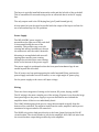
Trans-Oceanic VHF Ducting A Simple Multifunction Beacon By Dave Pedersen N7BHC Overview Quite often band openings go unnoticed because of a lack of activity. Beacons are useful propagation indicators. They transmit a signal at a stable frequency, power, and beam pattern. This allows distant receiving stations to have a signal to monitor for possible band openings. Beacons are especially useful in locations that don't have a lot of regular activity on the band of interest. In many instances, DX operators have limited resources to invest in equipment. HF operation promises many more QSOs than VHF, so HF stations and operations are much more common. Most have little or no interest in or equipment available for VHF. A beacon project could build and deploy beacons at key locations for the purpose of studying extreme-‐range trans-‐oceanic ducting propagation. These beacons would be optimized for studying long-‐range trans-‐ oceanic ducting. The initial focus would be on the North and South Atlantic oceans. Beacon Design Considerations There are many different design criteria for beacons. Various tradeoffs are made as the beacon design is optimized for its specific purpose. Before a design can be started, the intended objective needs to be well defined. In this discussion, we’re looking for a beacon to explore very long-‐range paths from remote areas. This implies high erp over a specific path in order to optimize the chances for successful communications. The beacon is to do double duty and function as a station to work DX as well. These design criteria will define the beacon design and implementation. Locations. These beacons will mostly be deployed in remote areas where there is little or no existing VHF DX activity. They need to address issues such as poor electrical power, overseas shipping, and very limited local spare parts availability, Mode. Modern digital modes such as JT-‐65B and WSPR provide several dB advantage for weak signal detection over long paths. However, not as many listening stations are equipped to listen for and work the digital modes. In addition, these beacons will be in remote areas often without the accurate time reference source that JT-‐65 and WSPR require. It’s also unlikely that there will be a computer on site. PSK-‐31 would be another good digital mode, and it does not require an accurate time reference. PSK-‐31 still needs a computer on site, although in the past small PSK-‐31 keyers were available. If a PSK-‐31 keyer were available, it would be well worth considering for remote beacons. There is one mode that is easy to decode, simple to implement, uses readily available keyers, and is widely recognized. Simple on-‐off keyed CW. An alternative would be MCW, but that adds complexity and increases duty cycle. Transceive capability. The beacons for researching new trans-‐oceanic paths will be vital to detecting band openings. In order to exploit the detected conditions and actually work DX, a transceiver is required. By using a multimode transceiver as the basis of the beacon, both functions are supported in a single package. Power output. The radio, amplifier, and power supply should all be run well below their maximum ratings. This reduces heat and increases longevity and reliability. As high erp is desired, a160-‐watt amplifier turned down to 100 watts is ideal. Antenna selections. The antenna system needs to be selected for the intended propagation path. The antenna to be used for long range beacons need to have as much gain as possible while still addressing the desired target region. Coastal stations would probably use a unidirectional antenna system beamed towards the target area. If all the target stations are within a narrow beam angle, a high gain single yagi with 15-‐25 elements might be suitable. However, if the target stations are spread over a large angle, e.g. a beacon in the US aimed at Europe and North Africa, a much wider horizontal beamwidth is required. A small yagi of 5-‐6 elements will give a 50-‐60º E-‐plane beamwidth, but its low gain would not increase the overall erp very much. The solution is to use a large vertical array of the small antennas, with 4 – 16 yagis stacked vertically. Mid Ocean stations on islands have a bit of a dilemma. They typically need to beam at coastal stations in several directions. They need either omni or bidirectional antennas. These might be several stacked loops, or a wire based H-‐Quad-‐bay. The basic H-‐Double-‐bay antenna can be seen at W4GRW’s web page at http://wvfisher.googlepages.com/hdoublebay. The concept can be expanded to use 4, 6, or even 8 or more slots. An advantage of this design is low cost and complexity. Off-the-shelf components. All items used in the system should be readily available, and not require custom electronics. This improves the reparability and lessens the design and construction complexity and cost. Cost. Several beacons will be required to cover the paths of interest. It is important to keep the cost as slow as possible. Overseas shipping needs to be figured into the cost as well. In some cases, import duty will have to be paid as well, which in some countries can be over 50% of the equipment value. Many of these beacons will need to be subsidized or paid for entirely by donation. An arbitrary maximum value of $1000, including shipping, per site has been applied. The Simple Multifunction Beacon concept designed by Dave N7BHC is described in this article. It is based on a multimode radio with an amplifier and keyer. The system operates as a beacon most of the time. When a band opening is reported, the local operator can turn off the beacon and use the same equipment to work DX. Local Host Finding a local ham that is interested and catches the vision to try extreme long-‐ range tropo experiments is probably the biggest challenge of all. It may require years of patience and effort on their part. A local ham radio operator interested in trying VHF is absolutely vital to host the beacon. The local host will find a site for the beacon, install and maintain the equipment, and work the DX when the band opens. The local host operator will also be responsible for licensing of the beacon. Simple Multifunction Beacon Let’s take an in depth look now at the design criteria and decisions for the simple multifunction beacon. We will also review the constriction techniques for the first several beacons that have already been built. Concept The Simple Multifunction Beacon concept designed by N7BHC is based on a small multimode radio with an amplifier and keyer. The system operates as a beacon most of the time. When a band opening is reported, the local operator can turn off the beacon and use the same equipment to work DX. This allows two-‐way contacts to be made over the same equipment. The design on this web page profiles a VHF beacon operating on the 144 MHz (2m) amateur band, but the principles are directly applicable to a 430 MHz (70cm) beacon as well, or even to other bands. Design The design selected is fairly simple. There are undoubtedly more efficient modes and equipment to use. However, simplicity and reliability are considered extremely important. Another overarching consideration is size and weight as they shipping costs to remote locations can be very expensive. The design is based around an all-‐mode 2m radio. A simple memory keyer generates CW at about 12 wpm Morse code. The radio can also be used as an SSB or CW transceiver when the band is open. The radio drives a 160-‐watt amplifier. The output power on the radio is reduced in beacon mode to run the amplifier at the 100 watt output level, keeping the amplifier cool and increasing reliability and MTBF. The radio is switched to full power in operate mode to boost the final output to the full 160 watts. A switching power supply rounds out the equipment lineup. The whole assembly is assembled on a 3U standard 19" wide rack shelf, about 18" deep. Equipment Selection Many various products were considered and tested in coming up with a simple and reliable beacon / transceiver station. Radio. The radio forms the basis of the simple multifunction beacon. It needs to be capable of operating in CW as a beacon, and in CW, SSB, FM, or digital modes when used for two-‐way communications. This means an all-‐mode radio is required. Models are available for both mobile and base station installation. The mobile radios are used in this beacon design to cut down on weight and size. Base station radios would be adequate or even better performers, and can be used if size and weight are not factors to be considered. Another consideration is that the radio needs to be a VHF use only model. There is a risk that if an all-‐band radio covering HF is provided on a beacon shipped to a remote location, it may eventually be removed from the beacon and put to use on HF, which would mean the beacon would be taken off the air. The radio and amplifier selection need to be considered together. The radio at its maximum power should drive the amplifier to full output in two-‐way operation. The radio should also have a low power mode that can be adjusted to drive the amplifier to the desired output level in beacon mode. Several models of radio were considered for the beacon design, and several were tested before selecting the Kenwood TR-‐751A for the 2m band. The TR-‐851A is the 70cm equivalent. The radios that were considered are: • Kenwood TR-‐9000 and TR-‐9130. These radios were tested and functioned well in beacon mode. They are older models, and the receivers are not as good as more modern radios. They do require a good receive preamp when used in two-‐way mode. The biggest downfall of these units is that they lose their programmed frequency and mode memory when DC power is removed. The memories would need to be reprogrammed after every power failure at the site, requiring a local operator who can make repeated trips to the beacon site. If the beacon is not monitored often, it may even be off the air for weeks or months before the problem is found and rectified. • Kenwood TR-‐751A. These radios are the next generation after the 9000 and 9130. They have very good receivers, and retain their memories if power is removed. The radio has adjustable low and high power settings. It also provides a relay to key the amplifier, eliminating relay chattering in the amplifier. This radio is also readily available on the used market at very reasonable prices. • Kenwood TM-‐255A. This would probably be the ideal radio for the beacon. It has excellent sensitivity, and was the final generation of 2m all-‐mode single band mobile radios produced. However, it is quite scarce on the used market, and sells for 50-‐100% more than the TR-‐751A. It is also larger, making integration onto the 19" rack shelf more difficult. The TM-‐455A is the UHF version. • Icom IC-‐260A and IC-‐290A/E/H. These radios are of the same generation as the Kenwood TR-‐9000 and TR-‐9130. They also lose programmed memory data if power is removed, and were therefore not considered suitable. • Yaesu FT-‐480R. This is another pretty good performer of the same generation as the TR-‐9130 and IC-‐290A. It does not lose its memories of power is removed, but it only puts out 10 watts and is fairly large, making mounting difficult in the rack-‐mount shelf configuration chosen. Keyer. The keyer's function is to generate the beacon sequence. The simple beacon transmits CW, so a simple memory keyer would suffice, with the radio operating in CW mode. An improved beacon would use both a digital mode such as JT65, WSPR, or PSK31, and CW on alternate sequences. The digital mode would provide the weak signal enhancement of the mode, while many more operators not equipped to decode the digital modes could receive CW. One additional complication of the JT-‐65 or WSPR modes is that the keyed sequence needs toe be transmitted at precise time slots. That would increase the complexity and cost of the entire beacon. The simple, CW keyer is the chosen solution on these simple multifunction beacons. • Several CW memory keyers such as the PicoKeyer were evaluated. While they did the job, setup required a CW key or paddle. They did work, and are viable options. • The ID-‐O-‐Matic from Hamgadgets was selected as it is designed with beacon operation as one of its modes. It is programmed via an RS-‐232 serial port, and can be built in about an hour. Dale Botkin at Hamgadgets provides excellent technical support. Amplifier. Several models were considered. Reliability and ruggedness are vital for beacons installed in remote locations. As the amplifiers considered were designed for intermittent service, external fan cooling is required. The FCC limit in the US for unattended beacon stations is 100 watts output, so 160-‐watt amplifiers were selected. The radio's low power output is adjusted to provide the correct drive required for the amplifier to operate at the 100 watt output level. This also helps the amplifier run cooler, further increasing reliability. Two amplifiers were ultimately selected as being suitable. • rfConcepst 25/160 watt models. There are several models available. The most commonly used is the rfc 2/315. Some models do not have external hard PTT keying. This is required for reliable keying, especially at low CW speeds. A weak point on these amplifiers is the rear panel fuse holder that makes poor contact to the fuse, leading to excessive slow heating of the fuse and subsequent failure. Research has shown that the fuse holder cap easily exceeds 80ºF above ambient air temperature after just a few minutes of operation. The fuse should be jumpered internally and external fusing installed. Another problem encountered with one unit was no heat sink compound on the final transistors, leading to early failure. • Mirage B2516G. Earlier models of this amplifier are more reliable and better built than the newer ones. The fusing on these amplifiers is internal on the circuit board. While the fuse holder makes a much better connection to the fuse, and generates much lease heat on the contacts, it should be jumpered internally and external fusing employed. This again is in the interest of reliability and ease of field maintenance. Power Supply. The radio and amplifier require 35 Amps at 13.8 volts DC when transmitting on high power. A PSU of 45-‐50 Amps provides enough reserve capacity to operate reliability. While a linear supply is very capable of meeting the power requirement, a switching supply was chosen to reduce the weight for overseas shipment. A 45 Amp MFJ power supply was selected. MFJ-‐4245MV. This power supply provides 40 Amp continuous and 45 Amp surge current capacity at 13.8 volts. They have proven very reliable over many years of use with not a single failure experienced. An external switch selects either 110 or 220 VAC input. Metering indicates the supplied voltage and current draw. Two fans cool this supply well even in moderately high power beacon use. The exhaust air is quite cool. Careful positioning of the power supply directs the exhaust air across the radio heatsink, doing double duty in cooling the power supply and radio. How to build a Simple Multifunction Beacon The simple multifunction beacon can built onto any suitable frame, or even left on a desktop. The physical layout ultimately chosen is a 19" rack shelf, 5.25" high and 18" or more deeper. This allows the entire bacon to be assembled in a compact package with all components anchored in place, increasing reliability and simplifying shipping and installation. Locations without a rack to mount the beacon in can easily manufacture a metal or wood cabinet to house the rack shelf. Rack Shelf. The standard design frame is a 19" vented rack shelf. A 3U 5.25" high shelf makes a compact assembly. A 4U 7" high shelf would offer additional top clearance for better cooling in hot environments. The shelf needs to be at least 18" deep to accommodate the depth of radio with the power supply behind it. The venting slots make installing the amplifier and other equipment very simple with self-‐tapping sheet metal screws inserted from the bottom. Rack front panel. A vented front panel protects the equipment while allowing reasonable airflow. Cutouts are made to go around the radio and amplifier. The cutouts are made larger than the radio and amplifier by 1/8" to 1/4". The sharp metal edges of the cutouts are covered with a rubber or plastic edge guard. I have found the outer vinyl covering of 1/4" coaxial cable to be a very good low-‐cost solution. Slice a length of coax down its length with a sharp knife or razor blade. Cut to length with 45º beveled corners and slide over the sharp metal edge. The keyer on-‐off switch, CW key jack, and a microphone hanger are attached to the front of the rack panel. Layout. The photo to the right shows the overall layout. The radio is on the front right, with the power supply on the right rear. The amplifier is on the front left, with DC power distribution at the left rear. The keyer location is not critical, but is usually nestled near the front between the radio and the right edge of the rack shelf to facilitate the Keyer On/Off switch and an external key jack if desired. Radio. The TR-‐751A radio is mounted on the front right side of the rack shelf, and has a few small modifications to make it easy to adjust some internal controls when fixed inside the rack shelf. It is positioned so the front panel metal work is 1/8" in front of the rack front panel ears. It should be mounted a few inches from the side of the rack shelf to allow for cooling. If the radio's original clamshell mobile mount is not available, simple aluminum L-‐brackets are used to support the radio. The height of the radio can be optimized when using the L-‐brackets so that the middle of the heatsink on the rear panel is the same height as the middle of the power supply exhaust fan. There are three internal trimpots that may need adjustment from time to time. Drilling three small holes in the top cover of the radio makes these accessible without having to remove the radio from the rack shelf and remove the top cover. They trimpots to be adjusted are for: • CW Sidetone level. Some locations are manned, and the continual sound of the CW sidetone appears to not be universally appreciated. • Break-‐In delay. Adjust this control so that the radio does not chatter between receive and transmit between characters while transmitting. • Low Power Drive level. Adjust this control so that the drive produced in low power drives the amplifier to the desired output power. Most amplifiers tested need about 9-‐10 watts to produce 100 watts output. The TR-‐751A provides a relay closure to key the PTT line of an external amplifier. The 4-‐pin connector is very hard to find these days, and most of the time one needs to be manufactured. Fortunately this is quite easy. Here is the process I use. • • • • • • Remove two pins from a DB9 male connector. Apply heat with a soldering iron until the plastic softens, and pull the pins out with a pair of needle nose pliers. Solder a length of hookup wire to each pin. Support the radio exactly vertically with the face down. Place a piece of masking tape across the rear panel accessory socket. Spread a thin layer of Vaseline or silicone grease across the tape over the area of the connector. Push the two pins with wire previously described through the masking tape and into their two pins. Be sure to use the correct two locations in the socket. • • • • Modify the plastic shell from a 1/8" phone plug by cutting the narrow end off, or find some other length of 1/4" plastic tube about 3/4" long. Feed it down over the wires from the two pins. Mix up some 5-‐minute two-‐part epoxy. Carefully drip it down into the connector shell while holding the shell firmly against the masking tape to prevent leakage out the bottom. I use a toothpick for this process. After 5 minutes, the epoxy will have set well enough to stay in place without holding the connector shell. Let it rest another 5-‐10 minutes, then pull it off the rear of the radio. Remove the masking tape. The connector is now finished. Amplifier. The amplifier is mounted on the right front of the rack shelf. It requires a small modification to operate reliably in long-‐term beacon use. Mounting. The amplifier draws cooling air in through vents on its bottom and side. To enhance cooling, replace the rubber standoff feet with larger 1/2" high self-‐adhesive feet. The amplifier is secured to the rack shelf with self-‐ tapping metal screws that come through the slots on the rack shelf and screw into the narrow slots on the bottom of the amplifier. If your amplifier does not have vent slots on the bottom, remove the amplifier cover, and position it in place on the rack shelf. Observe where components are located in the amplifier, and then drill four holes through the shelf slots and up into the amplifier case. Alternatively, L-‐brackets that secure to the screws on the side of the case to the heatsink could be used. Fuse. The fuse holders and fuses on the amplifiers are weak points. In high duty-‐ cycle extended operation, the fuses tend to age quickly and fail after 1-‐3 months. On the rfc amplifiers, the poor fuse holder-‐fuse connection has a little more resistance than desirable. This causes additional heating of the fuse holder and fuse. Temperatures of more than 80ºF above ambient on the back of the fuse holder have been measured after just 10 minutes of operation. The solution is to jumper the internal fuse holders and use an external fuse, or better yet, a circuit breaker. A 30 Amp magnetically tripped external circuit breaker replaces the fuse. These are more reliable than the thermally tripped breakers in this application. Cooling. The amplifiers are not designed for extended, high duty cycle operation. Although the CW transmission is about 30% duty cycle, and 15 second receive periods every minute allow additional cool down time, the amplifiers still run hot, shortening the component life. Two 80mm muffin fans provide additional cooling. The fans use ball roller bearings for long, quiet operation. They are run at 13.8 volts off the primary supply. The amplifier heatsink runs at less than 5ºF above ambient air with two fans. The fans are glued to each other with superglue, and then superglued to the heatsink, blowing air down onto the heatsink. Fan guards protect prying fingers and prevent any wires or tools from falling into the blades. Keying. The amplifiers should be hard keyed for PTT rather than rely on RF keying. The Mirage amplifiers use a closure to ground. The rf Concepts amplifiers can either use a ground or +12 volt line for keying. Set the jumper in the rfc amplifiers to use ground for keying (move the wire to the (-‐) pin internally). This PTT line is keyed by the relay output from the TR-‐751A, Preamp. The preamp is normally left OFF to avoid wear on the preamp relay. It also affords an extra level of protection from nearby static discharges while receiving. The preamp is turned on when the beacon is being used as a standard radio to work DX. Keyer. The ID-‐O-‐Matic keyer kit is very inexpensive and easy to build. Here are few extra pointers. • • • Observe antistatic procedures while handling the FETs and the PIC processor. Use an external 10K ohm trimpot in line with the speaker to reduce the sidetone level. If the keyer does not operate properly, check for incorrect settings in the additional parameters shown by setting Repeater (Y) can prevent operation, even if the Repeater (N) setting is used. One can use the settings for "Beacon" mode, but there is an even simpler setup suggested by Dale at HamGadgets. The settings I use on the ID-‐O-‐Matic keyers are shown below. • • • • • • • • • • ID Time 15 (15 seconds Rx time between beacon transmissions) Yellow time 0 Blink time 0 ID Msg callsign/B grid callsign/B grid callsign/B grid :15: (call and grid 3x, 15 second carrier) Beacon Msg (blank) Alternate Msg (blank) Auto CW ID Y CW Speed 13 ID Audio Tone 702 Repeater N The keyer is typically installed between the radio and the left side of the rack shelf. This is convenient for external wiring to the on-‐off switch that is in the DC supply line. The only output used is the CW keying line (pin 5) and Ground (pin 6). A front-‐panel jack can be wired in parallel with the output of the keyer to allow the use of an external key for CW operation. Power Supply. The MFJ-‐4245MV power supply is mounted on the right rear of the rack shelf. It is mounted facing the rear of the assembly. This permits easy access for viewing and wiring. In addition, it directs the exhaust air onto the radio's heatsink. Mounting is accomplished with two self-‐ tapping sheet metal screws coming through the rack shelf slots onto existing holes on the bottom of the power supply. The power supply is positioned so that the front panel attachment lugs do not extend beyond the rack shelf. The AC power cord can push up against the radio heatsink. Either position the power supply and radio to avoid a conflict, or use a right-‐angle AC power plug. Set the power supply to the correct AC input voltage. Wiring. There are three categories of wiring on the beacon; DC power, keying, and RF. The DC wiring is the most complex part of the wiring. All power is run from the large front panel lugs on the power supply to a power distribution area behind the amplifier where all devices are individually fused. The 8 AWG black negative lead goes to a large bolt mounted vertically from the bottom of the rack shelf. The negative leads from the radio, amplifier, and keyer are terminated to lugs attached to the same bolt. The 8AWG red positive lead goes directly to the lower (input) bolt on the 30A DC circuit breaker. The circuit breaker is just for the amplifier. An 8 AWG red wire from the circuit breaker output bolt goes directly to the amplifier. An 8 AWG red wire goes from the lower (input) bolt on the circuit breaker to the DC fuse panel. This fuse panel uses blade automotive fuses and holder as they are most commonly available overseas. A 10A circuit breaker is used for the radio, 3A for the fans, and 1A for the keyer. Individual wires go to the radio, keyer, and a single wire feeds the two fans that are wired in parallel. Spare fuses should be stored with the beacon. The keying wiring connects the keyer and front panel key jack to the radio, and the radio to the amplifier. The keyer outputs on pins 5 and 6 are CW keying and ground. These go to the Key input on the radio, a 1/8" mono plug. A 1/8" mono jack can be mounted on the front panel if an external key will be used to operate CW. It should be wired in parallel with the keyer output lines. The TR-‐751A provides a relay closure to key the amplifier. The amplifier side uses an RCA phono connector. If a different radio is used which does not have a relay output, it may have a PTT line that goes low on transmit which could key the amplifier. In addition, the keyer has a PTT output (pin 4) that can be used to key the amplifier directly. The RF wiring is just a cable from the radio to the amplifier. My preference is to use an RG-‐142/U double-‐shielded teflon cable. The antenna can connect directly to the amplifier output or through a wattmeter. Surge Protection. The two cables to provide surge protection on are the AC power line and the antenna lead. Heavy duty AC surge protectors like the ICE 330 or 331 (110 or 220 VAC) are ideal. Consumer grade products tend to fail easily in harsh environments. RF surge protection should be installed on the antenna lead at the building entrance. The ICE 302 and PolyPhaser IS-‐50NX are good products.