1
Ope r_ator's _Man Ual
CRRFTSMRN
°
61/8
JOINTER/PLANER
Model No.
351.227240
CAUTION: Read and follow
all Safety Rul_'sand Operating
Instructionsbefore First Use
of this Product.
Sears, Roebuck and Co., Hoffman
'3155.00 Draft (04103/98)
Estates, IL 60179 U.S.A.
PREPARE WORK AREA FOR JOB
Warranty......
: ...........................
Safety Rules... ...........................
Operation ...............................
Maintenance ..............................
Troubleshooting .........................
Parts Illustration and List ..................
Keep work area clean. Cluttered work areas invite
accidents.
•
Do not use power tools in dangerous environments.
2
2-3
Unpacking.. ...............................
Assembly ................................
Installation ...............................
•
3
• Do not use power tools in damp or wet locations. Do
not expose power tools to rain.
4-7
7-8
• Work area should be properly lighted.
8-13
13
14-15
16-20
--FULL ONE YEAR WARRANTY ON
CRAFTSMAN
61/8"JOINTEPJPLANER
If this Craftsman Jointer/Planer fails due to a defect in
material or workmanship within one year from the date
of purchase, contact the nearest Sears in-home major
brand repair service in the United States, and Sears will
repair it, free of charge.
•
Proper electrical receptacle should be available for
tool. Three prong plug should be plugged directly
into properly grounded, three-prong receptacle.
•
Extension cords should have a grounding prong and
the three wires of the extension cord should be of
the correct gauge.
•
Keep visitors at a safe distance from work area.
•
Keep children out of workplace.Make workshop childproof. Use padlocks, master switches or remove switch
keys to prevent any unintentionaluse of power tools.
TOOL SHOULD
•
Always unplug tool prior to inspection.
• Consult manual for specific maintaining and adjusting procedures.
If this jointer/planer is used for commercial or rental
purposes, this warranty will apply for 90 days from the
date of purchase.
This warranty applies only while the product is in the
United States. This warranty gives you specific legal
rights and you may also have other rightswhich vary
from state to state.
Sears, Roebuck and Co., Dept. 817WA, Hoffman
Estates, IL 60179
•
Keep tool lubricated and clean for safest operation.
•
Remove adjusting tools. Form habit of checking to
see that adjusting tools are removed before switching machine on.
•
Keep all parts in working order. Check to determine
that the guard or other parts will operate properly
and perform their intended function.
• Check for damaged parts. Check for alignment of
moving parts, binding, breakage, mounting and any
other condition that may affect a tool's operation.
•
WARNING: For your own safety, read all of the rules
and precautions before operating tool.
CAUTION: Always follow proper operating procedures
as defined in this manual even if you are familiar with
use of this or similar tools. Remember that being careless for even a fraction of a second can result in severe
personal injTu
ry.
BE PREPARED
BE MAINTAINED
A guard or other part that is damaged should be
properly repaired or replaced. Do not perform
makeshift repairs. (Use parts list provided to order
replacement parts.)
KNOW HOW TO USE TOOL
FOR JOB
•
Use right tool for job. Do not force tool or attachment
to do a job for which it was not designed.
•
Disconnect tool when changing blades.
•
Wear proper apparel. Do not wear loose clothing,
gloves, neckties, rings, bracelets or other jewelry
which may gentcaught in moving parts of machine.
Avoid accidental start-up. Make sure that the switch
is in the OFF position before plugging in.
•
Do not force tool. It will work most efficiently at the
rate for which it was designed.
• Wear protective hair covering to contain long hair.
•
Keep handsaway
surfaces.
• Wear safety glasses complying with United States
ANSI Z87.1. Everyday glasses have only impact
resistant lenses. They are NOT safety glasses.
•
Never leave tool running unattended. Turn the power
off and do not leave tool until it comes to a complete
stop.
•
Wear face mask or dust mask if operation is dusty.
•
Do not overreach. Keep proper footing and balance.
•
Be alert and think clearly. Never operate power tools
when tired, intoxicated or when taking medications
that cause drowsiness.
•
Never stand on tool. Serious injury could occur if tool is
tipped or if blade is unintentionally contacted.
•
Know your tool. Learn the tool's operation, application and specific limitations.
•
• Wear safety shoes with non-slip soles.
2
from moving parts add cutting
• Us_ recommended accessodes (refer to page 17).
Use of improper accossodes may cause risk of
injury to persons.
•
Handle workpiece correctly. Protect hands from possible injury. ....
•
Turn machine off if it jams. Blade jams when it digs
too deeply into workpiece. (Motor force keeps it
stuck in the work.)
• Always keep drive, cutterhead and blade guards in
place and in proper operating condition.
•
Feed work into blade or cutter against direction of
rotation.
CAUTION: Think safety! Safety is a combination of
operator common sense and alertness at all times
when tool is being used.
F
G
H
_ush S_
(2) __.
Top Panel
Stand Front Panel
I
Stand Rear Panel
J
K
Stiffners (2)
Lower Motor Bracket
L
M
Upper Motor Bracket
Vertical Motor Bracket
N
Knife Guard
O
P
Pulley Guard
Handwheel (2)
Q
Cover (2)
• Motor Pulley with Set Screws
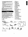
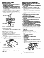
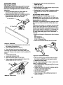
Refer to Figure 1 below.
Check for shipping damage. If damage has occurred, a
claim must be filed with carder. Check for completeness. Immediately report missing parts to dealer.
•
Knife gauge (2)
•
Knife gauge rod (1)
•
Leveling feet (4)
•
3 CMI-10 Retaining ring (4)
•
#8 Serrated washer (2)
•
'/," Flat washer (6)
• 3Is"Lockwasher (3)
• "1=" Flat washer (34)
The jointer/planer is shipped complete in one carton
and includes steel legs. Additional parts which need to
be fastened to jointer/planer should be located and
accounted for before assembling.
• %" Lockwasher (30)
,, #8-32 x % Pan head screw (2)
NOTE: Although compact, the jointerlplaner is heavy. At
least two people are required to lift the tool.
A Jointer Bed Assembly
B Fence
C Motor
•
11,-20 x 1/=Pan head screw (6)
•
%"-16 Hex nut (8)
•
s/16"-18Hex nut (30)
• 3/r16 x 3/," Hex head bolt (3)
•
Rear Guard
Rgure I - Unpacking
V-Belt
Hardware bag includes:
_-WARNING: Do not attempt to operate tool until it is
completely assembled according to the instructions.
D
E
,
3
%-18 x 31,"Carriage bolt (30)
-
i ....
WARNING: Do not attempt assembly if parts are
missing. Use this manual to order replacement parts.
ASSEMBLE
STAND
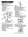
Refer to Figures I and 2, pages 3 and 4.
•
•
_
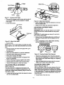
Rgure 3
Install Leveling Feet
Identify and locate the following parts from the hardware bag:
%-18 x 3/4.Carriage bolt (16)
,3/=. Flat washer (16)
%" Lockwasher (16)
51,6"-18Hex nut (16)
•
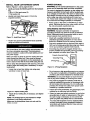
Install leveling feet as shown below.
NOTE: You may have to adjust leveling feet prior to
installing the completely assembled jointer/planer.
Identify and locate the following parts:
Top panel ° G
Stand front panel - H
Stand rear panel - I
Stiffners - J (2)
INSTALL
MOTOR
BRACKETS
Refer to Figures 1, 4, 5 and 6, pages 3, 4 and 5.
•
Identify and locate the following parts from the hardware bag:
% 18 x 3/,"Carriage bolt (10)
,3/=. Rat washer (10)
'/=" Lockwasher (10)
s/,6"-18 Hex nut (10)
•
Identify and locate the following parts:
Lower motor bracket - K
Upper motor bracket - L
Vertical motor bracket - M
•
Install lower motor bracket across stiffners (Figure 4)
using four carriage bolts, ,3/=, flat washers, %" lockwashers and 5/,6"-18hex nuts. Hand tighten hex nuts.
Panel
Lockwasher
Washer
FrontPanel
Switch Box
ped Holes
' Top Panel
Rgure 2 - Assemble
Stand
_- Place the top panel on the floor upside down
•
Figure 4 - Install Lower Motor Bracket
Attach front and rear panels using the carriage bolts,
washers, hex nuts and stiffners (see Figure 2).
Attach vertical motor bracket to lower motor bracket
(Figure 5) using the slots on the lower motor bracket,
two carriage bolts, ,3/=, flat washers, %" Iockwashers
and 3113"-18
hex nuts. Hand tighten hex nuts.
NOTE: Make sure that the front panel (with switch box)
is mounted opposite to four tapped holes in top panel.
INSTALL
LEVELING
Refer to Figure 3.
•
FEET
-"
Identify and locate the following parts from the hardware bag:
:
Leveling Feet (4)
3/s"Flat washers (4)
3/,"-16 Hex nuts (8)
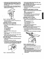
Figure 5 - Install Vertical Motor Bracket
4
•
.
Install upper motor bracket under flange of vertical
motor bracket (Figure 6) and attach it using two cardage bolts, "/=_'fiat washers, =/_,"Iockwashers and
s/,,'-18 hex nuts.
• Attach motor to bracket using cardage bolts, wash_ers, IodoNashers and hex nuts.
Attach top pahel to upper motor bracket (Figure 6)
using two carriage bolts, '¥=" fiat washers, '/,," lockwashers and %"-18 he)( nuts.
•
Slowly set the stand upright.
•
Route the cord through the grommet in the stand
front panel.
NOTE: Hand tighten only.You may have to adjust motor
position later when-V=belt is installed.
ASSEMBLE
SWlTCHBOX
TO STAND
•
Identifyand locate the following_
bag:
#8-32 x s/=.Pan Head Screw (2)
#8 Serrated Washer (2)
•
Slide the switchbox in the slot on the front panel
•
Attach switchbox to stand using the pan head
screws and serrated washers.
ASSEMBLE
from the hardware
BED TO STAND
Refer to Figures 1 and 8, pages 3 and 5.
Rgure 6 - Install Upper Motor Bracket
•
Identify_ locate the followingparts from the hardware
bag:
3/8-16x 3/,, Hex head bolt (3)
%" Lockwasher (3)
'/,-20 x '/="Pan head screw (2)
'/,"Flat washer (2)
Identify and locate the following parts from the hardware bag:
Motor Pulley
Sl, 18 x 31,"Carriage bolt (4)
"/3="Flat washer (4)
Sl,.. Lockwasher (4)
'/,.'-18 Hex nut (4)
•
Identify and locate the following parts:
Handwheels-P and V-Belt-E,
•
Identify and locate the following parts:
Motor - C
•
•
Remove tape from motor shaft. Make sure the key
stays in the slot.
•
Slide the motor pulley onto the motor shaft until flat
side of pulley hits shoulder on shaft.
•
Place stand upright and tighten all leg set hex nuts
with open end wrench.
ASSEMBLE
MOTOR
TO STAND
Refer to Figures 1 and 7, pages 3 and 5.
•
WARNING: Although compact, this tool is heavy. At
least two people are required to lift the tool.
Set the jointer bed assembly on top of the stand.
• Align the three holes in the bed with the three slots
on the stand.
Attach the three bolts and Iockwashers and tighten.
NOTE: Make sure hat the hub (shoulder) on the pulley Is on the outside.
•
Tighte_ the two setscrews in the pulley using 3mm
hex wrench,
•
•
Set the stand assembly on the side.
Seat the motor on the vertical motor bracket and make
sure the slots on the motor base plate are aligned with
the slots on'the vertical motor bracket (see Figu;'_7).
Figure 8 - Assemble Bed to Stand
• Slip the V-belt over the drive pulley.
•
Lift the motor and slip the V-belt around the motor
pulley.
NOTE: Visually align the motor and drive pulleys and
tighten the motor mounting bolts.
• Slide the handwheel onto the elevation screw on the
infeed table and secure it using the screw and flat
washer. Repeat for attaching the handwheel to the
ouffeed table.
Rgure 7 - Assemble Motor to Stand
5
ASSEMBLE FENCE TO BED
KNIFE GUARD
Refer to Rgure 9, page 6.
• Remove the two nuts and washer from the bolt on
WARNING: Always keep knife guard in place and in
proper operating condition.
the bottom of.fence assembly.
mum width of cut. Do not position fence beyond rear
edge of cutterhead.
Reinstall the washer and two nuts onto the toggle bolt.
• Adjust the fence locking mechanism by tightening
the upper locking nut until only about 1/,of a tum of
the fence lock knob is possible.
•
Pass a '/," thick piece of wood over the cutterhead
between the guard and the fence.
•
The guard must return automatically to the "reset
position"against the fence when the wood piece is
removed.
•
If guard does not return automatically, the guard
spring must be adjusted.
'/, Turn
--
Key Slot
ADJUSTING
Fence Support
GUARD
Lock the fence in place.
•
Remove the pan head screw from the bottom of the
guard post.
•
Remove tension from knife guard by turning the
knob clockwise.
•
Pull and remove knife guard in '/=turn increments by
turning the tension knob and reinsertingthe guard post.
•
Repeat knife guard installation check.
• Snug the lower nut to the upper nut with an
adjustable wrench. This will lock adjustment in place.
•
INSTALL KNIFE GUARD
A'I-I'ACH PULLEY
Reinstall the pan head screw in the bottom of the
guard post.
GUARD
Refer to Figures 1 and 11, pages 3 and 6.
Refer to Figures 1 and 10, pages 3 and 6.
• Identify and locate Knife guard - N.
•
SPRING
NOTE: Do not overtighten the spring. Overtightening
may cause premature spring or knife guard breakage. If
the guard or spring breaks or malfunctions, do not use
the tool. Replace the defective parts before the tool is
put back in service.
Figure 9 - Assemble Fence to Bed
•
CHECK
• Turn the switch off and disconnect jointer/planer from
power source.
• Position the fence to the rear of the bed for maXi-
• Carefully lift the fence and place it onto the bed so
that the key slot on the fence is aligned with the key
in the fence support. The bolt will go through the slot
in the fence support.
•
INSTALLATION
•
Identifyand locate the following parts fromthe hardware
bag:
V,-20 x '/="Pan head screw (4)
V4"Flatwasher (4)
Remove the pan head screw from the bottom of the
guard post.
• Turn the spring-loaded knob one turn counterclockwise
Iookingdown through the hole in the infeed table.
• Identify and locate the following parts:
Pulley guard - 0
Cover - Q (2)
• Align the-slot in the guard post with the pin in the knob.
• Attach pulley guard to stand using four screws and
washers.
•
Install cover to either side of stand with the clips facing towards the outside.
Slot
Spdng
Loaded
Knob
Figure 10 - Install Knife Guard
,
Cover
Slide the guard post in the hole and over pin in the
knob.
• Reinstall the pan head screw in the bottom of the
._uar=_-i::)ost.
Rgure 11 - Attach Pulley Guard and Cover
•
6
Turn clips to lock cover in place.
uard
INSTALL REAR CUTTERHEAD
POWER SOURCE
GUARD
WARNING: Do not connect jointer/planer to the power
source until all assembly steps have been completed.
Refer to Figures I and12, pages 3 and 7.
•
Identifyand locate the followingparts from the hardware
bag:
'/,-20 x 'h" PEn head screw (2)
'/,'Flat washer (2)
•
The motor is designed for operation on the voltage and
frequency specified. Normal loads will be handled safely on voltages not more than 10% above or below specified voltage. Running the unit on voltages which are not
within range may cause overheating and motor burnout. Heavy loads require that voltage at motor terminals
be no less than the voltage specified on nameplate.
Identify and locate Rear guard - D from the
unpacked contents.
•
Power supply to the motor is co-ntr'olledby a rocker
switch. Removing the key from rocker switch will lock
the unit and prevent unauthorized use.
GROUNDING
WARNING: Improper connection of equipment
grounding conductor can result in the dsk of electrical
shock. Equipment should be grounded while in use to
protect operator from electrical shock.
Figure 12 - Install Rear Guard
•
• Check with a qualified electrician if you do not
understand grounding instructions or if you are in
doubt as to whether the tool is properly grounded.
Fasten rear guard to jointedplaner fence assembly
using two screws and washers.
• This tool is equipped with an approved cord rated at
150V and a 3-prong grounding type plug (see Figure
14) for your protection against shock hazards.
•
The jointer/planer with stand weighs approximately 200
Ibs. when completely assembled. The jointer/planer
must be installed in a place with ample lighting and correct power supply.
Grounding plug should be plugged directly into a
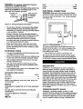
properly installed and grounded 3-prong groundingtype receptacle, as shown (see Figure 14).
PropedyGroundedOutlet
Make sure there is plenty of room for moving the workpiece through the entire cut. There must be enough
room that neither the operators nor the bystanders will
have to stand in line with the wood while using the tool.
GroundingProng
3-Prong
Bolt or clamp the jointedplaner with stand to a firm level
surface. Adjust the leveling feet if necessary. To adjust
leveling feet:
•
INSTRUCTIONS
Figure 14 - 3-Prong Receptacle
Loosen top nut and turn bottom nut using open
wrenches to raise or lower feet.
•
Do not remove or alter groundingprong in any manner.
In the event of a malfunctionor breakdown, grounding
providesa path of least resistancefor electrical shock.
WARNING: Do not permit fingers to touch the terminals of plug when installing or removing from outlet.
•
Plug must be plugged into matching outlet that is
propedy installed and grounded in accordance with
all local codes and ordinances. Do not modify plug
provided. If it will not fit in outlet, have proper outlet
installed by a qualified electrician.
•
Inspect tool cords periodically, andif damaged, have
repaired by an authorized service facility.
Figure 13 - Adjust Leveling Feet
•
• Green (or green and yellow) conductor in cord is the
grounding wire. If repair or replacement of the electric cord or plug is necessary, do not connect the
greer_'(or green and yellow) wire to a live terminal.
Adjust all four leveling feet, if necessary, and tighten
the nuts.
NOTE: The leveling feet are not intended for height
adjustment, only leveling adjustment.
•
Make sure the jointer/planer does not rock and the
tAhlA._ArA IAVAI_
7
A 2-prong wall receptacle must be replaced with a
properly grounded 3-prong receptacle installed in
accordance with National Electric Code and local
codes and ordinances.
WARNING: Any receptacle replacement s_uid be
performed by a qualified electrician.
_
Hertz..
3-Prong
_:,i...
.....
....
!..
:,._60
Phase .......
.........................
RPM ..................................
A temporary 3-prong to 2-prong groundingadapter (see
Figure 15) is available for connecting plugs to a two
pole outlet if it _s-properly grounded.
GroundingLug
i....:.:....
Single
5000
ELECTRICAL CONNECTIONS
Make Sure This
WARNING:
Is Connected
nected from power source before inspecting any wiring.
Make sure unit is turned off and discon-
To A Known
Ground
The unit is wired as illustrated in the wiring schematic
(see Figure 16).
2-Prong Receptacle
]31
° ]28
Rgure 15 - 2-Prong Receptacle with Adapter
•
---
Do not use a 3-prong to 2-prong grounding adapter
unless permitted by local and national codes and
Ordinances. (A 3-prong to 2-prong grounding adapter
is not permitted in Canada.)
Where a 3-prong to 2-prong grounding adapter is
permitted, the rigid green tab or terminal on the side
of the adapter must be securely connected to a
permanent electrical ground such as a properly
grounded water pipe, a properly grounded outlet box
or a properly grounded wire system.
•
Wire
Nut
Many cover plate screws, water pipes and outlet
boxes are not properly grounded. To ensure proper
ground, grounding means must be tested by a qualified electrician.
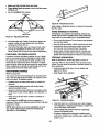
EXTENSION
Figure 16 ' Wiring Schematic I
The motor is assembled with an approved three conductor cord to be used on 120 volts as indicated. The
power supply to the motor is controlled by a double
pole locking rocker switch.
CORDS
• The use of any extension cord will cause some drop
in voltage and loss of power.
• Wires of the extension cord must be of sufficient size
•
•
Use only 3-wire extension cords having 3-prong
grounding type plugs and 3-pole receptacles which
accept the tool plug.
DESCRIPTION
Craftsman 6 %" jointer/planer is used to surface the
faces and edges of boards, produce a fiat surface on
warped boards and shape rabbets, bevels, chamfers
and tapers. The jointer/planer features heavy cast iron
infeed and outfeed tables with precision ground work
surfaces and leadscrews for precise table height adjustment. Rigid, center mount guide fence is provided with
bevel stops at 90 ° (from bed) and 45 ° .Tool comes with
locking rocker switch with removable key and push
blocks. Jointer/planer easily handles rough-cut lumber,
planes hard and soft woods up to 6 %" wide using a
three knife cutterhead, and takes cuts up to l/s",and up
to 1/=,rabbets.
If the extension cord is worn, cut or damaged in any
way, replace it immediately.
EXTENSION CORD LENGTH
Wire Size
A.W.G.
Upto 50 ft................................
16
50-100 ft ..................................
14
NOTE: Using extension cords over 100 ft. long is not
recommended.
.-.-
MOTOR
Jointer/planer is supplied with a 2 HP (max developed)
motor.
OPERATION
The 120 Volt AC universal motor has the:following
specifications:
Horsepower (Maximum Developed) ..............
Voltage ....
_e
: ............................
re_.. ..............................
Remove the key to prevent unauthorized use.
The power lines are inserted directly onto the switch.
The green ground line must remain securely fastened
to the frame to propedy protect against electrical shock.
to carry the current and maintain adequate voltage.
• Use the table to determine the minimum wire size
(A.W.G.) extension cord.
•
I
SAFETY
RULES
Jointing is a surfacing operation in which a small
amount of wood is removed from the edges and faces of
boards to get smooth, straight and even surfaces such
that the two edges that run across the planing blocks
would fit together perfectly, forming a seamless joint.
2
120
10.8
8
Planing refers to the sizing of lumber to a desired thickness while creating a level surface parallel to the opposite size of the board. Depth of cut is the term used to
indicate how deep the knives will cut into the workpiece.
•
A rabbet is a notch cut into the edge of workpiece.
The depth of cut is adjusted by the relative positioning
of the infeed table with respect to the cutterhead. Infeed
table can be raised or lowered using the handwheel.
DEPTH OF CUT
WARNING: Operation of any power tool can result in
foreign objects being thrown into eyes which can result
in severe eye damage. Always wear safety goggles
complying with United States ANSI Z87.1 (shown on
package) before commencing power tool operation.
Turning the handwheel counterclockwise will lower the
infeed table causing more wood to be removed from
workpiece. Turning the handwheel clockwise will raise
the infeed table cansing less wood to be removed from
workpiece.
WARNING: For your own safety, read all of the
instructions and safety precautions before operating
tool.
•
Keep jointer/planer maintained. Follow maintenance
in,'itructions(see page 13).
Do not make jointing, planing or rabbeting cuts deeper
than '/B".A stop pin is supplied to prevent planing or
jointing more than '/," depth of cut.
Know general power tool safety. Make sure all precautions are understood (see pages 2, 3 and 9).
POSITIONING
• Whenever adjusting or replacing any parts on
jointer/planer, turn switch off and remove plug from
power source.
FENCE
Refer to Figure 17.
WARNING: Turn jointer/planer off.and wait for all parts
to stop before adjusting fence.
•
Make sure all guards are properly attached and
securely fastened.
•
Make sure all moving parts are free from interference.
The fence can be tilted to any desired angle, and slide
it back and forth. To tilt fence:
•
Always wear eye protection or face shield.
•
Loosen tilt knob.
•
Make sure blades are aligned and properly attached
to cutterhead.
•
Move fence to desired angle.
•
Do not plug in jointer/planer unless switch is in "off"
position. After turning switch on, allow jointer/planer
to come to full speed before operating.
SlidingKnob
• Tighten knob.
_'l'ilt
Knob
\
• Keep hands clear of all moving parts.
• Do not force cut. Slowing or stalling will overheat
motor. Allow automatic feed to function properly.
•
Use quality lumber. Blades last longer and cuts are
smoother with good quality wood.
•
Do not perform jointing/planing operations on material shorter than 8 '/,", narrower than s//, or less than
'/," thick
•
Never make jointing or rabbeting cut deeper than '//'.
• Always keep cutterhead and knife guards in proper
working condition.
•
Maintain the proper relationships of infeed and outfeed'table surfaces and cutterhead blade path.
• Do not back the work toward the infeed table.
•
Support the workpiece adequately at all times during
operation; maintain control of the workpiece.
•
Use hold-dowrdpush blocks for jointing material narrower th_{n3" or planing material thinner than 3-.
•
Take precautions against kickback. Do not permit anyone to stand or cross in line of cutterhead's rotation.
Kickback or thrown debris will travel in this direction.
Figure 17 - Positioning Fence
The fence can be slide it across the jointer/planer bed
when the workpiece will not be cut across the full width
or when there is a need to make use of only a portion
of the knives. To slide fence:
Replace or sharpen knives as they become damaged
or dull.
•
Do not attempt to perform an abnormal or little used
operation without study and the use of adequate hold" _"own/push blocks, jigs, fixtures, stops and the like.
Loosen sliding knob.
•
Slide fence to desired position.
•
Tighten sliding knob.
When work is completed, restore fence to extreme rear
of the outfeed and infeed tables, but not beyond the
end of blades.
• Turn switch off and disconnect power whenever
jointer/planer is not in use.
•
•
9
ADJUSTING FENCE "
Refer to F'_ure 18 and 19.
Jointer/planer has fence bevel stops at 90 ° (from bed)
and 45 °. These stops are set at the factory, but may
have fallen out of alignment while in transit. To check for
squareness:
• Turn the stop screws so they touch the fence.
T'_hten jam nuts.
• Loosen the tilt knob.
Place an accurate square on outfeed table and
check fence while locked at 90 ° position.
• Make sure that the bottom of the outfeed side of the
fence rests firmly against the outfeed table and
against the head of the two stop screws.
•
Move the fence to any angle and then return it to the
index and check for accuracy.
•
Readjust the 90 ° and 45 ° stops if necessary until the
stop maintains an accurate and repeatable fence
setting.
•
ADJUSTING
KNIFE HEIGHT
Refer to Figures 20, 21 and 22, pages 10 and 11.
WARNING: Make sure the switch is in the "OFF" position and the tool is disconnected from the power source
before making any adjustment.
CAUTION: The cutterhead knives are extremely sharp.
Do not let your fingers contact the cutting edge at any
time.
To produce even surface on a workpiece, the knife edge
must be at the same distance from the axis of the cutterhead. The knife height comes adjusted from the factory and should require no adjustment.A knife gauge has
been provided to make knife height adjustment easy.
The knife height setting gauge must be assembled. To
assemble:
•
Identify and locate the following parts from hardware
bag.
Knife Gauge (2)
Knife Gauge Rod (1)
3 CMI-10 Retaining Ring
•
Attach the two inside retaining rings to the shaft.
Figure 18 - Fence Stop
• Make sure that the infeed table does not interfere with
the accuracy of measurement.
•
Lower the infeed tableto at least '/;6".
•
Check the fence for accuracy using the stops.
The fence must be square to the ouffeed table at 90 °
and at 45 °. If fence is not square it must be adjusted. To
adjust:
Loosen fence tilt knob.
•
Loosen _top screw jam nuts.
•
Move stop screws away from the fence.
•
Using a square as shown, square the fence to the
outfeed table and lock the tilt knob.
Rgure 20 - Assemble Knife Gauge
• Slide one of'the gauges onto the shaft and attach
the outside retaining ring to hold gauge in place.
• Repeat for the other gauge.
The knife height setting gauge is ready to check knife
height. To ch.eckknife height:
_
_
-I=hJWrete - Adjust Fence
10
•
Lower infeed table by turning the depth of cut handwheel clockwise.
•
Position the fence to the rear of the jointer, approximately '/," beyond the cutter knives.
•
Lock the fence in this position.
•
Remove the knife guard.
•
Place the gauge on the cutterhead as shown in
Figure 21, page 11.
Gauge
Bottom
View.........
Knife
Spdng
Wedge
Figure 21 - Checking Knife Height
• The pad of the gauge must be flush with the knife. If
not, the knife height must be adjusted. To adjust
knife height:
• -Loosen lock screws.
Figure 23 - AdjustTable Extension
•
Lock Screws
• Tighten the two bolts and recheck the alignment.
/
f
f
Using a straight edge, align the extension to be flush
with the outfeed table.
ADJUSTING
Wedge
OUTFEED
TABLE
Refer to Figure 24.
WARNING: Make sure that the switch is in the"OFF"
__Knife
position and the tool is disconnected from the power
source.
<_
Spdng
CAUTION: The knife edges are sharp. Do not let fingers contact cutting edge.
e_ead
•
• Place a straightedgeon the outfeed table extending
over the cutterhead as shown below..
Rgure 22. Adjust Knife Height
•
Raise oi"lower the outfeed table knob, until the outfeed level is exactly level with the highpoint of the
knives.
Remove knife.
NOTE: Due to rust or resin buildup, the knife may stick.
If this happens, use a flat head screwdriver to pry under
knife.
•
Remove all parts and clean thoroughly with a gum
and pitch remover.
•
Reinstall parts.
•
Make sure knife extend s '/,," past the cutterhead.
•
Slip-knife height setting gauge into place.
Steel StraightEdge J
Table
Figure 24 - Checking Outfeed Table Alignment
• Place-pads of gauge over knife.
Rotate the cutterhead by hand. The knives should
just touch the straightedge. If a knife is too low or too
high at either end, adjust knife height per "Adjusting
Knife Height".
After the outfeed table has been set at the correct
• Push down on gauge and knife until gauge rests
firmly on cutterhead.
-• Without releasing the gauge, tighten lock screws.
•
Release gauge and knife must be held in place.
•
Repeat the procedure for other two knives.
Table
height, lock in place using wing screws.
ADJUSTING
ADJUSTING TABLE EXTENSION
TABLE GIBS
-
i-
Refer to Figure 25, page 12.
Refer tO Figure 23.
Gibe are provided to take up all play between the mating dovetail ways of the base and infeed and outfeed
tables. Proper gib adjustment is necessary for operation
of the jointer/planer. The gibe are adjusted at the factory
and should require no further adjustment. However to
adjust the gibe:
• Loosen each of the lock nuts.
The table extension is adjusted at the factory and
should not require any additional adjustments. In the
event that is shifted during shipping, align it to the outfeed table. To align:
• Loosen the two hex head bolts that attach the extension to the outfeed table.
11
•
Make sure that the table locks are loose.
•
Rnger tigMen-_ach set screw in turn, until the screw
"bottoms out." "
•
8
Do not overtighten the screws.
LockNuts
Figure 26 - Sharpening Knives
Never install unbalanced knives or reground knives less
than '/," wide.
AVOID DAMAGE TO KNIVES
Jointer/planeris a precisionwoodworkingmachine and
shouldonly be used on qualitylumber.Using bad lumber
could result in a poor qualitycut on subsequent pieces.
Table Locks
--Flgur-e 25 - Adjusting Table Gibs
•
•
Recheck table play. If table is still loose, tighten set
screws. If table is snug, tighten lock nuts without
allowing set screws to turn.
Check that the table raises and lowers freely when
turning the handwheel. If there is too much resistance, loosen the set screws and repeat adjustment.
CHECKING
FOR WORN
Do not use dirty boards. Dirt and stones are abrasive
and will wear blade.
•
Remove nailsand staples.Jointershouldonly cut wood.
•
Avoid knots. Heavy cross-grain makes knots hard
and they can come loose and jam the jointer.
• Assess value of badly warped boards.Operator can
be tempted to use too deep of cut to square boards
quickly.Use several passes to maintain a level surface.
KNIVES
Condition of knives will affect precision of cut. If blade
wear is not observed when checking the knife height,
the quality of cut will indicate the knife condition. Dull
knives will tear rather than sever wood fiber. A raised
FEEDING
WORKPIECE
Refer to Figures 27, 28 and 29, pages 12 and 13.
Feed rate refers to rate at which wood is passed over
knives. An even feed will produce a uniform service. To
feed workpiece:
grain will occur when dull knives pound on wood where
there is difference in density. A raised ridge will be produced where the knives have been nicked.
SHARPENING
•
•
Hold the board firmly down on both tables and
against the fence.
•
Keep fingers close together.
KNIVES
Refer to Figure 26.
The knives can be honed individually by whetting them
with a fine sharpening stone. Make sure oilstone is flat
and is not worn. To sharpen knives:
•
Partially cover the stone with paper to protect the
table top.
• Position-infeed table so stone will contact blade
•
along its beveled surface.
Stroke the stone across knife from one side to other
while stone is also moved slightly in the direction of
feed.
•
Make sure to do the same number of strokes on
each place.
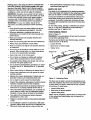
Rgure 27 - FeedingWorkplece
If the knives are nicked they must be replaced or
reground. They can be reground several times until they
become 91,, wide.
•
NOTE: Many shops do not have capabilities to resurface blades. Yellow pages should list =Sharpening
Services" or "Tool Grinding:
Feed the board at a continuous even rate of speed.
Any hesitation or stopping could cause a =step" to be
cut on the edge of the board.
• As thetrailiqg hand passes over the cutterhead,
remove the leading hand.
•
12
Continue feeding while placing the leading hand
behind the trailing hand until the entire length of the
board is cut.
•"-_#_;with'the
graia-whe_ve_'i
"l:;ossiblel
_ ::';
;:::'"
::;
;-:
. ii:
_
Jointer/planer will operate best if it is kept in good operating condition. Keep unit adjusted as described in
"Operation."
•
Rotation
Do not allow gum and pitch to accumulate on the
tables, fence, knives and knife guard.
• Apply a thin coat of paste type wax to the tables and
the fence so that the wood slides easily while feeding.
•
Do not allow chips to accumulate on the underside
of the jointer/planer.
•
Keep knives sharp (see =Sharpening Knives,"page
12). Sometimes replacing knives is less expensive
than resurfacing them. Keeping a spare set of knives
on hand is recommended. Knives should always be
sharpened or replaced in sets of three.
_n
Rotation
Figure 28 - Direction of Feed
•
If the nature of the workpiece is such that it must be
fed against the grain, take very light cuts and feed
slowly.
LUBRICATION
• When using long workpieces, to avoid injury from
slips or kickbacks and to exert even pressure on the
cutterhead, use extra supports (see Recommended
Accessories, page 17) at both infeed and outfeed
ends.
WARNING: Make sure the switch is in the =OFF" position and the tool is disconnected from the power
source.
•
Motor and cutterhead bearings are sealed and need
no lubrication.
•
Always use hold-down/push-blocks when jointing, or
rabbeting wood that is narrower than 3", planing
wood thinner than 3".
•
Fence guide and elevation screws should be cleaned
of debris and greased as needed.
•
Grasp the hold-down/push-blocks firmly.
•
Position the push-blocks flat on top of workpiece and
push the workpiece down against the table.
Use a hand-over-hand motion to maintain control
over the workpiece at all times.
•
Figure 29 - Feeding with Push-blocks
•
• Occasionally apply a few drops of light machine oil
to gibs to keep tables sliding free in relation to base.
MACHINED
....
When planing wo_rkpiecebetween 1/=.3/4,and narrower than the push-blocks, tilt the push-blocks so
that it clears the cutterhead guard while feeding.
13
SURFACES
•
Surface of tablesand fence must be kept smoothand
dean for easy work feed.
•
Apply a paste wax to surfaces to keep them slick
and prevent corrosion.
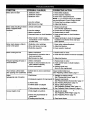
SYMPTOM
POSSIBLE CAUSE(S)
"L.d
Motor does not start
CORRECTIVE ACTION
1. Defective switch
1. Have switch replaced.
2. Defective capacitor
3. Defective motor
2. Have capacitor replaced.
4. Low line voltage
4. Correct low line voltage condition.
5. Adjust belt tension.
3. Have motor replaced/repaired.
NOTE: 1, 2, 3 must be done by a qualified
service technician; Consult Sears service.
5. Belt tension too high
Motor stalls (resulting in blown 1. Circuit overloaded
fuses or tripped circuit
breakers)
2. Low line voltage
3. Motor overloaded
4. Incorrect fuses on circuit breakers
.
Reduce circuit load
(turn off other appliances).
2. Correct low line voltage conditions.
3. Reduce load on motor.
4. Have correct fuses on circuit breakers
installed.
5. Short circuit in motor; loose
connections or worn insulation
on lead wires
5. Inspect terminals in motor for damaged
insulation and shorted wires and have
them replaced.
Motor starts slowly or fails to
come to full speed
1. Defective motorwindings
2. Drive belt tension too high
3. Defective capacitor
1. Have motor replaced/repaired.
2. Adjust belt tension.
3. Have capacitor replaced.
Motor running too hot
1. Motor overloaded
1. Reduce load on motor.
2. Restricted air circulation due to
dust accumulation
2. Clean dust and restore normal air circulation.
3. Belt tension too high
3. Adjust belt tension
1. Motor overloaded
1. Reduce load on motor
2. Fuses or circuit breakers do not
have sufficient capacity
3. Circuit overloaded
2. Have correct fuses or circuit breakers
installed.
Wood strikes ouffeed table
after passing over cutterhead
Outfeed table is above cutterhead
knives,
Adjust outfeed table level.
see "AdjustingOutfeed Table,"page 11
Snipe
(gouging-at end of boards)
1. Dull knives
1. Replace or sharpen knives.
See "Sharpening Knives,"page 12.
2. Inadequate support of long beards
2. Support long boards.
See =Recommended Accessories," page 17.
3. See =Feeding Workpiece," page 12.
Frequent opening of fuses or
circuit breakers
3. Uneven feed
4. Outfeed table not aligned
5.Table extension misaligned
3. Reduce circuit load
(turn off other appliances).
4. Adjust outfeed table level.
See "Adjusting Outfeed Table,"page 11.
5. See =Adjusting Table Exiension," page 11.
=L--
Uneven depth of cut
1. Knife height not uniform
2. Fence not perpendicular to
jointer bed
1. Adjust knife height.
See "Adjusting Knife Height," page 10.
2. See "Adjusting Fence," page 10.
3. Feed wood slower.
3. Feeding wood too fast
14
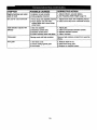
SYMPTOM
POSSIBLE
Depth of cut does not match
depth of scale
1. Indicator not set correctly
2. Knife projection incorrect
90 ° and 45 ° cuts inaccurate
1. Fence stops not adjusted properly 1. Adjust fence stops. See "Adjusting Fence."
2. Fence bottom not even with
2. Clean wood chips from underside of fence.
ouffeed table due to wood chips
under fence
Table elevation adjusts with
difficulty
CAUSE
S)
1. Gibs not adjusted
2. Elevations screws dirty
3. Elevation screws worn
_4.Friction between base and tables
CORRECTIVE
ACTION
11Adjust indicator, securely tighten.
2. See =Adjusting Knife Height," page 10.
1.Adjust gibs.
2. Clean and lubricate elevation screws.
3. Replace elevation screws.
4. Clean, lubricate.
Fuzzy grain
Planing wood with high moisture
Remove high moisture content from wood by
drying.
Torn grain
1. Too heavy a cut
2. Knives cutting against grain
3. Dull knives
1. Reduce depth of cut.
2. Feed work along grain.
15
3. Replace or sharpen knives.
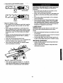
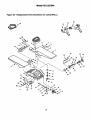
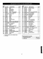
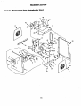
Model 351.227240
Figure 30
Replacement
Parts Illustration
_
for Jointer/Plal,=.
53
52
54
6
7
46
/
4O
\
41
2O
45
42
38
\
6
\
'_ "_"_ 11
10
37
! "_F-_12
34
35
_ "qr._13
_ -,qF.._.14
"_"" 15
2O
t7
26
43
18
25"_"
21
16
23 /
22
21
16
44
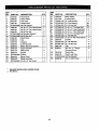
KEY
NO.
PART NO.
DESCRIPTION
1
2929.00
2
3
2930.00
2931.00
2932.00
Base
Infeed Table
Outfeed Table
Wear Plate
4
5
6
KEY
NO.
PART NO.
DESCRIPTION
1
1
29
30
2951.00
2952.00
Plunger Housing
1
1
2
2
31
32
2953.00
2954.00
Spring
Plunger
Scale
1
1
1
33
34
2955.00
STD551137
2956.00
%-24 x 3'/="Hex Head Bolt
3/8"Lock Washer*
2
2
Bearing Housing
6202 Bearing*
Cutterhead
1
1
1
Knife (Set)
Spring
Gib
1
6
3
QTY.
QTY.
2933.00
1395.00
'/,-20 x 1" Wing Screw
'/4-20 x 1" Set Screw
STD541025
2934.00
2748.01
'/4-20 Hex Nut*
Guard
Pointer
6
1
1
36
37
11
12
1286.00
2935.00
2941.00
Rivet
Plate
3
1
1
38
39
40
13
2942.00
1
41
2706.00
Knife Locking Bolt
12
14
15
2943.00
2944.00
STD512505
1
3
2
42
43
!44
8438.00
STD315235
2959.00
5 x 5 x 30mm Key
6203 Bearing*
1
1
2
2
2
45
46
47
2960.00
2961.00
2962.00
Bearing Housing
Drive Pulley
Guide Bracket
Guide Bar
1
1
1
1
4
4
48
49
2817.00
STD551037
4 x 20mm Spring Pin
3/8"Flat Washer*
1
2
4
4
2
50
51
52
STD523712
6555.00
2998.00
3/8-16x 1/,"Hex Head Bolt*
2
53
54
2963.00
92299
4
2
1
%-18 x 3/4"Socket Head Bolt
2
3
3CM-11 E-Ring
Knife Gauge
Rod
Stop Bracket
Knob
1
1
Push Block
Owner's Manual
2
1
7
8
9
10-
16
17
18
19
20
21
STD551025
2945.00
2946.00
STD502503
2947.00
22
23
24
5616.00
STD551131
2948.00
25
2949.00
1390.00
26
27
28
2950.00
2847.00
Spring
Spring Housing
Seat
#8-32 x s/e"Pan Head Screw
'/,-20 x '/="Pan Head Screw*
'/," Flat Washer*
Handwheel
Collar
'/,-20 x %" Set Screw *:
Brass Washer
! s/,6-18x 2" Socket Head Bolt
%" Lockwasher*
Bracket
Elevation Screw
6
5
STD315225
2957.00
92293
9638.0O
2958.00
3155.00
* Standard hardware item available locally
A Not Shown
Recommended Accessories
17
A
HorizontalRollerStand
A
Knife (set)
351.21417
351.2293
_Model 351.227240
Figure 31 - Replacement
Parts Illustration
for Stand
32
16
12
17
42
28
22
fl
ff
I
I
!
I
|
I
|
!
\
2
\
3
!
37
38
18
KEY
NO.
1
2
3
4
5
6
7
PART NO.
DESCRIPTION
2979.00
Front Panel
Strain Relief
2980.00
0615.00
2981.00
STD551006
2982.00
2983.00
8
9
10-
2984.00
STD551208
STD541008
11
12
13
2985.00
2986.00
2987.00
14
15
2988.00
2989.00
16
17
2990.00
2991.00
18
19
20
21
2992.00
STD304320
2993.00
2994.00
22
STD502503
Line Cord
Switch Plate
#6 Flat Washer*
#6-40 x 31,"Pan Head Screw
#8-32 x %" Pan Head Screw
#6-40 Hex Nut
#8 Serrated Washer*
#8-32 Hex Nut*
Back Panel
iKEY
NO.
QTY.
1
2
1
23
1
4
26
27
28
24
25
2
1
2
2
2996.00
STD551037
iSTD541037
1
1
2
37
38
1
1
i39
40
41
42
19
STD541031
STD533105
34
35
36
Motor Mounting Bracket
* Standard Iiardwam
itemavailable locally
...
,
A Not Shown
STD551137
STD551031
STD533107
STD551025
STD512507
2
1
Motor with Key
'/,-20 x %" Set Screw*
Motor Pulley
Locking Stud
%" Lock Washer*
s/,e"Flat Washer*
51,6"-18Hex Nut;
31
32
33
Support
Lower Bracket
1
1
2
2995.00
2717.00
STD523107
STD523110
Top
V-Belt*
Motor Cord
DESCRIPTION
29
3O
2
1
1
Upper Bracket
Side Panel
Guard
PART NO.
5/,6-18x '/="Carriage Bolt*
s/,,-18 x 3/,. Hex Head Bolt*
5/,6-18x 1" Hex Head Bolt*
%-18 x 3/,, Carriage Bolt*
'/," Flat Washer*
V4-20 x 3/4,Pan Head Screw*
Leveler
QTY.
1
3
3
40
30
16
6
4
4
4
4
4
3/£ Flat Washer*
%"-16 Hex Nut*
4
8
2997.00
6366.01
Clip
#8-16 x '/,e"Thread
6
6
061"8.00
Forming Screw
Switch Box
0423.00
STD551008
8438.00
Switch with Key
#8 Flat Washer*
5 x 5 x 30mm Key
1
1
1
1
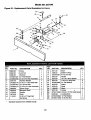
Model 351.227240
Figure 32 - Replacement
Parts Iliustmtion
for Fence
11
16
19
18
17
15
20
\
22
25
KEY
NO.
KEY
NO.
PART NO.
DESCRIPTION
1
1
15
16
2971.00
1329.00
Shaft
1
Trunnion
S/l,"Flat Washer*
1
4
17
18
3CMI-7 E-Ring
3/,'-16 Hex Nut
1
1
Handle
1
5/_6-18x 5/=,Hex Head Bolt*
4
1
19
20
STD541037
2972.00
2973.00
2
4
21
22
10 x 20 x 3mm Spacer
1/,.20 x '/16"Wing Bolt
%" Flat Washer
1
2
2
....
1
1
23
24
25
Guard
Scale
Rivet
1
1
2
2
3
26
27
Pointer
.....
#10-24 x 1/,. Pan Head Screw
1
1
1
28
29
Locking Stud
1/=.Flat Washer
1/="-20Hex Nut
1
1
2
PART NO.
DESCRIPTION
1
2964.00
2
3
2965.00
2966.00
Fence
Lock Nut
4
5
STO551031
STi3523106
2967.00
6
7
8
9
STD523110
STD541031
Trunnion Bracket
s/le-18x 1" Hex Head Bolt*
5/16"-18Hex Nut*
10
11
12
STD523! 17 s/16-18x 13/,"Hex Head Bolt
2968.00
Fence Guide
"Eccentric Shaft
2969.00
Handle
2758.00
13
14
2970.00
1123.01
Knob
1/,-20 x 1/=,Dog Point
Set Screw
_
QTY.
Standard hardware item available locally
2O
2974.00
STD551025
2975.00
2976.00
1286.00
2977.00
STD511002
2978.00
STD551050
STD541150
QTY.
NOTES
21
NOTES
22
NOTES
23
For the repair or replacement
parts you need
delivered directly to your home
Call 7 am - 7 pro, 7 days a week
1-800-366-PART
(1-800-366-7278)
Para ordenar piezas con entrega
domicillo1-800-659-7084
a
For in-home major brand repair service
Call 24 hours a day, 7 days a week
1-800-4-REPAIR
(1-800-473-7247)
Para pedir servicio de reparaci6n
domicillo1-800-659-7084
For the location
a
of a Sears Parts and
Repair Center in your area
Call 24 hours a day, 7 days a week
1-800-488-1222
When requesting service or ordering
parts, always provide the following
information:
•
•
Product Type-Model Number
•
•
Part Number
Part Description
mmmmm
mmmmmm
SEARS
America's Repair Specialists
-m1