1
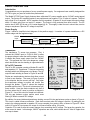
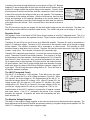
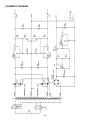
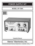
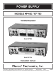
POWER SUPPLY
MODEL XP-720
Instruction Manual
Elenco Electronics, Inc.
Copyright © 1997 Elenco Electronics, Inc.
Revised 2000
REV-A
753270
SPECIFICATIONS ON XP-720 POWER SUPPLY
Input Voltage
Current Protection
110-130VAC
1A
Output Voltage
(at 120V input)
1)
2)
3)
4)
1.5-15VDC @ 1A
1.5-15VDC @ 1A
5VDC @ 3A
6.3, 12.6CTAC @ 1A
Output Regulation
200mV each supply
Line Regulation
100mV each supply
Ripple Max
5mV RMS
Current Protection
1A limit 2-15VDC
3A limit 5VDC
Short Protection
1A limit 2-15VDC
3A limit 5VDC
Output Impedance
.025Ω each supply
CAUTION: The maximum output current for the AC section is 1 amp. Overloading the output or shorting the
6.3VAC to ground will damage the transformer.
OPERATING INSTRUCTIONS
1. Check the voltage rating of the equipment to be powered. Care must be taken not to exceed this rating.
2. Plug the line cord into a 120V 60Hz AC outlet.
3. Adjust the voltage control to desired voltage. Load variation will have practically no effect on the voltage
setting due to the special regulation circuit.
4. Connect the positive lead of your equipment to the red output terminal and the negative lead to the black
terminal when using the positive supplies. For the negative voltage use the yellow terminal.
5. Care must be taken not to exceed the current reading, as the supplies will turn themselves off if overheated.
6. The Model XP-720 has an added feature of having the positive and negative supplies being able to be stacked
to give up to 30V at 1 ampere. Simply use the negative 1.5 to 15V output (yellow jack) as your minus supply
connection. For the positive connection, use the positive 1.5 to 15V red terminal. This will allow you to obtain
a variable 3V to 30V at up to 1 ampere out.
-1-
CIRCUIT DESCRIPTION
Introduction
Congratulations on your purchase of a very versatile power supply. Our engineers have carefully designed the
XP-720 to give you years of trouble-free performance.
The Model XP-720 Power Supply features three solid-state DC power supplies and a 12.6VAC center tapped
output. The first two DC supplies consist of one positive and one negative 1.5 to 15 volts at 1 ampere. The third
has a fixed 5V at 3 amperes. All DC supplies are fully regulated. A special IC circuit keeps the output voltage
within .2V when going from no load to 1 ampere. The output is fully protected from short circuits. The AC
section has 6.3VAC @ 1A and a 12.6 center tapped @ 1A. This supply is ideal for use in school labs, service
shops or anywhere a precise DC voltage is required.
Power Supply
Figure 1 shows a simplified circuit diagram of the positive supply. It consists of a power transformer, a DC
rectifier stage and the regulator stage.
120VAC
Input
Transformer
120V to 17V
17VAC
20VDC
AC to DC
Converter
Voltage
Regulator
Simplified diagram of positive power supply
1.25 - 15V
Regulated
Output
Figure 1
Transformer
The transformer T1 serves two purposes. First, it
reduces the 120VAC input to 17VAC to 8VAC to allow
the proper voltage to enter the rectifier stages. Second,
it isolates the power supply output from the 120VAC
line. This prevents the user from dangerous voltage
shock should the user be standing in a grounded area.
Voltage Waveform for Supply
A) Transformer
Winding AB
AC to DC Converter
B) Transformer
Winding BC
The AC to DC converter consists of diodes D1 and D3
and capacitor C5. Transformer T1 has two secondary
windings which are 180 degrees out of phase. The AC
output at each winding is shown in Figure 2A and 2B.
C) Output of
diode D1.
D) Output of
diode D2.
Diodes are semiconductor devices that allow current
to flow in one direction. The arrow in Figure 3 points
to the direction that the current will flow. Only when
the transformer voltage is positive will current flow
through the diodes. Figure 3 shows the simplest
possible rectifier circuit. This circuit is known as a halfwave rectifier. Here the diode conducts only half of
the time when the AC wave is positive as shown in
Figure 2C. Use of this circuit is simple but inefficient.
The big gap between cycles require much more
filtering to obtain a smooth DC voltage.
Half Wave Rectifier
Figure 3
E) Total of diodes
D1 & D2.
20V
F) Output of capacitor C1
Ripple depends on load
current (expanded).
Figure 2
Full Wave Rectifier
Figure 4
By addition of a second diode and transformer winding, we can fill in the gap between cycles as shown in Figure 4.
This circuit is called full-wave rectification. Each diode conducts when the voltage is positive. By adding the two
outputs, the voltage presented to capacitor C5 is more complete, thus easier to filter, as shown in Figure 2E. When
used in 60 cycles AC input power, the output of a full wave rectifier will be 120 cycles.
Capacitor C5 is used to store the current charges, thus smoothing the DC voltage. The larger the capacitor, the
more current is stored. In this design, 2200µF capacitors are used, which allows about 3 volts AC ripple when
one amp is drawn.
-2-
In practice, the current through the diodes is not as shown in Figure 2C. Because
capacitor C5 has a charge after the first cycle, the diode will not conduct until the
positive AC voltage exceeds the positive charge in the capacitor. Figure 5 shows
a better picture of what the current flow looks like, assuming no loss in the diode.
It takes a few cycles for the voltage to build up on the capacitor. This depends on
the resistance of the winding and diode. After the initial start-up, there will be a
charge and discharge on the capacitor depending on the current drawn by the
output load. Remember current only flows through the diode when the anode is
more positive than the cathode. Thus, current will flow in short bursts as shown in
Figure 5C.
A) Transformer
Winding
20V
Peak
B) Voltage C1
20V
C) Current
through diodes
Figure 5
The DC load current may be one ampere, but the peak diode current may be three times that. Therefore, the
diode rating must be sufficient to handle the peak current. The 1N4001 has peak current rating of 10 amps.
Regulator Circuit
The regulator circuit in the Model XP-720 Power Supply consists of a LM-317 integrated circuit. This IC is
specially designed to perform the regulation function. Figure 6 shows a simplified circuit of how the LM-317 IC
works.
Transistors Q1 and Q2 form a circuit known as a differential amplifier. Transistor Q1 base is connected to a
stable 1.5V reference voltage. The base of Q2 is connected to the regulator output circuit through a voltage
divider network. The collector of transistor Q2 is connected to a current source. This basically is a PNP
transistor biased to draw about 1mA of current. Transistor Q2 sees the current source as a very high resistor
of about 1 meg ohms. Thus, the gain of transistor Q2 is extremely high.
Transistor Q5 is called the pass transistor. It controls the current reaching the
output. Transistors Q3 and Q4 are emitter followers. Their function is to raise
the impedance of the pass transistor. Note that transistors Q2, Q3, Q4 and Q5
and resistor R1 form a close loop. Also, note that the feedback to the base of
Q2 is negative, that is, when the base of Q2 goes positive, the output at emitter
Q5 goes negative. Now if the 2V output voltage goes down because of current
drain at the output, the base of Q2 will drop forcing the collector voltage of Q2
to go higher. This will bring the output voltage back to 2V. This is the basis of
all negative feedback regulators.
Current
Source
Equalized
to 1 Meg.
2V
Output
Q5
Q3
R1
Q4
Q2
1.5V
R2
Q1
Divider
Figure 6
The LM-317 Integrated Circuit
The LM-317 IC is basically a 1.25V regulator. To be able to vary the output
1.25 - 15V, we stack the IC on a DC voltage as shown in Figure 6A. When
VR1 equals 0, the output voltage is 1.25V as determined by the LM-317 IC.
Note that the voltage across R1 is always 1.25V. When R1 equals VR1, the
voltage across VR1 will equal the 1.25V across R1, therefore, the output
voltage will be 2.5V. When VR1 is 5 times R1, the output voltage is 6.25V. As
you can see, varying resistor VR1 will vary the voltage from 1.25V to 15V.
Another feature of the LM-317 regulator is to protect the IC against overload
and output shorts. If the IC is overloaded, the junction of an overload
transistor will overheat. A transistor will sense this overheating and shut
down transistor Q5.
LM-317
1.25 - 15V
R1
VR1
Figure 6A
The Negative Voltage Regulator
The theory of the negative voltage regulator is the same as the previously discussed positive regulator. The
basic differences is that diodes D2 and D4 are reversed, producing a negative voltage across capacitor C6. The
LM-317 IC is designed to operate from a negative supply.
-3-
The 5 Volt Power Supply
In the previous discussion of the variable voltage regulators, the ICs can handle about 1A of current. In the
design of the 5V supply, we need 3A of current. To meet this current requirement, we must add an external pass
transistor capable of delivering 3A.
Figure 7 shows a simplified 5V regulator with an external PNP pass
transistor. In this circuit, transistor Q1 is a power transistor capable of
delivering over 3A. Transistor Q2 is biased off until the LM-7805 IC
draws about .2A. When .2A is drawn by the LM-7805 IC, the voltage
drop across the 3 ohm resistor is .6V, enough to turn on transistor Q2.
Transistor Q2 takes over and delivers the current to the output. Note that
if the output voltage goes down, the LM-7805 regulator will draw more
current, forcing the output voltage back to 5V. Thus, the LM-7805
regulator controls the output voltage and keeps it at 5V.
Figure 7
Unfortunately, this circuit has no control of the output maximum current. If the output is shorted to ground
transistor Q2 will be overloaded and eventually be damaged. The LM-7805 IC will only draw the .2A it was
designed to handle and never heat up to turn itself off. Another transistor, Q1, is added to limit maximum current.
Resistor R5 is added to sense the current in transistor Q2. When approximately 3A is drawn in transistor Q2,
the voltage drop in resistor R5 will turn on transistor Q1. This will force more current in the LM-7805 IC.
Eventually the LM-7805 IC will overheat turning itself off and thus limiting the circuit at about 2.6A.
The first .2A of current is drawn by the LM-7805 IC. The next 3A are drawn by transistor Q2. Thereafter, the
current is drawn by the LM-7805 IC until it overheats and turns itself off. This is a very effective circuit capable
of regulating the output voltage at a constant 5 volts and yet delivering over 3A of current.
AC Power Supply
The section features a 12.6VAC center tapped output. Two secondary windings from the transformer are
connect directly to the yellow binding posts. Connecting from one of the outputs to the center black binding post
will give you 6.3VAC. The maximum output current for 12.6VAC and 6.3VAC is 1A.
This concludes the discussion on the operation of the XP-720 Power Supply.
WARRANTY POLICY
Your power supply has been tested and conforms to our rigid requirements on performance and durability. It is guaranteed to be free of
defects in workmanship, materials and construction for a period of 2 years. If this product should fail during normal use within the first 3
months from the date of purchase, Elenco will repair or replace the unit at no cost. For the remainder of the warranty period, a nominal
service charge is required to cover shipping and handling.
When returning merchandise for repair, please include proof of purchase, a brief letter of explanation of problem and sufficient packing
material. Before returning any merchandise, please call our service department at (847) 541-3800 to obtain a return authorization
number (RA).
Elenco Electronics, Inc. Service Department
150 W. Carpenter Avenue Wheeling, IL 60090
-4-
PARTS LIST
QTY
1
2
2
2
DESCRIPTION
RESISTORS
.18Ω 3W
2.7Ω 1/2W (red-violet-gold-gold)
180Ω 1/4W (brn-gray-brn-gold)
2kΩ Potentiometer
PART #
5
2
1
CAPACITORS
10µF Electrolytic
2,200µF Electrolytic
4,700µF Electrolytic
271045
292226
294744
4
4
1
1
1
1
1
SEMICONDUCTORS
1N4001 Diode
1N5400 Diode
MPSA70 Transistor
2N6124 Transistor
LM-317 IC
LM-337 IC
LM-7805 IC
314001
315400
320070
326124
330317
330337
337805
1
1
1
1
1
1
1
2
MISCELLANEOUS
Transformer
PC Board
Fuse 1A
Rocker Switch
Cover
Chassis
Heat Sink
Knob
440720
512013
530100
541204
611120
612012
615010
622009
QTY
1
5
4
2
7
7
2
3
3
5
2
4
2
2
1
4
2
2
2
3
1
4
1
1
1
1
3
1
101804
112701
131800
192422
-5-
DESCRIPTION
Strain Relief
Bushing
PC Board Stand-off
Black Binding Post
Lockwasher
Nut
Red Binding Post
Yellow Binding Post
Cable Ties
Screw 6-32 x 3/8”
Screw 8-32 x 3/8”
Screw 6 x 3/8” black
Screw 6 x 3/8” black
Nut 7mm
Nut 6-32
Nut 6-32 small
Nut 8-32
Flat Washer 8mm x 14mm
Lockwasher 5/16”
Lockwasher #8
Solder Lug #8
Rubber Feet
Fuse Holder (lower body)
Fuse Holder (nut)
Fuse Holder (upper body)
Fuse Holder (washer)
Mica Insulator
Line Cord
PART #
624003
624007
625002
625031
625031LW
625031HN
625032
625034
628982
641640
641840
642652
642660
644101
644600
644601
644800
645101
646101
646828
661002
662001
663005LB
663005N
663005UB
663005W
780002
862105
SCHEMATIC DIAGRAM
-6-
Elenco Electronics, Inc.
150 W. Carpenter Avenue
Wheeling, IL 60090
(847) 541-3800
http://www.elenco.com
e-mail: [email protected]