1
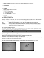
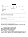
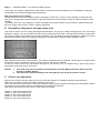
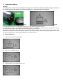
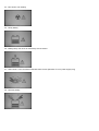
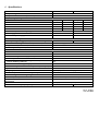
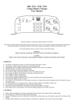
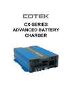
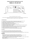
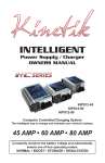
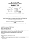
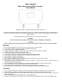
SBC-9138/9238
Multi- Stage Smart Battery Chargers
User Manual
Keep this manual in a safe place for quick reference at all times.
This manual contains important safety and operation instructions for correct use of the battery charger. Read through the
manual and pay special attention to the markings and labels of the charger, battery and equipment connected to the
battery system.
Pay special attention to these two types of notices used in this manual.
WARNING:
Failure to heed this warning may cause injury to persons and damage to Equipment.
CAUTION:
Failure to observe this warning may result in damage to equipment and improper functioning of the Charger.
WARNING:
●
●
●
●
●
●
●
●
●
●
●
●
●
●
●
●
●
The charger is designed for in-door use. Protect the charger from ingress of water.
This charger is made to charge only properly sized lead acid batteries.
Don't recharging non-rechargeable batteries.
Charging other types of battery or under-sized lead acid batteries may cause fire or explosion.
Install the charger in accordance with all local codes
Do not use the charger if it has been dropped or damaged.
Do not remove casing of the charger, there is no user-serviceable parts inside.
Do not charge the battery on boats. Remove the battery and charge on shore.
Never attempt to charge a frozen battery
Never attempt to charge a damaged battery.
Wear protective goggles and turn your face away when connecting or disconnecting the battery.
Never place the charger on top of a battery.
Never smoke, use an open flame, or create sparks near battery or charger during normal charging operation as
batteries may give out explosive gas.
Do not charge batteries in an enclosure (box- in) due to possible explosion of entrapped explosive gas.
Use of accessory not recommended may cause risk of fire, electric shock.
Disconnect the mains supply before connecting or disconnecting the links to the battery.
If the charger does not work properly or if it has been damaged, unplug its AC and DC connection.
CAUTIONS:
●
●
●
●
●
Refer to battery manufacturer’s specific recommended values for battery type settings and float voltage setting.
Fix the charger to a solid support via three grooves at the flange of chassis, with three screws or nuts.
Ensure all ventilation ports are not obstructed for efficient fan cooling, keep loose soft material or paper off at the vent
holes of the charger.
During charging, the battery must be placed in a well ventilated area.
If longer output charging cord is required, make sure the diameter is adequate for the current in given cable length.
INTRODUCTION
Congratulations on purchasing our new Multi-Stage (IU0U) Switching Mode Smart Battery Charger.
This software based MCU control 7 stage smart charger is designed with user friendly features and software plus
hardware protection. It is a set, connect and forget charger that ensures complete recharge of your battery.
Your battery can be connected indefinitely to the charger which will enter into energy conservation mode to prevent over
charging and save electricity bills. The battery state of charge and temperature are closely monitored, updated and
logged by the MCU and the remote temperature sensor mounted on the supplied charger cable and heavy duty battery
clamps.
Though the charger basically is engineered to charge high capacity battery/ banks, it can be made to charge much
smaller battery by selecting the right reduced output setting. This charger can also be converted to a fixed voltage power
supply with one simple concealed which setting.
The extensive protection with alarm and LED indications including the thermostatic decrease of charging current to shut
down ensure a durable working life span even in harsh conditions for the charger and the battery. There are selections for
WET, AGM, GEL and Calcium-Calcium battery types. Special evaluation, conditioning charging profiles are made for the
WET type battery so to recover deeply discharged WET lead acid battery.
There is a Power Supply (PS) mode to provide a constant voltage DC power 13.3V to the external load connected to the
battery and at the same time without over charging the battery.
Almost all the protections are controlled by the Micro-Processor. On start up, the chargers run a series of self tests on the
protective functions, displays and critical components like the cooling fan.
Intended Use:
All Automotive, Marine, Mobile Home, Electric Scooters, Golf Carts, Solar, Deep Cycle, UPS Standby, Industrial &
Commercial Applications.
A. Control and Indicators
Fig.1
1.
Charger status LCD display
Display the charging status, charging voltage/ current, battery type selected and etc.
Details please see this section below.
2.
Programming Port
Factory use only
3.
Recondition mode switch
Simple press and hold 3 seconds the switch to set the charger to go with recondition charge in next cycle.
4.
Battery selection switch
For Wet, AGM, GEL, Calcium-Calcium and Power supply mode. (Default at position 3 the GEL type)
5.
Charging current selection switch (Manual de-rating)
Current can be selected to 20%, 40%, 60%, 80% and 100% of the max current. Details please see the label
under the moveable door. (Default at 100%)
6.
Back Light ON/OFF switch (Only for SBC-9138/9238)
Toggle ON/OFF the backlight by pushing the removable door, no need to open the door.
Press x 1 : Backlight ON for 5 minutes
Press x 2 : Backlight always ON
Press x 3 : To turn backlight OFF
7.
Charging cable with removable temperature sensor
RED battery clamp– Battery positive pole
BLACK battery clamp– Battery negative pole
8.
Removable temperature sensor
To increase/ decrease charging voltage at low/ high battery temperature
9.
Ventilation Fan
Thermostatic control fan from zero to full speed
10. AC input power cord
LCD Display Indication
a.
Charging status curve
To show the battery charging status
DES: Desulphation charge (charging with pulse charge)
SST: Soft start (charging with 1/2 the max current)
BUL: Bulk charge (charging with constant max. current)
ABS: Absorption (charging with preset constant voltage)
REC: Recondition charge (for WET battery type only)
FLO: Float charge (charging with preset constant voltage)
STA: Standby (charging with 96% of the preset constant float voltage)
b.
Voltmeter
Displays the charging voltage
c.
Ammeter
Displays the charging current
d.
Battery type
Displays the battery type selected
e.
Power level meter
Displays current power level (the % of output current selected, details please see section F)
f.
Charging status
NORMAL: Charging with normal profile
RECOND: Charging with Recondition mode
g.
AH meter
Displays total AH value for the charging
h.
Backlight status
To show the backlight status
BL. ON: Backlight always ON
BL. T: Backlight will ON for 5 minutes
BL. OFF: Backlight OFF
i.
Run timer
Displays unit total run-time
B. Battery Type Selection
Make sure the charger is power OFF, use a small slot type screw driver to select the battery through Battery Selection
Switch (4). Please refer to the label under the removable door for battery type selection list
The LCD will display the battery type you selected after restart the charger.
WET
AGM/GEL
Calcium-Calcium
Power Supply
:
:
:
:
Flooded Type lead acid batteries (to which water can be added) Automotive or Deep Cycle
Sealed type (VRLA), AGM-GEL, Maintenance Free, Automotive or Deep Cycle lead acid batteries
Sealed type (VRLA) Lead Acid batteries with Calcium content Automotive or Deep Cycle
to provide a constant voltage DC power 13.3V to the external load connected to the battery and at
the same time without over charging the battery
B1. Recommended Battery Capacity
The following minimum AH capacities are a generalized suggestion, some batteries can take higher charge current,
check with battery manufacturers for charging batteries with smaller capacity.
Charger Model
Battery Capacity
SBC-9138 , 12V/25A
20 AH - 250 AH
SBC-9238 , 24V/13A
10 AH - 125 AH
C. Battery Charger Installation and Connection
Observe the warnings & safety precautions before rushing to install and operate the charger.
Check battery condition, fill up cells for wet battery, clean battery poles.
Secure the battery charger in a well ventilated place, make sure the mounting surface is flat and without soft covering
material or loose paper sheet. The air intake is at the left side and air outlet at the right side. Make sure both intake and
outlet are not blocked. Never place charger on top of battery.
Plug in the AC mains. The LCD will display “Welcome” and unit software version and then go through a self-test.
The cooling fan spins at full speed for 3 seconds and a “Beep” sound by means of Self-Testing.
Figure to show charger initial
Figure to show internal DC fan is under checking
Once Self-Testing completed, the LCD display will show as below and remind you the charger are ready for battery
connection.
Once battery connected, the LCD display will show as below and the charger will start to check battery status for 5
seconds before start charging.
Before connecting or disconnecting the charging cable, unplug AC cord from the mains.
First connect the Red battery clamp to the battery Positive + Pole. Then connect the Black battery clamp to the
Negative – Pole of the battery.
Make sure all the connections are secured, double check on the correct polarity.
Double check again for correct selection of Battery Selection Switch (4) for battery type (default at GEL) and Charging
Current Selection Switch (5) for output current setting (default at 100%)
When install in caravans and similar vehicles, the connection to the supply mains is to be in accordance with national
wiring rules.
When charging automotive batteries:
The battery terminal not connected to the chassis has to be connected first. The other connection is to be made to
the chassis, remote from the battery and fuel line. The battery charger is then to be connected to the supply mains;
After charging, disconnect the battery charger from the supply mains. Then remove the chassis connection and then
the battery connection.
Please notice the tightness of the power cables battery clamps to the load. If the cables are not secured well
enough, the total resistance of the connecting cables will increase, resulting in a huge voltage drop between the
battery charger to the load.
D. Normal Multi-Stage (IUoU) Charging Operation
The 7-stage IU0U charge algorithm ensures fast, complete and at the same time gentle charging of the lead acid battery.
Charging Profile
Stage 1.
DESULPHATION charge - The pulse charging
If the initial battery voltage is less than 9V, the charger will start Desulphation mode with pulse charge profile. The
desulphation curve (DES) will display with slow flashing.
Stage 2.
SOFT START - The constant current charging
If at the initial bulk charging, the battery voltage is still less than 11V due to deep discharge, the charger will go with soft
charge. The soft start curve (SST) will display with slow flashing. The bulk charging current is reduced to half of the
maximum current until battery voltage rises over the set limit 11V at which point the charger switches to Bulk charge.
In case the battery voltage cannot pass the voltage limit within 2 hours, the charger switches to fault mode and
discontinues the charging.
Stage 3.
BULK CHARGE - The constant current charging
Normally the battery is charged at constant maximum current until it rises to the selected Absorption voltage level.
The charging voltage changes with the battery voltage. The Bulk curve (BUL) will display with slow flashing.
If the charger cannot go to Absorption mode within 20 hours, the charger will automatically goes to Float mode so to
prevent over charge the battery. This is call safety timer
Stage 4.
ABSORPTION CHARGE - The constant voltage charging
Battery Type Selection: Wet: 14.4V, AGM: 14.3V, Gel: 14.1V, Calcium: 15.1V
When the battery voltage rises to the selected Absorption voltage level, the charging will switch to Constant voltage
charging. The Absorption curve (ABS) will display with slow flashing. Absorption charging current will decrease gradually
to a set value at which the charger automatically switches to Float Stage.
The max. absorption time is also controlled by the time in Bulk charge and battery type selected.
Remark: There is no charging at the end of Absorption charge.
This is normal as the battery you connected is under analysis.
Stage 5.
RECONDITION CHARGE - The constant voltage charging
Only for WET battery and manual select, please refer to section E.
Stage 6.
FLOAT CHARGE - The constant voltage charging
In this stage, the battery is full and only takes in the amount of current necessary for maintaining the capacity. The float
voltage is preset by factory according to the type of battery. The Float curve (FLO) will display with slow flashing.
In case of the charger keeps at this mode with charging current less than 20% of bulk current for over 60 hours. The
charger will go into the Standby mode.
Stage 7.
STANDBY MODE - The constant voltage charging
In this stage, the charging voltage at this mode will be 4% less than the Float voltage only for maintaining the capacity.
The Standby curve (STA) will display with slow flashing.
New Cycle Charge every 18 days
Charger will start a new cycle charging of bulk to absorption to float every 18 days in either standby or float mode This
new cycle of charging will refresh the battery to prevent separation of the electrolyte & keep the electrode plates in good
condition.
The standby auto new cycle charge per 18 days are designed to keep the battery in good working condition during long
period of resting of the caravan or back up battery application.
E. Recondition Charging for wet type battery only
This mode is used to recover deeply discharged flooded battery only by high voltage charging (about 10% overcharge
absorption voltage). You can manual select this mode by simply press and hold 3 seconds the Recondition mode switch
(3) to set the charger at the beginning of charging operation. The LCD display will show RECOND to represent you have
selected Recondition mode in this charging cycle and the charging will be conducted after Absorption mode.
After entered into this mode, the Recondition curve (REC) will display with slow flashing. This will put the charger keep at
Recondition mode for preset time and then charger will go to Float once completed.
In case you want to cancel the Recondition charge that you selected, you can disable this by press and hold the
Recondition mode switch (3) for 3 seconds.
Remark: 1.
2.
This mode only can be operated at Flooded battery selected (Battery Selection Switch (4) set to
position 1 the WET battery)
Take special precautions as battery will emit explosive gas during Recondition charge.
F. Power Level adjustment
End user can set the maximum output current so to make the charger can suitable for different capacity battery
Make sure the charger is power OFF before adjust the power level.
Use a small slot type screw driver to select the maximum output current through the Charging Current Selection Switch
(5). Please refer to the label under the removable door for power level selection.
LCD display will show the power level by % after restart the charger.
Position 1: 100% of the rated current
Position 2: 80% of the rated current
Position 3: 60% of the rated current
Position 4: 40% of the rated current
Position 5: 20% of the rated current
G. Temperature Sensor
Warning!
The temperature sensor must be installed at the Negative Terminal of the battery terminal, wrong connection to
the Positive Terminal will damage the charger and the sensor. See below Fig.5 for installation.
Fig.5
Fig.6
The temperature sensor is used to optimal charging over wide ambient temperature range.
Fix the temperature sensor in a position on the battery which is not affected by other cooling or heating source. Or you
can insert it into the power cable negative battery clamp (factory pre-mounted)
The reference temperature of this sensor is 25°C and compensation voltage is -20mV/°C for SBC-9138 and -40mV/°C for
SBC-9238, the higher the battery temperature, the lower the charging voltage. When battery temperature reaches 60°C,
the charger will shutdown. LCD will display Battery OTP symbol as Fig.6.
H. Fault Indication
F1: Charger over temperature protection
F2: Output over voltage (tracking)
F3: Overload (OCP), 10% higher than the C.C.
F4: Fan stuck or not working
F5: Faulty battery
F6: Battery temp over 60°C as detected by remote sensor
F7: short circuit > 5 sec shut down otherwise auto-recover (Remark: F7 is for power supply only)
F8: Reverse polarity
I.
Trouble Shooting
PROBLEM
INDICATIONS
POSSIBLE CAUSES
SUGGESTED SOLUTION
Charger does not
work
LCD display not
turn on
No AC power
Check AC connections are correct
AC input socket fuse blown
Replace with correct AC fuse by
qualified electrician
No DC output
Battery does not
get full charge
Output short circuit Output short circuit
symbol displays
Check DC connections between
charger and battery. Charger can auto
reset if remove the fault within 20
seconds.
Charger over
temperature
symbol displays
Over temperature protection triggered
Check air intake vent at bottom of
charger is blocked or not. Check
charger ambient ventilation.
Overload (OCP)
symbol displays
Severe over loading charger
Check battery AH capacity within
recommended range
Reverse polarity
symbol displays
Reverse polarity connection
Check for correct polarity
Fan stuck symbol
displays
DC fan locked by foreign object or
malfunction
Check DC fan
LCD displays work Bad battery connection
normally and
sequentially
Battery type select switch in wrong
setting
Check for loose contact, right cable
size, cable integrity
Recheck battery type and change to
correct battery selection
Battery capacity too large
Make sure charger rating matches
battery capacity
Ambient temperature too low
Move battery to a room temperature
location, or get an optional
temperature sensor
Battery has damaged cell or battery is Replace battery
too old
Wrong set the lower power level
Long charging
time, float curve
does not come on
even after 20
hours charging
time.
Absorption curve
Charger internal fault
remains display all
the time
Bulk curve is
Bulk curve
display all the time remains on all the
time
Recheck the current selection switch
(5) to correct right setting
Return the charger to distributor to
repair
Wrong battery type selection
Check charged battery label and
change battery type selection to
correct setting
Battery is excessively depleted and
the soft charging is triggered
Recharge the battery after a day, if
bulk light remains after several hours,
the battery is most likely damaged and
cannot accept charge. Replace
battery.
Battery temperature too high
Use accessory temperature sensor
J. Specifications
Model
SBC-9138
AC Input Voltage 200-240VAC, 50Hz~
Yes
AC Input Current at Full Load (at 230VAC)
2.9A
SBC-9238
Output (Charge) Voltage Selections
Absorption
Float
Absorption
Float
WET
14.4V
13.5V
28.8V
27.0V
AGM
14.3V
13.2V
28.6V
26.4V
GEL
14.1V
13.7V
28.2V
27.4V
CALCIUM
15.1V
13.8V
30.2V
27.6V
Recondition (for WET Battery only)
15.9V / 3A
31.8V / 3A
Power Supply Mode
13.3V
26.6V
Maximum Output Charging Current
25A
13A
Battery Voltage to Trigger (cut-in) Soft Start Bulk Charge Mode
<11V
<22V
Soft Start Bulk Charge Current Level (current limit)
1/2 of the charging current
Ripple & Noise (Peak to Peak)
<200mV
Efficiency at WET (230VAC)
>85%
Soft Start Bulk Charge
Protections
Short Circuit Protection
Yes
Overload Protection
Yes
Reverse Polarity Protection (by Mosfet)
Yes
Over Temperature Protection
OVP (Output Tracking Over Voltage Protection)
(can be disable by end user)
Thermal decrease of charger output power
Yes
Thermostatically Controlled Variable Speed Fan (0-full speed)
Yes
Approvals
CE
Charge Cycle, Protection Indication
LCD display indication for charging status, mode and fault
Build in Temperature Sensor in Battery Clamp
Yes
Plastic Housing with Mounting Flange
Yes
Dimension (WxHxD)
220 x 80 x 140mm (8.7 x 3.2 x 5.5inch)
Weight
2kgs (4.4Lbs)
Accessories
Charging Cable with Battery Clamp
Recommended Battery Capacity Range
20AH to 250AH
Yes
Yes
EN 60335 ; EN 55014 ; EN 62233
10AH to 125AH
Rev.0 09/2013
7673-9138-0000