1
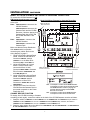
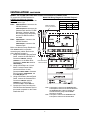
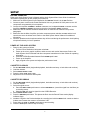
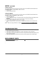
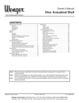
Owner’s Manual
Audio System CD/RW Upgrade Kit
Tascam CC-222 CD/RW Recorder/Cassette Deck — cables are supplied but not shown
CONTENTS
Warranty . . . . . . . . . . . . . . . . . . . . . . . . . . . . . . . . . . . . . . . . . . . . . . . . . . . . . . . . . . . . . . . . . . . . . . . . .2
Manufacturer’s Owner Manuals . . . . . . . . . . . . . . . . . . . . . . . . . . . . . . . . . . . . . . . . . . . . . . . . . . . . . . .2
Installation . . . . . . . . . . . . . . . . . . . . . . . . . . . . . . . . . . . . . . . . . . . . . . . . . . . . . . . . . . . . . . . . . . . . . . . .2
Before Starting Installation . . . . . . . . . . . . . . . . . . . . . . . . . . . . . . . . . . . . . . . . . . . . . . . . . . . . . . .2
Install the CD-RW Recorder Cassette Deck . . . . . . . . . . . . . . . . . . . . . . . . . . . . . . . . . . . . . . . . . .2
Series 200 and 300 CD-RW Playback and Cassette Recording Connections . . . . . . . . . . . . . . . .3
Series 200 and 300 CD-RW Record and Cassette Playback Connections . . . . . . . . . . . . . . . . . .4
Change Record Function . . . . . . . . . . . . . . . . . . . . . . . . . . . . . . . . . . . . . . . . . . . . . . . . . . . . . . . .4
Model 402 CD-RW Playback and Cassette Recording Connections . . . . . . . . . . . . . . . . . . . . . . .5
Change Record Function . . . . . . . . . . . . . . . . . . . . . . . . . . . . . . . . . . . . . . . . . . . . . . . . . . . . . . . .5
Model 402 CD-RW Record and Cassette Playback Connections . . . . . . . . . . . . . . . . . . . . . . . . .6
Change Record Function . . . . . . . . . . . . . . . . . . . . . . . . . . . . . . . . . . . . . . . . . . . . . . . . . . . . . . . .7
Model 502 CD-RW Playback and Cassette Recording Connections . . . . . . . . . . . . . . . . . . . . . . .7
Model 502 CD-RW Record and Cassette Playback Connections . . . . . . . . . . . . . . . . . . . . . . . . .8
Setup . . . . . . . . . . . . . . . . . . . . . . . . . . . . . . . . . . . . . . . . . . . . . . . . . . . . . . . . . . . . . . . . . . . . . . . . . . . .9
Power Up the Audio System . . . . . . . . . . . . . . . . . . . . . . . . . . . . . . . . . . . . . . . . . . . . . . . . . . . . . .9
Cassette Playback . . . . . . . . . . . . . . . . . . . . . . . . . . . . . . . . . . . . . . . . . . . . . . . . . . . . . . . . . . . . .9
Cassette Recording . . . . . . . . . . . . . . . . . . . . . . . . . . . . . . . . . . . . . . . . . . . . . . . . . . . . . . . . . . . . .9
CD/RW Playback . . . . . . . . . . . . . . . . . . . . . . . . . . . . . . . . . . . . . . . . . . . . . . . . . . . . . . . . . . . . . . .10
CD/RW Recording . . . . . . . . . . . . . . . . . . . . . . . . . . . . . . . . . . . . . . . . . . . . . . . . . . . . . . . . . . . . . .10
Troubleshooting . . . . . . . . . . . . . . . . . . . . . . . . . . . . . . . . . . . . . . . . . . . . . . . . . . . . . . . . . . . . . . . . . . . .10
Replacement Parts . . . . . . . . . . . . . . . . . . . . . . . . . . . . . . . . . . . . . . . . . . . . . . . . . . . . . . . . . . . . . . . . .10
Thank you for purchasing a Wenger Audio System CD/RW Upgrade Kit. This document serves as a
quick start guide. The instructions and illustrations in this document apply to the Audio System CD
Upgrade for Series 200, Series 300, Series 400, and Series 500 Audio Systems. Please refer to
each manufacturer’s owner’s manual for additional information. Please contact Wenger Corporation
Customer Service with any questions at 1-800-887-7145.
©Wenger Corporation 2004
Printed in USA06/04
Part #126C937-2
Wenger Corporation, 555 Park Drive, P.O. Box 448, Owatonna, Minnesota 55060-0448
Questions? Call.....USA: (800) 733-0393 • International (call collect): (507) 455-4100 • www.wengercorp.com
WARRANTY
Wenger Corporation will act as a contact and provide support for the Audio System CD/RW Upgrade Kit.
Call Wenger Corporation Customer Service with any questions or problems at 1-800-887-7145. While
Wenger Corporation will coordinate customer service with the component manufacturer, the
manufacturer of the Audio System CD/RW Upgrade KIt component is responsible for that component
warranty. There is a manufacturer’s warranty card accompanying this manual. It is important to fill out
this warranty card and register it with the manufacturer within 30 days after receipt of the system.
The warranty for the component is as follows:
Component
Warranty
Tascam CC-222 CD/RW Recorder/Cassette Deck
1 Year
MANUFACTURER’S OWNER MANUALS
The following manufacturer’s owner manual is contained in the shipping container.
• TASCAM CC-222 CD Recorder/Cassette Deck Owner’s Manual
INSTALLATION
BEFORE STARTING INSTALLATION
1. Insert this manual and the manufacturer’s Owner’s Manual (included in the shipping carton) into the
Audio System Binder that came with the Audio System.
2. Please read and understand this entire document.
3. Refer to the illustrations on the following pages. If you need additional information about your Audio
System CD/RW Upgrade Kit, write, telephone, or email Wenger Corporation.
4. Refer to the Manufacturer’s documentation for addition operation information.
5. Fill out the Tascam CC-222 CD/RW Recorder/Cassette Deck warranty card with the appropriate
serial number and mail to the Manufacturer. This warranty card must be registered with the
manufacturer within 30 days of receipt of the CD/RW Upgrade KIt.
6. Before starting the installation, disconnect power from the Audio System Power Distribution Unit
(remove the power cord from the 120VAC power source).
INSTALL THE CD-RW RECORDER CASSETTE DECK
Refer to the Connection Diagrams on pages 3 to 5 showing the finished position of the CD/RW
Recorder/Cassette Deck deck and how it is connects to the Audio System.
1. Remove the Screws that attach the Rack Shelf to the Audio System Rack. Set aside the Rack Shelf
and the Screws.
2. Insert the CD/RW Recorder/Cassette Deck into the Rack in
Power Distribution Unit
place of the Rack Shelf (just below the Power Distribution
Unit).
3. Attach the CD/RW Recorder/Cassette Deck to the Rack with
four Screws (10-32x3/4") set aside in step 1.
Typical Rack Shelf
2
INSTALLATION
CONTINUED
SERIES 200 AND 300 CD-RW PLAYBACK AND CASSETTE RECORDING CONNECTIONS
To connect the CD-RW/Cassette for CD-RW playback and Cassette recording, do the following. Refer
to the illustration at the right.
Note: LINE OUTPUTS 1 connect to the
CD-RW Recorder.
LINE OUTPUTS 2 connect to the
Cassette Deck and the CD-RW
Model 202/302 Wiring Diagram for Cassette Recording
Recorder. If both are playing,
the Cassette Deck has priority
Function
and the CD-RW Recorder is
Device
Playback Record
not heard.
CD/RW
Note: LINE INPUTS 1 connect to the
Cassette
CD-RW Recorder.
LINE INPUTS 2 connect to the
Cassette Deck
1. Using a RCA/Phono to 1/4-inch
Internal Patch Cable, connect the
CD-RW RCA Connector LINEOUT 1
R and LINEOUT 1 L to the Mixer
1/4-inch Connector STEREO 1 R
and STEREO 1 L.
2. Using a RCA/Phono Internal Patch
Cable, connect the Mixer RCA
Connector REC OUT R and REC
OUT L to Cassette RCA Connector
LINE INPUTS 2 R and LINE INPUTS 2
L.
3. Using a RCA/Phono Internal Patch
Cable, connect the Cassette RCA
Connector LINEOUT 2 R and
LINEOUT 2 L to Mixer RCA
Connector PLAYBACK IN R and
PLAYBACK IN L.
4. Connect the Power Cord from the
CD-RW Recorder/Cassette Deck to
Cable with RCA to
an unused receptacle on the Power 1/4-inch Connectors
Cable with RCA to
Distribution Unit.
RCA Connectors
Note: LIne Outputs 1 connect to the Disc Recorder.
Line Outputs 2 connect to the Cassette Deck and the
Disc Recorder. If both are playing, the Cassette Deck
has priority and the Disc Recorder is not heard.
Note: LIne Inputs 1 connect to the Disc Recorder.
Line Inputs 2 connect to the Cassette Deck
3
INSTALLATION
CONTINUED
SERIES 200 AND 300 CD-RW RECORD AND CASSETTE PLAYBACK CONNECTIONS
To connect the CD-RW/Cassette for CD-RW
Model 202/302 Wiring Diagram for CD-RW Recording
recording and Cassette playback, do the
following. Refer to the illustration at the right.
Function
Note: LINE OUTPUTS 1 connect to the CDDevice
Playback Record
RW Recorder.
CD/RW
LINE OUTPUTS 2 connect to the
Cassette
Cassette Deck and the CD-RW
Recorder. If both are playing, the
Cassette Deck has priority and the
CD-RW Recorder is not heard.
Note: LINE INPUTS 1 connect to the CDRW Recorder.
LINE INPUTS 2 connect to the
Cassette Deck
Make sure that the Power Distribution Unit
ON-OFF switch is off before connecting any
cables. Refer to the wiring diagram on page
6.
1. Using a RCA/Phono Internal Patch
Cable, connect the CD-RW RCA
Connector LINEOUT 1 R and LINEOUT 1 L
to Mixer RCA Connector PLAYBACK IN R
and PLAYBACK IN L.
2. Using a RCA/Phono Internal Patch
Cable, connect the Mixer RCA Connector
REC OUT R and REC OUT L to Cassette
RCA Connector LINE INPUTS 1 R and
Cable with RCA to 1/4LINE INPUTS 1 L.
inch Connectors
3. Using a RCA/Phono to 1/4-inch Internal
Patch Cable, connect the Cassette RCA Cable with RCA to
RCA Connectors
Connector LINEOUT 2 R and LINEOUT 2 L
to Mixer RCA Connector 1/4-inch
Connector STEREO 1 R and STEREO 1 L.
4. Connect the Power Cord from the CDRW Recorder/Cassette Deck to an
unused receptacle on the Power
Distribution Unit.
Note: Line Outputs 1 connect to the CD/RW Recorder.
Line Outputs 2 connect to the Cassette Deck and
the CD/RW Recorder. If both are playing, the
Cassette Deck has priority and the CD/RW
Recorder is not heard.
Note: Line Inputs 1 connect to the CD/RW Recorder.
Line Inputs 2 connect to the Cassette Deck
CHANGE RECORD FUNCTION
To change from CD-RW recording to
Cassette recording (or back again), reverse
the cables on the back of the CDRW/Cassette recorder as follows.
1. Swap the cables in LINEOUT 1 R and LINEOUT 1 L and LINEOUT 2 R and LINEOUT 2 L (the cables in
LINEOUT 1 R and LINEOUT 1 L are now in LINEOUT 2 R and LINEOUT 2 L). Likewise, the cables in
LINEOUT 2 R and LINEOUT 2 L are now in LINEOUT 1 R and LINEOUT 1 L.
2. Swap the input cables. Move the cables from LINE INPUTS 1 R and LINE INPUTS1 L to LINE INPUTS 2
R and LINE INPUTS 2 L or vice-versa.
4
INSTALLATION
CONTINUED
MODEL 402 CD-RW PLAYBACK AND CASSETTE RECORDING CONNECTIONS
To connect the CD-RW/Cassette for CDModel 402 Wiring Diagram for Cassette Recording
RW playback and Cassette recording,
do the following. Refer to the illustration at
Function
the right.
Device
Playback Record
Note: LINE OUTPUTS 1 connect to the
CD/RW
CD-RW Recorder.
Cassette
LINE OUTPUTS 2 connect to the
Cassette Deck and the CD-RW
Recorder. If both are playing, the
Cassette Deck has priority and the
CD-RW Recorder is not heard.
Note: LINE INPUTS 1 connect to the CDRW Recorder.
LINE INPUTS 2 connect to the
Cassette Deck
Make sure that the Power Distribution Unit
ON-OFF switch is off before connecting
any cables. Refer to the wiring diagram on
page 5.
1. Using a RCA/Phono Internal Patch
Cable, connect the CD-RW RCA
Connector LINEOUT 1 R and LINEOUT
1 L to the Mixer RCA Connector RET 1
R and RET 1 L.
2. Using a RCA/Phono to 1/4-inch MonoY Internal Patch Cable, connect the
Mixer 1/4-inch Connector MONO SUM
to Cassette RCA Connector LINE
Cable with RCA-Y to 1/4INPUTS 2 R and LINE INPUTS 2 L.
inch Mono Connectors
Cable with RCA to
3. Using a RCA/Phono Internal Patch
RCA
Connectors
Cable, connect the Cassette RCA
Connector LINEOUT 2 R and LINEOUT
2 L to Mixer RCA Connector P/B R and
P/B L.
4. Connect the Power Cord from the CDRW Recorder/Cassette Deck to an
unused receptacle on the Power
Distribution Unit.
Note: Line Outputs 1 connect to the CD/RW Recorder.
Line Outputs 2 connect to the Cassette Deck and
the CD/RW Recorder. If both are playing, the
Cassette Deck has priority and the CD/RW
Recorder is not heard.
Note: Line Inputs 1 connect to the CD/RW Recorder.
Line Inputs 2 connect to the Cassette Deck
CHANGE RECORD FUNCTION
To change from CD-RW recording to
Cassette recording (or back again),
reverse the cables on the back of the CDRW/Cassette recorder as follows.
1. Swap the cables in LINEOUT 1 R and LINEOUT 1 L and LINEOUT 2 R and LINEOUT 2 L (the cables in
LINEOUT 1 R and LINEOUT 1 L are now in LINEOUT 2 R and LINEOUT 2 L). Likewise, the cables in
LINEOUT 2 R and LINEOUT 2 L are now in LINEOUT 1 R and LINEOUT 1 L.
2. Swap the input cables. Move the cables from LINE INPUTS 1 R and LINE INPUTS1 L to LINE INPUTS 2
R and LINE INPUTS 2 L or vice-versa.
5
INSTALLATION
CONTINUED
MODEL 402 CD-RW RECORD AND CASSETTE PLAYBACK CONNECTIONS
To connect the CD-RW/Cassette for CD-RW recording and Cassette playback, do the following. Refer
to the illustration at the right.
Note: LINE OUTPUTS 1 connect to the
Model 402 Wiring Diagram for Cassette Playback
CD-RW Recorder.
Function
LINE OUTPUTS 2 connect to the
Device
Playback Record
Cassette Deck and the CD-RW
CD/RW
Recorder. If both are playing,
Cassette
the Cassette Deck has priority
and the CD-RW Recorder is
not heard.
Note: LINE INPUTS 1 connect to the
CD-RW Recorder.
LINE INPUTS 2 connect to the
Cassette Deck
Make sure that the Power Distribution
Unit ON-OFF switch is off before
connecting any cables. Refer to the
wiring diagram on page 6.
1. Using a RCA/Phono Internal Patch
Cable, connect the CD-RW RCA
Connector LINEOUT 1 R and
LINEOUT 1 L to the Mixer RCA
Connector P/B R and P/B L.
2. Using a RCA/Phono to 1/4-inch
Mono-Y Internal Patch Cable,
connect the Mixer 1/4-inch
Connector MONO SUM to Cassette
RCA Connector LINE INPUTS 1 R
and LINE INPUTS 1 L.
3. Using a RCA/Phono Internal Patch
Cable with RCA-Y to 1/4Cable, connect the Cassette RCA
inch Mono Connectors
Cable with RCA to
Connector LINEOUT 2 R and
RCA Connectors
LINEOUT 2 L to Mixer RCA
Connector RET 1 R and RET 1 L.
4. Connect the Power Cord from the
CD-RW Recorder/Cassette Deck to
an unused receptacle on the Power
Distribution Unit.
Note: Line Outputs 1 connect to the CD/RW Recorder.
Line Outputs 2 connect to the Cassette Deck and
the CD/RW Recorder. If both are playing, the
Cassette Deck has priority and the CD/RW
Recorder is not heard.
Note: Line Inputs 1 connect to the CD/RW Recorder.
Line Inputs 2 connect to the Cassette Deck
6
INSTALLATION
CONTINUED
MODEL 502 CD-RW PLAYBACK AND CASSETTE RECORDING CONNECTIONS
To connect the CD-RW/Cassette for CDRW playback and Cassette recording,
Model 502 Wiring Diagram for Cassette Recording
do the following. Refer to the illustration
at the right.
Function
Cable with RCA to
Note: LINE OUTPUTS 1 connect to the
RCA Connectors
Device
Playback Record
CD-RW Recorder.
CD/RW
LINE OUTPUTS 2 connect to the
Cassette
Cassette Deck and the CD-RW
Recorder. If both are playing, the
Cassette Deck has priority and
the CD-RW Recorder is not
heard.
Note: LINE INPUTS 1 connect to the
CD-RW Recorder.
LINE INPUTS 2 connect to the
Cassette Deck
Make sure that the Power Distribution
Unit ON-OFF switch is off before
connecting any cables. Refer to the
wiring diagram on page 5.
1. Using a RCA/Phono Internal Patch
Cable, connect the CD-RW RCA
Connector LINEOUT 1 R and
LINEOUT 1 L to the Mixer RCA
Connector RET 1 R and RET 1 L.
2. Using a RCA/Phono to 1/4-inch
Mono-Y Internal Patch Cable,
Cable with RCA to
connect the Mixer 1/4-inch
Cable with RCA-Y to 1/41/4-inch Connectors
inch Mono Connectors
Connector MONO SUM to Cassette
RCA Connector LINE INPUTS 2 R
and LINE INPUTS 2 L.
3. Using a RCA/Phono Internal Patch
Cable, connect the Cassette RCA
Connector LINEOUT 2 R and
LINEOUT 2 L to Mixer RCA
Connector 2 TRACK RET R and 2
TRACK RET L.
Note: Line Outputs 1 connect to the CD/RW Recorder.
4. Connect the Power Cord from the
Line Outputs 2 connect to the Cassette Deck and
CD-RW Recorder/Cassette Deck to
the CD/RW Recorder. If both are playing, the
Cassette Deck has priority and the CD/RW
an unused receptacle on the Power
Recorder is not heard.
Distribution Unit.
Note: Line Inputs 1 connect to the CD/RW Recorder.
Line Inputs 2 connect to the Cassette Deck
CHANGE RECORD FUNCTION
To change from CD-RW recording to Cassette
recording (or back again), reverse the cables on the back of the CD-RW/Cassette recorder as follows.
1. Swap the cables in LINEOUT 1 R and LINEOUT 1 L and LINEOUT 2 R and LINEOUT 2 L (the cables in
LINEOUT 1 R and LINEOUT 1 L are now in LINEOUT 2 R and LINEOUT 2 L). Likewise, the cables in
LINEOUT 2 R and LINEOUT 2 L are now in LINEOUT 1 R and LINEOUT 1 L.
2. Swap the input cables. Move the cables from LINE INPUTS 1 R and LINE INPUTS1 L to LINE INPUTS 2
R and LINE INPUTS 2 L or vice-versa.
7
INSTALLATION
CONTINUED
MODEL 502 CD-RW RECORD AND CASSETTE PLAYBACK CONNECTIONS
To connect the CD-RW/Cassette for
Model 502 Wiring Diagram for Cassette Playback
CD-RW recording and Cassette
playback, do the following. Refer to the
Function
illustration at the right.
Device
Playback Record
Note: LINE OUTPUTS 1 connect to the
CD/RW
Cable with RCA to
CD-RW Recorder.
1/4-inch Connectors
Cassette
LINE OUTPUTS 2 connect to the
Cassette Deck and the CD-RW
Recorder. If both are playing,
the Cassette Deck has priority
and the CD-RW Recorder is
not heard.
Note: LINE INPUTS 1 connect to the
CD-RW Recorder.
LINE INPUTS 2 connect to the
Cassette Deck
Make sure that the Power Distribution
Unit ON-OFF switch is off before
connecting any cables. Refer to the
wiring diagram on page 6.
1. Using a RCA/Phono Internal Patch
Cable, connect the CD-RW RCA
Connector LINEOUT 1 R and
LINEOUT 1 L to the Mixer RCA
Cable with RCA to
Connector 2 TRACK RET R and 2
RCA Connectors
TRACK RET L.
2. Using a RCA/Phono to 1/4-inch
Mono-Y Internal Patch Cable,
Cable with RCA-Y to 1/4connect the Mixer 1/4-inch
inch Mono Connectors
Connector MONO SUM to Cassette
RCA Connector LINE INPUTS 1 R
and LINE INPUTS 1 L.
3. Using a RCA/Phono Internal Patch
Cable, connect the Cassette RCA
Connector LINEOUT 2 R and
LINEOUT 2 L to Mixer RCA
Connector RET 1 R and RET 1 L.
4. Connect the Power Cord from the
Note: Line Outputs 1 connect to the CD/RW Recorder.
CD-RW Recorder/Cassette Deck to
Line Outputs 2 connect to the Cassette Deck and
an unused receptacle on the Power
the CD/RW Recorder. If both are playing, the
Distribution Unit.
Cassette Deck has priority and the CD/RW
Recorder is not heard.
Note: Line Inputs 1 connect to the CD/RW Recorder.
Line Inputs 2 connect to the Cassette Deck
8
SETUP
BEFORE OPERATING
Refer to the Audio System Owner’s Manual and the Audio System Mixer Users Guide for additional
information regarding set up and component connections.
1. Make sure the Audio System Power Distribution Unit ON-OFF Switch is in the OFF Position.
2. Connect a power cord from the Power Distribution Unit to a grounded 120 VAC power source. All
components are powered by this component.
3. Connect the Amplifier CHANNEL 1 OUTPUT connector to a Loudspeaker INPUT connector and the
Amplifier CHANNEL 2 OUTPUT connector to the other Loudspeaker INPUT connector.
4. Make sure that the CD/RW Recorder/Cassette Deck is connected as outlined in the previous
paragraphs.
5. Make sure that the Mixer, Amplifier, and other component power switches are OFF and the level
controls are set to the lowest levels. Refer to the Audio System Owner’s Manual for additional
information.
6. Place the speakers and microphones where they will be used during the performance. Avoid placing
microphones directly in front of speakers.
POWER UP THE AUDIO SYSTEM
1. Power up the system as follows.
a. Turn the Power Distribution Unit power switch ON.
b. Power up the mixer, graphic equalizer, audio sources, and musical instruments. Refer to the
Audio System Owner’s Manual and other component manufacturer’s User Guides for operating
information.
b. Press the CD/RW Recorder/Cassette Deck POWER push button.
c. Power up the Amplifier.
d. Apply a signal to the system and adjust the performance levels.
CASSETTE PLAYBACK
1. Set the REV MODE switch (single-sided playback, both sides and stop, or both sides and continue).
2. Load the cassette.
3. Select DOLBY NR ON or OFF.
4. Press the either PLAY push button.
5. Adjust the level on the Mixer and Amplifier.
CASSETTE RECORDING
1. Set the REV MODE switch (single-sided playback, both sides and stop, or both sides and continue).
2. Load the cassette.
3. Select the signal source:
a. Press the INPUT 2 SEL push button to select LINE INPUT 2 (record the signal from the Mixer) as
a recording source.
b. Selecting DISC will record a signal from the CD/RW Recorder.
4. Select DOLBY NR ON or OFF.
5. Press the RECORD push button. This places the Deck into the Record Pause mode (display
indicators light).
6. Introduce a signal to the Deck and adjust the recording level with the INPUT level control so that the
loudest sound causes the meters to reach about 0 dB.
7. Press either the PLAY or PAUSE push button to start recording.
8. Press the STOP push button to stop recording.
9
SETUP
CONTINUED
CD/RW PLAYBACK
The internal cables must be connected from the Mixer output to the CD/RW Recorder/Cassette Deck
LINE OUTPUT 2 RIGHT and LINE OUTPUT 2 LEFT connectors.
1. Load the Disc.
2. Press the PLAY push button.
CD/RW RECORDING
The internal cables must be connected from the Mixer output to the CD/RW Recorder/Cassette Deck
LINE INPUT 1 RIGHT and LINE INPUT 1 LEFT connectors.
1. Load a recordable Disc.
2. Press the RECORD push button. This places the Deck into the Record Ready mode (display shows
NOW OPC).
3. Adjust the signal volume (refer to page 24 of the Tascam CC-222 Owner’s Manual).
4. Press the PLAY or PAUSE push button to start recording.
5. Press the stop push button to stop recording. The REC indicator flashes as the unit writes to the
Disc.
Note: While the message PMA WRITING displays, do not turn off power to the CD/RW-Cassette.
TROUBLESHOOTING
Refer to each manufacturer’s owner manual in the binder for detailed troubleshooting information.
1. Verify all cables are firmly connected.
2. Verify power is supplied to all components. Are there visible lights on each component?
3. Verify channels on the power amplifier are turned up. They should be set about three-quarters of the
way up (turned clockwise).
4. Verify mixer settings are set so that volume sources are loud enough to hear an audible signal.
REPLACEMENT PARTS
Audio System CD Upgrade Option
Qty
Tascam CC-222 CD/RW Recorder/Cassette Deck
1
Internal Cables, RCA/Phono connectors
2
Internal Cables, RCA/Phono to 1/4-inch connectors
2
Screw, 10-32x3/4"
4
10