1
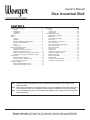
Owner’s Manual
Diva Acoustical Shell
®
CONTENTS
Important User Information . . . . . . . . . . . . . . . . . . . . . . . . . . .2
General . . . . . . . . . . . . . . . . . . . . . . . . . . . . . . . . . . . . .2
Manufacturer . . . . . . . . . . . . . . . . . . . . . . . . . . . . . . . . .2
Intended Use . . . . . . . . . . . . . . . . . . . . . . . . . . . . . . . . .2
Installation . . . . . . . . . . . . . . . . . . . . . . . . . . . . . . . . . . .2
Warranty . . . . . . . . . . . . . . . . . . . . . . . . . . . . . . . . . . . . . . . .3
Safety . . . . . . . . . . . . . . . . . . . . . . . . . . . . . . . . . . . . . . . . . .4
General . . . . . . . . . . . . . . . . . . . . . . . . . . . . . . . . . . . . .4
Installation . . . . . . . . . . . . . . . . . . . . . . . . . . . . . . . . . . .4
Electrical Installation and Maintenance . . . . . . . . . . . . .4
Storage and Transportation . . . . . . . . . . . . . . . . . . . . . .5
Towers . . . . . . . . . . . . . . . . . . . . . . . . . . . . . . . . . . . . . .6
Ceiling Panels . . . . . . . . . . . . . . . . . . . . . . . . . . . . . . . .6
Diva®Acoustical Shell Set Up . . . . . . . . . . . . . . . . . . . . . . . .7
General Information . . . . . . . . . . . . . . . . . . . . . . . . . . . .7
Ceiling Panel Performance Angles . . . . . . . . . . . . . . . .8
Ceiling Panel Storage Position . . . . . . . . . . . . . . . . . . .9
Placing Ceiling Panels into Performance Position . . . .10
Changing the Ceiling Panel Performance Angle . . . . . .11
Tower Set Up . . . . . . . . . . . . . . . . . . . . . . . . . . . . . . . . . . . . .12
Moving Towers from Storage . . . . . . . . . . . . . . . . . . . . .12
Tower Performance Position Setup . . . . . . . . . . . . . . . .16
Tower Wing Panel Doors . . . . . . . . . . . . . . . . . . . . . . . .18
Ceiling Panel Lights . . . . . . . . . . . . . . . . . . . . . . . . . . . . . . . .19
Ceiling Light Electrical Schematic . . . . . . . . . . . . . . . . .19
Ceiling Light Electrical Connection . . . . . . . . . . . . . . . .19
Note:
Note:
Note:
Maintenance . . . . . . . . . . . . . . . . . . . . . . . . . . . . . . . . . . . . .20
Towers . . . . . . . . . . . . . . . . . . . . . . . . . . . . . . . . . . . . . .20
Ceiling Panels . . . . . . . . . . . . . . . . . . . . . . . . . . . . . . . .20
Ceiling Lights . . . . . . . . . . . . . . . . . . . . . . . . . . . . . . . . .20
Tower Replacement Parts . . . . . . . . . . . . . . . . . . . . . . . . . . .21
Diagonal Brace Assembly . . . . . . . . . . . . . . . . . . . . . . .21
Base Frame . . . . . . . . . . . . . . . . . . . . . . . . . . . . . . . . . .22
Vertical Frame Assembly . . . . . . . . . . . . . . . . . . . . . . . .23
Frame Cap . . . . . . . . . . . . . . . . . . . . . . . . . . . . . . . . . .24
Tower Wing-Door-Center Panel . . . . . . . . . . . . . . . . . .25
Lower Filler Panel . . . . . . . . . . . . . . . . . . . . . . . . . . . . .26
Lower Filler Panel Mount Assembly . . . . . . . . . . . . . . .27
Slide Lock Assembly . . . . . . . . . . . . . . . . . . . . . . . . . . .28
Wing Stay Assembly . . . . . . . . . . . . . . . . . . . . . . . . . . .29
Tower Trim Kit . . . . . . . . . . . . . . . . . . . . . . . . . . . . . . . .30
Ceiling Panel . . . . . . . . . . . . . . . . . . . . . . . . . . . . . . . . .31
Ceiling Panel Replacement Parts . . . . . . . . . . . . . . . . .31
Ceiling Panel Stay Assembly . . . . . . . . . . . . . . . . . . . . .32
Bowstring Assembly . . . . . . . . . . . . . . . . . . . . . . . . . . .33
Hanger Arm Assembly . . . . . . . . . . . . . . . . . . . . . . . . . .34
Truss Assembly . . . . . . . . . . . . . . . . . . . . . . . . . . . . . . .35
Ceiling Panel Catch Assembly . . . . . . . . . . . . . . . . . . .36
Ceiling Panel Light Assembly . . . . . . . . . . . . . . . . . . . .37
Please read and understand this Owner’s Manual before working with or using the Diva®
Acoustical Shell.
Refer to the illustrations on the following pages. If you need additional information about your
Diva® Acoustical Shell, write, telephone or email Wenger Corporation at the number below.
It is recommended that two or more people work together when working with Diva® Acoustical
Shell components..
©Wenger Corporation 2008
Printed in USA 01/08
Part #185B750-02
Wenger Corporation, 555 Park Drive, P.O. Box 448, Owatonna, Minnesota 55060-0448
Questions? Call.....USA: (800) 733-0393 • International (call collect): (507) 455-4100 • www.wengercorp.com
IMPORTANT USER INFORMATION
GENERAL
Copyright © 2006 by Wenger Corporation
All rights reserved. No part of the contents of this manual may be reproduced, copied, or transmitted in
any form or by any means including graphic, electronic, or mechanical methods or photocopying,
recording, or information storage and retrieval systems without the written permission of the publisher,
unless it is for the purchaser's personal use.
Printed and bound in the United States of America.
The information in this manual is subject to change without notice and does not represent a commitment
on the part of Wenger Corporation. Wenger Corporation does not assume any responsibility for any
errors that may appear in this manual.
In no event will Wenger Corporation be liable for technical or editorial omissions made herein, nor for
direct, indirect, special, incidental, or consequential damages resulting from the use or defect of this
manual.
The information in this document is not intended to cover all possible conditions and situations that
might occur. The end user must exercise caution and common sense when assembling or installing
Wenger Corporation products. If any questions or problems arise, call Wenger Corporation at 800-7330393.
MANUFACTURER
The Diva® Acoustical Shell is manufactured by:
Wenger Corporation
555 Park Drive
Owatonna, MN 55060
1-507-455-4100 • 1-800-733-0393
www.wengercorp.com
INTENDED USE
The Wenger Diva® Acoustical Shell is intended for indoor use. The Diva® Acoustical Shell is not intended
to be used outside or in wet conditions.
•
•
Never expose the Diva® Acoustical Shell components to wet, humid, or wet outdoor weather
conditions.
The system is not intended to be permanently installed and used in outdoor environments.
INSTALLATION
•
•
•
The Wenger Diva® Acoustical Shell installation and use must comply with local regulations and
codes.
All personnel (including all temporary workers) installing or maintaining the Wenger Diva® Acoustical
Shell must read and understand this entire manual and other related installation instructions.
Always refer to the information on page 4 and 5, Electrical Installation and Maintenance, and page
19, Ceiling Panel Light Electrical Connection, when connecting the Wenger Diva® Acoustical Shell
components to a power source.
2
WARRANTY
The Diva® Acoustical Shell is guaranteed free of defects in materials and workmanship for five full years.
Our guarantee assures you of either a full refund or repair or replacement of the defective materials or
workmanship without charge, at the discretion of our Customer Service Department. Just call a
Customer Service Representative at 1-800-887-7145 and state the reason you are dissatisfied. If a
product return is necessary, your representative will issue a return authorization. This is your sole
remedy for breach of this warranty.
Should you have a question or problem with any Wenger product, don’t hesitate to call, even if the
product is past warranty. It’s important to us that all our customers be satisfied.
This is the sole warranty made by Wenger. Wenger disclaims all other warranties, including the
warranties of merchantability and fitness for a particular purpose, as well as all liability for incidental,
consequential, special, and indirect damage. Wenger liability for direct damages shall be limited to the
amount you paid for the product involved. Wenger reserves the right to make product changes without
obligation to incorporate such changes into products previously sold.
Some states do not allow the exclusion or limitation of damages or warranties, so the above may not
apply to you. This warranty gives you specific legal rights. You may also have other rights which vary
from state to state.
3
SAFETY
GENERAL
Throughout this manual you will find cautions and warnings which are defined as follows.
•
•
WARNING means that failure to follow the instruction may result in serious injury or death.
CAUTION means that failure to follow the instruction may result in serious injury or damage to
property.
Note: Read all of these safety instructions before installing or using Diva® Acoustical Shell
components.
Note:
Failure to comply with warnings and cautions in this document can result in damage to property,
serious injury, death.
INSTALLATION
Warning!
Always wear a hard hat (compliant with ANSI Z89-1997) when installing the Diva®
Acoustical Shell Assemblies. Failure to observe this warning can result in damage to
property, serious injury, or death.
Warning!
Always wear safety glasses and safety shoes and use heavy work gloves when
working on the Diva® Acoustical Shell. Failure to observe this warning can result in
serious injury.
Warning!
Always make sure that personnel, including all temporary personnel, working on the
Diva® Acoustical Shell read and understand this manual. Failure to observe this
warning can result in damage to property, serious injury, or death.
Warning!
Assembly requires two or more persons working together. Some components are
heavy and are difficult to handle alone. Failure to observe this warning can result in
damage to property, serious injury, or death.
Warning!
Care must be exercised because a dangerous pinch point develops when lowering a
Tower Assembly to the floor after lifting it into a vertical position and when placing
Panels onto the floor. Failure to observe this warning can result in serious injury.
Warning!
Never walk or stand on Panels, suspended Ceiling Panels, or Tower Assemblies.
Failure to observe this warning can result in damage to property, serious injury, or
death.
Warning!
When assembling Diva® Acoustical Shell components always observe the warnings
and other information contained in this manual — especially the information on
pages 4, 5, and 6. Failure to observe this warning can result in damage to property,
serious injury, or death.
ELECTRICAL INSTALLATION AND MAINTENANCE
Warning!
Branch circuits that supply power for Ceiling Panel Lights and other accessories
must always be designed by an electrical engineer and comply with electrical codes
and user requirements. Failure to follow this precaution can result in damage to
property, fire, serious injury, or death!
Warning!
Always disconnect power to the Ceiling Panel Lights before cleaning. Failure to
observe this precaution can result in electrical shock or death.
Warning!
Always disconnect power before changing Ceiling Panel Light bulbs. Failure to
observe this precaution can result in electrical shock or death.
4
SAFETY
CONTINUED
ELECTRICAL INSTALLATION AND MAINTENANCE
CONTINUED
Warning!
Do not alter the Ceiling Panel Light electrical circuits without the expressed
permission of Wenger Corporation. Failure to follow this precaution can result in
damage to property, fire, serious injury or death!
Warning!
Replace any broken Ceiling Panel light bulbs immediately. Failure to observe this
precaution can result in electrical shock.
Warning!
Replace any malfunctioning Ceiling Panel electrical components only with
components with the same specification. Failure to observe this precaution can result
in electrical shock, fire, damage to property, serious injury, or death.
Warning:
A licensed electrician must perform the Ceiling Panel electrical installation. Failure to
observe this precaution can result in serious injury, death, or damage to property.
Warning:
All Ceiling Panel Light electrical sources must be permanently wired and comply with
local electrical codes. Failure to observe this precaution can result in serious injury,
death, or damage to property.
STORAGE AND TRANSPORTATION
Warning!
Never use the Air Transporter for any other purpose other than to move and position
Diva® Towers. Failure to observe this precaution can result in serious injury, death, or
damage to property.
Warning!
Never attempt to manually lift or move a Diva Tower without using an Air Transporter.
Failure to observe this precaution can result in serious injury, death, or damage to
property.
Warning!
Never move a Diva® Tower with or without an Air Transporter on an inclined surface
or ramp. Failure to observe this precaution can result in serious injury, death, or
damage to property.
Warning!
Two or more people must work together when moving a Diva® Tower. One person
must always watch for obstructions on the stage and above the stage while a second
person pushes the Air Transporter. Failure to observe this precaution can result in
serious injury, death, or damage to property.
Warning!
Always clear all people and objects from the stage when moving Diva® Towers to or
from storage or when flying Ceiling Panel to or from storage. Failure to observe this
precaution can result in serious injury, death, or damage to property.
Warning!
Always rotate and lock the Tower Wing Panels to the storage position before moving
Tower to or from the performance position. Failure to observe this precaution can
result in serious injury, death, or damage to property.
Warning!
Never move a Diva® Tower faster than one-foot-per-second when transporting to or
from the storage position. Failure to observe this precaution can result in serious
injury, death, or damage to property.
Warning!
Never ride on an Air Transporter. Failure to observe this precaution can result in
serious injury, death, or damage to property.
Warning!
When using the Air Transporter to move a Tower, make sure that all electrical
connections will not separate and interrupt power to the Air Transporter. Failure to
observe this precaution can result in serious injury, death, or damage to property.
5
SAFETY
CONTINUED
TOWERS
Warning!
Only trained and authorized persons should position and adjust Diva® Towers. Failure
to observe this precaution can result in serious injury, death, or damage to property.
Warning!
Never remove a counterweight from a Tower Base. Failure to observe this precaution
can result in serious injury, death, or damage to property.
Warning!
Never climb on a Diva® Tower for any reason. Failure to observe this precaution can
result in serious injury, death, or damage to property.
Warning!
Never mount or hang other equipment, such as lighting, microphones, speakers, etc.,
without consulting Wenger Corporation Customer Service. Failure to observe this
precaution can result in serious injury, death, or damage to property.
CEILING PANELS
Warning!
Only qualified personnel familiar with rigging systems should set up the rigging, add
weights to the Arbor, or fly the Ceiling Panels. Failure to observe this warning can
result in death, serious injury, or damage to property.
Warning!
Always wear safety glasses, gloves, and safety shoes when installing the Diva
Acoustical Shell Ceiling components. Failure to observe this warning can result in
serious injury.
Warning!
Always wear a hard hat (compliant with ANSI Z89-1997) when installing the Diva
Acoustical Shell Ceiling components. Failure to observe this warning can result in
death or serious injury.
Warning!
All personnel working on the rigging above the floor surface must wear a safety
harness. Failure to observe this warning can result in death, serious injury, or
damage to property.
Warning!
Make sure that all rigging and rigging hardware is capable of lifting the Ceiling Panel
component calculated weight plus a reasonable margin of safety. Always comply with
local codes and regulations. Failure to observe this warning can result in damage to
property and serious injury.
Warning!
Make sure that all fasteners are tight before adding any weight to the Arbor. Failure to
observe this warning can result in serious injury or damage to property.
Warning!
Never climb onto or hang from Ceiling Panels in any position. Failure to comply with
this warning can result in death or serious injury.
Warning!
Never mount or hang other equipment such as lights, cameras, microphones, etc.
from a Ceiling Panel or Ceiling Panel rigging without consulting with Wenger
Corporation Customer Service. Failure to observe this warning can result in death,
serious injury, or damage to property.
Warning!
Always clear the stage area of people when moving Ceiling Panel to or from storage.
Failure to observe this warning can result in death, serious injury, or damage to
property.
Warning!
Always fly the Ceiling Panels slowly and have a spotter watch for obstructions or
rigging interference. Failure to observe this warning can result in death, serious
injury, or damage to property.
6
DIVA® ACOUSTICAL SHELL SET UP
GENERAL INFORMATION
Warning!
Always make sure that personnel, including all temporary personnel, working on the
Diva® Acoustical Shell read and understand this manual, especially the safety
information on pages 4, 5, and 6. Failure to observe this warning can result in
damage to property, serious injury, or death.
Warning!
Always wear a hard hat (compliant with ANSI Z89-1997) when installing the Diva®
Acoustical Shell Ceiling Assemblies. Failure to observe this warning can result in
damage to property, serious injury, or death.
Warning!
Always wear safety glasses and safety shoes and use heavy work gloves when
working on the Diva® Acoustical Shell. Failure to observe this warning can result in
serious injury.
Warning!
Assembly requires two or more persons working together. Some components are
heavy and are difficult to handle alone. Failure to observe this warning can result in
damage to property, serious injury, or death.
The Diva® Acoustical Shell can be used for a variety of performance groups such as orchestra
performance, single performance recitals, etc. Tower and Ceiling Panel arrangements can be easily
changed.
The number of Towers and Ceiling Panels used, how they overlap, and the performance angles can be
adjusted for different effects. Some Towers have one or two doors for easy stage access.
Refer to the Installation Drawings and Installation Instructions for the initial set up.
Diva® Tower in Storage
Diva® Tower
Diva® Tower Door
Ceiling Panel Row in
the Storage Position
Ceiling Panel Row in
Performance Position
Performance Area
Proscenium Opening
Auditorium Area
Typical Diva Acoustical Shell Plan View
Diva® Tower
Proscenium Opening
Auditorium Area
Typical Diva Acoustical Shell Elevation View
7
DIVA® ACOUSTICAL SHELL SET UP
GENERAL INFORMATION
CONTINUED
CONTINUED
•
Towers are stored in a nested position off-stage with Wing Panels folded.
•
Ceiling Panel Rows are stored rotated into the vertical position and lifted to the ceiling.
The sequence for setting up the Diva® Acoustical Shell is as follows.
1. Lower the Ceiling Panels first.
a. Place the Ceiling Panels in a position where the Panels can be rotated from the Storage
Position to the Performance Position, then, lift the Ceiling Panel Rows high enough to move
Towers across the stage.
Note: Time can be saved if Tower positions are marked on the stage floor.
b. Move the Towers with an Air Transporter to the performance position and open the Wing Panels
to the Performance position.
c. If the Ceiling Panel Rows have tapered ends, lower each row to a position slightly below the top
of the adjacent Tower on the stage side.
d. If the Tower has a tapered top and the edge of the Ceiling Panel Row extends outside of the
Tower, lower the Ceiling Panel Row to a position four-inches to six-inches above the Tower.
Gaps between the Ceiling Panels and Tower should not be visible from the auditorium area.
CEILING PANEL PERFORMANCE ANGLES
Ceiling Panel Performance angles can be adjusted to achieve different acoustic effects. Refer to the
illustration below.
Acoustic Source
Performance Angles that are
horizontal will return more
acoustic energy to the
performers on the stage.
Acoustic Source
Acoustic Source
Performance Angles that are steeper will return
more acoustic energy toward the auditorium
area.
8
DIVA® ACOUSTICAL SHELL SET UP
CONTINUED
CEILING PANEL STORAGE POSITION
Ceiling Panels are always stored in a vertical position or are placed into the Performance Position. Refer
to the illustrations below.
•
Performance Position — the Ceiling Panel Row is rotated until the Ceiling Stay Receiver engages
the Ceiling Stay Lever (Performance Angle) and is lifted to a position above the stage to reflect
acoustic energy into the auditorium area. Refer to the illustrations on page 8.
•
Storage Position — the Ceiling Panel Row is rotated vertically until the Ceiling Panel Edge
Extrusion is engaged with the Ceiling Panel Catch. Refer to the illustrations below.
Ceiling Panel
Edge Extrusion
Ceiling Panel Row in the
Storage Position
Hanger Arm
Ceiling Panel Catch Plate
engaged with the Ceiling
Panel Edge Extrusion
Ceiling Panel Catch
Plate Assembly
Ceiling Panel Row
Ceiling Catch Strap
Ceiling Panel Catch
Plate Assembly
Ceiling Stay Rod
Ceiling Catch Strap
Ceiling Panel Row
Storage Position
Ceiling Stay Rod
Pulling the Ceiling Catch Strap
downward disengages the Ceiling
Panel Catch Plate Assembly from the
Ceiling Panel Edge Extrusion.
Ceiling Stay Receiver
Ceiling Stay Lever
In the Storage Position, the Ceiling Stay Receiver
is disengaged from the Ceiling Stay Lever.
9
DIVA® ACOUSTICAL SHELL SET UP
CONTINUED
PLACING CEILING PANELS INTO PERFORMANCE POSITION
Warning!
Always make sure that personnel, including all temporary personnel, working on the
Diva® Acoustical Shell read and understand this manual, especially the information on
pages 4, 5, and 6. Failure to observe this warning can result in damage to property,
serious injury, or death.
Warning!
Always wear a hard hat (compliant with ANSI Z89-1997), safety glasses and safety
shoes and use heavy work gloves when working on the Diva® Acoustical Shell.
Failure to observe this warning can result in serious injury.
Warning!
Always clear all people and objects from the stage when moving Diva® Towers to or
from storage or when flying Ceiling Panel to or from storage. Failure to observe this
precaution can result in serious injury, death, or damage to property.
To move a Ceiling Panel Row into the Performance Position, do as follows. Work from the Downstage
side to the Upstage side. Refer to the illustrations below.
1. Clear the stage of all people and objects that might
interfere with lowering Ceiling Panels.
Caution!
Never allow a Ceiling Panel Row Upstage Edge
to touch or strike the stage floor. Failure to
observe this precaution can result in damage.
2. Lower a Ceiling Panel Row until the Upstage Edge nearly
touches, but does not touch, the stage floor (not less
than 6-inches of clearance).
3. Mark this position (Low Trim Position) on the hand line at
the lock rail.
The Ceiling Panel Row is shown in the Storage
Position and lowered to Low Trim, not less
than one-half-foot from the Stage Floor.
Ceiling Panel Row Upstage Edge
4. Move the Ceiling Panels into the Performance Angle.
a. Pull the Ceiling Catch downward and release the Panel from
the Ceiling Panel Catch Plate Assembly.
b. Rotate the Downstage Edge of the Panel Row downward
until the Ceiling Stay Receiver engages the Ceiling Stay
Lever.
5. Clear the stage and lift the Ceiling Panel Row to the
Performance Position. Make sure that the Ceiling Panel Row
does not swing while lifting it.
6. Repeat steps 1 through 5 for the other Ceiling Panel Rows.
Ceiling Stay Receiver
Ceiling Stay Rod
Ceiling Panel Catch
Plate Assembly
Ceiling Catch Strap
Release th Catch Plate
Assembly.
Ceiling Panel Row
Downstage Edge
Rotate the Panel Row to
the Performance Position.
Ceiling Stay Lever
10
DIVA® ACOUSTICAL SHELL SET UP
CONTINUED
CHANGING
THE CEILING PANEL PERFORMANCE ANGLE
To change a Ceiling Panel Row Performance Angle, do as follows. Refer to the illustrations below.
1. Clear the stage of all people and objects that might interfere with lowering Ceiling Panels.
Caution! Never allow a Ceiling Panel Row Upstage Edge to touch or strike the stage floor.
Failure to observe this precaution can result in damage.
2. Lower a Ceiling Panel Row to the Low Trim Position (make sure that the Upstage Edge does not
touch the stage floor has not less than 6” of clearance to the stage floor).
3. With two or more people working together, rotate the Ceiling Panel into the current Performance
Position.
a. Pull the Ceiling Catch downward and release the Panel from the Ceiling Panel Catch Plate
Assembly.
b. Rotate the Downstage Edge of the Panel Row downward until the Ceiling Stay Receiver
engages the Ceiling Stay Lever.
4. Use a pair of 7/16” combination wrenches to loosen all of the Hex Head Screws (four) and Locknuts
on the Ceiling Stay Receiver while two people hold the Ceiling Panel Upstage Edge.
5. With two people working together grasping the Upstage Edge, rotate the Ceiling Panel Row slightly
above the new Performance Angle (perhaps five to ten-degrees) making sure that the Ceiling Stay
Receiver remains engaged with the Ceiling Stay Lever. Ceiling Panel Rows are heavier on the
Upstage Side.
Ceiling Stay Receiver
Hex Head Screws
and Locknuts
Performance Angle
Ceiling Stay Lever
Ceiling Stay Rod
6. Use the pair of 7/16” combination wrenches and tighten all of the Hex Head Screws (four) and
Locknuts on the Ceiling Stay Receiver while two people hold the Ceiling Panel Upstage Edge.
7. Check the Performance Angle and make any necessary adjustments.
Note: If the Performance Angle is changed often, mark the positions on the Ceiling Stay Rod.
8. Lift the Ceiling Panel Row to the Performance Position. Make sure that the Ceiling Panel Row does
not swing while lifting it.
11
TOWER SET UP
MOVING TOWERS FROM STORAGE
Warning!
Always use the Air Transporter when moving Diva® Towers. Never attempt to move
Diva® Towers without using the Air Transporter. Failure to observe this warning can
result in damage to property, serious injury, or death.
Warning!
Always wear a hard hat (compliant with ANSI Z89-1997) when moving the Diva®
Towers. Failure to observe this warning can result in damage to property, serious
injury, or death.
Warning!
Always wear safety glasses and safety shoes and use heavy work gloves when
moving the Diva® Towers. Failure to observe this warning can result in serious injury.
Warning!
Always use an Air Transporter to transport a Diva® Tower. Failure to observe this
precaution can result in serious injury, death, or damage to property.
Warning!
Never move a Diva® Tower on an inclined surface or ramp with or without using the
Air Transporter. Failure to observe this precaution can result in serious injury, death,
or damage to property.
Warning!
Never ride on an Air Transporter. Failure to observe this precaution can result in
serious injury, death, or damage to property.
Warning!
Connect the Air Transporter Power Cord to a fused, grounded, 120 VAC, 15 ampere,
14 gauge power cord. Failure to observe this precaution can result in serious injury,
death, fire, or damage to property.
1. Connect the Air Transporter Power Cord to a 14 gauge extension cord that connects to a fused,
grounded, 120 VAC, 15 ampere power source. Make sure that the extension cord is long enough to
reach wherever the Air Transporter will be moved.
Release Lever
Air Transporter
Foot Switch
Power Cord Plug
Power Cord
Connect the Power Cord Plug to a 14
gauge extension cord that connects to a
fused, grounded, 120 VAC, 15 ampere
power source
12
TOWER SET UP
CONTINUED
MOVING TOWERS FROM STORAGE
Warning!
CONTINUED
Make sure that all electrical connections will not separate and interrupt power to the
Air Transporter when moving a Tower. Failure to observe this precaution can result in
serious injury, death, or damage to property.
2. To move the Air Transporter when not supporting a Tower, tilt the front of the Air Transporter upward
on the rear casters about 10 to 15-degrees. The front caster will drop downward into place.
To move the Air Transporter when not
supporting a Tower, tilt the Front End
upward about 10-degrees.
3. Place the Air Mover under the Tower Assembly
with the Lifting Hooks under the Lifting
Brackets on Tower Assembly. Refer to the
illustrations below and right.
Lifting Bracket
Tower
Air Mover Lifting Hook
Lifting Bracket
Air Transporter
Air Mover Lifting Hook
13
TOWER SET UP
CONTINUED
MOVING TOWERS
Warning!
Warning!
FROM STORAGE CONTINUED
Two or more people must work together when moving a Diva® Tower. One person
must always watch for obstructions on the stage and above the stage while a second
person pushes the Air Transporter. Failure to observe this precaution can result in
serious injury, death, or damage to property.
Always clear all people and objects from the stage when moving Diva® Towers to or
from storage . Failure to observe this precaution can result in serious injury, death, or
damage to property.
Air Transporter
Release Lever
4. Lift the Release Lever to extend the air pads to the floor.
Air Transporter Handle
5. Turn on the Air Transporter air blower by placing
the Foot Switch into the on position (press the left
side of the switch).
Note: Make sure that both Lift Hooks engage the
Lifting Brackets.
Foot Switch
Warning!
Always rotate and lock the Tower Wing Panels
to the storage position before moving Tower
to or from the performance position. Failure to
observe this precaution can result in serious
injury, death, or damage to property.
6. Using the Air Transporter, slowly move the Tower about 5’
from the other Towers.
7. Stop moving the Tower so that a second person can make
sure that the Wing Panels are locked in the storage
position and that the Wing Doors are locked to the Wing
Panels.
14
TOWER SET UP
CONTINUED
MOVING TOWERS FROM STORAGE
Warning!
CONTINUED
®
Never move a Diva Tower faster than one-foot-per-second when transporting to or
from the storage position. Moving a Tower carelessly or too fast can cause a serious
accident such as tipping the Tower over, running into objects, etc. Failure to observe
this precaution can result in serious injury, death, or damage to property.
8. With one person pushing the Air Transporter and a second person guiding, slowly move (no faster
than one-foot-per-second) the Tower to the performance position. Be careful to not push the Tower
into any obstructions on the stage floor or above the stage floor (such as Ceiling Panels, etc.).
Note:
It is best to create permanent marks for the performance positions for all Towers before moving
the Towers from Storage.
9. When the Tower is in the performance position, turn off
the Air Transporter Air Blower by placing the Foot Switch
into the off position (press the right side of the switch).
Note:
As the air escapes from the Air Transporter air pads,
the Tower will tilt slightly forward.
When the Tower is in the Performance Position,
turn off the Air Blower by placing the Foot
Switch into the off Position.
Foot Switch
10. Remove the Air Transporter from the Tower as
follows.
a. When the air pads are deflated, pull the Air
Transporter away from the Tower so that the Lift
Hooks are clear of the Tower Lift Brackets.
b. Place a foot against the rear of the Air
Transporter and tilt the front upward until the
front caster locks into place (down position).
c. Move the Air Transporter to the next Tower to
be moved.
Air Transporter
Air Transporter
Pull the Air Transporter clear of the Tower and tip the Air
Transporter front end upward to deploy the front caster
(lock into the down position).
11. Move other Towers to performance positions by repeating steps 3 to 10.
15
TOWER SET UP
CONTINUED
TOWER PERFORMANCE POSITION SETUP
Prepare the Tower for performance as follows.
1. Position the Tower Wing Panels.
a. Turn the Wing Stay Lock about one-half
turn counterclockwise to release the Wing
Panel.
b. Rotate the Wing Panel to the Performance
Position.
c. Lock the Wing Panel by turning the Wing
Stay Lock clockwise until snug.
d. Position the opposite Wing Panel by
repeating steps 1a through 1c.
e. Place the other Tower Wing Panels into
the Performance Position.
f. If necessary, adjust the Tower positions
with the Air Transporter.
Wing Panel
Wing Stay Lock
Tower with Wing Panels in the
Performance Position
2. Level the Towers as follows. Towers should be level and
adjacent Wing Panels should be even.
a. Use a 48” box level or similar tool and check the level
of each Tower.
b. Adjust the Leveling Pads with a drift pin or similar tool
as necessary. Turning the Leveling Pad clockwise
increases the height of the Tower.
Use a box level or similar tool and
make sure that the each Tower is
level and that the adjacent Wing
Panels are even.
Turn clockwise to increase
the height of the Tower.
Drift Pin
Leveling Pad
16
TOWER SET UP
CONTINUED
TOWER PERFORMANCE POSITION SETUP CONTINUED
3. Install the Lower Center Filler Panel to the Tower as follows.
a. Lift the Lower Center Filler Panel away
from the Storage Bracket Mount Clip.
Lower Center Panel
Lower Center Filler Panel
Storage Bracket
Mount Clip
b. Align the Filler Panel just below the Lower Center
Panel. It may be necessary to fit the Panel
through the opening from the outside.
c. Holding the Panel Handles, place the Lower
Filler Panel into position below the Lower Center
Panel.
d. Lock the Lower Center Filler Panel to the Lower
Center Panel with one person holding the Filler
Panel in place and a second person engaging
the Hook Rods with the Locking Lever and
closing the Locking Lever. See the illustration
below.
Lower Center Panel
Lower Center Filler Panel
Lower Center Panel
Panel Latch Lever
Lower Center
Filler Panel
Hook Rods
Holding the Lower Center Filler Panel
in place, lock the Panel to the Lower
Center Panel with the Panel Latch.
Panel Latch Lever
Lower Center Filler Panel
17
TOWER SET UP
CONTINUED
TOWER WING PANEL DOORS
Wing Panels with a Door open as follows.
Note: When two Doors are adjacent, always open the the Door without Edge Trim first.
1. Turn the Slide Lock Knob counterclockwise to release the Slide Lock Slide.
2. Pull the Slide Lock Slide downward to clear the Slide Lock Keeper and turn the Slide Lock Knob
clockwise until it is snug.
3. Open the Door.
Wing Panel Door
Wing Panel Door
Slide Lock Keeper
Slide Lock Knob
Slide Lock Slide
Door Panel Slide Lock
18
CEILING PANEL LIGHTS
CEILING LIGHT ELECTRICAL SCHEMATIC
575 watt Light Fixture
8-Gauge Green
8-Gauge White
Wire Nut
8-Gauge Black
Tilt Switch,
25 Ampere
Wire Nut
Ground
8-Gauge Green
8-Gauge Black
8-Gauge White
8-Gauge Black
Twist-lock Plug,
3-wire, 120 VAC
Wire Nut
CEILING LIGHT ELECTRICAL CONNECTION
Warning!
Branch circuits that supply power to the Ceiling Light must always be designed by
an electrical engineer, permanently wired, and comply with electrical codes and
user requirements. Failure to follow this precaution can result in damage to
property, serious injury or death!
Warning!
Always disconnect power to the Ceiling Panel Lights before cleaning. Failure to
observe this precaution can result in electrical shock or death.
Warning!
Always disconnect power to the light switch before changing Ceiling Panel Light
bulbs. Failure to observe this precaution can result in electrical shock or death.
Warning:
A licensed electrician must perform the Ceiling Panel electrical installation. Failure
to observe this precaution can result in serious injury, death, or damage to
property.
Connect the Ceiling Panel Light Power Cord to a grounded, fused, threewire, 120VAC, 25 ampere power source with a twist-lock receptacle. The
power source must comply with local electrical codes.
Ceiling Panel Panel
Power Cord Plug
Grounded, Twist-lock
Receptacle, 120VAC,
25 ampere
19
MAINTENANCE
TOWERS
1. Clean surfaces with a mild, non-abrasive detergent when soiled.
2. Make sure that all fasteners are tight.
3. Replace any damaged part immediately.
4. Lubricate any Leveler parts that do not move freely with a general purpose grease.
5. Immediately replace any missing counterweights with a Wenger Corporation replacement part.
6. Make sure that all hinges move freely. If necessary, replace worn or damaged hinges.
7. Replace any damaged rear frame casters.
CEILING PANELS
1. Clean surfaces with a mild, non-abrasive detergent when soiled.
2. Make sure that all fasteners are tight.
3. Inspect rigging before flying or storing Ceiling Panels.
4. Make sure that all hanger brackets turn freely on truss assemblies. Replace parts as necessary.
5. Check Ceiling Panel Performance Angles and adjust when necessary. Make sure that the Ceiling
Panel Ceiling Stay Levers work and move easily.
CEILING LIGHTS
Warning!
Always disconnect power to the Ceiling Panel Lights before cleaning. Failure to
observe this precaution can result in electrical shock or death.
Warning!
Always disconnect power before changing Ceiling Panel Light bulbs. Failure to
observe this precaution can result in electrical shock or death.
Warning!
Replace any broken Ceiling Panel light bulbs immediately. Failure to observe this
precaution can result in electrical shock.
Warning!
Replace any malfunctioning Ceiling Panel electrical components only with
components with the same specification. Failure to observe this precaution can result
in electrical shock, fire, damage to property, serious injury, or death.
1. Replace burned out lamps with a 120 VAC, 575 watt flood lamp.
2. Make sure that all Ceiling Light Power Cord Plugs are connected to grounded, twist-lock receptacles
in a locked position.
3. Make sure that all power cords are not frayed or under tension when the Ceiling Panels are
deployed or stored.
4. Make sure that each Ceiling Light Tilt Switch works correctly before the Ceiling Panel is moved to
the performance position.
20
TOWER REPLACEMENT PARTS
DIAGONAL BRACE ASSEMBLY
7
8
4
5
4
4
6
8
7
1
2
Item
6
Description
1
Diagonal Rod, 1-8 x 3’
2
3
Horizontal Mounting Bracket
Vertical Mounting Bracket
4
Hex Nut, 1-8
5
Polyethylene Extrusion
6
Hex Head Screw, 3/8-16 x 31/2”
7
Locknut, 3/8-16
8
Washer, Nylon, 1” Inside Diameter
21
3
TOWER REPLACEMENT PARTS
CONTINUED
BASE FRAME
4
3
2
6
7
5
8
9
1
10
Item
Description
1
Base Frame Side Frame
2
3
Base Frame Rear Frame
Base Frame Caster Mount
4
Caster Mount Cap
5
Swiveling Caster, 6” diameter
6
Hex Head Screw, 3/8-16 x 31/2”
7
Hex Head Screw, 3/8-16 x 1”
8
Locknut, 3/8-16
9
Flat Washer, .410” ID x 3/4” outside diameter
10
Counterweight
22
TOWER REPLACEMENT PARTS
CONTINUED
VERTICAL FRAME ASSEMBLY
5
3
9
3
2
1
4
10
3
8
11
7
6
15
3
14
18
13
16
10
17
12
Item
Item
Description
Description
1
Right Hand Vertical Frame**
11
Upper Leveler Bracket
2
Left Hand Vertical Frame**
12
Shoulder Screw, 1/2 x 3/4”
3
Cross Brace
13
Floor Plate
4
Outer Hinge
14
Leveler Bearing
5
Inner Hinge
15
Lower Leveler Bracket
6
Fixed Outer Bracket
16
Frame Transition Assembly
7
Fixed Inner Bracket
17
Hex Head Screw, 3/8-16 x 31/2”
18
Locknut, 3/8-16
8
1
Square Lock Nut, /4-20
1
9
Hex Socket Screw, /4-20 x 1”
10
Self-drill Screw, 1/4-20 x 1”
** Specify length
23
TOWER REPLACEMENT PARTS
CONTINUED
FRAME CAP
5
4
3
Frame Cap
5
2
4
1
3
2
Item
Description
1
Rear Frame End Cap, 20.68”
2
3
Short Side Frame End Cap, 5.43”
Long Side Frame End Cap, 29.50”
4
Lower Vertical End Cap, 15.75”
5
Upper Vertical End Cap (specify length from 28 to 192”)
24
TOWER REPLACEMENT PARTS
CONTINUED
TOWER WING-DOOR-CENTER PANEL
1
2
3
5
4
6
7
Item
Description
1
Tower Panel**
2
3
Inner Corner Clip
Outer Corner Clip
4
Self-drill Screw, 1/4-20 x 1”
5
Polyethylene Extrusion
6
Carriage Bolt, 1/4-20 x 31/2”
7
Hex Nut, 1/4-20
** Specify length
25
TOWER REPLACEMENT PARTS
CONTINUED
LOWER FILLER PANEL
11
12
10
9
8
2
7
13
6
1
5
4
3
14
Item
Item
Description
Description
1
Lower Filler Panel
10
2
3
Polyethylene Extrusion
Door Handle
11
Panel Latch Lever
12
Panel Latch Bracket
4
Inner Corner Clip
13
Hinge Rod
5
Outer Corner Clip
14
Blind Rivet, 3/16” x 3/8”
1
6
Hex Head Self-drill Screw, /4-20 x 1”
7
Panel Latch Lever Bracket
8
Spring Pin, 5/16” x 13/4
9
Left Hook Rod
26
Right Hook Rod
TOWER REPLACEMENT PARTS
CONTINUED
LOWER FILLER PANEL MOUNT ASSEMBLY
4
5
6
3
2
1
2
Item
Description
1
Filler Panel Mounting Bracket
2
3
Ribbed Plug
Filler Panel Mounting Clip
4
Filler Panel Mounting Clip Cushion
5
Cotter Pin, 5/32” x 3/4”
6
Self-drill Hex Head Screw, 1/4-14 x 3/4”
27
TOWER REPLACEMENT PARTS
CONTINUED
SLIDE LOCK ASSEMBLY
4
2
5
1
3
6
7
Item
Description
1
Slide Lock Housing
2
3
Slide Lock Knob
Slide Lock Slide
4
Slide Lock Keeper
5
Door Handle
6
Slide Lock Cushion
7
Phillips Pan Head Screw, 1/4-20 x 5/8”
28
TOWER REPLACEMENT PARTS
CONTINUED
WING STAY ASSEMBLY
6
5
4
8
2
1
9
11
7
6
10
3
6
Description
Item
1
End Bracket
7
Hex Head Capscrew, 3/8-16 x 13/4”
2
3
Wing Stay Tube
Wing Stay Channel
8
Hex Head Capscrew, 3/8-16 x 21/4”
9
Hex Head Capscrew, 5/16-18 x 13/8”
4
Stay Base Bracket
10
Wing Stay Lock
5
Flat Washer, 3/8” x 11/4”
11
Phillips Pan Head Screw, 10-24 x 5/8”
Item
6
3
Locknut, /8-16
29
Description
TOWER REPLACEMENT PARTS
CONTINUED
TOWER TRIM KIT
1
5
2
4
3
6
Item
1
2
3
Description
Panel Trim Strip (specify length — 96 to 237”)
Lower Center Panel Trim Strip, 615/8”
Filler Panel Trim Strip, 331/2”
4
Edge Clip
5
Trim Clip
6
Phillips Pan Head Screw, 10-24 x 5/8”
30
CEILING PANEL REPLACEMENT PARTS
CEILING PANEL
7
8
2
6
1
5
4
3
Item
9
Description
1
Ceiling Panel (specify size)
2
3
Ceiling Panel Channel (specify length)
Outer Corner Clip
4
Inner Corner Clip
5
Self-drill Screw, 1/4-20 x 1”
6
Blind Rivet, 3/16” x 3/8”
7
Carriage Bolt, 1/4-20 x 31/2”
8
Hex Nut, 1/4-20
9
Polyethylene Extrusion
31
CEILING PANEL REPLACEMENT PARTS
CONTINUED
CEILING PANEL STAY ASSEMBLY
11
17
18
16
3
15
2
1
4
6
10
7
14
11
5
8
13
12
9
11
Item
Item
Description
Description
1
Ceiling Panel Stay Tube and Bracket
11
Locknut, 3/8-16”
2
3
Compression Spring, .720” diameter
Locknut, 5/16-18
12
Ceiling Stay Rod
13
Hex Head Capscrew, 1/4-20 x 11/4”
4
Bearing, 3/8” inside diameter
14
Latch Receiver Plate
5
Latch Bar
15
Locknut, 1/4-20
16
Hex Head Capscrew, 5/16-18 x 13/8”
6
3
7
Hex Socket Shoulder Bolt, /8” x /8”
1
5
7
Spring Pin, /4” x 1 /8”
17
Stay Base Bracket
8
End Bracket
18
Flat Washer, 3/8 x 11/4”
3
1
9
Hex Head Capscrew, /8-16 x 2 /4”
10
Hex Head Capscrew, 3/8-16 x 13/4”
32
CEILING PANEL REPLACEMENT PARTS
CONTINUED
BOWSTRING ASSEMBLY
1
9
10
2
8
3
11
2
7
4
5
6
8
Item
Description
Item
Description
Bowstring (specify size and length)
7
Bowstring Jack Jam Nut
2
3
Ceiling Clip
Bowstring Jack
8
Self-drill Screw, 1/4-14 x 3/4”
9
Locknut, 3/8-16
4
Bowstring Jack Tube
10
Self-tapping Screw, 5/16-18 x 1”
5
Hanger Bracket
11
Hex Head Screw, 3/8-16 x 21/4”
6
Hanger Bearing Rod
1
33
CEILING PANEL REPLACEMENT PARTS
CONTINUED
HANGER ARM ASSEMBLY
5
6
4
7
9
8
3
10
2
11
1
Item
Item
Description
Description
Locknut, 3/8-16
1
Bowstring
7
2
3
Turnbuckle
Hex Head Screw, 3/8-16 x 2”, Grade 5
8
Hex Head Screw, 1/2-13 x 13/4”, Grade 5
9
Hanger Strap
4
Hex Head Screw
10
Locknut, 1/2-13
5
Batten Clamp
11
Carriage Bolt, 1/2-13 x 33/4”
6
Locknut
34
CEILING PANEL REPLACEMENT PARTS
CONTINUED
TRUSS ASSEMBLY
6
3
4
5
2
1
Item
Description
1
Ceiling Truss, (specify length: 4, 8, 12, 16, 20’
2
3
Ceiling Truss Cap, (specify length: 4, 8, 12, 16, 20’)
Splice Bracket
4
Splice Bar
5
Button Head Hex Socket Screw, 3/8-16 x 3/4”
6
Washer, 3/8” Inside diameter x 11/4” outside diameter
35
CEILING PANEL REPLACEMENT PARTS
CONTINUED
CEILING PANEL CATCH ASSEMBLY
6
2
4
3
4
5
7
7
1
2
Item
Description
1
Pivot Plate
2
3
Catch Plate
U-Bolt, 1/4-20 x 2” inside
4
Spacer, Tube
5
Ceiling Catch Strap
6
Hex Head Screw, 1/4-20 x 3”
7
Locknut, 1/4-20
36
CEILING PANEL REPLACEMENT PARTS
CONTINUED
CEILING PANEL LIGHT ASSEMBLY
4
9
3
10
11
2
12
1
13
20
19
18
17
16
15
14
5
8
Item
6
10
Item
Description
Description
Flood Light Fixture, 575 watt
11
Cable Strain Relief, Liquid Proof
2
Lamp, 575 watt, 120VAC, 2000 Hour
12
Conduit Locknut, 1/2” NPT
3
Light Mount Assembly
13
Ground Wire, R-98-8, Green
4
Light Power Cord, 3 wire, twist-lock
14
Blind Rivet, 3/16” x 1/4”
5
Light Trim Ring
15
Blind Rivet, 1/8” x 1/8”
6
Electrical Junction Box, 4” x 4” x 11/2”
16
Truss Head Screw, 8-18 x 3/8”
7
Flat Cover, 4” x 4” (not shown)
17
Pan Head Screw, 10-18 x 3/4”
8
Switch, tilt, 25 ampere, cotton lead
18
Self-drill Screw, 1/4-20 x 1”
9
Tilt Switch Mounting Clip
19
Hex Head Screw, 1/2-13 x 1”
10
Wire Nut, wing, yellow
20
Locknut, 1/2-13
1
37