1
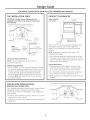
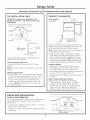
Design Guide with
Installation
Instructions
Double-Drawer
ZIDI240
ZIDS240
monogram.com
Built-In Refrigerator
Safety Information
BEFORE YOU BEGIN:
WARNING:
Read these instructions completelg and carefullg.
• Double-DrowerRefrigerotors
oredesignedtobe
built-in
only.
They connotbe used free-stonding.
IM PORTANT - Sove
these
instructions
for Iocol inspector's use.
IMPORTANT
Use this
opplionce
onlyforitsintendedpurpose.
• Immediotely repoir or reploce electricol service cords
thot become froyed or domoged.
- Observeollgoverning codes
ond ordinonces.
Note to Installer
- Be sure to leove these
instructions with the Consumer.
Unplug the unit before cleoning or moking repoirs.
Repoirs should be mode by o quolified service
technicion.
Note to Consumer
AVERTISSEMENT :
WARNING
• Les r_frig_roteurs (_deux tiroirs sont conqus pour
@treencostr@suniquement. IIs ne peuvent pos @tre
s_por_s.
- Keepthese instructions with
your Owner's Honuol for future reference.
- Thisopplionce
must be
properly
grounded.Seethesection
below.
AVERTISSEMENT Cet opporeil doit @trecorrectement mis 5 Io terre.
Consulter Io section ou-dessous.
If you received o domoged Double-Drower Refrigerotor,
you should immediotely contoct your deoler or builder.
Skill Level -Instollotion requires bosic mechonicol
skills. Proper instollotion is the responsibility of the
instoller. Product foilure due to improper instollotion
is not covered under the GE Applionce Worronty.
• II ne fout utiliser cet opporeil que pour I'usoge pour
lequel il o @t@
construit.
• II fout r@porerou remplocer imm@diotement tout
cordon d'olimentotion @lectrique effiloch@ou
endommog&
D@broncherle bor ou le r_frig_roteur o vin ovont
le nettoyoge ou toute intervention.
Les r@porotionsdoivent @trefoites por un technicien
quolifi&
For Monogram local service in your area, call
1.800.444.1845
For Monogram service in Canada, call
1.800.561.3344
For Monogram Parts and Accessories, call
1.800.626.2002.
www, monogram,com
GROUNDING THE DOUBLE-DRAWER
REFRIGERATOR
IMPORTANT
-
Pleose reod corefully.
FOR PERSONAL SAFETY,THIS APPLIANCE MUST
BE PROPERLY GROUNDED.
The power cord of this opplionce is equipped with
o three-prong (grounding) plug which motes with o
stondord three-prong (grounding) wall receptocle to
minimize the possibility of electric shock hozord from
this opplionce.
Hove the woll outlet ond circuit checked by o quolified
electricion to moke sure the outlet is properly grounded.
Where o stondord 2-prong woll outlet is encountered,
it is your personol responsibility ond obligotion to hove it
reploced with o properly grounded 3-prong woll outlet.
DO NOT, UNDER ANY
CIRCUMSTANCES, CUT
OR REMOVE THE THIRD
(GROUND) PRONG
FROM THE POWER CORD.
DO NOT USE AN ADAPTER PLUG
TO CONNECT THE REFRIGERATOR
TO A 2-PRONG OUTLET.
DO NOT USE AN EXTENSION
CORD WITH THIS APPLIANCE.
Important Information
CONTENTS
Design Guide (for ZIDI240}
Important Information
Step 3, Level ..................................................
7
The Installation Space ..............................
5
Tools, Hardware ........................................
3
Product CleQrances....................................
5
Step 4, Connect Power ............................
8
Parts Required ..............................................
S
Step 5, Slide Product into Cutout ........8
Side-bg-Side Installotions ......................
5
Coring for Your Stainless Steel ............
S
Step 6, Set Temperature Controls ......8
Installation Instructions
Design Guide (for ZIDS240}
Step 1, Remove PQckQging....................
6
The Installation Space ..............................
4
Product CleQrances....................................
4
Step 2, Install Custom 3/4"
Drawer Panels and Handles
Side-bg-Side Installotions ......................
4
(ZIDI240 model onlg) ............................
6, 7
CARING FOR YOUR STAINLESS STEEL
ZIDI240 MODEL ONLY
PARTS REQUIRED
PARTS SUPPLIED
• Custom hQndles
• Dower side trims
• Overlag pQnels
• OptionQI block or
stainless steel toekick
• SpQcer pQnels
• Backer pQnels
• Screws
TOOLS REQUIRED
• Adjustable wrench
• CQrpenter's glue (ZIDI240 model onlg)
• Screwdriver (ZIDI240 model onlg)
• Before installQtion or first use, we stronglg advise gou
polish the stainless steel exterior and handles with a
commerciallg available stainless steel cleQner such
as Stainless Steel Magid'. To preserve and protect
the fine finish, we also stronglg advise thQt gou
applg stainless steel cleQner monthlg.
Design Guide
FOR MODEL ZIDS240
THE INSTALLATION
WITH
STAINLESS STEEL DRAWERS AND
SPACE
IMPORTANT: Double-Drawer
Refrigerators
designed
to be built-in only. They cannot
free-standing.
HANDLES
PRODUCT CLEARANCES
are
be used
When installed
in a corner:
/
Countertop
Ik
Double-Drawer
--_/'22"min.
/
34-1/4"
to 34-3/4"
Clearance
forDoor
Opening
2-1/2"min.
Allow 2-1/2'* min. clearance between Double-Drawer
and adjacent cabinet, wall or other appliances.
Allow 22" min. clearance from the front for drawer
opening.
NOTE:Clearances are based on the noted 2-1/8"
handle standoff depth.
[
NOTE:
Handle and
handle standoff
depth is 2-2/8"
34-1/4"
Including
25-7/8"
Handles
'to 34-3/4"
\\\
\
• Test the drawer openings. Carefullg open and close
the drawers. The drawers should not rub or catch on
adjacent cabinetry. Notify the installer if the drawers
make contact with cabinetry.
The cutout depth should be 24"
NOTE:The unit is designed to be flush with the
surrounding cabinets.
Choose the locution:
• These products mug be closed in on the top and
three sides as long as the front is unobstructed for
air circulation and proper access to the drawers.
Additional Specifications
• A 120 volt 60Hz., 15 or 20 amp power supply is required.
An individual properly grounded branch circuit or circuit
breaker is recommended. Install a properly grounded
]-prong electrical receptacle recessed into the back
wall as shown. Electrical must be located on rear wall
as shown. NOTE:GFCI(ground fault circuit interrupter)
is not recommended.
SIDE-BY-SIDE
• Do not install these products where the temperature
will go below 55°F (!3°C) or above 90°F (32°C).
• These products are not designed to be stacked one over
the other.
INSTALLATIONS-
Stainless Steel Models Only
For a complete refreshment center, install a Double-Drawer
Refrigerator beside a Beverage Center, Wine Chiller/
Wine Reserve, Fresh-Food Refrigerator or Bar Refrigerator
with Icemaker.
34-1
• A side-by-side installation requires at least a 47-1/2" wide
opening. No trim kits required.
• Products must operate from separate, properly grounded
receptacles.
4
Design Guide
FOR MODEL ZIDI240
THE INSTALLATION
WITH
CUSTOM
SPACE
IMPORTANT: Double-Drawer
Refrigerators
designed to be built-in onlg. Theg cannot
free-standing.
DRAWER
PANELS AND HANDLES
PRODUCT CLEARANCES
ore
be used
When installed
in a corner:
/
CounteRop
11,,
Double-Drawer
Z-,,"23-1/8"min.
/
Clearance
forDoor
Opening
2-1/2"min.
23-3/4"Min
] 3:1j4
NOTE: Handles
not supplied.*
to 34-3/4"
24-7/8''_ __ 23-3/4......
*Custom handle clearances may vary, depending on the
standoff of the custom handles.
The cutout depth should be 24"
The cutout dimensions shown allow for full drawer
extension.
NOTE:The drawers should be flush with the surrounding
cabinets.
Additional Specifications
• A 120 volt 60Hz., !5 or 20 amp power supply is required.
An individual properly grounded branch circuit or circuit
breaker is recommended. Install a properly grounded
3-prong electrical receptacle recessed into the back
wall as shown. Electricalmust be located on rear wall
as shown. NOTE:GFCI(ground fault circuit interrupter)
is not recommended.
SIDE-BY-SIDE
Allow 2-1/2" min. clearance between Double-Drawer and
adjacent cabinet, wall or other appliances. Allow 23-:]z8"
min. clearance from the front for drawer opening.
NOTE:Custom handle clearances may vary depending on
the standoff of the custom handles.
• Test the drawer openings. Carefully open and close
the drawers. The drawers should not rub or catch on
adjacent cabinetry. Notify the installer if the drawers
make contact with cabinetry. NOTE:When installing
custom panels and handles, use above clearances as
a general guide but adjust according to the installation.
Choose the locution:
• These products may be closed in on the top and
three sides as long as the front is unobstructed for
air circulation and proper access to the drawers.
• Do not install these products where the temperature will
go below 55°F(13°C)or above 90°F(32°C).
• These products are not designed to be stacked one over
the other.
Black or Stainless Steel Toekick Options
• These products are shipped with two toekicks,
a stainless steel and a black toekick. For shipping
purposes, one of the toekicks will be secured to
the back of the unit and the second will be installed,
in place, on the unit. Keep the unused toekick,
and other unused or removed parts, for future use.
INSTALLATIONS-
Custom Panel Models Only
For a complete refreshment center, install a Double-Drawer
Refrigerator beside a Beverage Center or Wine Chiller/
Wine Reserve.
T I
• A side-by-side installation requires at least a 47-1/2" wide
opening. No trim kits required.
34-1
• Products must operate from separate, properly grounded
receptacles.
r___,Mi
I
__
1 14"10-1 /2"
__
,,
*NOTE:Additionalclearunces
may be required.
Installation
ISTEP11 REMOVE
Instructions
ISTEP 2 1INSTALL CUSTOM 314"
PACKAGING
• Remove corner blocks and foam drawer stops.
• Remove all packing material, tape and protective
plastic coverings.
DRAWER PANELS AND
HANDLES (CONT.)
(ZIDI240 model onlg)
CAUTION: Small objects area
choke hazard
for children. Remove and discard any parts not used.
Instell custom drawer panels end hendles:
• Open drawers.
ATTENTION : ,espetits objets peuvent
• Remove 2 screws holding each trim; lift trims off.
Retain screws.
_trangler les enfants. II fautjeter toutes les pi_ces qui
ne sont pas utilis_es.
ISTEP
el
INSTALL CUSTOM 314"
DRAWER PANELS AND HANDLES
(ZIDI240 model onlg)
3/4" Overlag Panel Dimensions
ModelZIDI240 requiresfield-installed
overlag drawer panels.
• The overlag panels must be secured
to 1/4" thick backer panels that
slide into the trims. A .10" thick
spacer panel must be placed
between the overlag and backer
panels.
Drawer
1/4"
• Custom handles of gour choice,
Backer
_ _-.10
Inch
supplied bg gour cabinet maker,
Panel
Spacer
must be installed on these overlag panels. Countersink
all screws into the backer panels. Screwscannot
protrude from the backer panels.
IMPORTANTNOTE:Maximum total weight for custom
drawer panels are 25 pounds (12-1/2 pounds maximum
each drawer).
1/4"
T
*
12-1/2 Ibs. max.
ScrewsMust
BeCountersunk
IntoPanel
Ha!dlE_e
DrawerPanel
• Slide overlag panels into the trims.
A
12-1/2 Ibs. max.
• Custom handles of gour choice, supplied bg gour
cabinet maker, must be installed onto the overlag
panels before theg are slid into the trims. Countersink
all screws into the backer panels. Screws cannot
protrude from the backer panels.
23-3/16"
14-11/16"
0.10" Spacer
Backer
22-1/2"
14-3/16"
3/4"
23-5/8"
15-1/16"
Overlay
]_
*Haintain a 1/4" min. gap between
top and bottom drawer panels.
Assemble overlag panels with
glue and screws.
• Center spacer panel on the
backer panel, left to right
and top to bottom. Secure
the panels with glue.
• Center the spacer/backer panel
on the overlag panel. Securewith glue and screws.
Countersink all screws into the backer panel.
Installation
ISTEP21 INSTALLCUSTOM3/4"
DRAWER PANELS AND
HANDLES ICONT.I
(ZID1240
model
onlgl
• Reinstall the side trims using the trim screws removed
earlier.
Instructions
ISTEP 31 LEVEL
Use an adjustable wrench to turn and raise or lower the
leveling legs.
• Measure floor to countertop height inside the opening.
Adjust leveling legs until the product is approximately
1/8" less than countertop height.
jjJ'_
/
TurnRighttoLower
TurnLeftto Raise
• Place the brushed decorative covers over the side trim
to hide the screw heads. Ensure side trim is aligned top
to bottom and front to back. Snap into place.
NOTE: For shipping purposes, the brushed decorative
cover will be secured to the front of the unit.
INSTALLATION TIP:
Measure floor to underside of countertop
inside
the opening.
• If the room floor is higher than the floor inside the
opening, adjust the rear leveling legs to approximatelg
1/8" less than the opening height. Screw front leveling
legs all the wag in to shorten the height at the front.
This will ollow gou to slightlg tip the unit into the
opening. Once the unit is in the correct position,
the front legs con be adjusted to level the product.
Installation
ISTEP41CONNECT
POWER
• Connect power cord plug to a properly grounded
receptacle.
• Check to make sure power is on by opening a drawer
to see if interior light turns on.
• The interior fan runs all the time except when a
drawer is open.
See the Owner's Manual for further explanation of
the fan.
Instructions
ISTEP61SET TEMPERATURE
CONTROLS
• The temperature controls are preset. Refer to
the Owner's Manual for more information. Allow
12-24 hours for the temperature to stabilize.
NOTE:The Double-Drawer Refrigerator operates very
quietly. You may not notice the unit running, and when
first installed, the fans and motor may not come on
immediately - this is normal. If the display is lit and
the light is working, the unit is operating.
ISTEP 5 I SLIDE PRODUCT INTO
THE CUTOUT
CAUTION:
oo notpush againstthedrawer
panelswithyourknees.Do notpush or lift
theunitby
thedrawerhandles.
Damage may occur!
ATTENTION
: Ne poussezjamaisles
panneoux de tiroir
avecvosgenoux.Ne poussez
jamais votre appareil ou ne le soulevezjamais par
les poign@esde tiroir. Vous pouvez I'endommager.
• Open one of the drawers and gently push the unit
back into the opening with your hands against the
sides. Be careful not to entangle power cord.
• Check again to be
leveling legs until
the bottom of the
movement during
sure the unit is level. Adjust the
the unit is resting firmlg against
counter to prevent rocking or
operation.
• If alignment with adjacent cabinetry is an issue,
use a shim to secure the unit against the underside
of the countertop.
NOTE: While performing installations described in this book,
safety glasses or goggles should be worn.
For Monogram ® local service in your area, call
1.800.444.1845.
NOTE: Product improvement is a continuing endeavor
at General Electric. Therefore, materials, appearance
and specifications are subject to change without notice.
Pub. No. 31-51545-2
Part No. !97D5893P003
08-07 JR
Printed
in 81ovenio
GE Consumer & Industrial
Appliances
General Electric Company
Louisville, KY 40225
ge.com